JP2008026112A - Embedded cassette - Google Patents
Embedded cassette Download PDFInfo
- Publication number
- JP2008026112A JP2008026112A JP2006198090A JP2006198090A JP2008026112A JP 2008026112 A JP2008026112 A JP 2008026112A JP 2006198090 A JP2006198090 A JP 2006198090A JP 2006198090 A JP2006198090 A JP 2006198090A JP 2008026112 A JP2008026112 A JP 2008026112A
- Authority
- JP
- Japan
- Prior art keywords
- embedding
- cassette
- thin film
- film layer
- identification code
- Prior art date
- Legal status (The legal status is an assumption and is not a legal conclusion. Google has not performed a legal analysis and makes no representation as to the accuracy of the status listed.)
- Withdrawn
Links
- 239000010409 thin film Substances 0.000 claims abstract description 75
- 239000012188 paraffin wax Substances 0.000 claims abstract description 58
- 239000012472 biological sample Substances 0.000 claims description 56
- 229920005989 resin Polymers 0.000 claims description 29
- 239000011347 resin Substances 0.000 claims description 29
- 229930182556 Polyacetal Natural products 0.000 claims description 22
- 229920006324 polyoxymethylene Polymers 0.000 claims description 22
- 238000006467 substitution reaction Methods 0.000 claims description 19
- LFQSCWFLJHTTHZ-UHFFFAOYSA-N Ethanol Chemical compound CCO LFQSCWFLJHTTHZ-UHFFFAOYSA-N 0.000 claims description 16
- CTQNGGLPUBDAKN-UHFFFAOYSA-N O-Xylene Chemical compound CC1=CC=CC=C1C CTQNGGLPUBDAKN-UHFFFAOYSA-N 0.000 claims description 16
- 239000008096 xylene Substances 0.000 claims description 16
- 238000012545 processing Methods 0.000 claims description 15
- 239000003795 chemical substances by application Substances 0.000 claims description 9
- 230000004308 accommodation Effects 0.000 claims description 6
- 229920001187 thermosetting polymer Polymers 0.000 claims description 6
- 239000003086 colorant Substances 0.000 claims description 5
- 239000000463 material Substances 0.000 claims description 5
- 238000000465 moulding Methods 0.000 claims description 3
- 239000000049 pigment Substances 0.000 claims description 3
- 238000000034 method Methods 0.000 description 14
- 239000003550 marker Substances 0.000 description 11
- 238000007639 printing Methods 0.000 description 10
- 239000010408 film Substances 0.000 description 9
- 238000010171 animal model Methods 0.000 description 7
- 238000003908 quality control method Methods 0.000 description 7
- 239000003814 drug Substances 0.000 description 6
- 238000004519 manufacturing process Methods 0.000 description 6
- 210000000078 claw Anatomy 0.000 description 5
- 238000007796 conventional method Methods 0.000 description 5
- 238000010586 diagram Methods 0.000 description 5
- 238000003780 insertion Methods 0.000 description 5
- 230000037431 insertion Effects 0.000 description 5
- 210000000056 organ Anatomy 0.000 description 5
- CURLTUGMZLYLDI-UHFFFAOYSA-N Carbon dioxide Chemical compound O=C=O CURLTUGMZLYLDI-UHFFFAOYSA-N 0.000 description 4
- WSFSSNUMVMOOMR-UHFFFAOYSA-N Formaldehyde Chemical compound O=C WSFSSNUMVMOOMR-UHFFFAOYSA-N 0.000 description 4
- 241001465754 Metazoa Species 0.000 description 4
- 229940057995 liquid paraffin Drugs 0.000 description 4
- 238000005238 degreasing Methods 0.000 description 3
- 230000018044 dehydration Effects 0.000 description 3
- 238000006297 dehydration reaction Methods 0.000 description 3
- 150000002632 lipids Chemical class 0.000 description 3
- 230000003746 surface roughness Effects 0.000 description 3
- 241000872198 Serjania polyphylla Species 0.000 description 2
- 230000015572 biosynthetic process Effects 0.000 description 2
- 229910002092 carbon dioxide Inorganic materials 0.000 description 2
- 239000001569 carbon dioxide Substances 0.000 description 2
- 238000005520 cutting process Methods 0.000 description 2
- 230000000694 effects Effects 0.000 description 2
- 238000002474 experimental method Methods 0.000 description 2
- 239000011521 glass Substances 0.000 description 2
- 238000010030 laminating Methods 0.000 description 2
- 239000003960 organic solvent Substances 0.000 description 2
- 239000000523 sample Substances 0.000 description 2
- 239000000126 substance Substances 0.000 description 2
- 239000000758 substrate Substances 0.000 description 2
- XLYOFNOQVPJJNP-UHFFFAOYSA-N water Substances O XLYOFNOQVPJJNP-UHFFFAOYSA-N 0.000 description 2
- 241000167854 Bourreria succulenta Species 0.000 description 1
- YCKRFDGAMUMZLT-UHFFFAOYSA-N Fluorine atom Chemical compound [F] YCKRFDGAMUMZLT-UHFFFAOYSA-N 0.000 description 1
- 239000000853 adhesive Substances 0.000 description 1
- 230000001070 adhesive effect Effects 0.000 description 1
- 125000003158 alcohol group Chemical group 0.000 description 1
- 235000019693 cherries Nutrition 0.000 description 1
- 239000011248 coating agent Substances 0.000 description 1
- 238000000576 coating method Methods 0.000 description 1
- 230000007547 defect Effects 0.000 description 1
- 238000000151 deposition Methods 0.000 description 1
- 229940079593 drug Drugs 0.000 description 1
- 238000004049 embossing Methods 0.000 description 1
- 239000003822 epoxy resin Substances 0.000 description 1
- 229910052731 fluorine Inorganic materials 0.000 description 1
- 239000011737 fluorine Substances 0.000 description 1
- 235000013305 food Nutrition 0.000 description 1
- 239000001023 inorganic pigment Substances 0.000 description 1
- 125000003473 lipid group Chemical group 0.000 description 1
- 230000004048 modification Effects 0.000 description 1
- 238000012986 modification Methods 0.000 description 1
- 235000012736 patent blue V Nutrition 0.000 description 1
- 238000007517 polishing process Methods 0.000 description 1
- 229920000647 polyepoxide Polymers 0.000 description 1
- 238000007790 scraping Methods 0.000 description 1
Images


Classifications
-
- G—PHYSICS
- G01—MEASURING; TESTING
- G01N—INVESTIGATING OR ANALYSING MATERIALS BY DETERMINING THEIR CHEMICAL OR PHYSICAL PROPERTIES
- G01N1/00—Sampling; Preparing specimens for investigation
- G01N1/28—Preparing specimens for investigation including physical details of (bio-)chemical methods covered elsewhere, e.g. G01N33/50, C12Q
- G01N1/36—Embedding or analogous mounting of samples
-
- B—PERFORMING OPERATIONS; TRANSPORTING
- B01—PHYSICAL OR CHEMICAL PROCESSES OR APPARATUS IN GENERAL
- B01L—CHEMICAL OR PHYSICAL LABORATORY APPARATUS FOR GENERAL USE
- B01L3/00—Containers or dishes for laboratory use, e.g. laboratory glassware; Droppers
- B01L3/54—Labware with identification means
- B01L3/545—Labware with identification means for laboratory containers
-
- B—PERFORMING OPERATIONS; TRANSPORTING
- B01—PHYSICAL OR CHEMICAL PROCESSES OR APPARATUS IN GENERAL
- B01L—CHEMICAL OR PHYSICAL LABORATORY APPARATUS FOR GENERAL USE
- B01L2300/00—Additional constructional details
- B01L2300/02—Identification, exchange or storage of information
-
- G—PHYSICS
- G01—MEASURING; TESTING
- G01N—INVESTIGATING OR ANALYSING MATERIALS BY DETERMINING THEIR CHEMICAL OR PHYSICAL PROPERTIES
- G01N1/00—Sampling; Preparing specimens for investigation
- G01N1/28—Preparing specimens for investigation including physical details of (bio-)chemical methods covered elsewhere, e.g. G01N33/50, C12Q
- G01N1/30—Staining; Impregnating ; Fixation; Dehydration; Multistep processes for preparing samples of tissue, cell or nucleic acid material and the like for analysis
- G01N1/31—Apparatus therefor
- G01N2001/315—Basket-type carriers for tissues
-
- G—PHYSICS
- G01—MEASURING; TESTING
- G01N—INVESTIGATING OR ANALYSING MATERIALS BY DETERMINING THEIR CHEMICAL OR PHYSICAL PROPERTIES
- G01N1/00—Sampling; Preparing specimens for investigation
- G01N1/28—Preparing specimens for investigation including physical details of (bio-)chemical methods covered elsewhere, e.g. G01N33/50, C12Q
- G01N1/36—Embedding or analogous mounting of samples
- G01N2001/366—Moulds; Demoulding
Landscapes
- Chemical & Material Sciences (AREA)
- Health & Medical Sciences (AREA)
- Analytical Chemistry (AREA)
- General Health & Medical Sciences (AREA)
- Life Sciences & Earth Sciences (AREA)
- Biochemistry (AREA)
- Physics & Mathematics (AREA)
- General Physics & Mathematics (AREA)
- Immunology (AREA)
- Pathology (AREA)
- Clinical Laboratory Science (AREA)
- Chemical Kinetics & Catalysis (AREA)
- Sampling And Sample Adjustment (AREA)
- Investigating Or Analysing Biological Materials (AREA)
Abstract
Description
本発明は、人体や実験動物等から取り出した試料を収容し置換処理する容器として使用されると共に、置換処理された試料が包埋された包埋ブロックの固定台として使用される包埋カセットに関するものである。 The present invention relates to an embedding cassette that is used as a container for storing and replacing a sample taken from a human body, a laboratory animal, or the like, and used as a fixing base for an embedding block in which the replaced sample is embedded. Is.
従来から、理化学実験や顕微鏡観察に用いられる薄切片標本を作製する装置として、ミクロトームが一般的に知られている。この薄切片標本は、厚さが数μm(例えば、3μm〜5μm)の薄切片をスライドガラス等の基板上に固定させたものである。薄切片は、包埋剤によって生体試料を包埋した包埋ブロックを上述した厚さで極薄に薄切して作製されたものである。また、包埋ブロックは、人体や実験動物等から取り出されてホルマリン固定された生体試料をパラフィン置換した後、さらに周囲をパラフィンで固めてブロック状に作製されたものである。この包埋ブロックの作製には、一般的に専用の容器である包埋カセットが使用されている。
この包埋カセットは、耐キシレン性、耐アルコール性を有する材料により形成され、カセット本体と該カセット本体に着脱自在に固定可能な蓋部とで箱状に構成されているものである。また、カセット本体及び蓋部は、それぞれメッシュ状になっている。そのため、包埋カセットは、内部と外部とが連通するようになっている。
2. Description of the Related Art Conventionally, a microtome is generally known as an apparatus for producing a thin slice specimen used for physicochemical experiments and microscopic observation. This thin slice specimen is obtained by fixing a thin slice having a thickness of several μm (for example, 3 μm to 5 μm) on a substrate such as a slide glass. The thin slice is prepared by slicing an embedding block in which a biological sample is embedded with an embedding agent into the above-described thickness. In addition, the embedded block is prepared by replacing a biological sample taken out of a human body, a laboratory animal, etc. and fixed in formalin with paraffin, and then solidifying the periphery with paraffin to produce a block. For the production of the embedding block, an embedding cassette that is a dedicated container is generally used.
This embedding cassette is formed of a material having xylene resistance and alcohol resistance, and is configured in a box shape with a cassette body and a lid portion that can be detachably fixed to the cassette body. Moreover, the cassette main body and the cover part are mesh-shaped, respectively. Therefore, the embedding cassette communicates with the inside and the outside.
ここで、包埋カセットを利用した包埋ブロックの作製方法について、簡単に説明する。
まず、実験動物の臓器等の生体試料をホルマリン固定した後、適当なサイズに切断して包埋カセット内に収容する。つまり、カセット本体内に収容した後、蓋部をカセット本体に装着して生体試料を内部に閉じ込める。次いで、薬剤としてアルコールが満たされたパレット内に包埋カセットを浸漬する。これにより、包埋カセット内に収容されている生体試料は、アルコールに浸漬され、生体試料内の水分や脂質がアルコールで置換、即ち、脱水、脱脂処理される。次いで、パレット内の薬剤をキシレンに入れ換えて、先ほど置換したアルコールをキシレンに置換する。次いで、パレット内の薬剤を液状のパラフィンに入れ換えて、先ほど置換したキシレンをパラフィンに置換する。これにより、水分や脂質がパラフィン置換された生体試料を作製することができる。
Here, a method for producing an embedding block using an embedding cassette will be briefly described.
First, a biological sample such as an organ of a laboratory animal is fixed in formalin, then cut into an appropriate size and stored in an embedding cassette. That is, after being accommodated in the cassette body, the lid is attached to the cassette body and the biological sample is confined inside. Next, the embedding cassette is immersed in a pallet filled with alcohol as a medicine. Thereby, the biological sample accommodated in the embedding cassette is immersed in alcohol, and the water and lipid in the biological sample are replaced with alcohol, that is, dehydrated and degreased. Next, the drug in the pallet is replaced with xylene, and the alcohol previously replaced is replaced with xylene. Next, the chemical in the pallet is replaced with liquid paraffin, and the xylene previously replaced is replaced with paraffin. As a result, a biological sample in which moisture or lipid is substituted with paraffin can be prepared.
次いで、パラフィン置換された生体試料を包埋カセットから取り出し、液状のパラフィンが満たされた別の容器内に移す。そして、空になったカセット本体でこの容器に蓋をする。この状態で、容器内のパラフィンを冷却固化させる。これにより、パラフィン内に生体試料が包埋された包埋ブロックを作製することができる。この際、包埋ブロックは、カセット本体の底面にくっ付いて繋がった状態となっている。そして最後に、底面に包埋ブロックが繋がったカセット本体を容器から取り外して裏返しにする。その結果、カセット本体の底面上に固定された包埋ブロックを得ることができる。 Next, the paraffin-substituted biological sample is taken out of the embedding cassette and transferred to another container filled with liquid paraffin. Then, the container is covered with the empty cassette body. In this state, the paraffin in the container is cooled and solidified. Thereby, an embedding block in which a biological sample is embedded in paraffin can be produced. At this time, the embedding block is attached to and connected to the bottom surface of the cassette body. Finally, the cassette body with the embedded block connected to the bottom is removed from the container and turned upside down. As a result, an embedding block fixed on the bottom surface of the cassette body can be obtained.
上述したように、包埋ブロックを作製するにあたり、包埋カセットを、生体試料に脱水、脱脂処理及び置換処理を施す際の容器として使用すると共に、包埋ブロックの固定台としても使用している。このように、包埋カセットを2つの場面で使用するのは、多数の生体試料を一度に処理する際に、生体試料同士の混同を防止するためである。特に、正確な実験や観察を行うためには、包埋ブロックの品質管理が重要であり、混同等に関しては特に注意が払われている。 As described above, in producing an embedding block, the embedding cassette is used as a container for subjecting a biological sample to dehydration, degreasing and replacement processing, and also as a fixing base for the embedding block. . Thus, the reason why the embedding cassette is used in two scenes is to prevent confusion between biological samples when processing a large number of biological samples at a time. In particular, in order to conduct accurate experiments and observations, quality control of embedded blocks is important, and special attention is paid to mixed equivalence.
また、品質管理を正確に行うために、包埋カセットには、包埋ブロック内に包埋されている生体試料の種類等を認識するための識別コードが記録されるようになっている。この識別コードを記録する方法は、各種の方法があるが、その1つとしてインクジェットプリンタによって印字する方法が知られている(例えば、特許文献1参照)。この方法によれば、包埋カセットに対して任意のサイズの識別コードを明瞭且つ効率良く印字することができる。また、このときのインクとしては、包埋カセットが各種の薬剤にさらされることを考慮して、通常耐有機溶媒性のインクが用いられている。
しかしながら、上記従来の方法では、まだ以下の課題が残されていた。
即ち、包埋カセットに識別コードを印字する方法は、任意の大きさの文字等を簡単且つ明瞭に印字できる点では好ましいが、その反面、印字部分が強く擦れるとインクが剥がれてしまう恐れがあった。特に、耐有機溶媒性のインクを使用した場合には、インクが剥がれ易い。仮にインクが剥がれてしまうと、包埋ブロックの品質管理を正確に行うことができないので、致命的な問題となってしまうものであった。
また、従来の方法は、単に印字するだけであるので、包埋ブロックを作製中に印字面にパラフィンが付着してしまうと、印字された識別コードが見え難くなってしまう不都合があった。また、そのためにパラフィンを手作業で剥す手間が必要であった。更には、このパラフィンを剥す際に、識別コードが一緒に剥がれてしまう不都合もあった。
However, the above conventional methods still have the following problems.
That is, the method of printing the identification code on the embedding cassette is preferable in that it can easily and clearly print characters of any size, but on the other hand, if the printed part is rubbed strongly, the ink may be peeled off. It was. In particular, when an organic solvent-resistant ink is used, the ink is easily peeled off. If the ink is peeled off, the quality control of the embedding block cannot be performed accurately, which becomes a fatal problem.
In addition, since the conventional method simply prints, if paraffin adheres to the printing surface during the production of the embedding block, the printed identification code becomes difficult to see. For this purpose, it is necessary to manually remove the paraffin. Furthermore, when the paraffin is peeled off, the identification code is also peeled off together.
本発明は、このような事情に考慮してなされたもので、その目的は、レーザ光を利用して識別コードを刻印することができ、剥がれ落ちを防止しながら、パラフィンの影響を受けることなく鮮明な識別コードの表示を行うことができる包埋カセットを提供することである。 The present invention has been made in view of such circumstances, and its purpose is to be able to engrave an identification code using a laser beam, without being affected by paraffin while preventing peeling off. It is to provide an embedding cassette capable of displaying a clear identification code.
本発明は、前記課題を解決するために以下の手段を提供する。
本発明の包埋カセットは、生体試料のパラフィン置換処理を行うための容器として使用されると共に、パラフィン置換処理された前記生体試料が包埋剤に包埋された包埋ブロックを載置して、該包埋ブロックの載置台として使用される包埋カセットであって、前記生体試料を収容する収容凹部が開口して形成され、表面上に平坦面が形成されたカセット本体と、該カセット本体に対して着脱自在に固定され、前記収容凹部を閉塞する蓋部と、前記カセット本体の色に対して少なくとも明度が異なる色で前記平坦面上に設けられた薄膜層とを備え、該薄膜層が、照射されたレーザ光に沿って削られることで識別コードを表示することを特徴とするものである。
The present invention provides the following means in order to solve the above problems.
The embedding cassette of the present invention is used as a container for performing paraffin substitution processing of a biological sample, and is mounted with an embedding block in which the biological sample subjected to paraffin substitution processing is embedded in an embedding agent. An embedding cassette used as a mounting table for the embedding block, wherein a cassette main body in which an accommodation recess for accommodating the biological sample is opened and a flat surface is formed on the surface, and the cassette main body A thin film layer provided on the flat surface in a color different in brightness from at least the color of the cassette body, However, the identification code is displayed by being cut along the irradiated laser beam.
この発明に係る包埋カセットにおいては、生体試料をパラフィン置換処理する際の容器として使用されると共に、パラフィン置換処理された生体試料を包埋剤に包埋して包埋ブロックを作製する際の該包埋ブロックの載置台として使用される。ここで、カセット本体表面上に形成された平坦面には、レーザ光の照射によって削られる薄膜層が成膜や塗布等により設けられている。そのため、作業者は、包埋ブロックを作製する際に、予め薄膜層にレーザマーカ装置等によりレーザ光を照射して、生体試料に関する必要な情報(例えば、実験動物の種類、臓器の種類等)を識別コードとして刻印することができる。 In the embedding cassette according to the present invention, it is used as a container when a biological sample is subjected to paraffin substitution treatment, and at the time of producing an embedding block by embedding the paraffin substitution biological sample in an embedding agent. Used as a mounting table for the embedding block. Here, on the flat surface formed on the surface of the cassette body, a thin film layer to be shaved by laser light irradiation is provided by film formation or coating. For this reason, the operator irradiates the thin film layer with laser light using a laser marker device or the like in advance when preparing the embedding block, and provides necessary information about the biological sample (for example, the type of experimental animal, the type of organ, etc.). It can be stamped as an identification code.
特に、従来のような単に識別コードを印字するだけの方法とは異なり、レーザ光を利用して薄膜層を削り、識別コードを刻印することができるので、包埋ブロックを作製する作業中に識別コードが擦れ等によって剥がれてしまうことがない。そのため、包埋ブロックの品質管理を正確に行うことができる。また、レーザ光を利用して識別コードを刻印できるので、短時間の作業で済む。そのため、作業効率を向上することができる。また、非接触で識別コードを刻印できるので、薄膜層の表面粗さに影響を受けることなく識別コードを表示することができる。またこれに加えて、印字される面とレーザマーカ装置の印字ヘッド面とが厳密に一致していなくても印字不良が生じない。そのため、過度の注意を払わずにカセット本体をセットし、印字できる。 In particular, unlike the conventional method of simply printing the identification code, the thin film layer can be scraped using laser light and the identification code can be engraved, so that the identification is performed during the process of manufacturing the embedded block. The cord will not be peeled off by rubbing. Therefore, quality control of the embedded block can be performed accurately. In addition, since the identification code can be engraved using laser light, a short time is required. Therefore, work efficiency can be improved. In addition, since the identification code can be stamped without contact, the identification code can be displayed without being affected by the surface roughness of the thin film layer. In addition to this, even if the surface to be printed and the print head surface of the laser marker device do not exactly coincide with each other, printing failure does not occur. Therefore, the cassette body can be set and printed without excessive caution.
また、薄膜層の色は、カセット本体の色に対して少なくとも明度が異なる色となっている。そのため、薄膜層を削って刻印した識別コードを、背景色でもある薄膜層とは異なる明度で表示することができる。よって、識別コードと背景色との明るさを変えることができ、明度差を利用して識別コードを表示することができる。例えば、黒に近い濃い緑色の背景色の中に、白に近い淡い緑色で識別コードを表示することができる。従って、コントラストをつけることができ、明瞭な視認性を確保することができる。
また、包埋ブロックを作製した途中でパラフィンが薄膜層上に多少残っていたとしても、上述したように識別コードと背景色との明度差を利用して高い視認性が確保されているので、従来のものに比較して識別コードを鮮明に見ることができる。そのため、パラフィンを手作業で削り落とす手間を省くこともでき、作業性を向上することができる。
In addition, the color of the thin film layer is a color having at least different brightness with respect to the color of the cassette body. Therefore, the identification code engraved by cutting the thin film layer can be displayed with a lightness different from that of the thin film layer which is also the background color. Therefore, the brightness of the identification code and the background color can be changed, and the identification code can be displayed using the brightness difference. For example, the identification code can be displayed in a light green color close to white in a dark green background color close to black. Therefore, contrast can be given and clear visibility can be secured.
Also, even if some paraffin remains on the thin film layer in the middle of making the embedding block, as described above, high visibility is ensured using the difference in brightness between the identification code and the background color. The identification code can be clearly seen as compared with the conventional one. For this reason, it is possible to save the trouble of manually shaving off the paraffin, and to improve workability.
上述したように本発明に係る包埋カセットによれば、レーザ光を利用して識別コードを刻印することができ、剥がれ落ちを防止しながら、パラフィンの影響を受けることなく鮮明な識別コードの表示を行うことができる。 As described above, according to the embedding cassette according to the present invention, the identification code can be engraved using the laser beam, and the clear identification code is displayed without being affected by paraffin while preventing peeling off. It can be performed.
また、本発明の包埋カセットは、上記本発明の包埋カセットにおいて、前記薄膜層の色が、前記カセット本体の色よりも低い明度であることを特徴とするものである。 The embedding cassette of the present invention is characterized in that, in the embedding cassette of the present invention, the color of the thin film layer is lighter than the color of the cassette body.
この発明に係る包埋カセットにおいては、薄膜層の色が、カセット本体の色よりも低い明度、即ち黒に近い暗色となっている。そのため、暗色とされた背景色の中に、該背景色よりも明るい色で識別コードを表示することができる。よって、背景色と識別コードとの明度差を明確につけることができ、視認性をより向上することができる。
また、薄膜層の色をカセット本体の色よりも暗色にできるので、刻印により表示された識別コード上に、仮に白色のパラフィンが付着してしまったとしても、該識別コードがより明るい淡色となりコントラストがつき易い。従って、視認性に何ら影響を与えることはない。
In the embedding cassette according to the present invention, the color of the thin film layer is lighter than the color of the cassette body, that is, a dark color close to black. Therefore, the identification code can be displayed in a lighter color than the background color in the dark background color. Therefore, the brightness difference between the background color and the identification code can be clearly given, and the visibility can be further improved.
In addition, since the color of the thin film layer can be made darker than the color of the cassette body, even if white paraffin adheres to the identification code displayed by the engraving, the identification code becomes a lighter light color and contrast. It is easy to stick. Therefore, the visibility is not affected at all.
また、本発明の包埋カセットは、上記本発明の包埋カセットにおいて、前記薄膜層が、JIS−Z8102で規定される明度(V)が6.0以下の色であり、前記カセット本体が、JIS−Z8102で規定される明度(V)が6.5以上の色であることを特徴とするものである。 Moreover, the embedding cassette of the present invention is the embedding cassette of the present invention, wherein the thin film layer has a color (V) defined by JIS-Z8102 of 6.0 or less, and the cassette body is The lightness (V) specified by JIS-Z8102 is a color of 6.5 or more.
この発明に係る包埋カセットにおいては、薄膜層がJIS−Z8102で規定される明度(V)が6.0以下の色、例えば紅色、深緑、紺藍、紫紺、黒等の暗色となっている。また、カセット本体が、明度(V)が6.5以上の色、例えば桜色、肌色、緑、空色、白等の淡色となっている。このように、背景色をより暗い色で表示し、識別コードをより明るい色で表示できるので、明度対比の効果により識別コードの視認性をさらに高めることができる。特に、薄膜層の色を明度(V)が1.5の黒とし、カセット本体の色を明度(V)が9.5の白とすることが好ましい。 In the embedding cassette according to the present invention, the thin film layer has a color (V) defined by JIS-Z8102 of 6.0 or less, for example, dark colors such as red, dark green, blue, purple, black, etc. . Further, the cassette body has a light color (V) of 6.5 or more, for example, a light color such as cherry color, skin color, green, sky blue, or white. In this way, the background color can be displayed in a darker color and the identification code can be displayed in a lighter color, so that the visibility of the identification code can be further enhanced by the effect of brightness comparison. In particular, the color of the thin film layer is preferably black with a lightness (V) of 1.5, and the color of the cassette body is preferably white with a lightness (V) of 9.5.
また、本発明の包埋カセットは、上記本発明のいずれかの包埋カセットにおいて、前記カセット本体及び前記薄膜層が、耐キシレン性及び耐アルコール性を有する材料によりそれぞれ形成されていることを特徴とするものである。 The embedding cassette of the present invention is the embedding cassette of any of the present inventions, wherein the cassette body and the thin film layer are each formed of a material having xylene resistance and alcohol resistance. It is what.
この発明に係る包埋カセットにおいては、カセット本体及び薄膜層が、耐キシレン性及び耐アルコール性を有する材料(例えば、ポリアセタール樹脂やフッ素樹脂)により形成されているので、生体試料をパラフィン置換する前段階でキシレンやアルコールを使用したとしても、これらの影響を受けることはない。よって、耐久性を向上することができると共に、鮮明な識別コードの表示を維持することができる。 In the embedding cassette according to the present invention, the cassette body and the thin film layer are formed of a material having xylene resistance and alcohol resistance (for example, polyacetal resin or fluororesin). Even if xylene and alcohol are used in the stage, they are not affected by these. Therefore, the durability can be improved and a clear display of the identification code can be maintained.
また、本発明の包埋カセットは、上記本発明のいずれかの包埋カセットにおいて、前記薄膜層が、色素を含む熱硬化性樹脂が塗布されたものであることを特徴とするものである。 The embedding cassette of the present invention is characterized in that, in any of the embedding cassettes of the present invention, the thin film layer is coated with a thermosetting resin containing a pigment.
この発明に係る包埋カセットにおいては、カセット本体の平坦面上に色素を含む熱硬化性樹脂を塗布するだけで薄膜層を設けることができるので、安価で効率良く包埋カセットを製造することができる。 In the embedding cassette according to the present invention, since a thin film layer can be provided only by applying a thermosetting resin containing a dye on the flat surface of the cassette body, it is possible to manufacture the embedding cassette inexpensively and efficiently. it can.
また、本発明の包埋カセットは、上記本発明のいずれかの包埋カセットにおいて、前記薄膜層が、5μm以上、500μm以下の膜厚であることを特徴とするものである。 The embedding cassette of the present invention is the embedding cassette of any of the present inventions, wherein the thin film layer has a thickness of 5 μm or more and 500 μm or less.
この発明に係る包埋カセットにおいては、薄膜層の膜厚が5μm以上であるので、薄膜層として十分な強度を確保することができ、識別コードをレーザ光で刻印する最中、或いは、識別コードを刻印した後に、薄膜層が剥がれてしまったり、欠けたりする恐れがない。よって、製品の信頼性を向上することができる。
また、薄膜層の膜厚が、500μm以下であるので、市販されているレーザマーカ装置(例えば、炭酸ガスレーザマーカー装置)によるレーザ光で、容易且つ確実に薄膜層を削って識別コードを刻印することができる。また、仮に膜厚がこれより厚い場合には、薄膜層を貫通するために印字幅が太くなり、刻印した際に字が潰れたり不鮮明になったりしてしまう。
In the embedding cassette according to the present invention, since the film thickness of the thin film layer is 5 μm or more, sufficient strength as the thin film layer can be secured, and the identification code is engraved with the laser beam, or the identification code After engraving, there is no fear that the thin film layer will be peeled off or chipped. Therefore, the reliability of the product can be improved.
In addition, since the film thickness of the thin film layer is 500 μm or less, the thin film layer can be easily and surely cut and imprinted with a laser beam from a commercially available laser marker device (for example, a carbon dioxide laser marker device). it can. Also, if the film thickness is thicker than this, the printing width becomes thick because it penetrates the thin film layer, and the characters are crushed or unclear when engraved.
また、本発明の包埋カセットは、上記本発明のいずれかの包埋カセットにおいて、前記薄膜層が、表面が鏡面処理されていることを特徴とするものである。 The embedding cassette of the present invention is characterized in that, in any of the embedding cassettes of the present invention, a surface of the thin film layer is mirror-finished.
この発明に係る包埋カセットにおいては、薄膜層の表面がシボ加工や艶だし処理等によって鏡面処理されているので、包埋ブロックを作製する最中に、表面にパラフィンが付着し難くなると共に、仮にパラフィンが付着したとしても容易にパラフィンを剥すことができる。 In the embedding cassette according to the present invention, the surface of the thin film layer is mirror-finished by embossing or glazing, etc., so that it becomes difficult for paraffin to adhere to the surface during the embedding block, Even if paraffin adheres, the paraffin can be easily peeled off.
また、本発明の包埋カセットは、生体試料のパラフィン置換処理を行うための容器として使用されると共に、パラフィン置換処理された前記生体試料が包埋剤に包埋された包埋ブロックを載置して、該包埋ブロックの載置台として使用される包埋カセットであって、
前記生体試料を収容する収容凹部が開口して形成され、表面上に平坦面が形成されたカセット本体と、該カセット本体に対して着脱自在に固定され、前記収容凹部を閉塞する蓋部とを備え、前記カセット本体が、明度の異なるポリアセタール樹脂を2色成形して作製されたものであり、前記平坦面上に照射されたレーザ光に沿って削られることで識別コードを表示することを特徴とするものである。
The embedding cassette of the present invention is used as a container for performing paraffin substitution processing of a biological sample, and mounts an embedding block in which the biological sample subjected to paraffin substitution processing is embedded in an embedding agent. An embedding cassette used as a mounting table for the embedding block,
A cassette body in which a housing recess for housing the biological sample is opened and formed with a flat surface on the surface, and a lid that is detachably fixed to the cassette body and closes the housing recess. The cassette body is produced by molding two colors of polyacetal resins having different brightness, and the identification code is displayed by being cut along the laser beam irradiated on the flat surface. It is what.
この発明に係る包埋カセットにおいては、生体試料をパラフィン置換処理する際の容器として使用されると共に、パラフィン置換処理された生体試料を包埋剤に包埋して包埋ブロックを作製する際の該包埋ブロックの載置台として使用される。ここで、カセット本体は、それぞれ明度の異なる2色のポリアセタール樹脂を、2層に積層して成形されたものである。しかもこれらポリアセタール樹脂は、レーザ光の照射によって削られるものである。そのため作業者は、包埋ブロックを作製する際に、予め1層目のポリアセタール樹脂にレーザマーカ装置等によりレーザ光を照射して、生体試料に関する必要な情報(例えば、実験動物の種類、臓器の種類等)を識別コードとして刻印することができる。 The embedding cassette according to the present invention is used as a container for paraffin substitution processing of a biological sample, and is used for embedding an embedding block by embedding a paraffin substitution biological sample in an embedding agent. Used as a mounting table for the embedding block. Here, the cassette main body is formed by laminating two layers of polyacetal resins having different lightness in two layers. Moreover, these polyacetal resins are shaved by laser light irradiation. Therefore, when an embedded block is produced, an operator irradiates a first layer of polyacetal resin with a laser beam using a laser marker device or the like in advance to provide necessary information about the biological sample (for example, the type of experimental animal or the type of organ). Etc.) as an identification code.
特に、従来のような単に識別コードを印字するだけの方法とは異なり、レーザ光を利用して1層目のポリアセタール樹脂を削り、識別コードを刻印することができるので、包埋ブロックを作製する作業中に識別コードが擦れ等によって剥がれてしまうことがない。そのため、包埋ブロックの品質管理を正確に行うことができる。また、レーザ光を利用して識別コードを刻印できるので、短時間の作業で済む。そのため、作業効率を向上することができる。また、非接触で識別コードを刻印できるので、ポリアセタール樹脂の表面粗さに影響を受けることなく識別コードを表示することができる。またこれに加えて、印字される面とレーザマーカ装置の印字ヘッド面とが厳密に一致していなくても印字不良が生じない。そのため、過度の注意を払わずにカセット本体をセットし、印字できる。 In particular, unlike the conventional method of simply printing the identification code, the first layer of polyacetal resin can be shaved and the identification code can be engraved using a laser beam, so that an embedding block is produced. The identification code is not peeled off due to rubbing during the operation. Therefore, quality control of the embedded block can be performed accurately. In addition, since the identification code can be engraved using laser light, a short time is required. Therefore, work efficiency can be improved. Further, since the identification code can be engraved in a non-contact manner, the identification code can be displayed without being affected by the surface roughness of the polyacetal resin. In addition to this, even if the surface to be printed and the print head surface of the laser marker device do not exactly coincide with each other, no printing defect occurs. Therefore, the cassette body can be set and printed without excessive caution.
また、積層されたポリアセタール樹脂の色は、明度が異なる色となっている。そのため、1層目のポリアセタール樹脂を削って刻印した識別コード(2層目のポリアセタール樹脂の色となっている)を、背景色でもある1層目のポリアセタール樹脂とは異なる明度で表示することができる。よって、識別コードと背景色との明るさを変えることができ、明度差を利用して識別コードを表示することができる。例えば、黒に近い濃い緑色の背景色の中に、白に近い淡い緑色で識別コードを表示することができる。従って、コントラストをつけることができ、明瞭な視認性を確保することができる。
また、包埋ブロックを作製した途中でパラフィンがカセット本体上に多少残っていたとしても、上述したように識別コードと背景色との明度差を利用して高い視認性が確保されているので、従来のものに比較して識別コードを鮮明に見ることができる。そのため、パラフィンを手作業で削り落とす手間を省くこともでき、作業性を向上することができる。
Moreover, the color of the laminated polyacetal resin is different in brightness. Therefore, the identification code (the color of the second layer polyacetal resin) that has been cut and engraved on the first layer polyacetal resin can be displayed with a lightness different from that of the first layer polyacetal resin that is also the background color. it can. Therefore, the brightness of the identification code and the background color can be changed, and the identification code can be displayed using the brightness difference. For example, the identification code can be displayed in a light green color close to white in a dark green background color close to black. Therefore, contrast can be given and clear visibility can be secured.
Also, even if some paraffin remains on the cassette body in the middle of making the embedding block, as described above, high visibility is ensured using the difference in brightness between the identification code and the background color, The identification code can be clearly seen as compared with the conventional one. For this reason, it is possible to save the trouble of manually shaving off the paraffin, and to improve workability.
上述したように本発明に係る包埋カセットによれば、レーザ光を利用して識別コードを刻印することができ、剥がれ落ちを防止しながら、パラフィンの影響を受けることなく鮮明な識別コードの表示を行うことができる。 As described above, according to the embedding cassette according to the present invention, the identification code can be engraved using the laser beam, and the clear identification code is displayed without being affected by paraffin while preventing peeling off. It can be performed.
本発明に係る包埋カセットによれば、レーザ光を利用して識別コードを刻印することができ、剥がれ落ちを防止しながら、パラフィンの影響を受けることなく鮮明な識別コードの表示を行うことができる。 According to the embedding cassette of the present invention, an identification code can be engraved using a laser beam, and a clear identification code can be displayed without being affected by paraffin while preventing peeling off. it can.
以下本発明に係る包埋カセットの一実施形態を、図1から図13を参照して説明する。
初めに、生体試料Sを検査、観察する方法の1つとして、図1に示すように、包埋剤であるパラフィンPによって生体試料Sを包埋した包埋ブロックBを、厚さ3μmから5μmの極薄に薄切して薄切片を作製し、該薄切片をスライドガラス等の基板上に固定した薄切片標本を利用する方法が知られている。
本発明に係る包埋カセット1は、この包埋ブロックBを作製するにあたり、生体試料Sのパラフィン置換処理を行うための容器として使用されると共に、包埋ブロックBを載置する載置台として使用されるものである。以下、包埋カセット1の詳細及び該包埋カセット1を使用した包埋ブロックBの作製手順について説明する。
Hereinafter, an embodiment of an embedding cassette according to the present invention will be described with reference to FIGS.
First, as one method for inspecting and observing the biological sample S, as shown in FIG. 1, an embedding block B in which the biological sample S is embedded with paraffin P as an embedding agent has a thickness of 3 μm to 5 μm. A method is known in which a thin slice is prepared by slicing into a very thin piece, and the thin slice is fixed on a substrate such as a slide glass.
The embedding
なお、生体試料Sとしては、例えば、人体や実験動物等から取り出した臓器等の組織であり、医療分野、製薬分野、食品分野、生物分野等で適時選択させるものである。また、脱水及び脱脂処理した後、パラフィン置換処理されたものが使用される。 The biological sample S is, for example, a tissue such as an organ extracted from a human body or a laboratory animal, and is selected at appropriate times in the medical field, pharmaceutical field, food field, biological field, and the like. Moreover, after dehydration and degreasing treatment, those subjected to paraffin substitution treatment are used.
本実施形態の包埋カセット1は、図2及び図3に示すように、生体試料Sを収容する収容凹部10が開口して形成されたカセット本体2と、該カセット本体2に対して着脱自在に固定され、収容凹部10を閉塞する蓋部3とを備えている。これらカセット本体2及び蓋部3は、耐キシレン性、耐アルコール性に優れたポリアセタールやフッ素樹脂等から形成されている。
As shown in FIGS. 2 and 3, the embedding
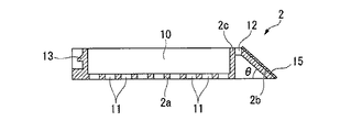
カセット本体2は、図4及び図5に示すように、上面視矩形状に形成されており、上面部分が収容凹部10の開口となっている。また、底面2aには、複数の貫通孔11がアレイ状に形成されており、該貫通孔11を介して収容凹部10の内部と外部とが連通するようになっている。また、本実施形態のカセット本体2の一端側には、表面が平らに形成された平坦面2bが形成されている。なお、この平坦面2bは、カセット本体2の底面2aに対して所定の角度θが付いた斜面となっている。
As shown in FIGS. 4 and 5, the
また、収容凹部10を囲む側壁部2cのうち、平坦面2bに隣接する部分には後述する蓋部3の係合片21が挿入される挿入孔12が形成されている。また、側壁部2cのうち、収容凹部10を間に挟んで挿入孔12に対向する側には、後述する蓋部3の係合爪22が係合する突起部13が形成されている。
Further, an
また、上述した平坦面2b上には、薄膜層15が設けられている。本実施形態の薄膜層15は、カセット本体2及び蓋部3と同様に、耐キシレン性及び耐アルコール性を有するフッ素樹脂やポリアセタール樹脂等の樹脂が成膜されたものである。この際、薄膜層15は、膜厚が5μm以上、500μm以下の範囲内に収まるように膜厚調整されている。また、この薄膜層15は、図示しないレーザマーカ装置等から照射されたレーザ光Lに沿って削られることで、識別コードCを表示するようになっている。これについては、後に詳細に説明する。
A
また、薄膜層15は、カセット本体2の色に対して少なくとも明度が異なる色とされている。本実施形態では、薄膜層15の色の方が、カセット本体2の色よりも低い明度になっている。具体的には、薄膜層15が、JIS-Z8102で規定される明度(V)が6.0以下の色である深緑(V=3.0)であり、カセット本体2及び蓋部3が、JIS-Z8102で規定される明度(V)が6.5以上の色である緑(V=6.5)となっている。
In addition, the
上記蓋部3は、図6及び図7に示すように、上面視矩形状に形成された板状の部材であり、カセット本体2の収容凹部10の側壁部2cを完全に覆うサイズに形成されている。また、蓋部3の下面には、矩形状に囲まれた段部3aが形成されている。この段部3aは、カセット本体2の側壁部2cに当接しながら収容凹部10内に入り込むサイズに形成されたものである。これにより、蓋部3をカセット本体2に重ねたときに、段部3aが収容凹部10内に入り込むので、蓋部3が水平方向に位置ずれしないようになっている。
また、この段部3aに囲まれた領域内には、カセット本体2と同様に複数の貫通孔20がアレイ状に形成されている。これにより、蓋部3をカセット本体2に重ねたときに、蓋部3側の貫通孔20を介して収容凹部10の内部と外部とが連通するようになっている。
As shown in FIGS. 6 and 7, the
Further, in the region surrounded by the
また、蓋部3の下面には、上述したカセット本体2の挿入孔12内に挿入される係合片21と、カセット本体2の突起部13に係合する係合爪22とが形成されている。係合片21は、カセット本体2の底面2aと平坦面2bとのなす角度θと略同じ角度で一端側から突出するように形成されており、挿入孔12内に挿入された後、平坦面2bの裏面側に面接触して蓋部3を位置決めするようになっている。また、係合爪22は、蓋部3の下面に対して略直交する方向に突出するように形成され、先端が鉤状になって突起部13に引っ掛かって係合するようになっている。
このように蓋部3は、段部3a及び係合片21によってカセット本体2に対して所定の位置に重ね合わされると共に、係合爪22を突起部13に係合することによって、カセット本体2に対して装着されるようになっている。
Further, on the lower surface of the
As described above, the
次に、上述した包埋カセット1を利用して包埋ブロックBを作製する場合について、説明する。
始めに作業者は、ホルマリン固定された生体試料Sを準備すると共に、該生体試料Sを収容するための図2及び図3に示す包埋カセット1を準備する。次に、作業者は、生体試料Sに関する必要な情報、例えば、実験動物の種類、臓器の種類等を予め識別コードCとして包埋カセット1に表示する作業を行う。具体的には、図8に示すように、市販されているレーザマーカ装置等を利用して、レーザ光Lを薄膜層15に照射する。すると、薄膜層15は、このレーザ光Lに沿って削り取られる。これにより、図9に示すように、包埋カセット1に対して、必要な情報を識別コードC(ABC20060423−A1201)として刻印することができる。
Next, the case where the embedding block B is produced using the embedding
First, the operator prepares the formalin-fixed biological sample S and prepares the embedding
包埋カセット1に識別コードCを刻印した後、カセット本体2から蓋部3を取り外す。次いで、刻印した識別コードCに該当する生体試料Sを適当な大きさに切断した後、カセット本体2の収容凹部10内に生体試料Sを収容する。そして収容した後、蓋部3をカセット本体2に装着して生体試料Sを内部に閉じ込める。つまり、蓋部3の係合片21をカセット本体2の挿入孔12に入れた状態で、蓋部3をカセット本体2に徐々に重ね合わせる。すると、係合片21側から徐々に蓋部3の段部3aがカセット本体2の収容凹部10内に入り込み始める。これにより、蓋部3が位置決めされるので、カセット本体2に対して蓋部3を正確に重ね合わせることができる。そして、最後に蓋部3の係合爪22をカセット本体2の突起部13に嵌め込むことで、蓋部3をカセット本体2に対して確実に装着することができ、収容凹部10の開口を閉塞することができる。
After the identification code C is engraved on the embedding
生体試料Sを閉じ込めた後、生体試料Sのパラフィン置換処理を行う。まず、図10に示すように、薬剤Wとしてアルコールw1が満たされたパレット30内に、包埋カセット1を浸漬する。この際、収容凹部10の内部は、カセット本体2及び蓋部3にそれぞれ形成されている貫通孔11、20を介して外部に連通しているので、アルコールw1が収容凹部10内に流入する。そのため、生体試料Sは、内部の水分や脂質がアルコールw1で置換、即ち、脱水処理、脱脂処理される。
After the biological sample S is confined, the biological sample S is subjected to paraffin substitution processing. First, as shown in FIG. 10, the embedding
次いで、パレット30内の薬剤Wをキシレンw2に入れ替える。これにより、先ほど置換したアルコールw1を、キシレンw2に置換する。そして、最後にパレット30内の薬剤Wを液状のパラフィンPに入れ換えて、先ほど置換したキシレンw2を、パラフィンPに置換する。これにより、水分や脂質がパラフィン置換処理された生体試料Sを作製することができる。
Next, the medicine W in the
このパラフィン置換処理作業が終了した後、図11に示すように、カセット本体2から蓋部3を取り外しておく。また、液状のパラフィンPが満たされた段部31aを有する包埋皿31を用意しておく。そして、カセット本体2の収容凹部10内から生体試料Sを取り出すと共に、取り出した生体試料Sを包埋皿31内に収容してパラフィンPに浸漬させる。また、これと同時に図12に示すように、空になったカセット本体2を包埋皿31の段部31aに載置して包埋皿31に蓋をする。この際、カセット本体2の収容凹部10内にもパラフィンPが入り込むように、パラフィンPの量が調整されている。この状態で、包埋皿31を冷却してパラフィンPを冷却固化させる。
After this paraffin replacement processing operation is completed, the
これにより、生体試料Sが包埋された包埋ブロックBを作製することができる。この際、包埋ブロックBは、カセット本体2の底面2aにくっ付いて繋がった状態となっている。そして、最後に図13に示すように、底面2aに包埋ブロックBが繋がったカセット本体2を包埋皿31から取り外して裏返しにする。その結果、カセット本体2の底面2a上に固体された包埋ブロックBを得ることができる。
Thereby, the embedding block B in which the biological sample S is embedded can be produced. At this time, the embedding block B is in a state of being attached to and connected to the
上述したように、包埋ブロックBを作製するにあたり、包埋カセット1を、生体試料Sのパラフィン置換処理を行うための容器として使用すると共に、包埋ブロックBの載置台として使用している。このように包埋カセット1を2つの場面で使用しているので、多数の生体試料Sを一度に処理したとしても、生体試料S同士の混同を防止することができる。しかも、カセット本体2には、図9に示すように、生体試料Sに関する識別コードCが表示されているので、品質管理を正確に行うことができる。
As described above, in producing the embedding block B, the embedding
特に、従来のような単に識別コードCを印字するだけの方法とは異なり、レーザ光Lを利用して薄膜層15を削り、識別コードCを刻印することができるので、包埋ブロックBを作製する作業中に識別コードCが擦れ等によって剥がれてしまうことがない。そのため、包埋ブロックBの品質管理を常に正確に行うことができる。
また、レーザ光Lを利用して識別コードCを刻印できるので、短時間の作業で済む。そのため、作業効率を向上することができる。また、非接触で識別コードCを刻印できるので、薄膜層15の表面粗さに影響を受けることなく識別コードCを表示することができる。またこれに加えて、印字される面とレーザマーカ装置の印字ヘッド面とが厳密に一致していなくても印字不良が生じない。そのため、過度の注意を払わずに薄膜層15を平坦面2b上に成膜することができる。
In particular, unlike the conventional method of simply printing the identification code C, the
Further, since the identification code C can be engraved using the laser beam L, a short time is required. Therefore, work efficiency can be improved. Further, since the identification code C can be engraved in a non-contact manner, the identification code C can be displayed without being affected by the surface roughness of the
また、薄膜層15の色は、カセット本体2の色に対して少なくとも明度が異なるので、薄膜層15を削って刻印した識別コードCを、背景色でもある薄膜層15の色とは異なる明度で表示することができる。そのため、識別コードCと背景色との明るさを変えることができ、明度差を利用して識別コードCを表示することができる。従って、コントラストを付けることができ、明瞭な視認性を確保することができる。
特に、本実施形態の場合には、薄膜層15の色が深緑であり、カセット本体2の色が緑である。つまり、薄膜層15の色の方が、カセット本体2の色よりも黒に近い暗色となっている。そのため、暗色とされた背景色の中に、該背景色よりも明るい色で識別コードCを表示することができる。よって、背景色と識別コードCとの明度差を明確につけることができ、視認性をより向上することができる。しかも、深緑は明度(V)が3.0であり、緑は明度(V)が6.5であるので、明度対比の効果によりコントラストがよりはっきりしている。よって、識別コードCをより鮮明に表示することができ見易い。
Further, since the color of the
In particular, in the present embodiment, the color of the
また、包埋ブロックBを作製した途中でパラフィンPが薄膜層15上に多少残っていたとしても、上述したように識別コードCの色と背景色の色との明度差を利用して高い視認性が確保されているので、従来のものに比較して識別コードCを鮮明に見ることができる。そのため、パラフィンPを手作業で削り落とす作業を省くこともでき、作業性を向上することができる。また仮にパラフィンPを削り落としたとしても、刻印によって識別コードCが表示されているので、従来のように識別コードCが剥がれてしまうことがない。
更に、刻印により表示されている識別コードCに、仮に白色のパラフィンPが付着してしまったとしても、該識別コードCがより明るい淡色となるので、コントラストがさらにつき易い。そのため、視認性に何ら影響を与えることがない。
Further, even if the paraffin P is left on the
Furthermore, even if white paraffin P is attached to the identification code C displayed by the engraving, the identification code C becomes a lighter and lighter color, so that the contrast is more easily given. Therefore, the visibility is not affected at all.
また、本実施形態の薄膜層15及びカセット本体2は、共に耐キシレン性、耐アルコール性を有する材料により形成されているので、パラフィン置換処理する際に使用したキシレンやアルコールの影響を何ら受けることがない。よって、耐久性を向上することができると共に、鮮明な識別コードCの表示を維持することができる。
In addition, since the
また、本実施形態の薄膜層15は、膜厚が5μm以上であるので、薄膜層として十分な強度を確保することができ、識別コードCをレーザ光Lで刻印する最中、或いは、識別コードCを刻印した後に、薄膜層15が剥がれてしまったり、欠けたりする恐れがない。よって、製品の信頼性を向上することができる。更に、薄膜層15は、膜厚が500μm以下であるので、市販されているレーザマーカ装置(例えば、炭酸ガスレーザマーカ装置)によるレーザ光Lで、容易且つ確実に薄膜層15を削って識別コードCを刻印することができる。また、仮に膜厚がこれより厚い場合には、幅が太くなり、刻印した際に字が潰れたり不鮮明になったりしてしまう。
In addition, since the
上述したように本実施形態の包埋カセット1によれば、レーザ光Lを利用して識別コードCを刻印することができ、剥がれ落ちを防止しながら、パラフィンPの影響を受けることなく識別コードCの表示を行うことができる。
As described above, according to the embedding
なお、本発明の技術範囲は上記実施の形態に限定されるものではなく、本発明の趣旨を逸脱しない範囲において種々の変更を加えることが可能である。 The technical scope of the present invention is not limited to the above embodiment, and various modifications can be made without departing from the spirit of the present invention.
例えば、上記実施形態において、薄膜層15を成膜した後に、表面をシボ加工や艶だし処理等によって鏡面処理しても構わない。こうすることで、薄膜層15の表面にパラフィンPが付着し難くなると共に、仮にパラフィンPが付着したとしても容易にパラフィンPを剥すことができる。
また、上記実施形態では、平坦面2b上に薄膜層15を成膜した場合を例に挙げて説明したが、成膜に限定されるものではない。例えば、平坦面2b上に、色素を含む熱硬化性樹脂を塗布することで薄膜層15を設けても構わない。こうすることで、より安価で効率良く包埋カセット1を製造することができる。特に、一液型エポキシ樹脂接着剤に無機系顔料を添加して色をつけた熱硬化性樹脂を用いることが好ましい。この熱硬化性樹脂を用いることで、確実にキシレンに耐えることができる。
For example, in the above-described embodiment, after the
In the above embodiment, the case where the
また、上記実施形態では、薄膜層15を深緑とし、カセット本体2を緑としたが、この色の組み合わせに限定されるものではない。少なくとも明度が異なる色であれば、自由に選択して構わない。但し、好ましくは、JIS−Z8102で規定される明度(V)が6.0以下の色を薄膜層15に選択し、明度(V)が6.5以上の色をカセット本体2の色に選択すると良い。その中でも、より好ましくは、薄膜層15の色を明度(V)が1.5の黒とし、カセット本体2の色を明度(V)が9.5の白とすることが好ましい。
In the above embodiment, the
また、上記実施形態では、平坦面2bが斜面となっていたが、この場合に限られず、カセット本体2の表面上に形成されていれば斜面でなくても構わないし、どの位置であっても構わない。
Moreover, in the said embodiment, although the
更に、上記実施形態では、カセット本体2上に薄膜層15を設け、該薄膜層15をレーザ光Lで削ることで識別コードCを表示する構成としたが、薄膜層15をなくし、カセット本体2及び蓋部3だけで包埋カセット1を構成しても構わない。
即ち、この場合には、カセット本体2を明度の異なるポリアセタール樹脂を2色成形して作製すれば良い。具体的には、それぞれ明度の異なる2色のポリアセタール樹脂を2層に積層してカセット本体2を成形する。しかもこれらポリアセタール樹脂は、レーザ光Lの照射によって削られるものである。そのため作業者は、包埋ブロックBを作製する際に、予め1層目のポリアセタール樹脂にレーザ光Lを照射して、識別コードCを刻印することができる。
Furthermore, in the above embodiment, the
That is, in this case, the
この際、積層されたポリアセタール樹脂の色は、それぞれ明度が異なる色となっている。そのため、1層目のポリアセタール樹脂を削って刻印した識別コードC(2層目のポリアセタール樹脂の色となっている)を、背景色でもある1層目のポリアセタール樹脂とは異なる明度で表示することができる。よって、薄膜層15の場合と同様に、明度差を利用して識別コードCを表示することができ、明瞭な視認性を確保することができる。
At this time, the colors of the laminated polyacetal resins are different in brightness. Therefore, the identification code C (which is the color of the second layer polyacetal resin) that is cut and engraved on the first layer polyacetal resin is displayed with a lightness different from that of the first layer polyacetal resin that is also the background color. Can do. Therefore, as in the case of the
B 包埋ブロック
C 識別コード
L レーザ光
P パラフィン(包埋剤)
S 生体試料
1 包埋カセット
2 カセット本体
2a カセット本体の底面
2b カセット本体の平坦面
3 蓋部
10 収容凹部
15 薄膜層
B Embedding block C Identification code L Laser beam P Paraffin (embedding agent)
S
Claims (8)
前記生体試料を収容する収容凹部が開口して形成され、表面上に平坦面が形成されたカセット本体と、
該カセット本体に対して着脱自在に固定され、前記収容凹部を閉塞する蓋部と、
前記カセット本体の色に対して少なくとも明度が異なる色で前記平坦面上に設けられた薄膜層とを備え、
該薄膜層は、照射されたレーザ光に沿って削られることで識別コードを表示することを特徴とする包埋カセット。 It is used as a container for performing paraffin substitution processing of a biological sample, and an embedding block in which the biological sample subjected to paraffin substitution processing is embedded in an embedding agent is placed, and a mounting table for the embedding block An embedding cassette used as
A cassette body in which an accommodation recess for accommodating the biological sample is formed to be open and a flat surface is formed on the surface;
A lid that is detachably fixed to the cassette body and closes the housing recess;
A thin film layer provided on the flat surface in a color different in brightness at least with respect to the color of the cassette body,
The embedding cassette, wherein the thin film layer is scraped along the irradiated laser beam to display an identification code.
前記薄膜層の色は、前記カセット本体の色よりも低い明度であることを特徴とする包埋カセット。 The embedding cassette according to claim 1,
The embedding cassette according to claim 1, wherein the color of the thin film layer is lighter than the color of the cassette body.
前記薄膜層は、JIS−Z8102で規定される明度(V)が6.0以下の色であり、
前記カセット本体は、JIS−Z8102で規定される明度(V)が6.5以上の色であることを特徴とする包埋カセット。 The embedding cassette according to claim 2,
The thin film layer has a lightness (V) defined by JIS-Z8102 of 6.0 or less,
The embedding cassette characterized in that the cassette body is a color having a lightness (V) defined by JIS-Z8102 of 6.5 or more.
前記カセット本体及び前記薄膜層は、耐キシレン性及び耐アルコール性を有する材料によりそれぞれ形成されていることを特徴とする包埋カセット。 In the embedding cassette according to any one of claims 1 to 3,
The embedding cassette according to claim 1, wherein the cassette body and the thin film layer are each formed of a material having xylene resistance and alcohol resistance.
前記薄膜層は、色素を含む熱硬化性樹脂が塗布されたものであることを特徴とする包埋カセット。 The embedding cassette according to any one of claims 1 to 4,
The embedding cassette, wherein the thin film layer is coated with a thermosetting resin containing a pigment.
前記薄膜層は、5μm以上、500μm以下の膜厚であることを特徴とする包埋カセット。 In the embedding cassette according to any one of claims 1 to 5,
The embedding cassette, wherein the thin film layer has a thickness of 5 μm or more and 500 μm or less.
前記薄膜層は、表面が鏡面処理されていることを特徴とする包埋カセット。 The embedding cassette according to any one of claims 1 to 6,
The embedding cassette, wherein the thin film layer has a mirror-finished surface.
前記生体試料を収容する収容凹部が開口して形成され、表面上に平坦面が形成されたカセット本体と、
該カセット本体に対して着脱自在に固定され、前記収容凹部を閉塞する蓋部とを備え、
前記カセット本体は、明度の異なるポリアセタール樹脂を2色成形して作製されたものであり、前記平坦面上に照射されたレーザ光に沿って削られることで識別コードを表示することを特徴とする包埋カセット。
The embedding block is used as a container for performing paraffin substitution processing on a biological sample, and an embedding block in which the biological sample subjected to paraffin substitution processing is embedded in an embedding agent is placed. An embedding cassette used as
A cassette body in which an accommodation recess for accommodating the biological sample is formed to be open and a flat surface is formed on the surface;
A lid that is detachably fixed to the cassette body and closes the housing recess,
The cassette body is produced by molding two colors of polyacetal resins having different brightness, and displays an identification code by being cut along the laser beam irradiated on the flat surface. Embedding cassette.
Priority Applications (3)
| Application Number | Priority Date | Filing Date | Title |
|---|---|---|---|
| JP2006198090A JP2008026112A (en) | 2006-07-20 | 2006-07-20 | Embedded cassette |
| US11/880,388 US20080044315A1 (en) | 2006-07-20 | 2007-07-19 | Embedding cassette |
| EP07252880A EP1884285A1 (en) | 2006-07-20 | 2007-07-20 | Embedding cassette with laser marking |
Applications Claiming Priority (1)
| Application Number | Priority Date | Filing Date | Title |
|---|---|---|---|
| JP2006198090A JP2008026112A (en) | 2006-07-20 | 2006-07-20 | Embedded cassette |
Publications (2)
| Publication Number | Publication Date |
|---|---|
| JP2008026112A true JP2008026112A (en) | 2008-02-07 |
| JP2008026112A5 JP2008026112A5 (en) | 2009-05-28 |
Family
ID=38805729
Family Applications (1)
| Application Number | Title | Priority Date | Filing Date |
|---|---|---|---|
| JP2006198090A Withdrawn JP2008026112A (en) | 2006-07-20 | 2006-07-20 | Embedded cassette |
Country Status (3)
| Country | Link |
|---|---|
| US (1) | US20080044315A1 (en) |
| EP (1) | EP1884285A1 (en) |
| JP (1) | JP2008026112A (en) |
Cited By (7)
| Publication number | Priority date | Publication date | Assignee | Title |
|---|---|---|---|---|
| WO2010023898A1 (en) * | 2008-08-29 | 2010-03-04 | セイコーインスツル株式会社 | Embedding cassette |
| WO2011149100A1 (en) * | 2010-05-24 | 2011-12-01 | 竹崎 岳志 | Unit system for treatment of pathological/biopsy sample |
| JP2011247640A (en) * | 2010-05-24 | 2011-12-08 | Tanizaki Teiji | Unit construct device for forming embedding block for biological sample, including independent basket for biological sample processing that can perform fixation, transfer and liquid chemical processing of biological sample and be unit-connected and fitted with embedding frame-like base body, unit connected and fitted construct cassette for biological sample and burr-free embedding tray which is the unit construct device |
| JP2011247647A (en) * | 2010-05-24 | 2011-12-08 | Tanizaki Teiji | Mount for sample fixation and transfer and sample embedding fixation supporting agent using two kinds of polymers of different shapes/functions and using method thereof |
| JP2014523343A (en) * | 2011-05-26 | 2014-09-11 | マリオ・チンティ | Tissue embedding cassette marking device |
| JP2018069295A (en) * | 2016-10-31 | 2018-05-10 | 有限会社品川通信計装サービス | Marking apparatus for marking on marking slide glass and marking embedding cassette, and marking method using this apparatus |
| JP2022053641A (en) * | 2020-09-25 | 2022-04-06 | 株式会社ライズ・アップ | Automatic vending machine equipped with manual operation type commodity conveyance mechanism |
Families Citing this family (2)
| Publication number | Priority date | Publication date | Assignee | Title |
|---|---|---|---|---|
| JP2010054480A (en) * | 2008-08-29 | 2010-03-11 | Seiko Instruments Inc | Embedding cassette printing apparatus |
| KR102846474B1 (en) * | 2023-12-27 | 2025-08-14 | 충남대학교병원 | Tissue Cassette For Digital Slide Scanner |
Citations (10)
| Publication number | Priority date | Publication date | Assignee | Title |
|---|---|---|---|---|
| JPH01238983A (en) * | 1988-03-18 | 1989-09-25 | Fujitsu Ltd | Bar code marking method |
| JPH0473843A (en) * | 1990-07-12 | 1992-03-09 | Matsushita Electric Ind Co Ltd | deflection yoke |
| JPH07266695A (en) * | 1994-03-30 | 1995-10-17 | Rohm Co Ltd | Electronic part and method for marking the same |
| JPH08285856A (en) * | 1995-04-13 | 1996-11-01 | Daiichi Kigyo:Kk | Prepared specimen with retrieving means |
| JPH11132923A (en) * | 1997-10-27 | 1999-05-21 | Chiyoda Mfg Co Ltd | Sliding glass with information recording device and embedding cassette |
| JP2001324428A (en) * | 2000-05-15 | 2001-11-22 | Murazumi Kogyo Kk | Cassette for medical test |
| JP2002005800A (en) * | 2000-06-23 | 2002-01-09 | Murazumi Kogyo Kk | Cassette for medical examination |
| JP2002082120A (en) * | 2000-09-06 | 2002-03-22 | Itochu Fine Chemical Corp | Automatic information-readable container for living organism/biological and automatic information reading system |
| US6518542B1 (en) * | 2001-10-11 | 2003-02-11 | Infosight Corporation | Colored patch laser marking |
| JP2005103423A (en) * | 2003-09-30 | 2005-04-21 | Fuji Kagaku Kk | Microchemistry device |
Family Cites Families (9)
| Publication number | Priority date | Publication date | Assignee | Title |
|---|---|---|---|---|
| JPH0540449Y2 (en) * | 1987-10-14 | 1993-10-14 | ||
| JP3104307B2 (en) * | 1991-06-28 | 2000-10-30 | ソニー株式会社 | Plate material for gravure printing |
| US5428857A (en) * | 1992-07-20 | 1995-07-04 | Milliken Research Corporation | Identifiable rubber backed product |
| US5532168A (en) * | 1994-08-18 | 1996-07-02 | Marantz; Calvin | Tissue biopsy specimen strainer and method |
| US6007929A (en) * | 1997-02-20 | 1999-12-28 | Infosight Corporation | Dual paint coat laser-marking labeling system, method and product |
| DE10154843A1 (en) * | 2001-11-08 | 2003-05-28 | Microm Int Gmbh | Method and device for labeling slides for microtomized tissue samples and their processing |
| DE10342264C5 (en) * | 2003-09-12 | 2012-10-31 | Leica Biosystems Nussloch Gmbh | System for uniquely assigning histological cassettes and slides |
| US7123280B2 (en) * | 2003-09-29 | 2006-10-17 | Konica Minolta Photo Imaging, Inc. | Thermal transfer image receiving sheet and image forming method using the same |
| DE202004018921U1 (en) * | 2004-12-06 | 2005-02-17 | Eppendorf Ag | microtiter plate |
-
2006
- 2006-07-20 JP JP2006198090A patent/JP2008026112A/en not_active Withdrawn
-
2007
- 2007-07-19 US US11/880,388 patent/US20080044315A1/en not_active Abandoned
- 2007-07-20 EP EP07252880A patent/EP1884285A1/en not_active Withdrawn
Patent Citations (10)
| Publication number | Priority date | Publication date | Assignee | Title |
|---|---|---|---|---|
| JPH01238983A (en) * | 1988-03-18 | 1989-09-25 | Fujitsu Ltd | Bar code marking method |
| JPH0473843A (en) * | 1990-07-12 | 1992-03-09 | Matsushita Electric Ind Co Ltd | deflection yoke |
| JPH07266695A (en) * | 1994-03-30 | 1995-10-17 | Rohm Co Ltd | Electronic part and method for marking the same |
| JPH08285856A (en) * | 1995-04-13 | 1996-11-01 | Daiichi Kigyo:Kk | Prepared specimen with retrieving means |
| JPH11132923A (en) * | 1997-10-27 | 1999-05-21 | Chiyoda Mfg Co Ltd | Sliding glass with information recording device and embedding cassette |
| JP2001324428A (en) * | 2000-05-15 | 2001-11-22 | Murazumi Kogyo Kk | Cassette for medical test |
| JP2002005800A (en) * | 2000-06-23 | 2002-01-09 | Murazumi Kogyo Kk | Cassette for medical examination |
| JP2002082120A (en) * | 2000-09-06 | 2002-03-22 | Itochu Fine Chemical Corp | Automatic information-readable container for living organism/biological and automatic information reading system |
| US6518542B1 (en) * | 2001-10-11 | 2003-02-11 | Infosight Corporation | Colored patch laser marking |
| JP2005103423A (en) * | 2003-09-30 | 2005-04-21 | Fuji Kagaku Kk | Microchemistry device |
Cited By (8)
| Publication number | Priority date | Publication date | Assignee | Title |
|---|---|---|---|---|
| WO2010023898A1 (en) * | 2008-08-29 | 2010-03-04 | セイコーインスツル株式会社 | Embedding cassette |
| CN102138065A (en) * | 2008-08-29 | 2011-07-27 | 精工电子有限公司 | Embedding cassette |
| WO2011149100A1 (en) * | 2010-05-24 | 2011-12-01 | 竹崎 岳志 | Unit system for treatment of pathological/biopsy sample |
| JP2011247640A (en) * | 2010-05-24 | 2011-12-08 | Tanizaki Teiji | Unit construct device for forming embedding block for biological sample, including independent basket for biological sample processing that can perform fixation, transfer and liquid chemical processing of biological sample and be unit-connected and fitted with embedding frame-like base body, unit connected and fitted construct cassette for biological sample and burr-free embedding tray which is the unit construct device |
| JP2011247647A (en) * | 2010-05-24 | 2011-12-08 | Tanizaki Teiji | Mount for sample fixation and transfer and sample embedding fixation supporting agent using two kinds of polymers of different shapes/functions and using method thereof |
| JP2014523343A (en) * | 2011-05-26 | 2014-09-11 | マリオ・チンティ | Tissue embedding cassette marking device |
| JP2018069295A (en) * | 2016-10-31 | 2018-05-10 | 有限会社品川通信計装サービス | Marking apparatus for marking on marking slide glass and marking embedding cassette, and marking method using this apparatus |
| JP2022053641A (en) * | 2020-09-25 | 2022-04-06 | 株式会社ライズ・アップ | Automatic vending machine equipped with manual operation type commodity conveyance mechanism |
Also Published As
| Publication number | Publication date |
|---|---|
| EP1884285A1 (en) | 2008-02-06 |
| US20080044315A1 (en) | 2008-02-21 |
Similar Documents
| Publication | Publication Date | Title |
|---|---|---|
| EP1884285A1 (en) | Embedding cassette with laser marking | |
| AU578714B2 (en) | Method and apparatus for identification of histology samples | |
| US20060008790A1 (en) | Methods and apparatuses for the automated production, collection, handling, and imaging of large numbers of serial tissue sections | |
| WO2010023898A1 (en) | Embedding cassette | |
| JP2019511736A (en) | Method and apparatus for imaging an uncut tissue specimen | |
| US20100073766A1 (en) | Microscope slide testing and identification assembly | |
| US9594087B2 (en) | Cassette | |
| US20140022631A1 (en) | Microscope slide for specimen tracking and verification, and method of making same | |
| JP2002125656A (en) | Cell culture vessel | |
| US20080044649A1 (en) | Identification code labeling tape | |
| JP2002303568A (en) | Cassette for pathological tissue sample and method for forming embedded block using the same | |
| US20260008058A1 (en) | Methods for processing a pathology specimen | |
| US20060239867A1 (en) | Radio frequency identification (RFID) in laboratories | |
| US20100072272A1 (en) | Microscope slide coverslip and uses thereof | |
| JP2002005800A (en) | Cassette for medical examination | |
| US20240077712A1 (en) | Microscope Slide and Method for Selecting the Same | |
| JP2025505368A (en) | Method for marking a plastic object for laboratory use and a plastic object for laboratory use comprising a mark - Patents.com | |
| JP2008026112A5 (en) | ||
| JP2020079759A (en) | Tray for storing cassette for medical examination and method of printing examination information on cassette for medical examination using the same | |
| JP6473314B2 (en) | Paraffin block making tool | |
| JP2002214093A (en) | Medical examination cassette | |
| JP2016099547A (en) | Display member, culture container, and culture container kit | |
| JP4642498B2 (en) | Cassette for medical examination and method of manufacturing cassette block using the cassette | |
| US20240246079A1 (en) | Cassette Assembly | |
| IT201800008000A1 (en) | Laser printer for histological and cytological slides. |
Legal Events
| Date | Code | Title | Description |
|---|---|---|---|
| A521 | Written amendment |
Free format text: JAPANESE INTERMEDIATE CODE: A523 Effective date: 20090409 |
|
| A621 | Written request for application examination |
Free format text: JAPANESE INTERMEDIATE CODE: A621 Effective date: 20090409 |
|
| A977 | Report on retrieval |
Free format text: JAPANESE INTERMEDIATE CODE: A971007 Effective date: 20110525 |
|
| A131 | Notification of reasons for refusal |
Free format text: JAPANESE INTERMEDIATE CODE: A131 Effective date: 20110531 |
|
| A761 | Written withdrawal of application |
Free format text: JAPANESE INTERMEDIATE CODE: A761 Effective date: 20110705 |