JP2008015283A - Image forming apparatus - Google Patents
Image forming apparatus Download PDFInfo
- Publication number
- JP2008015283A JP2008015283A JP2006187235A JP2006187235A JP2008015283A JP 2008015283 A JP2008015283 A JP 2008015283A JP 2006187235 A JP2006187235 A JP 2006187235A JP 2006187235 A JP2006187235 A JP 2006187235A JP 2008015283 A JP2008015283 A JP 2008015283A
- Authority
- JP
- Japan
- Prior art keywords
- transfer material
- image forming
- forming apparatus
- toner
- cleaning
- Prior art date
- Legal status (The legal status is an assumption and is not a legal conclusion. Google has not performed a legal analysis and makes no representation as to the accuracy of the status listed.)
- Pending
Links
Images


Landscapes
- Fixing For Electrophotography (AREA)
- Control Or Security For Electrophotography (AREA)
Abstract
Description
本発明は、プリンタ、複写機、ファクシミリ等の画像形成装置に関するものである。特に、互いに圧接してニップ領域を形成して回転する定着回転体及び加圧回転体を備え定着装置において少なくとも一方の回転体に付着したトナーをクリーニングするクリーニング手段を有した画像形成装置に関するものである。 The present invention relates to an image forming apparatus such as a printer, a copying machine, and a facsimile. More particularly, the present invention relates to an image forming apparatus having a fixing rotator that rotates in contact with each other to form a nip region and a pressure rotator, and having cleaning means for cleaning toner adhering to at least one of the rotators in the fixing device. is there.
従来、画像形成装置における定着装置のクリーニングに関するものとして、特許文献1に開示されているように、給紙カセットにセットされている転写材などをクリーニングペーパとして使用し、定期的にクリーニングペーパを定着ニップ部に自動的に通過させ、クリーニングローラに付着したトナーを回収しているものがある。
しかしながら、上記の方法では、定着装置のクリーニングの際には、給紙カセットにセットされている未使用の転写材などとされるメディアをクリーニングペーパとして使用しており、定着装置をクリーニングするということだけに主眼が置かれている。 However, in the above method, when the fixing device is cleaned, a medium such as an unused transfer material set in a paper feeding cassette is used as cleaning paper, and the fixing device is cleaned. The main focus is only on.
そこで、本発明者は、従来のカラー画像形成装置などにおいて定期的に行われている、濃度又は色度検知手段(カラーセンサ)による色補正時に使用される校正シートや、画像形成装置内に詰まったジャム(JAM)紙をクリーニングペーパとして使用することに着目し、上述した方法が有する問題を解消し得ることが分かった。本発明は、斯かる本発明者の新規な知見に基づくものである。 Therefore, the present inventor has jammed in a calibration sheet used for color correction by a density or chromaticity detection means (color sensor) regularly performed in a conventional color image forming apparatus or the like, or in the image forming apparatus. Focusing on the use of JAM paper as cleaning paper, it has been found that the above-described problems can be solved. The present invention is based on the novel knowledge of the present inventors.
本発明の目的は、不必要となる転写材の枚数を減らすことができ、そして、時間削減、さらには、ユーザビリティの向上を図ることのできる画像形成装置を提供することである。 An object of the present invention is to provide an image forming apparatus capable of reducing the number of unnecessary transfer materials, reducing time, and improving usability.
上記目的は本発明に係る画像形成装置にて達成される。要約すれば、本発明の第一の態様によれば、
トナー像を転写材に形成する画像形成部と、
トナー像が形成された転写材を挟持して、加熱及び加圧によりトナー像を転写材上に定着する一対の回転体と、少なくとも一方の前記回転体に付着したトナーをクリーニングするクリーニング手段と、を備えた定着装置と、
を備えた画像形成装置において、
前記画像形成部にて形成された濃度又は色度制御用カラートナーパッチを、前記定着装置にて前記転写材上に定着し、
前記転写材上に定着されたパッチの濃度又は色度を濃度又は色度検知手段にて検知し、
前記検知されたパッチの濃度又は色度に基づいて画像形成条件を制御する制御手段を備え、
前記制御手段による濃度又は色度制御を行う場合には、
(i)前記濃度又は色度制御用カラートナーパッチを前記転写材上に定着した後、前記回転体を所定温度に加熱して空回転させ、前記クリーニング手段に付着したトナーを前記両回転体に逆流させ、
(ii)更に、前記濃度又は色度制御用カラートナーパッチが定着された前記転写材を前記定着装置へと送給し、前記両回転体にて挟持して加熱及び加圧し、前記両回転体上のトナーを前記転写材にて回収する、
前記クリーニング手段をクリーニングするためのクリーニングモードを備えている、
ことを特徴とする画像形成装置が提供される。
The above object is achieved by the image forming apparatus according to the present invention. In summary, according to the first aspect of the present invention,
An image forming unit for forming a toner image on a transfer material;
A pair of rotating bodies that sandwich the transfer material on which the toner image is formed and fix the toner image on the transfer material by heating and pressurizing; and a cleaning unit that cleans the toner adhering to at least one of the rotating bodies; A fixing device comprising:
In an image forming apparatus comprising:
The density or chromaticity control color toner patch formed by the image forming unit is fixed on the transfer material by the fixing device,
The density or chromaticity of the patch fixed on the transfer material is detected by the density or chromaticity detection means,
Control means for controlling image forming conditions based on the detected density or chromaticity of the patch;
When performing density or chromaticity control by the control means,
(I) After fixing the density or chromaticity control color toner patch on the transfer material, the rotating body is heated to a predetermined temperature and rotated idly, and the toner adhering to the cleaning means is applied to the rotating bodies. Backflow,
(Ii) Further, the transfer material on which the density or chromaticity control color toner patch is fixed is fed to the fixing device, and is sandwiched and heated and pressurized by the rotary members. Collect the toner on the transfer material,
A cleaning mode for cleaning the cleaning means;
An image forming apparatus is provided.
本発明の第二の態様によれば、
トナー像を転写材に形成する画像形成部と、
トナー像が形成された転写材を挟持して、加熱及び加圧によりトナー像を転写材上に定着する一対の回転体と、少なくとも一方の前記回転体に付着したトナーをクリーニングするクリーニング手段と、を備えた定着装置と、
前記転写材のジャムを検知する検知手段と、
を備えた画像形成装置において、
前記検知手段が画像形成装置内での転写材のジャムを検知し、画像形成装置内に前記定着装置にてトナー像が定着された転写材が残留している場合には、
(i)前記回転体を所定温度に加熱して空回転させ、前記クリーニング手段に付着したトナーを前記両回転体に逆流させ、
(ii)更に、前記画像形成装置内に残留する、トナー像が定着された転写材を前記定着装置へと送給し、前記転写材を前記両回転体にて挟持して加熱及び加圧し、前記両回転体上のトナーを前記転写材にて回収する、
前記クリーニング手段をクリーニングするためのクリーニングモードを備えている、
ことを特徴とする画像形成装置が提供される。
According to a second aspect of the invention,
An image forming unit for forming a toner image on a transfer material;
A pair of rotating bodies that sandwich the transfer material on which the toner image is formed and fix the toner image on the transfer material by heating and pressurizing; and a cleaning unit that cleans the toner adhering to at least one of the rotating bodies; A fixing device comprising:
Detecting means for detecting the jam of the transfer material;
In an image forming apparatus comprising:
When the detection unit detects a jam of the transfer material in the image forming apparatus, and the transfer material on which the toner image is fixed by the fixing device remains in the image forming apparatus,
(I) heating the rotating body to a predetermined temperature and causing it to idle, causing the toner adhering to the cleaning means to flow back to both rotating bodies;
(Ii) Further, the transfer material remaining in the image forming apparatus and having the toner image fixed thereon is fed to the fixing device, and the transfer material is sandwiched between the rotating members and heated and pressurized, Collecting the toner on both of the rotating bodies with the transfer material;
A cleaning mode for cleaning the cleaning means;
An image forming apparatus is provided.
本発明によれば、定期的に行われているカラーセンサによる色補正時に使用される校正シートや画像形成装置内に詰まったジャム(JAM)紙をクリーニングペーパとして使用することにより、不必要となる転写材の枚数を減らすことができ、更には、改めてクリーニングモードを行なう必要がないことによる時間削減、そして、ユーザにクリーニングモードを実行させる手間の削減につながり、ユーザビリティの向上を図ることができる。 According to the present invention, it is unnecessary to use a calibration sheet used during color correction by a color sensor performed regularly or jammed (JAM) paper jammed in the image forming apparatus as cleaning paper. The number of transfer materials can be reduced, and further, the time can be reduced by not having to perform the cleaning mode again, and the time and effort for the user to execute the cleaning mode can be reduced, thereby improving the usability.
以下、本発明に係る画像形成装置を図面に則して更に詳しく説明する。 The image forming apparatus according to the present invention will be described below in more detail with reference to the drawings.
実施例1
図1に、本発明に係る画像形成装置の一実施例の概略構成を示す。本実施例にて、画像形成装置は、カラー画像形成装置の一例であるカラーレーザプリンタとされる。先ず、画像形成装置の全体構成について説明する。
Example 1
FIG. 1 shows a schematic configuration of an embodiment of an image forming apparatus according to the present invention. In this embodiment, the image forming apparatus is a color laser printer which is an example of a color image forming apparatus. First, the overall configuration of the image forming apparatus will be described.
(画像形成装置の全体構成)
本実施例によると、斜め方向に4つの画像形成部、即ち、イエロー(Y)、マゼンタ(M)、シアン(C)、及び、ブラック(Bk)の画像形成部P(Pa、Pb、Pc、Pd)が並設されている。各画像形成部P(Pa、Pb、Pc、Pd)はそれぞれ、ドラム状の電子写真感光体(以下、「感光体ドラム」という。)1(1a、1b、1c、1d)を備えている。
(Overall configuration of image forming apparatus)
According to the present embodiment, four image forming portions in an oblique direction, that is, yellow (Y), magenta (M), cyan (C), and black (Bk) image forming portions P (Pa, Pb, Pc, Pd) are juxtaposed. Each image forming unit P (Pa, Pb, Pc, Pd) includes a drum-shaped electrophotographic photosensitive member (hereinafter referred to as “photosensitive drum”) 1 (1a, 1b, 1c, 1d).
各感光体ドラム1の周囲には、感光体ドラム1の表面を均一に帯電するための一次帯電手段となる一次帯電器(本実施例では帯電ローラ)2(2a、2b、2c、2d)が配置されている。また、画像形成装置は、一次帯電器2により一様に帯電された感光体ドラム1の表面に、画像情報に基づいてレーザビームを照射して静電潜像を形成する露光手段としてのレーザービームスキャナ3(3a、3b)が配置されている。 Around each photosensitive drum 1, there is a primary charger (charging roller in this embodiment) 2 (2a, 2b, 2c, 2d) as primary charging means for uniformly charging the surface of the photosensitive drum 1. Has been placed. In addition, the image forming apparatus irradiates the surface of the photosensitive drum 1 uniformly charged by the primary charger 2 with a laser beam based on image information to form an electrostatic latent image as a laser beam as an exposure unit. A scanner 3 (3a, 3b) is arranged.
そして、各感光体ドラム1の周りには、現像手段としての現像装置40(40a、40b、40c、40d)が配置されており、静電潜像が形成された感光体ドラム1の表面にイエロー(Y)、マゼンタ(M)、シアン(C)、及び、ブラック(Bk)の各色のトナーを付着させて、トナー画像として顕像化する。 A developing device 40 (40a, 40b, 40c, 40d) as a developing unit is disposed around each photosensitive drum 1, and yellow is formed on the surface of the photosensitive drum 1 on which the electrostatic latent image is formed. (Y), magenta (M), cyan (C), and black (Bk) toners are attached to be visualized as a toner image.
また、現像装置40は、プロセスカートリッジ7(7a、7b、7c、7d)と、トナーカートリッジ5(5a、5b、5c、5d)とにユニット化されている。 The developing device 40 is unitized into a process cartridge 7 (7a, 7b, 7c, 7d) and a toner cartridge 5 (5a, 5b, 5c, 5d).
感光体ドラム1(1a、1b、1c、1d)に対向して、感光体ドラム1(1a、1b、1c、1d)の表面に形成されたトナー画像が一次転写される中間転写体となる中間転写ベルト10が配置される。中間転写ベルト10は、駆動ローラ10a、従動ローラ10b、アイドラローラ10cにより張架されており、中間転写ベルト10を挟んで従動ローラ10bに対向する位置に2次転写手段としての二次転写ローラ16が配置されている。中間転写ベルト10、二次転写ローラ16などにより中間転写ユニット15を構成する。
Opposite to the photosensitive drum 1 (1a, 1b, 1c, 1d), an intermediate transfer member is an intermediate transfer member on which the toner image formed on the surface of the photosensitive drum 1 (1a, 1b, 1c, 1d) is primarily transferred. A
各感光体ドラム1上に形成されたトナー画像は、一次転写手段としての一次転写ローラ12(12a、12b、12c、12d)の作用により中間転写ベルト10に一次転写される。
The toner image formed on each photosensitive drum 1 is primarily transferred to the
転写後の感光体ドラム1の表面に残留したトナーは、クリーニング手段8(8a、8b、8c、8d)にて除去される。 The toner remaining on the surface of the photosensitive drum 1 after the transfer is removed by the cleaning means 8 (8a, 8b, 8c, 8d).
一方、給紙カセット11からピックアップローラ9により繰り出された転写材11aは、フィードローラ51aとリタードローラ52aの分離手段により1枚ずつ分離給送された後、搬送ローラ対13aによりレジストローラ対17に送られる。また、マルチトレイ50から給紙される場合には、フィードローラ51bとリタードローラ52bの分離手段により1枚ずつ分離給送された後、搬送ローラ対13bによりレジストローラ対17に送られる。転写材11aは、レジストローラ対17により、所定のタイミングで中間転写ベルト10と二次転写ローラ16との間に搬送され、該二次転写ローラ16の作用により中間転写ベルト10に一次転写されたトナー画像が二次転写される。
On the other hand, the
トナー画像が転写された転写材11aは、定着手段としての定着装置14によりトナー画像が定着された後、不図示のソレノイド等の手段により切り換えられる切換レバー55が、図1に示す位置55aの位置にあるときには排出ローラ対20により搬送されて、装置本体の上部に設けられた排出トレイ21上に排出される。また、切換レバー55が、図2に示すように、位置55bの位置にあるときには、搬送ローラ対13cにより両面搬送パス30部のスイッチバックローラ対31へと搬送され、スイッチバックローラ対31により搬送方向が切り換えられ、搬送ローラ対13d、13e、13fを通り、再度レジストローラ対17へと搬送される。
The
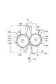
ここで、図3を用いて、一般的な画像形成装置に用いられる定着装置14について説明する。
Here, the fixing
図3に示すように、本実施例にて、定着装置14は、定着回転体としての定着ローラ140と、加圧回転体としての加圧ローラ160とを備えている。定着ローラ140は、一例としてアルミニウムや鉄等の金属芯金141上にPFA、PTFE等の離型性樹脂層142を設け、また、内部はヒータ143によって加熱されるようになっている。定着ローラ140の温度は、定着ローラ140に当接する温度検知手段としての温度検出素子150によって定着ローラ140の表面温度を検知され、温度制御回路がヒータ143を断続的に作動させることにより、定着ローラ140の表面温度は所定の温度に制御される。
As shown in FIG. 3, in this embodiment, the fixing
一方、定着ローラ140に圧接し回転する加圧ローラ160は、一例としてアルミニウムや鉄等の金属芯金161上に耐熱性を有しかつ硬度の低いシリコンゴムやシリコンスポンジ等の弾性層162を設け、その表面にPFA、PTFE等の離型性の高い樹脂による被膜層を有した構造とされる。また、内部はヒータ163によって加熱されるようになっている。加圧ローラ160の温度は、加圧ローラ160に当接する温度検知手段としての温度検出素子151によって加圧ローラ160の表面温度を検知され、温度制御回路がヒータ163を断続的に作動させることにより、加圧ローラ160の表面温度も定着ローラ140同様、所定の温度に制御される。
On the other hand, the
また、転写材に含まれる炭酸カルシウム粉の付着により、定着ローラ140の表面の離型性が低下することで、オフセットは悪化する。このオフセットトナーは、転写材の搬送間隔において、離型性の差により定着ローラ140の表面から加圧ローラ160の表面に転移して加圧ローラ160の表面に蓄積する。このような過程で加圧ローラ160に付着や蓄積したトナーは、転写材の裏面汚れや再び定着ローラ140に戻り、転写材の表面汚れを引き起こす。
Also, the offset deteriorates due to a decrease in the releasability of the surface of the fixing
さらに、紙サイズより大きめの画像を描き、余白無しの「縁無し」印刷時には、定着ローラ140や加圧ローラ160の表面にトナーが付き、転写材の表面や裏面の汚れを引き起こす。そのため、定着ローラ140及び加圧ローラ160の少なくとも一方に、本実施例では、定着ローラ140及び加圧ローラ160のそれぞれに、クリーニング手段としてのクリーニング回転体、即ち、クリーニングローラ145及び165を当接させることで、ローラの表面に付着したトナーを回収している。クリーニングローラ145、165は、温まりやすい方がトナーのクリーニング性が向上するために、通常、熱容量の小さいアルミニウムなどの金属にて作製される。
Furthermore, when an image larger than the paper size is drawn and “marginless” printing is performed without margins, toner is attached to the surfaces of the fixing
また、クリーニングローラ145は定着ローラ140に、クリーニングローラ165は加圧ローラ160に対してそれぞれ不図示のカム機構等により接離可能であり、当接時に従動して回転する構成となっている。
The cleaning
また、本画像形成装置は、特殊転写材モードを有しており、不図示のオペレータ操作パネルやホストコンピュータ等から特殊転写材設定を行なえるようになっており、ユーザがモードを選択することにより転写材の種類や厚さに応じて、転写材の搬送スピードや定着温度等のプロセス条件を一部変更できる。 In addition, the image forming apparatus has a special transfer material mode, and a special transfer material can be set from an operator operation panel (not shown), a host computer, or the like, and the user selects the mode. Depending on the type and thickness of the transfer material, part of the process conditions such as transfer material conveyance speed and fixing temperature can be changed.
さらに、本実施例のようなカラー画像形成装置において近年、出力画像の高画質化が求められている。特に、濃度の階調とその安定性は、人間が下す画像の良し悪しの判断に大きな影響を与える。 Further, in recent years, a color image forming apparatus such as the present embodiment has been required to improve the quality of output images. In particular, the gradation of the density and its stability have a great influence on the judgment of the quality of an image given by a human.
ところが、上記構成のカラー画像形成装置は、環境の変化や長時間の使用による装置各部の変動があると、得られる画像の濃度が変動してしまう。 However, in the color image forming apparatus having the above-described configuration, the density of an image to be obtained fluctuates when there are fluctuations in each part of the apparatus due to environmental changes or long-term use.
特に、電子写真方式のカラー画像形成装置の場合、わずかな濃度の変動でもカラーバランスが崩れてしまう。そのために、イエロー(Y)、マゼンタ(M)、シアン(C)、ブラック(Bk)の各色のトナーに対して、絶対湿度に応じた数種類の露光量や現像バイアスなどのプロセス条件、ルックアップテーブル(LUT)などの階調補正手段をもち、温湿度センサによって測定された絶対湿度に基づいて、その時のプロセス条件や階調補正の最適値を選択している。 In particular, in the case of an electrophotographic color image forming apparatus, even a slight change in density causes the color balance to be lost. Therefore, for yellow (Y), magenta (M), cyan (C), and black (Bk) toners, several kinds of process conditions such as exposure amount and development bias according to absolute humidity, look-up table, etc. It has tone correction means such as (LUT), and based on the absolute humidity measured by the temperature and humidity sensor, the process conditions at that time and the optimum value for tone correction are selected.
また、装置各部の変動が起こっても一定の濃度−階調特性が得られるように、各色のトナーで濃度検知用トナーパッチを中間転写ベルトや感光体ドラム等の上に作成し、その未定着トナーパッチの濃度を未定着トナー用濃度検知手段(濃度検知センサ)201(図1参照)で検知し、その検知結果より露光量、現像バイアスなどのプロセス条件にフィードバックをかけて濃度制御を行なうことで、安定した画像を得るように構成している。 In addition, a density detection toner patch is created on the intermediate transfer belt, the photosensitive drum, etc. with toner of each color so that a constant density-gradation characteristic can be obtained even if each part of the apparatus fluctuates. The density detection means (density detection sensor) 201 (see FIG. 1) for unfixed toner detects the density of the toner patch, and density control is performed by feeding back process conditions such as exposure amount and development bias based on the detection result. Thus, a stable image is obtained.
しかし、従来の画像形成装置においては、上記未定着トナー用濃度検知センサ201を用いた濃度制御は、パッチを中間転写ベルトや感光体ドラム等の上に形成し検知するもので、その後に行われる転写材11aへの転写及び定着による画像のカラーバランスの変化については制御していない。
However, in the conventional image forming apparatus, the density control using the unfixed toner
転写材11aへのトナー像の転写における転写効率や、定着による加熱及び加圧によってもカラーバランスが変化する。
The color balance also changes depending on the transfer efficiency in transferring the toner image to the
この変化には、上記未定着トナー用濃度検知センサ201を用いた濃度制御では対応できない。
This change cannot be handled by density control using the
(濃度又は色度制御モード)
そこで、本発明では、濃度又は色度制御モードを有している。濃度又は色度制御モードでは、転写、定着後に転写材11a上の単色トナー画像の濃度又はフルカラー画像の色度を検知する濃度又は色度検知手段(以下、「カラーセンサ」という。)200(図1参照)を設置し、濃度又は色度制御用カラートナーパッチ(以下、「パッチ」と略す。)を転写材11a上に形成し、その後、パッチを転写材上に定着し、この定着したパッチを使用して検知した濃度又は色度を、帯電量、露光量、現像バイアス電圧、などのプロセス条件(画像形成条件)、ルックアップテーブル(LUT)などにフィードバックし、転写材上に形成した最終出力画像の濃度又は色度を制御手段300にて制御している。
(Density or chromaticity control mode)
Therefore, the present invention has a density or chromaticity control mode. In the density or chromaticity control mode, a density or chromaticity detection means (hereinafter referred to as “color sensor”) 200 that detects the density of a single-color toner image on the
次に、本発明における、転写材上に形成した最終出力画像の濃度又は色度制御の実施例について説明する。 Next, an embodiment of density or chromaticity control of the final output image formed on the transfer material in the present invention will be described.
カラーセンサ200による濃度又は色度制御モードにおいては、各画像形成部Pでパッチが形成される。一方、給紙カセット11からピックアップローラ9により繰り出された転写材11aは、フィードローラ51aとリタードローラ52aの分離手段により1枚ずつ分離給送された後、搬送ローラ対13aによりレジストローラ対17に送られる。また、マルチトレイ50から給紙される場合には、フィードローラ51bとリタードローラ52bの分離手段により1枚ずつ分離給送された後、搬送ローラ対13bによりレジストローラ対17に送られる。転写材11aは、レジストローラ対17により、所定のタイミングで中間転写ベルト10と二次転写ローラ16との間に搬送され、二次転写ローラ16の作用により中間転写ベルト10に一次転写されたパッチが二次転写される。
In the density or chromaticity control mode by the
パッチが転写された転写材11aは、定着装置14によりトナー画像が定着された後、不図示のソレノイド等の手段により切換レバー55が位置55bの位置(図2)に切り換えられ、搬送ローラ対13cにより両面搬送パス30部のスイッチバックローラ対31へと搬送される。次いで、スイッチバックローラ対31により搬送方向が切り換えられ、搬送ローラ対13d、13eを通り、カラーセンサ200により、パッチが読み取られる。
After the toner image is fixed by the fixing
カラーセンサ200によりパッチが読み取られた後、定着済みの転写材11aは、搬送ローラ対13fを通り、再度レジストローラ対17へと搬送され、一時停止する。
After the patch is read by the
このとき、クリーニングローラ145、165はそれぞれ定着ローラ140、加圧ローラ160に当接しており、また、図3に示すように、クリーニングローラ145、165にはそれぞれのローラの表面温度を検出するための温度検出素子146、166が配されている。
At this time, the cleaning
そこで、本実施例におけるクリーニングローラ145、165をクリーニングするためのクリーニングモードにおいては、前にパッチを転写材に定着した際の温調、即ち、通常の画像形成時に行うプリント温調にてローラの空回転を行う。
Therefore, in the cleaning mode for cleaning the cleaning
このとき、本画像形成装置で使用しているトナーの融点が150℃であるとすれば、クリーニングローラ145、165の温度が150℃を超えるまでというように、トナーが高温度から低温度へ移行する特性を利用し、トナーが逆流できる温度になるまで行なう。
At this time, if the melting point of the toner used in the image forming apparatus is 150 ° C., the toner moves from the high temperature to the low temperature until the temperature of the cleaning
これはクリーニングローラ145、165の温度がトナーの融点を超えると、クリーニングローラ145、165に付着していたトナーが溶け出すことによって、定着ローラ140、加圧ローラ160へと逆流するからである。
This is because when the temperature of the cleaning
そして、クリーニングローラ145、165の温度が本画像形成装置で使用しているトナーの融点である150℃を超えたところで、レジストローラ対17から上記定着済みの転写材11aが、再度、定着装置14へと送給される。
When the temperature of the cleaning
このとき、本画像形成装置は特殊転写材モードを有しているため、より高い定着温度となるモードに設定して空回転を行なうことにより、逆流の進行を更に促進して空回転時間を短縮することができる。そのため、本画像形成装置が有している特殊転写材モードが例えば5種類とした時の定着温調の設定がT1(℃)、T2(℃)、T3(℃)、T4(℃)、T5(℃)で、温度の関係がT1<T2<T3<T4<T5であるとすると、パッチを定着したときの温調がT1(℃)の時は、パッチ読取後に定着の温調をT1(℃)より高いT2、T3、T4、T5のどれかに設定し、パッチを定着したときの温調がT5(℃)の時は、例えば定着温調の保護回路が働かないように、T5(℃)+5(℃)に設定することにより、クリーニングローラに付着していたトナーの逆流の促進と空回転時間の短縮になる。 At this time, since the image forming apparatus has a special transfer material mode, the idling is performed by setting the mode to a higher fixing temperature, thereby further promoting the reverse flow and shortening the idling time. can do. For this reason, when the special transfer material mode of the image forming apparatus is, for example, five types, the fixing temperature control settings are T1 (° C.), T2 (° C.), T3 (° C.), T4 (° C.), T5 Assuming that the temperature relationship is T1 <T2 <T3 <T4 <T5 and the temperature adjustment when fixing the patch is T1 (° C.), the fixing temperature adjustment after the patch reading is T1 ( When the temperature adjustment when fixing the patch is T5 (° C.), for example, the protection circuit for fixing temperature adjustment does not work. By setting to (° C.) + 5 (° C.), the backflow of the toner adhering to the cleaning roller is promoted and the idling time is shortened.
また、ここで、保護回路が働かない温度内で+5(℃)としたのはこの数値に限定されるものではないのは言うまでもない。 In addition, it goes without saying that the value of +5 (° C.) within the temperature at which the protective circuit does not operate is not limited to this value.
さらに、本実施例では、パッチを定着したときの温調がT5(℃)の時、保護回路が働かない温度内で+5(℃)としたが、T5(℃)と異なる温度にすることによりトナーの逆流を促進するため、T4、T3、T2、T1に設定しても良い。 Further, in this embodiment, when the temperature control when the patch is fixed is T5 (° C.), the temperature is set to +5 (° C.) within the temperature where the protection circuit does not work. However, by setting the temperature different from T5 (° C.) In order to promote the back flow of the toner, T4, T3, T2, and T1 may be set.
そして、定着済み転写材11aが再度定着ニップ部Nを通過した際にクリーニングローラ145、165から定着ローラ140、加圧ローラ160へと逆流したトナーが、転写材11aにより回収される。トナーを回収した転写材11aは、切換レバー55が図1で示す位置55aの位置にあることにより、排出ローラ対20により搬送されて、装置本体の上部に設けられた排出トレイ21上に排出される。
The toner that has flowed back from the cleaning
図4は、上述した、トナーパッチを形成・検知後、転写材をクリーニングペーパとして使用する本実施例に従ったクリーニングモードにおける処理手順の一具体例を示すフローチャートである。 FIG. 4 is a flowchart showing a specific example of the processing procedure in the cleaning mode according to the present embodiment in which the transfer material is used as the cleaning paper after the toner patch is formed and detected.
ステップS401で、不図示のホストや画像処理制御部等から送られた信号が濃度又は色度の制御コマンドであるかどうか判断し、ステップS402でパッチ読取後の転写材をクリーニングペーパとして使用するか否か判断する。ステップS402でパッチ読取後の転写材をクリーニングペーパとして使用すると判断されると、ステップS403aで転写材の給紙を開始し、ステップS404aでパッチを転写材へ転写し、ステップS405aでパッチを転写材へ定着させる。そして、ステップS406で定着温調の変更を開始し、ステップS407aで転写材を反転し、ステップS408aで転写材を両面搬送パス内を搬送させ、ステップS409aで転写材上のパッチを検知し、LUTの調整を行なう。そして次に、ステップS410で、ステップS406で定着温調の変更を行った温調温度が所定の温度になったか確認を行なう。そして、ステップS411でパッチ読取後の転写材を定着ニップ部Nを通し、定着装置内のクリーニングローラの汚れを転写材へ吐出し、ステップS412で転写材を装置外へ排出する。 In step S401, it is determined whether a signal sent from a host (not shown), an image processing control unit, or the like is a density or chromaticity control command. In step S402, whether the transfer material after reading the patch is used as cleaning paper. Judge whether or not. If it is determined in step S402 that the transfer material after reading the patch is used as cleaning paper, feeding of the transfer material is started in step S403a, the patch is transferred to the transfer material in step S404a, and the patch is transferred in step S405a. To settle. In step S406, the fixing temperature adjustment is started. In step S407a, the transfer material is reversed. In step S408a, the transfer material is conveyed in the double-sided conveyance path. In step S409a, a patch on the transfer material is detected. Make adjustments. Next, in step S410, it is confirmed whether or not the temperature adjustment temperature for which the fixing temperature adjustment has been changed in step S406 has reached a predetermined temperature. In step S411, the transfer material after the patch reading is passed through the fixing nip N, and the dirt on the cleaning roller in the fixing device is discharged onto the transfer material. In step S412, the transfer material is discharged out of the device.
一方、ステップS402でパッチ読取後の転写材をクリーニングペーパとして使用しないと判断されると、ステップS403bで転写材の給紙を開始し、ステップS404bでパッチを転写材へ転写し、ステップS405bでパッチを転写材へ定着させる。そして、ステップS407bで転写材を反転し、ステップS408bで転写材を両面搬送パス内を搬送させ、ステップS409aで転写材上のパッチを検知し、LUTの調整を行なう。そして、ステップS412で転写材を装置外へ排出する。 On the other hand, if it is determined in step S402 that the transfer material after reading the patch is not used as cleaning paper, feeding of the transfer material is started in step S403b, the patch is transferred to the transfer material in step S404b, and the patch is transferred in step S405b. Is fixed to the transfer material. In step S407b, the transfer material is reversed. In step S408b, the transfer material is conveyed in the double-sided conveyance path. In step S409a, a patch on the transfer material is detected, and the LUT is adjusted. In step S412, the transfer material is discharged out of the apparatus.
尚、パッチ読み取り後の転写材をクリーニングローラの汚れをとるクリーニングペーパとして使用するか否かの設定は、切換可能になっており、ユーザにより設定可能である。 Note that the setting of whether or not to use the transfer material after reading the patch as cleaning paper for removing dirt on the cleaning roller can be switched and can be set by the user.
また、パッチが転写された転写材11aが、ハガキ、ポストカード、封筒などの小サイズ゛紙のときは、これらの小サイズ゛紙では定着ローラ・加圧ローラへ吐出された汚れを回収しきれず、通常印字時の画像不良の原因となるため、「クリーニングローラ清掃モード」は行なわない。
Further, when the
このように、パッチ読み取り後の転写材をクリーニングペーパとして使用することにより、給紙カセット11やマルチトレイ50上にある未印字のペーパを使用することなく、クリーニングローラのトナーを回収することができる。そのため、未使用の真新しい転写材などのメディアを無駄にすることを無くすことができる。さらに、改めてクリーニングモードを行なう必要が無いことによる時間削減、そして、ユーザにクリーニングモードを実行させる手間の削減につながる。 As described above, by using the transfer material after reading the patch as cleaning paper, the toner on the cleaning roller can be collected without using unprinted paper on the paper feed cassette 11 or the multi-tray 50. . Therefore, it is possible to avoid wasting media such as unused brand new transfer materials. Furthermore, the time is reduced by not having to perform the cleaning mode again, and the time and effort required for the user to execute the cleaning mode are also reduced.
実施例2
次に、本発明の第2の実施例について説明する。
Example 2
Next, a second embodiment of the present invention will be described.
図5に、本発明に係る画像形成装置の他の実施例の概略構成を示す。 FIG. 5 shows a schematic configuration of another embodiment of the image forming apparatus according to the present invention.
図5に示す画像形成装置は、図1を参照して説明した実施例1の画像形成装置と同様の構成とされる。従って、本実施例の画像形成装置にて、同じ構成及び機能を成す部材については、実施例1の画像形成装置と同じ参照番号を付し、実施例1の説明を援用し、ここでの再度の説明は省略する。 The image forming apparatus shown in FIG. 5 has the same configuration as that of the image forming apparatus according to the first embodiment described with reference to FIG. Accordingly, members having the same configuration and function in the image forming apparatus according to the present embodiment are denoted by the same reference numerals as those of the image forming apparatus according to the first embodiment, and the description of the first embodiment is used. Description of is omitted.
本実施例にて、実施例1と異なるのは、パッチ読み取り後の転写材をクリーニングペーパとして使用する代わりに、ジャム紙をクリーニングペーパとして使用する点である。 This embodiment is different from the first embodiment in that jammed paper is used as cleaning paper instead of using the transfer material after reading the patch as cleaning paper.
本実施例によると、図5に示すように、転写材検出手段であるレジ前センサ60がレジストローラ対17近傍に配置される。レジ前センサ60は、給紙カセット11、マルチトレイ50、若しくは両面搬送パス30から所定のタイミングでレジストローラ対17に転写材11aが搬送されているか否かを判定するセンサである。レジ前センサ60により所定のタイミングで転写材11aが通過しないことが検知された時には、例えば「レジ前遅延ジャム」と判断される。
According to the present embodiment, as shown in FIG. 5, the
また、本実施例によると、定着装置14の入口部及び出口部に、それぞれ、転写材検出手段である定着前センサ61及び定着排紙センサ62が配置される。
Further, according to the present exemplary embodiment, the
定着前センサ61は、二次転写ローラ16から定着手段14への搬送路の途中に配され、レジストローラ対17により繰り出された転写材11aが所定のタイミングで定着装置14へ転写材11aが搬送されているか否かを判定するセンサである。定着前センサ61により、所定のタイミングで転写材11aが通過しないことが検知された時には、例えば、中間転写ベルト10、二次転写ローラ16等にて構成される中間転写ベルトユニットへの「巻付きジャム」と判断される。
The
さらに、定着排紙センサ62は、定着ローラ140と加圧ローラ160とで構成される定着ニップ部Nの下流に配され、定着装置14により定着された転写材11aが所定のタイミングで定着装置14から排出されているか否かを判定するセンサである。定着排紙センサ62により、所定のタイミングで転写材11aが通過しないことが検知された時には、例えば定着装置14内のローラへの「巻付きジャム」と判断される。
Further, the fixing
また、前記レジ前センサ60、定着前センサ61、定着排紙センサ62により検知されたジャムは、オペレータ操作パネルに表示され、ユーザにジャム処理を適切に行なうように促している。しかし、印刷枚数が多数の場合、連続印刷時の途中で例えば定着装置内巻付きジャムが発生したとすると、例えば、図6に示すように、ジャムと判断された転写材11b以外の転写材11c、11d、11e、11fも画像形成装置内に残留している。
Further, jams detected by the
このとき、オペレータ操作パネルには、「定着巻付きジャム」等と表示され、定着装置14にあるジャム紙、つまり転写材11bを取り除くよう、ユーザに促す。そして、ユーザにより、転写材11bが取り除かれた後、ユーザがジャム処理終了したと思っても、二次転写ローラ16部に転写材11cが残留しているため、オペレータ操作パネルには、「二次転写部ジャム紙残留」等と表示され、二次転写ローラ16部にあるジャム紙、つまり転写材11cを取り除くよう、ユーザに促す。
At this time, “fixed winding jam” or the like is displayed on the operator operation panel, and the user is prompted to remove the jammed paper in the fixing
ユーザにより、転写材11cが取り除かれた後、残留しているジャム紙は、11d、11e、11fとなり、これらの残留紙は、1度定着装置14を通り、さらにレジストローラ対17より上流側に位置していることになる。つまりジャム紙11d、11e、11fは、画像形成装置内の中間転写ベルトユニット15や定着装置14には直接係らない位置に残留している。
After the transfer material 11c is removed by the user, the remaining jammed paper becomes 11d, 11e, and 11f. The residual paper passes through the fixing
また、画像形成装置内の中間転写ベルト10、二次転写ローラ16等にて構成される中間転写ベルトユニット15や定着装置14には直接関わらない位置に残留しているジャム紙11d、11e、11fは、通常は、画像形成装置に装備されている機能である「自動排紙モード」により、画像形成装置外へ排出されている。
Further, jammed
本実施例によれば、このように、画像形成装置内の中間転写ベルトユニット15や定着装置14には直接関わらない位置に残留している機内残留紙に対して、クリーニングローラ145、165の汚れを吐出す。
According to the present exemplary embodiment, the cleaning
ここで、転写材11dは、搬送ローラ対13fを通り、再度レジストローラ対17へと搬送され、一時停止する。
Here, the transfer material 11d passes through the
このとき、クリーニングローラ145、165はそれぞれ定着ローラ140、加圧ローラ160に当接しており、また、図3に示すように、クリーニングローラ145、165にはそれぞれのローラの表面温度を検出するための温度検出素子146、166が配されている。
At this time, the cleaning
そこで、クリーニングモードを実行するに際し、実施例1と同様に、本画像形成装置で使用しているトナーの融点が150℃であるとすれば、プリント温調でローラの空回転を、クリーニングローラ145、165の温度が150℃を超えるまで行なう。これはクリーニングローラ145、165の温度がトナーの融点を超えると、クリーニングローラ145、165に付着していたトナーが定着ローラ140、加圧ローラ160へと逆流するからである。そして、クリーニングローラ145、165の温度が本画像形成装置で使用しているトナーの融点である150℃を超えたところで、レジストローラ対17から転写材11dが、定着装置14へと搬送される。
Therefore, when executing the cleaning mode, as in the first embodiment, assuming that the melting point of the toner used in the image forming apparatus is 150 ° C., the cleaning
このとき、本画像形成装置は特殊転写材モードを有しているために、実施例1で説明したように、より高い定着温度となるモードに設定して空回転を行なうことにより、逆流の進行を更に促進して空回転時間を短縮することができる。 At this time, since the image forming apparatus has the special transfer material mode, as described in the first embodiment, the reverse flow progresses by performing idling while setting the mode to a higher fixing temperature. Can be further promoted to reduce the idling time.
なお、空回転時の定着ローラ140、加圧ローラ160の温度は、実施例1と同様に、適宜設定することができる。
Note that the temperatures of the fixing
そして、転写材11dが定着ニップ部Nを通過した際にクリーニングローラ145、165から定着ローラ140、加圧ローラ160へと逆流したトナーが、転写材11dにより回収される。トナーを回収した転写材11dは、切換レバー55が図6に一点鎖線にて示す位置55aの位置にあることにより、排出ローラ対20により搬送されて、装置本体の上部に設けられた排出トレイ21上に排出される。
Then, when the transfer material 11d passes through the fixing nip portion N, the toner that has flowed back from the cleaning
尚、クリーニングペーパとして使用する機内残留紙は、転写材11dだけではなく、転写材11e、11fも使用し、よりクリーニングを完全なものにしても良い。
Note that the residual paper in the machine used as the cleaning paper may use not only the transfer material 11d but also the
また、機内残留紙をクリーニングローラの汚れをとるクリーニングペーパとして使用するか否かの設定は、切換可能になっており、ユーザにより設定可能である。 In addition, the setting as to whether or not the residual paper in the apparatus is used as cleaning paper for removing dirt on the cleaning roller can be switched and can be set by the user.
このように画像形成装置内の中間転写ベルトユニット15や定着装置14には直接関わらない位置に残留している転写材11d、11e、11fをクリーニングペーパとして使用することにより、給紙カセット11やマルチトレイ50上にある未印字の転写材を使用することなく、クリーニングローラ145、165のトナーを回収することができる。そのため、未使用の真新しい転写材を無駄にすることをなくすことができる。更に、改めてクリーニングモードを行なう必要がないことによる時間削減、そして、ユーザにクリーニングモードを実行させる手間の削減につながる。
In this way, by using the
本実施例において、中間転写ローラ10、二次転写ローラ16などの中間転写ベルトユニット15や定着装置14への巻付き等のジャム時に、画像形成装置内の残留紙を機外へ排出する、「自動排紙モード」をすぐ作動させると、画像形成装置内の中間転写ベルトユニット15や定着装置14へ傷をつけてしまったりといったダメージが考えられる。そのため、中間転写ベルトユニット15や定着装置14等、画像形成装置内の装置へのダメージを与えると考えられるジャム紙が残留している場合、ユーザにより取り除かれない限り、「自動排紙モード」を作動させない。
In this embodiment, when a jam occurs around the intermediate
そのため、本実施例では、自動排紙モードが働く状態になったところでクリーニングモードを作動させ、クリーニングローラの汚れを吐出す。 Therefore, in this embodiment, when the automatic paper discharge mode is activated, the cleaning mode is activated to discharge the cleaning roller.
また、ジャム時、機内に残留している転写材が、ハガキ、ポストカード、封筒などの小サイズ゛紙のときは、これらの小サイズ゛紙ではクリーニングローラから定着ローラ、加圧ローラへ吐出された汚れを回収しきれず、通常印字時の画像不良の原因となるため、「クリーニングローラ清掃モード」は行なわない。 In addition, when the transfer material remaining in the machine is a small size paper such as a postcard, postcard, envelope, etc., it is discharged from the cleaning roller to the fixing roller and the pressure roller. The “cleaning roller cleaning mode” is not performed because the dirty stains cannot be collected and cause image defects during normal printing.
尚、本発明に係る画像形成装置は上記実施例に限定するものではなく、当業者には周知の範囲内で種々に変更可能である。例えば、光学系はレーザ光を多面鏡によってスキャンするもの以外にLEDアレイを用いたものでも良いし、搬送路途中にジャムを検知するセンサは上記3ケの他に多数配置されていても良い。また、本発明はカラー画像形成装置に限らず、モノカラーの画像形成装置にも同様に適用し、同様の作用効果を達成し得る。 The image forming apparatus according to the present invention is not limited to the above-described embodiments, and can be variously modified within a range well known to those skilled in the art. For example, the optical system may be one using an LED array other than the one that scans laser light with a polygon mirror, and a number of sensors for detecting jams in the middle of the conveyance path may be arranged in addition to the above three. Further, the present invention is not limited to a color image forming apparatus, but can be similarly applied to a mono-color image forming apparatus to achieve the same effects.
1(1a、1b、1c、1d) 感光体ドラム(像担持体)
2(2a、2b、2c、2d) 一次帯電器(帯電手段)
3(3a、3b) 露光装置(露光手段)
10 中間転写ベルト(中間転写体)
11(11a〜11f) 転写材
14 定着装置(定着手段)
15 中間転写ユニット
16 二次転写ローラ(二次転写手段)
17 レジストローラ対
30 両面搬送パス
31 スイッチバックローラ対
40(40a、40b、40c、40d) 現像装置(現像手段)
55 切換レバー
60 レジ前センサ(転写材検出手段)
61 定着前センサ(転写材検出手段)
62 定着排紙センサ(転写材検出手段)
140 定着ローラ(定着回転体)
145、165 クリーニングローラ(クリーニング回転体、クリーニング手段)
146、166 温度検出素子(温度検知手段)
150、151 温度検出素子(温度検知手段)
160 加圧ローラ(加圧回転体)
200 カラーセンサ(濃度又は色度検知手段)
201 未定着濃度検知センサ(未定着濃度検知手段)
300 制御手段
1 (1a, 1b, 1c, 1d) Photosensitive drum (image carrier)
2 (2a, 2b, 2c, 2d) Primary charger (charging means)
3 (3a, 3b) Exposure apparatus (exposure means)
10 Intermediate transfer belt (intermediate transfer member)
11 (11a to 11f)
15
17
55
61 Pre-fixing sensor (transfer material detecting means)
62 Fixing paper discharge sensor (transfer material detecting means)
140 Fixing roller (fixing rotating body)
145, 165 Cleaning roller (cleaning rotator, cleaning means)
146, 166 Temperature detection element (temperature detection means)
150, 151 Temperature detection element (temperature detection means)
160 Pressure roller (Pressure rotating body)
200 Color sensor (Density or chromaticity detection means)
201 Unfixed density detection sensor (unfixed density detection means)
300 Control means
Claims (9)
トナー像が形成された転写材を挟持して、加熱及び加圧によりトナー像を転写材上に定着する一対の回転体と、少なくとも一方の前記回転体に付着したトナーをクリーニングするクリーニング手段と、を備えた定着装置と、
を備えた画像形成装置において、
前記画像形成部にて形成された濃度又は色度制御用カラートナーパッチを、前記定着装置にて前記転写材上に定着し、
前記転写材上に定着されたパッチの濃度又は色度を濃度又は色度検知手段にて検知し、
前記検知されたパッチの濃度又は色度に基づいて画像形成条件を制御する制御手段を備え、
前記制御手段による濃度又は色度制御を行う場合には、
(i)前記濃度又は色度制御用カラートナーパッチを前記転写材上に定着した後、前記回転体を所定温度に加熱して空回転させ、前記クリーニング手段に付着したトナーを前記両回転体に逆流させ、
(ii)更に、前記濃度又は色度制御用カラートナーパッチが定着された前記転写材を前記定着装置へと送給し、前記両回転体にて挟持して加熱及び加圧し、前記両回転体上のトナーを前記転写材にて回収する、
前記クリーニング手段をクリーニングするためのクリーニングモードを備えている、
ことを特徴とする画像形成装置。 An image forming unit for forming a toner image on a transfer material;
A pair of rotating bodies that sandwich the transfer material on which the toner image is formed and fix the toner image on the transfer material by heating and pressurizing; and a cleaning unit that cleans the toner adhering to at least one of the rotating bodies; A fixing device comprising:
In an image forming apparatus comprising:
The density or chromaticity control color toner patch formed by the image forming unit is fixed on the transfer material by the fixing device,
The density or chromaticity of the patch fixed on the transfer material is detected by the density or chromaticity detection means,
Control means for controlling image forming conditions based on the detected density or chromaticity of the patch;
When performing density or chromaticity control by the control means,
(I) After fixing the density or chromaticity control color toner patch on the transfer material, the rotating body is heated to a predetermined temperature and rotated idly, and the toner adhering to the cleaning means is applied to the rotating bodies. Backflow,
(Ii) Further, the transfer material on which the density or chromaticity control color toner patch is fixed is fed to the fixing device, and is sandwiched and heated and pressurized by the rotary members. Collect the toner on the transfer material,
A cleaning mode for cleaning the cleaning means;
An image forming apparatus.
トナー像が形成された転写材を挟持して、加熱及び加圧によりトナー像を転写材上に定着する一対の回転体と、少なくとも一方の前記回転体に付着したトナーをクリーニングするクリーニング手段と、を備えた定着装置と、
前記転写材のジャムを検知する検知手段と、
を備えた画像形成装置において、
前記検知手段が画像形成装置内での転写材のジャムを検知し、画像形成装置内に前記定着装置にてトナー像が定着された転写材が残留している場合には、
(i)前記回転体を所定温度に加熱して空回転させ、前記クリーニング手段に付着したトナーを前記両回転体に逆流させ、
(ii)更に、前記画像形成装置内に残留する、トナー像が定着された転写材を前記定着装置へと送給し、前記転写材を前記両回転体にて挟持して加熱及び加圧し、前記両回転体上のトナーを前記転写材にて回収する、
前記クリーニング手段をクリーニングするためのクリーニングモードを備えている、
ことを特徴とする画像形成装置。 An image forming unit for forming a toner image on a transfer material;
A pair of rotating bodies that sandwich the transfer material on which the toner image is formed and fix the toner image on the transfer material by heating and pressurizing; and a cleaning unit that cleans the toner adhering to at least one of the rotating bodies; A fixing device comprising:
Detecting means for detecting the jam of the transfer material;
In an image forming apparatus comprising:
When the detection unit detects a jam of the transfer material in the image forming apparatus, and the transfer material on which the toner image is fixed by the fixing device remains in the image forming apparatus,
(I) heating the rotating body to a predetermined temperature to idle, causing the toner adhering to the cleaning means to flow back to both rotating bodies;
(Ii) Further, the transfer material remaining in the image forming apparatus and having the toner image fixed thereon is fed to the fixing device, and the transfer material is sandwiched between the rotary members and heated and pressurized, Collecting the toner on both of the rotating bodies with the transfer material;
A cleaning mode for cleaning the cleaning means;
An image forming apparatus.
Priority Applications (1)
| Application Number | Priority Date | Filing Date | Title |
|---|---|---|---|
| JP2006187235A JP2008015283A (en) | 2006-07-06 | 2006-07-06 | Image forming apparatus |
Applications Claiming Priority (1)
| Application Number | Priority Date | Filing Date | Title |
|---|---|---|---|
| JP2006187235A JP2008015283A (en) | 2006-07-06 | 2006-07-06 | Image forming apparatus |
Publications (1)
| Publication Number | Publication Date |
|---|---|
| JP2008015283A true JP2008015283A (en) | 2008-01-24 |
Family
ID=39072353
Family Applications (1)
| Application Number | Title | Priority Date | Filing Date |
|---|---|---|---|
| JP2006187235A Pending JP2008015283A (en) | 2006-07-06 | 2006-07-06 | Image forming apparatus |
Country Status (1)
| Country | Link |
|---|---|
| JP (1) | JP2008015283A (en) |
Cited By (2)
| Publication number | Priority date | Publication date | Assignee | Title |
|---|---|---|---|---|
| JP2009251434A (en) * | 2008-04-09 | 2009-10-29 | Canon Inc | Color image forming apparatus |
| JP2011043578A (en) * | 2009-08-19 | 2011-03-03 | Kyocera Mita Corp | Image forming apparatus |
-
2006
- 2006-07-06 JP JP2006187235A patent/JP2008015283A/en active Pending
Cited By (2)
| Publication number | Priority date | Publication date | Assignee | Title |
|---|---|---|---|---|
| JP2009251434A (en) * | 2008-04-09 | 2009-10-29 | Canon Inc | Color image forming apparatus |
| JP2011043578A (en) * | 2009-08-19 | 2011-03-03 | Kyocera Mita Corp | Image forming apparatus |
Similar Documents
| Publication | Publication Date | Title |
|---|---|---|
| JP4315988B2 (en) | Image forming apparatus | |
| JP2008146034A (en) | Image forming apparatus | |
| JP2009163030A (en) | Image forming apparatus and drive control method therefor | |
| US10036990B2 (en) | Image forming system and conveying control method | |
| JP2008037528A (en) | Sheet stacking device and image forming device | |
| JP2007079188A (en) | Fixing device and image forming apparatus using the same | |
| JP2009288452A (en) | Image forming apparatus | |
| JP2010164757A (en) | Image forming apparatus | |
| EP2950157B1 (en) | Image forming apparatus and image forming method | |
| US20110286756A1 (en) | Image forming apparatus | |
| JP2010164895A (en) | Fixing device and image forming apparatus including the same | |
| JP2008015283A (en) | Image forming apparatus | |
| JP5673240B2 (en) | Image forming apparatus | |
| JP4786502B2 (en) | Document reading apparatus and image forming apparatus using the same | |
| CN110231757B (en) | Image forming apparatus and conveyance control method | |
| JP4923619B2 (en) | Image forming apparatus | |
| JP2003280302A (en) | Image forming apparatus | |
| JP2007240681A (en) | Image forming apparatus and its control method | |
| JP2005316397A (en) | Image forming apparatus | |
| JP7211102B2 (en) | Image reading device and image forming system | |
| JP2012053390A (en) | Image forming device | |
| JP2006091122A (en) | Image forming apparatus | |
| JP7472657B2 (en) | Image forming device | |
| JP5464139B2 (en) | Image forming apparatus | |
| JP7287224B2 (en) | image forming device |