JP2007527287A - Body fluid collection device - Google Patents
Body fluid collection device Download PDFInfo
- Publication number
- JP2007527287A JP2007527287A JP2007501224A JP2007501224A JP2007527287A JP 2007527287 A JP2007527287 A JP 2007527287A JP 2007501224 A JP2007501224 A JP 2007501224A JP 2007501224 A JP2007501224 A JP 2007501224A JP 2007527287 A JP2007527287 A JP 2007527287A
- Authority
- JP
- Japan
- Prior art keywords
- body fluid
- receiving means
- passage
- bodily
- contact
- Prior art date
- Legal status (The legal status is an assumption and is not a legal conclusion. Google has not performed a legal analysis and makes no representation as to the accuracy of the status listed.)
- Granted
Links
- 210000001124 body fluid Anatomy 0.000 title claims abstract description 410
- 239000010839 body fluid Substances 0.000 title claims abstract description 274
- 230000000149 penetrating effect Effects 0.000 claims abstract description 62
- 238000006243 chemical reaction Methods 0.000 claims abstract description 12
- 238000004458 analytical method Methods 0.000 claims abstract description 10
- 238000000034 method Methods 0.000 claims description 34
- 230000003287 optical effect Effects 0.000 claims description 29
- 230000009471 action Effects 0.000 claims description 21
- 238000001514 detection method Methods 0.000 claims description 19
- 239000012491 analyte Substances 0.000 claims description 18
- 238000012546 transfer Methods 0.000 claims description 18
- 239000000463 material Substances 0.000 claims description 16
- 238000007689 inspection Methods 0.000 claims description 15
- 230000035515 penetration Effects 0.000 claims description 12
- 230000008569 process Effects 0.000 claims description 12
- 238000011049 filling Methods 0.000 claims description 11
- 230000005291 magnetic effect Effects 0.000 claims description 10
- 239000012530 fluid Substances 0.000 claims description 8
- 238000005070 sampling Methods 0.000 claims description 8
- 239000011248 coating agent Substances 0.000 claims description 5
- 238000000576 coating method Methods 0.000 claims description 5
- 238000012544 monitoring process Methods 0.000 claims description 5
- 238000011144 upstream manufacturing Methods 0.000 claims description 5
- 238000006073 displacement reaction Methods 0.000 claims description 4
- 125000006850 spacer group Chemical group 0.000 claims description 4
- 238000003860 storage Methods 0.000 claims description 4
- 238000009825 accumulation Methods 0.000 claims description 3
- 238000013459 approach Methods 0.000 claims description 3
- 238000000605 extraction Methods 0.000 claims description 3
- 230000002209 hydrophobic effect Effects 0.000 claims description 3
- 239000013307 optical fiber Substances 0.000 claims description 3
- 238000012545 processing Methods 0.000 claims description 3
- 239000000806 elastomer Substances 0.000 claims description 2
- 229920001971 elastomer Polymers 0.000 claims description 2
- 239000003302 ferromagnetic material Substances 0.000 claims description 2
- 238000001914 filtration Methods 0.000 claims description 2
- 238000002156 mixing Methods 0.000 claims description 2
- 230000005298 paramagnetic effect Effects 0.000 claims description 2
- 239000002907 paramagnetic material Substances 0.000 claims description 2
- 239000002699 waste material Substances 0.000 claims description 2
- 230000008054 signal transmission Effects 0.000 claims 1
- 238000012360 testing method Methods 0.000 abstract description 25
- 210000003491 skin Anatomy 0.000 description 59
- 239000008280 blood Substances 0.000 description 35
- 210000004369 blood Anatomy 0.000 description 35
- WQZGKKKJIJFFOK-GASJEMHNSA-N Glucose Natural products OC[C@H]1OC(O)[C@H](O)[C@@H](O)[C@@H]1O WQZGKKKJIJFFOK-GASJEMHNSA-N 0.000 description 20
- 239000008103 glucose Substances 0.000 description 20
- 239000003153 chemical reaction reagent Substances 0.000 description 15
- 239000000835 fiber Substances 0.000 description 15
- 238000005530 etching Methods 0.000 description 13
- 238000005259 measurement Methods 0.000 description 13
- 230000008901 benefit Effects 0.000 description 12
- 238000013461 design Methods 0.000 description 11
- 239000000758 substrate Substances 0.000 description 10
- 210000003722 extracellular fluid Anatomy 0.000 description 8
- 206010012601 diabetes mellitus Diseases 0.000 description 6
- 230000033001 locomotion Effects 0.000 description 6
- 229910052751 metal Inorganic materials 0.000 description 6
- 239000002184 metal Substances 0.000 description 6
- 229920002120 photoresistant polymer Polymers 0.000 description 6
- VYPSYNLAJGMNEJ-UHFFFAOYSA-N silicon dioxide Inorganic materials O=[Si]=O VYPSYNLAJGMNEJ-UHFFFAOYSA-N 0.000 description 6
- 238000009736 wetting Methods 0.000 description 6
- XUIMIQQOPSSXEZ-UHFFFAOYSA-N Silicon Chemical compound [Si] XUIMIQQOPSSXEZ-UHFFFAOYSA-N 0.000 description 5
- 238000001259 photo etching Methods 0.000 description 5
- 229910052710 silicon Inorganic materials 0.000 description 5
- 239000010703 silicon Substances 0.000 description 5
- 229910000831 Steel Inorganic materials 0.000 description 4
- 238000005286 illumination Methods 0.000 description 4
- NOESYZHRGYRDHS-UHFFFAOYSA-N insulin Chemical compound N1C(=O)C(NC(=O)C(CCC(N)=O)NC(=O)C(CCC(O)=O)NC(=O)C(C(C)C)NC(=O)C(NC(=O)CN)C(C)CC)CSSCC(C(NC(CO)C(=O)NC(CC(C)C)C(=O)NC(CC=2C=CC(O)=CC=2)C(=O)NC(CCC(N)=O)C(=O)NC(CC(C)C)C(=O)NC(CCC(O)=O)C(=O)NC(CC(N)=O)C(=O)NC(CC=2C=CC(O)=CC=2)C(=O)NC(CSSCC(NC(=O)C(C(C)C)NC(=O)C(CC(C)C)NC(=O)C(CC=2C=CC(O)=CC=2)NC(=O)C(CC(C)C)NC(=O)C(C)NC(=O)C(CCC(O)=O)NC(=O)C(C(C)C)NC(=O)C(CC(C)C)NC(=O)C(CC=2NC=NC=2)NC(=O)C(CO)NC(=O)CNC2=O)C(=O)NCC(=O)NC(CCC(O)=O)C(=O)NC(CCCNC(N)=N)C(=O)NCC(=O)NC(CC=3C=CC=CC=3)C(=O)NC(CC=3C=CC=CC=3)C(=O)NC(CC=3C=CC(O)=CC=3)C(=O)NC(C(C)O)C(=O)N3C(CCC3)C(=O)NC(CCCCN)C(=O)NC(C)C(O)=O)C(=O)NC(CC(N)=O)C(O)=O)=O)NC(=O)C(C(C)CC)NC(=O)C(CO)NC(=O)C(C(C)O)NC(=O)C1CSSCC2NC(=O)C(CC(C)C)NC(=O)C(NC(=O)C(CCC(N)=O)NC(=O)C(CC(N)=O)NC(=O)C(NC(=O)C(N)CC=1C=CC=CC=1)C(C)C)CC1=CN=CN1 NOESYZHRGYRDHS-UHFFFAOYSA-N 0.000 description 4
- 238000004519 manufacturing process Methods 0.000 description 4
- 239000007787 solid Substances 0.000 description 4
- 239000010959 steel Substances 0.000 description 4
- 238000011156 evaluation Methods 0.000 description 3
- 239000011888 foil Substances 0.000 description 3
- 230000007246 mechanism Effects 0.000 description 3
- 238000000206 photolithography Methods 0.000 description 3
- 238000003825 pressing Methods 0.000 description 3
- 239000000126 substance Substances 0.000 description 3
- 108090000790 Enzymes Proteins 0.000 description 2
- 102000004190 Enzymes Human genes 0.000 description 2
- 102000004877 Insulin Human genes 0.000 description 2
- 108090001061 Insulin Proteins 0.000 description 2
- 239000005909 Kieselgur Substances 0.000 description 2
- GWEVSGVZZGPLCZ-UHFFFAOYSA-N Titan oxide Chemical compound O=[Ti]=O GWEVSGVZZGPLCZ-UHFFFAOYSA-N 0.000 description 2
- 238000005452 bending Methods 0.000 description 2
- 230000008859 change Effects 0.000 description 2
- 238000000835 electrochemical detection Methods 0.000 description 2
- 229940088598 enzyme Drugs 0.000 description 2
- 230000002218 hypoglycaemic effect Effects 0.000 description 2
- 230000000977 initiatory effect Effects 0.000 description 2
- 229940125396 insulin Drugs 0.000 description 2
- 230000003993 interaction Effects 0.000 description 2
- RBTARNINKXHZNM-UHFFFAOYSA-K iron trichloride Chemical compound Cl[Fe](Cl)Cl RBTARNINKXHZNM-UHFFFAOYSA-K 0.000 description 2
- 230000001678 irradiating effect Effects 0.000 description 2
- 239000007788 liquid Substances 0.000 description 2
- 239000002245 particle Substances 0.000 description 2
- 230000037368 penetrate the skin Effects 0.000 description 2
- 230000035484 reaction time Effects 0.000 description 2
- 239000011347 resin Substances 0.000 description 2
- 229920005989 resin Polymers 0.000 description 2
- 239000007921 spray Substances 0.000 description 2
- 239000007858 starting material Substances 0.000 description 2
- 210000001519 tissue Anatomy 0.000 description 2
- 201000004569 Blindness Diseases 0.000 description 1
- 241000237970 Conus <genus> Species 0.000 description 1
- 206010017711 Gangrene Diseases 0.000 description 1
- 108010015776 Glucose oxidase Proteins 0.000 description 1
- 239000004366 Glucose oxidase Substances 0.000 description 1
- 229910021578 Iron(III) chloride Inorganic materials 0.000 description 1
- 206010040576 Shock hypoglycaemic Diseases 0.000 description 1
- 206010041899 Stab wound Diseases 0.000 description 1
- 238000010521 absorption reaction Methods 0.000 description 1
- 230000003044 adaptive effect Effects 0.000 description 1
- 229910052782 aluminium Inorganic materials 0.000 description 1
- XAGFODPZIPBFFR-UHFFFAOYSA-N aluminium Chemical compound [Al] XAGFODPZIPBFFR-UHFFFAOYSA-N 0.000 description 1
- 239000007864 aqueous solution Substances 0.000 description 1
- 230000005540 biological transmission Effects 0.000 description 1
- 238000010241 blood sampling Methods 0.000 description 1
- 238000001444 catalytic combustion detection Methods 0.000 description 1
- 239000000919 ceramic Substances 0.000 description 1
- 239000003795 chemical substances by application Substances 0.000 description 1
- 238000007705 chemical test Methods 0.000 description 1
- 238000011109 contamination Methods 0.000 description 1
- 210000004207 dermis Anatomy 0.000 description 1
- 238000011161 development Methods 0.000 description 1
- 230000018109 developmental process Effects 0.000 description 1
- 238000007599 discharging Methods 0.000 description 1
- 238000002845 discoloration Methods 0.000 description 1
- 238000001035 drying Methods 0.000 description 1
- 235000006694 eating habits Nutrition 0.000 description 1
- 230000000694 effects Effects 0.000 description 1
- 238000005516 engineering process Methods 0.000 description 1
- 238000006911 enzymatic reaction Methods 0.000 description 1
- 210000000245 forearm Anatomy 0.000 description 1
- 239000011521 glass Substances 0.000 description 1
- 229940116332 glucose oxidase Drugs 0.000 description 1
- 235000019420 glucose oxidase Nutrition 0.000 description 1
- 238000003306 harvesting Methods 0.000 description 1
- 230000036541 health Effects 0.000 description 1
- 238000010438 heat treatment Methods 0.000 description 1
- 230000003345 hyperglycaemic effect Effects 0.000 description 1
- 201000001421 hyperglycemia Diseases 0.000 description 1
- 238000007654 immersion Methods 0.000 description 1
- 238000007373 indentation Methods 0.000 description 1
- 230000007774 longterm Effects 0.000 description 1
- 238000003701 mechanical milling Methods 0.000 description 1
- 230000005499 meniscus Effects 0.000 description 1
- 150000002739 metals Chemical class 0.000 description 1
- 238000005459 micromachining Methods 0.000 description 1
- 238000003801 milling Methods 0.000 description 1
- 239000000203 mixture Substances 0.000 description 1
- TWNQGVIAIRXVLR-UHFFFAOYSA-N oxo(oxoalumanyloxy)alumane Chemical compound O=[Al]O[Al]=O TWNQGVIAIRXVLR-UHFFFAOYSA-N 0.000 description 1
- 238000000059 patterning Methods 0.000 description 1
- 230000002093 peripheral effect Effects 0.000 description 1
- 230000037081 physical activity Effects 0.000 description 1
- 238000005498 polishing Methods 0.000 description 1
- 229920000515 polycarbonate Polymers 0.000 description 1
- 239000004417 polycarbonate Substances 0.000 description 1
- 239000011148 porous material Substances 0.000 description 1
- 239000010453 quartz Substances 0.000 description 1
- 239000002994 raw material Substances 0.000 description 1
- 230000004044 response Effects 0.000 description 1
- 208000037921 secondary disease Diseases 0.000 description 1
- 239000004065 semiconductor Substances 0.000 description 1
- 238000000926 separation method Methods 0.000 description 1
- 239000000377 silicon dioxide Substances 0.000 description 1
- 229910052814 silicon oxide Inorganic materials 0.000 description 1
- 239000007779 soft material Substances 0.000 description 1
- 230000007480 spreading Effects 0.000 description 1
- 238000003892 spreading Methods 0.000 description 1
- 239000010421 standard material Substances 0.000 description 1
- 239000004408 titanium dioxide Substances 0.000 description 1
- 238000003466 welding Methods 0.000 description 1
Images


Classifications
-
- A—HUMAN NECESSITIES
- A61—MEDICAL OR VETERINARY SCIENCE; HYGIENE
- A61B—DIAGNOSIS; SURGERY; IDENTIFICATION
- A61B5/00—Measuring for diagnostic purposes; Identification of persons
- A61B5/145—Measuring characteristics of blood in vivo, e.g. gas concentration or pH-value ; Measuring characteristics of body fluids or tissues, e.g. interstitial fluid or cerebral tissue
- A61B5/14532—Measuring characteristics of blood in vivo, e.g. gas concentration or pH-value ; Measuring characteristics of body fluids or tissues, e.g. interstitial fluid or cerebral tissue for measuring glucose, e.g. by tissue impedance measurement
-
- A—HUMAN NECESSITIES
- A61—MEDICAL OR VETERINARY SCIENCE; HYGIENE
- A61B—DIAGNOSIS; SURGERY; IDENTIFICATION
- A61B5/00—Measuring for diagnostic purposes; Identification of persons
- A61B5/14—Devices for taking samples of blood ; Measuring characteristics of blood in vivo, e.g. gas concentration within the blood, pH-value of blood
- A61B5/1405—Devices for taking blood samples
- A61B5/1411—Devices for taking blood samples by percutaneous method, e.g. by lancet
-
- A—HUMAN NECESSITIES
- A61—MEDICAL OR VETERINARY SCIENCE; HYGIENE
- A61B—DIAGNOSIS; SURGERY; IDENTIFICATION
- A61B5/00—Measuring for diagnostic purposes; Identification of persons
- A61B5/15—Devices for taking samples of blood
- A61B5/150007—Details
- A61B5/150015—Source of blood
- A61B5/150022—Source of blood for capillary blood or interstitial fluid
-
- A—HUMAN NECESSITIES
- A61—MEDICAL OR VETERINARY SCIENCE; HYGIENE
- A61B—DIAGNOSIS; SURGERY; IDENTIFICATION
- A61B5/00—Measuring for diagnostic purposes; Identification of persons
- A61B5/15—Devices for taking samples of blood
- A61B5/150007—Details
- A61B5/150206—Construction or design features not otherwise provided for; manufacturing or production; packages; sterilisation of piercing element, piercing device or sampling device
- A61B5/150251—Collection chamber divided into at least two compartments, e.g. for division of samples
-
- A—HUMAN NECESSITIES
- A61—MEDICAL OR VETERINARY SCIENCE; HYGIENE
- A61B—DIAGNOSIS; SURGERY; IDENTIFICATION
- A61B5/00—Measuring for diagnostic purposes; Identification of persons
- A61B5/15—Devices for taking samples of blood
- A61B5/150007—Details
- A61B5/150206—Construction or design features not otherwise provided for; manufacturing or production; packages; sterilisation of piercing element, piercing device or sampling device
- A61B5/150274—Manufacture or production processes or steps for blood sampling devices
- A61B5/150297—Manufacture or production processes or steps for blood sampling devices for piercing devices, i.e. devices ready to be used for lancing or piercing
-
- A—HUMAN NECESSITIES
- A61—MEDICAL OR VETERINARY SCIENCE; HYGIENE
- A61B—DIAGNOSIS; SURGERY; IDENTIFICATION
- A61B5/00—Measuring for diagnostic purposes; Identification of persons
- A61B5/15—Devices for taking samples of blood
- A61B5/150007—Details
- A61B5/150358—Strips for collecting blood, e.g. absorbent
-
- A—HUMAN NECESSITIES
- A61—MEDICAL OR VETERINARY SCIENCE; HYGIENE
- A61B—DIAGNOSIS; SURGERY; IDENTIFICATION
- A61B5/00—Measuring for diagnostic purposes; Identification of persons
- A61B5/15—Devices for taking samples of blood
- A61B5/150007—Details
- A61B5/150374—Details of piercing elements or protective means for preventing accidental injuries by such piercing elements
- A61B5/150381—Design of piercing elements
- A61B5/150412—Pointed piercing elements, e.g. needles, lancets for piercing the skin
- A61B5/150419—Pointed piercing elements, e.g. needles, lancets for piercing the skin comprising means for capillary action
-
- A—HUMAN NECESSITIES
- A61—MEDICAL OR VETERINARY SCIENCE; HYGIENE
- A61B—DIAGNOSIS; SURGERY; IDENTIFICATION
- A61B5/00—Measuring for diagnostic purposes; Identification of persons
- A61B5/15—Devices for taking samples of blood
- A61B5/150007—Details
- A61B5/150374—Details of piercing elements or protective means for preventing accidental injuries by such piercing elements
- A61B5/150381—Design of piercing elements
- A61B5/150412—Pointed piercing elements, e.g. needles, lancets for piercing the skin
- A61B5/150435—Specific design of proximal end
-
- A—HUMAN NECESSITIES
- A61—MEDICAL OR VETERINARY SCIENCE; HYGIENE
- A61B—DIAGNOSIS; SURGERY; IDENTIFICATION
- A61B5/00—Measuring for diagnostic purposes; Identification of persons
- A61B5/15—Devices for taking samples of blood
- A61B5/150007—Details
- A61B5/150374—Details of piercing elements or protective means for preventing accidental injuries by such piercing elements
- A61B5/150381—Design of piercing elements
- A61B5/150503—Single-ended needles
-
- A—HUMAN NECESSITIES
- A61—MEDICAL OR VETERINARY SCIENCE; HYGIENE
- A61B—DIAGNOSIS; SURGERY; IDENTIFICATION
- A61B5/00—Measuring for diagnostic purposes; Identification of persons
- A61B5/145—Measuring characteristics of blood in vivo, e.g. gas concentration or pH-value ; Measuring characteristics of body fluids or tissues, e.g. interstitial fluid or cerebral tissue
- A61B5/1468—Measuring characteristics of blood in vivo, e.g. gas concentration or pH-value ; Measuring characteristics of body fluids or tissues, e.g. interstitial fluid or cerebral tissue using chemical or electrochemical methods, e.g. by polarographic means
- A61B5/1486—Measuring characteristics of blood in vivo, e.g. gas concentration or pH-value ; Measuring characteristics of body fluids or tissues, e.g. interstitial fluid or cerebral tissue using chemical or electrochemical methods, e.g. by polarographic means using enzyme electrodes, e.g. with immobilised oxidase
-
- A—HUMAN NECESSITIES
- A61—MEDICAL OR VETERINARY SCIENCE; HYGIENE
- A61B—DIAGNOSIS; SURGERY; IDENTIFICATION
- A61B5/00—Measuring for diagnostic purposes; Identification of persons
- A61B5/15—Devices for taking samples of blood
- A61B5/151—Devices specially adapted for taking samples of capillary blood, e.g. by lancets, needles or blades
- A61B5/15101—Details
- A61B5/15103—Piercing procedure
- A61B5/15107—Piercing being assisted by a triggering mechanism
-
- A—HUMAN NECESSITIES
- A61—MEDICAL OR VETERINARY SCIENCE; HYGIENE
- A61B—DIAGNOSIS; SURGERY; IDENTIFICATION
- A61B5/00—Measuring for diagnostic purposes; Identification of persons
- A61B5/15—Devices for taking samples of blood
- A61B5/151—Devices specially adapted for taking samples of capillary blood, e.g. by lancets, needles or blades
- A61B5/15101—Details
- A61B5/15115—Driving means for propelling the piercing element to pierce the skin, e.g. comprising mechanisms based on shape memory alloys, magnetism, solenoids, piezoelectric effect, biased elements, resilient elements, vacuum or compressed fluids
- A61B5/15117—Driving means for propelling the piercing element to pierce the skin, e.g. comprising mechanisms based on shape memory alloys, magnetism, solenoids, piezoelectric effect, biased elements, resilient elements, vacuum or compressed fluids comprising biased elements, resilient elements or a spring, e.g. a helical spring, leaf spring, or elastic strap
Landscapes
- Health & Medical Sciences (AREA)
- Life Sciences & Earth Sciences (AREA)
- Engineering & Computer Science (AREA)
- Physics & Mathematics (AREA)
- Medical Informatics (AREA)
- Animal Behavior & Ethology (AREA)
- Pathology (AREA)
- Veterinary Medicine (AREA)
- Biomedical Technology (AREA)
- Heart & Thoracic Surgery (AREA)
- Public Health (AREA)
- Molecular Biology (AREA)
- Surgery (AREA)
- Biophysics (AREA)
- General Health & Medical Sciences (AREA)
- Hematology (AREA)
- Manufacturing & Machinery (AREA)
- Dermatology (AREA)
- Emergency Medicine (AREA)
- Optics & Photonics (AREA)
- Measurement Of The Respiration, Hearing Ability, Form, And Blood Characteristics Of Living Organisms (AREA)
- Sampling And Sample Adjustment (AREA)
- Investigating Or Analysing Biological Materials (AREA)
Abstract
体液を受け入れるための体液通路(11)を備えた皮膚貫通要素(10)を有し、前記体液通路の少なくとも一部が環境に開かれており、前記通路の体液が体液受け入れ手段に当初は接触しないよう、前記体液通路から離間されている体液受け入れ手段(40)をさらに有する体液採取装置。前記体液受け入れ手段は、分析のための反応を起こすための検査領域(45)を有する。前記通路からの体液は、体液受け入れ手段と体液とを機械的に接触させる、または、体液を通路から体液受け入れ手段へ電気的に転送することによって前記体液受け入れ手段と接触させられる。 Having a skin penetrating element (10) with a body fluid passage (11) for receiving body fluid, wherein at least a portion of the body fluid passage is open to the environment, and the body fluid in the passage initially contacts the body fluid receiving means A bodily fluid collecting device further comprising bodily fluid receiving means (40) spaced from the bodily fluid passage. The body fluid receiving means has a test region (45) for causing a reaction for analysis. The bodily fluid from the passage is brought into contact with the bodily fluid receiving means by mechanically contacting the bodily fluid receiving means and the bodily fluid or by electrically transferring bodily fluid from the passage to the bodily fluid receiving means.
Description
本発明は、血中グルコース濃度のような分析物質の濃度を診断または監視するための体液分析の分野に関する。 The present invention relates to the field of body fluid analysis for diagnosing or monitoring the concentration of an analyte such as blood glucose concentration.
本発明は、少量の体液を採取するための装置つまりシステムに関する。体液採取装置は、その中に体液を受け入れるための体液通路を有する皮膚貫通要素を含む。体液通路の少なくとも一部は、周囲の環境に開かれている。採取装置は、体液受け入れ手段をさらに有し、体液受け入れ手段は、第一の(離間)状態においては通路の体液と接触しないように体液通路から離間されている。装置つまりシステムは、体液を転送するために通路の少なくとも一部が体液受け入れ手段に接触する第二の状態をとることができる。体液受け入れ手段のセンサからの信号に基づいて、分析物質の濃度の判定をすることができる。 The present invention relates to an apparatus or system for collecting a small amount of body fluid. The bodily fluid collection device includes a skin penetrating element having a bodily fluid passage for receiving bodily fluid therein. At least a portion of the body fluid passage is open to the surrounding environment. The collection device further includes body fluid receiving means, and the body fluid receiving means is spaced from the body fluid passage so as not to contact the body fluid in the passage in the first (separated) state. The device or system can assume a second state in which at least a portion of the passageway contacts the body fluid receiving means for transferring body fluid. Based on the signal from the sensor of the body fluid receiving means, the concentration of the analyte can be determined.
先行技術による体液を採取するための装置は既に知られており、そこでは、体液は使い捨て要素の中に採取される。血液の採取・分析装置については、体液を採取し、さらにその体液を検出領域に搬送するための毛管を備えた使い捨てユニットを有するたとえば欧州特許第0199484号明細書の文献から知ることができる。この概念のさらなる発展例は、国際公開第97/42888号パンフレットに記載されている。この特許に記載された構成は比較的少量の体液を採取するときにとりわけ好適であり、それは、主としてリングを採取領域の周囲部分に押圧し、ポンプを作動させることによって達成される。少量の細胞間体液に基づく分析装置については、欧州特許第0723418号明細書から知ることができる。この目的のために、きわめて細い、閉鎖式溝付きの針が真皮の中に挿入され、さらに、貫入位置の周縁領域に圧力をかけることによって、細胞間体液が針を伝って検査領域に搬送される。体液を採取するために閉鎖式溝付きの針を同様に用いるきわめて小型化された構成については、米国特許第5801057号明細書から知ることができる。この構成の特別な利点は、患者の腕の部位に痛みを事実上まったく与えることなく挿入できる極端に細い針である。 Devices for collecting body fluids according to the prior art are already known, in which body fluids are collected in disposable elements. The blood collection / analysis device can be known from, for example, the document of European Patent No. 099484, which has a disposable unit that collects body fluid and further includes a capillary for transporting the body fluid to a detection region. Further developments of this concept are described in WO 97/42888. The configuration described in this patent is particularly suitable when collecting a relatively small amount of body fluid, which is achieved primarily by pressing the ring against the surrounding portion of the collection area and actuating the pump. An analysis device based on a small amount of intercellular body fluid can be known from EP 0723418. For this purpose, a very narrow, closed grooved needle is inserted into the dermis, and intercellular fluid is transported through the needle to the examination area by applying pressure to the peripheral area of the penetration position. The A very miniaturized configuration that similarly uses a closed grooved needle to collect body fluid can be found in US Pat. No. 5,801,557. A particular advantage of this configuration is an extremely thin needle that can be inserted with virtually no pain at the site of the patient's arm.
米国特許第5801057号明細書に記載された構成は実施上の数多くの要請を既に満足させているが、いくつかの特徴は改良する必要がある。前述した文献による採取装置に係わる普遍的な問題は、中空の針をコスト的に効率良く、また、できる限り小さく製造することである。 Although the arrangement described in US Pat. No. 5,801,057 already satisfies many practical requirements, some features need to be improved. The universal problem associated with the collection device according to the above-mentioned literature is to manufacture hollow needles cost-effectively and as small as possible.
このことを目的に、開放式体液通路構造を有する体液採取装置が検討されている。米国特許出願公開特許第2003/0018282号明細書と米国特許出願公開特許第2003/0028125号明細書の両文献には、貫入用針の部分に少なくともその一部が配置された体液採取のための開放式溝を有する皮膚貫通装置について記載されている。体液通路に採取された体液は、皮膚貫通要素に固定された検査領域に転送される。とりわけ米国特許出願公開特許第2003/0028125号明細書には、皮膚貫通要素は検査片の一部と一体である、と記載されている。集積部が設けられた同様な採取・検査装置について検討している別の文献は、米国特許出願公開特許第2002/0168290号明細書に記載されている。 For this purpose, a body fluid collecting device having an open body fluid passage structure has been studied. Both U.S. Patent Application Publication No. 2003/0018282 and U.S. Patent Application Publication No. 2003/0028125 describe a technique for collecting body fluid in which at least part of the penetrating needle is disposed. A skin penetration device having an open groove is described. The body fluid collected in the body fluid passage is transferred to the examination region fixed to the skin penetrating element. In particular, US 2003/0028125 describes that the skin-penetrating element is integral with a part of the test strip. Another document discussing a similar sampling and inspection device provided with an accumulator is described in US 2002/0168290.
先行技術による採取・検査装置は、毛管状溝からの試料がこの溝に接触している検査領域に直接搬送される実施の形態を説明している。それに反して、本発明は、試料が採取された段階においては、体液通路が検査領域と流体的接触をしていない体液採取・検査装置を提案する。体液の試料を体液通路に採取した後に、体液通路の少なくとも一部が、体液を通路から受け取る体液受け入れ手段に接触させられる。体液受け入れ手段は、検査領域、または、試料を検査領域に転送する部分であってもよい。したがって、検査領域のぬれは、接触段階に制御された方法で開始される。検査領域を濡らすこの開始方法は、反応時間(即ち、化学反応検査薬を体液の試料に接触させた時点と検査結果を読み取った時点間の時間)を制御して、分析物質の判定の精度を向上させることができるという利点がある。先行技術による採取装置と比較した場合の別の利点は、体液の採取と、採取装置の検査領域に対する接触とを異なる位置において実施できるということである。たとえば体液の採取を手持ち式器具の前端で行い、検査領域との接触は、器具の内部において行うことができる。皮膚貫通要素のシャトル(shuttle)機能のために、構成部品または他の評価手段をハウジングの内部に移動させることが可能になり、これは、前端部の空間が制限されていることを鑑みると有利なことである。検査領域または体液受け入れ手段を体液通路に予め存在する試料と接触させることの別の利点は、身体から流れ出た初期の体液を含まない体液通路の部分との接触を可能にすることである。これにより、血漿と、身体表面からの物質との影響を避けるまたは低減することができる。 The prior art sampling and inspection apparatus describes an embodiment in which a sample from a capillary groove is directly conveyed to an inspection area in contact with the groove. On the other hand, the present invention proposes a bodily fluid collection / inspection device in which the bodily fluid passage is not in fluid contact with the examination region at the stage where the sample is collected. After collecting the bodily fluid sample in the bodily fluid passage, at least a portion of the bodily fluid passage is brought into contact with bodily fluid receiving means for receiving bodily fluid from the passage. The body fluid receiving means may be a test area or a part that transfers the sample to the test area. Thus, wetting of the inspection area is initiated in a controlled manner in the contact phase. This starting method of wetting the test area controls the reaction time (ie, the time between when the chemical test reagent is brought into contact with the body fluid sample and when the test result is read) to increase the accuracy of analyte determination. There is an advantage that it can be improved. Another advantage compared to prior art collection devices is that the collection of body fluid and the contact of the collection device with the examination area can be performed at different locations. For example, body fluid can be collected at the front end of a hand-held instrument, and contact with the examination area can be made inside the instrument. Due to the shuttle function of the skin penetrating element, it is possible to move components or other evaluation means into the interior of the housing, which is advantageous in view of the limited space at the front end. It is a thing. Another advantage of contacting the test area or bodily fluid receiving means with a sample pre-existing in the bodily fluid passage is to allow contact with a portion of the bodily fluid passage that does not contain the initial bodily fluid flowing out of the body. Thereby, the influence of plasma and substances from the body surface can be avoided or reduced.
さらに、採取段階において検査領域を血液から物理的に離間しておくことによって、化学反応検査薬が、採取中に人体内に拡散することを避けることができる。 Further, by physically separating the examination region from the blood during the collection stage, it is possible to avoid the chemical reaction test agent from diffusing into the human body during collection.
したがって、本発明は、先行技術による体液採取装置よりきわめて優れた利点を有する。 Thus, the present invention has significant advantages over prior body fluid collection devices.
少量の体液を採取するためのシステムと装置を適用する特定の一分野は、体液中に存在する特定の分析物質の濃度を特定の時間に判定するいわゆる点監視である。そのような測定は、分析物質の濃度の変化を監視するために時間的に間隔を空けて繰り返し実施される。使い捨て検査要素を用いるそのような分析は、特に糖尿病患者による血糖値測定の分野においてとりわけ有利であることが証明されている。糖尿病患者にきわめて高い血糖値(高血糖症)が一定の時間に亘って発生した場合、それは、失明や壊疽のような重大な長期に亘る障害を引き起こす。一方、たとえば過多量のインスリンを投与したために糖尿病患者が低血糖症の状態になった場合、それは、もし糖尿病患者がいわゆる低血糖症ショックに陥ったときには命に係わる事態になる。血糖値を規則正しく制御することによって、糖尿病患者は、高血糖症と低血糖症の状態を避け、また、食事の習慣、肉体的活動、およびインスリンの投与を如何に整合させるかを学ぶことができる。規則正しく血糖値を監視することは、糖尿病患者の健康を改善し、また、維持することに加えて、二次的疾患に係わる高コストを回避できるために全体としては大きい経済的利益をも有する。血糖値監視のさらなる普及と結果の使用を阻止している原因は、必要な体液の採取と現在市販されているシステムにおいて求められる数多い取り扱いの手順がもたらす主として苦痛である。現在使用されているシステムの場合、糖尿病患者または医療スタッフは、通常は指腹から得られる一滴の血液をまず採取しなければならない。痛みを低減するために、いわゆるランシング装置が用いられる。ランシング装置は、まずランセットが装着され、張力が加えられ、身体の表面に配置され、そして作動される。ランシング処置の後、使用者は、刺傷から一滴の血液を採取するために指を絞らなければならない。この処置の前に、糖尿病患者は、血糖値測定器に検査片を事前に配置して活性化させておかなければならない。これにより、一滴の血液を検査片に適用し、そして、たとえば10秒後に血糖値の測定が可能になる。最後に、使用者は、使用したランセットと検査片を処分しなければならない。本発明は、血糖値測定の手順を大幅に簡略化することを可能にする。 One particular area of application of systems and devices for collecting small amounts of body fluids is so-called point monitoring that determines the concentration of a particular analyte present in the body fluid at a particular time. Such measurements are repeated at intervals in time to monitor changes in analyte concentration. Such an analysis using disposable test elements has proven particularly advantageous, especially in the field of blood glucose measurement by diabetic patients. When a very high blood glucose level (hyperglycemia) occurs in a diabetic patient over a period of time, it causes serious long-term disabilities such as blindness and gangrene. On the other hand, if a diabetic patient becomes hypoglycemic due to, for example, administration of an excessive amount of insulin, it becomes a life-threatening situation if the diabetic patient falls into a so-called hypoglycemic shock. By controlling blood glucose levels regularly, diabetics can learn how to avoid hyperglycemic and hypoglycemic conditions and align dietary habits, physical activity, and insulin administration . Regularly monitoring blood glucose levels, in addition to improving and maintaining the health of diabetics, also has great economic benefits overall because it avoids the high costs associated with secondary diseases. The cause of the hindrance to further widespread blood glucose monitoring and use of the results is mainly the pain caused by the collection of the necessary body fluids and the many handling procedures required in currently marketed systems. For systems currently in use, a diabetic or medical staff must first draw a drop of blood, usually obtained from the finger pad. In order to reduce pain, so-called lansing devices are used. The lansing device is first loaded with a lancet, tensioned, placed on the body surface and activated. After the lancing procedure, the user must squeeze his finger to draw a drop of blood from the stab wound. Prior to this procedure, diabetics must have a test piece pre-placed on a blood glucose meter and activated. This allows a drop of blood to be applied to the test strip and the blood glucose level to be measured after 10 seconds, for example. Finally, the user must dispose of the used lancet and specimen. The present invention makes it possible to greatly simplify the blood glucose level measurement procedure.
簡略化は、体液を体液通路で受け入れる貫通要素を採用し、次に、検査領域を含む体液受け入れ手段にこの体液を自動的に接触させることによって達成される。血中グルコース検査の簡略化は、現在の使用者にとって有利であるばかりではなく、希望的ではあるが、糖尿病を患っているより多くの人々が血中グルコース濃度を規則的に検査するようになるという効果も有する。 Simplification is achieved by employing a penetrating element that receives bodily fluid in the bodily fluid passage, and then automatically bringing the bodily fluid into contact with bodily fluid receiving means including the examination region. Simplification of blood glucose testing is not only advantageous for current users, but also hopefully more people with diabetes will regularly test blood glucose levels It also has the effect.
本発明による採取装置とシステムは、少量の体液を採取するために用いられる。これに関連して、体液とは、とりわけ血液、細胞間体液、およびこれら体液の混合物であると了解されるものとする。これは、従来の血液採取装置においては指腹で通常実施されるが、本発明による採取装置は、前腕やてのひらのような身体の別の部位から血液を採取するためにも用いることができる。 The collection device and system according to the present invention is used to collect a small amount of body fluid. In this context, body fluid is to be understood as inter alia blood, intercellular body fluids and mixtures of these body fluids. This is usually done with the finger pad in conventional blood collection devices, but the collection device according to the invention can also be used to collect blood from other parts of the body, such as the forearm or palm.
少量の体液を採取するための本発明による皮膚貫通要素は、皮膚に突き刺すために端部が尖った突出部を有する。突出部の少なくとも一部に、体液を搬送するための毛管現象を引き起こす体液通路が配置されている。毛管構造の少なくとも一部、好ましくは毛管の全体、は、その長さ方向が外部に開かれている。本発明の範囲に含まれる毛管構造とは、先端部が体液に接触させられたとき、毛管力のために毛管構造の近端に向けて体液を搬送する本体である、と了解されるものとする。この機能に関して述べると、本発明による毛管構造は、ここで参照した米国公開特許第2003/0018282号と米国公開特許第2003/0028125号に記載された開放式針構造に類似している。しかし、重要な差異は、これらの文献はマイクロニードルについて説明しており、そこでは、毛管状溝で受け入れされた体液が検査領域に直接接触して反応が開始されるよう、毛管状溝が検査領域と常時流体的接触をしていることである。 A skin-penetrating element according to the invention for collecting a small amount of body fluid has a pointed projection to pierce the skin. A bodily fluid passage that causes capillary action for transporting bodily fluid is disposed in at least a part of the protrusion. At least a part of the capillary structure, preferably the entire capillary, is open to the outside in the length direction. It is understood that the capillary structure included in the scope of the present invention is a main body that conveys bodily fluid toward the proximal end of the capillary structure due to capillary force when the tip is brought into contact with bodily fluid. To do. With respect to this function, the capillary structure according to the present invention is similar to the open needle structure described in US 2003/0018282 and US 2003/0028125 referenced herein. However, an important difference is that these documents describe microneedles, where the capillary groove is examined so that the body fluid received in the capillary groove is in direct contact with the examination area and the reaction is initiated. In constant fluid contact with the area.
皮膚貫通要素の長さ方向の延長部は、保持部を構成する近端から皮膚の中に挿入されるようにされた突出部を有する先端まで延在する。先行技術による中空針は、体液が浸入することができる先端の開口を有し、体液通路は、さらに検査領域が配置される閉鎖式溝または区画へと変化する。それに反して本発明による毛管構造は、長さ方向の全長に亘って外部に開いており、また、体液通路は検査領域によって閉鎖されていないことが好ましい。 The lengthwise extension of the skin penetrating element extends from the proximal end constituting the holding part to a tip having a protrusion adapted to be inserted into the skin. Prior art hollow needles have a distal opening through which bodily fluids can enter, and the bodily fluid passage further changes to a closed groove or compartment in which the examination region is located. On the contrary, the capillary structure according to the present invention is open to the outside over the entire length in the longitudinal direction, and the body fluid passage is preferably not closed by the examination region.
開放式毛細管は、米国特許第5,801,057号の文献に記載されており、半導体技術の分野においては公知のフォトリソグラフィ技術によって製造することができる。中実の針に、ミリングやエッチングなどによって外部に開いた溝や流路などを形成することも可能である。毛管状溝を構成するそのような凹みは、皮膚貫通要素の先端または少なくとも先端に隣接する部分から保持装置に連結可能な近接した保持部まで通ずる。凹みつまり毛細管は、必ずしも直線状に配置されている必要はなく、たとえば螺旋状に、あるいは蛇行するように構成することなども可能である。さらに、毛細管は、分岐点や分流毛細管などを備えたネットワークに構成してもよい。毛細管の断面は、たとえばV字形、半円形、または矩形であってもよい。 The open capillary tube is described in US Pat. No. 5,801,057, and can be manufactured by a photolithography technique known in the field of semiconductor technology. It is also possible to form a groove or a channel opened to the outside by milling or etching on a solid needle. Such indentations constituting the capillary channel run from the tip of the skin penetrating element or at least the part adjacent to the tip to the adjacent holding part connectable to the holding device. The dents or capillaries do not necessarily have to be arranged in a straight line, and may be configured to be spiral or meandering, for example. Furthermore, the capillaries may be configured in a network that includes branch points, branch capillaries, and the like. The cross section of the capillary may be V-shaped, semi-circular or rectangular, for example.
そのような溝は、光化学ミリング(PCM)のようなエッチング工程によって形成することが好ましい。PCMは、加熱することや、出発材料に機械的ミリングを施すことなく金属構造を加工する技術である。PCMは、光学的パターン転写とエッチング工程に基づいている。それは、ミクロ機械加工技術として知られている。 Such grooves are preferably formed by an etching process such as photochemical milling (PCM). PCM is a technique for processing metal structures without heating or subjecting the starting material to mechanical milling. PCM is based on optical pattern transfer and etching processes. It is known as a micromachining technique.
出発材料は金属のシートである。広い範囲の異なる材料が存在しており、医療機器用スチールからアルミニウムやアンバーまでの範囲から選択される。スチールの場合には、ほとんどの医療機器用標準材を使用することができる。シリコン、ガラス、またはクオーツと比較した場合、原料としてのスチールは大幅に低コストである。 The starting material is a sheet of metal. There is a wide range of different materials, selected from a range of medical device steels to aluminum and amber. In the case of steel, most standard materials for medical devices can be used. Compared to silicon, glass, or quartz, steel as a raw material is significantly less expensive.
PCMは、フォトリソグラフィに基づいた製造方法であり、すなわち、機械加工する構造の外形が光学的に転写される。感光性樹脂が、金属シート材にフィルム状に塗布される。この樹脂は、フォトレジストと呼ばれており、以下の二種類がある。
1.ドライ・レジスト(基板に積層される箔)
2.ウェット・レジスト(基板に塗布して硬化される液体)
PCM is a manufacturing method based on photolithography, ie, the outer shape of the structure to be machined is optically transferred. A photosensitive resin is applied to the metal sheet material in the form of a film. This resin is called a photoresist, and there are the following two types.
1. Dry resist (foil laminated on the substrate)
2. Wet resist (liquid that is applied to the substrate and hardened)
シャドー・マスクを介してフォトレジストに選択的に照射した後に、フォトレジストは、基板から選択的に除去される(このことは、パターン形成としばしば呼ばれる。)。 After selectively irradiating the photoresist through the shadow mask, the photoresist is selectively removed from the substrate (this is often referred to as patterning).
パターン形成された基板を基板材料と反応する水溶液(たとえばスチールの場合には塩化鉄(III))にさらしたとき、その材料は、フォトレジストが残っていない(「エッチングされた」と呼ばれる)部分から選択的に除去される。基板を基板に接触させる方法には、二つの主要な原則がある。
1.基板を腐食液槽に浸漬する
2.腐食液を基板に噴霧する
When a patterned substrate is exposed to an aqueous solution that reacts with the substrate material (for example, iron (III) chloride in the case of steel), the material has a portion of the photoresist that remains (called “etched”). Selectively removed. There are two main principles for the method of contacting the substrate with the substrate.
1. Immerse the substrate in the corrosive bath. Spray the corrosive liquid onto the substrate
エッチングの段階は、その性質からしてほぼ等方性、すなわちエッチングのスピードが全ての方向においてほぼ等しい性質、を有する。フォトリソグラフィ中とエッチング中の多数の変数によって等方性に影響を与えることができるために、エッチング後の形状を特定の範囲内に制御することが可能である。 The etching stage is almost isotropic in nature, that is, the etching speed is almost equal in all directions. Since the isotropic property can be influenced by a large number of variables during photolithography and etching, the shape after etching can be controlled within a specific range.
噴霧式エッチングは、浸漬式エッチングとの比較において、エッチングのスピードと形状を制御する際に大きい自由度を与えてくれる。 Spray etching provides a greater degree of freedom in controlling the speed and shape of etching compared to immersion etching.
多くの場合、採取装置を得るためにはフォトレジスト層を基板から除去することが必須である。フォトレジスト層の除去は、通常ウェット工程である。 In many cases, it is essential to remove the photoresist layer from the substrate in order to obtain a harvesting device. The removal of the photoresist layer is usually a wet process.
毛管状溝を表面に形成するための、既に述べた方法の他に、毛細管相当の間隙を設けて本体を組み立てることによっても毛管状溝を形成することが可能である。したがって、たとえば二つ以上の中実の針を、中実の針の接触部が毛管状溝を形成するようたとえば溶接によって固定することも可能である。類似の方法ではあるが、毛管状溝を構成するための多数の接触部を形成するよう標準的な針金を互いに捩ることも可能である。さらに、体液通路を備えた皮膚貫通要素を、材料(たとえば積層箔)の一以上の層を平面状の針に貼り付けて毛細管相当の間隙を層間に形成するまたは一方の層に形成するように構成することもできる。 In addition to the method described above for forming the capillary groove on the surface, the capillary groove can also be formed by assembling the main body with a gap equivalent to a capillary. Thus, for example, it is possible to fix two or more solid needles, for example by welding, so that the contact portions of the solid needles form a capillary groove. In a similar manner, standard wires can be twisted together to form multiple contacts to form the capillary groove. Further, the skin penetrating element having a body fluid passage is formed such that one or more layers of a material (for example, laminated foil) are attached to a flat needle so that a gap corresponding to a capillary tube is formed between the layers or one layer. It can also be configured.
体液通路を構成する毛管状溝は、一般的には幅より大きい深さを有する。幅に対する深さの割合(一般的にはアスペクト比と呼ばれている)は、0.3から3であることが好ましい。毛管状溝の断面積は、一般的には2500μm2より大きいが1mm2より小さい。毛管状溝は、50から450μmの範囲の幅を有することが好ましく、約200μmであることが最も好ましい。上述したように、毛管状溝は、毛管構造が身体に挿入されたとき体液を採取することができるよう外部に開いている方が有利である。体液の良好な採取を行うために、外部に開いた毛管構造の部分は、長さが0.5mm以上でなければならない。 The capillary groove constituting the body fluid passage generally has a depth larger than the width. The ratio of depth to width (generally referred to as aspect ratio) is preferably 0.3 to 3. The cross-sectional area of the capillary groove is generally greater than 2500 μm 2 but less than 1 mm 2 . The capillary groove preferably has a width in the range of 50 to 450 μm, most preferably about 200 μm. As described above, the capillary groove is advantageously open to the outside so that body fluid can be collected when the capillary structure is inserted into the body. In order to obtain a good collection of bodily fluids, the part of the capillary structure that is open to the outside must be at least 0.5 mm in length.
皮膚貫通要素の形状は、比較的重要ではない。それは、たとえば小さい立方体の形状である。皮膚貫通要素を駆動ユニットに装着する際に特別な手段を用いることは通常必要ではないが、皮膚貫通要素の近端に位置する保持部を設けることが好ましい。保持部は、皮膚貫通要素の他の部分と一体的に形成することが好ましい。貫通要素のデザインとしては、従来技術による血液採取装置の使い捨てランセット用として知られているデザインを採用することができる。保持部は、貫通要素を保持するために、駆動ユニットのホルダーのばね要素が係合するようたとえば傾斜部を有することができる。貫通要素は、貫入深さを上手く制御できるような方法で(たとえば、貫通要素の先端とは反対側を停止部に向けて押圧することによって)、ホルダーの内部に配置されることが好ましい。そのようなホルダーと、使い捨てランシング・ユニットの相互作用については、欧州特許B0565970号の文献を参照されたし。 The shape of the skin penetrating element is relatively unimportant. It is for example in the shape of a small cube. Although it is not usually necessary to use special means when attaching the skin penetrating element to the drive unit, it is preferable to provide a holding part located at the proximal end of the skin penetrating element. The holding part is preferably formed integrally with the other part of the skin penetrating element. As the design of the penetrating element, it is possible to adopt a known design for a disposable lancet of a blood sampling device according to the prior art. The holding part can have, for example, a ramp so that the spring element of the holder of the drive unit engages to hold the penetrating element. The penetrating element is preferably arranged inside the holder in such a way that the penetration depth can be controlled well (for example by pressing the opposite side of the penetrating element towards the stop). For the interaction of such a holder with a disposable lance unit, see the document EP 0565970.
体液採取装置は、皮膚貫通要素の他に、充填中に通路の体液が体液受け入れ手段に接触しないよう皮膚貫通要素の体液通路から空間的に隔てられた体液受け入れ手段を有する。しかし、体液受け入れ手段と通路は、体液の試料を体液通路の少なくとも一部で受け入れした後に、分析のための反応を開始することが望ましくなったとき、互いに接触させられる。 In addition to the skin penetrating element, the body fluid collecting device has body fluid receiving means spatially separated from the body fluid passage of the skin penetrating element so that the body fluid in the passage does not contact the body fluid receiving means during filling. However, the body fluid receiving means and the passage are brought into contact with each other when it becomes desirable to initiate a reaction for analysis after receiving a body fluid sample in at least a portion of the body fluid passage.
皮膚貫通要素と体液受け入れ手段とを空間的に離間させることが、採取した体液を体液受け入れ手段に転送するためのシャトルとして皮膚貫通要素が用いられる実施形態を可能にする。このことは、体液の採取が空間的に制限された部分(たとえば機器の先端)で行われ、また、体液受け入れ手段がその制限された部分に上手く収まらないときとりわけ有利である。特に後者は、たとえば欧州特許出願公開第02026242.4号明細書、米国特許第4218421号明細書、および欧州特許第0299517号明細書に記載されているように体液受け入れ手段が帯片に固定されたケースである。このシャトルとしての機能は、検査工程を以下の段階で行うことを可能にする。
皮膚貫通要素を皮膚に貫入させる
体液を皮膚貫通要素の中に採取する
皮膚貫通要素で採取した体液を体液受け入れ手段に転送する
体液受け入れ手段を皮膚貫通要素の体液と接触させる
分析物質の濃度に応じた体液受け入れ手段の変化を検出する
Spatial separation of the skin penetrating element and the body fluid receiving means allows an embodiment in which the skin penetrating element is used as a shuttle for transferring the collected body fluid to the body fluid receiving means. This is particularly advantageous when the collection of bodily fluids takes place in a spatially restricted part (eg the tip of the device) and the bodily fluid receiving means does not fit well in the restricted part. In particular, the latter has a body fluid receiving means fixed to the strip as described, for example, in European Patent Application No. 02026242.4, US Pat. No. 4,218,421, and European Patent No. 0299517. It is a case. This function as a shuttle makes it possible to perform the inspection process in the following steps.
Collecting body fluid that penetrates skin-penetrating element into skin into skin-penetrating element Transfers body fluid collected by skin-penetrating element to body fluid receiving means According to the concentration of analyte that contacts body fluid of skin-penetrating element with body fluid Changes in the body fluid receiving means
体液受け入れ手段が収容されたマガジンが採用されている場合には、特定の体液受け入れ手段を収容された体液受け入れ手段から取り出して体液の試料が充填された皮膚貫通要素と接触させる段階がさらにある。特定の体液受け入れ手段の評価が完了したとき、別の体液受け入れ手段が取り出され、皮膚貫通要素上の体液の試料と接触させられる。 If a magazine containing bodily fluid receiving means is employed, there is a further step of removing the particular bodily fluid receiving means from the containing bodily fluid receiving means and contacting the skin penetrating element filled with a bodily fluid sample. When the evaluation of a particular bodily fluid receiving means is complete, another bodily fluid receiving means is removed and brought into contact with a sample of bodily fluid on the skin penetrating element.
したがって、上記のシャトルの概念に基づくシステムは、一以上の皮膚貫通要素、皮膚に貫入させるために皮膚貫通要素を駆動する駆動装置、および体液受け入れ手段と接触するように皮膚貫通要素を移動させるための転送手段を有する。貫入のための駆動装置と転送手段は、同一の駆動ユニットに組み込んでもよい。このシステムは、多数の体液受け入れ手段のための収容ユニットをさらに含んでもよい。システムは、さらに体液を受け入れるための体液受け入れ手段を連続して取り出すための取出しユニットを有してもよい。 Thus, a system based on the above shuttle concept is for moving one or more skin penetrating elements, a drive for driving the skin penetrating elements to penetrate the skin, and the skin penetrating elements in contact with the body fluid receiving means. Transfer means. The drive device and the transfer means for penetration may be incorporated in the same drive unit. The system may further include a containment unit for multiple body fluid receiving means. The system may further comprise a removal unit for continuously removing body fluid receiving means for receiving body fluid.
体液受け入れ手段は、皮膚貫通要素の体液通路から体液を吸上げることができる構造である。この体液の吸上げは、たとえば体液通路の体液と体液受け入れ手段のあいだに印加された電圧によって実現することができる。しかし、体液受け入れ手段は、接触中に体液が自動的に吸上げられるよう、皮膚貫通要素の体液通路より高い毛管現象を有することが好ましい。これに関し、体液受け入れ手段を、高い毛管現象を有するとともに、(少なくとも体液吸上げの部分が)親水性を有するフリースまたは織物材によって形成することができる。体液受け入れ手段は、そのような高い毛管現象の材料を含む特定の部分を有する、または、体液受け入れ手段の全面が、体液通路からの体液の受け入れ手段として機能できるようにしてもよい。体液受け入れ手段は、織物または編物材によって被覆が可能なそれ自体が検査領域であってもよいし、また、体液受け入れ手段は、さらに複雑であって、体液の試料の予備処理および/またはセンサ/検査領域への体液の転送ができるようにされていてもよい。予備処理は、体液の試料の濾過および/または試薬との混合を含む。 The body fluid receiving means has a structure capable of sucking up body fluid from the body fluid passage of the skin penetrating element. This suction of body fluid can be realized, for example, by a voltage applied between the body fluid in the body fluid passage and the body fluid receiving means. However, the bodily fluid receiving means preferably has a higher capillary action than the bodily fluid passage of the skin penetrating element so that the bodily fluid is automatically sucked during contact. In this regard, the body fluid receiving means can be formed of a fleece or woven material having a high capillary action and hydrophilicity (at least the body fluid suction portion). The body fluid receiving means may have a specific portion containing such highly capillary material, or the entire body fluid receiving means may function as a body fluid receiving means from the body fluid passage. The body fluid receiving means may itself be an examination area that can be covered by a woven or knitted material, and the body fluid receiving means may be more complex, with a pretreatment of the body fluid sample and / or a sensor / The body fluid may be transferred to the examination area. Pretreatment includes filtration of a sample of body fluid and / or mixing with a reagent.
体液受け入れ手段は、分析物質を検出するための試薬を含有する少なくとも一つの化学反応層が設けられた検査領域を有する。 The body fluid receiving means has a test region provided with at least one chemical reaction layer containing a reagent for detecting the analyte.
試薬は、検出対象の分析物質との反応のために検知可能な変化を起こす。グルコースを検出するための一般的な試薬は、たとえば発色性の酸化還元系とともに用いられるグルコース酸化酵素を基にしている。試薬は、体液からのグルコースと反応して発色するようにされた光学的評価のための先行技術において公知である。さらに、試薬は、分析物質の電気化学検出ができるようにされた血糖検査片の分野からも知ることができる。使用される混合試薬は、その成分(たとえば酸化アルミニウム、珪藻土など)のために一般的には固形の状態にあり、また、毛管状溝から体液を吸上げることができるよう上述した高い毛管現象を有する。これらの検出システムは先行技術で周知であるために、ここではそれらについて詳細を説明しないが、米国特許第5762770号明細書と米国特許第36268号明細書を参照されたし。 The reagent causes a detectable change due to the reaction with the analyte to be detected. Common reagents for detecting glucose are based on, for example, glucose oxidase used with chromogenic redox systems. Reagents are known in the prior art for optical evaluation adapted to develop color in response to glucose from body fluids. Furthermore, the reagent can also be known from the field of blood glucose test strips that are capable of electrochemical detection of the analyte. The mixed reagents used are generally in a solid state due to their components (eg, aluminum oxide, diatomaceous earth, etc.), and have the high capillary action described above so that body fluids can be drawn up from the capillary groove. Have. Since these detection systems are well known in the prior art, they are not described in detail here, but see US Pat. No. 5,762,770 and US Pat. No. 36,268.
本発明による体液採取システムは、作動されたとき、皮膚貫通要素がランシング運動をするようそれを第一の位置から第二の位置に動かす駆動ユニットをさらに有する。好適な駆動ユニットは、血液採取システムの分野においては周知である。それは、たとえば使用者が付勢しておき、解放されたときに皮膚貫通要素を駆動するばねを含むことができる。とりわけ有利な駆動ユニットは、欧州特許第0565970号明細書に記載されている。 The body fluid collection system according to the present invention further comprises a drive unit that, when activated, moves the skin penetrating element from a first position to a second position so that it performs a lansing motion. Suitable drive units are well known in the field of blood collection systems. It can include, for example, a spring that is energized by the user and drives the skin penetrating element when released. A particularly advantageous drive unit is described in EP 0 565 970.
体液分析のためのシステム/装置は、検出ユニットを有する。分析物質が存在するとき変色するまたは発色する試薬を含有したセンサ/検査領域が使用される場合、システムは、光源と、透過光または反射光を検出するための検出器を有する光学式検出ユニットを備えることができる。電気化学検出が用いられる場合には、システムは、検査領域または体液受け入れ手段と接触する電極を有する。未処理の信号を評価するために、システムは、たとえば、いわゆるコットレル電流(Cotrell current)(たとえば米国特許第36,268号を参照)を計測することによって分析物質の濃度を判定するために、先行技術において公知の電子装置を備えることができる。 A system / device for body fluid analysis has a detection unit. When a sensor / test area is used that contains a reagent that changes or develops color when an analyte is present, the system includes an optical detection unit having a light source and a detector for detecting transmitted or reflected light. Can be provided. If electrochemical detection is used, the system has an electrode in contact with the test area or body fluid receiving means. In order to evaluate the raw signal, the system uses, for example, a predecessor to determine the concentration of the analyte by measuring the so-called Cotrell current (see eg US Pat. No. 36,268). Electronic devices known in the art can be provided.
本発明による皮膚貫通要素を用いる場合、突出部が皮膚に挿入されているあいだに体液を採取する(すなわち、試料の身体からの直接採取および/または身体表面に現れた体液の採取)、または、貫入後に突出部を身体から抜き出して、身体表面に現れた体液を吸上げるようにして採取することができる。突出部が身体に止まりながらも、体液の採取ができるように皮膚のランシング通路が開かれている部分抜出しは、腕で採取するときには特に好都合である。これは、腕の小さい切込みはきわめて速やかに閉じられるために、体液がまったく現れないまたはきわめて少量の体液だけが貫入後に現れるという事実のためである。一方、痛みを感じる度合いは、たとえば指との比較において、腕の場合にはかなり小さいと判断されており、したがって、突出部が身体に止まっている場合にも、そのことを痛みであると感じることはない。上述したように、外部に開かれた毛管構造の利点は、開放式体液通路を通して体液を吸上げることが可能であるということであるが、中空の針の場合には、体液を吸上げる部分が針の前端に限定されているということである。後者は、貫入工程中に針の開口が組織(破壊された組織部)のために密封されて、体液がまったく吸上げられないまたは不十分な量だけしか吸上げられなくなり、とりわけ不都合である。 When using a skin-penetrating element according to the present invention, body fluid is collected while the protrusion is inserted into the skin (ie, collection of the sample directly from the body and / or body fluid that appears on the body surface), or After the penetration, the projecting part can be extracted from the body and the body fluid appearing on the body surface can be sucked up and collected. Part extraction with the skin lancing passage open so that the bodily fluid can be collected while the protrusion remains on the body is particularly advantageous when collecting with the arm. This is due to the fact that a small incision in the arm closes very quickly so that no body fluid appears or only a very small amount of body fluid appears after penetration. On the other hand, the degree of pain is judged to be considerably small in the case of the arm, for example, in comparison with the finger, and therefore, even when the protrusion is stopped on the body, it is felt as pain There is nothing. As described above, the advantage of the capillary structure opened to the outside is that it is possible to suck up body fluid through an open body fluid passage, but in the case of a hollow needle, there is a part that sucks up body fluid. It is limited to the front end of the needle. The latter is particularly inconvenient as the needle opening is sealed for tissue (broken tissue) during the penetration process, so that no bodily fluid is sucked up or only in an inadequate amount.
さらに、前述した工程の組み合わせである採取工程を、本発明による採取装置を用いて実施することができる。この組み合せ工程においては、第一に貫入が行われ、突出部が貫入路の一部に沿って抜き出されて、数秒という採取時間のあいだそこに止められる。この方法の有利な点は、突出部を抜き出すことが、体液をそこに集め、さらに、そこから皮膚貫通要素の体液通路に流入できるようランシング通路の一部を露出させることである。さらに、そのような抜き出し工程は、皮膚表面上の血液を開放式通路によって吸上げることができるという利点を有する。状況に応じては、使用者が血液を見ることがないよう残余の血液をほぼ完全に除去することさえも可能である。 Furthermore, the sampling process, which is a combination of the processes described above, can be performed using the sampling apparatus according to the present invention. In this combination process, firstly, penetration occurs and the protrusion is extracted along part of the penetration path and is stopped there for a sampling time of several seconds. The advantage of this method is that extracting the protrusions exposes a portion of the lancing passage so that bodily fluid can be collected there and then flow into the bodily fluid passage of the skin penetrating element. Furthermore, such an extraction process has the advantage that blood on the skin surface can be sucked up by an open passage. Depending on the situation, it is even possible to remove the remaining blood almost completely so that the user does not see the blood.
体液を効率良く体液通路に吸上げるために重要な、さらなる決定的な要素は、毛管状通路のぬれ性である。シリコンにより形成された毛管構造が用いられる場合、これらは、表面の酸化シリコン層のために一般的には充分なぬれ性を呈する。毛管構造に金属が用いられる場合、これらは、しばしば濡らすことが比較的困難である。この事に関しては、表面をシリカで被覆するなどの多数の異なる手段を用いて対応することができる。ぬれ性は、ぬれ角が90°未満のときのケースである毛細管内の体液が凹面形のメニスカスを有する場合、一般的には充分である。 A further critical factor that is important for efficiently drawing body fluid into the body fluid passage is the wettability of the capillary passage. When capillary structures made of silicon are used, they generally exhibit sufficient wettability for the surface silicon oxide layer. When metals are used in the capillary structure, they are often relatively difficult to wet. This can be addressed using a number of different means such as coating the surface with silica. The wettability is generally sufficient when the body fluid in the capillary, which is the case when the wetting angle is less than 90 °, has a concave meniscus.
本発明について、図と関連させてより詳細に説明する。 The invention will be described in more detail in connection with the figures.
図1は皮膚貫通要素10を示し、それは、皮膚貫通要素の延在部12,13を通る体液通路11を有する。この部分は、枠形状の保持部14に結合されている。延在部は、保持部14から突出した突出部12を有する。突出部の前端には、尖端15が設けられている。尖端15は、皮膚貫通要素を用いて穴をあけるとき皮膚表面に貫入することができる。体液通路11は、突出部の前端部に始まって保持部枠14配置された可動部13まで延在する。体液通路は、突出部の部分で通路に接触した体液が、毛管現象によって可動部13まで移動することができる開放式毛管状通路である。図1Aに示したように、皮膚貫通要素の突出部、可動部、および枠部は一体的に形成されている。皮膚貫通要素10は、エッチング加工によって製造される。シリコン製造工程において周知のように、シリコン材のウェハは、エッチングを行って尖端と毛管状通路を有する装置に形成することができる。しかし、大量生産のためには薄い金属板にエッチングを施して皮膚貫通要素を製造することが有利である。突出部12の尖端15も、別途の研磨工程を回避するためにエッチング加工中に形成することがとりわけ有利である。
FIG. 1 shows a
図1Aから判るように、通路に体液の試料が充填された後直ちに体液を受け入れる体液通路に接触している試薬またはセンサはない。それに反して、本発明は、検査領域またはセンサを体液受け入れ手段から離間して配置することを提案する。 As can be seen from FIG. 1A, no reagent or sensor is in contact with the bodily fluid passage that receives the bodily fluid immediately after the passage is filled with a sample of bodily fluid. On the contrary, the present invention proposes to arrange the examination region or sensor away from the body fluid receiving means.
図1Bは、図1Aの皮膚貫通要素10を検査領域を含む体液受け入れ手段とともに示す。体液受け入れ手段40は模式的に示されている。体液受け入れ手段40は、皮膚貫通要素の上側に配置されており、その上側で、体液通路11は環境に開かれている。しかし、体液受け入れ手段40は、体液通路の体液の試料が体液受け入れ手段に接触しないよう、体液通路11から当初は離間している。したがって、体液採取装置のこの形態においては、体液通路から体液受け入れ手段への体液の転送は行われない。図示した実施形態において、体液受け入れ手段は、皮膚貫通要素に対して体液受け入れ手段の適切な向きを定め、また、間隔を設ける保持構造体41と、検査領域45とから本質的には成る。図示した実施形態において、検査領域は、体液中の分析物質の濃度に基づいて光学信号を生成する化学反応用試薬である。たとえば珪藻土または二酸化チタニウムのような多孔質材料が採用されているために、化学反応用試薬は、体液を毛管状通路11から吸引する高い毛管現象を予め有する。化学反応用試薬は、担体の表面に塗布される。図1Bに示すように、毛管状通路11に位置された体液が検査領域45に転送されないよう、体液通路と検査領域45は、当初離間している。体液が体液通路で受け入れされ、さらに、可動部13に充填された後に、体液採取装置は測定のために準備される。可動部13は、体液通路に位置された体液が検査領域に接触して化学反応用試薬を濡らすよう、機械的に駆動されてセンサ45の方向に湾曲することができる。センサを体液の試料と接触させるこの方法は、先行技術による装置との比較においていくつかの有利な点を有する。
FIG. 1B shows the
先行技術より有利な第一の点は、測定を特定の時間に開始できることである。この事は、検査領域を濡らすことと、最終信号を測定することとのあいだの時間を自由に選択できることを意味する。しかし、この時間の間隔は、毛細管の血液の乾燥時間より短い。反応時間を知ることまたは制御することが、測定の精度を向上させる。さらに、濡らした直後から信号を測定することが可能であり、これにより、反応速度を監視することができる。この早期信号を評価することは、測定結果の精度を向上させることにも用いることができる。別の利点は、図1Bに示されている。可動部13は、検査領域45に接触させられたとき、体液通路11の中間部が接触し、後端は接触しない。皮膚表面によって汚染されたまたは細胞間体液(ISF)を含む体液は、毛細管に最初に浸入し、そのために、充満後には毛細管の端部にある。この端部の体液は、体液受け入れ手段と接触させられることはなく、それ故に、この端部は排出部と呼ばれる。したがって、通路の中間部が、ほとんど汚染されておらず、また、ISFが含まれない体液を有する。この部分からの体液が体液受け入れ手段に転送され、また、そのために接近可能であることが必要なために、この部分は接近部と呼ばれる。体液を毛細管から体液受け入れ手段に転送するというこの概念は、血漿や皮膚表面からの物質が測定の外乱になることを阻止することに役立つ。皮膚表面からの物質による汚染は、とりわけ分析用試料の量が小さい量(たとえば1μl未満)に低減されたときには、可能であれば避けるべきであることは当然である。細胞間体液に関してだが、この体液は、通常現実の血中グルコース濃度を示すことはなく、5分から30分前の濃度を示す。これは、血液区画と細胞間体液区画とのあいだの切り替えの時間的遅れのためである。
The first advantage over the prior art is that the measurement can be started at a specific time. This means that the time between wetting the examination area and measuring the final signal is freely selectable. However, this time interval is shorter than the drying time of the capillary blood. Knowing or controlling the reaction time improves the accuracy of the measurement. Furthermore, it is possible to measure the signal immediately after wetting so that the reaction rate can be monitored. Evaluating this early signal can also be used to improve the accuracy of the measurement results. Another advantage is illustrated in FIG. 1B. When the
体液受け入れ手段が通路で最初に受け入れされた(汚染)体液と接触することを回避するというこの概念は、多数の装置設計に適用可能であり、皮膚貫通要素を有する採取装置に限定されるものではない、と理解されるべきである。この事は、以下の段階を有する体液採取の方法を導出する。
−内部に通路を備えた支持構造体の導入部に体液を導入し、前記体液をして周辺から接近可能な支持構造体の接近部を充満させ、また、通路が接近部の下流側に排出部を有するようにする
−体液を受け入れるために体液受け入れ手段を接近部に位置する体液と接触させるが、それを排出部の体液とは接触させない
This concept of avoiding the bodily fluid receiving means from coming into contact with the (contaminated) bodily fluid originally received in the passageway is applicable to a number of device designs and is not limited to collection devices with skin penetrating elements. It should be understood that there is no. This leads to a body fluid collection method having the following steps.
-Introducing body fluid into the introduction part of the support structure with a passage inside, filling the approach part of the support structure accessible from the periphery with the body fluid, and discharging the passage downstream of the approach part To have a body part-to receive the body fluid, the body fluid receiving means is brought into contact with the body fluid located in the approaching part, but it is not brought into contact with the body fluid in the discharge part
しかしながら、ここで支持構造体が皮膚貫通要素である図1に示した実施形態に戻る。可動部(13)とセンサ(45)とのあいだの接触は、図1Cに示されている。この図が示すように、可動部は、その形状が舌の形であるために上向きに湾曲することができる。皮膚貫通要素は非常に薄い構造であるために、可動部は、皮膚貫通要素が柔軟な材料によって形成されている場合、自動的に充分な可撓性を備える。好適な材料は、たとえば、金属、シリコン、および湾曲したとき破損しないセラミックスさえも、である。 However, now we return to the embodiment shown in FIG. 1 where the support structure is a skin penetrating element. Contact between the movable part (13) and the sensor (45) is shown in FIG. 1C. As shown in this figure, the movable portion can be curved upward because its shape is a tongue shape. Since the skin penetrating element has a very thin structure, the movable part automatically has sufficient flexibility when the skin penetrating element is formed of a soft material. Suitable materials are, for example, metal, silicon, and even ceramics that do not break when bent.
毛細管を検査領域に接近させることに替えて、たとえば担体を湾曲させることによって、検査領域を毛細管に接近させることも可能であることが考慮されなければならない。 It should be taken into account that instead of bringing the capillary close to the examination area, it is also possible to make the examination area close to the capillary, for example by bending the carrier.
図2は、体液通路と体液受け入れ手段とのあいだの接触が可動式体液受け入れ手段によって達成される第二の実施形態を示す。第一の実施形態と同様に、皮膚貫通要素は、皮膚に突き刺すための尖端15が設けられた突出部12を有する。毛管状通路の形状をした体液通路11は、貫入用尖端15の近くに始まり、保持部14の中間部へと延在する。体液受け入れ手段は、スペーサ42と、スペーサに固定された可動式担体43を有する。可動式担体43は、光学式検出のための試薬用母材の形状をした検査領域45をその下面に保持する。毛管状通路11が体液の試料で充満されたとき、可動式担体43が押下され、そして、検査領域45が充満された通路に接触して体液を吸上げる。ここで透明な担体43に照射することが可能になり、検査領域45の裏面によって反射された光が、信号を入手するために測定される。
FIG. 2 shows a second embodiment in which the contact between the body fluid passage and the body fluid receiving means is achieved by the movable body fluid receiving means. Similar to the first embodiment, the skin penetrating element has a
図2Bは、センサ45に接触する体液通路11の部分をより詳細に示す。図示したように、通路は、皮膚貫通要素14の上面から突出した直立壁を有する。直立壁11’は、尖った縁を有する。これらの縁の機能は、検査領域と体液通路11とのあいだの相互作用を示す図2Cからより良く理解できる。図2Cの左側の図は、体液通路に接近しつつある検査領域45を示す。検査領域45は、担体40の下面に配置されている。体液通路11に位置する体液25は、凹んだコーヌス(conus)を有する。この事は、検査領域と体液通路の壁とのあいだの軽い接触は、体液を検査材と接触させるためには充分ではないことを意味する。右側の図において、センサ材を押圧する、または、それを切断をもするという尖った縁の機能を理解することができる。このために、一方では検査領域が体液の表面により近く接近することができ、他方では検査材と通路の壁との密着を達成することが可能になる。両方の面が、体液通路から検査領域への体液の転送を向上させる。
FIG. 2B shows in more detail the portion of the
図3は、切断された貫通要素と検査領域が示された四つの実施形態を説明している。これは、考慮すべき技術的課題を示す。図3Aでは、疎水性コーティング16が体液通路に平行して身体貫通要素上に施された実施形態を示す。図3Aから判るように、検査領域の皮膚貫通要素との接触は、検査領域と体液との接触をもたらすだけではなく、毛管状間隙が、接触中に一方では検査領域(または担体)と、他方では体液通路に平行な部分とのあいだに形成される。これは、通常は、通路に位置する体液の試料を検査領域だけではなく、形成された小さい毛管状間隙の中へと転送する高い毛管現象を発生させる。疎水性コーティング16は、体液の試料が皮膚貫通要素14の上面と担体または検査領域とのあいだを移動することを回避させる。正確な測定を可能にするため、体液の試料の転送量が検査領域を濡らすには充分であるように、試料を検査材の指定された領域に転送することが望ましい。体液の試料を検査領域の他の部分または担体へ拡散させることは、検査材の指定された部分が充分に濡らされず、測定を適切に実施することができないことを意味する。
FIG. 3 illustrates four embodiments in which cut through elements and inspection areas are shown. This represents a technical challenge to consider. In FIG. 3A, an embodiment is shown in which a
図3Bは、体液の試料が意図しない移動を起こすことを回避する別の実施形態を示す。図2と同様に、この実施形態は、検査領域または担体に接触する直立した通路壁を有する。このために、空間に移動する体液が外側の通路壁によって阻止されて、体液の試料の損失が大幅に低減される。しかし、通路壁は、図3Bに示したように矩形である必要はなく、それらは図3Cまたは図3Dに示したように尖っていてもよい。 FIG. 3B illustrates another embodiment that avoids unintentional movement of a sample of bodily fluid. Similar to FIG. 2, this embodiment has an upstanding passage wall in contact with the examination region or carrier. For this reason, the bodily fluid moving to the space is blocked by the outer passage wall, and the loss of the bodily fluid sample is greatly reduced. However, the passage walls need not be rectangular as shown in FIG. 3B, and they may be pointed as shown in FIG. 3C or 3D.
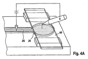
図4は、体液の試料と検査領域との接触を電気的に開始するための概念を示す。しかし、この一般概念は、通路を有する支持構造体の特別な実施形態としての皮膚貫通要素と関連させて図4に示されている。体液の転送を開始させるために、体液の試料25と担体40とのあいだに高い電圧が印加される。この事が、通路から検査領域への体液の試料の移動を引き起こす、または、担体の通路方向への移動を引き起こす。両方の場合、体液の試料によって検査領域を濡らすことは、電圧のスイッチを入れることによって非常に短い時間のあいだに開始させられる。担体の透視図から判るように、検査領域の下方の通路は、薄い毛管状通路が供給するより大量の、検査領域を濡らすための体液を供給するための集積部26に通じている。
FIG. 4 shows a concept for electrically initiating contact between a body fluid sample and an examination region. However, this general concept is illustrated in FIG. 4 in connection with a skin penetrating element as a special embodiment of a support structure having a passage. To initiate the transfer of bodily fluid, a high voltage is applied between the
図4Bは、集積部の好ましい実施形態をより詳細に示す。図から判るように、集積部26は、体液の検査領域への移動を容易にするための直立要素26’を有することが好ましい。これらの直立要素は、一方ではその端部において体液を転送するための高い電荷を誘発し、それらは、他方では体液の充填を改善する集積部26の毛管現象を向上させる。
FIG. 4B shows the preferred embodiment of the stacking portion in more detail. As can be seen, the stacking
図5A、BおよびCは、駆動することによって検査領域を通路の体液の試料と接触させることができる離間した形態の皮膚貫通要素と検査領域を備えた採取装置のデザインを示す。図5Aの実施形態は、図1に類似している。皮膚貫通要素は、毛管状通路11が設けられた内側部分13’に結合された枠を有する。内側部分と枠は、可撓部51によって連結されている。毛管状通路を充満させた後に、内側部分は、毛細管の一部が担体43下方の検査領域に接触するよう枠に対して捩られる。可撓部を中心にして曲げることによって、内側部分は、角度を持って検査領域に接触する。この事は、気泡を巻き込むことなく検査領域を均等に濡らすことができるために、とりわけ有利であることが証明されている。
FIGS. 5A, B and C show the design of a collection device with spaced-apart skin penetrating elements and test area that can be driven to contact the sample of body fluid in the passage. The embodiment of FIG. 5A is similar to FIG. The skin penetrating element has a frame coupled to an
図5Bは、担体43とその支持体が可撓部51’によって毛細管を有する主要部14’に連結されている実施形態を示す。再度述べるが、毛細管と検査領域とのあいだの接触は傾斜方式によって達成される。
FIG. 5B shows an embodiment in which the
図5Cは、二つの端部で枠部14”に連結された内側部分13”を有する実施形態を示す。圧力が内側部分13”の中央部に下側から加えられたとき、これは、担体43の下部の検査領域に向けて曲がる。再度述べるが、この内側部分を曲げることによって、傾斜した接触が達成される。
FIG. 5C shows an embodiment having an
図6は、毛管状通路の改良型形状を模式的に示す。通路の体液の充填レベルは、毛細管の幅を縮小するにしたがって一般的には増大する。図6の毛細管は、皮膚貫通要素の尖端部に通ずる第一部aを有する。拡径した第二部bは、大量の試料を供給するためである。とりわけ有用なのは、幅が縮小した第三部cである。幅が縮小されているために、充填レベルは増大し、それ故に、通路から検査領域への体液の転送は高い成功率を有する。したがって、それがまず領域cに、そして、その後に領域bに接触するよう検査領域を毛細管に傾斜方式で接触させることが好ましい。この事が、体液の転送を領域cにおいて安全に開始し、そして、検査のための充分な試料が領域bから供給されることを確実にする。領域c下流の領域dは、汚染された体液の試料またはISFを排出するために用いられる。 FIG. 6 schematically shows an improved shape of the capillary passage. The body fluid filling level of the passage generally increases as the capillary width is reduced. The capillary tube of FIG. 6 has a first part a leading to the tip of the skin penetrating element. The enlarged second part b is for supplying a large amount of sample. Particularly useful is the third part c with reduced width. Due to the reduced width, the filling level increases and therefore the transfer of body fluid from the passageway to the examination area has a high success rate. Therefore, it is preferred that the examination region is brought into contact with the capillary tube in an inclined manner so that it first contacts the region c and then the region b. This ensures that the transfer of bodily fluids begins safely in region c and that sufficient sample for testing is supplied from region b. Region d downstream of region c is used to drain contaminated body fluid samples or ISF.
図7は、尖端部に通ずる第一部aと拡径した第二部bを有する皮膚貫通要素を示す。絵Aは、皮膚に突き刺した後、血液が毛管状通路の領域aに取り込まれた状態を示す。領域bの毛管現象は低減されているために、体液の試料は、領域aを充満するが、領域bを充満はしない。皮膚貫通要素が担体43と接触させられたとき、集積部bが充満され、そして、担体43の下部の検査領域が体液の試料と接触させられるよう、いくつかの部位における開放式通路構造a,b,dはその上端が閉鎖され、そのために毛管現象がこの部位において増強される。光学要素の形状を考慮した場合、円形の検出部を有することが有利である。
FIG. 7 shows a skin-penetrating element having a first part a leading to a pointed part and an enlarged second part b. The picture A shows a state in which blood is taken into the region a of the capillary passage after piercing the skin. Since the capillary action of region b is reduced, the body fluid sample fills region a but not region b. When the skin-penetrating element is brought into contact with the
図7に示した皮膚貫通要素は、以下の方法において用いられる。
−皮膚に突き刺す
−体液の試料を毛管状通路の一部に採取する(領域a)
−領域bに体液が充填されるように、収集領域bの毛管状通路を検査領域および/または担体に接触させる
−体液からの分析物質と反応したことに起因する検査領域の変化を検出する
The skin penetrating element shown in FIG. 7 is used in the following method.
-Puncture into the skin-Collect a sample of body fluid in part of the capillary passage (region a)
-Bringing the capillary passage of the collection area b into contact with the examination area and / or the carrier so that the area b is filled with body fluid-detecting changes in the examination area due to reaction with the analyte from the body fluid
図8は、センサ45と体液通路または溝11とのあいだの接触を磁力70を用いて確立することができる概念を示す。常磁性材または強磁性材72がセンサまたは溝部13に組み込まれている、被覆されている、または取り付けられている。代案としては、適切な形状の電流搬送線が、センサまたは溝部に組み込まれているかまたは取り付けられている。
FIG. 8 illustrates the concept that a contact between the
電磁石74(または永久磁石、ソレノイド、あるいはその他の好適な手段)によって発生させられた磁界72は、したがって、センサ(または溝部あるいは両方)に駆動力70を作用させて両者を流体的に接触させる。力の大きさと、それ故に流体的接触の時間に依存した開始は、磁界強度を制御する、即ち電磁石74のスイッチを操作するまたは永久磁石を接近させることによって制御される。
The
さらに、磁力による双極子モーメントが、センサまたは溝部に被覆された非磁性リング(または類似形状の物体)に、リングの位置において時間とともに変化する磁界によって誘導される。この事は、流体的接触を開始するための駆動力を発生させる代替の方法であることを意味する。 In addition, a dipole moment due to magnetic force is induced in a non-magnetic ring (or an object of similar shape) covered with a sensor or groove by a magnetic field that varies with time at the position of the ring. This means that it is an alternative way of generating a driving force to initiate fluid contact.
図9と10に示したように、光学式インデックス一致要素80が、体液受け入れ手段82の検査領域(センサ45)を光学式検出手段(図示せず)に連結し、また、同時に体液通路11と体液受け入れ手段82のセンサ45を接触状態にするための機械的力を作用させるために用いられる。
As shown in FIGS. 9 and 10, the optical
概要を上述したように、グルコース濃度は、通路または溝11に収容されていた充分に大量な血液で濡らされたときのセンサ45の変色を速やかに測定して判定される。センサ45に適切な波長の入射光84を照射して反射光86を検出することによる反射率測定が行われる。
As outlined above, the glucose concentration is determined by quickly measuring the discoloration of the
センサ45の限定された検出領域が、濡らされた検査領域を光学式検出システムに対して位置決めするときの機械的許容誤差に厳しい制限を加える。さらに、小さい検出領域だけが使用可能な場合、センサの化学反応用酵素に内在する非等質性が、繰り返しグルコース測定に対する変動係数により重大な影響を与える。血液とセンサ45との作用開始を光学的に同時に検出するためには、作用機構の開始と光学式検出システムとのあいだに干渉があってはならない。
The limited detection area of
適切な発光器、受光器、並びにレンズおよび/または光ファイバのような構成部品から成る光学システムが、反射率測定に用いられる。センサ45から反射された特定波長の光の量が、グルコース濃度のレベルを示す。
An optical system consisting of suitable light emitters, light receivers and components such as lenses and / or optical fibers is used for reflectance measurements. The amount of light of a specific wavelength reflected from the
センサ45は、明確な光透過性を有するポリカーボネートの帯片または箔82に被覆され、入射光を乱反射する小さい粒子と混合された化学反応用酵素によりなっている。照射光84は、帯片の粒子によって散乱させられ、そして、血中グルコースとの酵素反応により活性化された色素によって吸収される。それ故に、反射光86の量は、グルコース濃度の高さに応じて増大した吸収量のために低減する。
The
エラストマ製の光学要素80は、センサ45のそれに殆ど匹敵する屈折率指数を有する。要素80は、センサ45と検出ユニットの構成部品とのあいだの中間層またはスラブとして用いられている。要素80は、センサ45(図9参照)の動作を開始するための機械的変位を変換するレバー・アームとして使用できるようにする手段88を有していてもよい。センサ45はその一方の面が要素80に当接しているが、センサの反対側の面は、エア・ギャップ92を空けておくためにスペーサ90によって溝11から離間されている。作動されたとき、体液受け入れ手段82は、下向きに曲げられ、そして、センサ42下方の微細溝11の血液はセンサに転送されて速やかな変色反応が起こる。
The
したがって、上述の構成要素は、
−血液とセンサとの接触を開始するために要素を溝11の方に駆動する手段を提供する、
−センサ45の照射と反射光強度の捕捉を同時に行うことができるようにする、
−小さいセンサ領域の光学式検出を可能にする、
−センサ表面におけるフレネル反射による干渉を低減する。
Thus, the above components are
Providing a means for driving the element towards the
-Allow the
-Enables optical detection of small sensor areas,
-Reduce interference due to Fresnel reflections on the sensor surface.
代替案としては、図10に示すように、中間適合型要素80と組み合わされた光導波管/ファイバ94が、センサ45を照射して反射光を捕捉するために用いられており、また、導波管/ファイバ94は、同時に要素80ひいてはセンサ45を体液通路または溝11に向けて変位させるよう作用する。光導波管/ファイバ90は、また、特殊コーティングによってインデックス一致要素が形成された場合、センサ45を直接作動させる。
As an alternative, as shown in FIG. 10, an optical waveguide / fiber 94 in combination with an intermediate
光導波管/ファイバの束94は、駆動機構(モータ、他の駆動ユニット、または微細サンプラーの運動を光導波管/ファイバの変位に変換する機構)によって機械的に駆動される。中間のエラストマ製器具80は、光ファイバまたは他の機械的アクチュエータの機械的変位を直接センサ45に伝動し、それにより、センサ45と血液が充填された微細体液通路11の隣接部とのあいだの作用/接触の開始のための媒介者としての役割を果たす。
The optical waveguide / fiber bundle 94 is mechanically driven by a drive mechanism (motor, other drive unit, or mechanism that converts the movement of the fine sampler into optical waveguide / fiber displacement). The intermediate
小径のファイバ96の束94は、さらに、束に含まれる各々の単一ファイバ96についての受光円錐体が開口数によって制限されているために、センサ45の小さい領域と接続するために用いられる。したがって、ファイバを高密度に集積した束は、センサの個別の小さい領域からサンプルを収集するために役に立つ。数本のファイバは、センサの濡らされた検出領域の部分から実際にサンプルを収集するが、別のファイバは、濡らされていない部分からサンプルを得る。ファイバの束は、ファイバの各々が読み出した情報から検出領域の像を形成するために配列された検出器つまりCCDに接続されている。ファイバの各々からサンプルを収集することが、小さいセンサ領域における検出を可能にし、また、機械的位置決めの許容誤差が大幅に緩和される。
The bundle 94 of
単一ファイバの各々は、センサの照明、または散乱した反射光の捕捉、または適切なビーム・スプリッタが用いられている場合には照明と同時捕捉のいずれかのために使用される。束に含まれるファイバをランダムに分散させることは、センサに均一な照明を行い、また、センサ表面全体を検出用に用いるためには望ましいことである。 Each single fiber is used for either sensor illumination or capture of scattered reflected light, or illumination and simultaneous capture if an appropriate beam splitter is used. Dispersing the fibers contained in the bundle randomly is desirable for providing uniform illumination to the sensor and for using the entire sensor surface for detection.
図11は、横方向に開かれた毛管状溝11が採取部100と、尖端部104で最初に毛細管に浸入した体液の一部を吸上げるために採取部の上流で分岐した排出部102を有する体液採取装置の一例を示す。再度述べるが、この事は、図6に関連して先に説明したように、汚染された体液の試料またはISFの排出を可能にする。体液の先頭部を受け入れるために、排出部102の毛管現象は、分岐点108の領域の入口部106の毛管現象より高いことが必要である。毛管現象を高めるために、排出部102は、蓋110によって閉鎖される。この場合、排出部の端部に排気口112を開けておくことが重要である。
FIG. 11 shows that the laterally open
図12は、排出部が延長されて、廃棄部114と、廃棄部の上流に貯留部116とを有するようにされた実施形態を示す。採取部つまり目標部100は、広く開いているために吸上げ過程において充填されない。センサ118が、採取部100と接触させられてこの部分を蓋として閉鎖したとき、毛管現象が強くなって、血液が貯留部116から採取部100に吸上げられる。したがって、排出部の容量は、採取部100を充満し、また、別途廃棄体液を吸上げておくことができるようにするために、充分に大きいことが必要である。
FIG. 12 shows an embodiment in which the discharge unit is extended to have a
図13に示すように、採取部への充填を加速するために、複数の排出部102を採用することができる。毛管現象で移動中の体液の方向を決めるために、異なる交差部形状体120を用いることができる(図14)。
As shown in FIG. 13, a plurality of
Claims (55)
体液受け入れ手段(40)と
を有し、
前記体液通路(11)の少なくとも一部が環境に開かれており、
第一の状態において前記通路(11)の体液が前記体液受け入れ手段(40)と流体的接触をしないように、前記体液受け入れ手段(40)が前記体液通路(11)から離間されている体液を採取するための装置。 A body fluid passage (11) for receiving body fluid;
Body fluid receiving means (40),
At least part of the body fluid passageway (11) is open to the environment;
The body fluid receiving means (40) is separated from the body fluid passage (11) so that the body fluid in the passage (11) is not in fluid contact with the body fluid receiving means (40) in the first state. A device for collecting.
体液受け入れ手段(40)と
を有し、
前記体液通路(11)の少なくとも一部が環境に開かれており、
前記通路の体液が前記体液受け入れ手段(40)と流体的接触をしないように、前記体液受け入れ手段(40)が前記体液通路(11)から離間されており、
前記体液受け入れ手段(40)が検査領域(45)を有している体液を分析するため装置。 A skin penetrating element (10) with a body fluid passage (11) for receiving body fluid;
Body fluid receiving means (40),
At least part of the body fluid passageway (11) is open to the environment;
The bodily fluid receiving means (40) is spaced from the bodily fluid path (11) so that the bodily fluid in the passage is not in fluid contact with the bodily fluid receiving means (40);
Device for analyzing body fluid in which the body fluid receiving means (40) has an examination region (45).
b)前記体液通路(11)からの体液が前記体液受け入れ手段(40)に接触して検査領域(45)に達するように、前記体液通路(11)を前記体液受け入れ手段(40)に接触させる工程と、
c)分析物質の濃度を特徴付ける前記検査領域(45)からの信号を受信する工程と、
d)分析物質の濃度を判定するために前記信号を処理する工程と、を有する体液中の分析物質の濃度を判定するための方法。 a) receiving bodily fluid in the bodily fluid passageway (11) of the skin penetrating element (10), preferably spatially spaced from the bodily fluid receiving means (40) during filling;
b) The bodily fluid passage (11) is brought into contact with the bodily fluid receiving means (40) so that the bodily fluid from the bodily fluid passage (11) contacts the bodily fluid receiving means (40) and reaches the examination region (45). Process,
c) receiving a signal from said examination region (45) characterizing the concentration of the analyte;
d) processing the signal to determine the concentration of the analyte, and a method for determining the concentration of the analyte in the body fluid.
体液受け入れ手段(40)と
を有し、
前記体液受け入れ手段(40)に前記排出部からの体液が接触しないように、第一の状態において前記体液受け入れ手段(40)は前記溝から離間されており、体液を受け入れるための第二の状態において前記体液受け入れ手段(40)が前記接近部に位置する体液に接触させられる分析装置。 A support structure having a groove (11) which is accessible at least in the approaching portion from the periphery, and has a body fluid introduction portion (a) and a discharge portion (d) arranged downstream of the approaching portion;
Body fluid receiving means (40),
In a first state, the body fluid receiving means (40) is separated from the groove so that the body fluid from the discharge part does not contact the body fluid receiving means (40), and a second state for receiving the body fluid. The analyzing apparatus in which the body fluid receiving means (40) is brought into contact with the body fluid located in the access portion.
体液を受け入れるために体液受け入れ手段(40)を排出部の体液部には接触させず、接近部に位置する体液には接触させる工程と
を有し、
前記体液は、周囲から接近可能であり、前記接近部の下流に配置された廃棄部(114)を有する前記支持構造体の前記接近部に充満する体液を採取するための方法。 Introducing a body fluid into the introduction part of the support structure having a groove inside;
The body fluid receiving means (40) for receiving the body fluid is not brought into contact with the body fluid part of the discharge part, but is brought into contact with the body fluid located in the approach part,
A method for collecting bodily fluid filling the access portion of the support structure, wherein the bodily fluid is accessible from the surroundings and has a waste portion (114) disposed downstream of the access portion.
前記溝から離間している体液受け入れ手段(40)と、
スイッチが入れられたとき、前記接近部からの体液を前記体液受け入れ手段(40)に転送するために、前記接近部の体液と前記体液受け入れ手段(40)とのあいだに電圧を印加する電圧源と
を有する分析装置。 A support structure that is accessible at least at the access portion from the surroundings and has a groove for receiving body fluid therein;
Body fluid receiving means (40) spaced from the groove;
A voltage source that, when switched on, applies a voltage between the bodily fluid of the approaching part and the bodily fluid receiving means (40) to transfer bodily fluid from the approaching part to the bodily fluid receiving means (40). And an analyzer.
前記接近部からの体液を前記体液受け入れ手段(40)に転送するために、前記接近部の体液と前記体液受け入れ手段(40)とのあいだに電圧を印加する工程と
を含む
支持構造体から体液受け入れ手段(40)に体液を転送するための方法。 Holding a support structure accessible at least in the access portion and having a groove for receiving bodily fluid therein in a spaced relation to the bodily fluid receiving means (40);
Applying a voltage between the body fluid in the approaching part and the body fluid receiving means (40) to transfer the body fluid from the approaching part to the body fluid receiving means (40) from the support structure to the body fluid A method for transferring bodily fluids to the receiving means (40).
前記通路の体液が体液受け入れ手段(40)と接触しないように前記体液通路(11)から離間され、また、検査領域(45)が設けられた体液受け入れ手段(40)と、
前記皮膚貫通要素(10)を前記体液受け入れ手段(40)と接触させるように転送するための転送手段と
を有する体液を分析するためのシステム。 A skin-penetrating element with a body fluid passageway (11) for receiving body fluid, at least part of which is open to the environment;
A body fluid receiving means (40) that is spaced from the body fluid passage (11) so that the body fluid in the passage does not come into contact with the body fluid receiving means (40), and is provided with an examination region (45);
A system for analyzing bodily fluid comprising transfer means for transferring the skin penetrating element (10) into contact with the bodily fluid receiving means (40).
Applications Claiming Priority (3)
| Application Number | Priority Date | Filing Date | Title |
|---|---|---|---|
| EP04005385 | 2004-03-06 | ||
| EP04005385.2 | 2004-03-06 | ||
| PCT/EP2005/002273 WO2005084530A2 (en) | 2004-03-06 | 2005-03-04 | Body fluid sampling device |
Publications (3)
| Publication Number | Publication Date |
|---|---|
| JP2007527287A true JP2007527287A (en) | 2007-09-27 |
| JP2007527287A5 JP2007527287A5 (en) | 2008-04-17 |
| JP4917013B2 JP4917013B2 (en) | 2012-04-18 |
Family
ID=34917165
Family Applications (3)
| Application Number | Title | Priority Date | Filing Date |
|---|---|---|---|
| JP2007501224A Expired - Fee Related JP4917013B2 (en) | 2004-03-06 | 2005-03-04 | Body fluid collection device |
| JP2007501232A Expired - Fee Related JP4602398B2 (en) | 2004-03-06 | 2005-03-04 | Body fluid sampling device |
| JP2007501237A Expired - Fee Related JP4959545B2 (en) | 2004-03-06 | 2005-03-07 | Body fluid sampling device and body fluid analysis system |
Family Applications After (2)
| Application Number | Title | Priority Date | Filing Date |
|---|---|---|---|
| JP2007501232A Expired - Fee Related JP4602398B2 (en) | 2004-03-06 | 2005-03-04 | Body fluid sampling device |
| JP2007501237A Expired - Fee Related JP4959545B2 (en) | 2004-03-06 | 2005-03-07 | Body fluid sampling device and body fluid analysis system |
Country Status (15)
| Country | Link |
|---|---|
| US (4) | US8000762B2 (en) |
| EP (5) | EP1722670B1 (en) |
| JP (3) | JP4917013B2 (en) |
| KR (1) | KR101198054B1 (en) |
| CN (5) | CN101690665B (en) |
| AU (2) | AU2005220022B2 (en) |
| BR (2) | BRPI0508528B8 (en) |
| CA (5) | CA2773645C (en) |
| DK (1) | DK1722670T3 (en) |
| ES (4) | ES2572775T3 (en) |
| HU (1) | HUE025706T2 (en) |
| PL (4) | PL1722670T3 (en) |
| PT (3) | PT1722670E (en) |
| SG (1) | SG153808A1 (en) |
| WO (3) | WO2005084530A2 (en) |
Cited By (13)
| Publication number | Priority date | Publication date | Assignee | Title |
|---|---|---|---|---|
| JP2009511141A (en) * | 2005-10-15 | 2009-03-19 | エフ ホフマン−ラ ロッシュ アクチェン ゲゼルシャフト | Test element and test system for testing body fluids |
| WO2010013598A1 (en) * | 2008-08-01 | 2010-02-04 | 株式会社ライトニックス | Sensor with fine needle having channel formed therein |
| JP2012515028A (en) * | 2009-01-16 | 2012-07-05 | エフ.ホフマン−ラ ロシュ アーゲー | System and method for analyzing body fluid |
| JP2014517714A (en) * | 2011-03-22 | 2014-07-24 | エフ ホフマン−ラ ロッシュ アクチェン ゲゼルシャフト | Auxiliary instrument for analysis having hydrophilic coating containing nanoparticles having silica structure |
| JP2015525882A (en) * | 2012-07-23 | 2015-09-07 | タッソ インコーポレイテッド | Methods, systems, and apparatus for open microfluidic channels |
| JP2018020173A (en) * | 2011-08-03 | 2018-02-08 | インテュイティ メディカル インコーポレイテッド | Body fluid sampling arrangements, body fluid sampling meters, and disposable cartridges |
| US10383556B2 (en) | 2008-06-06 | 2019-08-20 | Intuity Medical, Inc. | Medical diagnostic devices and methods |
| US10433780B2 (en) | 2005-09-30 | 2019-10-08 | Intuity Medical, Inc. | Devices and methods for facilitating fluid transport |
| US10441205B2 (en) | 2005-09-30 | 2019-10-15 | Intuity Medical, Inc. | Multi-site body fluid sampling and analysis cartridge |
| US10729386B2 (en) | 2013-06-21 | 2020-08-04 | Intuity Medical, Inc. | Analyte monitoring system with audible feedback |
| US11002743B2 (en) | 2009-11-30 | 2021-05-11 | Intuity Medical, Inc. | Calibration material delivery devices and methods |
| US11399744B2 (en) | 2008-06-06 | 2022-08-02 | Intuity Medical, Inc. | Detection meter and mode of operation |
| US11419532B2 (en) | 2005-06-13 | 2022-08-23 | Intuity Medical, Inc. | Analyte detection devices and methods with hematocrit/volume correction and feedback control |
Families Citing this family (137)
| Publication number | Priority date | Publication date | Assignee | Title |
|---|---|---|---|---|
| US6391005B1 (en) | 1998-03-30 | 2002-05-21 | Agilent Technologies, Inc. | Apparatus and method for penetration with shaft having a sensor for sensing penetration depth |
| US8641644B2 (en) | 2000-11-21 | 2014-02-04 | Sanofi-Aventis Deutschland Gmbh | Blood testing apparatus having a rotatable cartridge with multiple lancing elements and testing means |
| US9226699B2 (en) | 2002-04-19 | 2016-01-05 | Sanofi-Aventis Deutschland Gmbh | Body fluid sampling module with a continuous compression tissue interface surface |
| US8337419B2 (en) | 2002-04-19 | 2012-12-25 | Sanofi-Aventis Deutschland Gmbh | Tissue penetration device |
| WO2002100460A2 (en) | 2001-06-12 | 2002-12-19 | Pelikan Technologies, Inc. | Electric lancet actuator |
| WO2002100251A2 (en) | 2001-06-12 | 2002-12-19 | Pelikan Technologies, Inc. | Self optimizing lancing device with adaptation means to temporal variations in cutaneous properties |
| US9427532B2 (en) | 2001-06-12 | 2016-08-30 | Sanofi-Aventis Deutschland Gmbh | Tissue penetration device |
| US7981056B2 (en) | 2002-04-19 | 2011-07-19 | Pelikan Technologies, Inc. | Methods and apparatus for lancet actuation |
| EP1404235A4 (en) | 2001-06-12 | 2008-08-20 | Pelikan Technologies Inc | METHOD AND APPARATUS FOR INTEGRATED LANCET LAUNCH DEVICE ON BLOOD SAMPLING CARTRIDGE |
| US7041068B2 (en) | 2001-06-12 | 2006-05-09 | Pelikan Technologies, Inc. | Sampling module device and method |
| US9795747B2 (en) | 2010-06-02 | 2017-10-24 | Sanofi-Aventis Deutschland Gmbh | Methods and apparatus for lancet actuation |
| US7004928B2 (en) | 2002-02-08 | 2006-02-28 | Rosedale Medical, Inc. | Autonomous, ambulatory analyte monitor or drug delivery device |
| US10022078B2 (en) | 2004-07-13 | 2018-07-17 | Dexcom, Inc. | Analyte sensor |
| US7297122B2 (en) | 2002-04-19 | 2007-11-20 | Pelikan Technologies, Inc. | Method and apparatus for penetrating tissue |
| US7547287B2 (en) | 2002-04-19 | 2009-06-16 | Pelikan Technologies, Inc. | Method and apparatus for penetrating tissue |
| US7901362B2 (en) | 2002-04-19 | 2011-03-08 | Pelikan Technologies, Inc. | Method and apparatus for penetrating tissue |
| US7713214B2 (en) | 2002-04-19 | 2010-05-11 | Pelikan Technologies, Inc. | Method and apparatus for a multi-use body fluid sampling device with optical analyte sensing |
| US7909778B2 (en) | 2002-04-19 | 2011-03-22 | Pelikan Technologies, Inc. | Method and apparatus for penetrating tissue |
| US8579831B2 (en) | 2002-04-19 | 2013-11-12 | Sanofi-Aventis Deutschland Gmbh | Method and apparatus for penetrating tissue |
| US7331931B2 (en) | 2002-04-19 | 2008-02-19 | Pelikan Technologies, Inc. | Method and apparatus for penetrating tissue |
| US8221334B2 (en) | 2002-04-19 | 2012-07-17 | Sanofi-Aventis Deutschland Gmbh | Method and apparatus for penetrating tissue |
| US8702624B2 (en) | 2006-09-29 | 2014-04-22 | Sanofi-Aventis Deutschland Gmbh | Analyte measurement device with a single shot actuator |
| US7976476B2 (en) | 2002-04-19 | 2011-07-12 | Pelikan Technologies, Inc. | Device and method for variable speed lancet |
| US9314194B2 (en) | 2002-04-19 | 2016-04-19 | Sanofi-Aventis Deutschland Gmbh | Tissue penetration device |
| US9248267B2 (en) | 2002-04-19 | 2016-02-02 | Sanofi-Aventis Deustchland Gmbh | Tissue penetration device |
| US7232451B2 (en) | 2002-04-19 | 2007-06-19 | Pelikan Technologies, Inc. | Method and apparatus for penetrating tissue |
| US8360992B2 (en) | 2002-04-19 | 2013-01-29 | Sanofi-Aventis Deutschland Gmbh | Method and apparatus for penetrating tissue |
| US7175642B2 (en) | 2002-04-19 | 2007-02-13 | Pelikan Technologies, Inc. | Methods and apparatus for lancet actuation |
| US7229458B2 (en) | 2002-04-19 | 2007-06-12 | Pelikan Technologies, Inc. | Method and apparatus for penetrating tissue |
| US8267870B2 (en) | 2002-04-19 | 2012-09-18 | Sanofi-Aventis Deutschland Gmbh | Method and apparatus for body fluid sampling with hybrid actuation |
| US7892183B2 (en) | 2002-04-19 | 2011-02-22 | Pelikan Technologies, Inc. | Method and apparatus for body fluid sampling and analyte sensing |
| US7674232B2 (en) | 2002-04-19 | 2010-03-09 | Pelikan Technologies, Inc. | Method and apparatus for penetrating tissue |
| US8784335B2 (en) | 2002-04-19 | 2014-07-22 | Sanofi-Aventis Deutschland Gmbh | Body fluid sampling device with a capacitive sensor |
| US9795334B2 (en) | 2002-04-19 | 2017-10-24 | Sanofi-Aventis Deutschland Gmbh | Method and apparatus for penetrating tissue |
| US8372016B2 (en) | 2002-04-19 | 2013-02-12 | Sanofi-Aventis Deutschland Gmbh | Method and apparatus for body fluid sampling and analyte sensing |
| US7491178B2 (en) | 2002-04-19 | 2009-02-17 | Pelikan Technologies, Inc. | Method and apparatus for penetrating tissue |
| US7815579B2 (en) | 2005-03-02 | 2010-10-19 | Roche Diagnostics Operations, Inc. | Dynamic integrated lancing test strip with sterility cover |
| WO2004060162A1 (en) | 2002-12-30 | 2004-07-22 | Roche Diagnostics Gmbh | Flexible test strip lancet device |
| US7214200B2 (en) | 2002-12-30 | 2007-05-08 | Roche Diagnostics Operations, Inc. | Integrated analytical test element |
| US8574895B2 (en) | 2002-12-30 | 2013-11-05 | Sanofi-Aventis Deutschland Gmbh | Method and apparatus using optical techniques to measure analyte levels |
| US7052652B2 (en) | 2003-03-24 | 2006-05-30 | Rosedale Medical, Inc. | Analyte concentration detection devices and methods |
| DE602004028463D1 (en) | 2003-05-30 | 2010-09-16 | Pelikan Technologies Inc | METHOD AND DEVICE FOR INJECTING LIQUID |
| EP1633235B1 (en) | 2003-06-06 | 2014-05-21 | Sanofi-Aventis Deutschland GmbH | Apparatus for body fluid sampling and analyte sensing |
| WO2006001797A1 (en) | 2004-06-14 | 2006-01-05 | Pelikan Technologies, Inc. | Low pain penetrating |
| US7920906B2 (en) | 2005-03-10 | 2011-04-05 | Dexcom, Inc. | System and methods for processing analyte sensor data for sensor calibration |
| US8282576B2 (en) | 2003-09-29 | 2012-10-09 | Sanofi-Aventis Deutschland Gmbh | Method and apparatus for an improved sample capture device |
| US9351680B2 (en) | 2003-10-14 | 2016-05-31 | Sanofi-Aventis Deutschland Gmbh | Method and apparatus for a variable user interface |
| US9247900B2 (en) | 2004-07-13 | 2016-02-02 | Dexcom, Inc. | Analyte sensor |
| US7822454B1 (en) | 2005-01-03 | 2010-10-26 | Pelikan Technologies, Inc. | Fluid sampling device with improved analyte detecting member configuration |
| WO2005065414A2 (en) | 2003-12-31 | 2005-07-21 | Pelikan Technologies, Inc. | Method and apparatus for improving fluidic flow and sample capture |
| PT1722670E (en) | 2004-03-06 | 2013-11-27 | Hoffmann La Roche | Body fluid sampling device |
| US7819822B2 (en) | 2004-03-06 | 2010-10-26 | Roche Diagnostics Operations, Inc. | Body fluid sampling device |
| EP1751546A2 (en) | 2004-05-20 | 2007-02-14 | Albatros Technologies GmbH & Co. KG | Printable hydrogel for biosensors |
| US9775553B2 (en) | 2004-06-03 | 2017-10-03 | Sanofi-Aventis Deutschland Gmbh | Method and apparatus for a fluid sampling device |
| EP1765194A4 (en) | 2004-06-03 | 2010-09-29 | Pelikan Technologies Inc | METHOD AND APPARATUS FOR MANUFACTURING A DEVICE FOR SAMPLING LIQUIDS |
| US9044199B2 (en) | 2004-07-13 | 2015-06-02 | Dexcom, Inc. | Transcutaneous analyte sensor |
| US7488298B2 (en) | 2004-10-08 | 2009-02-10 | Roche Diagnostics Operations, Inc. | Integrated lancing test strip with capillary transfer sheet |
| EP1654985A1 (en) * | 2004-11-09 | 2006-05-10 | F. Hoffmann-La Roche Ag | Sampling device for sample liquid |
| WO2006072004A2 (en) * | 2004-12-30 | 2006-07-06 | Pelikan Technologies, Inc. | Method and apparatus for analyte measurement test time |
| US8652831B2 (en) * | 2004-12-30 | 2014-02-18 | Sanofi-Aventis Deutschland Gmbh | Method and apparatus for analyte measurement test time |
| EP1759633A1 (en) | 2005-09-01 | 2007-03-07 | F.Hoffmann-La Roche Ag | Device for sampling bodily fluids and its fabrication method |
| EP1839576A1 (en) | 2006-03-29 | 2007-10-03 | F.Hoffmann-La Roche Ag | Test system with test unit for analysing body fluids |
| US20090093735A1 (en) * | 2006-03-29 | 2009-04-09 | Stephan Korner | Test unit and test system for analyzing body fluids |
| EP1878386A1 (en) | 2006-07-15 | 2008-01-16 | Roche Diagnostics GmbH | Process to produce lancet; lancet, lancet band and device for pricking the skin |
| EP1878387B1 (en) | 2006-07-15 | 2010-11-24 | Roche Diagnostics GmbH | Lancet, lancet feeder belt and pricking device for creating a puncture wound |
| PL1880671T3 (en) * | 2006-07-18 | 2011-03-31 | Hoffmann La Roche | Lancet wheel |
| EP1894526A1 (en) * | 2006-09-04 | 2008-03-05 | F. Hoffmann-la Roche AG | Lancet |
| US8852124B2 (en) * | 2006-10-13 | 2014-10-07 | Roche Diagnostics Operations, Inc. | Tape transport lance sampler |
| EP1911394B1 (en) | 2006-10-14 | 2009-05-06 | Roche Diagnostics GmbH | Lancet with capillar channel |
| EP1977686A1 (en) * | 2007-04-04 | 2008-10-08 | F.Hoffmann-La Roche Ag | Disposable diagnostic article |
| US20110092854A1 (en) | 2009-10-20 | 2011-04-21 | Uwe Kraemer | Instruments and system for producing a sample of a body fluid and for analysis thereof |
| MX2009011627A (en) | 2007-04-30 | 2009-11-10 | Hoffmann La Roche | Instrument and system for producing a sample of a body liquid and for analysis thereof. |
| CN101754812B (en) | 2007-05-04 | 2013-06-26 | 克拉洛诊断仪器公司 | Fluidic Connectors and Microfluidic Systems |
| WO2008145625A2 (en) | 2007-05-29 | 2008-12-04 | Roche Diagnostics Gmbh | Test system for measuring the concentration of an analyte in a body fluid |
| EP2025287A1 (en) * | 2007-08-16 | 2009-02-18 | F.Hoffmann-La Roche Ag | Diagnostic disposable part and method for its production |
| ES2376025T3 (en) * | 2007-09-17 | 2012-03-08 | F. Hoffmann-La Roche Ag | ONE-USE DEVICE FOR ANALYZING A BODY FLUID. |
| EP2205153B1 (en) | 2007-10-08 | 2017-04-19 | Roche Diabetes Care GmbH | Analysis system for automatic skin prick analysis |
| DE502007005693D1 (en) * | 2007-10-12 | 2010-12-30 | Roche Diagnostics Gmbh | Test tape device for examining a body fluid |
| KR101009447B1 (en) * | 2007-11-12 | 2011-01-19 | 바디텍메드 주식회사 | Body fluid sampling, pretreatment and dosing device and method |
| AU2013202929B2 (en) * | 2008-01-28 | 2016-05-26 | F. Hoffmann-La Roche Ag | System for detection of an analyte in a body fluid |
| US7766846B2 (en) * | 2008-01-28 | 2010-08-03 | Roche Diagnostics Operations, Inc. | Rapid blood expression and sampling |
| EP2087840A1 (en) * | 2008-02-11 | 2009-08-12 | F.Hoffmann-La Roche Ag | Device and method for removing bodily fluids |
| EP2093284A1 (en) | 2008-02-19 | 2009-08-26 | F.Hoffmann-La Roche Ag | Stabilisation of dehydrogenases with stable coenzymes |
| WO2009105709A1 (en) | 2008-02-21 | 2009-08-27 | Dexcom, Inc. | Systems and methods for processing, transmitting and displaying sensor data |
| CA2717894C (en) * | 2008-03-05 | 2014-05-27 | Becton, Dickinson And Company | Capillary action collection device and container assembly |
| US9386944B2 (en) | 2008-04-11 | 2016-07-12 | Sanofi-Aventis Deutschland Gmbh | Method and apparatus for analyte detecting device |
| USD586916S1 (en) | 2008-05-09 | 2009-02-17 | Lifescan Scotland, Ltd. | Handheld lancing device |
| USD586465S1 (en) | 2008-05-09 | 2009-02-10 | Lifescan Scotland Limited | Handheld lancing device |
| CA2725264C (en) | 2008-05-30 | 2017-06-20 | Intuity Medical, Inc. | Body fluid sampling device -- sampling site interface |
| US8118824B2 (en) * | 2008-09-16 | 2012-02-21 | Roche Diagnostics Operations, Inc. | Magnetic powered lancing drive |
| EP2181651A1 (en) | 2008-10-29 | 2010-05-05 | Roche Diagnostics GmbH | Instrument and system for producing a sample of a body liquid and for analysis thereof |
| PL2359136T3 (en) * | 2008-11-07 | 2019-07-31 | F. Hoffmann-La Roche Ag | Fine-grained filler substances for photometric reaction films |
| US9375169B2 (en) | 2009-01-30 | 2016-06-28 | Sanofi-Aventis Deutschland Gmbh | Cam drive for managing disposable penetrating member actions with a single motor and motor and control system |
| US8221700B2 (en) | 2009-02-02 | 2012-07-17 | Opko Diagnostics, Llc | Structures for controlling light interaction with microfluidic devices |
| EP2218400A1 (en) | 2009-02-12 | 2010-08-18 | Roche Diagnostics GmbH | Lance with test area |
| EP2398909B1 (en) | 2009-02-19 | 2015-07-22 | F. Hoffmann-La Roche AG | Fast reaction kinetics of enzymes having low activity in dry chemistry layers |
| KR101604624B1 (en) | 2009-02-19 | 2016-03-28 | 에프. 호프만-라 로슈 아게 | Fast reaction kinetics of enzymes having low activity in dry chemistry layers |
| EP2241252A1 (en) * | 2009-03-17 | 2010-10-20 | F. Hoffmann-La Roche AG | Testing device, in particular for blood sugar tests |
| US9176090B2 (en) | 2009-04-07 | 2015-11-03 | Panasonic Healthcare Holdings Co., Ltd. | Sensor chip, and measurement device and blood test device in which this sensor chip is used |
| EP2263526A1 (en) | 2009-06-19 | 2010-12-22 | Roche Diagnostics GmbH | Piercing system |
| EP2272429A1 (en) | 2009-07-10 | 2011-01-12 | Roche Diagnostics GmbH | Lancet |
| EP2283774A1 (en) | 2009-08-13 | 2011-02-16 | Roche Diagnostics GmbH | Test element for analysing a body fluid |
| EP2287605A1 (en) | 2009-08-20 | 2011-02-23 | Roche Diagnostics GmbH | Simplified magazining of integrated systems |
| EP2322924A1 (en) | 2009-10-15 | 2011-05-18 | F. Hoffmann-La Roche AG | Protection from hydrophobic agents |
| WO2011048200A2 (en) | 2009-10-22 | 2011-04-28 | Roche Diagnostics Gmbh | Micro-capillary system having increased sample volume |
| CN102068262B (en) * | 2009-11-23 | 2012-11-21 | 财团法人金属工业研究发展中心 | Sampling device with flexible compression zone |
| EP2333544A1 (en) | 2009-12-11 | 2011-06-15 | F. Hoffmann-La Roche AG | Sterilisable chemistry for test elements |
| KR101506928B1 (en) | 2009-12-16 | 2015-03-30 | 에프. 호프만-라 로슈 아게 | Detecting the decomposition of enzymes in a test element by means of controlled release of protected analyte |
| US8965476B2 (en) | 2010-04-16 | 2015-02-24 | Sanofi-Aventis Deutschland Gmbh | Tissue penetration device |
| EP2382921A1 (en) | 2010-04-30 | 2011-11-02 | Roche Diagnostics GmbH | Lancing device with automatic disengagement |
| EP2584964B1 (en) | 2010-06-25 | 2021-08-04 | Intuity Medical, Inc. | Analyte monitoring devices |
| EP2417910B1 (en) | 2010-08-11 | 2013-06-26 | Roche Diagnostics GmbH | Analytical test unit and test system |
| TWI532530B (en) * | 2010-10-29 | 2016-05-11 | 萬國商業機器公司 | Multilayer microfluidic probe head with immersion channels and fabrication thereof |
| EP2520225B1 (en) | 2011-05-06 | 2014-05-21 | Roche Diagnostics GmbH | Lancet |
| EP2757953B1 (en) * | 2011-09-23 | 2015-07-29 | Roche Diagnostics GmbH | Method for the mask-etching of a piercing element |
| US20130211289A1 (en) | 2012-01-25 | 2013-08-15 | Tasso, Inc. | Handheld Device for Drawing, Collecting, and Analyzing Bodily Fluid |
| EA030682B1 (en) | 2012-03-05 | 2018-09-28 | Ой Арктик Партнерс Аб | METHODS AND DEVICES FOR PREDICTING THE RISK OF PROSTATE CANCER AND VOLUME OF THE PROSTATE |
| SG11201501676QA (en) * | 2012-09-06 | 2015-04-29 | Theranos Inc | Systems, devices, and methods for bodily fluid sample collection |
| US20150320348A1 (en) * | 2012-11-16 | 2015-11-12 | Lightstat, Llc | Disposable sample collection method and apparatus |
| EP2777499B1 (en) * | 2013-03-15 | 2015-09-16 | Ortho-Clinical Diagnostics Inc | Rotatable fluid sample collection device |
| US9523653B2 (en) | 2013-05-09 | 2016-12-20 | Changsha Sinocare Inc. | Disposable test sensor with improved sampling entrance |
| US9518951B2 (en) | 2013-12-06 | 2016-12-13 | Changsha Sinocare Inc. | Disposable test sensor with improved sampling entrance |
| US9897566B2 (en) | 2014-01-13 | 2018-02-20 | Changsha Sinocare Inc. | Disposable test sensor |
| TWI548395B (en) * | 2014-01-28 | 2016-09-11 | 微凸科技股份有限公司 | Continuous percutaneous microneedle monitoring system |
| US9939401B2 (en) | 2014-02-20 | 2018-04-10 | Changsha Sinocare Inc. | Test sensor with multiple sampling routes |
| US10779757B2 (en) * | 2014-08-01 | 2020-09-22 | Tasso, Inc. | Devices, systems and methods for gravity-enhanced microfluidic collection, handling and transferring of fluids |
| EP3769682B1 (en) | 2014-08-01 | 2024-01-03 | Tasso, Inc. | Systems for gravity-enhanced microfluidic collection, handling and transferring of fluids |
| CN104874098B (en) * | 2015-04-08 | 2018-04-10 | 上海交通大学 | A kind of hollow metal micropin and its batch preparation |
| CN105738462A (en) * | 2016-02-24 | 2016-07-06 | 长沙金域医学检验所有限公司 | Detection method for microelements in peripheral blood |
| US11147485B2 (en) * | 2016-05-04 | 2021-10-19 | Midge Medical Gmbh | Body fluid extraction device |
| CN106137223B (en) * | 2016-08-12 | 2019-04-26 | 上海移宇科技股份有限公司 | One-step fully integrated body fluid sampling analyzer |
| US10596591B2 (en) * | 2017-01-04 | 2020-03-24 | Red Devil Inc. | Material dispensing system and method |
| CN108968982B (en) * | 2018-06-07 | 2024-08-02 | 杭州博拓生物科技股份有限公司 | Device for detecting analyte in sample |
| USD967402S1 (en) * | 2019-06-05 | 2022-10-18 | Aidian Oy | Blood collecting device |
| CN111272849B (en) * | 2019-08-20 | 2024-02-27 | 深圳硅基传感科技有限公司 | Working electrode of glucose sensor and preparation method thereof |
| CN111956237B (en) * | 2020-07-31 | 2023-03-24 | 江苏麦酷博信息科技有限公司 | RFID blood collection card |
| US12054334B2 (en) | 2021-11-19 | 2024-08-06 | Red Devil, Inc. | Sausage package dispensing system, device and method |
Citations (2)
| Publication number | Priority date | Publication date | Assignee | Title |
|---|---|---|---|---|
| JPH04231842A (en) * | 1990-05-22 | 1992-08-20 | Eastman Kodak Co | Small-capacity-serum distributing type unitary-needle blood sampling apparatus |
| JP2004522146A (en) * | 2000-12-19 | 2004-07-22 | インバネス・メディカル・リミテッド | Apparatus and method for measuring blood coagulation |
Family Cites Families (95)
| Publication number | Priority date | Publication date | Assignee | Title |
|---|---|---|---|---|
| US6268A (en) * | 1849-04-03 | James h | ||
| US2728343A (en) | 1954-06-03 | 1955-12-27 | S & R J Everett & Co Ltd | Sewing needles |
| SE388280B (en) | 1972-04-28 | 1976-09-27 | Harco Electr Ltd | APPLIANCE FOR QUANTITY SATURATION OF FLUID IN PROVREMSOR |
| US4218421A (en) | 1978-08-18 | 1980-08-19 | Honeywell Inc. | Disposable container for a continuous band of test strips |
| US4627445A (en) | 1985-04-08 | 1986-12-09 | Garid, Inc. | Glucose medical monitoring system |
| US4935346A (en) * | 1986-08-13 | 1990-06-19 | Lifescan, Inc. | Minimum procedure system for the determination of analytes |
| US5077010A (en) | 1987-07-15 | 1991-12-31 | Fuji Photo Film Co., Ltd. | Long-test-film cassette for biochemical analysis, and system for loading the same |
| USRE36268E (en) | 1988-03-15 | 1999-08-17 | Boehringer Mannheim Corporation | Method and apparatus for amperometric diagnostic analysis |
| US4995402A (en) * | 1988-10-12 | 1991-02-26 | Thorne, Smith, Astill Technologies, Inc. | Medical droplet whole blood and like monitoring |
| JPH0810207B2 (en) * | 1989-11-08 | 1996-01-31 | 日本特殊陶業株式会社 | Biosensor |
| US5172701A (en) | 1990-02-28 | 1992-12-22 | Medical Device Technologies, Inc. | Single use automated soft tissue aspiration biopsy device |
| US5163442A (en) * | 1991-07-30 | 1992-11-17 | Harry Ono | Finger tip blood collector |
| DE4212315A1 (en) | 1992-04-13 | 1993-10-14 | Boehringer Mannheim Gmbh | Blood lancet device for drawing blood for diagnostic purposes |
| US5318514A (en) * | 1992-08-17 | 1994-06-07 | Btx, Inc. | Applicator for the electroporation of drugs and genes into surface cells |
| US5582184A (en) * | 1993-10-13 | 1996-12-10 | Integ Incorporated | Interstitial fluid collection and constituent measurement |
| US5762770A (en) | 1994-02-21 | 1998-06-09 | Boehringer Mannheim Corporation | Electrochemical biosensor test strip |
| US5591139A (en) * | 1994-06-06 | 1997-01-07 | The Regents Of The University Of California | IC-processed microneedles |
| US5644177A (en) * | 1995-02-23 | 1997-07-01 | Wisconsin Alumni Research Foundation | Micromechanical magnetically actuated devices |
| CN1207056A (en) * | 1995-11-13 | 1999-02-03 | 科特克斯(英国)有限公司 | Diagnostic Test Equipment |
| AU731250B2 (en) * | 1995-11-13 | 2001-03-29 | Cortecs (Uk) Limited | Diagnostic test apparatus |
| US5801057A (en) * | 1996-03-22 | 1998-09-01 | Smart; Wilson H. | Microsampling device and method of construction |
| WO1997042886A1 (en) | 1996-05-17 | 1997-11-20 | Mercury Diagnostics, Inc. | Body fluid sampling device and methods of use |
| AU3880697A (en) | 1996-07-03 | 1998-01-21 | Altea Technologies, Inc. | Multiple mechanical microporation of skin or mucosa |
| US6486947B2 (en) * | 1998-07-22 | 2002-11-26 | Ljl Biosystems, Inc. | Devices and methods for sample analysis |
| US5931794A (en) | 1997-10-21 | 1999-08-03 | Pitesky; Isadore | Allergy testing apparatus |
| DE19824036A1 (en) * | 1997-11-28 | 1999-06-02 | Roche Diagnostics Gmbh | Analytical measuring device with lancing device |
| US6063040A (en) * | 1998-01-16 | 2000-05-16 | Specialized Health Products, Inc. | Self retracting needle apparatus and method for phlebotomy |
| SG102538A1 (en) * | 1998-04-24 | 2004-03-26 | Roche Diagnostics Gmbh | Storage container for analytical devices |
| US6214030B1 (en) | 1998-08-10 | 2001-04-10 | Mani, Inc. | Suture needle |
| US6132449A (en) * | 1999-03-08 | 2000-10-17 | Agilent Technologies, Inc. | Extraction and transportation of blood for analysis |
| US6660018B2 (en) * | 1999-03-08 | 2003-12-09 | Agilent Technologies, Inc. | Multiple lancet device |
| US6368563B1 (en) * | 1999-03-12 | 2002-04-09 | Integ, Inc. | Collection well for body fluid tester |
| US6252195B1 (en) | 1999-04-26 | 2001-06-26 | Ethicon, Inc. | Method of forming blind holes in surgical needles using a diode pumped Nd-YAG laser |
| EP1078602A3 (en) | 1999-08-26 | 2001-04-04 | Mani, Inc. | Suturing needle for medical use |
| US6364889B1 (en) | 1999-11-17 | 2002-04-02 | Bayer Corporation | Electronic lancing device |
| US7499745B2 (en) | 2000-02-28 | 2009-03-03 | Barbara Ann Karmanos Cancer Institute | Multidimensional bioelectrical tissue analyzer |
| US6551838B2 (en) * | 2000-03-02 | 2003-04-22 | Microchips, Inc. | Microfabricated devices for the storage and selective exposure of chemicals and devices |
| DE10010694A1 (en) | 2000-03-04 | 2001-09-06 | Roche Diagnostics Gmbh | Lancet including tipped needle with body surrounding tip |
| US6612111B1 (en) * | 2000-03-27 | 2003-09-02 | Lifescan, Inc. | Method and device for sampling and analyzing interstitial fluid and whole blood samples |
| US6506168B1 (en) * | 2000-05-26 | 2003-01-14 | Abbott Laboratories | Apparatus and method for obtaining blood for diagnostic tests |
| DE10026172A1 (en) | 2000-05-26 | 2001-11-29 | Roche Diagnostics Gmbh | Body fluid withdrawal system |
| AU2001275138A1 (en) * | 2000-06-02 | 2001-12-17 | The University Of Utah Research Foundation | Active needle devices with integrated functionality |
| US6540675B2 (en) * | 2000-06-27 | 2003-04-01 | Rosedale Medical, Inc. | Analyte monitor |
| WO2002007503A1 (en) | 2000-07-25 | 2002-01-31 | The Regents Of The University Of California | Electrowetting-driven micropumping |
| US6773566B2 (en) * | 2000-08-31 | 2004-08-10 | Nanolytics, Inc. | Electrostatic actuators for microfluidics and methods for using same |
| EP1203563A3 (en) | 2000-10-31 | 2004-01-02 | Boehringer Mannheim Gmbh | Analyzing mean with integrated lancet |
| DE60103924T2 (en) | 2000-11-06 | 2005-07-14 | Nanostream, Inc., Pasadena | MICROFLUID FLOW RATE DEVICE |
| US6638246B1 (en) | 2000-11-28 | 2003-10-28 | Scimed Life Systems, Inc. | Medical device for delivery of a biologically active material to a lumen |
| WO2002064193A2 (en) | 2000-12-14 | 2002-08-22 | Georgia Tech Research Corporation | Microneedle devices and production thereof |
| DE10105549A1 (en) * | 2001-02-06 | 2002-08-29 | Roche Diagnostics Gmbh | System for monitoring the concentration of analytes in body fluids |
| KR100398309B1 (en) * | 2001-02-20 | 2003-09-19 | 한국과학기술원 | Micropump actuated by the movement of liquid drop induced by continuous electrowetting |
| WO2002100274A1 (en) * | 2001-06-08 | 2002-12-19 | Hoffmann-La Roche Ag | Bodily fluid sampling device and test media cassette to be used with such a device |
| US7001344B2 (en) * | 2001-06-12 | 2006-02-21 | Pelikan Technologies, Inc. | Blood sampling device with diaphragm actuated lancet |
| US6875613B2 (en) | 2001-06-12 | 2005-04-05 | Lifescan, Inc. | Biological fluid constituent sampling and measurement devices and methods |
| US6793632B2 (en) | 2001-06-12 | 2004-09-21 | Lifescan, Inc. | Percutaneous biological fluid constituent sampling and measurement devices and methods |
| US6837988B2 (en) | 2001-06-12 | 2005-01-04 | Lifescan, Inc. | Biological fluid sampling and analyte measurement devices and methods |
| US7041068B2 (en) * | 2001-06-12 | 2006-05-09 | Pelikan Technologies, Inc. | Sampling module device and method |
| DE10134650B4 (en) | 2001-07-20 | 2009-12-03 | Roche Diagnostics Gmbh | System for taking small amounts of body fluid |
| US20030028087A1 (en) | 2001-08-01 | 2003-02-06 | Yuzhakov Vadim Vladimirovich | Devices for analyte concentration determination and methods of using the same |
| US20030028125A1 (en) | 2001-08-06 | 2003-02-06 | Yuzhakov Vadim V. | Physiological sample collection devices and methods of using the same |
| SE0102736D0 (en) | 2001-08-14 | 2001-08-14 | Patrick Griss | Side opened out-of-plane microneedles for microfluidic transdermal interfacing and fabrication process of side opened out-of-plane microneedles |
| US6966880B2 (en) * | 2001-10-16 | 2005-11-22 | Agilent Technologies, Inc. | Universal diagnostic platform |
| US7311708B2 (en) | 2001-12-12 | 2007-12-25 | Tissuelink Medical, Inc. | Fluid-assisted medical devices, systems and methods |
| US6840909B2 (en) | 2002-03-25 | 2005-01-11 | Acueity, Inc. | Apparatus and method for intraductal cytology |
| US7175642B2 (en) * | 2002-04-19 | 2007-02-13 | Pelikan Technologies, Inc. | Methods and apparatus for lancet actuation |
| US7343188B2 (en) | 2002-05-09 | 2008-03-11 | Lifescan, Inc. | Devices and methods for accessing and analyzing physiological fluid |
| US20030212344A1 (en) * | 2002-05-09 | 2003-11-13 | Vadim Yuzhakov | Physiological sample collection devices and methods of using the same |
| US20030143113A2 (en) | 2002-05-09 | 2003-07-31 | Lifescan, Inc. | Physiological sample collection devices and methods of using the same |
| DE60317197T2 (en) | 2002-05-31 | 2008-08-07 | Facet Technologies, Llc | PRECISE GUIDED LANZETTE |
| US20030223906A1 (en) | 2002-06-03 | 2003-12-04 | Mcallister Devin | Test strip container system |
| EP1371419A1 (en) * | 2002-06-12 | 2003-12-17 | F. Hoffmann-La Roche AG | Method and device for detecting the presence of an analyte in a test sample |
| CA2497282A1 (en) | 2002-07-26 | 2004-02-05 | Stuart Brown | Tissue and fluid sampling device |
| US7241420B2 (en) * | 2002-08-05 | 2007-07-10 | Palo Alto Research Center Incorporated | Capillary-channel probes for liquid pickup, transportation and dispense using stressy metal |
| US8062573B2 (en) | 2002-09-16 | 2011-11-22 | Theraject, Inc. | Solid micro-perforators and methods of use |
| US6989234B2 (en) * | 2002-09-24 | 2006-01-24 | Duke University | Method and apparatus for non-contact electrostatic actuation of droplets |
| US7192405B2 (en) | 2002-09-30 | 2007-03-20 | Becton, Dickinson And Company | Integrated lancet and bodily fluid sensor |
| EP1424040A1 (en) | 2002-11-26 | 2004-06-02 | Roche Diagnostics GmbH | Body fluid testing device |
| US20040193072A1 (en) * | 2003-03-28 | 2004-09-30 | Allen John J. | Method of analyte measurement using integrated lance and strip |
| EP1635700B1 (en) * | 2003-06-13 | 2016-03-09 | Sanofi-Aventis Deutschland GmbH | Apparatus for a point of care device |
| DE10327683A1 (en) | 2003-06-20 | 2005-01-20 | Bayer Technology Services Gmbh | Method and device for the quantitative electrical detection of analytes |
| US20050043597A1 (en) * | 2003-07-31 | 2005-02-24 | Skymoon Research And Development, Llc | Optical vivo probe of analyte concentration within the sterile matrix under the human nail |
| US7223248B2 (en) | 2003-08-13 | 2007-05-29 | Lifescan, Inc. | Packaged medical device with a deployable dermal tissue penetration member |
| US7361182B2 (en) * | 2003-12-19 | 2008-04-22 | Lightnix, Inc. | Medical lancet |
| US7410590B2 (en) * | 2003-12-19 | 2008-08-12 | Palo Alto Research Center Incorporated | Transferable micro spring structure |
| PT1722670E (en) * | 2004-03-06 | 2013-11-27 | Hoffmann La Roche | Body fluid sampling device |
| US7819822B2 (en) * | 2004-03-06 | 2010-10-26 | Roche Diagnostics Operations, Inc. | Body fluid sampling device |
| US7351213B2 (en) * | 2004-04-15 | 2008-04-01 | Roche Diagnostics Operation, Inc. | Integrated spot monitoring device with fluid sensor |
| EP1771112A2 (en) * | 2004-07-20 | 2007-04-11 | Bayer HealthCare LLC | Multiple tip lancet |
| US20060047309A1 (en) | 2004-08-25 | 2006-03-02 | Cichocki Frank R Jr | Metal injection molded suture needles |
| JP2006119401A (en) | 2004-10-22 | 2006-05-11 | Seiko Epson Corp | Method and apparatus for manufacturing electro-optical device, electro-optical device, and electronic apparatus |
| US7771803B2 (en) * | 2004-10-27 | 2010-08-10 | Palo Alto Research Center Incorporated | Oblique parts or surfaces |
| US20070270738A1 (en) | 2005-04-25 | 2007-11-22 | Wu Jeffrey M | Method of treating ACNE with stratum corneum piercing patch |
| US9380974B2 (en) | 2005-09-30 | 2016-07-05 | Intuity Medical, Inc. | Multi-site body fluid sampling and analysis cartridge |
| US7453339B2 (en) * | 2005-12-02 | 2008-11-18 | Palo Alto Research Center Incorporated | Electromechanical switch |
| US7766846B2 (en) | 2008-01-28 | 2010-08-03 | Roche Diagnostics Operations, Inc. | Rapid blood expression and sampling |
-
2005
- 2005-03-04 PT PT57157166T patent/PT1722670E/en unknown
- 2005-03-04 WO PCT/EP2005/002273 patent/WO2005084530A2/en not_active Ceased
- 2005-03-04 CN CN2009101795128A patent/CN101690665B/en not_active Expired - Fee Related
- 2005-03-04 AU AU2005220022A patent/AU2005220022B2/en not_active Expired
- 2005-03-04 EP EP05715716.6A patent/EP1722670B1/en not_active Expired - Lifetime
- 2005-03-04 JP JP2007501224A patent/JP4917013B2/en not_active Expired - Fee Related
- 2005-03-04 WO PCT/EP2005/002316 patent/WO2005084545A1/en not_active Ceased
- 2005-03-04 CA CA2773645A patent/CA2773645C/en not_active Expired - Fee Related
- 2005-03-04 BR BRPI0508528A patent/BRPI0508528B8/en not_active IP Right Cessation
- 2005-03-04 HU HUE13183580A patent/HUE025706T2/en unknown
- 2005-03-04 EP EP05715745.5A patent/EP1725168B1/en not_active Expired - Lifetime
- 2005-03-04 DK DK05715716.6T patent/DK1722670T3/en active
- 2005-03-04 PL PL05715716T patent/PL1722670T3/en unknown
- 2005-03-04 JP JP2007501232A patent/JP4602398B2/en not_active Expired - Fee Related
- 2005-03-04 PL PL13183580T patent/PL2705792T3/en unknown
- 2005-03-04 CN CNB2005800072564A patent/CN100563561C/en not_active Expired - Fee Related
- 2005-03-04 CN CN200580007255XA patent/CN1929784B/en not_active Expired - Fee Related
- 2005-03-04 ES ES05715745.5T patent/ES2572775T3/en not_active Expired - Lifetime
- 2005-03-04 CA CA2557966A patent/CA2557966C/en not_active Expired - Fee Related
- 2005-03-04 PT PT131835803T patent/PT2705792E/en unknown
- 2005-03-04 CA CA2558086A patent/CA2558086C/en not_active Expired - Fee Related
- 2005-03-04 KR KR1020067016887A patent/KR101198054B1/en not_active Expired - Fee Related
- 2005-03-04 PL PL05715745.5T patent/PL1725168T3/en unknown
- 2005-03-04 EP EP13183580.3A patent/EP2705792B1/en not_active Expired - Lifetime
- 2005-03-04 ES ES05715716.6T patent/ES2438215T3/en not_active Expired - Lifetime
- 2005-03-04 ES ES13183580.3T patent/ES2541680T3/en not_active Expired - Lifetime
- 2005-03-07 PT PT57157752T patent/PT1725169E/en unknown
- 2005-03-07 CA CA2558121A patent/CA2558121C/en not_active Expired - Fee Related
- 2005-03-07 WO PCT/EP2005/002357 patent/WO2005084546A2/en not_active Ceased
- 2005-03-07 CA CA2837991A patent/CA2837991C/en not_active Expired - Fee Related
- 2005-03-07 EP EP13004756.6A patent/EP2727531A3/en not_active Withdrawn
- 2005-03-07 BR BRPI0508515A patent/BRPI0508515B8/en not_active IP Right Cessation
- 2005-03-07 EP EP05715775.2A patent/EP1725169B1/en not_active Expired - Lifetime
- 2005-03-07 PL PL05715775T patent/PL1725169T3/en unknown
- 2005-03-07 JP JP2007501237A patent/JP4959545B2/en not_active Expired - Fee Related
- 2005-03-07 CN CNA2005800072545A patent/CN1929783A/en active Pending
- 2005-03-07 ES ES05715775.2T patent/ES2470979T3/en not_active Expired - Lifetime
- 2005-03-07 AU AU2005220027A patent/AU2005220027B2/en not_active Expired
- 2005-03-07 SG SG200903875-3A patent/SG153808A1/en unknown
- 2005-03-07 CN CN201310004560.XA patent/CN103126689B/en not_active Expired - Fee Related
-
2006
- 2006-08-31 US US11/469,123 patent/US8000762B2/en not_active Expired - Fee Related
- 2006-09-05 US US11/470,021 patent/US8162854B2/en not_active Expired - Fee Related
-
2011
- 2011-06-23 US US13/167,243 patent/US8369918B2/en not_active Expired - Fee Related
-
2012
- 2012-03-15 US US13/421,163 patent/US9022952B2/en not_active Expired - Fee Related
Patent Citations (2)
| Publication number | Priority date | Publication date | Assignee | Title |
|---|---|---|---|---|
| JPH04231842A (en) * | 1990-05-22 | 1992-08-20 | Eastman Kodak Co | Small-capacity-serum distributing type unitary-needle blood sampling apparatus |
| JP2004522146A (en) * | 2000-12-19 | 2004-07-22 | インバネス・メディカル・リミテッド | Apparatus and method for measuring blood coagulation |
Cited By (20)
| Publication number | Priority date | Publication date | Assignee | Title |
|---|---|---|---|---|
| US11419532B2 (en) | 2005-06-13 | 2022-08-23 | Intuity Medical, Inc. | Analyte detection devices and methods with hematocrit/volume correction and feedback control |
| US11986298B2 (en) | 2005-09-30 | 2024-05-21 | Intuity Medical, Inc. | Devices and methods for facilitating fluid transport |
| US10433780B2 (en) | 2005-09-30 | 2019-10-08 | Intuity Medical, Inc. | Devices and methods for facilitating fluid transport |
| US10441205B2 (en) | 2005-09-30 | 2019-10-15 | Intuity Medical, Inc. | Multi-site body fluid sampling and analysis cartridge |
| JP2009511141A (en) * | 2005-10-15 | 2009-03-19 | エフ ホフマン−ラ ロッシュ アクチェン ゲゼルシャフト | Test element and test system for testing body fluids |
| US11399744B2 (en) | 2008-06-06 | 2022-08-02 | Intuity Medical, Inc. | Detection meter and mode of operation |
| US11986293B2 (en) | 2008-06-06 | 2024-05-21 | Intuity Medical, Inc. | Medical diagnostic devices and methods |
| US11553860B2 (en) | 2008-06-06 | 2023-01-17 | Intuity Medical, Inc. | Medical diagnostic devices and methods |
| US10383556B2 (en) | 2008-06-06 | 2019-08-20 | Intuity Medical, Inc. | Medical diagnostic devices and methods |
| WO2010013598A1 (en) * | 2008-08-01 | 2010-02-04 | 株式会社ライトニックス | Sensor with fine needle having channel formed therein |
| JP2012515028A (en) * | 2009-01-16 | 2012-07-05 | エフ.ホフマン−ラ ロシュ アーゲー | System and method for analyzing body fluid |
| US11002743B2 (en) | 2009-11-30 | 2021-05-11 | Intuity Medical, Inc. | Calibration material delivery devices and methods |
| US11933789B2 (en) | 2009-11-30 | 2024-03-19 | Intuity Medical, Inc. | Calibration material delivery devices and methods |
| JP2014517714A (en) * | 2011-03-22 | 2014-07-24 | エフ ホフマン−ラ ロッシュ アクチェン ゲゼルシャフト | Auxiliary instrument for analysis having hydrophilic coating containing nanoparticles having silica structure |
| US11382544B2 (en) | 2011-08-03 | 2022-07-12 | Intuity Medical, Inc. | Devices and methods for body fluid sampling and analysis |
| US11051734B2 (en) | 2011-08-03 | 2021-07-06 | Intuity Medical, Inc. | Devices and methods for body fluid sampling and analysis |
| JP2018020173A (en) * | 2011-08-03 | 2018-02-08 | インテュイティ メディカル インコーポレイテッド | Body fluid sampling arrangements, body fluid sampling meters, and disposable cartridges |
| US11672452B2 (en) | 2011-08-03 | 2023-06-13 | Intuity Medical, Inc. | Devices and methods for body fluid sampling and analysis |
| JP2015525882A (en) * | 2012-07-23 | 2015-09-07 | タッソ インコーポレイテッド | Methods, systems, and apparatus for open microfluidic channels |
| US10729386B2 (en) | 2013-06-21 | 2020-08-04 | Intuity Medical, Inc. | Analyte monitoring system with audible feedback |
Also Published As
Similar Documents
| Publication | Publication Date | Title |
|---|---|---|
| JP4917013B2 (en) | Body fluid collection device | |
| HK1142790B (en) | Body fluid sampling device | |
| HK1105847B (en) | Body fluid sampling device | |
| MXPA06009307A (en) | Body fluid sampling device | |
| KR100848529B1 (en) | Body fluid sampling device | |
| HK1104439B (en) | Body fluid sampling device |
Legal Events
| Date | Code | Title | Description |
|---|---|---|---|
| A521 | Request for written amendment filed |
Free format text: JAPANESE INTERMEDIATE CODE: A523 Effective date: 20080229 |
|
| A621 | Written request for application examination |
Free format text: JAPANESE INTERMEDIATE CODE: A621 Effective date: 20080229 |
|
| RD03 | Notification of appointment of power of attorney |
Free format text: JAPANESE INTERMEDIATE CODE: A7423 Effective date: 20100525 |
|
| A131 | Notification of reasons for refusal |
Free format text: JAPANESE INTERMEDIATE CODE: A131 Effective date: 20100817 |
|
| A601 | Written request for extension of time |
Free format text: JAPANESE INTERMEDIATE CODE: A601 Effective date: 20101117 |
|
| A602 | Written permission of extension of time |
Free format text: JAPANESE INTERMEDIATE CODE: A602 Effective date: 20101125 |
|
| A601 | Written request for extension of time |
Free format text: JAPANESE INTERMEDIATE CODE: A601 Effective date: 20101210 |
|
| A602 | Written permission of extension of time |
Free format text: JAPANESE INTERMEDIATE CODE: A602 Effective date: 20101217 |
|
| A521 | Request for written amendment filed |
Free format text: JAPANESE INTERMEDIATE CODE: A523 Effective date: 20110111 |
|
| A131 | Notification of reasons for refusal |
Free format text: JAPANESE INTERMEDIATE CODE: A131 Effective date: 20110201 |
|
| A601 | Written request for extension of time |
Free format text: JAPANESE INTERMEDIATE CODE: A601 Effective date: 20110428 |
|
| A521 | Request for written amendment filed |
Free format text: JAPANESE INTERMEDIATE CODE: A523 Effective date: 20110509 |
|
| A602 | Written permission of extension of time |
Free format text: JAPANESE INTERMEDIATE CODE: A602 Effective date: 20110511 |
|
| A131 | Notification of reasons for refusal |
Free format text: JAPANESE INTERMEDIATE CODE: A131 Effective date: 20110531 |
|
| A521 | Request for written amendment filed |
Free format text: JAPANESE INTERMEDIATE CODE: A523 Effective date: 20110812 |
|
| TRDD | Decision of grant or rejection written | ||
| A01 | Written decision to grant a patent or to grant a registration (utility model) |
Free format text: JAPANESE INTERMEDIATE CODE: A01 Effective date: 20120110 |
|
| A01 | Written decision to grant a patent or to grant a registration (utility model) |
Free format text: JAPANESE INTERMEDIATE CODE: A01 |
|
| A61 | First payment of annual fees (during grant procedure) |
Free format text: JAPANESE INTERMEDIATE CODE: A61 Effective date: 20120125 |
|
| FPAY | Renewal fee payment (event date is renewal date of database) |
Free format text: PAYMENT UNTIL: 20150203 Year of fee payment: 3 |
|
| R150 | Certificate of patent or registration of utility model |
Ref document number: 4917013 Country of ref document: JP Free format text: JAPANESE INTERMEDIATE CODE: R150 Free format text: JAPANESE INTERMEDIATE CODE: R150 |
|
| R250 | Receipt of annual fees |
Free format text: JAPANESE INTERMEDIATE CODE: R250 |
|
| R250 | Receipt of annual fees |
Free format text: JAPANESE INTERMEDIATE CODE: R250 |
|
| R250 | Receipt of annual fees |
Free format text: JAPANESE INTERMEDIATE CODE: R250 |
|
| R250 | Receipt of annual fees |
Free format text: JAPANESE INTERMEDIATE CODE: R250 |
|
| R250 | Receipt of annual fees |
Free format text: JAPANESE INTERMEDIATE CODE: R250 |
|
| R250 | Receipt of annual fees |
Free format text: JAPANESE INTERMEDIATE CODE: R250 |
|
| R250 | Receipt of annual fees |
Free format text: JAPANESE INTERMEDIATE CODE: R250 |
|
| LAPS | Cancellation because of no payment of annual fees |