JP2007295680A - Load control device - Google Patents
Load control device Download PDFInfo
- Publication number
- JP2007295680A JP2007295680A JP2006118883A JP2006118883A JP2007295680A JP 2007295680 A JP2007295680 A JP 2007295680A JP 2006118883 A JP2006118883 A JP 2006118883A JP 2006118883 A JP2006118883 A JP 2006118883A JP 2007295680 A JP2007295680 A JP 2007295680A
- Authority
- JP
- Japan
- Prior art keywords
- power
- amount
- power generation
- charge
- predicted
- Prior art date
- Legal status (The legal status is an assumption and is not a legal conclusion. Google has not performed a legal analysis and makes no representation as to the accuracy of the status listed.)
- Pending
Links
Images


Classifications
-
- Y—GENERAL TAGGING OF NEW TECHNOLOGICAL DEVELOPMENTS; GENERAL TAGGING OF CROSS-SECTIONAL TECHNOLOGIES SPANNING OVER SEVERAL SECTIONS OF THE IPC; TECHNICAL SUBJECTS COVERED BY FORMER USPC CROSS-REFERENCE ART COLLECTIONS [XRACs] AND DIGESTS
- Y02—TECHNOLOGIES OR APPLICATIONS FOR MITIGATION OR ADAPTATION AGAINST CLIMATE CHANGE
- Y02E—REDUCTION OF GREENHOUSE GAS [GHG] EMISSIONS, RELATED TO ENERGY GENERATION, TRANSMISSION OR DISTRIBUTION
- Y02E10/00—Energy generation through renewable energy sources
- Y02E10/70—Wind energy
- Y02E10/76—Power conversion electric or electronic aspects
-
- Y—GENERAL TAGGING OF NEW TECHNOLOGICAL DEVELOPMENTS; GENERAL TAGGING OF CROSS-SECTIONAL TECHNOLOGIES SPANNING OVER SEVERAL SECTIONS OF THE IPC; TECHNICAL SUBJECTS COVERED BY FORMER USPC CROSS-REFERENCE ART COLLECTIONS [XRACs] AND DIGESTS
- Y02—TECHNOLOGIES OR APPLICATIONS FOR MITIGATION OR ADAPTATION AGAINST CLIMATE CHANGE
- Y02E—REDUCTION OF GREENHOUSE GAS [GHG] EMISSIONS, RELATED TO ENERGY GENERATION, TRANSMISSION OR DISTRIBUTION
- Y02E70/00—Other energy conversion or management systems reducing GHG emissions
- Y02E70/30—Systems combining energy storage with energy generation of non-fossil origin
Landscapes
- Supply And Distribution Of Alternating Current (AREA)
- Charge And Discharge Circuits For Batteries Or The Like (AREA)
Abstract
Description
本発明は、機器の稼動時刻と蓄電装置の充電量を制御することによって省エネルギーと省コストを図る負荷制御方法に関し、特に、太陽光発電装置を有するシステムの負荷制御方法に関するものである。 The present invention relates to a load control method that saves energy and costs by controlling the operation time of a device and the amount of charge of a power storage device, and more particularly to a load control method for a system having a solar power generation device.
太陽光発電装置の従来の太陽光発電装置と蓄電装置を有するシステムにおいて、太陽光発電装置の発電電力を有効に利用し、商用電源からの買電量を減らす方法としては、太陽光発電装置からの発電量と蓄電装置からの電力供給量と、電力使用機器の負荷電力量に基づいて、随時、電力使用機器の稼動を起動、停止させるものがあった。(例えば、特許文献1参照)。図16は、前記特許文献1に記載された従来のシステムを示すものである。
In a system having a conventional solar power generation device and a power storage device of a solar power generation device, as a method for effectively using the generated power of the solar power generation device and reducing the amount of power purchased from a commercial power source, Based on the amount of power generation, the amount of power supplied from the power storage device, and the amount of load power of the power usage equipment, there are those that start and stop the operation of the power usage equipment as needed. (For example, refer to Patent Document 1). FIG. 16 shows a conventional system described in
図16において、太陽光発電装置1は太陽光によって発電を行う装置で、蓄電装置2は太陽光発電装置1からの電力、または、電力会社から供給される商用電源から供給される電力を蓄える。負荷予測部24は機器3全ての使用電力量の予測値である予測負荷量を算出する。電力比較部25は、太陽光発電装置1と蓄電装置2とからの供給電力量の和と、機器3の全ての使用電力量を予測する負荷予測部24で予測した予測負荷量とを比較し、比較結果を、停止機器選択部26へ出力する。停止機器選択部26は、前記供給電力量の和と予測負荷量の差が所定のしきい値を越えた場合は、停止機器選択部26でしきい値を越えないようにするために、運転を停止する機器3のいずれかを選択し、機器制御部27へ選択した機器3の機器番号を出力する。機器制御部27は、機器番号を取得し、機器番号に従って当該機器3へ運転を停止する命令と、当該機器3以外の機器3へ起動命令を送信する。太陽光発電装置1と蓄電装置2とからの供給電力の和と、機器3の全ての使用電力量を予測する負荷予測部24で予測した予測負荷量との差がしきい値を越えない場合は、蓄電装置2へ蓄電を行う制御をしていた。
しかしながら、前記従来の構成では、太陽光発電装置が発電を行っている時間帯に、蓄電量が満杯であった場合、機器の稼動を停止すると、機器全体の電力使用量が減り、逆潮が発生して太陽光発電装置からの発電量が抑制されて、太陽光発電装置の発電量を減少させる場合がある。なぜなら、家庭における太陽光発電装置では、発電量が電力の使用量を上回った場合は、商用電源へ逆潮させる方法を取っているが、逆潮が順調に行われるためには、宅内側の電圧が商用電源側の電圧を上回っていなければならないため、多くの家庭が一斉に逆潮を行った場合は、商用電源側の電圧が上昇し、逆潮を行うことが困難になり、太陽光発電装置のパワーコンディショナーが発電量そのものを抑制する場合があるからである。 However, in the conventional configuration, when the amount of stored electricity is full during the time period when the photovoltaic power generator is generating power, if the operation of the device is stopped, the amount of power used by the entire device is reduced and a reverse tide is generated. There is a case where the generated power amount from the solar power generation device is suppressed and the power generation amount of the solar power generation device is reduced. This is because in home solar power generation devices, when the amount of power generation exceeds the amount of power used, a method of reverse tide to commercial power is used, but in order for the reverse tide to go smoothly, Since the voltage must be higher than the voltage on the commercial power supply side, if many households perform reverse tide at the same time, the voltage on the commercial power supply side will rise, making it difficult to perform reverse tide. This is because the power conditioner of the power generation device may suppress the power generation amount itself.
また、蓄電装置へ充電を行う際には、充電量を考慮していないため、太陽光発電装置の発電電力が負荷全体の電力使用量を越える場合、蓄電装置の充電量が満杯になって、それ以上蓄電することができずに逆潮が発生する場合があるため、この点からも、太陽光発電装置の発電量が抑制されて、省エネルギーにならないおそれがある。また、計画的に充電量を算出していないため、安価な商用電源の利用が効率的にならない場合もある。 In addition, when charging the power storage device, the amount of charge is not taken into account, so when the generated power of the solar power generation device exceeds the power usage of the entire load, the amount of charge of the power storage device becomes full, Since there may be a case where reverse tide occurs without being able to store any more power, the power generation amount of the solar power generation device is also suppressed from this point, and there is a risk that energy saving will not be achieved. Moreover, since the charge amount is not calculated in a planned manner, the use of an inexpensive commercial power source may not be efficient.
本発明は、前記従来の課題を解決するもので、太陽光発電装置の発電量が最大となるように、また、安価な深夜電力の利用量を増加させることによって、省エネルギー性と経済性の両方を向上させる負荷制御装置を提供することを目的とする。 The present invention solves the above-mentioned conventional problems, and both energy saving and economical efficiency are achieved by maximizing the power generation amount of the solar power generation apparatus and increasing the amount of inexpensive late-night power usage. An object of the present invention is to provide a load control device that improves the performance.
前記従来の課題を解決するために、本発明の負荷制御装置は、過去の履歴に基づいた太陽光発電装置の発電量の予測値である予測発電量を算出する発電予測部と、過去の履歴に基づいた電力の使用量の予測値である予測負荷量を算出する負荷予測部と、予測負荷量と機器の稼動時刻の変更によって深夜に蓄電装置に蓄える電力量を算出する充電量算出部と、蓄電装置に蓄えられている所定時間間隔毎の電力量の推移である蓄電量カーブと蓄えた電力の所定時間間隔毎の料金単価である蓄電単価カーブを算出する蓄電単価算出部と、予測発電量と予測負荷量と蓄電量カーブと蓄電単価カーブと商用電源の料金とから1日の電力料金を算出する料金算出部と、算出した充電量に基づいて蓄電装置の制御を行う蓄電制御部と、算出した機器の稼動スケジュールに基づいて機器の制御を行う機器制御部とを有し、最も省エネルギーと省コストとなるように、蓄電装置と機器の制御を行う。 In order to solve the conventional problem, a load control device according to the present invention includes a power generation prediction unit that calculates a predicted power generation amount that is a predicted value of a power generation amount of a solar power generation device based on a past history, and a past history. A load prediction unit that calculates a predicted load amount that is a predicted value of power usage based on the charge amount calculation unit, and a charge amount calculation unit that calculates the amount of power stored in the power storage device at midnight by changing the predicted load amount and the operation time of the device; A storage unit price calculation unit that calculates a storage amount curve that is a transition of the amount of power stored in the power storage device every predetermined time interval and a storage unit price curve that is a unit price of the stored power for each predetermined time interval; and predictive power generation A charge calculation unit that calculates a daily power charge from the amount, the predicted load amount, the storage charge curve, the storage unit price curve, and the charge of the commercial power source; and a storage control unit that controls the storage device based on the calculated charge amount; , Calculated equipment operation And a device control unit for controlling the device based on the Joule, as the most energy-saving and cost saving, and controls the power storage device and the device.
本構成によって、太陽光発電装置の予測発電量が予測電力使用量を超える時間に、機器の稼動時刻を制御することによって太陽光発電の余剰電力を削減し、機器の稼動時刻変更によって削減される余剰発電量と、予測電力負荷と蓄電装置内の残存電力量から、充電すべき深夜電力量である充電量を算出し、蓄電装置の充電量を制御することによって、太陽光発電装置の発電量を最大にし、かつ、安価な深夜電力の使用量を増やすことができる。 With this configuration, the surplus power of solar power generation is reduced by controlling the operation time of the device during the time when the predicted power generation amount of the photovoltaic power generation device exceeds the predicted power consumption, and is reduced by changing the operation time of the device. From the surplus power generation amount, the predicted power load, and the remaining power amount in the power storage device, the power generation amount of the photovoltaic power generation device is calculated by calculating the charge amount that is the amount of late-night power to be charged and controlling the charge amount of the power storage device Can be maximized and the amount of inexpensive late-night power used can be increased.
本発明の負荷制御装置によれば、太陽光発電装置から得られる自然エネルギーを効率的に利用し、安価な深夜電力の利用料を増加させることができるため、省エネルギー性を高めると同時に、経済性も高めることができる。 According to the load control device of the present invention, it is possible to efficiently use the natural energy obtained from the photovoltaic power generation device and increase the usage fee of inexpensive late-night power. Can also be increased.
以下本発明の実施の形態について、図面を参照しながら説明する。 Embodiments of the present invention will be described below with reference to the drawings.
図1は、本発明の実施の形態における負荷制御装置のブロック図である。 FIG. 1 is a block diagram of a load control device according to an embodiment of the present invention.
図1において、太陽光発電装置1は、太陽からの日射により発電を行い、直流電力を所定の電圧の交流電流に変換して宅内の電力を使用する機器3へ供給する。また、時々刻々の発電量を、負荷制御装置内のメモリ上の領域である発電履歴5へ蓄積する。
In FIG. 1, a solar
蓄電装置2は、太陽光発電装置1が発電を行う際、機器3全体の使用電力量を発電が上回る場合に発生する電力と、深夜の安価な電力とを蓄える。
When the solar
機器3は、太陽光発電装置1から供給される電力、または、商用電源から供給される電力、または、蓄電装置2から供給される電力を使用し、メモリ上の領域である負荷履歴7へ電力使用時刻と電力使用量を蓄積する。
The
通信網4は、インターネット等の情報通信網であり、通信網4から当日の天気予報を取得する。
The
発電履歴5は、太陽光発電装置1の時々刻々の発電量をメモリ上の領域に蓄積し、発電予測部6の要求に応じて、発電量の履歴である発電履歴情報を発電予測部6へ出力する。
The
発電予測部6は、発電履歴5から発電履歴情報を取得し、所定時間間隔毎の0時間後から24時間後の発電量の予測値である予測発電量カーブを算出し、後述の余剰不足電力量算出部10と、蓄電単価算出部12と、料金計算部13へ予測発電量カーブを出力する。
The power
負荷履歴7は、機器3の時々刻々の電力使用量をメモリ上の領域に蓄積し、負荷予測部8の要求に応じて、電力使用量の履歴である負荷履歴情報を負荷予測部8へ出力する。
The
負荷予測部8は、負荷履歴7から負荷履歴情報を取得し、所定時間間隔毎の0時間後から24時間後の使用電力量の予測値である予測負荷量カーブを算出する。予測負荷量カーブは、家庭全体の電力使用量に関するものと、機器毎の電力使用量に関するものとがある。
The
稼動スケジュール・充電量算出部9は、発電予測部6から予測発電量カーブを取得し、蓄電装置2から残存電力量を取得し、負荷予測部8から予測負荷量カーブを取得し、太陽光発電装置1の発電電力量の余剰が少なくなる機器3の稼動スケジュールと、深夜料金の時間帯に蓄えるべき電力量である充電量を算出し、稼動スケジュールは、機器制御部15へ、充電量を蓄電制御部14へ出力する。稼動スケジュール・充電量算出部9は、余剰不足電力量算出部10と、充電量算出部11と、蓄電単価算出部12と、料金計算部13とで構成されている。
The operation schedule / charge
余剰不足電力量算出部10は、稼動スケジュール・充電量算出部9で、前もって算出された、予測負荷量カーブを機器3の稼動時刻を移動させた場合の機器3の使用電力量にもとづいて変更した予測負荷量カーブと、発電予測部6から取得した予測発電量カーブから、太陽光発電装置1の発電量の余剰である余剰発電量と、昼間の時間帯に太陽光発電装置1では賄いきれない電力である不足電力量を求める。余剰電力量は、予測発電量カーブの値が、予測負荷量カーブの値を上回る場合の電力量の差を積算して算出し、不足電力量は、昼間の時間帯に、予測負荷量カーブの値が、予測発電量カーブの値を上回る場合の電力量の差を積算して算出する。
The surplus and deficient power
充電量算出部11は、余剰不足電力量算出部10より余剰電力量と不足電力量を、蓄電装置2から蓄電装置内に残存している電力量である残存電力量を取得し、不足電力量を賄うことができるように、蓄電装置の蓄電容量、残存電力量を考慮した上で蓄電装置の充電量を算出し、蓄電単価算出部11へ出力する。
The charge
蓄電単価算出部12は、蓄電装置2から残存電力量を取得し、発電予測部6から予測発電量カーブを取得し、稼動スケジュール・充電量算出部9で前もって算出された機器の稼動時刻変更後の予測負荷量カーブを取得し、蓄電装置2内の所定時間間隔毎の電力量である蓄電量カーブと蓄電装置2内の電力の時間毎の電力料金単価である蓄電単価カーブを算出し、料金計算部へ出力する。
The power storage unit
料金計算部13は、蓄電単価算出部12から蓄電量カーブと蓄電単価カーブを取得し、発電予測部から予測発電量カーブを取得し、稼動スケジュール・充電量算出部9で前もって算出された機器の稼動時刻変更後の予測負荷量カーブを取得し、所定時間間隔毎に使用する電力量と電力供給源、電力供給源毎の電力料金単価に基づいて、料金を算出する。
The
蓄電制御部14は、稼動スケジュール・充電量算出部9から充電量を取得し、蓄電装置2へ充電指令を出力する。図13に充電指令の一例を示す。充電指令は充電量と充電完了時刻からなる。
The power
機器制御部15は、稼動スケジュール・充電量算出部9から稼動スケジュールを取得し、機器へ起動時刻情報を出力する。図14に起動時刻情報の一例を示す。起動時刻情報は、機器番号と機器3の名称と稼動開始時刻とからなる。
The
次に図2から図15を用いて、本発明の処理の流れを説明する。 Next, the processing flow of the present invention will be described with reference to FIGS.
まず、本実施の形態では、太陽光発電装置1の発電履歴を発電履歴5へ蓄積する処理は、所定時間間隔、例えば1分おきに行い、機器3の使用電力量を負荷履歴7へ蓄積する処理は、所定時間間隔、例えば1分おきに行っており、機器3の稼動スケジュール算出と充電量の算出処理、および、機器3へのデータ送信、蓄電装置2へのデータ送信の処理は、1日に1回行う。
First, in the present embodiment, the process of accumulating the power generation history of the photovoltaic
図2は、本実施の形態の機器3の稼動スケジュールと充電量を算出し、機器3と蓄電装置2へデータを送信する処理を示す図である。Step1で現在の時刻を取得し、Step2で現在の時刻が所定の時刻になったかの判定を行う。本実施の形態では、所定の時刻は、電力使用量が減り、かつ、深夜電力を蓄電するために必要な時間が確保可能な午前3:00としている。所定の時刻でない場合は、Step1に戻り、所定の時刻になるまで時刻をチェックし続ける。
FIG. 2 is a diagram illustrating a process of calculating an operation schedule and a charge amount of the
所定の時刻になった場合は、Step3で発電予測部6が発電履歴5から発電履歴情報と、通信網4から天気予報を取得し、入力を天気とし、出力を所定間隔毎の太陽光発電装置1の発電量としたニューラルネットワークモデルに、過去の発電履歴情報を学習させ、当日の天気予報を与えることによって、当日の所定時間間隔毎の発電量の予測値である予測発電量カーブを算出する。図3に予測発電カーブの一例を示す。本発明の実施の形態では、所定時間間隔を60分としているため、発電量の行は60分間に太陽光発電装置1が発電する電力量を示している。
When the predetermined time comes, the power
次に、Step4で負荷予測部8が負荷履歴7から負荷履歴情報を取得し、入力を所定時間間隔毎の過去24時間分の電力使用量とし、出力を所定時間間隔毎の未来24時間部の電力使用量としたニューラルネットワークモデルに、過去の負荷履歴情報を学習させ、前日の電力使用量を与えることによって、当日の所定時間間隔毎の電力使用量の予測値である予測負荷量カーブを算出する。図4に予測発電量カーブの一例を示す。1項目目に機器3の機器番号を、2項目目に機器3の名称をそれ以降には60分の時間間隔毎に、機器3全てと機器3個別の電力使用量を格納している。機器3全ての予測負荷量カーブの予測負荷量カーブは、機器番号を固定的に0番を割り振っている。
Next, at
なお、発電予測部6、および、負荷予測部8における予測は、本実施の形態では、ニューラルネットワークによって求めたが、この方法の限るものではない。また、ニューラルネットワークを用いる場合においても、本実施の形態における入出力を用いたモデルに限るものではない。
In addition, in this Embodiment, although the prediction in the electric power
次に、Step5で稼動スケジュール・充電量算出部9が、機器3の稼動時刻の組み合わせである稼動スケジュールと深夜に蓄電装置2に蓄えるべき充電量の算出を行う。詳細は後述する。
Next, in
次に、Step6で蓄電制御部14が、蓄電装置2へ充電量を送信し、深夜電力料金の時間帯が終了するまでに、送信した充電量が蓄電装置2に蓄えられるように制御を行う。
Next, at
次に、Step7で機器制御部15が、機器3へ機器3の起動開始情報である起動時刻情報を送信する。
Next, in
次に、図5を用いてStep5の機器稼動スケジュール、充電量算出の流れを説明する。
Next, a device operation schedule and charge amount calculation flow in
まず、Step101で、発電予測部6から予測発電量カーブを取得し、負荷予測部8から予測負荷量カーブを取得し、蓄電装置2から残存電力量を取得し、記憶メモリ上に保存していた電力料金体系を取得する。次に、Step102で予測発電量カーブが予測負荷量カーブを上回る時間帯であるシフト時間帯を算出する。太陽光発電装置1の発電電力の有効な利用は、予測発電量が予測負荷量を上回っている時間に、機器3の稼動時刻を移動することによって実現されるが、シフト時間帯を求める目的は、機器3の稼動時刻の候補を、昼間の時間帯全体からシフト時間帯へ縮小することによって機器3の組み合わせ数を削減するためである。
First, at Step 101, the predicted power generation amount curve is acquired from the power
次に、Step103で1日の電力料金の最小値である最小料金を初期化する。 Next, at Step 103, the minimum charge, which is the minimum value of the daily power charge, is initialized.
次に、Step104で、機器3の稼動時刻をシフト時間帯中のいずれかの時刻へ変更した場合の、複数の機器3の稼動時刻の組み合わせを作成する。図6に機器3の稼動時刻の組み合わせの一例を示す。1項目目に組み合わせ番号を、それ以降に機器3個別の稼動時刻を保持している。組み合わせ番号の数だけ行数がある。
Next, in Step 104, a combination of the operation times of the plurality of
次に、Step105で繰り返し回数nを初期化する。 Next, in step 105, the number of repetitions n is initialized.
次に、Step106でシフト後電力量カーブを作成する。シフト後負荷量カーブは、負荷予測部8で求めた予測負荷量カーブから、Step104で求めた機器3の稼動時刻の組み合わせに従って、機器3の稼動時刻を変更した場合の所定時間間隔毎の負荷量を増減させて作成し、Step107、Step109、Step111にて使用する。図7にシフト後負荷量カーブを示す。シフト後負荷量カーブは、予測負荷量カーブと同様のデータ仕様であるが、機器3全てのみの負荷量を含む。
Next, in Step 106, a post-shift power amount curve is created. The post-shift load amount curve is a load amount at predetermined time intervals when the operation time of the
次に、Step107でシフト後電力負荷量カーブと予測発電量カーブに基づいて、余剰電力量と不足電力量1と不足電力量3の算出を行う。昼間の時間帯を、昼間時間帯開始からシフト時間帯開始までの時間帯と、シフト時間帯と、シフト時間帯終了後から昼間の時間帯終了後までの3つに分割し、それぞれについて、シフト後負荷量カーブが予測発電量カーブを上回って不足する電力量を、不足電力量1、不足電力量2、不足電力量3として求め、シフト時間帯に予測発電量カーブがシフト後負荷量カーブを上回って余剰する電力量を余剰電力量として求める。さらに、余剰電力量からシフト時間帯に不足する電力量である不足電力量2を差し引いて、シフト時間帯中での余剰電力量とする。
Next, in Step 107, the surplus power amount, the
次に、Step108で蓄電装置2へ蓄える深夜の電力量である充電量を算出する。Step108の詳細なフローである図8を用いて充電量算出の説明を行う。
Next, the charge amount which is the amount of late-night power stored in the
まず、Step301で蓄電装置2の蓄電容量が不足電力量1と不足電力量2を足したものから余剰電力量を差し引いた値よりも大きい場合は、Step302で、充電量は不足電力量1と不足電力量2を足したものから蓄電装置2から取得した蓄電装置2に残っている残存電力量を差し引いた量として決定する。小さい場合は、Step302で、蓄電容量から余剰電力量と残存電力量を差し引き、不足電力量1を足したものとする。この処理は、蓄電装置1に余剰電力量を蓄えることが可能な余地を残し、かつ、昼間に発生する不足電力量1と不足電力量3を蓄電装置2の容量を考慮した上で充電する電力量を算出するもので、蓄電容量と不足電力量1と不足電力量3のバランスをとることによって、深夜の電力量を過不足なく蓄えることができる。
First, when the power storage capacity of the
充電量を算出するStep108の処理が終わると、次に、Step109で蓄電単価を算出する処理を行う。Step109の詳細なフローである図9を用いて蓄電単価算出の処理の流れを説明する。
When the processing of
Step401で、現在の時刻の蓄電単価を取得し、蓄電単価カーブへ格納する。機器3の稼動スケジュールと充電量を求める処理は、1日1回、3:00に実行するため、現在の時刻は3:00である。次にStep402で7:00の時点での蓄電装置2内の蓄電量と蓄電単価を算出し、蓄電単価を蓄電単価カーブへ格納する。7:00の時点での蓄電単価は次の(式1)で求める。
In Step 401, the storage unit price at the current time is acquired and stored in the storage unit price curve. Since the process for obtaining the operation schedule and the charge amount of the
Rate[t]=(R_Pow*R_Rate+N_Pow*N_Rate)/(R_Pow+N_Pow)
Rate[]:所定時間間隔毎の蓄電単価の配列
R_Pow:残存電力量
R_Rate:残存電力量の単価
N_Pow:充電量
N_Rate:深夜電力料金 (式1)
S_Pow:
S_Rate:
次にStep403で時刻変数tの初期化を行う。
Rate [t] = (R_Pow * R_Rate + N_Pow * N_Rate) / (R_Pow + N_Pow)
Rate []: Array of storage unit price for each predetermined time interval R_Pow: Remaining power amount R_Rate: Remaining power amount unit price N_Pow: Charge amount N_Rate: Late-night power rate (Formula 1)
S_Pow:
S_Rate:
Next, in step 403, the time variable t is initialized.
次にStep404で時刻tの予測発電量とシフト後負荷量とを比較する。もし、予測発電量がシフト後負荷量を上回ってる場合は、余剰電力が発生して、蓄電量が増すため、Step405で、蓄電量を更新し、Step406で時刻tの蓄電単価を計算する。時刻tの蓄電単価の計算式は次の(式2)で求められる。 Next, in Step 404, the predicted power generation amount at time t is compared with the post-shift load amount. If the predicted power generation amount exceeds the post-shift load amount, surplus power is generated and the power storage amount increases, so the power storage amount is updated in Step 405, and the power storage unit price at time t is calculated in Step 406. The formula for calculating the unit price of power storage at time t is obtained by the following (Formula 2).
Rate[t]=(Charge[t−1]*Rate[t−1])/Charge[t]
Rate[]:所定時間間隔毎の蓄電単価の配列 (式2)
Charge[]:所定時間間隔毎の蓄電量の配列
算出したStep407で蓄電単価は蓄電単価カーブの時刻tへ格納する。
Rate [t] = (Charge [t−1] * Rate [t−1]) / Charge [t]
Rate []: Array of storage unit price for each predetermined time interval (Formula 2)
Charge []: Arrangement of storage amount for each predetermined time interval At the calculated Step 407, the storage unit price is stored at time t of the storage unit price curve.
Step404で時刻tの予測発電量がシフト後負荷量よりも少ない場合は、発電量が不足し、蓄電装置2の蓄電電力を使用されることであるため、Step408で蓄電量を減算するが、蓄電単価は変化しないため、Step409で時刻t−1の蓄電単価を時刻tの蓄電単価として格納する。
If the predicted power generation amount at time t is smaller than the post-shift load amount at Step 404, the power generation amount is insufficient and the stored power of the
次に、Step410で時刻tの値を更新し、Step411で時刻tが昼間の時間帯であるかを判断し、昼間の時刻であれば、Step404へ戻り、Step404からStep410の処理を繰り返して、昼間の蓄電単価カーブを作成する。図10に蓄電単価カーブの一例を示す。60分おきの電力単価を保持しており、図11に図10の蓄電単価カーブの一例をグラフ表示にて示す。この例では、深夜3:00までは、前日の蓄電単価がつづいており、3:00に1kWhあたり8.0円の深夜電力が充電されたため、単価は8.0円となっている。9:00あたりから、太陽光発電装置1の余剰電力が発生して、1kWhあたり0.0円の電力が充電されたため、単価が下がっており、14:00以降は充電が発生しないため単価に変化がないことを示している。
Next, the value of the time t is updated in Step 410, and it is determined whether or not the time t is a daytime time zone in Step 411. If the time is a daytime time, the process returns to Step 404, and the processing from Step 404 to Step 410 is repeated. Create a storage unit price curve. FIG. 10 shows an example of the electricity storage unit price curve. The unit price of electricity every 60 minutes is held, and FIG. 11 shows an example of the electricity storage unit price curve in FIG. In this example, the electricity storage unit price of the previous day continues until 3:00 and the unit price is 8.0 yen because midnight power of 8.0 yen is charged per kWh at 3:00. Since around 9:00, surplus power of the solar
Step109で蓄電単価カーブを算出した後、Step110で1日の電力料金を算出する。Step109の詳細なフローである図12を用いて電力料金算出の流れの説明を行う。まず、Step501で現在の時刻の取得を行い、Step502で、時刻変数tと1日の料金の初期化を行う。次にStep503で蓄電単価カーブから時刻tの蓄電単価と買電単価を取得する。次にStep504で時刻tの予測発電量とシフト後負荷量の比較を行い、シフト後負荷量が予測発電量を上回る場合は、電力料金が発生しているため、以降のステップで料金計算を行う。料金計算は、Step505でシフト後負荷量から予測発電量を差し引いた発電電力量の不足量を算出し、Step506で蓄電装置2内の蓄電量が不足量を賄えるかの判断を行う。賄える場合は、Step507で蓄電装置2から電力を使用したとして、Step503で設定した蓄電単価と不足量を掛け合わせて時刻tの料金を算出する。次にStep508で1日の料金に加算する。
After calculating the electricity storage unit price curve in Step 109, the daily power charge is calculated in Step 110. With reference to FIG. 12, which is a detailed flow of Step 109, the flow of calculating the power charge will be described. First, the current time is acquired at Step 501, and the time variable t and the daily charge are initialized at Step 502. Next, in Step 503, the power storage unit price and the power purchase unit price at time t are acquired from the power storage unit price curve. Next, in step 504, the predicted power generation amount at time t is compared with the post-shift load amount. If the post-shift load amount exceeds the predicted power generation amount, a power charge has been generated, and the charge calculation is performed in the subsequent steps. . In the charge calculation, a deficiency in the amount of generated power obtained by subtracting the predicted power generation amount from the post-shift load amount is calculated in Step 505, and in Step 506, it is determined whether the amount of stored power in the
Step506で予測発電電力の不足量が蓄電装置2で賄えないと判断した場合は、Step509で不足量から蓄電装置2内の蓄電量を差し引いて買電量の算出を行い、Steo510で買電量に買電単価を掛け合わせて時刻tの買電料金を算出する。次に、Step511で蓄電装置2の蓄電量分の料金を算出し、Step512で1日の料金に買電料金と蓄電料金を加算する。
If it is determined in Step 506 that the
Step513で時刻tを更新し、Step514で料金計算が24時間分終了したかの判断を行い、24時間分でない場合は、Step503からStep513の処理を繰り返す。 In step 513, the time t is updated. In step 514, it is determined whether the charge calculation has been completed for 24 hours. If it is not 24 hours, the processing from step 503 to step 513 is repeated.
図3のStep110の料金計算が終了すると、Step111で計算中の機器3の稼動時刻の組み合わせの料金の比較を行う。少ない場合は、Step112で、算出した料金を最小料金に代入し、機器3の組み合わせ番号、算出した充電量を送信充電量に代入する。
When the charge calculation at Step 110 in FIG. 3 is completed, the charge of the combination of the operation times of the
次にStep113で組み合わせ番号を更新し、Step114で全ての組み合わせの料金計算が終了したかの判断を行い、終了していない場合は、Step106からStep113の処理を繰り返すことによって、最も料金が最小となる機器の組み合わせと、その際に深夜に充電すべき電力量である充電量を算出することができる。 Next, the combination number is updated in Step 113, and it is determined in Step 114 whether or not the charge calculation for all the combinations has been completed. If it has not been completed, the process from Step 106 to Step 113 is repeated to minimize the charge. A combination of devices and a charge amount that is an amount of power to be charged in the middle of the night can be calculated.
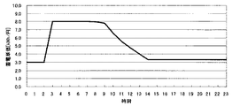
図15の(a)に機器3が稼動時刻情報に従って動作をしない場合の一例の1日の電力量の推移のグラフを、図15の(b)に機器3が稼動時刻情報に従って動作した場合の一例の1日の電力量の推移のグラフを示す。(a)では、機器3の稼動開始は、洗濯機は8:00、食器洗乾燥機は8:00と22:00、給湯機は3:00と18:00に稼動している。(b)では、洗濯機の稼動開始は10:00に、食器洗乾燥機の8:00稼動分は11:00に、給湯機の18:00分は15:00に稼動時刻を変更しており、グラフの比較からも明らかなように、太陽光発電装置1の余剰電力量は減少し、太陽光発電装置1の発電が終了した後に発生する電力を蓄電装置1で賄える量も増加している。
FIG. 15 (a) shows a graph of an example of the transition of daily power consumption when the
かかる構成によれば、太陽光発電装置1の電力料金単価を0として料金計算していることになり、最も太陽光発電装置1の発電量を最大とする機器3の稼動時刻の組み合わせを求めることが可能で、そこから求められる深夜の充電量を蓄電装置2に送信して、蓄電装置2の蓄電量を制御することによって、安価な深夜電力を過不足なく利用することができるため、省エネルギー性と経済性の双方を向上することができる。
According to this configuration, the unit price of the solar
本発明にかかる負荷制御装置は、太陽光発電装置1の発電量が最大となる機器3の稼動時刻の組み合わせとその際の深夜電力利用量を算出する稼動スケジュール・充電量算出部を有し、自然エネルギーの利用を最大とし、深夜電力による経済性を向上させるシステムとして有用である。また自然エネルギーを利用する風力発電等の利用効率の向上等の用途にも応用できる。
The load control device according to the present invention has an operation schedule / charge amount calculation unit that calculates a combination of operation times of the
1 太陽光発電装置
2 蓄電装置
3 機器
4 通信ネットワーク
5 発電履歴
6 発電予測部
7 負荷履歴
8 負荷予測部
9 稼動スケジュール・充電量算出部
10 余剰不足電力量算出部
11 充電量算出部
12 蓄電単価算出部
13 料金計算部
14 蓄電制御部
15 機器制御部
DESCRIPTION OF
Claims (5)
前記太陽光発電装置の発電した電力と、商用電源からの電力とを蓄える蓄電装置と、
電力を使用する少なくともひとつの機器と、
前記太陽光発電装置の発電量の予測値である予測発電量を算出する発電予測部と、
前記機器の電力量の予測値と、前記太陽光発電装置と前記商用電源と前記蓄電装置とが電力を供給する機器全て予測値とである予測負荷量を算出する負荷予測部と、
前記予測発電量と、前記予測負荷量と、前記蓄電装置内に残存している電力量である残存電力量とから、稼動時刻のスケジューリング情報である稼動スケジュールと、前記蓄電装置への前記商用電源からの充電量を算出する機器稼動スケジュール・充電量算出部と、
前記機器稼動スケジュール・充電量算出部から前記充電量を取得し、前記蓄電装置に充電指令を送信することによって、前記蓄電装置の前記充電量の制御を行う蓄電制御部と、
前記機器稼動スケジュール・充電量算出部から前記稼動スケジュールを取得し、前記機器に前記機器の起動の時刻情報である起動時刻情報を送信することによって、前記機器の制御を行う稼動機器制御部とを備えた負荷制御装置。 A solar power generation device that generates power by sunlight; and
A power storage device that stores electric power generated by the solar power generation device and electric power from a commercial power source;
At least one device that uses power,
A power generation prediction unit that calculates a predicted power generation amount that is a predicted value of the power generation amount of the solar power generation device;
A load prediction unit that calculates a predicted load amount that is a predicted value of the power amount of the device, and a predicted value of all the devices that the solar power generation device, the commercial power source, and the power storage device supply power;
From the predicted power generation amount, the predicted load amount, and the remaining power amount that is the amount of power remaining in the power storage device, an operation schedule that is scheduling information of operation time, and the commercial power source to the power storage device Device operation schedule / charge amount calculation unit to calculate the charge amount from
A power storage control unit that obtains the charge amount from the device operation schedule / charge amount calculation unit and transmits a charge command to the power storage device to control the charge amount of the power storage device;
An operation device control unit that controls the device by acquiring the operation schedule from the device operation schedule / charge amount calculation unit and transmitting activation time information that is activation time information of the device to the device. Load control device provided.
前記予測発電量と前記予測負荷量と前記残存電力量から、所定の昼間時間帯に発生し、前記予測負荷量を前記予測発電量が上回った場合の余りの電力である余剰電力量と、前記昼間時間帯に発生し、前記太陽光発電装置では賄えない電力である不足電力量とを算出する余剰不足電力量算出部と、
前記余剰電力量と、前記不足電力量と、前記残存電力量から、所定の夜間時間帯に前記蓄電装置に蓄電を行う電力量である充電量を算出する充電量算出部と、
前記充電量と、前記予測発電量と、前記残存電力量とから、0時間後から24時間後までの所定時間間隔毎の前記蓄電装置内の蓄電量と、前記蓄電装置内の電力量の単価である蓄電単価とを算出する蓄電単価算出部と、
前記蓄電量と前記蓄電単価と前記予測発電量と前記予測負荷量と前記残存電力量から、0時間後から24時間後までに発生する料金を算出する料金算出部とを備えた請求項1記載の負荷制御装置。 The device operation schedule / charge amount calculation unit
From the predicted power generation amount, the predicted load amount, and the remaining power amount, a surplus power amount that is generated when the predicted power generation amount exceeds the predicted load amount that occurs in a predetermined daytime period, and A surplus and deficient power amount calculating unit that calculates a deficient power amount that is generated during the daytime period and cannot be covered by the solar power generation device;
A charge amount calculation unit that calculates a charge amount that is an amount of power to be stored in the power storage device during a predetermined night time period from the surplus power amount, the insufficient power amount, and the remaining power amount;
From the charge amount, the predicted power generation amount, and the remaining power amount, the power storage amount in the power storage device at predetermined time intervals from 0 hours to 24 hours later, and the unit price of the power amount in the power storage device An electricity storage unit price calculating unit for calculating the electricity storage unit price,
The charge calculation part which calculates the charge generate | occur | produced from after 0 hour to 24 hours from the said electrical storage amount, the said electrical storage unit price, the said predicted electric power generation amount, the said predicted load amount, and the said remaining electric energy amount. Load control device.
Priority Applications (2)
| Application Number | Priority Date | Filing Date | Title |
|---|---|---|---|
| JP2006118883A JP2007295680A (en) | 2006-04-24 | 2006-04-24 | Load control device |
| JP2011022366A JP5278462B2 (en) | 2006-04-24 | 2011-02-04 | Load control device |
Applications Claiming Priority (1)
| Application Number | Priority Date | Filing Date | Title |
|---|---|---|---|
| JP2006118883A JP2007295680A (en) | 2006-04-24 | 2006-04-24 | Load control device |
Related Child Applications (1)
| Application Number | Title | Priority Date | Filing Date |
|---|---|---|---|
| JP2011022366A Division JP5278462B2 (en) | 2006-04-24 | 2011-02-04 | Load control device |
Publications (1)
| Publication Number | Publication Date |
|---|---|
| JP2007295680A true JP2007295680A (en) | 2007-11-08 |
Family
ID=38765759
Family Applications (2)
| Application Number | Title | Priority Date | Filing Date |
|---|---|---|---|
| JP2006118883A Pending JP2007295680A (en) | 2006-04-24 | 2006-04-24 | Load control device |
| JP2011022366A Expired - Fee Related JP5278462B2 (en) | 2006-04-24 | 2011-02-04 | Load control device |
Family Applications After (1)
| Application Number | Title | Priority Date | Filing Date |
|---|---|---|---|
| JP2011022366A Expired - Fee Related JP5278462B2 (en) | 2006-04-24 | 2011-02-04 | Load control device |
Country Status (1)
| Country | Link |
|---|---|
| JP (2) | JP2007295680A (en) |
Cited By (58)
| Publication number | Priority date | Publication date | Assignee | Title |
|---|---|---|---|---|
| JP2008043148A (en) * | 2006-08-09 | 2008-02-21 | Matsushita Electric Ind Co Ltd | Power supply system, control method of power supply system and program |
| JP2008043147A (en) * | 2006-08-09 | 2008-02-21 | Matsushita Electric Ind Co Ltd | Power supply system, control method of power supply system and program |
| JP2008289276A (en) * | 2007-05-17 | 2008-11-27 | Nippon Telegr & Teleph Corp <Ntt> | Apparatus controller, apparatus control system and apparatus control method |
| JP2010016989A (en) * | 2008-07-03 | 2010-01-21 | Sharp Corp | Electric power generating system |
| JP2010213507A (en) * | 2009-03-11 | 2010-09-24 | Chugoku Electric Power Co Inc:The | Natural energy integrated power storage system and natural energy integrated power storage method |
| WO2011036523A1 (en) * | 2009-09-28 | 2011-03-31 | パナソニック電工株式会社 | Grid-connected power supply system |
| WO2011042788A1 (en) * | 2009-10-05 | 2011-04-14 | パナソニック電工株式会社 | Electricity supply management device |
| JP2011114905A (en) * | 2009-11-25 | 2011-06-09 | Mitsubishi Electric Corp | Micro-grid system |
| JP2011120323A (en) * | 2009-11-30 | 2011-06-16 | Kyocera Corp | Control device, control system and control method |
| JP2011199953A (en) * | 2010-03-17 | 2011-10-06 | Toshiba Corp | Electrical energy management server and power stabilization system |
| JP2011229208A (en) * | 2010-04-15 | 2011-11-10 | Mitsubishi Electric Corp | Power management system and program |
| WO2011152512A1 (en) * | 2010-06-03 | 2011-12-08 | 三洋電機株式会社 | Power supply control device |
| JP2011254696A (en) * | 2010-06-01 | 2011-12-15 | Samsung Sdi Co Ltd | Power storage system and method for controlling the same |
| KR101102112B1 (en) * | 2009-12-04 | 2012-01-02 | 엘에스산전 주식회사 | Load control device and method of solar power system |
| JP2012100427A (en) * | 2010-11-01 | 2012-05-24 | Mitsubishi Electric Corp | Power management system, power management method and power management program |
| JP2012100420A (en) * | 2010-11-01 | 2012-05-24 | Mitsubishi Electric Corp | Energy management system and program |
| JP2012120295A (en) * | 2010-11-30 | 2012-06-21 | Mitsubishi Electric Corp | Residential electric energy management device, residential electric energy management system, residential electric energy management method, and program |
| DE102012202441A1 (en) | 2011-02-21 | 2012-08-23 | Denso Corporation | Power supply system for controlling quantity of electricity in battery in hybrid car, has load controlling device controlling amount of electric current such that excess of current is provided back or made to flow to power supply system |
| DE102012202465A1 (en) | 2011-02-21 | 2012-08-23 | Denso Corporation | Power supply system for supplying electric current to e.g. house to charge battery of hybrid car, has storage device storing surplus of electric solar when amount of electricity is larger than amount of electric current consumed by load |
| WO2012124370A1 (en) * | 2011-03-14 | 2012-09-20 | オムロン株式会社 | Load control device, control method therefor, and control program |
| JP2012191700A (en) * | 2011-03-09 | 2012-10-04 | Sumitomo Forestry Co Ltd | Storage battery utilization system |
| JP2012205430A (en) * | 2011-03-25 | 2012-10-22 | Toshiba Corp | Power management device, system, and method |
| JP2012222860A (en) * | 2011-04-04 | 2012-11-12 | Denso Corp | Power supply system |
| JP2012228141A (en) * | 2011-04-22 | 2012-11-15 | Toyota Motor Corp | House energy system |
| JP5138110B1 (en) * | 2012-05-24 | 2013-02-06 | キャリアシステム株式会社 | Solar power system |
| JPWO2011058761A1 (en) * | 2009-11-12 | 2013-03-28 | パナソニック株式会社 | Electric equipment power control device and telephone |
| WO2013047444A1 (en) * | 2011-09-28 | 2013-04-04 | 京セラ株式会社 | Power management system, power management device, and display control method |
| WO2013062016A1 (en) * | 2011-10-24 | 2013-05-02 | パナソニック株式会社 | Load controller, program, load control system |
| KR101280189B1 (en) * | 2011-10-17 | 2013-07-05 | 중앙대학교 산학협력단 | System and method for managing energy |
| JP2013176234A (en) * | 2012-02-27 | 2013-09-05 | Hitachi Ltd | Stand-alone power supply system |
| JP2013198207A (en) * | 2012-03-16 | 2013-09-30 | Mitsubishi Electric Corp | Facility controller and distributed power supply system |
| JP2013211952A (en) * | 2012-03-30 | 2013-10-10 | Mitsubishi Heavy Ind Ltd | Power management device, power management method and program |
| JP2013539340A (en) * | 2010-09-06 | 2013-10-17 | ソニー ヨーロッパ リミテッド | Power control apparatus and power control method |
| JP2013219848A (en) * | 2012-04-04 | 2013-10-24 | Denso Corp | Apparatus control system |
| JP2013258896A (en) * | 2012-06-13 | 2013-12-26 | Fujitsu Ltd | Smart grid electricity usage monitoring |
| WO2013190603A1 (en) * | 2012-06-18 | 2013-12-27 | 日立コンシューマエレクトロニクス株式会社 | Electric device control system |
| WO2014038327A1 (en) * | 2012-09-10 | 2014-03-13 | 株式会社日立製作所 | Consumer energy management device and system |
| JP2014512161A (en) * | 2011-04-08 | 2014-05-19 | エス・エム・アー・ゾラール・テヒノロギー・アクチエンゲゼルシャフト | Optimized load management |
| US8798830B2 (en) | 2010-02-15 | 2014-08-05 | Denso Corporation | Charge controller and navigation device for plug-in vehicle |
| JP2014217198A (en) * | 2013-04-26 | 2014-11-17 | 株式会社東芝 | Power storage amount management device and power storage amount management system |
| JP2015106968A (en) * | 2013-11-29 | 2015-06-08 | 三菱電機株式会社 | Charge/discharge controller, charge/discharge control method, and program |
| EP2602902A4 (en) * | 2010-08-05 | 2015-08-26 | Panasonic Ip Man Co Ltd | Power supplying system |
| US9148018B2 (en) | 2010-03-24 | 2015-09-29 | Panasonic Intellectual Property Management Co., Ltd. | Power supply device, power storage device, and power control device |
| JP2016140184A (en) * | 2015-01-28 | 2016-08-04 | 三菱電機株式会社 | Control device, control system, control method and program |
| US9423849B2 (en) | 2011-01-31 | 2016-08-23 | Nec Corporation | Electric power management system and electric power management method |
| WO2016158027A1 (en) * | 2015-03-30 | 2016-10-06 | オムロン株式会社 | Management device, management system, control method for management device, and control program |
| JP2016208801A (en) * | 2015-04-28 | 2016-12-08 | 京セラ株式会社 | Power management device and power conversion device |
| JPWO2015072029A1 (en) * | 2013-11-18 | 2017-03-09 | 三菱電機株式会社 | Controller, energy management system, power equipment, energy management method, and program |
| JP2017060230A (en) * | 2015-09-15 | 2017-03-23 | 積水化学工業株式会社 | Power management system, power management method, and program |
| US9639074B2 (en) | 2011-06-17 | 2017-05-02 | Panasonic Intellectual Property Management Co., Ltd. | Power supply system |
| WO2017098654A1 (en) * | 2015-12-11 | 2017-06-15 | 三菱電機株式会社 | Control device, schedule determination method, and program |
| JP2017225341A (en) * | 2013-04-24 | 2017-12-21 | シャープ株式会社 | Control system and control method |
| CN108233422A (en) * | 2018-02-09 | 2018-06-29 | 大工(青岛)新能源材料技术研究院有限公司 | A kind of light storage micro-grid operational control method based on PREDICTIVE CONTROL |
| KR101956791B1 (en) * | 2018-11-29 | 2019-03-14 | 주식회사 주빅스 | Photovoltaic power generation controller for residential use considering electricity tariff progress |
| JP2019080413A (en) * | 2017-10-23 | 2019-05-23 | 三菱電機株式会社 | Power management device and power management method |
| CN110476312A (en) * | 2017-04-07 | 2019-11-19 | 宝马股份公司 | Method for coordinating the Power Exchange between multiple technology junior units and electrical transmission network |
| JP2020205692A (en) * | 2019-06-17 | 2020-12-24 | 大和ハウス工業株式会社 | Power demand prediction system |
| CN115642617A (en) * | 2022-08-05 | 2023-01-24 | 科大数字(上海)能源科技有限公司 | Scheduling method of photovoltaic energy storage system |
Families Citing this family (23)
| Publication number | Priority date | Publication date | Assignee | Title |
|---|---|---|---|---|
| DE102011103600B4 (en) * | 2011-05-30 | 2019-11-21 | Sew-Eurodrive Gmbh & Co Kg | Method for controlling a device, in particular plant or machine, for the optimal utilization of an energy source |
| JP5353957B2 (en) * | 2011-06-14 | 2013-11-27 | 株式会社デンソー | Power supply system |
| DE102011051074A1 (en) * | 2011-06-15 | 2012-12-20 | Rwe Effizienz Gmbh | Controlling the use of energy |
| WO2013002155A1 (en) * | 2011-06-27 | 2013-01-03 | 日本電気株式会社 | Action suggestion device, action suggestion system, action suggestion method, and program |
| JP5494633B2 (en) * | 2011-12-02 | 2014-05-21 | コニカミノルタ株式会社 | Electronic apparatus and image forming apparatus |
| US10354297B2 (en) | 2011-12-21 | 2019-07-16 | Panasonic Intellectual Property Management Co., Ltd. | Information processing apparatus, method for generating electric power price list, information processing system, and display device |
| JP5836164B2 (en) * | 2012-03-09 | 2015-12-24 | 三菱電機株式会社 | Solar power system |
| JP5813544B2 (en) * | 2012-03-22 | 2015-11-17 | 株式会社東芝 | ENERGY MANAGEMENT DEVICE, ITS MANAGEMENT METHOD, AND ENERGY MANAGEMENT PROGRAM |
| US9535474B2 (en) | 2012-03-22 | 2017-01-03 | Kabushiki Kaisha Toshiba | Renewable energy management using weighted load patterns |
| JP6178045B2 (en) | 2012-04-16 | 2017-08-09 | 株式会社東芝 | Energy management system, energy management method, program, and server device |
| JP5947675B2 (en) * | 2012-08-30 | 2016-07-06 | パナソニック株式会社 | Power control device and power supply system using the same |
| JP6042184B2 (en) | 2012-11-21 | 2016-12-14 | 株式会社東芝 | Energy management system, energy management method, program, server device, and local server |
| US9727929B2 (en) | 2012-11-21 | 2017-08-08 | Kabushiki Kaisha Toshiba | Energy management system, energy management method, program, server apparatus, and local server |
| JP6045945B2 (en) | 2013-03-05 | 2016-12-14 | 株式会社東芝 | Energy management system, energy management method, program, and server device |
| JP5996460B2 (en) | 2013-03-08 | 2016-09-21 | 株式会社東芝 | Energy management apparatus, energy management system, energy management method and program |
| JP5959072B2 (en) | 2014-09-29 | 2016-08-02 | インターナショナル・ビジネス・マシーンズ・コーポレーションInternational Business Machines Corporation | Method for displaying conversion candidates associated with input character string, electronic device and server computer thereof, program for electronic device and program for server computer |
| EP3258565B1 (en) | 2015-02-09 | 2020-03-25 | Mitsubishi Electric Corporation | Control device, control system, control method, and program |
| JP6410940B2 (en) * | 2015-07-10 | 2018-10-24 | 三菱電機株式会社 | Power control apparatus, power control method, and program |
| US10122205B2 (en) | 2015-12-21 | 2018-11-06 | Intel Corporation | Systems and methods for adaptive charge termination |
| CN109066655B (en) * | 2018-08-20 | 2021-12-07 | 国网浙江省电力有限公司宁波供电公司 | Power distribution network planning method considering wind power and load uncertainty |
| CL2019000938A1 (en) | 2019-04-08 | 2019-10-18 | Univ Adolfo Ibanez | Equipment, system and method to optimally manage energy in a network for home and industrial use. |
| KR102136195B1 (en) * | 2019-09-23 | 2020-07-21 | (주)아리네트웍스 | Prediction system and method for efficiently supplying power to a plurality of customers and selling the remaining power |
| CN110912197B (en) * | 2019-12-12 | 2021-05-04 | 佛山市思正能源技术有限公司 | Modularized household light storage system capable of automatically scheduling energy and control method |
Citations (4)
| Publication number | Priority date | Publication date | Assignee | Title |
|---|---|---|---|---|
| JPH0638384A (en) * | 1992-02-25 | 1994-02-10 | Roehm Properties Bv | Energy control device |
| JP2002369383A (en) * | 2001-06-06 | 2002-12-20 | Hitachi Ltd | Home electric appliances control device |
| JP2004246685A (en) * | 2003-02-14 | 2004-09-02 | Osaka Gas Co Ltd | Green power supply system |
| JP2005253202A (en) * | 2004-03-04 | 2005-09-15 | Matsushita Electric Ind Co Ltd | Power control system, power control method, program, and recording medium |
Family Cites Families (2)
| Publication number | Priority date | Publication date | Assignee | Title |
|---|---|---|---|---|
| JP2003032890A (en) * | 2001-07-19 | 2003-01-31 | Senaa Kk | Load power controller |
| JP4229865B2 (en) * | 2004-03-30 | 2009-02-25 | 大阪瓦斯株式会社 | Energy supply system |
-
2006
- 2006-04-24 JP JP2006118883A patent/JP2007295680A/en active Pending
-
2011
- 2011-02-04 JP JP2011022366A patent/JP5278462B2/en not_active Expired - Fee Related
Patent Citations (4)
| Publication number | Priority date | Publication date | Assignee | Title |
|---|---|---|---|---|
| JPH0638384A (en) * | 1992-02-25 | 1994-02-10 | Roehm Properties Bv | Energy control device |
| JP2002369383A (en) * | 2001-06-06 | 2002-12-20 | Hitachi Ltd | Home electric appliances control device |
| JP2004246685A (en) * | 2003-02-14 | 2004-09-02 | Osaka Gas Co Ltd | Green power supply system |
| JP2005253202A (en) * | 2004-03-04 | 2005-09-15 | Matsushita Electric Ind Co Ltd | Power control system, power control method, program, and recording medium |
Cited By (82)
| Publication number | Priority date | Publication date | Assignee | Title |
|---|---|---|---|---|
| JP2008043148A (en) * | 2006-08-09 | 2008-02-21 | Matsushita Electric Ind Co Ltd | Power supply system, control method of power supply system and program |
| JP2008043147A (en) * | 2006-08-09 | 2008-02-21 | Matsushita Electric Ind Co Ltd | Power supply system, control method of power supply system and program |
| JP2008289276A (en) * | 2007-05-17 | 2008-11-27 | Nippon Telegr & Teleph Corp <Ntt> | Apparatus controller, apparatus control system and apparatus control method |
| JP2010016989A (en) * | 2008-07-03 | 2010-01-21 | Sharp Corp | Electric power generating system |
| JP2010213507A (en) * | 2009-03-11 | 2010-09-24 | Chugoku Electric Power Co Inc:The | Natural energy integrated power storage system and natural energy integrated power storage method |
| US9520623B2 (en) | 2009-09-28 | 2016-12-13 | Panasonic Intellectual Property Management Co., Ltd. | Grid-connected power supply system |
| JP2011072166A (en) * | 2009-09-28 | 2011-04-07 | Panasonic Electric Works Co Ltd | Interconnected power supply system |
| WO2011036523A1 (en) * | 2009-09-28 | 2011-03-31 | パナソニック電工株式会社 | Grid-connected power supply system |
| WO2011042788A1 (en) * | 2009-10-05 | 2011-04-14 | パナソニック電工株式会社 | Electricity supply management device |
| JP2011082277A (en) * | 2009-10-05 | 2011-04-21 | Panasonic Electric Works Co Ltd | Power supply management device |
| US9620990B2 (en) | 2009-10-05 | 2017-04-11 | Panasonic Intellectual Property Management Co., Ltd. | Electricity supply management device |
| JPWO2011058761A1 (en) * | 2009-11-12 | 2013-03-28 | パナソニック株式会社 | Electric equipment power control device and telephone |
| JP2011114905A (en) * | 2009-11-25 | 2011-06-09 | Mitsubishi Electric Corp | Micro-grid system |
| JP2011120323A (en) * | 2009-11-30 | 2011-06-16 | Kyocera Corp | Control device, control system and control method |
| KR101102112B1 (en) * | 2009-12-04 | 2012-01-02 | 엘에스산전 주식회사 | Load control device and method of solar power system |
| US8798830B2 (en) | 2010-02-15 | 2014-08-05 | Denso Corporation | Charge controller and navigation device for plug-in vehicle |
| JP2011199953A (en) * | 2010-03-17 | 2011-10-06 | Toshiba Corp | Electrical energy management server and power stabilization system |
| US9148018B2 (en) | 2010-03-24 | 2015-09-29 | Panasonic Intellectual Property Management Co., Ltd. | Power supply device, power storage device, and power control device |
| JP2011229208A (en) * | 2010-04-15 | 2011-11-10 | Mitsubishi Electric Corp | Power management system and program |
| JP2011254696A (en) * | 2010-06-01 | 2011-12-15 | Samsung Sdi Co Ltd | Power storage system and method for controlling the same |
| EP2400621A3 (en) * | 2010-06-01 | 2014-11-26 | Samsung SDI Co., Ltd. | Energy storage system and method of controlling the same |
| US8941263B2 (en) | 2010-06-01 | 2015-01-27 | Samsung Sdi Co., Ltd. | Energy storage system and method of controlling the same |
| WO2011152512A1 (en) * | 2010-06-03 | 2011-12-08 | 三洋電機株式会社 | Power supply control device |
| EP2602902A4 (en) * | 2010-08-05 | 2015-08-26 | Panasonic Ip Man Co Ltd | Power supplying system |
| JP2013539340A (en) * | 2010-09-06 | 2013-10-17 | ソニー ヨーロッパ リミテッド | Power control apparatus and power control method |
| JP2012100427A (en) * | 2010-11-01 | 2012-05-24 | Mitsubishi Electric Corp | Power management system, power management method and power management program |
| JP2012100420A (en) * | 2010-11-01 | 2012-05-24 | Mitsubishi Electric Corp | Energy management system and program |
| JP2012120295A (en) * | 2010-11-30 | 2012-06-21 | Mitsubishi Electric Corp | Residential electric energy management device, residential electric energy management system, residential electric energy management method, and program |
| US9423849B2 (en) | 2011-01-31 | 2016-08-23 | Nec Corporation | Electric power management system and electric power management method |
| US10270257B2 (en) | 2011-01-31 | 2019-04-23 | Nec Corporation | Electric power management system and electric power management method |
| JP2012175792A (en) * | 2011-02-21 | 2012-09-10 | Denso Corp | Electric power supply system |
| DE102012202465A1 (en) | 2011-02-21 | 2012-08-23 | Denso Corporation | Power supply system for supplying electric current to e.g. house to charge battery of hybrid car, has storage device storing surplus of electric solar when amount of electricity is larger than amount of electric current consumed by load |
| DE102012202441A1 (en) | 2011-02-21 | 2012-08-23 | Denso Corporation | Power supply system for controlling quantity of electricity in battery in hybrid car, has load controlling device controlling amount of electric current such that excess of current is provided back or made to flow to power supply system |
| JP2012175791A (en) * | 2011-02-21 | 2012-09-10 | Denso Corp | Electric power supply system |
| US8509957B2 (en) | 2011-02-21 | 2013-08-13 | Denso Corporation | Power supply system |
| JP2012191700A (en) * | 2011-03-09 | 2012-10-04 | Sumitomo Forestry Co Ltd | Storage battery utilization system |
| WO2012124370A1 (en) * | 2011-03-14 | 2012-09-20 | オムロン株式会社 | Load control device, control method therefor, and control program |
| US9252597B2 (en) | 2011-03-25 | 2016-02-02 | Kabushiki Kaisha Toshiba | Electric power management apparatus, system and method |
| JP2012205430A (en) * | 2011-03-25 | 2012-10-22 | Toshiba Corp | Power management device, system, and method |
| JP2012222860A (en) * | 2011-04-04 | 2012-11-12 | Denso Corp | Power supply system |
| US9760956B2 (en) | 2011-04-08 | 2017-09-12 | Sma Solar Technology Ag | Optimized load management |
| JP2014512161A (en) * | 2011-04-08 | 2014-05-19 | エス・エム・アー・ゾラール・テヒノロギー・アクチエンゲゼルシャフト | Optimized load management |
| JP2012228141A (en) * | 2011-04-22 | 2012-11-15 | Toyota Motor Corp | House energy system |
| US9639074B2 (en) | 2011-06-17 | 2017-05-02 | Panasonic Intellectual Property Management Co., Ltd. | Power supply system |
| US9547349B2 (en) | 2011-09-28 | 2017-01-17 | Kyocera Corporation | Power management system, power management apparatus, and display control method |
| WO2013047444A1 (en) * | 2011-09-28 | 2013-04-04 | 京セラ株式会社 | Power management system, power management device, and display control method |
| JPWO2013047444A1 (en) * | 2011-09-28 | 2015-03-26 | 京セラ株式会社 | Power management system, power management apparatus, and display control method |
| KR101280189B1 (en) * | 2011-10-17 | 2013-07-05 | 중앙대학교 산학협력단 | System and method for managing energy |
| US10116142B2 (en) | 2011-10-24 | 2018-10-30 | Panasonic Intellectual Property Management Co., Ltd. | Load control apparatus, program, method, and system |
| WO2013062016A1 (en) * | 2011-10-24 | 2013-05-02 | パナソニック株式会社 | Load controller, program, load control system |
| JP2013110951A (en) * | 2011-10-24 | 2013-06-06 | Panasonic Corp | Load controller, program and load control system |
| EP2773008A4 (en) * | 2011-10-24 | 2015-07-15 | Panasonic Ip Man Co Ltd | LOAD REGULATOR, PROGRAM, AND LOAD REGULATION SYSTEM |
| JP2013176234A (en) * | 2012-02-27 | 2013-09-05 | Hitachi Ltd | Stand-alone power supply system |
| JP2013198207A (en) * | 2012-03-16 | 2013-09-30 | Mitsubishi Electric Corp | Facility controller and distributed power supply system |
| JP2013211952A (en) * | 2012-03-30 | 2013-10-10 | Mitsubishi Heavy Ind Ltd | Power management device, power management method and program |
| JP2013219848A (en) * | 2012-04-04 | 2013-10-24 | Denso Corp | Apparatus control system |
| JP5138110B1 (en) * | 2012-05-24 | 2013-02-06 | キャリアシステム株式会社 | Solar power system |
| JP2013258896A (en) * | 2012-06-13 | 2013-12-26 | Fujitsu Ltd | Smart grid electricity usage monitoring |
| JPWO2013190603A1 (en) * | 2012-06-18 | 2016-02-08 | 日立アプライアンス株式会社 | Electrical equipment control system |
| WO2013190603A1 (en) * | 2012-06-18 | 2013-12-27 | 日立コンシューマエレクトロニクス株式会社 | Electric device control system |
| JP2014054123A (en) * | 2012-09-10 | 2014-03-20 | Hitachi Ltd | Customer energy management apparatus and system |
| WO2014038327A1 (en) * | 2012-09-10 | 2014-03-13 | 株式会社日立製作所 | Consumer energy management device and system |
| JP2017225341A (en) * | 2013-04-24 | 2017-12-21 | シャープ株式会社 | Control system and control method |
| JP2014217198A (en) * | 2013-04-26 | 2014-11-17 | 株式会社東芝 | Power storage amount management device and power storage amount management system |
| JPWO2015072029A1 (en) * | 2013-11-18 | 2017-03-09 | 三菱電機株式会社 | Controller, energy management system, power equipment, energy management method, and program |
| JP2015106968A (en) * | 2013-11-29 | 2015-06-08 | 三菱電機株式会社 | Charge/discharge controller, charge/discharge control method, and program |
| JP2016140184A (en) * | 2015-01-28 | 2016-08-04 | 三菱電機株式会社 | Control device, control system, control method and program |
| WO2016158027A1 (en) * | 2015-03-30 | 2016-10-06 | オムロン株式会社 | Management device, management system, control method for management device, and control program |
| US10333305B2 (en) | 2015-03-30 | 2019-06-25 | Omron Corporation | Management device, management system, control method for management device, and control program |
| JP2016208801A (en) * | 2015-04-28 | 2016-12-08 | 京セラ株式会社 | Power management device and power conversion device |
| JP2017060230A (en) * | 2015-09-15 | 2017-03-23 | 積水化学工業株式会社 | Power management system, power management method, and program |
| JPWO2017098654A1 (en) * | 2015-12-11 | 2018-04-12 | 三菱電機株式会社 | Control device, schedule determination method and program |
| WO2017098654A1 (en) * | 2015-12-11 | 2017-06-15 | 三菱電機株式会社 | Control device, schedule determination method, and program |
| CN110476312A (en) * | 2017-04-07 | 2019-11-19 | 宝马股份公司 | Method for coordinating the Power Exchange between multiple technology junior units and electrical transmission network |
| JP2019080413A (en) * | 2017-10-23 | 2019-05-23 | 三菱電機株式会社 | Power management device and power management method |
| CN108233422A (en) * | 2018-02-09 | 2018-06-29 | 大工(青岛)新能源材料技术研究院有限公司 | A kind of light storage micro-grid operational control method based on PREDICTIVE CONTROL |
| CN108233422B (en) * | 2018-02-09 | 2021-07-02 | 大工(青岛)新能源材料技术研究院有限公司 | Light storage micro-grid operation control method based on predictive control |
| KR101956791B1 (en) * | 2018-11-29 | 2019-03-14 | 주식회사 주빅스 | Photovoltaic power generation controller for residential use considering electricity tariff progress |
| JP2020205692A (en) * | 2019-06-17 | 2020-12-24 | 大和ハウス工業株式会社 | Power demand prediction system |
| JP7286428B2 (en) | 2019-06-17 | 2023-06-05 | 大和ハウス工業株式会社 | Power demand forecast system |
| CN115642617A (en) * | 2022-08-05 | 2023-01-24 | 科大数字(上海)能源科技有限公司 | Scheduling method of photovoltaic energy storage system |
| CN115642617B (en) * | 2022-08-05 | 2023-06-09 | 科大数字(上海)能源科技有限公司 | Scheduling method of photovoltaic energy storage system |
Also Published As
| Publication number | Publication date |
|---|---|
| JP5278462B2 (en) | 2013-09-04 |
| JP2011092002A (en) | 2011-05-06 |
Similar Documents
| Publication | Publication Date | Title |
|---|---|---|
| JP5278462B2 (en) | Load control device | |
| Shakeri et al. | Implementation of a novel home energy management system (HEMS) architecture with solar photovoltaic system as supplementary source | |
| Merabet et al. | Energy management system for optimal cost and storage utilization of renewable hybrid energy microgrid | |
| US9489701B2 (en) | Adaptive energy management system | |
| US11971185B2 (en) | Method for improving the performance of the energy management in a nearly zero energy building | |
| US9261284B2 (en) | Operation planning method, and heat pump hot water supply and heating system operation method | |
| TWI441407B (en) | Method and apparatus for allocating electrical energy and computer-readable | |
| JP6592454B2 (en) | Power control system, power control method and program | |
| JPWO2017217466A1 (en) | Power management system | |
| CN105680471A (en) | Apparatus for the conversion and optimized consumption management of power from renewable sources | |
| Sherif et al. | An optimization framework for home demand side management incorporating electric vehicles | |
| JP5948217B2 (en) | Fuel cell operation control method and operation control system in an apartment house | |
| FI128279B (en) | A method and a system for dynamic aggregation of a fleet of power units to provide frequency regulation of a power system | |
| Syed et al. | Energy advancement integrated predictive optimization of photovoltaic assisted battery energy storage system for cost optimization | |
| Vilar et al. | Residential energy management system with photovoltaic generation using simulated annealing | |
| CN116316654A (en) | Intelligent household electrical appliance power consumption flexible load optimal scheduling method and system | |
| KR20220008565A (en) | HEMS optimization method and apparatus using hierarchical deep reinforcement learning | |
| Singabhattu et al. | Distributed energy resources optimization for demand response using MILP | |
| Ben Belgacem et al. | Design and Implementation of Multi-Source and Multi-Consumer Energy Sharing System in Collaborative Smart Microgrid Installation | |
| JP2007104775A (en) | Energy demanding/supplying method in combined power supply, and energy demanding/supplying apparatus | |
| JP7469014B2 (en) | Power interchange system | |
| Gheouany et al. | Optimal supply-side and demand-side management strategies for energy efficiency in residential buildings using particle swarm optimization | |
| Martins et al. | LP-based predictive energy management system for residential PV/BESS | |
| Azad et al. | A low complexity residential demand response strategy using binary particle swarm optimization | |
| Mindra et al. | Combined peak shaving/time shifting strategy for microgrid controlled renewable energy efficiency optimization |
Legal Events
| Date | Code | Title | Description |
|---|---|---|---|
| A621 | Written request for application examination |
Free format text: JAPANESE INTERMEDIATE CODE: A621 Effective date: 20090223 |
|
| RD01 | Notification of change of attorney |
Free format text: JAPANESE INTERMEDIATE CODE: A7421 Effective date: 20091127 |
|
| A977 | Report on retrieval |
Free format text: JAPANESE INTERMEDIATE CODE: A971007 Effective date: 20101101 |
|
| A131 | Notification of reasons for refusal |
Free format text: JAPANESE INTERMEDIATE CODE: A131 Effective date: 20101207 |
|
| A521 | Written amendment |
Free format text: JAPANESE INTERMEDIATE CODE: A523 Effective date: 20110204 |
|
| A131 | Notification of reasons for refusal |
Free format text: JAPANESE INTERMEDIATE CODE: A131 Effective date: 20111122 |
|
| A02 | Decision of refusal |
Free format text: JAPANESE INTERMEDIATE CODE: A02 Effective date: 20120911 |