[go: up one dir, main page]

JP2007115377A - Disk unit - Google Patents

Disk unit Download PDF

Info

Publication number
JP2007115377A
JP2007115377A JP2005308603A JP2005308603A JP2007115377A JP 2007115377 A JP2007115377 A JP 2007115377A JP 2005308603 A JP2005308603 A JP 2005308603A JP 2005308603 A JP2005308603 A JP 2005308603A JP 2007115377 A JP2007115377 A JP 2007115377A
Authority
JP
Japan
Prior art keywords
disk
loading
frame member
state
pin
Prior art date
Legal status (The legal status is an assumption and is not a legal conclusion. Google has not performed a legal analysis and makes no representation as to the accuracy of the status listed.)
Pending
Application number
JP2005308603A
Other languages
Japanese (ja)
Inventor
So Matsumoto
創 松本
Current Assignee (The listed assignees may be inaccurate. Google has not performed a legal analysis and makes no representation or warranty as to the accuracy of the list.)
Teac Corp
Original Assignee
Teac Corp
Priority date (The priority date is an assumption and is not a legal conclusion. Google has not performed a legal analysis and makes no representation as to the accuracy of the date listed.)
Filing date
Publication date
Application filed by Teac Corp filed Critical Teac Corp
Priority to JP2005308603A priority Critical patent/JP2007115377A/en
Publication of JP2007115377A publication Critical patent/JP2007115377A/en
Pending legal-status Critical Current

Links

Images

Landscapes

  • Holding Or Fastening Of Disk On Rotational Shaft (AREA)
  • Feeding And Guiding Record Carriers (AREA)

Abstract

【課題】ディスク装置のローディングモータによるクランプヘッドの複数回の上下動によりディスクをクランプするにあたり、ローディングモータの損傷を防止し、耐久性を向上する。
【解決手段】フレーム部材を上下動させることによりクランプヘッドによりディスクの中心孔のクランプまたはクランプの解除が可能となるようにし、且つ、ディスクを本体内外へローディングまたはアンローディングさせるため、該ディスクを前記フレーム部材上で支持しつつ水平方向に前進後退させる複数のアームと前記フレーム部材を上下動させる駆動機構を備え、該フレーム部材を複数回上下動させてディスクの中心孔をクランプするようにしたディスク装置において、前記フレーム部材の駆動機構の駆動源となるローディングモータに供給される電圧の方向が反転する遷移時に、電圧の供給が停止される微少期間が介在するようにする。
【選択図】図39
When a disk is clamped by a plurality of vertical movements of a clamp head by a loading motor of the disk device, the loading motor is prevented from being damaged and durability is improved.
In order to enable the clamp head to clamp or release the center hole of the disk by moving the frame member up and down, and to load or unload the disk into or out of the main body, the disk is A disc having a plurality of arms that are supported on the frame member and moved forward and backward in the horizontal direction and a drive mechanism that moves the frame member up and down, and that the frame member is moved up and down a plurality of times to clamp the center hole of the disc. In the apparatus, at the time of transition in which the direction of the voltage supplied to the loading motor serving as the drive source of the drive mechanism of the frame member is reversed, a minute period in which the supply of voltage is stopped is interposed.
[Selection] Figure 39

Description

本発明は、各種コンピュータシステムなどの情報機器において、大量の情報を記録する記録媒体としての光学的に記録再生されるディスク(例えば、CD−R/RW、DVD−R/−R/RW/RAM/+Rなど)をドライブするディスク装置に関する。   The present invention relates to a disc (for example, CD-R / RW, DVD-R / -R / RW / RAM) that is optically recorded / reproduced as a recording medium for recording a large amount of information in information equipment such as various computer systems. / + R, etc.).

一般にパーソナルコンピュータ(以下、パソコンという)などに内蔵されているディスク装置は、通常、ディスクを装填するディスクトレイを備えており、このディスクトレイが前進後退するように構成されている。そして、ディスクトレイに装填されたディスクは、ディスク装置の本体内でドライブされ、情報の記録または再生が行われる。   Generally, a disk device built in a personal computer (hereinafter referred to as a personal computer) or the like is usually provided with a disk tray for loading a disk, and the disk tray is configured to move forward and backward. Then, the disk loaded in the disk tray is driven in the main body of the disk device, and information is recorded or reproduced.

一方、ディスクトレイを用いない方式として、いわゆるスロットイン方式のディスク装置も多く採用される傾向にあり、パソコンの薄型化、小型化に好適なものとなっている。このスロットイン方式のディスク装置は、装置本体へのディスクのロード(搬入)/アンロード(搬出)にディスクトレイを用いないため、操作者が装置前面のベゼルのスロットからディスクの過半をスロットに差し込むと、以後、装置本体のローディング機構が作動して自動的にロードされるようにしている。   On the other hand, as a system that does not use a disk tray, so-called slot-in type disk devices tend to be often employed, which is suitable for making a personal computer thinner and smaller. In this slot-in type disk device, the disk tray is not used for loading (unloading) / unloading (unloading) the disk into the device body, so the operator inserts the majority of the disk into the slot from the slot of the bezel on the front of the device Thereafter, the loading mechanism of the apparatus main body operates to automatically load.

図41ならびに図42は、従来のスロットイン方式のディスク装置におけるローディング機構における構成および動作態様を示すものである。同図に示す構成においては、ディスクDを操作者が挿入すると、ディスクDは第1の揺動体100の先端のピン100aおよび左右のガイド体101・102、そして途中から第2の揺動体103の先端のピン103aにより高さ方向と左右位置を規制されながら図41に示す位置まで到達する。   41 and 42 show the configuration and operation of the loading mechanism in the conventional slot-in type disk apparatus. In the configuration shown in the figure, when the operator inserts the disc D, the disc D is inserted into the pin 100a at the front end of the first oscillating body 100, the left and right guide bodies 101 and 102, and the second oscillating body 103 from the middle. The position reaches the position shown in FIG. 41 while the height direction and the left-right position are restricted by the pin 103a at the tip.

このとき、第1の揺動体100はディスクDにより先端のピン100aが押されて矢印100A方向に回転し、また、第2の揺動体103もディスクDにより先端のピン103aが押されて矢印103A方向に回転する。そして、スイッチレバー104が第2の揺動体103の端部に押されて矢印104A方向に回転し、検出スイッチ5を作動する。   At this time, the first rocking body 100 is rotated in the direction of arrow 100A by pushing the tip pin 100a by the disk D, and the second rocking body 103 is also pushed by the disk D by the tip pin 103a being pushed by the arrow 103A. Rotate in the direction. Then, the switch lever 104 is pushed by the end of the second oscillating body 103 and rotates in the direction of the arrow 104A, and the detection switch 5 is operated.

前記検出スイッチ105が作動すると駆動手段106が始動し、第1のスライド部材107の矢印107A方向への移動が開始される。この第1のスライド部材107と第2のスライド部材108は、各先端がスライド連結部材109で連結され、このスライド連結部材109がピン110で揺動可能に枢支されているので、第1のスライド部材107の後退に同期して第2のスライド部材108が矢印108A方向に前進する。   When the detection switch 105 is activated, the driving means 106 is started, and the movement of the first slide member 107 in the direction of the arrow 107A is started. The first slide member 107 and the second slide member 108 are connected at their respective ends by a slide connecting member 109, and the slide connecting member 109 is pivotally supported by a pin 110 so that the first slide member 107 and the second slide member 108 are pivoted. In synchronization with the retraction of the slide member 107, the second slide member 108 advances in the direction of the arrow 108A.

このようにして、第1のスライド部材107が後退を開始すると、第1の揺動体100は矢印100B方向に回転し、これにより第1の揺動体100の先端のピン100aがディスクDをディスク位置決め部材111のピン111a・111bに当接するまで矢印107A方向へ搬送する。   In this way, when the first slide member 107 starts to move backward, the first oscillating body 100 rotates in the direction of the arrow 100B, whereby the pin 100a at the tip of the first oscillating body 100 positions the disk D in the disk positioning. It is conveyed in the direction of the arrow 107A until it comes into contact with the pins 111a and 111b of the member 111.

このとき、第2の揺動体103のピン103aは矢印103A方向に回転するので、第2の揺動体103のピン103aは、第1の揺動体100の先端のピン100aと同期してディスクDを支持したまま矢印103A方向に移動し、ディスクDがディスク位置決め部材111のピン111a・111bに当接した後は、ディスクDから僅かに離れた位置まで回転する。   At this time, since the pin 103a of the second rocking body 103 rotates in the direction of the arrow 103A, the pin 103a of the second rocking body 103 is synchronized with the pin 100a at the tip of the first rocking body 100 and the disk D is rotated. After moving in the direction of the arrow 103A while being supported and the disk D abuts on the pins 111a and 111b of the disk positioning member 111, the disk D rotates to a position slightly away from the disk D.

以上は装置内部へディスクDを搬入する場合のローディング機構の動作態様であるが、ディスクDを装置外部へ搬出する場合のローディング機構は、前述と逆の動作態様となる。即ち、ディスクDが装置内部で定位置にあるとき、アンロードの指示にもとづき、駆動手段106が逆転方向に始動されると、第1のスライド部材107が矢印107B方向に前進を開始し、スライド連結部材109に連結されている第2のスライド部材108が同期して矢印108B方向に後退を開始する。これにより、第1の揺動体100は矢印100A方向に、そして第2の揺動体103は矢印103B方向に回転するので、各々の先端のピン100a・103aによりディスクDが支持されて装置外部に搬出されることになる。   The above is the operation mode of the loading mechanism when the disk D is carried into the apparatus, but the loading mechanism when the disk D is carried out of the apparatus is the operation mode opposite to that described above. That is, when the disk D is in a fixed position inside the apparatus, when the driving means 106 is started in the reverse direction based on the unload instruction, the first slide member 107 starts to advance in the direction of the arrow 107B, and the slide The second slide member 108 connected to the connection member 109 starts to retract in the direction of the arrow 108B in synchronization. As a result, the first rocking body 100 rotates in the direction of the arrow 100A and the second rocking body 103 rotates in the direction of the arrow 103B, so that the disk D is supported by the pins 100a and 103a at the respective leading ends and carried out of the apparatus. Will be.

なお、装置内部へ搬入されたディスクDは、定位置で上下動するクランプヘッド112にクランプされるようにしてある。このクランプヘッド112は、スピンドルモータ114の駆動軸に固定されたターンテーブル113と一体化されており、さらに前記スピンドルモータ114は、フレーム部材115に配設され、このフレーム部材115を昇降機構により上下動するようにしている(例えば、特許文献1)。   The disk D carried into the apparatus is clamped by a clamp head 112 that moves up and down at a fixed position. The clamp head 112 is integrated with a turntable 113 fixed to a drive shaft of the spindle motor 114. The spindle motor 114 is disposed on a frame member 115, and the frame member 115 is moved up and down by an elevating mechanism. It is made to move (for example, patent document 1).

このようにクランプヘッド112を上下動してディスクDの中心孔Daをクランプする方式において、そのクランプが確実に実行されず、ディスクをドライブできなくなる不具合が発生する場合がある。かかる不具合は、ディスクDの中心孔Daに図43(A)に示すような段部d1、図43(B)に示すような溝d2が形成されたディスク、あるいは記録層が多層である場合、図43(C)に示すように、その中間層による溝d3が形成されたディスクに多く発生する。そこで、このようなディスクであっても、そのクランプの成功率を向上するため、クランプヘッドを複数回上下動することが既に実施されている(例えば、特許文献2)。
特開2002−117604号公報 特開2005−85449号公報
As described above, in the system in which the clamp head 112 is moved up and down to clamp the center hole Da of the disk D, there is a case where the clamping is not reliably performed and the disk cannot be driven. Such inconvenience occurs when the disk D has a step d1 as shown in FIG. 43 (A) and a groove d2 as shown in FIG. 43 (B) in the center hole Da of the disk D, or when the recording layer is multi-layered. As shown in FIG. 43 (C), it frequently occurs in the disk in which the groove d3 is formed by the intermediate layer. Therefore, even in such a disk, in order to improve the success rate of the clamp, the clamp head has been moved up and down a plurality of times (for example, Patent Document 2).
JP 2002-117604 A JP 2005-85449 A

前述したように、クランプヘッドの上下動を複数回にした場合、クランプの不成功の確率を大きく低下することができる。かかる動作は、クランプヘッドを上下動する駆動機構を、ディスクのクランプ位置の僅かな範囲で繰り返し動作を行うのであるが、これは、駆動機構の動力源となるモータの正転と逆転を繰り返すことにより行われている。   As described above, when the vertical movement of the clamp head is performed a plurality of times, the probability of unsuccessful clamping can be greatly reduced. In this operation, the drive mechanism that moves the clamp head up and down is repeatedly operated within a small range of the disk clamp position. This is because the motor that is the power source of the drive mechanism repeats normal rotation and reverse rotation. It is done by.

図44は、このように駆動機構を動作制御するため、モータに供給される電圧の状態を示すものである。同図に示すように、スロットから挿入されたディスクDを検知するとローディングモータに自動ローディングのための正電圧(+V)の供給が開始され(t1)、ローディングモータが駆動される。これに伴ってディスクDが本体内へローディングされ、このディスクDがクランプヘッド上に達すると、該クランプヘッドが上下動して中心孔Daに対する第1回のクランプ動作が行われる(t2〜t4)。   FIG. 44 shows the state of the voltage supplied to the motor in order to control the operation of the drive mechanism in this way. As shown in the figure, when the disk D inserted from the slot is detected, supply of a positive voltage (+ V) for automatic loading to the loading motor is started (t1), and the loading motor is driven. Accordingly, the disk D is loaded into the main body, and when the disk D reaches the clamp head, the clamp head moves up and down to perform the first clamping operation on the center hole Da (t2 to t4). .

この第1回のクランプ動作が終了すると、ディスクDがクランプされたか否かに拘わらず、第1回のクランプ動作の直後、ローディングモータに負電圧(−V)がクランプヘッドの上下動に必要な期間だけ供給される(t4〜t6)。これにより、駆動機構が逆転するため、クランプヘッドが再度上下動し、第2回のクランプ動作が行われる。そして、負電圧(−V)の供給が停止された時点(t6)に達すると同時に再度正電圧(+V)がクランプヘッドの上下動に必要な期間だけローディングモータに供給される(t6〜t8)。これにより、駆動機構が再度正転するので、クランプヘッドが第3回のクランプ動作を行い、ディスクDをクランプしたクランプヘッドが最終の定位置で静止する。   When the first clamping operation is completed, a negative voltage (-V) is required for the loading motor to move the clamp head up and down immediately after the first clamping operation regardless of whether or not the disk D is clamped. It is supplied only for a period (t4 to t6). As a result, the drive mechanism reverses, so that the clamp head moves up and down again, and the second clamping operation is performed. At the same time when the supply of the negative voltage (−V) is stopped (t6), the positive voltage (+ V) is supplied again to the loading motor for a period necessary for the vertical movement of the clamp head (t6 to t8). . As a result, the drive mechanism rotates forward again, so that the clamp head performs the third clamping operation, and the clamp head that clamps the disk D stops at the final fixed position.

このようにクランプ動作が数度に亘り実行されるようにするには、ローディングの最終段階で駆動機構の正転〜逆転〜正転が繰り返されるようにするため、ローディングモータに正電圧と負電圧を交互に供給するようにしている。そして、従来、このような方法においては、正電圧(+V)の供給の終了(t4)と同時に負電圧(−V)を供給するようにしており、また、この負電圧(−V)の供給の終了(t6)と同時に正電圧(+V)を供給することになる。これは、ローディングモータが慣性による正転方向または逆転方向への動作が終了していない状態において負電圧(−V)または正電圧(+V)が供給されることになるのであり、かかる状態が以下に述べるような不具合の要因となることが確認された。   In order to perform the clamping operation several times in this way, a positive voltage and a negative voltage are applied to the loading motor so that the forward rotation, reverse rotation, and normal rotation of the drive mechanism are repeated at the final stage of loading. Are alternately supplied. Conventionally, in such a method, the negative voltage (−V) is supplied simultaneously with the end of the supply of the positive voltage (+ V) (t4), and the supply of the negative voltage (−V) is also performed. The positive voltage (+ V) is supplied simultaneously with the end of (t6). This is because a negative voltage (−V) or a positive voltage (+ V) is supplied in a state where the loading motor has not finished moving in the forward direction or the reverse direction due to inertia. It has been confirmed that this causes the problems as described in (1).

即ち、正電圧(+V)または負電圧(−V)の供給が停止された直後のローディングモータは慣性によりロータの回転が継続されるため、これに捲かれたコイルに逆起電流が発生する。そして、これと同時に負電圧(−V)または正電圧(+V)の供給が開始されるため、これにより起動電流に前記逆起電流が重畳してローディングモータに許容される範囲を超えて増大した電流が流れることになる。図45は、かかる状態における電流の発生状態を示したもので、許容電流値が600mA程度であるローディングモータにおいて、起動電流に逆起電流が重畳して800mAという大きな電流が流れることを確認できた。   That is, since the rotor of the loading motor immediately after the supply of the positive voltage (+ V) or the negative voltage (−V) is stopped continues to rotate due to inertia, a counter electromotive current is generated in the coil wound by the loading motor. At the same time, supply of a negative voltage (−V) or a positive voltage (+ V) is started, so that the counter electromotive current is superimposed on the starting current and increases beyond the allowable range for the loading motor. Current will flow. FIG. 45 shows a current generation state in such a state, and in a loading motor having an allowable current value of about 600 mA, it was confirmed that a large current of 800 mA flows with a back electromotive current superimposed on the starting current. .

周知のように、本発明が対象とするディスク装置は、小型化、薄型化が重要な課題であり、大きな電流に対する耐久性を向上するため、ローディングモータを不必要に大型化することはできず、通常の動作態様で流れる電流を許容する範囲で設計され、小型化されたローディングモータが採用されている。したがって、このようなローディングモータに前述したような過大な電流が流れると、整流子などを破損し、耐久性を大きく低下してしまうことになる。なお、本願出願人による前記状態、即ち、許容範囲を超える電流が流れる状態における耐久試験においては、ローディングモータの繰り返し動作において、平均12,000回の試行で障害が発生することを確認できた。   As is well known, in the disk device targeted by the present invention, downsizing and thinning are important issues, and in order to improve durability against a large current, the loading motor cannot be unnecessarily enlarged. A compact loading motor designed in a range that allows a current to flow in a normal operation mode is employed. Therefore, when an excessive current as described above flows through such a loading motor, the commutator and the like are damaged, and the durability is greatly reduced. In the endurance test in the above-described state by the applicant of the present application, that is, a state in which a current exceeding the allowable range flows, it has been confirmed that a failure occurs in an average of 12,000 trials in the repeated operation of the loading motor.

そこで本発明は、以下に述べる手段により上記課題を解決するようにした。即ち、請求項1記載の発明では、クランプヘッドを備えたターンテーブルおよびスピンドルモータからなるディスクドライブ機構を設けたフレーム部材を上下動させることにより前記クランプヘッドによりディスクの中心孔のクランプまたはクランプの解除が可能となるようにし、且つ、ディスクを本体内へローディングまたは本体外へアンローディングさせるため、該ディスクを前記フレーム部材上で支持しつつ水平方向に前進後退させる複数のアームと前記フレーム部材を上下動させる駆動機構を備え、該フレーム部材を複数回上下動させてディスクの中心孔をクランプするようにしたディスク装置において、前記フレーム部材の駆動機構の駆動源となるローディングモータに供給される電圧の方向が反転する遷移時に、電圧の供給が停止される微少期間が介在するようにする。   Therefore, the present invention solves the above problems by the means described below. That is, according to the first aspect of the present invention, a frame member provided with a disk drive mechanism comprising a turntable having a clamp head and a spindle motor is moved up and down to clamp or release the center hole of the disk by the clamp head. In order to load the disk into the main body or to unload the disk from the main body, a plurality of arms that support the disk on the frame member and move forward and backward in the horizontal direction and the frame member are moved up and down. In a disk apparatus comprising a drive mechanism for moving the frame member and vertically moving the frame member a plurality of times to clamp the center hole of the disk, a voltage supplied to a loading motor serving as a drive source of the drive mechanism of the frame member During a transition that reverses direction, the supply of voltage stops. Minute period that is to so interposed.

本発明によれば、フレーム部材の駆動機構を反転駆動するにあたり、ローディングモータに供給される電圧の方向が反転する遷移時に、電圧の供給が停止される微少期間が介在するようにしたので、この微少期間にローディングモータのロータの慣性により発生する逆起電流の影響を回避することができ、これによりローディングモータの損傷を防止し、耐久性を向上することができる。   According to the present invention, when the driving mechanism of the frame member is driven in reverse, a minute period in which the supply of voltage is stopped is interposed at the time of transition in which the direction of the voltage supplied to the loading motor is reversed. It is possible to avoid the influence of the counter electromotive current generated due to the inertia of the rotor of the loading motor during a very short period, thereby preventing damage to the loading motor and improving durability.

以下、本発明の実施の形態を図にもとづいて詳細に説明する。なお、本発明の理解を容易とするため、全体の構成の概要を含め説明する。   Hereinafter, embodiments of the present invention will be described in detail with reference to the drawings. In order to facilitate understanding of the present invention, a description will be given including an overview of the overall configuration.

図1は、本発明を実施したスロットイン方式のディスク装置1の外観を示す図であり、シールド状態に構成されたシャーシケース2の天板の中央に開口2aが形成されており、さらにこの開口2aの開口周縁部に内部へ突出する凸部2bが形成されている。前記凸部2bにはこれに連続する前端へ向かう上り勾配(背面では下り勾配)の第1の傾斜面2cが形成されており、また、後述するディスク支持アームの上下動を案内する第2の傾斜面2dが形成されている。   FIG. 1 is a view showing the appearance of a slot-in type disk device 1 embodying the present invention. An opening 2a is formed at the center of a top plate of a chassis case 2 configured in a shield state. A convex portion 2b is formed on the peripheral edge of the opening 2a. The convex portion 2b is formed with a first inclined surface 2c having an upward gradient (downward gradient on the back surface) toward the front end which is continuous with the convex portion 2b. An inclined surface 2d is formed.

そして、シャーシケース2の前端にはベゼル3が固定されており、このベゼル3には、ディスクDを挿入するスロット3aとエマージェンシー解除のための通孔3b・3cが形成されている。また、ベゼル3には、収容されているディスクDの装置外部への搬出を指示するための押釦4およびディスク装置1の動作状態を表示するためのインジケータ5を備える。   A bezel 3 is fixed to the front end of the chassis case 2, and a slot 3a for inserting the disk D and through holes 3b and 3c for releasing emergency are formed in the bezel 3. Further, the bezel 3 is provided with a push button 4 for instructing to carry out the stored disk D to the outside of the apparatus and an indicator 5 for displaying the operation state of the disk apparatus 1.

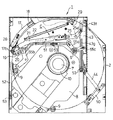
図2は、このディスク装置1のシャーシケース2の天板部分を除去した状態の平面図であり、その斜視図を図3に示す。同図において、シャーシケース2内にはベースパネル6が配設されており、その中央から斜め下方への配置状態でディスクDを回転駆動するディスクドライブ機構Aが設けられている。このディスクドライブ機構Aは、ディスクDの中心孔Daをクランプまたはクランプされている状態を解除するため、水平状態で上下動可能となるようにしたフレーム部材8が既知の緩衝支持構造9により複数箇所(本実施例では3箇所)でベースパネル6に連結されている(図4・吹出図参照)。なお、フレーム部材8の駆動構造は、一端を軸支した片持ち状態とし、先端部を揺動させてクランプヘッドを上下動させるようにした方式、フレーム部材8を水平状態のまま上下動する方式がある。   FIG. 2 is a plan view of the disk device 1 with the top plate portion of the chassis case 2 removed, and a perspective view thereof is shown in FIG. In the figure, a base panel 6 is disposed in the chassis case 2, and a disk drive mechanism A for rotating the disk D in a state of being disposed obliquely downward from the center thereof is provided. In this disk drive mechanism A, a frame member 8 that can be moved up and down in a horizontal state is released at a plurality of positions by a known buffer support structure 9 in order to release the state where the center hole Da of the disk D is clamped or clamped. It is connected to the base panel 6 at three places (in this embodiment) (see FIG. 4 and the blowout view). The drive structure of the frame member 8 is a cantilever state in which one end is pivotally supported, the tip part is swung and the clamp head is moved up and down, and the frame member 8 is moved up and down in a horizontal state. There is.

前記フレーム部材8の先端には、搬入して停止したディスクDの中心に対応する位置にクランプヘッド7が配置される。このクランプヘッド7はターンテーブルと一体に構成され、直下に配したスピンドルモータ11の駆動軸に固定されており、このスピンドルモータ11によりクランプヘッド7にクランプされたディスクDを回転駆動してドライブし、情報の記録/再生が行われる。   At the tip of the frame member 8, a clamp head 7 is disposed at a position corresponding to the center of the disk D that has been loaded and stopped. The clamp head 7 is formed integrally with the turntable and is fixed to a drive shaft of a spindle motor 11 arranged immediately below. The disk D clamped to the clamp head 7 is driven by the spindle motor 11 and driven. Information recording / reproduction is performed.

つぎに、符号Bはフレーム部材8に支持されたヘッドユニットであり、光ピックアップ12をディスクDの直径方向に往復動させるためのキャリアブロック13が、その両端をフレーム部材に固定されたガイドシャフト14・15に支持され、スレッドモータ16およびギヤユニット(図示省略)により往復動される。符号17はディスクDを装置内部へ案内するとともに装置外部へ押し出す動作を司るディスク支持アームであり、その先端にはディスクDの端部を支持するホルダー18が固定されている。   Next, a symbol B is a head unit supported by the frame member 8, and a carrier block 13 for reciprocating the optical pickup 12 in the diameter direction of the disk D is a guide shaft 14 having both ends fixed to the frame member. -It is supported by 15 and is reciprocated by a thread motor 16 and a gear unit (not shown). Reference numeral 17 denotes a disk support arm that guides the disk D into the apparatus and pushes it out of the apparatus. A holder 18 that supports the end of the disk D is fixed to the tip of the disk support arm.

つぎに、前記ディスク支持アーム17を揺動させる駆動機構Cについて説明する。ディスク支持アーム17の揺動支点となる端部は、ベースパネル6裏面で図4に示すように支持板19と一体となっており、この支持板19が枢支ピン20により旋回可能となるようにしているため、この支持板19の旋回に伴ってベースパネル6上のディスク支持アーム17がスリット6aの範囲内で揺動する。   Next, the drive mechanism C that swings the disk support arm 17 will be described. As shown in FIG. 4, the end serving as the swing fulcrum of the disk support arm 17 is integrated with the support plate 19 as shown in FIG. 4, and the support plate 19 can be turned by the pivot pin 20. Therefore, the disk support arm 17 on the base panel 6 swings within the range of the slit 6a as the support plate 19 turns.

図6は、ディスク支持アーム17の駆動機構Cが構成されている平面状態をベースパネル6を除去して示したもので、ディスク支持アーム17を直接駆動する第1のリンクアーム21は支持板19の枢支ピン17bにより連結されており、引張コイルバネ22により常時付勢されている。一方、第2のリンクアーム23には図7に示すようにスリット23a・23bが形成されており、このスリット23a・23bからリベットピン24が挿通され、その先端が第1のリンクアーム21の通孔21a・21bに固定され、第1のリンクアーム21と第2のリンクアーム23はスリット23a・23bの範囲内で伸縮可能に一体化されている。なお、第1のリンクアーム21と第2のリンクアーム23には、後述するロック機構が作用する切欠部21c・23cが形成されている。   FIG. 6 shows a planar state in which the drive mechanism C of the disk support arm 17 is configured with the base panel 6 removed, and the first link arm 21 that directly drives the disk support arm 17 is the support plate 19. Are connected by a pivot pin 17b and are always urged by a tension coil spring 22. On the other hand, slits 23 a and 23 b are formed in the second link arm 23 as shown in FIG. 7, and rivet pins 24 are inserted through the slits 23 a and 23 b, and their tips pass through the first link arm 21. The first link arm 21 and the second link arm 23 are fixed to the holes 21a and 21b, and are integrated in a stretchable manner within the range of the slits 23a and 23b. The first link arm 21 and the second link arm 23 are formed with notches 21c and 23c on which a lock mechanism described later acts.

符号25は第2のリンクアーム23に駆動力を伝達するためのレバーアームであり、支点となる通孔25aが枢支ピン25dで支持され、揺動可能となるようにしている。レバーアーム25の作用端には枢支ピン25bが固定されており、この枢支ピン25bは第2のリンクアーム23の通孔23dおよびロックレバー26の通孔26aに挿通される。そして、前記第2のリンクアーム23とロックレバー26の間には捻りコイルバネ27が配置され、その一端27aが第2のリンクアーム23の凹欠部23eに係止され、他端27bはロックレバー26の凹欠部26bに係止される。これによりロックレバー26の係止端26cは第1のリンクアーム21の切欠部21cと第2のリンクアーム23の切欠部23cと係合する方向に付勢される。なお、ベースパネル6の裏面には第1のリンクアーム21が所定の角度となったとき、その後端部で作動されるリミットスイッチ28、そして第2のリンクアームが所定の位置に達したとき、ロックレバー26の後端部26dを押圧するための起動ピン29が配設されている。   Reference numeral 25 denotes a lever arm for transmitting a driving force to the second link arm 23. A through hole 25a serving as a fulcrum is supported by a pivot pin 25d so as to be swingable. A pivot pin 25 b is fixed to the working end of the lever arm 25, and the pivot pin 25 b is inserted into the through hole 23 d of the second link arm 23 and the through hole 26 a of the lock lever 26. A torsion coil spring 27 is disposed between the second link arm 23 and the lock lever 26, one end 27a of the second link arm 23 is engaged with the recess 23e, and the other end 27b is a lock lever. It is latched by the recessed part 26b of 26. As a result, the locking end 26 c of the lock lever 26 is biased in a direction to engage with the cutout portion 21 c of the first link arm 21 and the cutout portion 23 c of the second link arm 23. When the first link arm 21 has a predetermined angle on the back surface of the base panel 6, when the limit switch 28 operated at the rear end thereof and the second link arm reach a predetermined position, An activation pin 29 for pressing the rear end portion 26d of the lock lever 26 is provided.

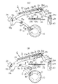
つぎに、ディスク支持アーム17の駆動機構Cへの動力伝達要素となるスライダー機構および搬送機構Eの構成について説明する。まず、搬送機構Eは、大別してローディングギヤユニットG1とラックギヤユニットG2の組み合わせにより構成されている。図8および図9は、ローディングギヤユニットG1の構成および動作態様を説明するための図である。同図において符号30は動力源となるローディングモータであり、このローディングモータ30の出力軸にはウォームギヤ31が同軸で回転するように固定され、このウォームギヤ31の回転力がギヤベース35に軸支されたダブルギヤ32・33・34へ順次、小径ギヤから大径ギヤへ減速されながら伝達される。   Next, the configuration of the slider mechanism and the transport mechanism E, which serve as a power transmission element to the drive mechanism C of the disk support arm 17, will be described. First, the transport mechanism E is roughly configured by a combination of a loading gear unit G1 and a rack gear unit G2. 8 and 9 are diagrams for explaining the configuration and operation mode of the loading gear unit G1. In the figure, reference numeral 30 denotes a loading motor as a power source. A worm gear 31 is fixed to the output shaft of the loading motor 30 so as to rotate coaxially, and the rotational force of the worm gear 31 is pivotally supported by the gear base 35. The signals are transmitted to the double gears 32, 33, and 34 while being decelerated from the small diameter gear to the large diameter gear.

前記ギヤ構成において、ダブルギヤ32はウォームギヤ31との噛合状態を解除するリリース機構を備える。これは、ダブルギヤ32を保持しつつ上下方向にスライド可能のホルダー36の端部36aが枢支ピン37に挿通され、圧縮コイルバネ38により下方へ付勢されて軸支されていることにより、定常の状態においては、図8(C)に示すようにウォームギヤ31とダブルギヤ32は正常な噛合状態となる。なお、ホルダー36のローディングモータ30側の端部には、ドグヘッド36bが形成されており、ギヤベース35に固定されたリミットスイッチ39のノブ39aを作動可能となるようにしている。   In the gear configuration, the double gear 32 includes a release mechanism that releases the meshed state with the worm gear 31. This is because the end portion 36a of the holder 36 that is slidable in the vertical direction while holding the double gear 32 is inserted into the pivot pin 37 and is urged downward by the compression coil spring 38 to be pivotally supported. In this state, as shown in FIG. 8C, the worm gear 31 and the double gear 32 are in a normal meshing state. A dog head 36b is formed at the end of the holder 36 on the side of the loading motor 30 so that a knob 39a of a limit switch 39 fixed to the gear base 35 can be operated.

前記ホルダー36の端部36aの下面には枢支ピン37と同軸で軸支されたスライダー部材40が設けられている。このスライダー部材40の枢支ピン37に軸支される部分には長溝40aが形成されており、ホルダー36の端部36aと直角方向にスライド可能となるようにしている。また、このスライダー部材40は、前端と後端との間に傾斜面40bが形成されており、スライダー部材40を前進させたときは、この傾斜面40bがホルダー36の端部36aを底面から押し上げ、ホルダー36全体が上昇する。   On the lower surface of the end portion 36 a of the holder 36, a slider member 40 that is pivotally supported coaxially with the pivot pin 37 is provided. A long groove 40 a is formed in a portion of the slider member 40 that is pivotally supported by the pivot pin 37, so that the slider member 40 can slide in a direction perpendicular to the end 36 a of the holder 36. In addition, the slider member 40 has an inclined surface 40b formed between the front end and the rear end. When the slider member 40 is advanced, the inclined surface 40b pushes up the end portion 36a of the holder 36 from the bottom surface. The entire holder 36 is raised.

スライダー部材40の後端には枢支ピン41に軸支される係止段部40cを備えた長溝40dが形成されており、さらに後端部に突起40eを備えた作用片40fが形成されている。一方、スライダー部材40の前端部にはラックギヤユニットG2の動きに応じて起動されるリセット片40gが形成されている。   A long groove 40d having a locking step 40c that is pivotally supported by the pivot pin 41 is formed at the rear end of the slider member 40, and an action piece 40f having a protrusion 40e is formed at the rear end. Yes. On the other hand, a reset piece 40g that is activated in accordance with the movement of the rack gear unit G2 is formed at the front end of the slider member 40.

このように一体に構成されたスライダー部材40は、そのフック片40hとギヤベース35のフック片35aとの間にトグル作用を与えるための引張コイルバネ42が傾斜角を具えて張設されており、スライダー部材40が常時後退しつつ反時計廻り方向に転回するように付勢されている。   The slider member 40 integrally configured in this way has a tension coil spring 42 provided with a tilt angle between the hook piece 40h and the hook piece 35a of the gear base 35 so as to have a tilt angle. The member 40 is urged so as to rotate counterclockwise while always retracting.

以上のようにスライダー部材40が構成されていることにより、図8に示す定常状態においては、スライダー部材40は枢支ピン37を支点としている。この状態において、スライダー部材40を後端部から押圧して前進させ、枢支ピン41の長溝40dの係止段部40cに至ると、前記引張コイルバネ42の張力によりスライダー部材40が枢支ピン37を支点にして転回し、図9に示すように係止段部40cと枢支ピン41が係合してロック状態となり、その姿勢が維持されることになる。   Since the slider member 40 is configured as described above, the slider member 40 uses the pivot pin 37 as a fulcrum in the steady state shown in FIG. In this state, when the slider member 40 is pushed forward from the rear end portion and reaches the locking step portion 40c of the long groove 40d of the pivot pin 41, the slider member 40 is pivoted by the tension of the tension coil spring 42. As shown in FIG. 9, the locking step portion 40c and the pivot pin 41 are engaged with each other to be locked, and the posture is maintained.

つぎに、ラックギヤユニットG2は図10に示すようにローディングスライダー43にギヤ列43a・43bが一体に形成されており、前記ギヤ列43aはローディングギヤユニットG1のダブルギヤ34の小径ギヤと噛合する。したがって、ローディングモータ30を駆動することにより、ローディングスライダー43はシャーシケース2内で前進または後退することになる。このようにローディングスライダー43を前進または後退させることにより、このローディングスライダー43の先端に連結されている駆動機構Cが駆動してディスク支持アーム17が揺動するとともに、図2に示すベースパネル6面でローディングスライダーに連結されているレバーアーム44により誘引アーム50が揺動されることになる。   Next, as shown in FIG. 10, in the rack gear unit G2, gear trains 43a and 43b are integrally formed with the loading slider 43, and the gear train 43a meshes with the small-diameter gear of the double gear 34 of the loading gear unit G1. Therefore, by driving the loading motor 30, the loading slider 43 moves forward or backward in the chassis case 2. When the loading slider 43 is moved forward or backward in this way, the drive mechanism C connected to the tip of the loading slider 43 is driven to swing the disk support arm 17 and the surface of the base panel 6 shown in FIG. Thus, the attracting arm 50 is swung by the lever arm 44 connected to the loading slider.

このように構成されたローディングスライダー43上には、このローディングスライダー43の先端部で前進後退するギヤ部材45が遊動状態で配置され、このギヤ部材45を押圧して前進させるため、前後にブロック46a・46bを備えた押圧ピン46が配置されている。そして、前記ギヤ列43bとギヤ部材45を、ギヤフレーム48に自由回転するように取り付けられているダブルギヤ47に噛合させて連結されている。この場合、ダブルギヤ47の大径ギヤ47aはギヤ列43bの後端部に噛合し、小径ギヤ47bは前記ブロック46bと一体に成形されたギヤ部材45の先端部に噛合するようにする。   On the loading slider 43 configured in this manner, a gear member 45 that moves forward and backward at the tip end of the loading slider 43 is arranged in a floating state, and the block 46a is moved forward and backward to press and advance the gear member 45. -The pressing pin 46 provided with 46b is arrange | positioned. The gear train 43b and the gear member 45 are engaged with and coupled to a double gear 47 attached to the gear frame 48 so as to freely rotate. In this case, the large-diameter gear 47a of the double gear 47 meshes with the rear end portion of the gear train 43b, and the small-diameter gear 47b meshes with the front end portion of the gear member 45 formed integrally with the block 46b.

したがって、押圧ピン46を介した外力によりギヤ部材45が押し込まれると、ダブルギヤ47は定位置で回転するため、ギヤ列43bに大径ギヤ47aの回転力が伝達し、ローディングスライダー43が移動する。なお、符号49は上述したローディングギヤユニットG1のスライダー部材40の前端部に形成されているリセット片40gを押圧する作用片であり、ローディングギヤユニットG1が図9に示す状態において、この作用片49がスライダー部材40のリセット片40gを押圧すると、枢支ピン41と係止段部40cとの係合が解除されることから、図8に示す状態に復帰する。   Therefore, when the gear member 45 is pushed in by an external force via the pressing pin 46, the double gear 47 rotates at a fixed position, so that the rotational force of the large-diameter gear 47a is transmitted to the gear train 43b, and the loading slider 43 moves. Reference numeral 49 denotes an action piece for pressing the reset piece 40g formed at the front end portion of the slider member 40 of the loading gear unit G1 described above. When the loading gear unit G1 is in the state shown in FIG. When the reset piece 40g of the slider member 40 is pressed, the engagement between the pivot pin 41 and the locking step portion 40c is released, so that the state shown in FIG. 8 is restored.

つきに、フレーム部材8の昇降機構の構成ならびに動作態様について説明する。この昇降機構は、ローディングスライダー43およびこのローディングスライダー43に同期して前進後退するスライド部材51・52、そして、前記ローディングスライダー43、スライド部材51・52に形成されたカム溝に案内される従動ピン53により構成される。前記スライド部材51はリンク部材55aによりローディングスライダー43と連結され、また、スライド部材51はリンク部材55bによりスライド部材52に連結されている。これによりローディングスライダー43、スライド部材51・52が同期して前進後退するようにしている。図4はローディングスライダー43が最も前進した状態であり、図5は最も後退している状態を示す。   Finally, the configuration and operation mode of the lifting mechanism of the frame member 8 will be described. The elevating mechanism includes a loading slider 43, slide members 51 and 52 that move forward and backward in synchronization with the loading slider 43, and driven pins that are guided by cam grooves formed in the loading slider 43 and the slide members 51 and 52. 53. The slide member 51 is connected to the loading slider 43 by a link member 55a, and the slide member 51 is connected to the slide member 52 by a link member 55b. As a result, the loading slider 43 and the slide members 51 and 52 are moved forward and backward synchronously. FIG. 4 shows a state where the loading slider 43 is most advanced, and FIG. 5 shows a state where it is most retracted.

フレーム部材8に固定された従動ピン53は、その開放端がローディングスライダー43およびスライド部材51・52に形成されたカム溝に各々係合するように配置されている。この従動ピン53と各々のカム溝との係合関係は共通するので、以下においては、ローディングスライダー43のカム溝と従動ピン53との係合関係を代表例として説明する。   The driven pins 53 fixed to the frame member 8 are arranged so that their open ends engage with cam grooves formed in the loading slider 43 and the slide members 51 and 52, respectively. Since the engagement relationship between the driven pin 53 and each cam groove is common, the engagement relationship between the cam groove of the loading slider 43 and the driven pin 53 will be described below as a representative example.

まず、図11乃至図17に示す実施例においては、フレーム部材8に固定された従動ピン53に柔軟性を具備した弾性リング54を装着するようにしている。一方、ローディングスライダー43に形成したカム溝は、従動ピン53が摺接して案内されるカム溝43cと、この従動ピン53がカム溝43cにより案内されている過程で、前記弾性リング54が接触しない程度の遊嵌状態とするカム溝43dとの二重カム構造となるように形成されている。   First, in the embodiment shown in FIGS. 11 to 17, an elastic ring 54 having flexibility is attached to the driven pin 53 fixed to the frame member 8. On the other hand, the cam groove formed in the loading slider 43 is not in contact with the cam groove 43c in which the driven pin 53 is slidably guided and in the process in which the driven pin 53 is guided by the cam groove 43c. It is formed so as to have a double cam structure with a cam groove 43d that is in a loose fit state.

前記カム溝43c・43dの高位部P2では、弾性リング54を保持すべくカム溝43dは弾性リング54の直径とほぼ同等となるように形成されており、また、カム溝43cは高位部P2の入り口付近でその溝形成が終了し、高位部P2に開口する状態となつている。したがって、カム溝43cが形成されている範囲においては、このカム溝43cで従動ピン53が規制支持され、高位部P2に至ると弾性リング54を介して従動ピン53が支持されることになる。   In the high level portion P2 of the cam grooves 43c and 43d, the cam groove 43d is formed to be substantially equal to the diameter of the elastic ring 54 in order to hold the elastic ring 54, and the cam groove 43c is formed in the high level portion P2. The groove formation is completed in the vicinity of the entrance, and the state is opened to the high-order part P2. Therefore, in the range where the cam groove 43c is formed, the driven pin 53 is regulated and supported by the cam groove 43c, and the driven pin 53 is supported via the elastic ring 54 when reaching the high position portion P2.

つぎに、以上のように構成されたフレーム部材8の昇降機構の動作態様を図11乃至図17にもとづいて説明する。図11はディスクDがディスク装置1内に搬入され、ディスクDの中心孔Daがクランプヘッドに正対する位置で停止した最も初期の状態を示す。この状態において従動ピン53はカム溝43cの低位部P1にあるため、フレーム部材8は最も降下しており、クランプヘッド7は上昇を待機している状態にある。この状態からローディングスライダ43が後退を開始すると、図12に示すように従動ピン53がカム溝43cの傾斜部P3に案内されて次第に上昇し、これに伴いフレーム部材8およびクランプヘッド7も上昇を開始する。   Next, an operation mode of the lifting mechanism of the frame member 8 configured as described above will be described with reference to FIGS. FIG. 11 shows an initial state in which the disk D is carried into the disk apparatus 1 and stopped at a position where the center hole Da of the disk D faces the clamp head. In this state, since the driven pin 53 is in the lower position P1 of the cam groove 43c, the frame member 8 is most lowered, and the clamp head 7 is in a state of waiting for ascending. When the loading slider 43 starts to retreat from this state, the driven pin 53 is guided by the inclined portion P3 of the cam groove 43c and gradually rises as shown in FIG. 12, and the frame member 8 and the clamp head 7 are also raised accordingly. Start.

そして、カム溝43cに案内されている従動ピン53が図13に示すごとくさらに傾斜部P3を上昇すると、クランプヘッド7のチャック爪7aがディスクDの中心孔Daの開口端部に当接する。この状態から図14に示すごとくクランプヘッド7が上昇すると、そのチャック爪7aがディスクDを押し上げ、その中心孔Daの開口端部をシャーシケース2の開口2aの凸部2bに押し付ける。さらに、従動ピン53が案内されて図15に示すようにカム溝43cの頂部に至ると、クランプヘッド7がディスクDの中心孔Daに嵌入し、そのチャック爪7aがディスクDの開口端部で係止してターンテーブル10上にディスクDを固定し、クランプを完了する。   When the driven pin 53 guided in the cam groove 43c further moves up the inclined portion P3 as shown in FIG. 13, the chuck claw 7a of the clamp head 7 comes into contact with the opening end portion of the center hole Da of the disk D. When the clamp head 7 ascends from this state as shown in FIG. 14, the chuck claw 7 a pushes up the disk D and presses the opening end of the center hole Da against the convex part 2 b of the opening 2 a of the chassis case 2. Further, when the driven pin 53 is guided and reaches the top of the cam groove 43c as shown in FIG. 15, the clamp head 7 is fitted into the center hole Da of the disk D, and the chuck claw 7a is at the opening end of the disk D. The disk D is locked and the disk D is fixed on the turntable 10 to complete the clamping.

図15の状態からさらにローディングスライダ43が後退するフレーム部材8は僅かに降下し、図16に示すごとく弾性リング54が高位部P2に収まる。このようにして従動ピン53がカム溝43cから離脱してこのカム溝43cによる規制支持が解除されるとともに、弾性リング54により従動ピン53が弾性支持されることになり、フレーム部材8に対する緩衝作用が発生することになる。   The frame member 8 from which the loading slider 43 further retreats from the state of FIG. 15 is slightly lowered, and the elastic ring 54 is accommodated in the high-order part P2 as shown in FIG. In this way, the driven pin 53 is detached from the cam groove 43c, the restriction support by the cam groove 43c is released, and the driven pin 53 is elastically supported by the elastic ring 54. Will occur.

図17は、ディスクDを搬出する工程を示す図であり、ローディングスライダー43を前進させることにより従動ピン53が前述とは逆の工程を辿り、低位部P1に至る過程でクランプ解除ピン56によりディスクDはクランプヘッドから離脱し、装置外部への搬出が可能となる。なお、以上で説明した動作態様の理解を容易とするため、図18にディスクDをクランプする工程を示し、図19にディスクDのクランプを解除する工程を連続的に示す。   FIG. 17 is a diagram illustrating a process of unloading the disk D. When the loading slider 43 is moved forward, the driven pin 53 follows a process opposite to that described above, and the disk is released by the clamp release pin 56 in the process of reaching the lower position P1. D is detached from the clamp head and can be carried out of the apparatus. In order to facilitate understanding of the operation mode described above, FIG. 18 shows a process of clamping the disk D, and FIG. 19 shows a continuous process of releasing the clamp of the disk D.

つぎに、ローディングスライダー43により駆動される誘引アーム50の構成ならびに動作態様を以下に説明する。図20は、誘引アーム50を駆動する構成を示すもので、ローディングスライダー43に形成された誘導溝43eに重合する位置のベースパネル6にガイドスリット6bが形成され、前記誘導溝43eとガイドスリット6bにレバーアーム44の先端に固定した従動ピン57を差し込んだ状態としてあり、前進後退する誘導溝43eに対する定位置にあるガイドスリット6bとが相互に作用して前記従動ピン57を動作制御するようにしている。   Next, the configuration and operation mode of the attracting arm 50 driven by the loading slider 43 will be described below. FIG. 20 shows a configuration for driving the attracting arm 50. A guide slit 6b is formed in the base panel 6 at a position overlapping with the guide groove 43e formed in the loading slider 43, and the guide groove 43e and the guide slit 6b are formed. The driven pin 57 fixed to the tip of the lever arm 44 is inserted, and the guide slit 6b located at a fixed position with respect to the guide groove 43e moving forward and backward interacts to control the operation of the driven pin 57. ing.

前記誘引アーム50は、図21に示すように枢支ピン58で回転可能に支持された基端部にレバーアーム44が枢支ピン59で軸支されている。誘引アーム50の先端にはディスクDの保持溝が形成されており、この保持溝内部にローラ60が配設されている。誘引アーム50はこのように構成されていることから、レバーアーム44の動作に伴いシャーシケース2内で揺動し、ディスクDを装置内部へ搬入可能となるようにしている。   As shown in FIG. 21, the pulling arm 50 has a lever arm 44 pivotally supported by a pivot pin 59 at a base end portion rotatably supported by a pivot pin 58. A holding groove for the disk D is formed at the tip of the attracting arm 50, and a roller 60 is disposed inside the holding groove. Since the attracting arm 50 is configured in this way, it swings within the chassis case 2 with the operation of the lever arm 44 so that the disk D can be carried into the apparatus.

図21乃至図25は、前記誘引アーム50の動作態様を示すもので、ローディングスライダー43のカム溝43cで導かれる従動ピン53の動作態様に対応させて説明する。図21は、ディスクDがディスク装置1内へ操作者により挿入された状態であり、このディスクDの搬入方向の前端側で押し戻されてディスク支持アーム17が後方へ揺動し、第1のリンクアーム21がリミットスイッチ28を作動して駆動機構Cが動作を開始する初期状態にある。したがって、ローディングスライダー43は同図(A)に示すように最前端に位置し、レバーアーム44の従動ピン57は同図(B)に示すように誘導溝43eの後端位置にある。   FIGS. 21 to 25 show the operation mode of the attracting arm 50 and will be described in correspondence with the operation mode of the driven pin 53 guided by the cam groove 43 c of the loading slider 43. FIG. 21 shows a state in which the disk D has been inserted into the disk device 1 by the operator. The disk D is pushed back on the front end side in the loading direction of the disk D, and the disk support arm 17 swings rearward. The arm 21 is in an initial state where the limit switch 28 is operated and the drive mechanism C starts operating. Accordingly, the loading slider 43 is positioned at the foremost end as shown in FIG. 6A, and the driven pin 57 of the lever arm 44 is at the rear end position of the guide groove 43e as shown in FIG.

かかる状態において、駆動機構Cが動作を開始すると、図22に示すようにローディングスライダー43が後退を開始する。このとき、従動ピン57は誘導溝43eの後端の傾斜面とガイドスリット6bの側壁で挟持される状態にあるため、ローディングスライダー43の後退に伴って従動ピン57も後退し、レバーアーム44が牽引されることにより誘引アーム50が揺動してディスク支持アーム17とによりディスクDをチャッキングした状態となり、ディスクDの搬入が開始される。このとき、従動ピン53は図22(B)に示すようにカム溝43cの低位部P1の水平部分を移動しており、高さは変化しない。   In this state, when the drive mechanism C starts operating, the loading slider 43 starts to move backward as shown in FIG. At this time, since the driven pin 57 is sandwiched between the inclined surface of the rear end of the guide groove 43e and the side wall of the guide slit 6b, the driven pin 57 is also retracted as the loading slider 43 is retracted, and the lever arm 44 is By being pulled, the attracting arm 50 swings and the disk D is chucked by the disk support arm 17, and the loading of the disk D is started. At this time, the driven pin 53 is moving in the horizontal portion of the lower portion P1 of the cam groove 43c as shown in FIG. 22B, and the height does not change.

図23は、ローディングスライダー43がさらに後退し、従動ピン57がガイドスリット6bの頂部に至った状態を示すもので、誘引アーム50の揺動によりディスクDの搬入が継続され、ディスクDの中心孔Daがクランプヘッド7と一致する位置に達した状態であり、このとき、従動ピン53は図23(B)に示すようにカム溝43cの傾斜部P3の上り勾配を上昇し始める。   FIG. 23 shows a state where the loading slider 43 is further retracted and the driven pin 57 reaches the top of the guide slit 6b. The loading of the disk D is continued by the swinging of the attracting arm 50, and the center hole of the disk D is shown. In this state, Da reaches a position that coincides with the clamp head 7. At this time, the driven pin 53 starts to increase the upward slope of the inclined portion P3 of the cam groove 43c as shown in FIG.

図24は、ローディングスライダー43が図23の位置から僅かに後退した状態を示し、従動ピン57が誘導溝43eによりガイドスリット6bの頂部の横溝に押し込まれる状態にある。このとき、従動ピン53は図24(B)に示すようにカム溝43cの傾斜部P3の頂部に達し、クランプヘッド7がディスクDの中心孔Daのクランプを完了する。   FIG. 24 shows a state where the loading slider 43 is slightly retracted from the position of FIG. 23, and the driven pin 57 is pushed into the lateral groove at the top of the guide slit 6b by the guide groove 43e. At this time, the driven pin 53 reaches the top of the inclined portion P3 of the cam groove 43c as shown in FIG. 24B, and the clamp head 7 completes the clamping of the center hole Da of the disk D.

図25は、ローディングスライダー43が最終位置まで後退した状態であり、図24から図25に至る過程において従動ピン57が誘導溝43e前端の長溝によりガイドスリット6bの頂部の横溝へさらに押し込まれる。これにより、誘引アーム50は同図の仮想線で示す位置から僅かに後退し、ディスクDのチャッキングを解除する。このとき、従動ピン53は図25(B)に示すようにカム溝43cの頂部から高位部P2へ降下し、ディスクDの回転駆動が可能な状態となる。   FIG. 25 shows a state in which the loading slider 43 is retracted to the final position. In the process from FIG. 24 to FIG. 25, the driven pin 57 is further pushed into the lateral groove at the top of the guide slit 6b by the long groove at the front end of the guide groove 43e. As a result, the attracting arm 50 is slightly retracted from the position indicated by the phantom line in the drawing, and the chucking of the disk D is released. At this time, the driven pin 53 descends from the top of the cam groove 43c to the high-order part P2 as shown in FIG. 25B, and the disk D can be driven to rotate.

図26乃至図30は、ディスク支持アーム17と誘引アーム50が同期して駆動する状態を示すもので、図21乃至図25の工程の説明に対応するものである。   26 to 30 show a state in which the disk support arm 17 and the attracting arm 50 are driven in synchronization, and correspond to the description of the steps of FIGS. 21 to 25.

つぎに、ディスク支持アーム17の動作態様について説明する。ディスク支持アーム17を駆動するための駆動機構Cは、図7に示す機構要素が組み立てられて構成されるのであるが、その動作はローディングスライダー43の前進後退に伴いなされる。即ち、図31において、ローディングスライダー43に形成されたガイド溝43fにレバーアーム25の端部に固定された従動ピン25cが装着され、前記ガイド溝43fに案内されるようにしている。同図に示した状態は、操作者がディスクDをスロット3aから挿入し、その前端がディスク支持アーム17の先端のホルダー18の受端部18aに収まった状態の初期状態を示す。この時点では、ロックレバー26の後端部26dが起動ピン29で押圧されていることから、その係止端26cが第1、第2のリンクアーム21・23の切欠部21c・23cに介在していない状態となる。   Next, the operation mode of the disk support arm 17 will be described. The drive mechanism C for driving the disk support arm 17 is constructed by assembling the mechanism elements shown in FIG. 7, and its operation is performed as the loading slider 43 moves forward and backward. That is, in FIG. 31, a driven pin 25c fixed to the end of the lever arm 25 is attached to a guide groove 43f formed in the loading slider 43 so as to be guided by the guide groove 43f. The state shown in the figure shows an initial state in which the operator inserts the disk D from the slot 3 a and the front end thereof is accommodated in the receiving end 18 a of the holder 18 at the tip of the disk support arm 17. At this time, since the rear end portion 26d of the lock lever 26 is pressed by the activation pin 29, the locking end 26c is interposed in the notches 21c and 23c of the first and second link arms 21 and 23. Not in a state.

図32は、操作者がディスクDを装置内部へさらに押し込んだ状態を示すもので、ディスク支持アーム17が後方へ揺動し、このディスク支持アーム17の基端部に枢支ピン17bで連結されている第1のリンクアーム21が牽引され、リミットスイッチ28が作動された状態を示す。このとき、レバーアーム25は静止しているローディングスライダー43に連結されているので、これに連結されている第2のリンクアーム23は定位置に保たれた状態となっている。したがって、第1のリンクアーム21は第2のリンクアームに対してアンロックの状態であり、同図に示すように第1のリンクアーム21が第2のリンクアーム23上でスライドして伸びている状態となる。   FIG. 32 shows a state in which the operator further pushes the disk D into the apparatus. The disk support arm 17 swings backward, and is connected to the base end of the disk support arm 17 by a pivot pin 17b. The first link arm 21 is pulled and the limit switch 28 is activated. At this time, since the lever arm 25 is connected to the stationary loading slider 43, the second link arm 23 connected to the lever slider 25 is kept in a fixed position. Therefore, the first link arm 21 is unlocked with respect to the second link arm, and the first link arm 21 slides and extends on the second link arm 23 as shown in FIG. It becomes a state.

図33は、前記により作動したリミットスイッチ28からの信号にもとづいて搬送機構Eが駆動を開始し、ローディングスライダー43が後退した状態である。この状態は、ローディングスライダー43の後退に伴い、そのガイド溝43fによりレバーアーム25が揺動され、第2のリンクアーム23が第1のリンクアーム21に追従するようにスライドして前進するため、起動ピン29による押圧から開放されたロックレバー26の係止端26cは、第1、第2のリンクアーム21・23の切欠部21c・23cに介在することになり、第1、第2のリンクアーム21・23の一体化がロックされた状態となる。即ち、ディスクDの搬入時には、第1、第2のリンクアーム21・23は、一旦は伸びる方向に変位(図31の状態から図32の状態へ)してから、縮む方向に変位(図32の状態から図33の状態へ)して第1、第2のリンクアーム21・23がロック状態となる。   FIG. 33 shows a state in which the transport mechanism E starts to be driven based on the signal from the limit switch 28 operated as described above, and the loading slider 43 is retracted. In this state, as the loading slider 43 moves backward, the lever arm 25 is swung by the guide groove 43f, and the second link arm 23 slides forward so as to follow the first link arm 21. The locking end 26c of the lock lever 26 released from the pressing by the activation pin 29 is interposed in the cutout portions 21c and 23c of the first and second link arms 21 and 23, and the first and second links. The integration of the arms 21 and 23 is locked. That is, when the disk D is loaded, the first and second link arms 21 and 23 are temporarily displaced in the extending direction (from the state shown in FIG. 31 to the state shown in FIG. 32), and then displaced in the contracting direction (FIG. 32). 33 to the state shown in FIG. 33), the first and second link arms 21 and 23 are locked.

図34は、さらにローディングスライダー43の後退に伴い、ディスク支持アーム17が後方へ揺動してディスクDを搬入し、ディスクDの中心孔Daがクランプヘッド7上に一致した状態を示す。なお、この時点までは、ホルダー18と誘引アーム50でディスクDをチャッキングして保持しており、ディスク支持アーム17と誘引アーム50は同期して揺動してくる。そして、この時点までは、リンク部材55aの従動ピン55cはローディングスライダー43のガイド溝43g内をスライドしているのみでローディングスライダー43の後退に伴う作用を受けることはない。   FIG. 34 shows a state in which the disk support arm 17 swings backward as the loading slider 43 moves backward to carry the disk D, and the center hole Da of the disk D coincides with the clamp head 7. Until this time, the disk D is chucked and held by the holder 18 and the attracting arm 50, and the disk support arm 17 and the attracting arm 50 swing in synchronization. Up to this point, the driven pin 55c of the link member 55a only slides in the guide groove 43g of the loading slider 43 and is not affected by the backward movement of the loading slider 43.

図34から図35の過程においては、レバーアーム25の従動ピン25c、ローディングスライダー43のガイド溝43fの縦溝部分をスライドするのみであるので、ディスク支持アーム17は定位置に保たれる。一方、リンク部材55aの従動ピン55cはローディングスライダー43のガイド溝43gの横溝部分で押し上げられるので、図34から図35へ至る過程でローディングスライダー43とともにスライド部材51・52がスライドし、フレーム部材8の昇降機能が動作して図35に示す時点でクランプヘッド7がディスクDの中心孔Daをクランプする。   In the process of FIGS. 34 to 35, the disk support arm 17 is maintained at a fixed position because only the driven pin 25c of the lever arm 25 and the longitudinal groove portion of the guide groove 43f of the loading slider 43 are slid. On the other hand, since the driven pin 55c of the link member 55a is pushed up by the lateral groove portion of the guide groove 43g of the loading slider 43, the slide members 51 and 52 slide together with the loading slider 43 in the process from FIG. 34 to FIG. When the lifting / lowering function is activated, the clamp head 7 clamps the center hole Da of the disk D at the time shown in FIG.

図36は、クランプヘッド7がディスクDの中心孔Daをクランプした後、ローディングスライダー43が僅かに後退した状態を示すもので、これにより、ローディングスライダー43のガイド溝43fの縦溝の終端部でレバーアーム25が僅かに揺動し、同図に示すようにディスク支持アーム17も僅かに揺動するため、ホルダー18によるディスクDのチャッキングが解除される。この時点に至ると、誘引アーム50も同期して僅かに揺動し、ディスクDのチャッキングを解除する(図25参照)。また、フレーム部材8の昇降機構では、従動ピン53がカム溝43c内で僅かに降下し、ディスクDの回転駆動が可能な状態となる(図16参照)。   FIG. 36 shows a state in which the loading slider 43 is slightly retracted after the clamp head 7 clamps the center hole Da of the disk D. Thus, at the end of the vertical groove of the guide groove 43f of the loading slider 43, FIG. The lever arm 25 slightly swings and the disk support arm 17 also slightly swings as shown in the figure, so that the chucking of the disk D by the holder 18 is released. When this point is reached, the attracting arm 50 also slightly swings in synchronism, and the chucking of the disk D is released (see FIG. 25). Further, in the elevating mechanism of the frame member 8, the driven pin 53 is slightly lowered in the cam groove 43c, and the disk D can be driven to rotate (see FIG. 16).

以上は、ディスクDの搬入時の駆動機構Cの動作態様であるが、ディスクDの搬出時は、これと逆の経路を辿り各部の機構要素は逆の動作を行う。即ち、搬送機構Eが逆に駆動され、ローディングスライダー3を前進させてディスク支持アーム17が図36の状態から図33の状態まで前方へ揺動し、図37(A)に示す状態でロックレバー26の後端部26dが起動ピン29に当接する。そして、さらにローディングスライダー43が前進すると、前記後端部26dが起動ピン29で押圧される状態となり、これにより図37(B)に示すようにロックレバー26の係止端26cが第1のリンクアーム21と第2のリンクアーム23の切欠部21c・23cから揺動して離脱し、第1のリンクアーム21と第2のリンクアーム23が一体化されたロック状態が解除され、これと同時に引張コイルバネ22の付勢力が作用してディスク支持アーム17が図37(C)に示すごとく揺動し、搬出の最終過程の最後の一瞬でディスクDをスロット3aからポップアウトして搬出を完了する。   The above is the operation mode of the drive mechanism C when the disk D is loaded, but when the disk D is unloaded, the mechanism element of each part performs the reverse operation following the reverse path. That is, the transport mechanism E is driven in reverse, the loading slider 3 is advanced, and the disk support arm 17 swings forward from the state shown in FIG. 36 to the state shown in FIG. 33. In the state shown in FIG. 26 abuts the starting pin 29. When the loading slider 43 is further advanced, the rear end portion 26d is pressed by the activation pin 29, whereby the locking end 26c of the lock lever 26 is moved to the first link as shown in FIG. The arm 21 and the second link arm 23 swing away from the notches 21c and 23c, and the lock state in which the first link arm 21 and the second link arm 23 are integrated is released. The urging force of the tension coil spring 22 acts and the disk support arm 17 swings as shown in FIG. 37C, and the disk D is popped out of the slot 3a in the final moment of the final unloading process to complete the unloading. .

つぎに、本発明の課題として前述したように、クランプヘッド7によるディスクDのクランプ動作の繰り返しにおいて、ローディングモータ30に発生する不具合を回避するための動作態様について図39を参照して以下に説明する。ローディングスライダー43が最も前進している図4に示す状態では、従動ピン53はカム溝43cに支持されてその低位部P1の始端に位置している(図26参照)。   Next, as described above as an object of the present invention, an operation mode for avoiding a problem occurring in the loading motor 30 in the repetition of the clamping operation of the disk D by the clamp head 7 will be described below with reference to FIG. To do. In the state shown in FIG. 4 in which the loading slider 43 is most advanced, the driven pin 53 is supported by the cam groove 43c and is located at the start end of the lower portion P1 (see FIG. 26).

かかる状態において、自動ローディングの開始によりローディングモータ30に正電圧(+V)の供給が開始(t1)されると、ローディングスライダー43が後退を始め、ディスクDのローディングが開始される。従動ピン53がカム溝43cの低位部P1を進行すると傾斜部P3に達し(t2/図11参照)、該傾斜部P3の作用を受けて従動ピン53、即ち、フレーム部材8の上昇が始まり(図12参照)、クランプヘッド7のチャック爪7aがディスクDの中心孔Daに接触する位置に達する(t3/図13参照)。そして、従動ピン53が傾斜部P3の頂部に達すとクランプヘッド7によるディスクDの第1回のクランプ動作が完了し(t4/図15参照)、従動ピン53が降下して高位部P2の最終位置に達する(t5/図16参照)。   In this state, when the supply of the positive voltage (+ V) to the loading motor 30 is started (t1) by the start of automatic loading, the loading slider 43 starts to move backward and the loading of the disk D is started. When the driven pin 53 advances through the lower portion P1 of the cam groove 43c, it reaches the inclined portion P3 (t2 / see FIG. 11), and the driven pin 53, that is, the frame member 8 starts to rise under the action of the inclined portion P3 ( 12), the chuck claw 7a of the clamp head 7 reaches a position where it contacts the center hole Da of the disk D (t3 / see FIG. 13). When the driven pin 53 reaches the top of the inclined portion P3, the first clamping operation of the disk D by the clamp head 7 is completed (t4 / see FIG. 15), the driven pin 53 descends and the final position of the high-order portion P2 is reached. The position is reached (t5 / see FIG. 16).

上記状態に至り、電圧を供給しない微少期間(t5〜t6)を経過すると、負電圧(−V)の供給が開始される(t6)。前記微少期間(t5〜t6)は、ローディングモータ30への電圧が遮断されてロータの回転が停止して逆起電流が消滅するまでの時間であり、本発明の構成ではローディングモータ30がローディングギヤユニットG1により大きな制動を受けるため、約60ミリ秒が過不足ない値であることを確認できた。   When the above state is reached and a minute period (t5 to t6) in which no voltage is supplied has elapsed, supply of a negative voltage (−V) is started (t6). The minute period (t5 to t6) is the time from when the voltage to the loading motor 30 is cut off and the rotation of the rotor stops and the back electromotive current disappears. In the configuration of the present invention, the loading motor 30 is loaded with the loading gear. Since the unit G1 receives a large braking, it was confirmed that about 60 milliseconds is a value that is not excessive or insufficient.

このようにして、負電圧(−V)が供給されると(t6〜t8)、ローディングモータ30は逆転を開始し、ローディングスライダー43が前進するため、クランプヘッド7が上下動し、第2回のクランプ動作を行う(t7)。したがって、この負電圧(−V)が供給される期間(t6〜t8)は、クランプヘッド7がクランプ動作を行うための上下動に必要な範囲に設定される。   In this way, when the negative voltage (−V) is supplied (t6 to t8), the loading motor 30 starts reverse rotation and the loading slider 43 moves forward, so that the clamp head 7 moves up and down, and the second time. The clamping operation is performed (t7). Accordingly, the period (t6 to t8) in which the negative voltage (−V) is supplied is set to a range necessary for the vertical movement for the clamp head 7 to perform the clamping operation.

このようにして、第2回のクランプ動作が終了すると、従動ピン53がt8の位置まで戻ることになるので、これを再び高位部P2の最終位置まで戻す必要がある。このため、負電圧(−V)が遮断されると(t8)、電圧を供給しない微少期間(t8〜t9)を経過して正電圧(+V)が供給される(t9)。この場合も、ローディングモータ30のロータの回転が停止し、この微少期間(t8〜t9)で逆起電流が消滅することになる。そして、正電圧(+V)が再度供給(t9〜t11)されることにより、第3回のクランプ動作(t10)を経て、従動ピン53が高位部P2の最終位置に戻る(t11)。   In this way, when the second clamping operation is completed, the driven pin 53 returns to the position of t8, so that it is necessary to return it to the final position of the high-order part P2. For this reason, when the negative voltage (−V) is interrupted (t8), the positive voltage (+ V) is supplied after the minute period (t8 to t9) during which no voltage is supplied (t9). Also in this case, the rotation of the rotor of the loading motor 30 is stopped, and the counter electromotive current disappears in this minute period (t8 to t9). Then, when the positive voltage (+ V) is supplied again (t9 to t11), the driven pin 53 returns to the final position of the high-order part P2 through the third clamping operation (t10) (t11).

このように、本発明では、ローディングモータ30に供給される電圧の方向が反転する遷移時に、電圧の供給が停止される微少期間を介在するようにしたので、ローディングモータ30を駆動する電流に逆起電流が重畳するのを回避することができる。図40は、かかる本発明の動作状態においてローディングモータ30に流れる電流の値の測定結果を示すもので、t5(t8)において電圧の供給が停止されると、逆起電流Ph1が発生する。そして微少期間t5〜t6(t8〜t9)が経過し、t6(t9)で供給された電圧により起動電流Ph2が流れる。   As described above, according to the present invention, since the voltage supply is stopped during the transition in which the direction of the voltage supplied to the loading motor 30 is reversed, the voltage is stopped. It is possible to avoid superposition of electromotive currents. FIG. 40 shows the measurement result of the value of the current flowing through the loading motor 30 in the operating state of the present invention. When the supply of voltage is stopped at t5 (t8), the counter electromotive current Ph1 is generated. Then, a minute period t5 to t6 (t8 to t9) elapses, and the starting current Ph2 flows by the voltage supplied at t6 (t9).

図40(A)は、前記微少期間を60ミリ秒に設定したとき発生する電流の状態を示したもので、起動電流Ph2は60ミリ秒の微少期間が経過して逆起電流Ph1が消滅してから発生するため、この逆起電流Ph1と重畳することがなく、その最大の電流値が600mAであり、従来の装置において逆起電流が重畳した場合と比較して200mA少なく電流が流れることを確認できた。なお、微少期間を30ミリ秒に設定した同測定実験では、図40(B)に示すように逆起電流が重畳して起動電流が600mA以上となる。また、微少期間を80ミリ秒に設定した同測定実験では、図40(C)に示すように、逆起電流が消滅した後に経過する不要な時間が長くなる。したがって、実験対象とした装置では微少期間を60ミリ秒に設定することが適当であることを確認できたが、この値は、ローディングモータにかかる負荷により異なるため、機種毎の測定実験で適正値を定めることが望ましい。   FIG. 40A shows the state of the current generated when the minute period is set to 60 milliseconds. The starting current Ph2 disappears after the minute period of 60 milliseconds has elapsed. Therefore, the maximum current value is 600 mA, and the current flows by 200 mA less than the case where the counter electromotive current is superimposed in the conventional device. It could be confirmed. In the same measurement experiment in which the minute period is set to 30 milliseconds, as shown in FIG. 40B, the counter electromotive current is superimposed and the starting current becomes 600 mA or more. In the same measurement experiment in which the minute period is set to 80 milliseconds, as shown in FIG. 40C, unnecessary time that elapses after the back electromotive current disappears becomes longer. Therefore, it was confirmed that it was appropriate to set the minute period to 60 milliseconds in the apparatus that was the subject of the experiment. However, this value varies depending on the load applied to the loading motor, so it is an appropriate value in the measurement experiment for each model. It is desirable to define

このように、本発明のディスク装置によれば、実質3回のクランプ動作によりディスクを確実にクランプすることができることになるが、この間、クランプヘッドを急激に動作するためのローディングモータに逆起電流が重畳した必要以上の電流が流れないようにしたので、このローディングモータの耐久性を向上することができ、平均50,000回以上の繰り返し動作でも障害の発生は確認されなかった。   As described above, according to the disk device of the present invention, the disk can be reliably clamped by substantially three clamping operations. During this time, the counter electromotive current is applied to the loading motor for operating the clamp head rapidly. Since no more current than necessary was superimposed, the durability of this loading motor could be improved, and no failure was confirmed even after an average of 50,000 or more repeated operations.

本発明を実施したディスク装置の外観を示す斜視図である。It is a perspective view which shows the external appearance of the disc apparatus which implemented this invention. 図1のディスク装置の内部構造を示す平面図である。FIG. 2 is a plan view showing an internal structure of the disk device of FIG. 1. 図1のディスク装置の内部構造を示す斜視図である。It is a perspective view which shows the internal structure of the disc apparatus of FIG. 図1のディスク装置の底面における内部構造を示す図である。It is a figure which shows the internal structure in the bottom face of the disc apparatus of FIG. 図1のディスク装置の動作状態を説明する図である。It is a figure explaining the operation state of the disk apparatus of FIG. 図1のディスク装置の動作状態を説明する図である。It is a figure explaining the operation state of the disk apparatus of FIG. 駆動機構Cの構成を説明するための分解斜視図である。4 is an exploded perspective view for explaining the configuration of a drive mechanism C. FIG. ローディングギヤユニットを説明する図である。It is a figure explaining a loading gear unit. ローディングギヤユニットの動作状態を説明する図である。It is a figure explaining the operation state of a loading gear unit. ラックギヤユニットの構成を示す斜視図である。It is a perspective view which shows the structure of a rack gear unit. 昇降機構の動作の第1工程を示す図である。It is a figure which shows the 1st process of operation | movement of a raising / lowering mechanism. 昇降機構の動作の第2工程を示す図である。It is a figure which shows the 2nd process of operation | movement of a raising / lowering mechanism. 昇降機構の動作の第3工程を示す図である。It is a figure which shows the 3rd process of operation | movement of a raising / lowering mechanism. 昇降機構の動作の第4後退を示す図である。It is a figure which shows the 4th retreat of operation | movement of a raising / lowering mechanism. 昇降機構の動作の第5工程を示す図である。It is a figure which shows the 5th process of operation | movement of a raising / lowering mechanism. 昇降機構の動作の第6工程を示す図だある。It is a figure which shows the 6th process of operation | movement of a raising / lowering mechanism. 昇降機構の動作の第7工程を示す図である。It is a figure which shows the 7th process of operation | movement of a raising / lowering mechanism. クランプヘッドの昇降動作における往路過程を示す図である。It is a figure which shows the outward process in the raising / lowering operation | movement of a clamp head. クランプヘッドの昇降動作における復路過程を示す図である。It is a figure which shows the return path process in the raising / lowering operation | movement of a clamp head. 誘引アームの作動機構の構成を示す分解斜視図である。It is a disassembled perspective view which shows the structure of the action | operation mechanism of an attracting arm. 誘引アームの動作の第1工程を示す図である。It is a figure which shows the 1st process of operation | movement of an attracting arm. 誘引アームの動作の第2工程を示す図である。It is a figure which shows the 2nd process of operation | movement of an attracting arm. 誘引アームの動作の第3工程を示す図である。It is a figure which shows the 3rd process of operation | movement of an attracting arm. 誘引アームの動作の第4工程を示す図である。It is a figure which shows the 4th process of operation | movement of an attracting arm. 誘引アームの動作の第5工程を示す図である。It is a figure which shows the 5th process of operation | movement of an attracting arm. ディスクの搬入状態の第1工程を示す図である。It is a figure which shows the 1st process of the carrying-in state of a disk. ディスクの搬入状態の第2工程を示す図である。It is a figure which shows the 2nd process of the carrying-in state of a disk. ディスクの搬入状態の第3工程を示す図である。It is a figure which shows the 3rd process of the carrying-in state of a disk. ディスクの搬入状態の第4工程を示す図である。It is a figure which shows the 4th process of the carrying-in state of a disk. ディスクの搬入状態の第5工程を示す図である。It is a figure which shows the 5th process of the carrying-in state of a disk. ディスク支持アームの動作状態の第1工程を示す図である。It is a figure which shows the 1st process of the operation state of a disk support arm. ディスク支持アームの動作状態の第2工程を示す図である。It is a figure which shows the 2nd process of the operation state of a disk support arm. ディスク支持アームの動作状態の第3工程を示す図である。It is a figure which shows the 3rd process of the operation state of a disk support arm. ディスク支持アームの動作状態の第4工程を示す図である。It is a figure which shows the 4th process of the operation state of a disk support arm. ディスク支持アームの動作状態の第5工程を示す図である。It is a figure which shows the 5th process of the operation state of a disk support arm. ディスク支持アームの動作状態の第6工程を示す図である。It is a figure which shows the 6th process of the operation state of a disk support arm. ディスク支持アームの搬出時の動作状態を説明する図である。It is a figure explaining the operation state at the time of carrying out of a disk support arm. ディスク支持アームの機能を説明する図である。It is a figure explaining the function of a disk support arm. 本発明の動作態様を説明する図である。It is a figure explaining the operation | movement aspect of this invention. ローディングモータに流れる電流の態様を説明する図である。It is a figure explaining the aspect of the electric current which flows into a loading motor. 従来のディスク装置の機能を説明する図である。It is a figure explaining the function of the conventional disc apparatus. 従来のディスク装置の機能を説明する図である。It is a figure explaining the function of the conventional disc apparatus. ディスクの中心孔の形態を説明する図である。It is a figure explaining the form of the center hole of a disc. 従来のディスク装置の動作態様を説明する図である。It is a figure explaining the operation | movement aspect of the conventional disc apparatus. 従来のディスク装置における不具合を説明する図である。It is a figure explaining the malfunction in the conventional disc apparatus.

符号の説明Explanation of symbols

1・・・・・・ディスク装置
2・・・・・・シャーシケース
3・・・・・・ベゼル
4・・・・・・押釦
5・・・・・・インジケータ
6・・・・・・ベースパネル
7・・・・・・クランプヘッド
8・・・・・・フレーム部材
9・・・・・・緩衝支持構造
10・・・・・ターンテーブル
11・・・・・スピンドルモータ
12・・・・・光ピックアップ
13・・・・・キャリアブロック
14・・・・・ガイドシャフト
15・・・・・ガイドシャフト
16・・・・・スレッドモータ
17・・・・・ディスク支持アーム
18・・・・・ホルダー
19・・・・・支持板
20・・・・・枢支ピン
21・・・・・第1のリンクアーム
22・・・・・引張コイルバネ
23・・・・・第2のリンクアーム
24・・・・・リベットピン
25・・・・・枢支ピン
26・・・・・ロックレバー
27・・・・・捻りコイルバネ
28・・・・・リミットスイッチ
29・・・・・起動ピン
30・・・・・ローディングモータ
31・・・・・ウオームギヤ
32・・・・・ダブルギヤ
33・・・・・ダブルギヤ
34・・・・・ダブルギヤ
35・・・・・ギヤベース
36・・・・・ホルダー
37・・・・・枢支ピン
38・・・・・圧縮コイルバネ
39・・・・・リミットスイッチ
40・・・・・スライダー部材
41・・・・・枢支ピン
42・・・・・引張コイルバネ
43・・・・・ローディングスライダー
44・・・・・レバーアーム
45・・・・・ギヤ部材
46・・・・・押圧ピン
47・・・・・ダブルギヤ
48・・・・・ギヤフレーム
49・・・・・作用片
50・・・・・誘引アーム
51・・・・・スライド部材
52・・・・・スライド部材
53・・・・・従動ピン
54・・・・・弾性リング
55a・・・・リンク部材
55b・・・・リンク部材
55c・・・・従動ピン
56・・・・・クランプ解除ピン
57・・・・・従動ピン
58・・・・・枢支ピン
59・・・・・枢支ピン
60・・・・・ローラ
A・・・・・・ディスクドライブ機構
B・・・・・・ヘッドユニット
C・・・・・・駆動機構
D・・・・・・ディスク
Da・・・・・中心孔
E・・・・・・搬送機構
1 .... Disk device 2 .... Chassis case 3 .... Bezel 4 .... Push button 5 .... Indicator 6 .... Base Panel 7 ... Clamp head 8 Frame member 9 Buffer support structure 10 Turntable 11 Spindle motor 12 ... -Optical pickup 13-Carrier block 14-Guide shaft 15-Guide shaft 16-Thread motor 17-Disc support arm 18- Holder 19... Support plate 20... Pivot pin 21... First link arm 22... Tension coil spring 23. .... Rivet pin 25 ... Pivot pin 26 ... Lock lever 27 ... Torsion coil spring 28 ... Limit switch 29 ... Start pin 30 ... Loading motor 31 ... Worm gear 32 ... Double gear 33 ... Double gear 34 ... Double gear 35 ... Gear base 36 ... Holder 37 ... Pivot pin 38 ... Compression coil spring 39 ... Limit switch 40 ... Slider member 41 ... Pivot pin 42 ... Tension coil spring 43 ... Loading slider 44 ... Lever Arm 45 ... Gear member 46 ... Pressing pin 47 ... Double gear 48 ... Gear frame 49 ... Operating piece 50 ... Attracting arm 51... Slide member 52... Slide member 53 .. Follower pin 54... Elastic ring 55 a... Link member 55 b.・ Follow-up pin 56 ... Clamp release pin 57 ... Follow-up pin 58 ... Pivot pin 59 ... Pivot pin 60 ... Roller A ... ··· Disk drive mechanism B ··· Head unit C ··· Drive mechanism D ··· Disk Da ··· Center hole E ··· Transport mechanism

Claims (1)

クランプヘッドを備えたターンテーブルおよびスピンドルモータからなるディスクドライブ機構を設けたフレーム部材を上下動させることにより前記クランプヘッドによりディスクの中心孔のクランプまたはクランプの解除が可能となるようにし、且つ、ディスクを本体内へローディングまたは本体外へアンローディングさせるため、該ディスクを前記フレーム部材上で支持しつつ水平方向に前進後退させる複数のアームと前記フレーム部材を上下動させる駆動機構を備え、該フレーム部材を複数回上下動させてディスクの中心孔をクランプするようにしたディスク装置において、
前記フレーム部材の駆動機構の駆動源となるローディングモータに供給される電圧の方向が反転する遷移時に、電圧の供給が停止される微少期間が介在するようにしたことを特徴とするディスク装置。
A frame member provided with a disk drive mechanism comprising a turntable having a clamp head and a spindle motor is moved up and down so that the center of the disk can be clamped or released by the clamp head, and the disk A plurality of arms for moving the frame member up and down in a horizontal direction while supporting the disk on the frame member and a drive mechanism for moving the frame member up and down. In the disk device that is moved up and down several times to clamp the center hole of the disk,
A disk device characterized in that a minute period during which voltage supply is stopped is interposed at the time of transition in which the direction of voltage supplied to a loading motor that is a drive source of the frame member drive mechanism is reversed.
JP2005308603A 2005-10-24 2005-10-24 Disk unit Pending JP2007115377A (en)

Priority Applications (1)

Application Number Priority Date Filing Date Title
JP2005308603A JP2007115377A (en) 2005-10-24 2005-10-24 Disk unit

Applications Claiming Priority (1)

Application Number Priority Date Filing Date Title
JP2005308603A JP2007115377A (en) 2005-10-24 2005-10-24 Disk unit

Publications (1)

Publication Number Publication Date
JP2007115377A true JP2007115377A (en) 2007-05-10

Family

ID=38097407

Family Applications (1)

Application Number Title Priority Date Filing Date
JP2005308603A Pending JP2007115377A (en) 2005-10-24 2005-10-24 Disk unit

Country Status (1)

Country Link
JP (1) JP2007115377A (en)

Citations (3)

* Cited by examiner, † Cited by third party
Publication number Priority date Publication date Assignee Title
JPS54156113A (en) * 1978-05-31 1979-12-08 Sony Corp Motor driving circuit
JPH01164291A (en) * 1987-09-14 1989-06-28 United Technol Corp <Utc> Apparatus and method for driving control of reversible dc motor
JP2005085449A (en) * 2003-09-11 2005-03-31 Sony Corp Disk drive device

Patent Citations (3)

* Cited by examiner, † Cited by third party
Publication number Priority date Publication date Assignee Title
JPS54156113A (en) * 1978-05-31 1979-12-08 Sony Corp Motor driving circuit
JPH01164291A (en) * 1987-09-14 1989-06-28 United Technol Corp <Utc> Apparatus and method for driving control of reversible dc motor
JP2005085449A (en) * 2003-09-11 2005-03-31 Sony Corp Disk drive device

Similar Documents

Publication Publication Date Title
JP4144563B2 (en) Disk unit
JP4687566B2 (en) Disk unit
JP4882547B2 (en) Disk unit
JP2007220276A (en) Optical equipment
JP3933080B2 (en) Disk unit
JP2002203354A (en) Recording medium mounting device
JP2006114175A (en) Disk unit
JP2007293981A (en) Disk unit
JP4325568B2 (en) Disk unit
JP4123223B2 (en) Disk unit
CN101221786B (en) Disk device
JP2007265576A (en) Disk unit
JP2007115377A (en) Disk unit
CN101118766B (en) Disk unit
JP4093118B2 (en) Disk unit
JP4265596B2 (en) Disk unit
JP3979357B2 (en) Disk unit
JP4277809B2 (en) Disk unit
JP4687688B2 (en) Disk unit
JP4259474B2 (en) Disk unit
JP4687477B2 (en) Disk unit
JP4502033B2 (en) Disk unit
JP4356802B2 (en) Disk unit
JP4315112B2 (en) Disk unit
JP4315108B2 (en) Disk unit

Legal Events

Date Code Title Description
A621 Written request for application examination

Free format text: JAPANESE INTERMEDIATE CODE: A621

Effective date: 20071218

A977 Report on retrieval

Free format text: JAPANESE INTERMEDIATE CODE: A971007

Effective date: 20101209

A131 Notification of reasons for refusal

Free format text: JAPANESE INTERMEDIATE CODE: A131

Effective date: 20101214

A02 Decision of refusal

Free format text: JAPANESE INTERMEDIATE CODE: A02

Effective date: 20110426