JP2006520904A - Inline leak detector - Google Patents
Inline leak detector Download PDFInfo
- Publication number
- JP2006520904A JP2006520904A JP2006507284A JP2006507284A JP2006520904A JP 2006520904 A JP2006520904 A JP 2006520904A JP 2006507284 A JP2006507284 A JP 2006507284A JP 2006507284 A JP2006507284 A JP 2006507284A JP 2006520904 A JP2006520904 A JP 2006520904A
- Authority
- JP
- Japan
- Prior art keywords
- package
- room
- sensor
- atmospheric pressure
- closed
- Prior art date
- Legal status (The legal status is an assumption and is not a legal conclusion. Google has not performed a legal analysis and makes no representation as to the accuracy of the status listed.)
- Pending
Links
- 238000000034 method Methods 0.000 claims abstract description 44
- 230000035945 sensitivity Effects 0.000 claims description 9
- 230000007246 mechanism Effects 0.000 claims description 8
- 230000003287 optical effect Effects 0.000 claims description 3
- 238000012360 testing method Methods 0.000 abstract description 4
- 238000001514 detection method Methods 0.000 abstract 1
- 238000004519 manufacturing process Methods 0.000 description 18
- 238000010586 diagram Methods 0.000 description 4
- 239000011888 foil Substances 0.000 description 4
- 238000007689 inspection Methods 0.000 description 3
- 238000011109 contamination Methods 0.000 description 2
- 239000007788 liquid Substances 0.000 description 2
- 239000000463 material Substances 0.000 description 2
- 239000000178 monomer Substances 0.000 description 2
- 238000004806 packaging method and process Methods 0.000 description 2
- 230000008569 process Effects 0.000 description 2
- 238000012545 processing Methods 0.000 description 2
- 230000004044 response Effects 0.000 description 2
- 239000004743 Polypropylene Substances 0.000 description 1
- XAGFODPZIPBFFR-UHFFFAOYSA-N aluminium Chemical compound [Al] XAGFODPZIPBFFR-UHFFFAOYSA-N 0.000 description 1
- 229910052782 aluminium Inorganic materials 0.000 description 1
- 230000001580 bacterial effect Effects 0.000 description 1
- 239000002131 composite material Substances 0.000 description 1
- 230000002950 deficient Effects 0.000 description 1
- 238000006073 displacement reaction Methods 0.000 description 1
- 238000004090 dissolution Methods 0.000 description 1
- 230000002209 hydrophobic effect Effects 0.000 description 1
- 238000003780 insertion Methods 0.000 description 1
- 230000037431 insertion Effects 0.000 description 1
- 230000003993 interaction Effects 0.000 description 1
- 238000005259 measurement Methods 0.000 description 1
- 230000035515 penetration Effects 0.000 description 1
- 239000004033 plastic Substances 0.000 description 1
- -1 polypropylene Polymers 0.000 description 1
- 229920001155 polypropylene Polymers 0.000 description 1
- 238000003908 quality control method Methods 0.000 description 1
- 238000009666 routine test Methods 0.000 description 1
- 238000005070 sampling Methods 0.000 description 1
Images


Classifications
-
- G—PHYSICS
- G01—MEASURING; TESTING
- G01M—TESTING STATIC OR DYNAMIC BALANCE OF MACHINES OR STRUCTURES; TESTING OF STRUCTURES OR APPARATUS, NOT OTHERWISE PROVIDED FOR
- G01M3/00—Investigating fluid-tightness of structures
- G01M3/02—Investigating fluid-tightness of structures by using fluid or vacuum
- G01M3/36—Investigating fluid-tightness of structures by using fluid or vacuum by detecting change in dimensions of the structure being tested
- G01M3/363—Investigating fluid-tightness of structures by using fluid or vacuum by detecting change in dimensions of the structure being tested the structure being removably mounted in a test cell
-
- G—PHYSICS
- G01—MEASURING; TESTING
- G01M—TESTING STATIC OR DYNAMIC BALANCE OF MACHINES OR STRUCTURES; TESTING OF STRUCTURES OR APPARATUS, NOT OTHERWISE PROVIDED FOR
- G01M3/00—Investigating fluid-tightness of structures
- G01M3/02—Investigating fluid-tightness of structures by using fluid or vacuum
- G01M3/26—Investigating fluid-tightness of structures by using fluid or vacuum by measuring rate of loss or gain of fluid, e.g. by pressure-responsive devices, by flow detectors
- G01M3/32—Investigating fluid-tightness of structures by using fluid or vacuum by measuring rate of loss or gain of fluid, e.g. by pressure-responsive devices, by flow detectors for containers, e.g. radiators
- G01M3/34—Investigating fluid-tightness of structures by using fluid or vacuum by measuring rate of loss or gain of fluid, e.g. by pressure-responsive devices, by flow detectors for containers, e.g. radiators by testing the possibility of maintaining the vacuum in containers, e.g. in can-testing machines
Landscapes
- Physics & Mathematics (AREA)
- General Physics & Mathematics (AREA)
- Examining Or Testing Airtightness (AREA)
Abstract
【課題】多数のパッケージを一度にテストして、パッケージが液漏れを起こしていないか個別に測定する装置および方法を提供すること。
【解決手段】本発明は、コンタクトレンズのパッケージなどの柔軟なカバーを持つパッケージの漏れを検出するためのインライン型のリーク検出装置を提供する。このパッケージの周囲の大気圧を低くした場合、この柔軟なカバーは電気機械的なスイッチと接触して動く。An apparatus and method for testing a number of packages at a time and individually measuring whether the packages are leaking.
The present invention provides an in-line type leak detection device for detecting leakage of a package having a flexible cover such as a contact lens package. When the atmospheric pressure around the package is lowered, the flexible cover moves in contact with the electromechanical switch.
Description
〔関連出願〕
本出願は、2003年3月17日に出願された米国仮特許出願第60/455,342号の非仮出願である。
[Related applications]
This application is a non-provisional application of US Provisional Patent Application No. 60 / 455,342, filed Mar. 17, 2003.
〔発明の分野〕
本発明は眼科用レンズの製造技術に関し、特に眼科用レンズの製造システムのための新規なインライン型リーク検出器に関するものである。
眼科用レンズの自動製造工程は、裏曲面(上部)と前曲面(下部)の型構造の間に、型穴に流し込まれたモノマーを挟むことによって各レンズを形成するものとして知られている。このモノマーは、重合(硬化)され、離型し、ハイドレーションおよび検査の後、個別にブリスター包装され、殺菌して柔軟性のあるカバーでこのパッケージを密封するなど、これらに限定されない更なる工程を必要とする。眼科用レンズおよび包装制御システム全体における模範的な先行技術の説明として、「PRODUCTION LINE TRACKING AND QUALITY CONTROL SYSTEM」という表題の米国特許第5,555,504号を参照することができるのでここに引用しておく。
(Field of the Invention)
The present invention relates to an ophthalmic lens manufacturing technique, and more particularly to a novel in-line leak detector for an ophthalmic lens manufacturing system.
An automatic manufacturing process of an ophthalmic lens is known as forming each lens by sandwiching a monomer poured into a mold cavity between a mold structure of a back curved surface (upper part) and a front curved surface (lower part). This monomer is polymerized (cured), demolded, hydrated and inspected, then individually blister packed, sterilized and sealed with a flexible cover for further steps such as, but not limited to: I need. For a description of exemplary prior art in the overall ophthalmic lens and packaging control system, reference is made to US Pat. No. 5,555,504 entitled “PRODUCTION LINE TRACKING AND QUALITY CONTROL SYSTEM”, which is incorporated herein by reference. Keep it.
レンズやその他の生産品の包装に関しては、全ての個々のブリスター包装が、その内容物に雑菌混入を防ぐ確実な密封を施してあることが極めて重要である。製造ライン上で準備される密封包装は、無作為にそのパッケージのロットを抜き取って密封されているか否かがしばしば検査される。ある通常の検査においては、可視の液状色素を入れた容器中に密封パッケージの代表的なサンプルを沈めて空気を抜く。このパッケージ内にこの色素が漏れ出すか否かを観るため、このパッケージが視覚的に監視される。このタイプのオフラインテストは多大な時間を必要とし、用意されたパッケージの大部分の完全性を確認するわけではない。さらにこのタイプの検査では、この検査液との相互作用によって、検査に合格するパッケージの外装に損傷を受け、その製品を台無しにすることがある。したがって、実用的な方法としては、パッケージがその製造ラインにある間にその製造ラインのスピードに見合う時間枠内で、パッケージの大部分が適切に密封されているか否かを判断するといった効果的な方法となる。 As for the packaging of lenses and other products, it is extremely important that all individual blister packs have a positive seal that prevents contamination of their contents. Sealed packages prepared on the production line are often inspected for random sampling of their package lots. In one routine test, a representative sample of the sealed package is submerged in a container containing a visible liquid dye. The package is visually monitored to see if the dye leaks into the package. This type of offline testing is time consuming and does not verify the integrity of most of the packages provided. Furthermore, in this type of inspection, the interaction with the inspection liquid may damage the package exterior that passes the inspection and ruin the product. Therefore, as a practical method, it is effective to determine whether most of the package is properly sealed within a time frame that matches the speed of the production line while the package is on the production line. Become a method.
〔発明の目的〕
結果的に、本発明は、製造ラインからパッケージを取り出さずに済む、密封されたパッケージ用のインライン型リーク検出器を提供することを目的とする。このパッケージは柔軟性のあるカバーを持ち、このカバーは、パッケージ周辺の大気圧を下げた状態がこの発明に特に適している場合に動くものである。また、本発明の目的は、パッケージが密封されているか否かを測定する方法を提供することである。さらに、本発明の目的は、パッケージが密封されているかどうかを判断する簡単かつ効果的な装置および方法を提供することであり、その方法はテストによってパッケージを損傷しないものである。また、本発明の目的は、パッケージが密封されているか否か判断する簡単な機械装置および方法を提供することである。さらに、本発明の目的は、多数のパッケージを一度にテストして、パッケージが液漏れを起こしていないか個別に測定する装置および方法を提供することである。また、本発明は、製造ラインの中に直接組み込みが可能なリーク検出器を提供することを目的とする。
(Object of invention)
As a result, an object of the present invention is to provide an in-line type leak detector for a sealed package that does not require removal of the package from the production line. The package has a flexible cover, which moves when the reduced atmospheric pressure around the package is particularly suitable for the present invention. It is also an object of the present invention to provide a method for measuring whether a package is sealed. Furthermore, it is an object of the present invention to provide a simple and effective apparatus and method for determining whether a package is sealed, which method does not damage the package by testing. It is also an object of the present invention to provide a simple mechanical device and method for determining whether a package is sealed. Furthermore, it is an object of the present invention to provide an apparatus and method for testing a number of packages at once and measuring individually whether the packages are leaking. Another object of the present invention is to provide a leak detector that can be directly incorporated into a production line.
〔発明および好ましい実施例の詳細な説明〕
本発明は少なくとも1つの密封されたパッケージにおける漏入を検出するための装置を含み、このパッケージは大気圧より低い気圧下にある場合に変形する蓋部を備え、この装置は、
このパッケージの装填および取り出しを可能にするために開閉可能な部屋であって、閉鎖した場合の部屋の空気を抜くことが可能若しくは大気圧に戻すことが可能な部屋と、
頭部、尾部およびセンサーを備えた少なくとも1つの機械スイッチであって、この部屋が大気圧で閉鎖された場合、頭部がこの変形可能な蓋部から第1の一定距離だけ離間して位置し、尾部がセンサーから第2の一定距離だけ離間して位置する機械スイッチと、
この機械スイッチの開閉を判断する機構と、を備える。
ここで使用する「パッケージ」という言葉は、製品を保存するために使用する容器のいかなるタイプのものでもよい。特許請求の範囲で規定したように、このようなパッケージは蓋部を備えていなければならず、この蓋部は密閉されたパッケージの周辺の空気圧が密封されたパッケージおよびその内容物の内部圧力より低減された場合に変形する。これらの変形可能な蓋部は、プラスチック、フォイル、複合材料、若しくは展性を持つ材料、好ましくはフォイルで形成される。本発明の実施例は、コンタクトレンズのためのパッケージなどの眼科用レンズのパッケージを検査するために使用される。したがって、本発明の詳細な説明のほとんどがこの実施例の具体的な説明となる。
Detailed Description of the Invention and Preferred Embodiments
The present invention includes an apparatus for detecting leaks in at least one sealed package, the package comprising a lid that deforms when under atmospheric pressure, the apparatus comprising:
A room that is openable and closable to allow loading and unloading of the package, wherein the room can be evacuated or returned to atmospheric pressure when closed;
At least one mechanical switch with a head, a tail and a sensor, wherein the head is located at a first constant distance from the deformable lid when the room is closed at atmospheric pressure. A mechanical switch whose tail is located at a second constant distance from the sensor;
A mechanism for determining whether the mechanical switch is opened or closed.
As used herein, the term “package” may be any type of container used to store a product. As defined in the claims, such a package must be provided with a lid, which is based on the air pressure around the sealed package and the internal pressure of the sealed package and its contents. Deforms when reduced. These deformable lids are made of plastic, foil, composite material or malleable material, preferably foil. Embodiments of the present invention are used to inspect packages for ophthalmic lenses, such as packages for contact lenses. Therefore, most of the detailed description of the present invention is a specific description of this embodiment.
大部分のコンタクトレンズは、ポリプロピレンなどの疎水性材料から形成される半球部と、アルミフォイルから形成されるフォイルトップを持つ、個別のブリスター包装でパッケージされる。このようなパッケージの例として、米国特許第4,691,820号、第5,054,610号、第5,337,888号、第5,375,698号、第5,409,104号、第5,467,868号、第5,515,964号、第5,609,246号、第5,695,049号、第5,697,495号、第5,704,468号、第5,711,416号、第5,722,536号、第5,573,108号、第5,823,327号、第5,704,468号、第5,983,608号、第6,029,808号、第6,044,966号、および第6,401,915号を参照されたく、これらの全てを引用して援用するする。本発明の好ましいパッケージは、2003年2月13日に出願され、表題が「Contact Lens Package」である米国特許出願第2003/0029730A1号に開示された眼科用レンズパッケージで、この出願の全てを引用して援用する。 Most contact lenses are packaged in individual blister packs with a hemisphere formed from a hydrophobic material such as polypropylene and a foil top formed from an aluminum foil. Examples of such packages include U.S. Pat. Nos. 4,691,820, 5,054,610, 5,337,888, 5,375,698, 5,409,104, 5,467,868, 5,515,964, 5,609,246, 5,695,049, 5,697,495, 5,704,468, 711, 416, 5,722,536, 5,573,108, 5,823,327, 5,704,468, 5,983,608, 6,029 808, 6,044,966, and 6,401,915, all of which are incorporated by reference. A preferred package of the present invention is an ophthalmic lens package filed on Feb. 13, 2003 and disclosed in US Patent Application No. 2003 / 0029730A1 entitled “Contact Lens Package”, which is incorporated by reference in its entirety. To use.
ここで使用する「リーク」とは、細菌汚染を許す穴のようなパッケージにおける穴(パッケージの変形可能な蓋部と残りの部分との間の気密シールの破損など)、若しくはパッケージの内容物の浸透(コンタクトレンズに対するパッケージの溶解など)を意味する。この装置の「部屋」は、特許請求の範囲に規定する全て、すなわち開閉したり、空気を抜いたり、大気圧へ戻したりする能力を備えていなければならない。しかし、この部屋は第1の床部および第2の床部を備え、これらの床部が組み合わされる場合に密封された蓋部を形成することが好ましい。できれば2つの床部を持つ部屋は、これらが組み合わされる場合に床部の間に挟まれる「Oリング」によって密閉される。床部の一方は、Oリングの外部周辺を囲むように、表面領域から突き出たいくつかの隆起した領域を持つことが好ましい。これらの隆起した領域は、この部屋が閉鎖されOリングに接触して密閉されるたびに、一定の位置で2つの床部が機械的に停止するように作用する。この第1の床部は、好ましくはその特有のパッケージに幾何学的に適しており、多くのパッケージを収容するように設計された複数の開口を備える。第2の床部は、第1の床部の開口に対応する開口を備える。さらに、この第2の床部は複数の機械スイッチ(1つのパッケージにつき1つある)に着脱可能に取り付けられており、個々の機械スイッチの頭部はパッケージの変形可能な蓋部から第1の距離だけ離間して位置している。この「第1の距離」は、部屋内の圧力が大気圧より下げられた場合に、密封されたパッケージの変形可能な蓋部が動く大きさによって決定される。低減された特定の気圧下におけるこの変形可能な蓋部が動く最大距離は実験的に測定され、第1の一定の距離は、その最大距離のおよそ0%乃至30%の間に設定される。本発明の好ましい実施例において、機械スイッチ(以下に説明する)の頭部は、この部屋が大気圧(距離設定0%)で閉鎖される時に変形可能な蓋部と接触する。 As used herein, a “leak” is a hole in the package, such as a hole that allows bacterial contamination (such as a broken hermetic seal between the deformable lid of the package and the rest), or the contents of the package Means penetration (such as dissolution of the package in the contact lens). The “room” of this device must be equipped with all that is defined in the claims: the ability to open and close, deflate, and return to atmospheric pressure. However, this room preferably comprises a first floor and a second floor, and forms a sealed lid when these floors are combined. Preferably, a room with two floors is sealed by an “O-ring” that is sandwiched between the floors when they are combined. One of the floors preferably has a number of raised areas protruding from the surface area so as to surround the outer periphery of the O-ring. These raised areas act to mechanically stop the two floors in place each time the room is closed and sealed in contact with the O-ring. This first floor is preferably geometrically suitable for its particular package and comprises a plurality of openings designed to accommodate many packages. The second floor has an opening corresponding to the opening of the first floor. Further, the second floor portion is detachably attached to a plurality of mechanical switches (one for each package), and the head of each mechanical switch is connected to the first lid from the deformable lid portion of the package. They are separated by a distance. This “first distance” is determined by the amount by which the deformable lid of the sealed package moves when the pressure in the room is reduced below atmospheric pressure. The maximum distance that this deformable lid moves under a reduced specific atmospheric pressure is experimentally measured and the first constant distance is set between approximately 0% and 30% of the maximum distance. In a preferred embodiment of the invention, the head of the mechanical switch (described below) contacts the deformable lid when the room is closed at atmospheric pressure (distance setting 0%).
ここで使用する「機械スイッチ」は、個々の構成要素である頭部、尾部およびセンサーの組立体と解釈する。このスイッチは機械スイッチの可動部に位置する頭部を備える。この頭部は、部屋が閉鎖される時、封入された密封パッケージの上側に位置して変形可能な蓋部の動きに応じて動く。好ましい実施例において、この頭部は大気圧で変形可能な蓋部との接触を維持するようにバネで付勢される。特に、バネで付勢された頭部の抵抗性は、大気圧で部屋が閉鎖される時、この変形可能な蓋部が頭部によって平らにされることが好ましい。この機械スイッチは、変形可能な蓋部の動きに応じて頭部が動く場合に動作(開閉および電気信号の発信)するセンサーを備え、機械スイッチの「尾部」がこのセンサーを駆動させる。好ましくは、このセンサーは、非接触型で容量性の近接型であるレーザー、超音波若しくは光学的なセンサーである。特に、本発明の好ましい実施例において、このセンサーは、オムロン株式会社で製造される非接触型で容量性の近接型センサー、製品番号E2E2−X2B1−M1である。 As used herein, a “mechanical switch” is interpreted as an assembly of the individual components head, tail and sensor. This switch comprises a head located at the movable part of the mechanical switch. This head moves in response to the movement of the deformable lid located above the enclosed sealed package when the room is closed. In the preferred embodiment, the head is spring biased to maintain contact with the lid deformable at atmospheric pressure. In particular, the resistance of the spring-biased head is preferably such that the deformable lid is flattened by the head when the room is closed at atmospheric pressure. The mechanical switch includes a sensor that operates (opens and closes and transmits an electrical signal) when the head moves according to the movement of the deformable lid, and the “tail” of the mechanical switch drives the sensor. Preferably, the sensor is a non-contact, capacitive proximity type laser, ultrasonic or optical sensor. In particular, in a preferred embodiment of the invention, the sensor is a non-contact capacitive proximity sensor manufactured by OMRON Corporation, product number E2E2-X2B1-M1.
機械スイッチの尾部は、この機械スイッチの可動部に沿って配置され、この機械スイッチの頭部よりもセンサーに近い位置にある。この尾部の動きは、部屋の中の圧力が大気圧よりも低い場合に、変形可能な蓋部の動く距離に応じて頭部の動きを正確に模倣する。このセンサーが駆動すると、ある機構がこの駆動を察知してパッケージが密封されたことを知らせる。部屋が大気圧で閉鎖された時のセンサーと尾部との間の距離が「第2の一定の距離」である。この第2の一定の距離は、変形可能な蓋部が低減された圧力に応じて動く最大値、およびセンサーの感度範囲によって決定される。特定の低減された圧力下における変形可能な蓋部の最大移動量は実験的に測定される。センサー感度の範囲は、センサーからの距離であり、尾部はセンサーを駆動するためにその範囲内になければならない。好ましい実施例において、この距離は頭部、尾部およびセンサーによって画定される線に沿って軸方向に測定される。しかし、本発明は頭部、尾部およびセンサーの位置が一直線上になくてもよい機械スイッチを備える。これらの場合には、この感度範囲はセンサーから尾部への半径方向の距離であり、この尾部がセンサーを駆動するようにしなければならない。第2の一定の距離は、[特定の圧力で変形可能な蓋部が動く最大距離]+[感度範囲]の合計よりも短く、そこから感度範囲内の距離までの範囲で設定される。好ましくは、この第2の一定の距離は、[特定の圧力で変形可能な蓋部が動く最大距離]+[感度範囲]の80%の合計として設定される。例えば、もし密封されたパッケージの変形可能な蓋部が、−50kPaの気圧下にある場合に最大1.5mm動き、センサーの感度範囲が1mmとすると、この第2の一定の距離(尾部とセンサーとの間の距離)は、およそ2.5mmよりも短くおよそ1mmより長い範囲、好ましくは、およそ2.5mmより短くおよそ2.3mm以上に設定される。最適な第2の一定の距離はおよそ2.3mmに設定される。 The tail of the mechanical switch is arranged along the movable part of the mechanical switch and is closer to the sensor than the head of the mechanical switch. This movement of the tail accurately mimics the movement of the head according to the distance the deformable lid moves when the pressure in the room is lower than atmospheric pressure. When this sensor is activated, a mechanism senses this drive and informs that the package has been sealed. The distance between the sensor and the tail when the room is closed at atmospheric pressure is the “second constant distance”. This second constant distance is determined by the maximum value at which the deformable lid moves in response to the reduced pressure and the sensitivity range of the sensor. The maximum displacement of the deformable lid under a specific reduced pressure is measured experimentally. The range of sensor sensitivity is the distance from the sensor, and the tail must be within that range to drive the sensor. In the preferred embodiment, this distance is measured axially along a line defined by the head, tail and sensor. However, the present invention includes a mechanical switch that does not require the positions of the head, tail and sensor to be in a straight line. In these cases, this sensitivity range is the radial distance from the sensor to the tail, which must drive the sensor. The second constant distance is shorter than the sum of [maximum distance that the deformable lid can move with a specific pressure] + [sensitivity range], and is set within a range from the distance within the sensitivity range. Preferably, the second constant distance is set as a sum of 80% of [the maximum distance that the deformable lid can move at a specific pressure] + [sensitivity range]. For example, if the deformable lid of the sealed package moves up to 1.5 mm when under -50 kPa pressure and the sensor sensitivity range is 1 mm, this second constant distance (tail and sensor Is set to a range shorter than about 2.5 mm and longer than about 1 mm, preferably shorter than about 2.5 mm and about 2.3 mm or more. The optimal second constant distance is set to approximately 2.3 mm.
センサーが駆動したかどうかを感知する機構は、このセンサーが駆動したことを操作者若しくは機械に知らせるようないかなる分析装置であってもよい。好ましい実施例において、この機構は閉鎖のデータを表示し、中継し若しくは特定の製造ラインの他の制御と関連付けできるコンピュータである。好ましくは、この機構は、密封されていないパッケージを取り除くために製造ラインの他の部所に知らせることができる。この装置は、製造ラインの速度でパッケージを検査する必要があるような製造ラインに組み込まれることが望ましい。 The mechanism that senses whether the sensor is driven may be any analyzer that informs the operator or machine that the sensor has been driven. In the preferred embodiment, this mechanism is a computer that can display, relay, or associate closure data with other controls on a particular production line. Preferably, this mechanism can inform other parts of the production line to remove unsealed packages. This device is preferably incorporated into a production line where the package needs to be inspected at the speed of the production line.
さらに、本発明は少なくとも1つの密封されたパッケージにおける漏入を検出するための方法を含み、このパッケージは大気圧より低い気圧下にある場合に変形する蓋部を備え、この方法は、
このパッケージを部屋に装填する工程であって、この部屋は、このパッケージの装填および取り出しを可能にするために開閉可能であり、閉鎖した場合は空気を抜くことが可能若しくは大気圧に戻すことが可能であり、頭部、尾部およびセンサーを備えた少なくとも1つの機械スイッチを備え、この部屋が大気圧で閉鎖された場合、この頭部はこの変形可能な蓋部から第1の一定距離だけ離間して位置し、この尾部はセンサーから第2の一定距離だけ離間して位置する工程と、
この部屋を閉鎖し、この部屋内の気圧をパッケージおよびその内容物の内部圧力より低いレベルに低減させる工程と、
この機械スイッチの開閉を判断する工程と、を備える。
ここで使用するパッケージ、変形可能な蓋部、部屋、機械スイッチ、リーク、頭部、尾部、センサー、機構、第1の一定距離、第2の一定距離、など全ての言葉はこれまで説明した語義および適切な範囲を持つ。「閉鎖する工程」は、この部屋、特に第1の床部と第2の床部を閉じるいかなる装置をも含む。一方の床部は固定することができ、好ましくは、第1の床部を固定し、第2の床部を可動とする。部屋内の気圧は部屋内のオリフィスを通じて空気を抜くことで低減させる。好ましい実施例において、この低減された気圧は−70kPa以上である。いくつかの例では、もしもコンタクトレンズのパッケージにリークが存在すると、下げられた大気圧によって柔軟なコンタクトレンズがこのリークを塞いでしまい、パッケージが密封されているという誤った測定結果を与えることになる。このため、部屋内の気圧がパッケージおよびその内容物の内部圧力よりも低いレベルに下げられる前に、部屋内の気圧をパッケージおよびその内容物の内部圧力よりも高いレベルに引き上げることが望ましい。
The present invention further includes a method for detecting leaks in at least one sealed package, the package comprising a lid that deforms when under atmospheric pressure, the method comprising:
The process of loading the package into a room, which can be opened and closed to allow loading and unloading of the package and, when closed, can be deflated or returned to atmospheric pressure. Yes, with at least one mechanical switch with a head, tail and sensor, and when the room is closed at atmospheric pressure, the head is separated from the deformable lid by a first constant distance. The tail is located a second fixed distance away from the sensor; and
Closing the room and reducing the air pressure in the room to a level below the internal pressure of the package and its contents;
And determining whether the mechanical switch is opened or closed.
All terms such as package, deformable lid, room, mechanical switch, leak, head, tail, sensor, mechanism, first constant distance, second constant distance, etc. used here And with an appropriate range. “Closing” includes any device that closes this room, particularly the first and second floors. One floor can be fixed, preferably the first floor is fixed and the second floor is movable. The air pressure in the room is reduced by extracting air through the orifice in the room. In a preferred embodiment, this reduced atmospheric pressure is greater than -70 kPa. In some cases, if there is a leak in the contact lens package, the reduced atmospheric pressure will cause the flexible contact lens to block the leak, giving an erroneous measurement that the package is sealed. Become. For this reason, it is desirable to raise the air pressure in the room to a level higher than the internal pressure of the package and its contents before the air pressure in the room is lowered to a level lower than the internal pressure of the package and its contents.
機械スイッチの開閉の判断は数多くのセンサーのいずれかによりなされる。好ましくは、一旦センサーの駆動が判断されると、この情報は、そのデータが表示され、中継され若しくは特定の製造ラインの他の制御と関連付けされるコンピュータに伝達される。また、好ましくは、この方法は、密封されていないパッケージを取り除くために製造ラインの他の部所に通知する。またこの方法は、製造ラインの速度でパッケージを検査する必要があるような製造ラインに組み込まれることが望ましい。さらに、この方法は1乃至12個のパッケージにつき10秒より短い間に、最適には1乃至12個のパッケージにつき5秒より短い間に行われる。 The decision to open or close the mechanical switch is made by one of a number of sensors. Preferably, once it is determined that the sensor is driven, this information is displayed and transmitted to a computer that is displayed or relayed or associated with other controls on a particular production line. Also preferably, the method notifies other parts of the production line to remove unsealed packages. The method is also preferably incorporated into a production line where the package needs to be inspected at the speed of the production line. Further, the method is performed in less than 10 seconds per 1 to 12 packages, and optimally in less than 5 seconds per 1 to 12 packages.
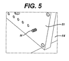
本発明の実施例は、より詳細には以下の図面を参照して説明される。図1は本発明の装置の組立体10、第1の床部12、第2の床部11を図示し、機械スイッチ13は第2の床部11に動作可能に取り付けられている。図2は、第2の床部11に取り付けられていない機械スイッチ13の組立体の全体図を示す。図3は機械スイッチ13の組み立て部品を示す。Aは近接センサー、Bはセンサーロックナット、Cはセンサーマウント、Dはフラグ、EはOリング、Fはシャフトナット、GはOリング、Hはネジ付きシャフト、Iはバネ、Jは頭部である。図4に示すように、機械スイッチは以下のように組み立てられる。まず、OリングEをシャフトナットFに嵌め、OリングGをシャフトHに嵌め、バネIを頭部Jに嵌める。図5に示すように、ネジ付きシャフトHを第2の床部11のオリフィスを通じてパッケージ14に面する表面から差し込み、反対側の表面15まで飛び出させる。図6は、差し込まれたネジ付きシャフトHおよびOリングGと共に表面14を示す。さらに、図6はオリフィス17を示し、このオリフィスはネジ付きシャフトHの挿入に使用するタイプのものである。図6はまたチャンネル18も示し、これは、空気を抜く場合に、第1の床部12と第2の床部11を密閉するOリング(図示せず)を収容するために用いられる。
Embodiments of the present invention will be described in more detail with reference to the following drawings. FIG. 1 illustrates an
この組立体を踏まえて、図7で図示されるように、OリングEを付けたシャフトナットFをシャフトHにねじ込む。フラグDをシャフトナットFの中に挿入し、フラグDのネジ付きシャフトをシャフトナットFを通じて突出させ、第2の床部の表面14上に出す。図8に示すように、頭部JはバネIと共にフラグDのネジ付きシャフトにねじ込まれる。この実施例におけるコンタクトレンズのパッケージにおいては、図9に示すように、フラグDの尾部と頭部Jの底部との間の距離は34.6mm±0.05mmとすることが重要である。センサーマウントCに潤滑油を注し、シャフトナットFを覆うように取り付ける。図10に示すように、センサーマウントCを固定するためにネジ19を締める。図11に示すように、ロックナットBをセンサーAにねじ込み、センサーAをセンサーマウントCにねじ込む。ロックナットBをセンサーマウントCに接触するまで表面15の方向にネジ締めする。図12に示すように、センサーケーブル20を専用近接センサーAの上部に取り付ける。
Based on this assembly, a shaft nut F with an O-ring E is screwed into a shaft H as shown in FIG. The flag D is inserted into the shaft nut F, and the threaded shaft of the flag D is projected through the shaft nut F and put out on the
本発明の装置を開放した図を図13に示す。圧力調節のためのポート21が第2の床部11上に示されている。また、成形されたオリフィス22(個々のパッケージを保持するために用いる)が第1の床部12に示されている。
FIG. 13 shows a view in which the apparatus of the present invention is opened. A
この装置10はコンタクトレンズの製造ラインの一部所である。これは以下のように動作する。密封されたパッケージは、第1の床部12に機械的な手段により装填される。この第2の床部11は、第1の床部12に着座するよう下方に移動する。部屋内の気圧は、ポート21を通じて空気を抜くことにより低下する。図示していないが、第2の床部11の表面14には、2つのチャネル18(Oリングのためのもの)が存在する。それぞれのチャネルは、6個の成形された凹部22を1つの圧力部屋のユニットとして収容するように、第2の床部11の周囲を取り囲んでいる。変換装置(図示せず)がある時間にわたりそれぞれの圧力部屋内の圧力を監視する。その時間内に一定の圧力がある値に達した場合、12個の機械スイッチのそれぞれからの信号が、それらが密封されているか否かを判断するために読み込まれる。密閉のスイッチはパッケージが密封されていることを意味し、開放のスイッチはリークがあることを示す。この情報は、それを表示し、記録し若しくは他の処理工程に統合する二次的な処理の部所へ伝達される。それぞれのパッケージが独自のセンサーを持つので、欠陥のあるパッケージは後工程の部所で排除される。
This
本発明は好ましい実施例を用いて説明されるが、これまでに述べた本発明の範囲および特定の形式に限定するものではなく、添付の特許請求の範囲によって述べる本発明の精神および範囲に含まれる代替物、改良物および同等物に及ぶものである。 While the invention has been described in terms of a preferred embodiment, it is not intended to be limited to the scope and specific form of the invention described above, but is encompassed by the spirit and scope of the invention as described by the appended claims. Range of alternatives, improvements and equivalents.
〔実施の態様〕
(1) 少なくとも1つの密封されたパッケージにおける漏入を検出するための装置であって、
前記パッケージは大気圧より低い気圧下にある場合に変形する蓋部を備え、
前記装置は、
前記パッケージの装填および取り出しを可能にするために開閉可能な部屋であって、閉鎖した前記部屋から空気を抜くことが可能であるか、大気圧に戻すことが可能であるかのいずれかが可能な部屋と、
頭部、尾部およびセンサーを備えた少なくとも1つの機械スイッチであって、前記部屋が大気圧で閉鎖された場合、前記頭部が前記変形可能な蓋部から第1の一定距離だけ離間して位置し、前記尾部が前記センサーから第2の一定距離だけ離間して位置する機械スイッチと、
前記機械スイッチの開閉を判断する機構と、を備える装置。
(2) 実施態様1記載の装置であって、
前記部屋が大気圧下で閉鎖される場合、前記変形可能な蓋部の表面上に前記頭部が位置する、装置。
(3) 実施態様1記載の装置であって、
複数の機械スイッチを備えた、装置。
(4) 実施態様1記載の装置であって、
前記センサーは、非接触型で容量性かつ近接型のレーザー、超音波および光学的センサーからなるグループから選択される、装置。
(5) 実施態様1記載の装置であって、
前記センサーは、非接触型で容量性の近接型センサーである、装置。
Embodiment
(1) A device for detecting leaks in at least one sealed package,
The package includes a lid that deforms when the pressure is lower than atmospheric pressure,
The device is
A room that can be opened and closed to allow loading and unloading of the package, which can either be evacuated from the closed room or returned to atmospheric pressure A nice room,
At least one mechanical switch comprising a head, a tail and a sensor, wherein the head is positioned at a first constant distance from the deformable lid when the room is closed at atmospheric pressure A mechanical switch in which the tail is located a second constant distance away from the sensor;
A mechanism for determining whether the mechanical switch is opened or closed.
(2) The apparatus according to Embodiment 1,
The apparatus, wherein the head is located on a surface of the deformable lid when the room is closed under atmospheric pressure.
(3) The apparatus according to Embodiment 1,
A device with multiple mechanical switches.
(4) The apparatus according to Embodiment 1,
The apparatus, wherein the sensor is selected from the group consisting of a non-contact, capacitive and proximity laser, ultrasonic and optical sensor.
(5) The apparatus according to Embodiment 1,
The device is a non-contact and capacitive proximity sensor.
(6) 実施態様5記載の装置であって、
前記部屋は、第1の床部および第2の床部を備え、前記第2の床部は少なくとも1つの機械スイッチを備える、装置。
(7) 実施態様6記載の装置であって、
前記第1の床部は、前記パッケージを保持するための成形された凹部を備える、装置。
(8) 実施態様1記載の装置であって、
前記パッケージは眼科用レンズのパッケージである、装置。
(9) 実施態様2記載の装置であって、
前記部屋は第1の床部および第2の床部を備え、前記第2の床部は複数の機械スイッチおよび真空ポンプを接続するためのポートを備える、装置。
(10) 実施態様1記載の装置であって、
前記第1の一定距離は、およそ0乃至30%である、装置。
(6) The apparatus according to Embodiment 5,
The apparatus, wherein the room comprises a first floor and a second floor, the second floor comprising at least one mechanical switch.
(7) The apparatus according to Embodiment 6,
The apparatus, wherein the first floor comprises a molded recess for holding the package.
(8) The apparatus according to Embodiment 1,
The apparatus, wherein the package is an ophthalmic lens package.
(9) The apparatus according to Embodiment 2,
The apparatus includes a first floor and a second floor, and the second floor includes a port for connecting a plurality of mechanical switches and a vacuum pump.
(10) The apparatus according to Embodiment 1,
The apparatus wherein the first constant distance is approximately 0-30%.
(11) 実施態様1記載の装置であって、
前記第2の一定距離は、およそ、特定の圧力で変形可能な蓋部が動く最大距離+感度範囲の80%の合計である、装置。
(12) 少なくとも1つの密封されたパッケージにおける漏入を検出するための方法であって、前記パッケージは大気圧より低い気圧下にある場合に変形する蓋部を備え、
前記方法は、
前記パッケージを前記部屋に装填する工程であって、前記部屋は、前記パッケージの装填および取り出しを可能にするために開閉可能であり、閉鎖した場合は、空気を抜くことが可能であるか、大気圧に戻すことが可能であるかのいずれかが可能であり、頭部、尾部およびセンサーを備えた少なくとも1つの機械スイッチを備え、前記部屋が大気圧で閉鎖された場合、前記頭部は前記変形可能な蓋部から第1の一定距離だけ離間して位置し、前記尾部は前記センサーから第2の一定距離だけ離間して位置する工程と、
前記部屋を閉鎖し、前記部屋内の気圧を前記パッケージおよびその内容物の内部圧力より低いレベルに低減させる工程と、
前記機械スイッチの開閉を判断する工程と、を備える方法。
(13) 実施態様12記載の方法であって、
前記パッケージはコンタクトレンズのパッケージである、方法。
(14) 実施態様12記載の方法であって、
前記気圧がおよそ−70kPa以上に減圧された、方法。
(15) 実施態様12記載の方法であって、
前記部屋が大気圧下で閉鎖される場合に、前記頭部は前記変形可能な蓋部の表面に対してバネで付勢される、方法。
(11) The apparatus according to Embodiment 1,
Said second constant distance is approximately the sum of the maximum distance that the deformable lid moves at a certain pressure plus 80% of the sensitivity range.
(12) A method for detecting leaks in at least one sealed package, the package comprising a lid that deforms when it is under atmospheric pressure,
The method
Loading the package into the room, the room being openable and closable to allow loading and unloading of the package, and when closed, can be deflated Can be returned to atmospheric pressure, comprises at least one mechanical switch with a head, tail and sensor, and when the room is closed at atmospheric pressure, the head Positioning the first lid at a first distance from the deformable lid, and positioning the tail at a second distance from the sensor;
Closing the room and reducing the air pressure in the room to a level lower than the internal pressure of the package and its contents;
Determining whether the mechanical switch is opened or closed.
(13) The method according to
The method, wherein the package is a contact lens package.
(14) A method according to
The method, wherein the atmospheric pressure is reduced to about -70 kPa or more.
(15) The method according to
The method wherein the head is spring biased against the surface of the deformable lid when the room is closed under atmospheric pressure.
(16) 実施態様12記載の方法であって、
前記方法は10秒よりも短い時間で遂行される、方法。
(17) 実施態様12記載の方法であって、
前記方法は5秒よりも短い時間で遂行される、方法。
(18) 少なくとも1つの密封されたパッケージにおける漏入を検出するための方法であって、前記パッケージは大気圧より低い気圧下にある場合に変形する蓋部を備え、
前記方法は、
前記パッケージを前記部屋に装填する工程であって、前記部屋は、前記パッケージの装填および取り出しを可能にするために開閉可能であり、閉鎖した場合は、空気を抜くことが可能であるか、大気圧に戻すことが可能であるかのいずれかが可能であり、頭部、尾部およびセンサーを備えた少なくとも1つの機械スイッチを備え、前記部屋が大気圧で閉鎖された場合、前記頭部は前記変形可能な蓋部から第1の一定距離だけ離間して位置し、前記尾部は前記センサーから第2の一定距離だけ離間して位置する工程と、
前記部屋を閉鎖し、前記部屋内の気圧を前記パッケージおよびその内容物の内部圧力より高いレベルに増加させる工程と、
前記部屋内の気圧を前記パッケージおよび前記内容物の内部圧力より低いレベルに低減させる工程と、
前記機械スイッチの開閉を判断する工程と、を備える方法。
(16) A method according to
The method is performed in less than 10 seconds.
(17) A method according to
The method is performed in less than 5 seconds.
(18) A method for detecting leaks in at least one sealed package, the package comprising a lid that deforms when it is under atmospheric pressure,
The method
Loading the package into the room, the room being openable and closable to allow loading and unloading of the package, and when closed, can be deflated Can be returned to atmospheric pressure, comprises at least one mechanical switch with a head, tail and sensor, and when the room is closed at atmospheric pressure, the head Positioning the first lid at a first distance from the deformable lid, and positioning the tail at a second distance from the sensor;
Closing the room and increasing the air pressure in the room to a level higher than the internal pressure of the package and its contents;
Reducing the air pressure in the room to a level lower than the internal pressure of the package and the contents;
Determining whether the mechanical switch is opened or closed.
Claims (18)
前記パッケージは大気圧より低い気圧下にある場合に変形する蓋部を備え、
前記装置は、
前記パッケージの装填および取り出しを可能にするために開閉可能な部屋であって、閉鎖した前記部屋から空気を抜くことが可能であるか、大気圧に戻すことが可能であるかのいずれかが可能な部屋と、
頭部、尾部およびセンサーを備えた少なくとも1つの機械スイッチであって、前記部屋が大気圧で閉鎖された場合、前記頭部が前記変形可能な蓋部から第1の一定距離だけ離間して位置し、前記尾部が前記センサーから第2の一定距離だけ離間して位置する、機械スイッチと、
前記機械スイッチの開閉を判断する機構と、を備える装置。 An apparatus for detecting leaks in at least one sealed package comprising:
The package includes a lid that deforms when the pressure is lower than atmospheric pressure,
The device is
A room that can be opened and closed to allow loading and unloading of the package, which can either be evacuated from the closed room or returned to atmospheric pressure A nice room,
At least one mechanical switch comprising a head, a tail and a sensor, wherein the head is positioned at a first constant distance from the deformable lid when the room is closed at atmospheric pressure A mechanical switch in which the tail is located a second constant distance away from the sensor;
A mechanism for determining whether the mechanical switch is opened or closed.
前記部屋が大気圧下で閉鎖される場合、前記変形可能な蓋部の表面上に前記頭部が位置する、装置。 The apparatus of claim 1, comprising:
The apparatus, wherein the head is located on a surface of the deformable lid when the room is closed under atmospheric pressure.
複数の機械スイッチを備えた、装置。 The apparatus of claim 1, comprising:
A device with multiple mechanical switches.
前記センサーは、非接触型で容量性かつ近接型のレーザー、超音波および光学的センサーからなるグループから選択される、装置。 The apparatus of claim 1, comprising:
The apparatus, wherein the sensor is selected from the group consisting of a non-contact, capacitive and proximity laser, ultrasonic and optical sensor.
前記センサーは、非接触型で容量性の近接型センサーである、装置。 The apparatus of claim 1, comprising:
The device is a non-contact and capacitive proximity sensor.
前記部屋は、第1の床部および第2の床部を備え、前記第2の床部は少なくとも1つの機械スイッチを備える、装置。 The apparatus of claim 5, comprising:
The apparatus, wherein the room comprises a first floor and a second floor, the second floor comprising at least one mechanical switch.
前記第1の床部は、前記パッケージを保持するための成形された凹部を備える、装置。 The apparatus of claim 6, comprising:
The apparatus, wherein the first floor comprises a molded recess for holding the package.
前記パッケージは眼科用レンズのパッケージである、装置。 The apparatus of claim 1, comprising:
The apparatus, wherein the package is an ophthalmic lens package.
前記部屋は第1の床部および第2の床部を備え、前記第2の床部は複数の機械スイッチおよび真空ポンプを接続するためのポートを備える、装置。 The apparatus of claim 2, comprising:
The apparatus includes a first floor and a second floor, and the second floor includes a port for connecting a plurality of mechanical switches and a vacuum pump.
前記第1の一定距離は、およそ0乃至30%である、装置。 The apparatus of claim 1, comprising:
The apparatus wherein the first constant distance is approximately 0-30%.
前記第2の一定距離は、およそ、特定の圧力で変形可能な蓋部が動く最大距離+感度範囲の80%の合計である、装置。 The apparatus of claim 1, comprising:
Said second constant distance is approximately the sum of the maximum distance that the deformable lid moves at a certain pressure plus 80% of the sensitivity range.
前記方法は、
前記パッケージを前記部屋に装填する工程であって、前記部屋は、前記パッケージの装填および取り出しを可能にするために開閉可能であり、閉鎖した場合は、空気を抜くことが可能であるか、大気圧に戻すことが可能であるかのいずれかが可能であり、頭部、尾部およびセンサーを備えた少なくとも1つの機械スイッチを備え、前記部屋が大気圧で閉鎖された場合、前記頭部は前記変形可能な蓋部から第1の一定距離だけ離間して位置し、前記尾部は前記センサーから第2の一定距離だけ離間して位置する、工程と、
前記部屋を閉鎖し、前記部屋内の気圧を前記パッケージおよびその内容物の内部圧力より低いレベルに低減させる工程と、
前記機械スイッチの開閉を判断する工程と、を備える方法。 A method for detecting leaks in at least one sealed package, the package comprising a lid that deforms when under atmospheric pressure,
The method
Loading the package into the room, the room being openable and closable to allow loading and unloading of the package, and when closed, can be deflated Can be returned to atmospheric pressure, comprises at least one mechanical switch with a head, tail and sensor, and when the room is closed at atmospheric pressure, the head A first constant distance away from the deformable lid, and the tail is located a second constant distance away from the sensor; and
Closing the room and reducing the air pressure in the room to a level lower than the internal pressure of the package and its contents;
Determining whether the mechanical switch is opened or closed.
前記パッケージはコンタクトレンズのパッケージである、方法。 The method of claim 12, comprising:
The method, wherein the package is a contact lens package.
前記気圧がおよそ−70kPa以上に減圧された、方法。 The method of claim 12, comprising:
The method, wherein the atmospheric pressure is reduced to about -70 kPa or more.
前記部屋が大気圧下で閉鎖される場合に、前記頭部は前記変形可能な蓋部の表面に対してバネで付勢される、方法。 The method of claim 12, comprising:
The method wherein the head is spring biased against the surface of the deformable lid when the room is closed under atmospheric pressure.
前記方法は10秒よりも短い時間で遂行される、方法。 The method of claim 12, comprising:
The method is performed in less than 10 seconds.
前記方法は5秒よりも短い時間で遂行される、方法。 The method of claim 12, comprising:
The method is performed in less than 5 seconds.
前記方法は、
前記パッケージを前記部屋に装填する工程であって、前記部屋は、前記パッケージの装填および取り出しを可能にするために開閉可能であり、閉鎖した場合は、空気を抜くことが可能であるか、大気圧に戻すことが可能であるかのいずれかが可能であり、頭部、尾部およびセンサーを備えた少なくとも1つの機械スイッチを備え、前記部屋が大気圧で閉鎖された場合、前記頭部は前記変形可能な蓋部から第1の一定距離だけ離間して位置し、前記尾部は前記センサーから第2の一定距離だけ離間して位置する、工程と、
前記部屋を閉鎖し、前記部屋内の気圧を前記パッケージおよびその内容物の内部圧力より高いレベルに増加させる工程と、
前記部屋内の気圧を前記パッケージおよび前記内容物の内部圧力より低いレベルに低減させる工程と、
前記機械スイッチの開閉を判断する工程と、を備える方法。
A method for detecting leaks in at least one sealed package, the package comprising a lid that deforms when under atmospheric pressure,
The method
Loading the package into the room, the room being openable and closable to allow loading and unloading of the package, and when closed, can be deflated Can be returned to atmospheric pressure, comprises at least one mechanical switch with a head, tail and sensor, and when the room is closed at atmospheric pressure, the head A first constant distance away from the deformable lid, and the tail is located a second constant distance away from the sensor; and
Closing the room and increasing the air pressure in the room to a level higher than the internal pressure of the package and its contents;
Reducing the air pressure in the room to a level lower than the internal pressure of the package and the contents;
Determining whether the mechanical switch is opened or closed.
Applications Claiming Priority (3)
| Application Number | Priority Date | Filing Date | Title |
|---|---|---|---|
| US45534203P | 2003-03-17 | 2003-03-17 | |
| PCT/US2004/008183 WO2004083800A1 (en) | 2003-03-17 | 2004-03-15 | In-line leak detector |
| US10/800,903 US20050109086A1 (en) | 2003-03-17 | 2004-03-15 | In-line leak detector |
Publications (1)
| Publication Number | Publication Date |
|---|---|
| JP2006520904A true JP2006520904A (en) | 2006-09-14 |
Family
ID=33032687
Family Applications (1)
| Application Number | Title | Priority Date | Filing Date |
|---|---|---|---|
| JP2006507284A Pending JP2006520904A (en) | 2003-03-17 | 2004-03-15 | Inline leak detector |
Country Status (8)
| Country | Link |
|---|---|
| US (1) | US20050109086A1 (en) |
| EP (1) | EP1608943A1 (en) |
| JP (1) | JP2006520904A (en) |
| KR (1) | KR20050107807A (en) |
| AU (1) | AU2004221402A1 (en) |
| BR (1) | BRPI0408400A (en) |
| CA (1) | CA2519483A1 (en) |
| WO (1) | WO2004083800A1 (en) |
Families Citing this family (4)
| Publication number | Priority date | Publication date | Assignee | Title |
|---|---|---|---|---|
| US7963163B2 (en) * | 2005-10-14 | 2011-06-21 | Johnson & Johnson Vision Care, Inc. | Systems and methods for detecting fluids |
| CN103983405B (en) * | 2014-05-29 | 2016-08-24 | 中船重工(重庆)海装风电设备有限公司 | The sealing property detecting method of floating bearing and sealing property detection device |
| CN105890847B (en) * | 2016-06-16 | 2018-04-10 | 江苏永尚能源科技有限公司 | A kind of seal leakage detection apparatus |
| ES2935309T3 (en) | 2019-10-17 | 2023-03-03 | Delta Eng Bvba | leak tester |
Family Cites Families (43)
| Publication number | Priority date | Publication date | Assignee | Title |
|---|---|---|---|---|
| US3837215A (en) * | 1973-05-21 | 1974-09-24 | T Massage | Method and apparatus for testing sealed containers |
| US4213329A (en) * | 1979-01-23 | 1980-07-22 | Benthos, Inc. | Method and apparatus for inspecting containers |
| GB2059381A (en) * | 1979-10-06 | 1981-04-23 | Danepak Ltd | Leak detecting of vacuum sealed packages |
| US4478070A (en) * | 1982-11-10 | 1984-10-23 | The Aro Corporation | Vacuum package tester and method |
| US4715215A (en) * | 1985-04-25 | 1987-12-29 | The Aro Corporation | Method and apparatus for testing the fluid-tight sealed integrity of a hermetically-sealed package in a rapidly-stabilized environment |
| US4691820A (en) * | 1985-11-18 | 1987-09-08 | Vistakon, Inc. | Package for hydrophilic contact lens |
| US4663964A (en) * | 1985-12-20 | 1987-05-12 | Warner-Lambert Company | Electronic airtightness tester |
| US4771630A (en) * | 1985-12-20 | 1988-09-20 | Warner-Lambert Company | Method and apparatus for testing hermetic seal integrity of sealed packages and containers |
| US5573108A (en) * | 1988-11-02 | 1996-11-12 | British Technology Group Ltd. | Disposable contact lens package |
| US4901558A (en) * | 1988-12-22 | 1990-02-20 | Geo A. Hormel & Co. | Seal integrity tester and method |
| US5054610A (en) * | 1989-05-31 | 1991-10-08 | Ciba-Geigy Corporation | Disposable single-use contact lens conditioning package |
| US5111684A (en) * | 1990-11-21 | 1992-05-12 | Pack Systems | Method and apparatus for leak testing packages |
| US5361626A (en) * | 1992-01-29 | 1994-11-08 | United States Surgical Corporation | Method and apparatus for detecting leaks in sealed packages |
| US5226316A (en) * | 1992-03-20 | 1993-07-13 | Oscar Mayer Foods Corporation | Package leak detection |
| DE4230025C2 (en) * | 1992-09-10 | 1995-03-09 | Jagenberg Ag | Method and device for checking the tightness of filled containers sealed with a sealed or welded-on lid |
| US5412372A (en) * | 1992-09-21 | 1995-05-02 | Medical Microsystems, Inc. | Article dispenser for monitoring dispensing times |
| NZ250453A (en) * | 1992-12-21 | 1996-12-20 | Johnson & Johnson Vision Prod | Ophthalmic lens package; planar surface with concave bowl for containing lens, sealing sheet covering bowl with lens therein |
| US5375698A (en) * | 1993-05-07 | 1994-12-27 | Allergan, Inc. | Prefilled, resealable contact lens container |
| US5337888A (en) * | 1993-09-01 | 1994-08-16 | Morrison Robert J | Contact lens case |
| US5823327A (en) * | 1993-11-02 | 1998-10-20 | Johnson & Johnson Vision Products, Inc. | Packaging arrangement for contact lenses |
| US5697495A (en) * | 1993-11-02 | 1997-12-16 | Johnson & Johnson Vision Products, Inc. | Packaging arrangement for contact lenses |
| TW295570B (en) * | 1994-05-04 | 1997-01-11 | Ciba Geigy Ag | |
| US5409104A (en) * | 1994-06-01 | 1995-04-25 | Ciba-Geigy Corporation | Contact lens package having improved access features |
| US5555504A (en) * | 1994-06-10 | 1996-09-10 | Johnson & Johnson Vision Products, Inc. | Production line tracking and quality control system |
| US5711416A (en) * | 1994-06-15 | 1998-01-27 | Bauman; Robert C. | Disposable contact lens storage container with concave storage recess |
| US5515964A (en) * | 1995-04-13 | 1996-05-14 | Bauman; Robert C. | Contact lens package with lens retaining recess |
| ES2143776T3 (en) * | 1995-08-25 | 2000-05-16 | Testamatic Ltd | METHOD AND APPARATUS FOR CHECKING FOR LEAKS IN A CONTAINER. |
| US5704468A (en) * | 1995-09-29 | 1998-01-06 | Johnson & Johnson Vision Products, Inc. | Packaging arrangement for contact lenses |
| US5577364A (en) * | 1995-11-27 | 1996-11-26 | Abbott Laboratories | On-line container and seal integrity test system |
| GB9601014D0 (en) * | 1996-01-18 | 1996-03-20 | Testamatic Ltd | Package tester |
| US5722536A (en) * | 1996-02-08 | 1998-03-03 | Bausch & Lomb Incorporated | Disposable contact lens package with snap-together feature |
| DE19622588C1 (en) * | 1996-06-05 | 1998-01-02 | Koeger Heinz | Container seal integrity testing device |
| US5695049A (en) * | 1996-10-10 | 1997-12-09 | Johnson & Johnson Vision Products, Inc. | Contact lens package with insertion feature |
| EP0791814A3 (en) * | 1997-05-26 | 1997-11-26 | Martin Lehmann | Method for leak testing and leak testing apparatus |
| EP0887282A1 (en) * | 1997-06-25 | 1998-12-30 | Wöhlk Contact-Linsen GmbH | Ready-for-sale container for the transport of contact lenses and contact lens provided for this container |
| US6401915B1 (en) * | 1997-10-14 | 2002-06-11 | Thomas Faxe | Package with an applicator for a contact lens |
| US6167751B1 (en) * | 1997-11-26 | 2001-01-02 | Thermedics Detection, Inc. | Leak analysis |
| US6330823B1 (en) * | 1998-01-13 | 2001-12-18 | Benthos, Inc. | Process and apparatus for testing containers |
| US6029808A (en) * | 1999-01-29 | 2000-02-29 | Johnson & Johnson Vision Products, Inc. | Primary package for contact lens |
| GB0001975D0 (en) * | 2000-01-29 | 2000-03-22 | Neopost Ltd | Packaging provided with means to check integrity thereof |
| US6526809B2 (en) * | 2000-03-30 | 2003-03-04 | Cincinnati Test Systems, Inc. | Method for identifying leaks in a sealed package having a liquid therein |
| US6470733B1 (en) * | 2001-08-03 | 2002-10-29 | Wayne R. Barr | Automatic testing of package content and integrity |
| US6589413B2 (en) * | 2001-08-09 | 2003-07-08 | Gould Electronics Inc. | Method of making a copper on INVAR® composite |
-
2004
- 2004-03-15 CA CA002519483A patent/CA2519483A1/en not_active Abandoned
- 2004-03-15 KR KR1020057017295A patent/KR20050107807A/en not_active Application Discontinuation
- 2004-03-15 JP JP2006507284A patent/JP2006520904A/en active Pending
- 2004-03-15 AU AU2004221402A patent/AU2004221402A1/en not_active Abandoned
- 2004-03-15 WO PCT/US2004/008183 patent/WO2004083800A1/en active Application Filing
- 2004-03-15 EP EP04757571A patent/EP1608943A1/en not_active Withdrawn
- 2004-03-15 US US10/800,903 patent/US20050109086A1/en not_active Abandoned
- 2004-03-15 BR BRPI0408400-4A patent/BRPI0408400A/en not_active IP Right Cessation
Also Published As
| Publication number | Publication date |
|---|---|
| KR20050107807A (en) | 2005-11-15 |
| US20050109086A1 (en) | 2005-05-26 |
| EP1608943A1 (en) | 2005-12-28 |
| WO2004083800A1 (en) | 2004-09-30 |
| BRPI0408400A (en) | 2006-03-21 |
| CA2519483A1 (en) | 2004-09-30 |
| AU2004221402A1 (en) | 2004-09-30 |
Similar Documents
| Publication | Publication Date | Title |
|---|---|---|
| US6330823B1 (en) | Process and apparatus for testing containers | |
| US5111684A (en) | Method and apparatus for leak testing packages | |
| US5513516A (en) | Method and apparatus for leak testing a container | |
| JP3001820B2 (en) | Container leak test method and apparatus | |
| US5105654A (en) | Method for inspecting leakage of sealed container | |
| EP0561645B1 (en) | Package leak detection | |
| US8544315B2 (en) | At rest vacuum state for vacuum decay leak testing method and system | |
| JP3093188B2 (en) | Inspection chamber and device provided with the same | |
| US7665346B1 (en) | Method and apparatus for detecting leaks in blister packs using vacuum and vision testing | |
| US6513366B1 (en) | Method and apparatus for package leak testing | |
| US6167751B1 (en) | Leak analysis | |
| EP0380863A1 (en) | Method and apparatus for detecting leaks in a sealed container | |
| JP2007530975A (en) | Inspection system for blister packaging | |
| CA2930995C (en) | Apparatus and method for the detection of leaks in a sealed container | |
| US20240077394A1 (en) | Apparatus, plant and method for inspecting flexible packages | |
| JP2006520904A (en) | Inline leak detector | |
| EP0420519A1 (en) | Hermetically sealed container and test for seal leakage thereof | |
| KR101629704B1 (en) | Leakage Test Device Using Line Laser and Leakage Test Method Thereof | |
| WO2002073151A1 (en) | Production line leak testing | |
| JP3673870B2 (en) | Hole inspection method and apparatus | |
| JPS59224536A (en) | Leak detecting method of hermetically sealed liquid enclosure | |
| JPH06278725A (en) | Inspecting device for liquid packed article | |
| NL2020599B1 (en) | Device and method for testing integrity of glove and glove port of an isolator | |
| JPH07286933A (en) | Leak inspection device | |
| EP1469296A1 (en) | Process and apparatus for checking sealor tightness of a package made of flexible or semirigid material |
Legal Events
| Date | Code | Title | Description |
|---|---|---|---|
| A621 | Written request for application examination |
Free format text: JAPANESE INTERMEDIATE CODE: A621 Effective date: 20070312 |
|
| RD04 | Notification of resignation of power of attorney |
Free format text: JAPANESE INTERMEDIATE CODE: A7424 Effective date: 20071130 |
|
| RD04 | Notification of resignation of power of attorney |
Free format text: JAPANESE INTERMEDIATE CODE: A7424 Effective date: 20080925 |
|
| A977 | Report on retrieval |
Free format text: JAPANESE INTERMEDIATE CODE: A971007 Effective date: 20090430 |
|
| A131 | Notification of reasons for refusal |
Free format text: JAPANESE INTERMEDIATE CODE: A131 Effective date: 20090512 |
|
| A601 | Written request for extension of time |
Free format text: JAPANESE INTERMEDIATE CODE: A601 Effective date: 20090812 |
|
| A602 | Written permission of extension of time |
Free format text: JAPANESE INTERMEDIATE CODE: A602 Effective date: 20090819 |
|
| A02 | Decision of refusal |
Free format text: JAPANESE INTERMEDIATE CODE: A02 Effective date: 20091117 |