JP2006208605A - Display device and directivity control element - Google Patents
Display device and directivity control element Download PDFInfo
- Publication number
- JP2006208605A JP2006208605A JP2005018842A JP2005018842A JP2006208605A JP 2006208605 A JP2006208605 A JP 2006208605A JP 2005018842 A JP2005018842 A JP 2005018842A JP 2005018842 A JP2005018842 A JP 2005018842A JP 2006208605 A JP2006208605 A JP 2006208605A
- Authority
- JP
- Japan
- Prior art keywords
- liquid crystal
- visual recognition
- display device
- viewing
- recognition area
- Prior art date
- Legal status (The legal status is an assumption and is not a legal conclusion. Google has not performed a legal analysis and makes no representation as to the accuracy of the status listed.)
- Pending
Links
Images


Landscapes
- Liquid Crystal (AREA)
- Devices For Indicating Variable Information By Combining Individual Elements (AREA)
Abstract
【課題】
簡便に一つの表示装置を異なった方向から見る観察者に、異なった表示を見せることができる表示装置及びこれに用いられる指向性制御素子を提供すること。
【解決手段】
本発明の一態様における表示装置100は、表示素子101と指向性制御素子102とを備え、電気的に制御することにより1画面表示状態と2画面表示状態とを切り替え可能である表示装置100であって、2画面表示状態において、指向性制御素子は、第1の方向から視認可能である複数の第1の視認領域と、第2の方向から視認可能である複数の第2の視認領域とを備える。第1の視認領域と第2の視認領域とは交互に繰り返し配置され、表示素子101は、第1の視認領域に対応する画像と、第1の視認領域に対応する画像と異なる第2の視認領域に対応する画像とを表示することができる。
【選択図】図1【Task】
To provide a display device that can easily show different displays to an observer who views a single display device from different directions, and a directivity control element used therefor.
[Solution]
The display device 100 according to one embodiment of the present invention includes the display element 101 and the directivity control element 102 and is a display device 100 that can be switched between a one-screen display state and a two-screen display state by electrical control. In the two-screen display state, the directivity control element includes a plurality of first visual recognition areas that are visible from the first direction and a plurality of second visual recognition areas that are visible from the second direction. Is provided. The first visual recognition area and the second visual recognition area are alternately and repeatedly arranged, and the display element 101 has a second visual recognition different from the image corresponding to the first visual recognition area and the image corresponding to the first visual recognition area. An image corresponding to the area can be displayed.
[Selection] Figure 1
Description
本発明は、見る方向により異なる画像を表示する表示装置及びこれに用いられる指向性制御素子に関する。 The present invention relates to a display device that displays different images depending on the viewing direction, and a directivity control element used therefor.
現在、表示装置は、人と機械とをつなぐインターフェースとして広く使用され、目ざましい進展を果たしている。例えば、カーナビゲーションシステムに用いられる車載用表示装置は、道路地図の表示やTV放送の受信画像の表示など、さまざまな目的に用いられる。この車載用表示装置としては、薄型・軽量・低消費電力という利点を有することから、液晶表示装置が広く用いられている。 Currently, display devices are widely used as an interface for connecting people and machines, and have made remarkable progress. For example, a vehicle-mounted display device used in a car navigation system is used for various purposes such as a road map display and a TV broadcast reception image display. As this in-vehicle display device, a liquid crystal display device is widely used because it has the advantages of being thin, light and low power consumption.
近年、カーナビゲーション技術の発展に伴い、多くの車にカーナビゲーションシステムが装備されるようになった。通常、カーナビゲーションシステムに用いられる車載用表示装置は、四輪自動車の車内前方の中央部に設けられ、運転席及び助手席から視認することができる。当該表示装置は、地図情報を表示するだけでなく、テレビ受像機としても機能し、テレビ画像やDVD画像などの映像情報を表示することもある。運転中において、運転者は地図情報を見たいが、助手席の乗員は映像情報を見たいという場合がある。したがって、運転席側からは地図情報を視認でき、一方、助手席側からは映像情報を視認できるよう、見る方向によって異なった2つの画像を表示する2画面表示を行うことが可能な表示装置の開発の要求が高まっている。 In recent years, with the development of car navigation technology, many cars have been equipped with car navigation systems. Usually, an in-vehicle display device used in a car navigation system is provided in a central portion in front of the interior of a four-wheeled vehicle and can be viewed from a driver seat and a passenger seat. The display device not only displays map information but also functions as a television receiver, and may display video information such as a television image or a DVD image. While driving, the driver may want to see the map information, but the passenger in the passenger seat may want to see the video information. Therefore, a display device capable of performing two-screen display that displays two different images depending on the viewing direction so that map information can be visually recognized from the driver's seat side and video information can be visually recognized from the passenger seat side. Development demands are increasing.
表示装置の2画面表示技術として、さまざまな手段が提案されている(例えば、非特許文献1参照。)。
非特許文献1に記載された2画面表示装置では、スキャンバックライトと高速応答液晶パネルの組み合わせにより、見る角度を変えるだけで2画面切り替え表示を可能としている。バックライトの出射方向を高速にスイッチングし、バックライトの出射方向に応じて、液晶パネルに表示させる画像を変化させる。これにより、運転席から見た場合と助手席から見た場合とで異なった画像を表示させることができる。
In the two-screen display device described in Non-Patent
しかしながら、一般に、液晶材料の粘性は低温になるにしたがって大きくなり、応答速度は遅くなってしまう。例えば、0℃以下のような低温環境下では、映像信号を駆動するタイミングに液晶パネルが追随しなくなり、正常に2画面表示ができず、2つの画像が混じり合った表示がなされる。非特許文献1に記載された2画面表示装置では、特に、液晶を高速に応答させる必要があるため、この問題は顕著となる。
However, in general, the viscosity of the liquid crystal material increases as the temperature decreases, and the response speed decreases. For example, in a low temperature environment such as 0 ° C. or less, the liquid crystal panel does not follow the timing of driving the video signal, and the two-screen display cannot be normally performed, and the display in which the two images are mixed is performed. In the two-screen display device described in Non-Patent
本発明はこのような事情を背景としてなされたものであり、本発明の目的は1画面表示と2画面表示が切り替え可能で、2画面表示状態においては、簡便に一つの表示装置を異なった方向から見る観察者に、異なった表示を見せることができる表示装置及びこれに用いられる指向性制御素子を提供することである。 The present invention has been made against the background of such circumstances, and the object of the present invention is to switch between single-screen display and dual-screen display. In the two-screen display state, one display device can be easily moved in different directions. It is to provide a display device that can show different displays to an observer who sees the camera and a directivity control element used therefor.
本発明の第1の態様にかかる表示装置は、表示素子と指向性制御素子とを備え、電気的に制御することにより1画面表示状態と2画面表示状態とを切り替え可能である表示装置であって、2画面表示状態において、前記指向性制御素子は、第1の方向から視認可能である複数の第1の視認領域と、第2の方向から視認可能である複数の第2の視認領域とを備え、前記第1の視認領域と前記第2の視認領域とは交互に繰り返し配置され、前記表示素子において前記第1の視認領域に対応する画像と前記第2の視認領域に対応する画像とが異なる画像であるものである。これによって、簡便に異なった方向から見る観察者に異なる表示を見せることができる。 A display device according to a first aspect of the present invention is a display device that includes a display element and a directivity control element and is capable of switching between a one-screen display state and a two-screen display state by electrical control. In the two-screen display state, the directivity control element includes a plurality of first visual recognition areas that are visible from the first direction and a plurality of second visual recognition areas that are visible from the second direction. The first visual recognition area and the second visual recognition area are alternately and repeatedly arranged, and the display element includes an image corresponding to the first visual recognition area and an image corresponding to the second visual recognition area. Are different images. Thereby, it is possible to easily show different displays to the observer who sees from different directions.
本発明の第2の態様にかかる表示装置は、上記の表示装置において、前記第1の視認領域と前記第2の視認領域とは略平行に配置され、前記指向性制御素子は、前記表示素子の電気的な制御の単位となるラインごとに指向性を変更することが可能であり、前記第1の視認領域及び前記第2の視認領域は、一または複数のラインを単位として形成されるものである。これによって、2画面表示状態において良好な画質を提供することが可能である。 In the display device according to a second aspect of the present invention, in the display device described above, the first visual recognition area and the second visual recognition area are arranged substantially in parallel, and the directivity control element includes the display element. The directivity can be changed for each line as a unit of electrical control, and the first visual recognition area and the second visual recognition area are formed in units of one or a plurality of lines. It is. Thereby, it is possible to provide good image quality in the two-screen display state.
本発明の第3の態様にかかる表示装置は、上記の表示装置において、前記表示素子は液晶表示素子であり、バックライトユニットをさらに備えるものである。このような構成とすることによって、従来の液晶表示装置にかかる周知技術や製造設備を利用することができ、また、汎用のバックライトユニットを使用することが可能であるため、容易に製造することが可能である。 The display device according to a third aspect of the present invention is the above display device, wherein the display element is a liquid crystal display element and further includes a backlight unit. By adopting such a configuration, it is possible to use known techniques and manufacturing equipment related to a conventional liquid crystal display device, and it is possible to use a general-purpose backlight unit, so that it can be easily manufactured. Is possible.
本発明の第4の態様にかかる表示装置は、上記の表示装置において、前記指向性制御素子は液晶素子であり、電気的に制御することにより、第1の視認領域に対応する液晶分子の立ち上がる方向と、第2の視認領域に対応する液晶分子の立ち上がる方向とが異なるものである。これによって、1画面表示状態と2画面表示状態とを簡便に切り替えることが可能である。 In the display device according to the fourth aspect of the present invention, in the above display device, the directivity control element is a liquid crystal element, and the liquid crystal molecules corresponding to the first visual recognition region rise by being electrically controlled. The direction and the direction in which the liquid crystal molecules corresponding to the second viewing region rise are different. Thereby, it is possible to easily switch between the one-screen display state and the two-screen display state.
本発明の第5の態様にかかる表示装置は、上記の表示装置において、前記第1の視認領域と前記第2の視認領域のプレチルト方向又は配向方向は、それぞれ異なるものである。プレチルト方向が異なることにより、意図的にリバースチルトを利用でき、液晶分子を2画面表示状態に適した配向方向に制御することができる。また、液晶分子の配向方向を異なる方向に制御することにより、応答速度を向上させることが可能である。 In the display device according to the fifth aspect of the present invention, in the display device described above, a pretilt direction or an orientation direction of the first viewing area and the second viewing area are different from each other. Since the pretilt direction is different, the reverse tilt can be used intentionally, and the liquid crystal molecules can be controlled in the alignment direction suitable for the two-screen display state. Further, the response speed can be improved by controlling the alignment direction of the liquid crystal molecules in different directions.
本発明の第6の態様にかかる表示装置は、上記の表示装置において、50〜120°ツイストしたツイステッドネマチック素子であるものである。これによって、視認可能である方向と視認可能方向以外でのコントラストを向上させることが可能であり、2画面表示状態における2つの異なる画像の混ざりを防止することができる。 A display device according to a sixth aspect of the present invention is a twisted nematic element twisted by 50 to 120 ° in the above display device. Thereby, it is possible to improve the contrast in the direction that is visible and the direction other than the direction in which the visual recognition is possible, and it is possible to prevent mixing of two different images in the two-screen display state.
本発明の第7の態様にかかる表示装置は、上記の表示装置において、前記指向性制御素子は、前記表示素子に対してバックライト側、または反バックライト側に配置され、前記指向性素子と前記表示素子間に偏光板を有し、前記偏光板は、前記指向性制御素子と前記表示素子に共用されているものである。このような構成において、視野角制御素子をバックライト側に配置すると、表示素子を直接視認でき自然な表示を提供することができる。一方、視野角制御素子を反バックライト側に配置することもできる。これにより、視認可能方向以外での画像の遮光率を高めることができる。また、表示素子と指向性制御素子との間の偏光板を共用することが可能であり、偏光板の吸光による光の利用効率の低下を抑制することができる。 The display device according to a seventh aspect of the present invention is the above display device, wherein the directivity control element is disposed on a backlight side or an anti-backlight side with respect to the display element, A polarizing plate is provided between the display elements, and the polarizing plate is shared by the directivity control element and the display element. In such a configuration, when the viewing angle control element is arranged on the backlight side, the display element can be directly recognized and a natural display can be provided. On the other hand, the viewing angle control element can be disposed on the side opposite to the backlight. Thereby, the light-shielding rate of the image in directions other than the visually recognizable direction can be increased. Further, it is possible to share a polarizing plate between the display element and the directivity control element, and it is possible to suppress a decrease in light use efficiency due to light absorption by the polarizing plate.
本発明の第8の態様にかかる表示装置は、上記の表示装置において、前記第1の視認領域と前記第2の視認領域との間にブラックマスクを備えるものである。このような構成とすることによって、コントラストを向上させることが可能である。また、視認方向以外への光漏れを低減でき、画像の混ざりが防止され、より高品位の2画面表示を行うことが可能である。 A display device according to an eighth aspect of the present invention is the above display device, wherein a black mask is provided between the first visual recognition area and the second visual recognition area. With such a configuration, the contrast can be improved. Further, light leakage in directions other than the viewing direction can be reduced, image mixing can be prevented, and higher-quality two-screen display can be performed.
本発明の第9の態様にかかる指向性制御素子は、表示素子と指向性制御素子とを備え、電気的に制御することにより1画面表示状態と2画面表示状態とを切り替え可能である表示装置において、2画面表示状態において、前記指向性制御素子は第1の方向から視認可能である複数の第1の視認領域と、第2の方向から視認可能である複数の第2の視認領域とを備え、前記第1の視認領域と前記第2の視認領域とは交互に繰り返し配置され、前記表示素子の前記第1の視認領域に対応する画像と、前記第1の視認領域に対応する画像とは異なる前記第2の視認領域に対応する画像とをそれぞれ異なった方向から視認可能とするものである。これによって、簡便に異なった方向から見る観察者に異なる表示を見せることができる。 A directivity control element according to a ninth aspect of the present invention includes a display element and a directivity control element, and can be switched between a one-screen display state and a two-screen display state by electrical control. In the two-screen display state, the directivity control element includes a plurality of first visual recognition areas that are visible from the first direction and a plurality of second visual recognition areas that are visible from the second direction. The first viewing area and the second viewing area are alternately and repeatedly arranged, an image corresponding to the first viewing area of the display element, and an image corresponding to the first viewing area. Is to make it possible to visually recognize images corresponding to different second viewing areas from different directions. Thereby, it is possible to easily show different displays to the observer who sees from different directions.
本発明によれば、1画面表示と2画面表示が切り替え可能で、2画面表示状態においては、簡便に一つの表示装置を異なった方向から見る観察者に、異なった表示を見せることができる表示装置及びこれに用いられる指向性制御素子を提供することが可能である。 According to the present invention, it is possible to switch between one-screen display and two-screen display, and in the two-screen display state, a display that can easily show different displays to an observer who views one display device from different directions. It is possible to provide a device and a directivity control element used therefor.
以下に、本発明を適用可能な実施の形態が説明される。以下の説明は、本発明の実施例を説明するものであり、本発明は以下の実施形態に限定されるものではない。 Hereinafter, embodiments to which the present invention can be applied will be described. The following description explains the example of the present invention, and the present invention is not limited to the following embodiment.
実施の形態1.
図1を参照して、実施の形態1にかかる表示装置について説明する。ここでは、表示装置に用いる表示素子の一例としてTN(Twisted Nematic)型のアクティブマトリクス液晶表示素子を用いた例を説明する。本実施の形態にかかる表示装置は、車載用の表示装置であり、カーナビゲーションシステムにおいて用いられる。したがって、車載用液晶表示装置(以下、液晶表示装置とする)100は、自動車の車内前方の中央部に設けられ、運転者だけでなく、助手席の乗員からも視認可能に設けられる。液晶表示装置100は、通常の1画面表示モードでは、地図情報やTVなどの映像情報のうちいずれかひとつのみを表示し、運転席側からも助手席側からも同じ情報が視認される。一方、2画面表示モードでは、液晶表示装置100は、異なる2つの視認方向に応じて、異なる2つの表示を行う。例えば、運転席側からは地図情報が視認され、助手席側からはTVなどの映像情報が視認される。
A display device according to a first exemplary embodiment will be described with reference to FIG. Here, an example in which a TN (Twisted Nematic) type active matrix liquid crystal display element is used as an example of a display element used in a display device will be described. The display device according to the present embodiment is an in-vehicle display device and is used in a car navigation system. Therefore, the in-vehicle liquid crystal display device (hereinafter, referred to as a liquid crystal display device) 100 is provided in the center of the front of the automobile, and is provided so as to be visible not only from the driver but also from the passenger in the passenger seat. In the normal one-screen display mode, the liquid
図1は、本実施の形態にかかる液晶表示装置100を説明するための模式的断面図である。液晶表示装置100は、液晶表示素子101と、指向性制御素子102と、バックライトユニット103とを備えている。図1において、上方が視認側、下方が反視認側である。バックライトユニット103の視認側には指向性制御素子102が設けられ、さらに指向性制御素子102の視認側に液晶表示素子101が配置されている。
FIG. 1 is a schematic cross-sectional view for explaining a liquid
液晶表示素子101は、1画面表示モードにおいては1つの画像表示を、2画面表示モードのおいては、後述する指向性制御素子102の視認領域に応じて、異なった2つの画像表示を行うものである。複数の画素から構成される表示領域を有する液晶表示素子101は、TFT(Thin Film Transistor)アレイ基板(不図示)と対向配置される対向基板(不図示)との間に液晶を挟持した構成を有している。TFTアレイ基板には、水平方向にゲート線(走査線)、垂直方向にソース線(信号線)がそれぞれ形成されており、ゲート線とソース線の交差点付近にはTFTが設けられている。また、ゲート線とソース線との間にマトリクス状に形成された複数の画素電極を有している。TFTのゲートがゲート線に、ソースがソース線に、ドレインが画素電極に、それぞれ接続される。
The liquid
一方、対向基板上にはコモン電極及びR(赤)、G(緑)、B(青)のカラーフィルタが形成されている。コモン電極は、実際には画素電極と対向するように対向基板の略全面に形成される透明電極である。また、TFTアレイ基板及び対向基板の内側には、ポリイミドなどからなる配向膜が形成されている。液晶分子は、配向膜の配向方向に沿って配列している。液晶分子は、TFTアレイ基板(反視認側)から対向基板(視認側)にかけて、所定の角度ねじれた状態で配列している。また、TFTアレイ基板及び対向基板の外側表面にはそれぞれ、配向方向に応じて透過軸を所定の方向に配置した偏光板(不図示)が貼着されている。 On the other hand, a common electrode and R (red), G (green), and B (blue) color filters are formed on the counter substrate. The common electrode is actually a transparent electrode formed on the substantially entire surface of the counter substrate so as to face the pixel electrode. An alignment film made of polyimide or the like is formed inside the TFT array substrate and the counter substrate. The liquid crystal molecules are arranged along the alignment direction of the alignment film. The liquid crystal molecules are arranged in a state twisted by a predetermined angle from the TFT array substrate (non-viewing side) to the counter substrate (viewing side). Further, polarizing plates (not shown) each having a transmission axis arranged in a predetermined direction according to the alignment direction are attached to the outer surfaces of the TFT array substrate and the counter substrate.
指向性制御素子102は、電気的制御により表示装置100の視認方向を制御する素子である。指向性制御素子102の構成及び機能については、後に詳述する。この指向性制御素子102には、駆動回路(不図示)よりカーナビゲーションシステムのモードに応じて電圧の供給が制御される。例えば、1画面表示モードでは、指向性制御素子102に対して電圧が供給されないため、視認方向は制御されない。また、2画面表示モードでは、指向性制御素子102に対して電圧が供給され、視認方向が制御される。このとき、指向性制御素子102は、運転席からは視認不可能であるが、助手席からは視認が可能である第1の視認領域と、助手席からは視認不可能であるが、運転席からは視認可能である第2の視認領域とを形成する。
The
バックライトユニット103は、液晶表示素子101の反視認側から液晶表示素子101に対して光を照射するものである。バックライトユニット103は、蛍光管(不図示)、導光板(不図示)などを備えた公知のものを用いることができる。なお、光源としてLED(Laser Emitting Diode)や白色有機EL(Electro Luminescence)などの他の光源を用いてもよく、光の利用効率を向上させるために、拡散シート、反射シート、プリズムシートなどの複数の光学シートを有していてもよい。
The
液晶表示素子101、指向性制御素子102及びバックライトユニット103のそれぞれの間は、接着性の樹脂によって接着し、固定するようにしてもよい。これによりそれぞれの部材界面における反射が低減され、透過率の低下を防止でき、光の利用効率を向上させることができる。
The liquid
なお、図1に示す液晶表示装置100では、指向性制御素子102を液晶表示素子101とバックライトユニット103との間に配置したが、液晶表示素子101の視認側に配置してもよい。なお、ここでは、液晶表示素子101として、TN型のアクティブマトリックス液晶表示素子を用いた例を示したが、これに限定されるものではない。例えば、他の液晶表示素子の型式として、STN(Super Twisted Nematic)型の液晶表示素子、画素電極とコモン電極が同一基板上に形成されたIPS(In Plane Switching)型の液晶表示素子などを用いることができる。本発明は、これらのような様々な型式の液晶表示素子を適用することが可能である。
In the liquid
また、有機EL素子など、液晶表示素子以外の表示素子を用いることも可能である。液晶表示素子101の代わりにCRT(Cathode Ray Tube)や有機EL素子などの自発光素子を用いる場合には、自発光素子の視認側に指向性制御素子102を配置する。
Moreover, it is also possible to use display elements other than a liquid crystal display element, such as an organic EL element. When a self-luminous element such as a CRT (Cathode Ray Tube) or an organic EL element is used instead of the liquid
ここで、上述した液晶表示装置100の駆動について説明する。TFTアレイ基板上に形成された各ゲート線には、ゲートドライバ(不図示)から走査信号が供給される。そして、各走査信号によって選択された1つのゲート線に接続されているすべてのTFTが同時にオンとなる。そして、ソースドライバ(不図示)から各ソース線に表示信号が供給され、画素電極に表示信号に応じた電荷が蓄積される。
Here, driving of the liquid
表示信号が書き込まれた画素電極とコモン電極との電位差に応じて、画素電極とコモン電極間の液晶の配列が変化する。反視認側の偏光板を透過した直線偏光は、液晶によって偏光方向が制御され、視認側偏光板を透過する光の透過率が制御される。これによって、バックライトユニット103から入射される光の透過量が制御される。液晶表示素子101の各画素は、透過する光量に応じた色の濃淡とRGBいずれかの色表示によりさまざまな色合いの表示を行う。なお、モノクロ表示の場合は、カラーフィルタを設けなくてもよい。
The arrangement of the liquid crystal between the pixel electrode and the common electrode changes in accordance with the potential difference between the pixel electrode and the common electrode where the display signal is written. The direction of polarization of the linearly polarized light that has passed through the non-viewing-side polarizing plate is controlled by the liquid crystal, and the transmittance of light transmitted through the viewing-side polarizing plate is controlled. Thereby, the transmission amount of light incident from the
次に、図2を用いて指向性制御素子102の構成について説明する。図2は指向性制御素子102の模式的断面図である。図2において上方(+Z方向)は液晶表示素子101が配置された側、すなわち視認側であり、下方(−Z方向)はバックライトユニット103が配置された側、すなわち反視認側である。また、X方向は、液晶表示装置100の左右方向であり、Y方向は上下方向である。本実施の形態においては、+X方向が運転席側とし、−X方向を助手席側とする。
Next, the configuration of the
指向性制御素子102は、一般的に広く知られているTN型の液晶素子105(以下、TN素子とする)と、第1の偏光板106と、第2の偏光板107とを備える。
TN素子105の反視認側には第1の偏光板106が、視認側には第2の偏光板107が設けられている。これら第1の偏光板106及び第2の偏光板107は、それぞれ透過軸が所定の方向に設定されている。第1の偏光板106及び第2の偏光板107として、薄型TAC(triacetylcelluloseトリアセチルセルロース)偏光板を用いても良い。
The
A first
また、指向性制御素子102の視認側には図1に示されるように液晶表示素子101が設けられている。この液晶表示素子101においても、その視認側及び反視認側の双方に偏光板を設ける必要がある。そこで、TN素子105の視認側に設けた第2の偏光板107を液晶表示素子101の反視認側に設けるべき偏光板と共用するようにしてもよい。すなわち、TN素子105と液晶表示素子101との間には、1枚の偏光板が設けられる。このような構成とすることによって、液晶表示素子101とTN素子105との間に、重複して2枚の偏光板を設けておらず、偏光板の数を減らすことができる。これによって、偏光板の吸光による透過率低下を抑制し、光の利用効率を向上させることができる。
A liquid
さらに、バックライトユニット103から出射される光が偏光性を有する場合には、バックライトユニット103に対して最も近接する偏光板(図2に示す本実施の形態においては、第1の偏光板106)を設けなくてもよい。これにより偏光板による透過率低下を低減し、光の利用効率を向上させることができる。
Further, when the light emitted from the
また、指向性制御素子102を液晶表示素子101の視認側に配置する場合、第1の偏光板106を液晶表示素子101の視認側に設けるべき偏光板と共用することができる。したがって、このような配置においても偏光板の吸光による透過率低下を防止し、光の利用効率を向上させることができる。このように、指向性制御素子102と液晶表示素子101及びバックライトユニット103との間の偏光板を共用することにより、簡易な構造となり、安価な表示素子を提供することが可能である。
Further, when the
TN素子105の第1の基板108と第2の基板109との間には、TN液晶110が挟持され、シ−ル材111によりその外周が封止されている。第1の基板108及び第2の基板109は、ガラスや透明樹脂などからなる。
A TN
第1の基板108の片面上には電極112が形成されており、第2の基板109の片面上には電極113が形成されている。第1の基板108及び第2の基板109は、電極形成面が対向するように配置されている。電極112及び電極113は、例えば、ITOなどの透明電極により形成されている。電極112と電極113との間に駆動回路(不図示)により所定の電圧を印加することによって、バックライトユニット103から指向性制御素子102に入射する光を遮光し、上述したように視認方向を制御することができる。
An
さらに電極112及び電極113上には、第1の配向膜114、第2の配向膜115がそれぞれ形成されている。第1の配向膜114及び第2の配向膜115は、TN液晶110の配向を制御するために設けられている。この第1の配向膜114、第2の配向膜115は、電極112及び電極113が形成された第1の基板108と第2の基板109の表面に、例えば、PI(ポリイミド)の有機膜を印刷し、かかる有機膜の表面にラビング処理を施すことによって、配向異方性を生じさせることにより形成される。
Further, a
また、第1の配向膜114及び第2の配向膜115は、液晶表示素子101の1ラインに対応するピッチで、1ラインごとに異なった方向にラビング処理がなされている。したがって、TN液晶110の配向方向は同じであるが、プレチルト角は1ラインごとにプラスマイナスが逆になっている。すなわち、TN液晶110の分子は1ラインごとに逆方向にわずかに立ち上がっている。このようにプレチルト角が異なることにより、意図的にリバースチルトを利用することができ、液晶分子を2画面表示時状態に適した配向に容易に制御することが可能である。また、液晶分子の配向方向が異なることによって、応答速度を向上させることができる。このようなラビング処理は、従来から広く知られているマスクラビング法などを用いて行うことが可能である。また、ラビング処理ではなく、非接触の配向法として知られている光配向法を用いて行うこともできる。
The
図3に示すように、ラビング方向の違いによって、電気的制御を行うことにより、助手席から視認可能である第1の視認領域116と、運転席から視認可能である第2の視認領域117とを形成することができる。このように、1ラインごとに交互に第1の視認領域116と第2の視認領域117とを形成することにより、それぞれの方向から視認される液晶表示素子101の画素数が少なくても良好な画質を表示することが可能である。また、容易かつ安価に表示装置を提供することができる。なお、第1の視認領域116及び第2の視認領域117は、1ラインごとに形成されていなくてもよい。例えば、数ラインごとに交互に形成されていてもよい。
As shown in FIG. 3, by performing electrical control depending on the rubbing direction, a first
このようにラビング方向を1ラインごとに変えることによって、TN液晶110の分子の立ち上がり方向を逆向きにさせることができる。このため、TN素子105に所定の電圧を供給すると、第1の視認領域116と第2の視認領域117とで、TN液晶110の分子は逆向きに立ち上がる。すなわち、簡易な駆動回路を用いて液晶分子を1画面表示状態と2画面表示状態とを簡便に切り替えることが可能である。
Thus, by changing the rubbing direction for each line, the rising direction of the molecules of the TN
液晶表示素子101において、反視認側に設けられた偏光板(不図示)の透過軸と、TN素子105の視認側に設けられた第2の偏光板107の透過軸とが異なる場合には、液晶表示素子101の偏光板と、指向性制御素子102の第2の偏光板107との間に位相差板(不図示)を配置してもよい。位相差板は、直線偏光の方向を回転させ、両偏光板の透過軸をそろえることができる。位相差板としては、例えば、λ/2波長板、ねじれ位相差板などを用いることができる。
In the liquid
また、第1の視認領域116と第2の視認領域117との間には、ブラックマスク(不図示)が形成されていることが好ましい。このような構成とすることによって、コントラストを向上させることが可能である。また、視認方向以外への光漏れを低減でき、画像の混ざりが防止され、より高品位な2画面表示を行うことが可能である。
Further, it is preferable that a black mask (not shown) is formed between the first
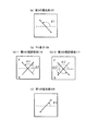
次に、図4を参照して、指向性制御素子102における各光学系の軸配置の一例について説明する。図4(a)は第2の偏光板107の吸収軸方向を示す図である。また、図4(b)はTN素子105におけるTN液晶110の配向方向、すなわち第1及び第2の配向膜114、115の配向方向を示している。そして、図4(c)は第1の偏光板106の吸収軸方向を示す図である。なお、軸角はTN素子105の中心における液晶分子長軸を基準線(図4中、点線)とし、これに対して左回りを正数としている。また、TN素子105の軸配置を示す図4(b)においてFは視認側の第2の配向膜115の配向軸を表し、Rは反視認側の第1の配向膜114の配向軸を表す。図4(b)−1中の各配向軸の矢印の方向は、第1の視認領域116における第1の配向膜114及び第2の配向膜115それぞれの配向方向を示している。また、図4(b)−2中の各配向軸の矢印の方向は、第2の視認領域117における第1の配向膜114及び第2の配向膜115それぞれの配向方向を示している。TN液晶110の分子は、各配向膜の配向方向に沿って配列し、配向膜との界面に対してチルト角を有している。すなわち、TN液晶110の分子は、配向軸の矢印の方向に向かって、配向膜の界面に対してわずかに立ち上がっている。
Next, an example of the axial arrangement of each optical system in the
図4(a)に示すように、第2の偏光板107の吸収軸角をθ1とすると、θ1は40〜45°若しくは135〜140°に設定され、より好ましくは137〜140°に設定される。
As shown in FIG. 4A, when the absorption axis angle of the second
図4(b)−1に示されるように、第1の視認領域116において、TN素子105の視認側における第2の配向膜115の配向軸の軸角をθ2とすると、θ2は120〜165°に設定され、より好ましくは、135〜145°に設定される。また、視認側の配向方向から反視認側の配向方向に至るねじれ角をφ2とすると、φ2は50〜120°に設定され、より好ましくは70〜90°に設定される。
As shown in FIG. 4B, in the
また、図4(b)−2に示されるように、第2の視認領域117において、TN素子105の視認側における第2の配向膜115の配向軸の軸角をθ2'とすると、θ2'は300〜345°に設定され、より好ましくは、315〜325°に設定される。また、視認側の配向方向から反視認側の配向方向に至るねじれ角をφ2'とすると、φ2'は50〜120°に設定され、より好ましくは70〜90°に設定される。
Further, as shown in FIG. 4B-2, when the axial angle of the orientation axis of the
また、液晶分子の屈折率異方性(測定光波長589nm、以下同じ)Δn2と液晶層の厚みd2の積であるリタデ−ション値Δn2・d2は、第1の範囲0.3〜0.5μm、第2の範囲0.9〜1.3μm又は第3の範囲1.3〜1.9μmのいずれかに設定され、より好ましくは第2の範囲0.9〜1.3μmに設定される。リタデーション値は、第1から第3の範囲のいずれでも制御は可能であるが、視認方向への透過率と非視認方向への遮光性から第2または第3の範囲が好ましく、制御のしやすさなどのバランスを考慮すると、第2の範囲とすることがもっとも好ましい。 The retardation value Δn2 · d2 which is the product of the refractive index anisotropy of the liquid crystal molecules (measurement light wavelength 589 nm, hereinafter the same) Δn2 and the thickness d2 of the liquid crystal layer is in the first range 0.3 to 0.5 μm. The second range is set to 0.9 to 1.3 μm or the third range is set to 1.3 to 1.9 μm, and more preferably the second range is set to 0.9 to 1.3 μm. The retardation value can be controlled in any of the first to third ranges, but the second or third range is preferable from the viewpoint of the transmittance in the viewing direction and the light shielding property in the non-viewing direction, and is easy to control. In consideration of a balance such as the above, the second range is most preferable.
図4(c)に示されるように、第1の偏光板106の軸角をθ3とすると、θ3は135〜140°若しくは40〜45°に設定され、より好ましくは40〜43°に設定される。視認方向への透過率と非視認方向への遮光性を両立でき、指向性制御素子の性能が向上するためである。
As shown in FIG. 4C, when the axial angle of the first
通常のTN素子における偏光板の吸収軸の交差角は90°であるが、斜め方向から見ると交差角が実効的に90°以上になる。これが光漏れの要因となるため、第1の偏光板106及び第2の偏光板107の吸収軸の交差角を90°未満に設定する。このような構成とすることによって、左右方向(±X方向)からの遮光度を改善することができる。特に、第1及び第2の偏光板106、107の吸収軸の交差角は、80°〜86°であることが好ましい。
The crossing angle of the absorption axes of the polarizing plates in a normal TN device is 90 °, but when viewed from an oblique direction, the crossing angle is effectively 90 ° or more. Since this causes light leakage, the crossing angle of the absorption axes of the first
ここで、図5を参照して、2画面表示モード(TN素子105に所定の電圧を供給している状態)におけるTN液晶110の分子の配列について説明する。図5は、TN液晶110の分子(以下、TN液晶分子118とする)の長軸方向を説明するための概略図である。ここでは、TN素子105の厚み(Z方向)中央近傍におけるTN液晶分子118について図示している。図5(a)は第1の視認領域116におけるTN液晶分子118の長軸方向を示しており、図5(b)は第2の視認領域117におけるTN液晶分子118の長軸方向を示している。本実施の形態にかかるTN液晶分子118は、図5に示すように、一般的に知られている棒状の細長い分子である。ここで、TN素子105の法線方向とは、光の出射面に対する法線方向であり、図5におけるZ方向である。
Here, with reference to FIG. 5, the arrangement of molecules of the TN
上述したように、第1の視認領域116と、第2の視認領域117とで、TN液晶分子118は、立ち上がる方向が異なる。すなわち、第1の視認領域116においては、TN液晶分子118の長軸方向は、+X方向に向かって法線方向からθ4だけ傾いた状態で配列している。一方、第2の視認領域117においては、TN液晶分子118の長軸方向は、−X方向に向かって法線方向からθ4だけ傾いた状態で配列している。また、TN素子105の厚み(Z方向)中央近傍におけるTN液晶分子118の長軸方向は、X方向に平行であることが好ましい。
As described above, the rising direction of the TN
第1の視認領域116においては、TN液晶分子118の長軸方向とTN素子105の法線方向とがなす角が+X方向にθ4以上の方向(この場合、運転席から液晶表示装置100を視認する方向)から液晶表示装置100を視認すると、液晶の複屈折性により、位相遅延が増加し、透過率が低くなる。TN液晶分子118の長軸方向から観察した場合の液晶の屈折率が最も小さく、それよりも−X方向側では再び屈折率が大きくなるため、一般的によく知られている階調反転現象が起こる。つまり、液晶表示装置100を+X方向側の一定の角度θ4以上から視認すると、白階調は黒階調に反転する。一方、TN液晶分子118の長軸方向とTN素子105の法線方向とがなす角が−X方向にθ4以上(この場合、助手席から液晶表示装置100を視認する方向)から液晶表示装置100を視認すると、位相遅延の増加はほとんどなく、透過率は変化しない。
In the
第2の視認領域117においては、TN液晶分子118の長軸方向とTN素子105の法線方向とがなす角が−X方向にθ4以上(この場合、助手席から液晶表示装置100を視認する方向)から液晶表示装置100を視認すると、液晶の複屈折性により、位相遅延が増加し、透過率が低くなる。TN液晶分子118の長軸方向から観察した場合の液晶の屈折率が最も小さく、それよりも−X方向側では再び屈折率が大きくなるため、一般的によく知られているTN素子の階調反転現象が起こる。つまり、液晶表示装置100を−X方向側の一定の角度θ4(視野角制御方向)以上から視認すると、白階調は黒階調に反転する。一方、TN液晶分子118の長軸方向とTN素子105の法線方向とがなす角が+X方向にθ4以上(この場合、運転席から液晶表示装置100を視認する方向)から液晶表示装置100を視認すると、位相遅延の増加はほとんどなく、透過率は変化しない。
In the
液晶表示素子101は、上述したように、第1の視認領域116に対応して映像情報の表示を、第2の視認領域117に対応して地図情報の表示をそれぞれ行う。したがって、上述の指向性制御素子102と組み合わせることによって、第1の視認領域116は、助手席から見ると第1の視認領域116に対応した映像情報が視認可能であり、運転席から見ると遮光され当該映像情報は視認不可能である。また、第2の視認領域117は、運転席から見ると第2の視認領域117に対応した地図情報が視認可能であり、一方、助手席から見ると遮光され当該地図情報は視認不可能である。このように、見る方向によって異なる2つの画像を表示することができる。
As described above, the liquid
このように、TN素子を用いることによって、運転席からは視認不可能であるが、助手席からは視認が可能である第1の視認領域と、助手席からは視認不可能であるが、運転席からは視認可能である第2の視認領域とのコントラストを向上させることができ、画像の混ざりを防止することが可能である。また、容易かつ安価に表示装置を製造することが可能である。 As described above, by using the TN element, it is not visible from the driver's seat, but is visible from the passenger seat and not visible from the passenger seat. The contrast with the second viewing area that can be seen from the seat can be improved, and mixing of images can be prevented. In addition, a display device can be easily and inexpensively manufactured.
また、液晶表示素子101は、1ラインごとに運転席側と助手席側の映像を表示しているので、輝度の低下を抑制し、効率よく光を利用することができ、良好な表示を行うことが可能である。
In addition, since the liquid
さらに、液晶表示素子101及び指向性制御素子102の液晶分子を高速に応答させる必要がないため、様々な外部環境、例えば0度以下のような低温環境下においても安定した表示を行うことが可能である。
Further, since it is not necessary to cause the liquid crystal molecules of the liquid
図5において、TN液晶分子118の長軸方向とTN素子105の法線方向とがなす角θ4は、30°以内であることが好ましい。このような配列とすることによって、さらに第1の視認領域116においては運転席側の、第2の視認領域117においては助手席側の遮光を行うことが可能である。
In FIG. 5, the angle θ4 formed by the major axis direction of the TN
本発明においては、TN素子105に所定の電圧を印加した状態において、少なくともTN素子105の厚み中央におけるTN液晶分子118の長軸方向が、TN素子105の法線方向から傾いて配列していればよい。すなわち、図4においては、TN液晶110は50〜120°ねじれた配列としたが、ねじれていなくてもよい。つまり、TN液晶110のねじれ角が0°であってもよい。
In the present invention, in a state where a predetermined voltage is applied to the
また、ここでは、正の屈折率異方性を有するネマチック液晶を例として説明したが、
負の屈折率異方性をもつディスコチック液晶などさまざまなタイプの液晶を用いることも可能である。
In addition, here, a nematic liquid crystal having a positive refractive index anisotropy has been described as an example.
Various types of liquid crystal such as discotic liquid crystal having negative refractive index anisotropy can also be used.
実施の形態2.
次に、実施の形態2にかかる液晶表示装置について説明する。本実施の形態にかかる液晶表示装置は、実施の形態1において説明した液晶表示装置100と同様の構成を有している。本実施の形態において、実施の形態1と異なる点は、TN液晶分子118の立ち上がり方向の制御に、斜め電界を用いた点である。
Next, a liquid crystal display device according to
図6は、実施の形態2にかかるTN素子105の2画面表示モード(TN素子105に所定の電圧を供給している状態)における液晶分子の配列を概略的に示している。図6において、図2と同一の構成要素には、同一の符号を付し、説明を省略する。ここでは、TN素子105の厚み(Z方向)中央近傍におけるTN液晶分子118について図示している。図6(a)は第1の視認領域116におけるTN液晶分子118の長軸方向を示しており、図6(b)は第2の視認領域117におけるTN液晶分子118の長軸方向を示している。本実施の形態にかかるTN液晶分子118は、図6に示すように、一般的に知られている棒状の細長い分子である。ここで、TN素子105の法線方向とは、光の出射面に対する法線方向であり、図6におけるZ方向である。
FIG. 6 schematically shows an arrangement of liquid crystal molecules in the two-screen display mode (a state where a predetermined voltage is supplied to the TN element 105) of the
本実施の形態においては、1ラインごとに、2枚の基板108、109に形成される電極112及び電極113の設けられている位置がずれている。すなわち、TN液晶110に対して斜めに電界がかかる斜め電界を用いる。したがって、第1の視認領域116に対応する電極112は−X方向に、電極113は+X方向にずれるように形成される。一方、第2の視認領域に対応する電極112は+X方向に、電極113は−X方向にずれるように形成される。
In this embodiment, the positions where the
したがって、上記のように形成した上下の電極に電圧を印加すると、第1の視認領域116においては、電界方向は法線方向から+X方向に傾いた方向となる。また、第2の視認領域117においては、電界方向は法線方向から−X方向に傾いた方向となる。通常よく知られているように、正の誘電率異方性を有する液晶分子はその長軸が、電界方向に沿って配列する。このため、2画面表示モードにおいて第1の視認領域116では、図6(a)に示すように、TN液晶分子118の長軸方向は、法線方向から+X方向に傾いた状態で配列する。一方、第2の視認領域117では、図6(b)に示すように、法線方向から−X方向に傾いた状態で配列する。
Therefore, when a voltage is applied to the upper and lower electrodes formed as described above, the electric field direction is inclined in the + X direction from the normal direction in the
斜め電界によって、TN液晶分子118が立ち上がる方向を制御可能とするため、TN素子105の厚み方向の中心のTN液晶分子118が、第1の基板108及び第2の基板109に対して平行に配向していることが好ましい。したがって、図6に示すように、TN液晶分子118をスプレイ配向とすることが好ましい。TN液晶分子118の傾きは、上下の電極112及び113に印加する電圧を制御することにより、調整することが可能である。
In order to control the rising direction of the TN
このように、斜め電界を用いることによって、実施の形態1と同様に、第1の視認領域116においては、TN液晶分子118の長軸方向とTN素子105の法線方向とがなす角が+X方向にθ4以上の方向(この場合、運転席から液晶表示装置100を視認する方向)からは、液晶表示装置100の表示が視認不可能となる。一方、第2の視認領域117においては、TN液晶分子118の長軸方向とTN素子105の法線方向とがなす角が−X方向にθ4以上(この場合、助手席から液晶表示装置100を視認する方向)からは、液晶表示装置100の表示が視認不可能となる。
As described above, by using the oblique electric field, the angle formed by the major axis direction of the TN
液晶表示素子101は、上述したように、第1の視認領域116に対応して映像情報の表示を、第2の視認領域117に対応して地図情報の表示をそれぞれ行う。したがって、上述の指向性制御素子102と組み合わせることによって、第1の視認領域116は、助手席から見ると第1の視認領域116に対応した映像情報が視認可能であり、運転席から見ると遮光され当該映像情報は視認不可能である。また、第2の視認領域117は、運転席から見ると第2の視認領域に対応した地図情報が視認可能であり、一方、助手席から見ると遮光され当該地図情報は視認不可能である。
As described above, the liquid
また、1ラインごとに運転席側と助手席側の映像を表示しているので、輝度の低下を抑制し、効率よく光を利用でき、良好な表示を行うことが可能である。 Further, since the images on the driver's seat side and the passenger seat side are displayed for each line, it is possible to suppress a decrease in luminance, efficiently use light, and perform good display.
図5において、TN液晶分子118の長軸方向とTN素子105の法線方向とがなす角θ4は、30°以内であることが好ましい。このような配列とすることによって、さらに第1の視認領域116においては運転席側の、第2の視認領域117においては助手席側の遮光を行うことが可能である。
In FIG. 5, the angle θ4 formed by the major axis direction of the TN
また、本実施の形態の場合、実施の形態1において説明したように、ラビング方向を変えることは、不要である。電界の方向によって、TN液晶分子118の立ち上がり方向を、制御することが可能ためである。
In the case of the present embodiment, as described in the first embodiment, it is not necessary to change the rubbing direction. This is because the rising direction of the TN
なお、車載用液晶表示装置を例として説明したが、本発明はこれに限定されるものではない。例えば、携帯電話などにおいて異なる方向から異なる表示を行う場合など、さまざまな表示装置に適用することが可能である。 The on-vehicle liquid crystal display device has been described as an example, but the present invention is not limited to this. For example, the present invention can be applied to various display devices, such as when performing different display from different directions on a mobile phone or the like.
100 車載用液晶表示装置
101 液晶表示素子
102 指向性制御素子
103 バックライトユニット
105 TN素子
106 第1の偏光板
107 第2の偏光板
108 第1の基板
109 第2の基板
110 TN液晶
111 シール材
112 電極
113 電極
114 第1の配向膜
115 第2の配向膜
116 第1の視認領域
117 第2の視認領域
118 TN液晶分子
DESCRIPTION OF
Claims (9)
2画面表示状態において、前記指向性制御素子は、第1の方向から視認可能である複数の第1の視認領域と、第2の方向から視認可能である複数の第2の視認領域とを備え、
前記第1の視認領域と前記第2の視認領域とは交互に繰り返し配置され、
前記表示素子の前記第1の視認領域に対応する画像と前記第2の視認領域に対応する画像とが異なる画像である表示装置。 A display device comprising a display element and a directivity control element and capable of switching between a one-screen display state and a two-screen display state by electrical control,
In the two-screen display state, the directivity control element includes a plurality of first visual recognition areas that are visible from the first direction and a plurality of second visual recognition areas that are visible from the second direction. ,
The first visual recognition area and the second visual recognition area are alternately and repeatedly arranged,
A display device in which an image corresponding to the first viewing area of the display element is different from an image corresponding to the second viewing area.
前記指向性制御素子は、前記表示素子の電気的な制御の単位となるラインごとに指向性を変更することが可能であり、
前記第1の視認領域及び前記第2の視認領域は、一または複数のラインを単位として形成される請求項1に記載の表示装置。 The first viewing area and the second viewing area are arranged substantially in parallel,
The directivity control element can change the directivity for each line that is a unit of electrical control of the display element,
The display device according to claim 1, wherein the first visual recognition area and the second visual recognition area are formed in units of one or a plurality of lines.
バックライトユニットをさらに備える請求項1又は2に記載の表示装置。 The display element is a liquid crystal display element;
The display device according to claim 1, further comprising a backlight unit.
前記指向性素子と前記表示素子間に偏光板を有し、
前記偏光板は、前記指向性制御素子と前記表示素子に共用されている請求項3〜6のいずれか1項に記載の表示装置。 The directivity control element is disposed on the backlight side or the anti-backlight side with respect to the display element,
Having a polarizing plate between the directional element and the display element;
The display device according to claim 3, wherein the polarizing plate is shared by the directivity control element and the display element.
2画面表示状態において、前記指向性制御素子は第1の方向から視認可能である複数の第1の視認領域と、第2の方向から視認可能である複数の第2の視認領域とを備え、
前記第1の視認領域と前記第2の視認領域とは交互に繰り返し配置され、
前記表示素子の前記第1の視認領域に対応する画像と、前記第1の視認領域に対応する画像とは異なる前記第2の視認領域に対応する画像とをそれぞれ異なった方向から視認可能とする指向性制御素子。 In a display device that includes a display element and a directivity control element and can be switched between a one-screen display state and a two-screen display state by electrical control.
In the two-screen display state, the directivity control element includes a plurality of first viewing areas that are visible from the first direction and a plurality of second viewing areas that are visible from the second direction.
The first visual recognition area and the second visual recognition area are alternately and repeatedly arranged,
An image corresponding to the first visual recognition area of the display element and an image corresponding to the second visual recognition area different from the image corresponding to the first visual recognition area can be viewed from different directions. Directional control element.
Priority Applications (1)
| Application Number | Priority Date | Filing Date | Title |
|---|---|---|---|
| JP2005018842A JP2006208605A (en) | 2005-01-26 | 2005-01-26 | Display device and directivity control element |
Applications Claiming Priority (1)
| Application Number | Priority Date | Filing Date | Title |
|---|---|---|---|
| JP2005018842A JP2006208605A (en) | 2005-01-26 | 2005-01-26 | Display device and directivity control element |
Publications (1)
| Publication Number | Publication Date |
|---|---|
| JP2006208605A true JP2006208605A (en) | 2006-08-10 |
Family
ID=36965558
Family Applications (1)
| Application Number | Title | Priority Date | Filing Date |
|---|---|---|---|
| JP2005018842A Pending JP2006208605A (en) | 2005-01-26 | 2005-01-26 | Display device and directivity control element |
Country Status (1)
| Country | Link |
|---|---|
| JP (1) | JP2006208605A (en) |
Cited By (3)
| Publication number | Priority date | Publication date | Assignee | Title |
|---|---|---|---|---|
| JP2009053345A (en) * | 2007-08-24 | 2009-03-12 | Toshiba Corp | Directive backlight, display device and stereoscopic image display device |
| JP2012181544A (en) * | 2012-05-10 | 2012-09-20 | Toshiba Corp | Stereoscopic image display device and control device |
| JP2020118965A (en) * | 2019-01-18 | 2020-08-06 | 中強光電股▲ふん▼有限公司 | Display device and light source module of the same |
-
2005
- 2005-01-26 JP JP2005018842A patent/JP2006208605A/en active Pending
Cited By (3)
| Publication number | Priority date | Publication date | Assignee | Title |
|---|---|---|---|---|
| JP2009053345A (en) * | 2007-08-24 | 2009-03-12 | Toshiba Corp | Directive backlight, display device and stereoscopic image display device |
| JP2012181544A (en) * | 2012-05-10 | 2012-09-20 | Toshiba Corp | Stereoscopic image display device and control device |
| JP2020118965A (en) * | 2019-01-18 | 2020-08-06 | 中強光電股▲ふん▼有限公司 | Display device and light source module of the same |
Similar Documents
| Publication | Publication Date | Title |
|---|---|---|
| CN100437278C (en) | Display | |
| JP5301605B2 (en) | Liquid crystal display | |
| CN102067020B (en) | Liquid crystal display panel and liquid crystal display device | |
| US20050286000A1 (en) | Adjustable-viewing-angle liquid crystal display | |
| US20180299726A1 (en) | Display device | |
| KR20110081069A (en) | Liquid crystal display | |
| US9013657B2 (en) | Liquid crystal device, electronic device and projector with maximum-light-intensity direction inclined from the direction normal to the substrates | |
| US8300190B2 (en) | Liquid crystal panel, liquid crystal display unit, and television receiver equipped with the same | |
| JP4152912B2 (en) | Dual LCD using a dual front light unit | |
| US8054242B2 (en) | Liquid crystal display device and method of driving the same | |
| KR20090058992A (en) | Multi-Visual Display | |
| US7898602B2 (en) | Display apparatus | |
| US9304343B2 (en) | Liquid crystal display device | |
| JP2007171674A (en) | Transflective liquid crystal display device and portable terminal device | |
| JP2006195388A (en) | Viewing angle control display device and viewing angle control element | |
| JP2006208606A (en) | In-vehicle display device | |
| JP2008090173A (en) | Display device | |
| JP2015052624A (en) | Stereoscopic display device | |
| US10866441B2 (en) | Liquid crystal display device | |
| US7868980B2 (en) | Display apparatus | |
| JP4649149B2 (en) | Liquid crystal display device | |
| JP2006208605A (en) | Display device and directivity control element | |
| CN118192109A (en) | Liquid crystal display device with local viewing angle adjustment function | |
| JP2010032787A (en) | Liquid crystal display | |
| JP2006209021A (en) | Display device and viewing angle control element |