JP2006046570A - Ball circulation member and ball screw - Google Patents
Ball circulation member and ball screw Download PDFInfo
- Publication number
- JP2006046570A JP2006046570A JP2004230730A JP2004230730A JP2006046570A JP 2006046570 A JP2006046570 A JP 2006046570A JP 2004230730 A JP2004230730 A JP 2004230730A JP 2004230730 A JP2004230730 A JP 2004230730A JP 2006046570 A JP2006046570 A JP 2006046570A
- Authority
- JP
- Japan
- Prior art keywords
- ball
- scooping
- side cap
- circulation member
- base end
- Prior art date
- Legal status (The legal status is an assumption and is not a legal conclusion. Google has not performed a legal analysis and makes no representation as to the accuracy of the status listed.)
- Granted
Links
- 230000002093 peripheral effect Effects 0.000 claims description 34
- 238000005096 rolling process Methods 0.000 claims description 31
- 239000000470 constituent Substances 0.000 claims description 21
- 230000000452 restraining effect Effects 0.000 description 9
- 239000011347 resin Substances 0.000 description 6
- 229920005989 resin Polymers 0.000 description 6
- 230000000694 effects Effects 0.000 description 4
- 238000000465 moulding Methods 0.000 description 4
- 230000001154 acute effect Effects 0.000 description 3
- 230000000052 comparative effect Effects 0.000 description 3
- 206010016256 fatigue Diseases 0.000 description 3
- 230000013011 mating Effects 0.000 description 3
- 238000004891 communication Methods 0.000 description 2
- 230000006378 damage Effects 0.000 description 2
- 239000000463 material Substances 0.000 description 2
- 230000008878 coupling Effects 0.000 description 1
- 238000010168 coupling process Methods 0.000 description 1
- 238000005859 coupling reaction Methods 0.000 description 1
- 238000001746 injection moulding Methods 0.000 description 1
- 239000002184 metal Substances 0.000 description 1
- 230000011218 segmentation Effects 0.000 description 1
- 230000009466 transformation Effects 0.000 description 1
Images


Classifications
-
- F—MECHANICAL ENGINEERING; LIGHTING; HEATING; WEAPONS; BLASTING
- F16—ENGINEERING ELEMENTS AND UNITS; GENERAL MEASURES FOR PRODUCING AND MAINTAINING EFFECTIVE FUNCTIONING OF MACHINES OR INSTALLATIONS; THERMAL INSULATION IN GENERAL
- F16H—GEARING
- F16H25/00—Gearings comprising primarily only cams, cam-followers and screw-and-nut mechanisms
- F16H25/18—Gearings comprising primarily only cams, cam-followers and screw-and-nut mechanisms for conveying or interconverting oscillating or reciprocating motions
- F16H25/20—Screw mechanisms
- F16H25/22—Screw mechanisms with balls, rollers, or similar members between the co-operating parts; Elements essential to the use of such members
- F16H25/2204—Screw mechanisms with balls, rollers, or similar members between the co-operating parts; Elements essential to the use of such members with balls
- F16H25/2214—Screw mechanisms with balls, rollers, or similar members between the co-operating parts; Elements essential to the use of such members with balls with elements for guiding the circulating balls
Landscapes
- Engineering & Computer Science (AREA)
- General Engineering & Computer Science (AREA)
- Mechanical Engineering (AREA)
- Transmission Devices (AREA)
Abstract
Description
本発明は、各種産業機械等に用いられるボールねじに関する。 The present invention relates to a ball screw used in various industrial machines.
この種のボールねじは、例えば、図10に示すボールねじ100のように、外周面に螺旋状のボール転動溝を有して軸方向に延びるねじ軸12を有している。そして、そのねじ軸12のボール転動溝に対応する螺旋状のボール転動溝を内周面に有するナット14がねじ軸12に嵌合している。ここで、ナット14のボール転動溝とねじ軸12のボール転動溝とは互いに対向して両者の間にボール軌道路8を構成しており、そのボール軌道路8には、転動体としての複数のボール15が転動可能に装填される。
This type of ball screw has, for example, a
近年、この種のボールねじでは、ボールを循環させるボール循環部材として、ボールの円滑な循環を確保するために、つまり、螺旋状のボール軌道路を転がるボールをボール循環部材内に円滑に導き、且つボール循環部材内を移動するボールをボール軌道路に円滑に戻すために、ボール軌道路の接線方向にボールを掬い上げ、且つボール軌道路の接線方向からボール軌道路内にボールを戻すことが多くなってきた(例えば特許文献1参照)。 In recent years, in this kind of ball screw, as a ball circulation member for circulating the ball, in order to ensure a smooth circulation of the ball, that is, the ball rolling on the spiral ball raceway is smoothly guided into the ball circulation member, In addition, in order to smoothly return the ball moving in the ball circulation member to the ball track, the ball can be picked up in the tangential direction of the ball track and returned to the ball track from the tangential direction of the ball track. It has increased (see, for example, Patent Document 1).
例えば、この種のボールねじでは、図10に示すように、ナット14には、その外周面に平坦面からなるボール循環部材取付け面16が形成される。そして、そのボール循環部材取付け面16に、二個一組の長孔20が形成され、この長孔20が上記ボール軌道路8に連通して穿孔される。そして、このボール循環部材取付け面16に、ボール循環部材170が取り付けられる(例えば特許文献2参照)。
ここで、ボール循環部材170には、図10に示すように、ボール循環部材170の中央部の両側に一対の脚部190が設けられる。この一対の脚部190は、例えば図11に示すように、ねじ軸12のリード角に対応するように、ボール循環部材170中央部に対して互いに異なる方向に所定角度傾けられて形成されている。そして、その一対の脚部190を、上記ボール循環部材取付け面16に形成された長孔20に、ねじ軸12に対して垂直方向から、ほとんど隙間なく嵌め込み可能になっている。
Here, as shown in FIG. 10, the
ここで、この種のボール循環部材170は、例えば樹脂成形により製作されており、図11に示すように、一対のボール循環部材構成部材230,230を組み合わせて構成される。すなわち、ボール循環部材170は、ボール15を循環させる通路となるボール循環通路がボール循環部材170の内側に形成されて、その内部を通るボール15の進行方向に延びる分割線に沿って二つに分割された一対のサイドキャップ構成部材230,230として構成される。ここで、同図に符号PL’で示す線は、ボール循環部材170を、各サイドキャップ構成部材230に分割する分割線を示している。
Here, this type of
ところで、この分割線PL’を設定する位置は、ボール15の中心の軌跡に合わせて設定することが考えられる。すなわち、分割線PL’をこのような位置に設定してボール循環部材170を一対のサイドキャップ構成部材230,230に分割すれば、ボール循環部材構成部材230のそれぞれは、ボール15に対して、ほぼ同等にボール15の周囲を取り囲んで形成されるから、ボール15を拘束する性能を安定させる上では、好ましい分割位置であると考えられるからである。
By the way, it is conceivable that the position for setting the dividing line PL ′ is set in accordance with the locus of the center of the
しかし、ボール循環部材170には、通常、例えば図12に示すように、ボール循環部材170のボール掬い上げ(戻し)通路210の先端部分に、ボール掬い上げ部240を有している。ここで、ボール掬い上げ部240は、上記ボール軌道路8内を転動するボール15を、ボール軌道路8からボール掬い上げ(戻し)通路210へ掬い上げるために、ねじ軸12のボール転動溝に挿入可能な舌状の形状をしており、ボール転動溝に向けてボール掬い上げ(戻し)通路210から突出して形成される。そのため、ボール掬い上げ部240とボール掬い上げ(戻し)通路210とが繋がる部分となる掬い上げ基端部240aには、切欠き部25が、例えば鋭角をなすV字状の溝部として形成されることになる。
However, the
したがって、分割線PL’を、図12に示すように、ボール循環部材170全体に渡ってボール中心の軌跡(同図に示す符号BCDで示す線)に合わせて設定した場合、切欠き部25は、例えば図13に示すように、掬い上げ基端部240aの側にそのまま残されてしまうことになる(同図に示すF’部分参照)。
すなわち、掬い上げ基端部240での分割線PL’を、単に、このような位置に設定した場合は、ボールねじ100の高速回転時等でボール掬い上げ部240に繰り返し荷重が負荷されると、その掬い上げ基端部240aでの切欠き部250が、応力集中により破損の基点となり、高速化を妨げる原因になるおそれがある。
本発明は、このような問題点に着目してなされたものであって、ボール循環部材において、強度が弱い掬い上げ基端部での強度を改善することにより、高速運転性能や耐久性能を向上させ得るボール循環部材およびボールねじを提供することを目的としている。
Therefore, when the dividing line PL ′ is set in accordance with the trajectory of the center of the ball over the entire ball circulation member 170 (a line indicated by the symbol BCD shown in FIG. 12) as shown in FIG. For example, as shown in FIG. 13, it is left as it is on the side of the scooping
That is, when the dividing line PL ′ at the scooping
The present invention has been made paying attention to such problems, and improves the high-speed driving performance and durability performance by improving the strength at the base end of the ball circulating member, which is weak in strength. It is an object of the present invention to provide a ball circulation member and a ball screw that can be made to exist.
上記課題を解決するために、請求項1に記載の発明は、外周面にボール転動溝を有するねじ軸と、該ねじ軸の外周面と対向する内周面にボール転動溝を有するナットと、前記ナットおよびねじ軸の両ボール転動溝間で構成するボール軌道路に配設された複数のボールと、を備えるボールねじに用いられ、前記ボール軌道路内のボールを一方の側から掬い上げるボール掬い上げ部と、該ボール掬い上げ部で掬い上げたボールを他方の側から前記ボール軌道路内へ戻すボール循環通路と、を一体に有し、当該一体に有するボール掬い上げ部とボール循環通路とが繋がる部分である掬い上げ基端部に切欠き部をもつボール循環部材であって、前記ボール循環部材は、その内部を通る前記ボールの進行方向に延びる分割線に沿って分割された二つのボール循環部材構成部材を備えて構成されてなり、前記分割線は、前記一方の側での前記切欠き部の最も深い部分と前記他方の側での前記切欠き部の最も深い部分とを通ることを特徴としている。 In order to solve the above problems, the invention according to claim 1 is a screw shaft having a ball rolling groove on an outer peripheral surface, and a nut having a ball rolling groove on an inner peripheral surface facing the outer peripheral surface of the screw shaft. And a plurality of balls disposed in a ball raceway formed between both ball rolling grooves of the nut and the screw shaft, and the ball in the ball raceway is moved from one side. A ball scooping part that scoops up the ball, and a ball circulation passage that returns the ball scooped up by the ball scooping part from the other side into the ball raceway, A ball circulation member having a notch at a scooping base end which is a portion connected to a ball circulation passage, wherein the ball circulation member is divided along a dividing line extending in a traveling direction of the ball passing through the inside. Two Bo The dividing line passes through the deepest portion of the notch portion on the one side and the deepest portion of the notch portion on the other side. It is characterized by that.
ここで、「切欠き部の最も深い部分」とは、例えば切欠き部の形状がV字状であれば、そのV字の頂点であり、また、例えば切欠き部の形状がU字状ないしは半円状であれば、そのU字ないしは半円での、ボール循環通路の内方へ向かって最も奥の所をいう。
請求項1に記載の発明によれば、ボール循環部材を二つのボール循環部材構成部材に分ける分割線は、掬い上げ部基端部で生じる切り欠き部を、切欠き部の最も深い部分で、それぞれ予め分断している。これにより、従来、応力集中が問題となっていた掬い上げ基端部には切欠き部が実質的に形成されないことになる。そのため、ボール循環部材内を循環するボールによる衝撃がボール掬い上げ部に作用した場合であっても、掬い上げ基端部での応力集中は緩和される。そのため、掬い上げ基端部が起点となる疲労破壊が生じるおそれが軽減する。したがって、このボール循環部材をボールねじに用いれば、ボールねじの高速運転性能や耐久性能を向上させることができる。
Here, “the deepest part of the notch” is, for example, the apex of the V-shape if the shape of the notch is V-shaped, and for example, the shape of the notch is U-shaped or If it is semicircular, it means the innermost part of the U or semicircle toward the inside of the ball circulation path.
According to the first aspect of the present invention, the dividing line that divides the ball circulation member into two ball circulation member constituting members has a notch portion generated at the base end portion of the scooping portion at the deepest portion of the notch portion, Each is divided in advance. Thereby, the notch part is not substantially formed in the scooping base end part which has conventionally been a problem of stress concentration. Therefore, even when an impact caused by a ball circulating in the ball circulation member acts on the ball scooping portion, the stress concentration at the scooping base end portion is alleviated. Therefore, the possibility of fatigue failure starting from the scooping base end portion is reduced. Therefore, if this ball circulating member is used for a ball screw, the high-speed operation performance and durability performance of the ball screw can be improved.
なお、分割線は、なだらかな線で形成することが好ましい。これにより、掬い上げ基端部での応力集中は、より緩和される。そのため、掬い上げ基端部が起点となる疲労破壊が生じるおそれを、より好適に軽減することができる。
ここで、上記請求項1に記載のボール循環部材は、掬い上げ基端部での応力集中を好適に緩和可能であるが、上記位置での分割線は、ボール中心の軌跡位置を基準に見た場合、ボール掬い上げ部の反対の側を掬い上げ部の側に向けてずらした位置で形成されることになる。すなわち、当該掬い上げ基端部での分割部分では、各ボール循環部材構成部材の周壁がボールを均等に包持しないことになる。そのため、副作用として、掬い上げ基端部近傍での周壁によるボール拘束性能が不安定になるおそれがある。そこで、本願発明者らは、当該掬い上げ基端部での応力集中を緩和するとともに、掬い上げ基端部の近傍でのボール拘束性能も安定させる形状を鋭意検討した結果、掬い上げ基端部の近傍での周壁形状をより効果的に設定することによって、ねらいとするボール拘束性能を得るに至った。
The dividing line is preferably formed with a gentle line. Thereby, the stress concentration in the scooping base end portion is further relaxed. Therefore, it is possible to more suitably reduce the risk of fatigue failure starting from the scooping base end.
Here, the ball circulating member according to the first aspect can suitably relieve stress concentration at the scooping base end portion, but the dividing line at the above position is based on the locus position of the ball center. In this case, it is formed at a position where the opposite side of the ball scooping part is shifted toward the scooping part side. That is, in the divided portion at the scooping base end portion, the peripheral wall of each ball circulation member constituting member does not uniformly hold the ball. Therefore, as a side effect, the ball restraining performance by the peripheral wall in the vicinity of the scooping base end may become unstable. Accordingly, the inventors of the present application have made extensive studies on a shape that relieves stress concentration at the scooping base end and stabilizes the ball restraining performance in the vicinity of the scooping base end. By setting the shape of the peripheral wall in the vicinity of the ball more effectively, the ball restraining performance aimed at was obtained.
すなわち、請求項2に記載の発明は、請求項1に記載のボール循環部材であって、前記二つのボール循環部材構成部材は、他方のボール循環部材構成部材の前記掬い上げ基端部の外側を覆うように周壁を延出させた周壁延出部を有することを特徴としている。
請求項2に記載の発明によれば、二つのボール循環部材構成部材が、ボールを取り囲む周壁の割合がそれぞれ異なる分割位置であっても、一方が他方を覆うようにして相互に組み合わされることになる。これにより、掬い上げ基端部の近傍での周壁によるボール拘束性能を安定させることができる。
That is, the invention according to claim 2 is the ball circulation member according to claim 1, wherein the two ball circulation member constituting members are outside the scooping base end portion of the other ball circulation member constituting member. It has the surrounding wall extension part which extended the surrounding wall so that it may cover.
According to the invention described in claim 2, the two ball circulation member constituting members are combined with each other so that one of them covers the other even if the ratio of the peripheral walls surrounding the balls is different. Become. Thereby, the ball | bowl restraint performance by the surrounding wall in the vicinity of the scooping base end part can be stabilized.
また、請求項3に記載の発明は、ボールねじにおいて、請求項1または2に記載のボール循環部材を備えていることを特徴としている。
請求項3に記載の発明によれば、請求項1または2に記載のボール循環部材による作用および効果を奏するボールねじを提供することができる。
According to a third aspect of the present invention, a ball screw includes the ball circulation member according to the first or second aspect.
According to the invention described in claim 3, it is possible to provide a ball screw that exhibits the action and effect of the ball circulation member according to claim 1 or 2.
本発明によれば、高速運転性能や耐久性能を向上させ得るボール循環部材およびそのボール循環部材を備えたボールねじを提供することができる。 According to the present invention, it is possible to provide a ball circulating member capable of improving high-speed driving performance and durability performance, and a ball screw including the ball circulating member.
以下、本発明の実施形態について、図面を適宜参照しつつ説明する。なお、上述したボールねじでの説明と同様の部分については、以下の各実施形態での説明においても同一の符号を附して説明する。
まず、本発明の第一の実施形態について説明する。
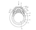
図1は本発明に係るサイドキャップ式のボールねじを説明する説明図、図2は、その要部を説明するための図1での径方向断面図である。また、図3および図4は、それぞれ図2でのE方向矢視図であり、図3ではサイドキャップ装着前のナットを示しており、図4では本発明に係るサイドキャップを装着した状態で示している。
Embodiments of the present invention will be described below with reference to the drawings as appropriate. In addition, about the part similar to description with the ball screw mentioned above, the same code | symbol is attached | subjected and demonstrated also in description in each following embodiment.
First, a first embodiment of the present invention will be described.
FIG. 1 is an explanatory view for explaining a side cap type ball screw according to the present invention, and FIG. 2 is a radial sectional view in FIG. 1 for explaining an essential part thereof. 3 and 4 are views in the direction of arrow E in FIG. 2, respectively. FIG. 3 shows a nut before the side cap is attached, and FIG. 4 shows a state where the side cap according to the present invention is attached. Show.
このボールねじ10は、図1ないし図2に示すように、ねじ軸12と、ナット14とを備えている。
ねじ軸12は、外周面に螺旋状のボール転動溝11を有する。ナット14は、ねじ軸12のボール転動溝11に対応する螺旋状のボール転動溝13を内周面に有する。そして、ナット14は、ねじ軸12に嵌合されており、ナット14のボール転動溝13とねじ軸12のボール転動溝11とが互いに対向して両者の間でボール軌道路8が構成されている。そのボール軌道路8には、転動体としての複数のボール15が転動可能に装填されている。
As shown in FIGS. 1 and 2, the
The
さらに、ナット14には、図3に示すように、その外周面に矩形状の平坦面からなるサイドキャップ取付け面16が形成されている。サイドキャップ取付け面16には、二個一組の長孔20が形成されている。この長孔20は、前記ボール転動溝11,13間で構成するボール軌道路8に連通して穿孔されている。
そして、このサイドキャップ取付け面16には、図4に示すように、ボール循環部材としてのサイドキャップ17が取り付けられる。ここで、サイドキャップ17は、一対の脚部19を有しており、その一対の脚部19を、サイドキャップ取付け面16に形成された上記長孔20に、ねじ軸12に対して垂直方向から、ほとんど隙間なく嵌め込み可能になっている(図1参照)。そして、図4に示すように、サイドキャップ17全体を覆う蓋形状のサイドキャップカバー26によって、サイドキャップ17全体をサイドキャップ取付け面16に向けて押さえられて、止めネジ18によってナット14に取付けられる。
Further, as shown in FIG. 3, the
As shown in FIG. 4, a
ここで、サイドキャップ17には、脚部19の内部にボール掬い上げ(戻し)通路21が形成されている(図2参照)。このボール掬い上げ(戻し)通路21は、当該通路の連続する方向を脚部19の外周壁面に対して傾けて形成されている。そして、ボールの循環通路方向に沿った方向に傾けて形成されている。そして、このボール掬い上げ(戻し)通路21がボール送り通路22に連通しており、ボール送り通路22、および一対のボール掬い上げ(戻し)通路21とによってボール循環通路27を構成している。
Here, a ball scooping (returning)
すなわち、このサイドキャップ17は、図2および図4に示すように、ボール掬い上げ(戻し)通路21とボール送り通路22とによってボール循環通路27の連続する方向に沿った一体構造からなるボール循環通路27を形成するとともに、サイドキャップ取付け面16に形成された長孔20に対して、容易に脚部19をはめ込むことができる構造としながらも、脚部19内に形成したボール掬い上げ(戻し)通路21でのボール15の進行方向を、ねじ軸12の略接線方向且つ両ボール転動溝11,13のリード角と略一致する方向に掬い上げ可能とする三次元的な構成となっている。そのため、ナット14の加工が簡単で、且つボール循環通路27(つまり、ボール掬い上げ(戻し)通路21およびボール送り通路22)の設計的自由度の向上を図ることを可能としている。
That is, as shown in FIGS. 2 and 4, the
そして、このボール循環通路27、並びにボール軌道路8とによってボール15の無限循環通路が構成される。なお、ねじ軸12の一端には、例えばモータ(図示せず)の出力軸がカップリングを介して連結可能になっており、これにより、ねじ軸12の回転により、ナット14がボール15の転動を介して軸方向に移動可能になっている。
次に、上述のサイドキャップ17のもつ分割構造について詳しく説明する。なお、図5および図6は、本発明に係るサイドキャップを示す説明図であり、図5はサイドキャップの説明的斜視図、図6は、そのサイドキャップを分割した、一方のサイドキャップ構成部材を示す説明的斜視図である。
The
Next, the divided structure of the
このサイドキャップ17は、樹脂成形により製作されており、図5に示すように、例えば樹脂材をモールド成形してなる一対のボール循環部材構成部材であるサイドキャップ構成部材23,23を組み合わせて構成されている。ここで、同図に符号PLで示す線は、ボール循環部材17を各サイドキャップ構成部材23に分割する分割線を示している。
このサイドキャップ17は、図6に示すように、ボール掬い上げ(戻し)通路21およびボール送り通路22からなるボール循環通路27が、その内側に形成され、ボール15の進行方向に沿って点対称に二つに分割されたサイドキャップ構成部材23から構成される。そのため、同図に示すように、各サイドキャップ構成部材23が相互に分割線PLで分割される部分では、分割面23d(相互の合わせ面ともなる)が生じる。
The
As shown in FIG. 6, the
次に、このサイドキャップ構成部材23相互の分割線PL(あるいは分割面23d)についてより詳しく説明する。なお、図7は、サイドキャップの分割線の要部(図6でのF部周辺)を拡大して示す説明図であり、同図では、本発明に係るボール掬い上げ部の掬い上げ基端部での分割例を示している。また、図8および図9は、本発明に係る一対のサイドキャップ構成部材同士による掬い上げ基端部の近傍での周壁の組合わせ状態を説明する説明図である。
上述したように、このサイドキャップ17は、二つのサイドキャップ構成部材23に分割線PLから分割されているため、一対のサイドキャップ構成部材23,23同士が、分割面(合わせ面)23dをそれぞれ有している(図6参照)。
Next, the dividing line PL (or dividing
As described above, since the
ところで、図7に示すように、サイドキャップ17には、サイドキャップ17のボール掬い上げ(戻し)通路21の先端部分に、ボール掬い上げ部24を有している。ボール掬い上げ部24は、ボール軌道路8内を転動するボール15を、ボール軌道路8からボール掬い上げ(戻し)通路21へ円滑に掬い上げるために、ねじ軸12のボール転動溝11に挿入可能な舌状の形状をしており、ボール転動溝11に向けてボール掬い上げ(戻し)通路21から突出して形成される。そのため、脚部19内に形成したボール掬い上げ(戻し)通路21とボール掬い上げ部24とを繋ぐ部分である掬い上げ基端部24aには、例えば鋭角をなすV字状の溝部である切欠き部25が形成されることになる。
Incidentally, as shown in FIG. 7, the
ここで、本発明に係るサイドキャップ17では、図7に示すように、分割線PLが、一対の脚部19の、それぞれの切欠き部25の最も深い部分を通る位置で形成されている。すなわち、サイドキャップ17を二つのサイドキャップ構成部材23,23に分ける分割線PLの位置は、掬い上げ基端部24aで生じる各切欠き部25を、つまり、一方の側での切欠き部25と他方の側での切欠き部25とを、そのV字状の頂点でそれぞれ予め分断して各々の分割面23dを形成するようになっている。
Here, in the
また、各切欠き部25を通る分割線PLは、掬い上げ基端部24aの近傍で、同図に符号23fで示すように、円弧をもち、その円弧と直線部とが連続する部分からなる周壁延出部で、なだらかに繋がるように設定されている。換言すれば、図6に示すように、ボール循環部材構成部材23の分割面23dは、掬い上げ基端部24aの近傍(図6に示すF部)において、その掬い上げ基端部24aでの分割線PLを、ボール軌道路8でのボール15の中心の軌跡BCDに対し、ボール掬い上げ部24の反対の側(同図での脚部19側)をボール掬い上げ部24の側にずらしてなる周壁延出部23fを有する。そのため、掬い上げ基端部24aでの分割面23dは、この周壁延出部23fによる、なだらかな稜線によって分割されているため、掬い上げ基端部24aでの応力集中を、より好適に緩和可能になっている。なお、同図での符号Zは、ボール15を掬い上げる掬い上げ点を示している。なおまた、サイドキャップ17全体に渡ってなされる分割において、掬い上げ基端部24aの近傍以外の部分での分割線PLは、ボール中心の軌跡に合わせて、ほぼ同等にボールの周囲を取り囲むように均等に設定される。
Further, the dividing line PL passing through each
次に、本発明の第一の実施形態でのボールねじ10およびサイドキャップ17の作用・効果について説明する。
上述のように、このボールねじ10は、ナット14のサイドキャップ取付け面16にサイドキャップ17を取付けると、ボール転動溝11,13間を転動したボール15は、サイドキャップ17のボール掬い上げ部24によってボール転動溝11,13のリード角方向に掬い上げられてボール送り通路22内に円滑に導入される。そのため、このボールねじ10では、チューブ循環式ボールねじのように、ボール転動溝のリードが大きくなってもボール15の進行方向がボール15の循環部分で急激に変化するようなことがほとんどないので、ボール15を掬い上げる際にボール15の損傷や騒音等の発生を抑制でき、しかも、例えばエンドキャップ式ボールねじのように、ボールの循環回路数がねじ溝の条数分に限定される制約がないので、1回路当りのボール数(巻き数)を多くすることなく負荷容量を高めることができる。
Next, functions and effects of the
As described above, in the
また、このボールねじ10では、サイドキャップ17がボール15の進行方向に沿って二つに分割された一対のボール循環部材構成部材23,23から構成されているため、ボール転動溝11,13のリード角と一致する方向にボール15を掬い上げて再び初期位置に戻すボール循環通路27をサイドキャップ17内に樹脂成形等により容易に形成することができる。
さらに、このボールねじ10は、サイドキャップ17を、外形形状が同一の、一対のサイドキャップ構成部材23,23を組み合わせる構成としたことにより、サイドキャップ構成部材23,23を1つの成形型で成形でき、これにより、サイドキャップ17をより容易に製造することができる。
Further, in this
Further, the
さらにまた、このボールねじ10では、各サイドキャップ構成部材23,23の分割面23dは、ボール掬い上げ部24の掬い上げ基端部24aでの各切欠き部25を、切欠き部の最も深い部分でそれぞれ予め分断する分割線PLによって形成している。つまり、サイドキャップ17は、二つのサイドキャップ構成部材23,23に分ける分割線PLが、掬い上げ部基端部24aで生じる切り欠き部25を、それぞれ予め分断する位置で形成されている。これにより、従来、応力集中が問題となっていた掬い上げ基端部24aで、切欠き部25が実質的に形成されない。そのため、サイドキャップ17内を循環するボール15による衝撃が、サイドキャップ構成部材23に作用した場合であっても、掬い上げ基端部24a、あるいは掬い上げ基端部24aの近傍が起点となる疲労破壊が生じるおそれがほとんどない。したがって、ボールねじ10の高速運転性能や耐久性能を向上させることができる。
Furthermore, in this
ここで、上述したように、各切欠き部25の最も深い部分から分割線PLを開始(および終了)するような位置で分割すれば、つまり、掬い上げ基端部24aに切欠き部25が実質的に形成されないように分割すれば、掬い上げ基端部24aでの応力集中を好適に緩和可能であるが、その副作用として、ボール循環部材構成部材23の分割面を、ボール15の中心が描くボール軌跡に対して、ボール掬い上げ部24の反対の側をボール掬い上げ部24の側に向けてずらしているため、掬い上げ基端部24aの近傍での周壁によるボール15を拘束する性能が不安定になるおそれがある。
Here, as described above, if the dividing line PL is divided from the deepest portion of each
そこで、次に、本発明の第二の実施形態として、当該掬い上げ基端部での応力集中を緩和するとともに、掬い上げ基端部の近傍でのボール拘束性能も安定させ得る形状について説明する。
なお、この第二の実施形態は、上記説明した第一の実施形態でのサイドキャップ17に対して、上記周壁延出部23fの形状のみが異なっており、それ以外は上記説明した第一の実施形態と同様の構成である。そのため、ここでは、周壁延出部23fの形状のみについて説明し、その他の説明については省略する。
Then, next, as a second embodiment of the present invention, a shape that can relieve stress concentration at the scooping base end and stabilize ball restraining performance in the vicinity of the scooping base end will be described. .
Note that the second embodiment differs from the
この第二の実施形態のサイドキャップ17では、図8ないし図9に示すように、上記説明した第一の実施形態でのサイドキャップ17に対して、二つのサイドキャップ構成部材23,23において、上記分割線PLをずらして形成している周壁である周壁延出部23fを、他方のボール循環部材構成部材23での掬い上げ基端部24aの外側を覆うように延出させている。
In the
これにより、二つのボール循環部材構成部材23,23が、掬い上げ基端部24aでボールを取り囲む周壁の割合がそれぞれ異なる分割位置であっても、図8に示すように、一方が他方を覆うようにして相互に組み合わされることになる。そのため、掬い上げ基端部24aの近傍での周壁によるボール拘束性能を安定可能になっている。なお、同図での符号Oは、ボール15の中心位置を示している。
このように、第二の実施形態のサイドキャップ17では、周壁延出部23fを、掬い上げ基端部24aの近傍で、相互に外側を覆うようにして組み合わせることができる。したがって、掬い上げ基端部24aの近傍での周壁によるボール拘束性能も安定させることができる。
As a result, even if the two ball circulation
Thus, in the
以上説明したように、本発明に係るボールねじ10によれば、ボール循環部材であるサイドキャップ17において、ボール掬い上げ部24で、強度の弱い掬い上げ基端部24aの強度を改善することにより、高速運転性能や耐久性能を向上させ得るサイドキャップ17および、そのサイドキャップ17を備えたボールねじ10を提供することができる。
As described above, according to the
なお、本発明に係るボールねじは、上記各実施形態に限定されるものではなく、本発明の趣旨を逸脱しなければ種々の変形が可能である。
例えば、上記各実施形態に、さらに、分割面(合わせ面)23dに対して、相互の位置合わせをするための位置決め部として、突起部と穴部とをそれぞれに設ける構成としてもよい。なおまた、サイドキャップ17には止めネジ18を直接通すためのサイドキャップ取付け孔を穿設した構成としてもよい。
In addition, the ball screw which concerns on this invention is not limited to said each embodiment, A various deformation | transformation is possible unless it deviates from the meaning of this invention.
For example, each of the above embodiments may further include a protrusion and a hole provided as positioning portions for mutual alignment with respect to the split surface (mating surface) 23d. Further, the
また、上記各実施形態では、サイドキャップ17全体に渡ってなされる分割において、掬い上げ基端部24aでの近傍以外の部分での分割線PLが、ボール中心の軌跡に合わせて均等に設定される例で説明したが、これに限定されず、分割線の位置は均等割りでなくてもよい。しかし、ボール循環部材構成部材のそれぞれが、ボールに対して、ほぼ同等にボールの周囲を取り囲むことによってボールを拘束する性能を安定させる上では、掬い上げ基端部の近傍以外の部分での分割線PLは、ボール中心の軌跡に合わせて均等に設定されることが好ましい。
Further, in each of the above embodiments, in the division performed over the
また、例えば、上記各実施形態では、掬い上げ基端部24aに形成される切欠き部25の形状が、鋭角をなすV字状の溝部となっている例で説明したが、切欠き部25の形状は、V字状の溝に限定されない。すなわち、切欠き部としては、凹部あるいは溝等の「くぼみ」を含み、例えば切欠き部の形状がU字状ないしは半円状等であってもよい。
また、例えば、上記各実施形態では、ボールねじ10は、サイドキャップ17(サイドキャップ構成部材23,23)を樹脂で形成した例で説明したが、例えばサイドキャップ17を金属成形、例えば焼結鋼等の焼結材で形成したり、金属射出成形(MIM)により成形してもよく、このような構成とすることにより、樹脂の使用に適さない高温条件下でも使用することができる。
Further, for example, in each of the above-described embodiments, the description has been given of the example in which the shape of the
Further, for example, in each of the above embodiments, the
8 ボール軌道路
10、100 ボールねじ
11 ボール転動溝
12 ねじ軸
13 ボール転動溝
14 ナット
15 ボール
16 サイドキャップ取付け面(ボール循環部材取付け面)
17、170 サイドキャップ(ボール循環部材)
18 止めネジ
19、190 脚部
20 長孔
21、210 ボール掬い上げ(戻し)通路
22 ボール送り通路
23、230 サイドキャップ構成部材(ボール循環部材構成部材)
23d 分割面
23f 周壁延出部
24、240 ボール掬い上げ部
24a、240a 掬い上げ基端部
25 切欠き部
26 サイドキャップカバー
27 ボール循環通路
PL、PL’ 分割線
8
17, 170 Side cap (ball circulation member)
18
Claims (3)
前記ボール循環部材は、その内部を通る前記ボールの進行方向に延びる分割線に沿って分割された二つのボール循環部材構成部材を備えて構成されてなり、
前記分割線は、前記一方の側での前記切欠き部の最も深い部分と前記他方の側での前記切欠き部の最も深い部分とを通ることを特徴とするボール循環部材。 A screw shaft having a ball rolling groove on the outer peripheral surface, a nut having a ball rolling groove on the inner peripheral surface facing the outer peripheral surface of the screw shaft, and both the ball rolling grooves of the nut and the screw shaft are configured. A ball scooping part that scoops up the ball in the ball raceway from one side, and scooped up by the ball scooping part A ball circulation passage for returning the ball from the other side into the ball raceway, and a notch in a scooping base end portion, which is a portion where the integrally formed ball scooping portion and the ball circulation passage are connected A ball circulation member having a portion,
The ball circulation member is configured to include two ball circulation member constituent members divided along a parting line extending in the traveling direction of the ball passing through the inside,
The ball circulation member, wherein the dividing line passes through a deepest portion of the cutout portion on the one side and a deepest portion of the cutout portion on the other side.
Priority Applications (4)
| Application Number | Priority Date | Filing Date | Title |
|---|---|---|---|
| JP2004230730A JP4525233B2 (en) | 2004-08-06 | 2004-08-06 | Ball circulation member and ball screw |
| EP05017076A EP1624228B1 (en) | 2004-08-06 | 2005-08-05 | Ball circulating member and ball screw |
| CNB2005101098506A CN100441916C (en) | 2004-08-06 | 2005-08-08 | Ball circulating member and ball screw |
| US11/198,231 US20060032323A1 (en) | 2004-08-06 | 2005-08-08 | Ball circulating member and ball screw |
Applications Claiming Priority (1)
| Application Number | Priority Date | Filing Date | Title |
|---|---|---|---|
| JP2004230730A JP4525233B2 (en) | 2004-08-06 | 2004-08-06 | Ball circulation member and ball screw |
Publications (2)
| Publication Number | Publication Date |
|---|---|
| JP2006046570A true JP2006046570A (en) | 2006-02-16 |
| JP4525233B2 JP4525233B2 (en) | 2010-08-18 |
Family
ID=36025361
Family Applications (1)
| Application Number | Title | Priority Date | Filing Date |
|---|---|---|---|
| JP2004230730A Expired - Lifetime JP4525233B2 (en) | 2004-08-06 | 2004-08-06 | Ball circulation member and ball screw |
Country Status (2)
| Country | Link |
|---|---|
| JP (1) | JP4525233B2 (en) |
| CN (1) | CN100441916C (en) |
Cited By (2)
| Publication number | Priority date | Publication date | Assignee | Title |
|---|---|---|---|---|
| WO2012077247A1 (en) * | 2010-12-08 | 2012-06-14 | 日本精工株式会社 | Ball screw device |
| WO2015102109A1 (en) * | 2014-01-06 | 2015-07-09 | 日本精工株式会社 | Ball screw |
Families Citing this family (3)
| Publication number | Priority date | Publication date | Assignee | Title |
|---|---|---|---|---|
| DE102014221135B3 (en) | 2014-10-17 | 2016-01-07 | Schaeffler Technologies AG & Co. KG | Ball screw nut |
| CN110375046B (en) * | 2018-04-13 | 2022-07-19 | 银鼎精密元件(上海)有限公司 | Ball screw structure |
| CN110375045A (en) * | 2018-04-13 | 2019-10-25 | 银鼎精密元件(上海)有限公司 | Two-piece return pipe and ball screw structure |
Citations (3)
| Publication number | Priority date | Publication date | Assignee | Title |
|---|---|---|---|---|
| JPH0550220U (en) * | 1991-12-13 | 1993-07-02 | 日本精工株式会社 | Ball screw device |
| JP2002310254A (en) * | 2001-04-13 | 2002-10-23 | Koyo Seiko Co Ltd | Ball screw device and electric power steering device using the same |
| JP2003343683A (en) * | 2002-05-30 | 2003-12-03 | Nsk Ltd | Linear motion device |
Family Cites Families (5)
| Publication number | Priority date | Publication date | Assignee | Title |
|---|---|---|---|---|
| FR2325859A1 (en) * | 1975-03-12 | 1977-04-22 | Legueu Pierre | Ball screw for machine tool use - has transfer passage with lip to pick up balls and bent through right angle |
| JP3993504B2 (en) * | 2001-12-05 | 2007-10-17 | Thk株式会社 | Ball screw circulation parts and ball screw |
| JP2003294105A (en) * | 2002-03-29 | 2003-10-15 | Nsk Ltd | Screw feed device |
| JP2004108455A (en) * | 2002-09-17 | 2004-04-08 | Nsk Ltd | Ball screw device |
| CN2597759Y (en) * | 2002-12-27 | 2004-01-07 | 银泰科技股份有限公司 | Circulation flow guide pipe of nut seat of ball guide screw |
-
2004
- 2004-08-06 JP JP2004230730A patent/JP4525233B2/en not_active Expired - Lifetime
-
2005
- 2005-08-08 CN CNB2005101098506A patent/CN100441916C/en active Active
Patent Citations (3)
| Publication number | Priority date | Publication date | Assignee | Title |
|---|---|---|---|---|
| JPH0550220U (en) * | 1991-12-13 | 1993-07-02 | 日本精工株式会社 | Ball screw device |
| JP2002310254A (en) * | 2001-04-13 | 2002-10-23 | Koyo Seiko Co Ltd | Ball screw device and electric power steering device using the same |
| JP2003343683A (en) * | 2002-05-30 | 2003-12-03 | Nsk Ltd | Linear motion device |
Cited By (4)
| Publication number | Priority date | Publication date | Assignee | Title |
|---|---|---|---|---|
| WO2012077247A1 (en) * | 2010-12-08 | 2012-06-14 | 日本精工株式会社 | Ball screw device |
| JP5500268B2 (en) * | 2010-12-08 | 2014-05-21 | 日本精工株式会社 | Ball screw device |
| US9003911B2 (en) | 2010-12-08 | 2015-04-14 | Nsk Ltd. | Ball screw device |
| WO2015102109A1 (en) * | 2014-01-06 | 2015-07-09 | 日本精工株式会社 | Ball screw |
Also Published As
| Publication number | Publication date |
|---|---|
| JP4525233B2 (en) | 2010-08-18 |
| CN1740590A (en) | 2006-03-01 |
| CN100441916C (en) | 2008-12-10 |
Similar Documents
| Publication | Publication Date | Title |
|---|---|---|
| US6675669B2 (en) | Ball screw apparatus | |
| JP5500268B2 (en) | Ball screw device | |
| US20070186707A1 (en) | Ball screw apparatus | |
| US20050252321A1 (en) | Ball screw drive | |
| JP4525233B2 (en) | Ball circulation member and ball screw | |
| US20030213323A1 (en) | Screw feed apparatus | |
| US7921743B2 (en) | Ball screw device | |
| WO2012081143A1 (en) | Ball screw device | |
| JP2003307263A (en) | Ball screw mechanism | |
| US7207234B2 (en) | Ball screw | |
| KR20050107394A (en) | Ball screw device | |
| JP7327890B2 (en) | ball screw device | |
| US20060032323A1 (en) | Ball circulating member and ball screw | |
| TW201925651A (en) | Ball screw spline | |
| JP2017078439A (en) | Ball Screw | |
| JP2005155720A (en) | Screw device and its manufacturing method | |
| JP4110834B2 (en) | Ball screw | |
| JP2006052780A (en) | Ball circulation member and ball screw | |
| JP2012137154A (en) | Ball screw circulation part and ball screw | |
| JP6586791B2 (en) | Ball screw | |
| JP5318894B2 (en) | Circulation unit and ball screw using the same | |
| JP2003343680A (en) | Ball screw | |
| JP2021076211A (en) | Ball screw | |
| JP2017009096A (en) | Ball Screw | |
| JP2022029291A (en) | Ball circulation member and ball screw |
Legal Events
| Date | Code | Title | Description |
|---|---|---|---|
| A621 | Written request for application examination |
Free format text: JAPANESE INTERMEDIATE CODE: A621 Effective date: 20070207 |
|
| A977 | Report on retrieval |
Free format text: JAPANESE INTERMEDIATE CODE: A971007 Effective date: 20091119 |
|
| A131 | Notification of reasons for refusal |
Free format text: JAPANESE INTERMEDIATE CODE: A131 Effective date: 20091201 |
|
| A521 | Request for written amendment filed |
Free format text: JAPANESE INTERMEDIATE CODE: A523 Effective date: 20100112 |
|
| A131 | Notification of reasons for refusal |
Free format text: JAPANESE INTERMEDIATE CODE: A131 Effective date: 20100330 |
|
| A521 | Request for written amendment filed |
Free format text: JAPANESE INTERMEDIATE CODE: A523 Effective date: 20100414 |
|
| TRDD | Decision of grant or rejection written | ||
| A01 | Written decision to grant a patent or to grant a registration (utility model) |
Free format text: JAPANESE INTERMEDIATE CODE: A01 Effective date: 20100511 |
|
| A01 | Written decision to grant a patent or to grant a registration (utility model) |
Free format text: JAPANESE INTERMEDIATE CODE: A01 |
|
| A61 | First payment of annual fees (during grant procedure) |
Free format text: JAPANESE INTERMEDIATE CODE: A61 Effective date: 20100524 |
|
| FPAY | Renewal fee payment (event date is renewal date of database) |
Free format text: PAYMENT UNTIL: 20130611 Year of fee payment: 3 |
|
| R150 | Certificate of patent or registration of utility model |
Ref document number: 4525233 Country of ref document: JP Free format text: JAPANESE INTERMEDIATE CODE: R150 Free format text: JAPANESE INTERMEDIATE CODE: R150 |
|
| FPAY | Renewal fee payment (event date is renewal date of database) |
Free format text: PAYMENT UNTIL: 20130611 Year of fee payment: 3 |
|
| FPAY | Renewal fee payment (event date is renewal date of database) |
Free format text: PAYMENT UNTIL: 20140611 Year of fee payment: 4 |
|
| EXPY | Cancellation because of completion of term |