JP2006005438A - Image processing apparatus and method - Google Patents
Image processing apparatus and method Download PDFInfo
- Publication number
- JP2006005438A JP2006005438A JP2004176950A JP2004176950A JP2006005438A JP 2006005438 A JP2006005438 A JP 2006005438A JP 2004176950 A JP2004176950 A JP 2004176950A JP 2004176950 A JP2004176950 A JP 2004176950A JP 2006005438 A JP2006005438 A JP 2006005438A
- Authority
- JP
- Japan
- Prior art keywords
- prediction mode
- block
- determined
- data
- prediction
- Prior art date
- Legal status (The legal status is an assumption and is not a legal conclusion. Google has not performed a legal analysis and makes no representation as to the accuracy of the status listed.)
- Pending
Links
Images


Landscapes
- Compression Or Coding Systems Of Tv Signals (AREA)
- Compression, Expansion, Code Conversion, And Decoders (AREA)
Abstract
【課題】2次元画像を構成する複数のブロックの各々のイントラ予測の予測モードを、符号化効率の観点から適切に決定できる画像処理装置を提供する。
【解決手段】 イントラ予測回路において、MPM選択回路52が処理対象のブロックデータの周囲の予め決められたイントラ予測モードが未決定の場合に、既に決定しているイントラ予測モードを基に、予測モード指定データPREV,REMの生成に用いられるイントラ予測モードを擬似的に特定する。
【選択図】 図8
An image processing apparatus capable of appropriately determining a prediction mode of intra prediction of each of a plurality of blocks constituting a two-dimensional image from the viewpoint of coding efficiency.
In an intra prediction circuit, when a predetermined intra prediction mode around block data to be processed by an MPM selection circuit 52 has not been determined, a prediction mode is determined based on the already determined intra prediction mode. The intra prediction mode used for generating the designated data PREV and REM is specified in a pseudo manner.
[Selection] Figure 8
Description
本発明は、画像データのイントラ予測を行う画像処理装置およびその方法に関する。 The present invention relates to an image processing apparatus and method for performing intra prediction of image data.
近年、画像データをデジタルとして取り扱い、その際、効率の高い情報の伝送、蓄積を目的とし、画像情報特有の冗長性を利用して、離散コサイン変換等の直交変換と動き補償により圧縮するMPEG(Moving Picture Experts Group)2,4などの方式に準拠した装置が、放送局などの情報配信、及び一般家庭における情報受信の双方において普及しつつある。 In recent years, image data has been handled as digital data. At that time, MPEG (compressed by orthogonal transformation such as discrete cosine transformation and motion compensation is used for the purpose of efficient transmission and storage of information, and using redundancy unique to image information. Devices conforming to the system such as Moving Picture Experts Group (2, 4) are becoming widespread in both information distribution at broadcasting stations and information reception in general households.
MPEGに続いて、符号化効率をさらに向上させるMPEG−AVC(Advanced Video
Coding) と呼ばれる符号化方式が提案されている。
MPEG−AVCでは、MPEGと同様にイントラ予測が行われるが、複数のイントラ予測モードが規定され、各ブロックデータの予測符号化量を最小にするイントラ予測モードを決定する。
MPEG−AVCのイントラ予測では、例えば、上記決定したイントラ予測モードを示す予測モード指定データをヘッダデータとして符号化データに付加する。
この予測モード指定データは、処理対象のブロックデータの周囲のブロックデータについて決定されたイントラ予測モードを基に生成され、その予測符号量は当該周囲のブロックデータについて決定されたイントラ予測モードに依存する。
ところで、上記ブロックデータのイントラ予測モードとしては、そのブロックデータの予測符号量を最小にするものが選択して決定するが、当該予測符号量は当該ブロックデータの予測モード指定データの予測符号量に依存する。
Following MPEG, MPEG-AVC (Advanced Video
A coding method called “Coding” has been proposed.
In MPEG-AVC, intra prediction is performed as in MPEG, but a plurality of intra prediction modes are defined, and an intra prediction mode that minimizes the prediction coding amount of each block data is determined.
In the MPEG-AVC intra prediction, for example, prediction mode designating data indicating the determined intra prediction mode is added to encoded data as header data.
The prediction mode designating data is generated based on the intra prediction mode determined for the block data around the block data to be processed, and the prediction code amount depends on the intra prediction mode determined for the surrounding block data. .
By the way, as the intra prediction mode of the block data, a block data that minimizes the prediction code amount of the block data is selected and determined. However, the prediction code amount corresponds to the prediction code amount of the prediction mode designation data of the block data. Dependent.
ところで、上述したMPEG−AVCのイントラ予測では、2次元画像データを構成する複数のブロックデータのイントラ予測モードは、所定の順序でパイプライン処理により決定される。
そのため、処理対象のブロックデータのイントラ予測モードを決定するタイミングで、当該ブロックデータの上記周囲のブロックデータのイントラ予測モードが未決定となる場合がある。この場合に、処理対象のブロックデータについての予測モード指定データが生成できず、その結果、その予測符号量が得られなく、イントラ予測モードを決定できない場合がある。
By the way, in the above-described MPEG-AVC intra prediction, the intra prediction modes of a plurality of block data constituting two-dimensional image data are determined by pipeline processing in a predetermined order.
For this reason, the intra prediction mode of the surrounding block data of the block data may not be determined at the timing of determining the intra prediction mode of the block data to be processed. In this case, the prediction mode designation data for the block data to be processed cannot be generated. As a result, the prediction code amount cannot be obtained, and the intra prediction mode may not be determined.
本発明は上述した従来技術の問題点を解決するために、2次元画像を構成する複数のブロックの各々のイントラ予測の予測モードを、符号化効率の観点から適切に決定できる画像処理装置および画像処理方法を提供することを目的とする。 In order to solve the above-described problems of the prior art, the present invention provides an image processing apparatus and an image that can appropriately determine the prediction mode of intra prediction of each of a plurality of blocks constituting a two-dimensional image from the viewpoint of coding efficiency. An object is to provide a processing method.
上述した従来技術の問題点を解決し、上述した目的を達成するため、第1の発明の画像処理装置は、2次元画像を構成する複数のブロックの各々を所定の順序で選択し、当該選択したブロックについて、予測モードによって規定される当該ブロック以外のブロックの画素データを基にイントラ予測を行い、複数の前記予測モードのうち符号化効率が所定の基準を満たす前記予測モードを、前記選択したブロックの第1の前記予測モードとして決定する画像処理装置であって、前記選択されたブロック以外の予め決められたブロックの前記第1の予測モードが既に決定されているか否かを判断する判断手段と、前記予め決められたブロックの前記第1の予測モードが既に決定されていると前記判断手段が判断した場合に、前記予め決められた前記ブロックの前記第1の予測モードを基に、前記選択したブロックに対して決定される前記第1の予測モードを指定するための予測モード指定データを生成するために用いられる第2の前記予測モードを特定し、前記予め決められた前記ブロックの前記第1の予測モードが未決定であると前記判断手段が判断した場合に、前記予め決められた前記ブロック以外のブロックの既に決定された前記第1の予測モードを基に、前記第2の予測モードを特定する予測モード特定手段と、前記複数の予測モードの各々について、当該予測モードが前記選択されたブロックの前記第1の予測モードとして決定された場合の前記予測モード指定データの予測符号量を、前記予測モード特定手段が特定した前記第2の予測モードを基に決定する符号量決定手段と、前記選択したブロックについて、前記複数の予測モードのうち符号化効率が所定の基準を満たす前記第1の予測モードを、前記符号量決定手段が決定した前記予測符号量を基に決定する予測モード決定手段とを有する。 In order to solve the above-described problems of the prior art and achieve the above-described object, the image processing apparatus of the first invention selects each of a plurality of blocks constituting a two-dimensional image in a predetermined order, and performs the selection. The intra prediction is performed based on pixel data of blocks other than the block defined by the prediction mode, and the prediction mode in which the encoding efficiency satisfies a predetermined criterion is selected from the plurality of prediction modes. An image processing apparatus for determining a first prediction mode of a block, wherein the determination unit determines whether or not the first prediction mode of a predetermined block other than the selected block has already been determined. And when the determining means determines that the first prediction mode of the predetermined block has already been determined, The second prediction mode used to generate prediction mode designation data for designating the first prediction mode determined for the selected block based on the first prediction mode of the block And when the determination means determines that the first prediction mode of the predetermined block has not been determined, the previously determined blocks other than the predetermined block have been determined. Based on one prediction mode, prediction mode specifying means for specifying the second prediction mode, and for each of the plurality of prediction modes, the prediction mode is determined as the first prediction mode of the selected block. A code amount determining unit that determines a prediction code amount of the prediction mode designating data when the prediction mode is specified based on the second prediction mode specified by the prediction mode specifying unit A prediction mode for determining, for the selected block, the first prediction mode in which the encoding efficiency satisfies a predetermined criterion among the plurality of prediction modes based on the prediction code amount determined by the code amount determination unit Determination means.
第1の発明の画像処理装置の作用は以下のようになる。
判断手段が、選択されたブロック以外の予め決められたブロックの前記第1の予測モードが既に決定されているか否かを判断する。
次に、予測モード特定手段が、前記予め決められたブロックの前記第1の予測モードが既に決定されていると前記判断手段が判断した場合に、前記予め決められた前記ブロックの前記第1の予測モードを基に、前記選択したブロックに対して決定される前記第1の予測モードを指定するための予測モード指定データを生成するために用いられる第2の前記予測モードを特定する。
一方、前記予測モード特定手段は、前記予め決められた前記ブロックの前記第1の予測モードが未決定であると前記判断手段が判断した場合に、前記予め決められた前記ブロック以外のブロックの既に決定された前記第1の予測モードを基に、前記第2の予測モードを特定する。
次に、符号量決定手段が、前記複数の予測モードの各々について、当該予測モードが前記選択されたブロックの前記第1の予測モードとして決定された場合の前記予測モード指定データの予測符号量を、前記予測モード特定手段が特定した前記第2の予測モードを基に決定する。
次に、予測モード決定手段が、前記選択したブロックについて、前記複数の予測モードのうち符号化効率が所定の基準を満たす前記第1の予測モードを、前記符号量決定手段が決定した前記予測符号量を基に決定する。
The operation of the image processing apparatus of the first invention is as follows.
A determination means determines whether the first prediction mode of a predetermined block other than the selected block has already been determined.
Next, when the determination unit determines that the first prediction mode of the predetermined block has already been determined, the prediction mode specifying unit determines the first of the predetermined block. Based on the prediction mode, the second prediction mode used to generate prediction mode specifying data for specifying the first prediction mode determined for the selected block is specified.
On the other hand, when the determination unit determines that the first prediction mode of the predetermined block is undecided, the prediction mode specifying unit has already detected blocks other than the predetermined block. The second prediction mode is specified based on the determined first prediction mode.
Next, for each of the plurality of prediction modes, a code amount determination unit determines a prediction code amount of the prediction mode designation data when the prediction mode is determined as the first prediction mode of the selected block. The determination is made based on the second prediction mode specified by the prediction mode specifying means.
Next, for the selected block, the prediction code determined by the code amount determination unit for the selected block is the first prediction mode in which the encoding efficiency satisfies a predetermined criterion among the plurality of prediction modes. Determine based on amount.
第2の発明の画像処理方法は、2次元画像を構成する複数のブロックの各々を所定の順序で選択し、当該選択したブロックについて、予測モードによって規定される当該ブロック以外のブロックの画素データを基にイントラ予測を行い、複数の前記予測モードのうち符号化効率が所定の基準を満たす前記予測モードを前記選択したブロックの第1の前記予測モードとして決定する画像処理方法であって、前記選択されたブロック以外の予め決められたブロックの前記第1の予測モードが既に決定されているか否かを判断する第1の工程と、前記予め決められたブロックの前記第1の予測モードが既に決定されていると前記第1の工程で判断した場合に、前記予め決められた前記ブロックの前記第1の予測モードを基に、前記選択したブロックに対して決定される前記第1の予測モードを指定するための予測モード指定データを生成するために用いられる第2の前記予測モードを特定し、前記予め決められた前記ブロックの前記第1の予測モードが未だ決定されていないと前記第1の工程で判断した場合に、前記予め決められた前記ブロック以外のブロックの既に決定された前記第1の予測モードを基に、前記第2の予測モードを特定する第2の工程と、前記複数の予測モードの各々について、当該予測モードが前記選択されたブロックの前記第1の予測モードとして決定された場合の前記予測モード指定データの予測符号量を、前記第2の工程で特定した前記第2の予測モードを基に決定する第3の工程と、前記選択したブロックについて、前記複数の予測モードのうち符号化効率が所定の基準を満たす前記第1の予測モードを、前記第3の工程で決定した前記予測符号量を基に決定する第4の工程とを有する。 In the image processing method of the second invention, each of a plurality of blocks constituting a two-dimensional image is selected in a predetermined order, and pixel data of blocks other than the block defined by the prediction mode is selected for the selected block. An image processing method for performing intra prediction based on the prediction mode, and determining the prediction mode satisfying a predetermined standard of coding efficiency among a plurality of the prediction modes as the first prediction mode of the selected block, A first step of determining whether the first prediction mode of a predetermined block other than the determined block has already been determined, and the first prediction mode of the predetermined block has already been determined The selected block based on the first prediction mode of the block determined in advance when it is determined in the first step that Identifying the second prediction mode used to generate prediction mode designating data for designating the first prediction mode determined for the first prediction of the predetermined block When it is determined in the first step that a mode has not yet been determined, the second prediction mode is based on the first prediction mode already determined for a block other than the predetermined block. A prediction code amount of the prediction mode designation data when the prediction mode is determined as the first prediction mode of the selected block for each of the plurality of prediction modes. A third step of determining based on the second prediction mode identified in the second step, and encoding efficiency among the plurality of prediction modes for the selected block. And a fourth step of determining the first prediction mode which satisfies a predetermined standard, based on the predicted code amount determined in the third step.
本発明によれば、2次元画像を構成する複数のブロックの各々のイントラ予測の予測モードを、符号化効率の観点から適切に決定できる画像処理装置および画像処理方法を提供することができる。 ADVANTAGE OF THE INVENTION According to this invention, the image processing apparatus and image processing method which can determine appropriately the prediction mode of each intra prediction of the some block which comprises a two-dimensional image from a viewpoint of encoding efficiency can be provided.
以下、本発明の画像処理装置および画像処理方法について説明する。
<第1実施形態>
先ず、本実施形態の構成要素と本発明の構成要素との対応関係を説明する。
本実施形態の4x4のブロック(ブロックデータ)が本発明のブロック(ブロックデータ)に対応している。
また、本実施形態のマクロブロックが、本発明のマクロブロックに対応している。
また、本実施形態のイントラ予測モードが、本発明の予測モードに対応している。
また、本実施形態のイントラ予測モードS56が、本発明の第1の予測モードに対応している。
また、本実施形態のMPMデータS52が示すイントラ予測モードが、本発明の第2の予測モードに対応している。
また、本実施形態の予測モード指定データPREV,REMが、本発明の予測モード指定データに対応している。
また、図8に示すイントラ予測回路43の予測モード決定有無判断回路51が第1の発明の判断手段に対応し、MPM選択回路52が第1の発明の予測モード特定手段に対応し、予測モード指定データ・符号量生成(推定)回路53が第1の発明の符号量決定(推定)手段に対応し、予測モード決定回路56が第1の発明の予測モード決定手段に対応している。
また、図2に示す可逆符号化回路27が、第1の発明の符号化手段に対応している。
Hereinafter, an image processing apparatus and an image processing method of the present invention will be described.
<First Embodiment>
First, the correspondence between the components of the present embodiment and the components of the present invention will be described.
The 4 × 4 block (block data) of this embodiment corresponds to the block (block data) of the present invention.
Further, the macroblock of this embodiment corresponds to the macroblock of the present invention.
Further, the intra prediction mode of the present embodiment corresponds to the prediction mode of the present invention.
Further, the intra prediction mode S56 of the present embodiment corresponds to the first prediction mode of the present invention.
Further, the intra prediction mode indicated by the MPM data S52 of the present embodiment corresponds to the second prediction mode of the present invention.
Further, the prediction mode designation data PREV and REM of the present embodiment correspond to the prediction mode designation data of the present invention.
Also, the prediction mode determination presence /
A
以下、本実施形態の画像処理装置および画像処理方法が適用される通信システムについて説明する。
図1は、本実施形態の通信システム1の概念図である。
図1に示すように、通信システム1は、送信側に設けられた符号化装置2と、受信側に設けられた復号装置3とを有する。
通信システム1では、送信側の符号化装置2において、離散コサイン変換やカルーネン・レーベ変換などの直交変換と動き補償によって圧縮したフレーム画像データ(ビットストリーム)を生成し、当該フレーム画像データを変調した後に、衛星放送波、ケーブルTV網、電話回線網、携帯電話回線網などの伝送媒体を介して送信する。
受信側では、受信した画像信号を復調した後に、上記変調時の直交変換の逆変換と動き補償によって伸張したフレーム画像データを生成して利用する。
なお、上記伝送媒体は、光ディスク、磁気ディスクおよび半導体メモリなどの記録媒体であってもよい。
図1に示す復号装置3は,符号化装置2の符号化に対応した復号を行う。
Hereinafter, a communication system to which the image processing apparatus and the image processing method of the present embodiment are applied will be described.
FIG. 1 is a conceptual diagram of a
As shown in FIG. 1, the
In the
On the receiving side, after demodulating the received image signal, frame image data expanded by inverse transformation of orthogonal transformation and motion compensation at the time of modulation is generated and used.
The transmission medium may be a recording medium such as an optical disk, a magnetic disk, and a semiconductor memory.
The
以下、図1に示す符号化装置2について説明する。
図2は、図1に示す符号化装置2の全体構成図である。
図2に示すように、符号化装置2は、例えば、A/D変換回路22、画面並べ替え回路23、演算回路24、直交変換回路25、量子化回路26、可逆符号化回路27、バッファ28、逆量子化回路29、逆直交変換回路30、フレームメモリ31、レート制御回路32、加算回路33、デブロックフィルタ34、動き予測・補償回路41、イントラ予測回路43および選択回路44を有する。
本実施形態は、イントラ予測回路43の処理に特に特徴を有している。
Hereinafter, the
FIG. 2 is an overall configuration diagram of the
As shown in FIG. 2, the
The present embodiment is particularly characterized in the processing of the
以下、符号化装置2の構成要素について説明する。
A/D変換回路22は、入力されたアナログの輝度信号Y、色差信号Pb,Prから構成される原画像信号をデジタルの画像信号に変換し、これを画面並べ替え回路23に出力する。
画面並べ替え回路23は、A/D変換回路22から入力した原画像信号内のフレーム画像信号を、そのピクチャタイプI,P,BからなるGOP(Group Of Pictures) 構造に応じて、符号化する順番に並べ替えた原画像データ(フレーム画像データ)S23を演算回路24および動き予測・補償回路41に出力する。
Hereinafter, components of the
The A /
The
演算回路24は、原画像データS23と、選択回路44から入力した予測画像データPIとの差分を示す画像データS24を生成し、これを直交変換回路25に出力する。
直交変換回路25は、画像データS24に離散コサイン変換やカルーネン・レーベ変換などの直交変換を施して画像データ(例えばDCT係数信号)S25を生成し、これを量子化回路26に出力する。
量子化回路26は、レート制御回路32から入力した量子化スケールで、画像データS25を量子化して画像データS26を生成し、これを可逆符号化回路27および逆量子化回路29に出力する。
The
The
The
可逆符号化回路27は、画像データS26を可変長符号化あるいは算術符号化した画像データをバッファ28に格納する。
このとき、可逆符号化回路27は、動き予測・補償回路41から入力した動きベクトルMVあるいはその差分を符号化してヘッダデータに格納する。
また、可逆符号化回路27は、イントラ予測回路43から入力した予測モード指定データPREV,REMを符号化してヘッダデータに格納する。
The
At this time, the
The
バッファ28に格納された画像データは、変調等された後に送信される。
逆量子化回路29は、画像データS26を逆量子化した信号を生成し、逆直交変換回路30に出力する。
逆直交変換回路30は、逆量子化回路29から入力した画像データに、直交変換回路25における直交変換の逆変換を施して生成した画像データを加算回路33に出力する。
加算回路33は、逆直交変換回路30から入力した画像データと、選択回路44から入力した予測画像データPIとを加算して再構成画像データを生成し、これをデブロックフィルタ34に出力する。
デブロックフィルタ34は、加算回路33から入力した再構成画像データのブロック歪みを除去した画像データを、参照画像データとしてフレームメモリ31に書き込む。
レート制御回路32は、バッファ23から読み出した画像データを基に量子化スケールを生成し、これを量子化回路26に出力する。
The image data stored in the
The
The inverse
The
The
The
動き予測・補償回路41は、フレームメモリ31に記憶された参照画像データREF内を探索して、原画像データS23内の符号化対象のブロックデータの動きベクトルMVを生成する。
動き予測・補償回路41は、当該探索において、予測画像データPImおよび指標データCOSTmを生成する。指標データCOSTmは、原画像データS23内のブロックデータと予測画像データPImとの差分を符号化した場合の符号量を判断する指標となるデータである。
動き予測・補償回路41は、選択回路44から動き予測・補償を選択したことを示す選択信号S44を入力すると、動きベクトルMVを可逆符号化回路27に出力する。
また、動き予測・補償回路41は、予測画像データPImおよび指標データCOSTmを選択回路44に出力する。
The motion prediction /
In the search, the motion prediction /
When the motion prediction /
In addition, the motion prediction /
〔イントラ予測回路43〕
イントラ予測回路43は、予め規定された4x4、16x16などの複数のサイズのブロックデータを単位として、16x16のマクロブロックMBのイントラ予測処理を行う。
本実施形態では、4x4および16x16のサイズのブロックデータを単位としてイントラ予測を行う場合を例示する。
特に、本実施形態では、4x4のブロックデータについてのイントラ予測モードを主として説明する。
4x4および16x16のサイズのブロックデータを単位としてイントラ予測の各々には、その予測方法が異なる複数のイントラ予測モードが規定されている。
以下、4x4のサイズのブロックデータを単位としたイントラ予測について説明する。
イントラ予測回路43は、画面並べ替え回路23から入力した原画像データS23内の符号化対象の4x4のブロックデータに対して、複数のイントラ予測モードの各々に応じた処理を施し、各イントラ予測モードの予測画像データPIiおよび指標データCOSTiを生成する。
ここで、イントラ予測回路43は、原画像データS23内の符号化対象の4x4のブロックデータと予測画像データPIiとの画素データ間の差分の自乗和あるいは当該自乗和にアダマ−ル変換を施した値と、ヘッダデータの符号量の予測値とを加算して指標データCOSTiを生成する。
イントラ予測回路43は、上記複数のイントラ予測モードのうち指標データCOSTiを最小にする(本発明の「符号化効率が所定の基準を満たす」)イントラ予測モードを決定する。
[Intra prediction circuit 43]
The
In this embodiment, a case where intra prediction is performed in units of block data having a size of 4 × 4 and 16 × 16 is illustrated.
In particular, in the present embodiment, an intra prediction mode for 4 × 4 block data will be mainly described.
A plurality of intra prediction modes having different prediction methods are defined for each intra prediction in units of block data of 4 × 4 and 16 × 16 sizes.
Hereinafter, intra prediction using 4 × 4 block data as a unit will be described.
The
Here, the
The
本実施形態では、4x4のサイズの輝度信号Yについてのイントラ予測として、以下に示すイントラ予測モードを用いる。
イントラ予測回路43は、図3に示すように、4x4のマトリクス状に配設され、各々が4x4の16個の画素データからなるブロックBLOCKを単位として予測画像の生成を行う。
ここで、図3に示す各ブロックBLOCKに付した値「0」〜「15」は、パイプライン処理を行う順番を示している。
4x4イントラ予測モードには、図4および図5に示すように予測方向が異なる9つのモード「0」〜「8」がある。
In the present embodiment, the following intra prediction mode is used as the intra prediction for the luminance signal Y having a size of 4 × 4.
As shown in FIG. 3, the
Here, the values “0” to “15” given to the respective blocks BLOCK shown in FIG. 3 indicate the order in which the pipeline processing is performed.
The 4 × 4 intra prediction mode includes nine modes “0” to “8” having different prediction directions as shown in FIGS. 4 and 5.
以下、図4に示す各モードについて説明する。
図6は、イントラ予測の処理対象となる4x4のブロックBLOCKに属する画素データa〜pと、当該ブロックBLOCKの周囲に位置するブロックの画素データA〜Mとの位置関係を説明するための図である。
なお、画素データA〜Mは、上記処理対象のブロックBLOCKと異なるピクチャあるいは異なるスライスに属する場合などに、「利用可能でない(unavailable) 」であると判断される。
Hereinafter, each mode shown in FIG. 4 will be described.
FIG. 6 is a diagram for explaining the positional relationship between pixel data a to p belonging to a 4 × 4 block BLOCK to be processed for intra prediction and pixel data A to M of blocks located around the block BLOCK. is there.
The pixel data A to M are determined to be “unavailable” when they belong to a different picture or a different slice from the block BLOCK to be processed.
モード0:
モード0は、vertical(垂直)予測であり、図6に示す画素データA,B,C,Dの全てが上記「利用可能」である場合に適用される。
この場合に、イントラ予測回路43は、ブロックBLOCKの画素データa〜pの予測値を、画素データA,B,C,Dを用いて図7および下記(1)のように生成する。
Mode 0:
In this case, the
モード1:
モード1は、horizontal(水平)予測であり、図6に示す画素データI,J,K,Lの全てが上記「利用可能」である場合に適用される。
この場合に、イントラ予測回路43は、ブロックBLOCKの画素データa〜pの予測値を、画素データI,J,K,Lを用いて図7および下記(2)のように生成する。
Mode 1:
In this case, the
モード2:
モード2は、DC予測であり、図6に示す画素データA,B,C,D,I,J,K,Lの全てが上記「利用可能」である場合に、イントラ予測回路43は、ブロックBLOCKの画素データa〜pの予測値を、画素データA,B,C,D,I,J,K,Lを用いて図7および下記(3)のように生成する。
Mode 2:
また、図6に示す画素データA,B,C,Dの全てが上記「利用可能」でない場合に、イントラ予測回路43は、ブロックBLOCKの画素データa〜pの予測値を、画素データA,B,C,Dを用いて図7および下記(4)のように生成する。
In addition, when all of the pixel data A, B, C, and D shown in FIG. 6 are not “available”, the
また、図6に示す画素データI,J,K,Lの全てが上記「利用可能」でない場合に、イントラ予測回路43は、ブロックBLOCKの画素データa〜pの予測値を、画素データI,J,K,Lを用いて図7および下記(5)のように生成する。
In addition, when all of the pixel data I, J, K, and L shown in FIG. 6 are not “available”, the
また、図6に示す画素データA,B,C,D,I,J,K,Lの全てが上記「利用可能」でない場合に、イントラ予測回路43は、ブロックBLOCKの画素データa〜pの予測値「128」を用いる。
In addition, when all of the pixel data A, B, C, D, I, J, K, and L shown in FIG. 6 are not “available”, the
モード3:
モード3は、Diagonal_Down_Left予測であり、図6に示す画素データA,B,C,D,I,J,K,L,Mの全てが上記「利用可能」である場合に適用される。 この場合に、イントラ予測回路43は、ブロックBLOCKの画素データa〜pの予測値を、画素データA,B,C,D,I,J,K,L,Mを用いて図7および下記(6)のように生成する。
Mode 3:
モード4:
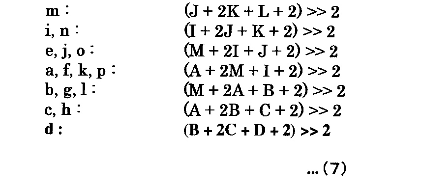
モード4は、Diagonal_Down_Right予測であり、図6に示す画素データA,B,C,D,I,J,K,L,Mの全てが上記「利用可能」である場合に適用される。
この場合に、イントラ予測回路43は、ブロックBLOCKの画素データa〜pの予測値を、画素データA,B,C,D,I,J,K,L,Mを用いて図7および下記(7)のように生成する。
Mode 4:
In this case, the
モード5:
モード5は、Diagonal_Vertical_Right予測であり、図6に示す画素データA,B,C,D,I,J,K,L,Mの全てが上記「利用可能」である場合に適用される。
この場合に、イントラ予測回路43は、ブロックBLOCKの画素データa〜pの予測値を、画素データA,B,C,D,I,J,K,L,Mを用いて図7および下記(8)のように生成する。
Mode 5:
In this case, the
モード6:
モード6は、Horizontal_Down予測であり、図6に示す画素データA,B,C,D,I,J,K,L,Mの全てが上記「利用可能」である場合に適用される。
この場合に、イントラ予測回路43は、ブロックBLOCKの画素データa〜pの予測値を、画素データA,B,C,D,I,J,K,L,Mを用いて図7および下記(9)のように生成する。
Mode 6:
In this case, the
モード7:
モード7は、Vertical_Left予測であり、図6に示す画素データA,B,C,D,I,J,K,L,Mの全てが上記「利用可能」である場合に適用される。
この場合に、イントラ予測回路43は、ブロックBLOCKの画素データa〜pの予測値を、画素データA,B,C,D,I,J,K,L,Mを用いて図7および下記(10)のように生成する。
Mode 7:
In this case, the
モード8:
モード8は、Horizontal_Up予測であり、図6に示す画素データA,B,C,D,I,J,K,L,Mの全てが上記「利用可能」である場合に適用される。
この場合に、イントラ予測回路43は、ブロックBLOCKの画素データa〜pの予測値を、画素データA,B,C,D,I,J,K,L,Mを用いて図7および下記(11)のように生成する。
Mode 8:
In this case, the
以下、イントラ予測回路43の構成について説明する。
図8は、図2に示すイントラ予測回路43の構成図である。
図8に示すように、イントラ予測回路43は、例えば、予測モード決定有無判断回路51、MPM選択回路52、予測モード指定データ・符号量生成回路53、4x4COST算出回路54、16x16COST算出回路55、予測モード決定回路56および予測モード指定データ再生成回路57を有する。
本実施形態では、4x4のブロックデータを単位として、図8に示す構成要素の全部あるいは一部の処理をパイプライン処理によって実現する。
以下、図8に示す各構成要素について説明する。
Hereinafter, the configuration of the
FIG. 8 is a block diagram of the
As illustrated in FIG. 8, the
In the present embodiment, all or some of the components shown in FIG. 8 are realized by pipeline processing in units of 4 × 4 block data.
Hereinafter, each component shown in FIG. 8 will be described.
予測モード決定有無判断回路51:
予測モード決定有無判断回路51は、原画像データS23内の処理対象のマクロブロックMB内の処理対象の4x4のブロックデータ(ブロックBLOCK)のアドレスを基に、当該処理対象のブロックデータが図3および図9(A)に示す「0」,「2」,「4」,「6」,「8」,「10」,「12」,「14」を要素とする第1のグループと、図3および図9(B)に示す「1」,「3」,「5」,「7」,「9」,「11」,「13」,「15」を要素とする第2のグループとの何れに属するかを判断する。
予測モード決定有無判断回路51は、上記判断の結果を示す判断結果信号S51をMPM選択回路52に出力する。
上記第1のグループと第2のグループを規定した趣旨は以下の通りである。
すなわち、MPM選択回路52においては、例えば、図10に示すブロックデータCを処理対象とすると、ブロックデータCに2次元画像水平方向で隣接し且つ処理対象として前に選択されるブロックデータAと、ブロックデータCに2次元画像垂直方向で隣接し且つ処理対象として前に選択されるブロックデータBとを予め決められた周囲のブロックデータとして用いて、これらに対して決定されたイントラ予測モードを基に、MPM(Most
Probable Mode)データが特定される。
ここで、マクロブロックMB内で4x4のブロックデータが処理対象として選択される順序は図3で示される。
Prediction mode determination presence / absence determination circuit 51:
The prediction mode determination presence /
The prediction mode determination presence /
The purpose of defining the first group and the second group is as follows.
That is, in the
Probable Mode) data is specified.
Here, the order in which 4 × 4 block data is selected as a processing target in the macroblock MB is shown in FIG.
ここで、図9(A)に示す第1のグループに属するブロックデータに対応した上記予め決められたブロックデータは、当該ブロックデータよりも2段階以上前にパイプライン処理が行われる。従って、第1グループに属するブロックデータの処理を開始するタイミングで、それに対応した上記予め決められたブロックデータのイントラ予測モードは既に決定されている。
例えば、図9(A)に示す「6」番目に選択されるブロックデータに対応した上記予め決められたブロックデータは「3」および「4」番目に選択され、「6」番目に選択されるブロックデータよりも2および3段階前にパイプライン処理が行われる。
一方、第2のグループに属するブロックデータに対応した上記予め決められたブロックデータには、当該ブロックデータの直前にパイプライン処理が行われるものがある。従って、第2グループに属するブロックデータの処理を開始するタイミングで、それに対応した上記予め決められたブロックデータのイントラ予測モードは未決定の場合がある。
例えば、図9(B)に示す「3」番目に選択されるブロックデータに対応した上記予め決められたブロックデータは、「1」および「2」番目に選択され、当該「3」番目に選択されるブロックデータよりも1および2段階前にパイプライン処理が行われる。
従って、「3」番目に選択されるブロックデータのMPMデータを決定するタイミングで、「2」番目に選択されるブロックデータのイントラ予測モードが未決定の場合がある。
Here, the predetermined block data corresponding to the block data belonging to the first group shown in FIG. 9A is subjected to pipeline processing at least two stages before the block data. Therefore, at the timing when processing of block data belonging to the first group is started, the predetermined intra prediction mode of the block data corresponding thereto is already determined.
For example, the predetermined block data corresponding to the “6” th block data selected in FIG. 9A is selected as the “3” and “4” th, and is selected as the “6” th. Pipeline processing is performed two and three stages before block data.
On the other hand, some of the predetermined block data corresponding to the block data belonging to the second group are subjected to pipeline processing immediately before the block data. Accordingly, there is a case where the predetermined intra prediction mode of block data corresponding to the block data belonging to the second group is not yet determined at the timing of starting processing.
For example, the predetermined block data corresponding to the block data selected “3” shown in FIG. 9B is selected “1” and “2”, and is selected “3”. Pipeline processing is performed one and two stages before the block data to be processed.
Accordingly, there is a case where the intra prediction mode of the block data selected as the “2” is not yet determined at the timing of determining the MPM data of the block data selected as the “3”.
MPM選択回路52:
MPM選択回路52は、予測モード決定有無判断回路51から入力した判断結果信号S51が「処理対象のブロックデータが第1のグループに属する」ことを示す場合に、処理対象として選択された4x4のブロックデータ(図10の「C」)に対して2次元画像の垂直方向で隣接し当該選択されたブロックデータによりも前に予測モード決定回路56においてイントラ予測モードが決定される第1のブロック(図10の「B」)と、前記選択されたブロックデータに対して2次元画像の水平方向で隣接し当該選択されたブロックデータよりも前に予測モード決定回路56においてイントラ予測モードが決定される第2のブロック(図10の「A」)とについて既に決定されたイントラ予測モードを基に、MPMデータS52を生成する。
具体的には、MPM選択回路52は、上記第1のブロックおよび第2のブロックのイントラ予測モードのうち、モード番号が小さいイントラ予測モードを示すMPMデータを生成する。
例えば、図10に示す4x4のブロックデータCが第1のグループに属し処理対象のブロックデータである場合に、そのMPMデータS52が示すイントラ予測モードMPM(C)は、下記式(12)のように生成される。
MPM selection circuit 52:
The
Specifically, the
For example, when the 4 × 4 block data C shown in FIG. 10 belongs to the first group and is the processing target block data, the intra prediction mode MPM (C) indicated by the MPM data S52 is expressed by the following equation (12). Is generated.
〔数12〕
MPM(C)=min(イントラ予測モード(A),イントラ予測モード(B))
…(12)
[Equation 12]
MPM (C) = min (intra prediction mode (A), intra prediction mode (B))
(12)
MPM選択回路52は、予測モード決定有無判断回路51から入力した判断結果信号S51が「処理対象のブロックデータが第2のグループに属する」ことを示す場合に、上記第2のブロックに対して2次元画像の水平方向で隣接し当該第2のブロックよりも前に予測モード決定回路56においてイントラ予測モードが決定される第3ブロックを、上記第2のブロックの代わりに予め決められたブロックとして用いて、選択さた処理対象のブロックデータのMPMデータS52を生成する。
例えば、図11に示す4x4のブロックデータCが第2のグループに属し処理対象のブロックデータである場合に、そのMPMデータS52は、上記第3のブロックA’のイントラ予測モードを用いて、下記式(13)のように生成される。
When the determination result signal S51 input from the prediction mode determination presence /
For example, when the 4 × 4 block data C shown in FIG. 11 belongs to the second group and is the block data to be processed, the MPM data S52 uses the intra prediction mode of the third block A ′ as described below. It is generated as in equation (13).
〔数13〕
MPM(C)=min(イントラ予測モード(A’),イントラ予測モード(B))
…(13)
[Equation 13]
MPM (C) = min (intra prediction mode (A ′), intra prediction mode (B))
... (13)
その他、MPM選択回路52は、予測モード決定有無判断回路51から入力した判断結果信号S51が「処理対象のブロックデータが第2のグループに属する」ことを示す場合に、上記第2のブロックに対して2次元画像の水平方向で隣接し当該第2のブロックよりも前に前記予測モードが決定される第3ブロックと上記第1のブロックに対して2次元画像の水平方向で隣接し当該第1のブロックよりも前に予測モード決定回路56においてイントラ予測モードが決定される第4ブロックとを基にイントラ予測モードを選択し、当該選択したイントラ予測モードと、上記第1のブロックについて決定されたイントラ予測モードとを基に、上記選択されたブロックのMPMデータS52を生成してもよい。
例えば、図11に示す4x4のブロックデータCが第2のグループに属し処理対象のブロックデータである場合に、そのMPMデータS52を下記式(14)のように生成する。
下記式(14)において、A’が上記第3のブロックに対応し、B’が上記第4のブロックに対応している。
In addition, when the determination result signal S51 input from the prediction mode determination presence /
For example, when the 4 × 4 block data C shown in FIG. 11 belongs to the second group and is the processing target block data, the MPM data S52 is generated as shown in the following equation (14).
In the following formula (14), A ′ corresponds to the third block, and B ′ corresponds to the fourth block.
〔数14〕
MPM(C)=min(MPM(イントラ予測モード(A’),イントラ予測モード(B’)),イントラ予測モード(B))
…(14)
[Formula 14]
MPM (C) = min (MPM (intra prediction mode (A ′), intra prediction mode (B ′)), intra prediction mode (B))
... (14)
予測モード指定データ・符号量生成回路53:
予測モード指定データ・符号量生成回路53は、MPM選択回路52から入力したMPMデータS52を基に、処理対象のブロックデータのヘッダデータ、並びにそのヘッダデータを符号化した場合の符号量を判断する指標となる指標データSATD0を生成する。
上記ヘッダデータには、最終的に決定されたイントラ予測モードを指定するための予測モード指定データPREV,REMが含まれる。
Prediction mode designation data / code amount generation circuit 53:
Based on the MPM data S52 input from the
The header data includes prediction mode designation data PREV and REM for designating the finally determined intra prediction mode.
図12は、予測モード指定データ・符号量生成回路53の処理を説明するためのフローチャートである。
ステップST1:
予測モード指定データ・符号量生成回路53は、図4〜図7を用いて説明したモード0〜8の9個のイントラ予測モードのうち未処理のイントラ予測モードを選択する。
ステップST2:
予測モード指定データ・符号量生成回路53は、MPM選択回路52から入力したMPMデータS52が示すイントラ予測モードと、ステップST1で選択したイントラ予測モードとが一致しているか否かを判断する。
予測モード指定データ・符号量生成回路53は、上記判断において一致していると判断した場合に、ステップST3に進み、そうでない場合にはステップST4に進む。
FIG. 12 is a flowchart for explaining the processing of the prediction mode designation data / code
Step ST1:
The prediction mode designation data / code
Step ST2:
The prediction mode designation data / code
The prediction mode designation data / code
ステップST3:
予測モード指定データ・符号量生成回路53は、予測モード指定データPREVに第1の論理値(例えば、論理値「1」)を設定する。
この場合に、予測モード指定データ・符号量生成回路53は、予測モード指定データREMには、1ビットのデフォルトの値を設定する。
また、予測モード指定データ・符号量生成回路53は、予測モード指定データREMを用いなくてもよい。すなわち、データ量「0」としてもよい。
Step ST3:
The prediction mode designation data / code
In this case, the prediction mode designation data / code
Further, the prediction mode designation data / code
ステップST4:
予測モード指定データ・符号量生成回路53は、予測モード指定データPREVに第2の論理値(例えば、論理値「0」)を設定する。
ステップST5:
予測モード指定データ・符号量生成回路53は、ステップST1で選択したイントラ予測モードのモード番号が、MPM選択回路52から入力したMPMデータS52が示すイントラ予測モードのモード番号に比べて小さいか否かを判断し、小さいと判断した場合にステップST6に進み、そうでない場合にはステップST7に進む。
Step ST4:
The prediction mode designation data / code
Step ST5:
The prediction mode designation data / code
ステップST6:
予測モード指定データ・符号量生成回路53は、ステップST1で選択したイントラ予測モードのモード番号を予測モード指定データREMに設定する。
ステップST7:
予測モード指定データ・符号量生成回路53は、ステップST1で選択したイントラ予測モードのモード番号から「1」を減算した番号を予測モード指定データREMに設定する。
ステップST8:
予測モード指定データ・符号量生成回路53は、全てのイントラ予測モードについてステップST1の選択を行ったか否かを判断し、行ったと判断するとステップST9に進み、そうでない場合にはステップST1に戻る。
ステップST9:
予測モード指定データ・符号量生成回路53は、上述した処理を経て得られた全ての予測モード指定データPREV,REMの予測符号量を生成し、これを4x4COST算出回路54に出力する。
Step ST6:
The prediction mode designation data / code
Step ST7:
The prediction mode designation data / code
Step ST8:
The prediction mode designation data / code
Step ST9:
The prediction mode designation data / code
4x4COST算出回路54は、図4〜図7を用いて説明したモード0〜8の9個のイントラ予測モードの各々について、下記式(15)に基づいて、符号量を予測する指標となる指標データCOSTiを生成する。
The 4 × 4
〔数15〕
COSTi=SATD+λ(QP)×SATD0
…(15)
[Equation 15]
COSTi = SATD + λ (QP) × SATD0
... (15)
上記式(4)において、SATDは、図6および図7を用いて説明した予測値によって構成される4x4の予測ブロックデータと、処理対象の4x4のブロックデータとの画素データ間の差分にアダマール変換を施した値の累積値である。
λ(QP)は、レート制御回路32から入力した量子化スケールに対応した量子化パラメータQPに応じて決まるヘッダデータの予測符号量の係数である。
SATD0は、予測モード指定データ・符号量生成回路53から入力した予測モード指定データPREV,REMの予測符号量を示している。
In the above equation (4), the SATD is a Hadamard transform into the difference between the pixel data of the 4 × 4 predicted block data composed of the predicted values described with reference to FIGS. 6 and 7 and the 4 × 4 block data to be processed. It is the cumulative value of the values that have been subjected to.
λ (QP) is a coefficient of the prediction code amount of header data determined according to the quantization parameter QP corresponding to the quantization scale input from the
SATD0 indicates the prediction code amount of the prediction mode specification data PREV and REM input from the prediction mode specification data / code
4x4COST算出回路54は、図4〜図7を用いて説明したモード0〜8の9個のイントラ予測モードの各々にいて生成した指標データCOSTiを予測モード決定回路56に出力する。
The 4 × 4
16x16COST算出回路55は、原画像データS23内の16x16画素を単位としたブロックデータについて予め規定された複数のイントラ予測モードの各々を基に、その予測符号量の指標となる指標データCOSTiを生成し、これを予測モード決定回路56に出力する。
本実施形態では、16x16のイントラ予測モードとして、例えば、垂直予測、水平予測、DC予測、プレイン予測の4モードが規定されている。
The 16 × 16
In the present embodiment, for example, four modes of vertical prediction, horizontal prediction, DC prediction, and plain prediction are defined as 16 × 16 intra prediction modes.
予測モード決定回路56は、4x4COST算出回路54および16x16COST算出回路55から入力した指標データCOSTiのうち最小の(符号化効率が最も高いと予測される)指標データCOSTiを特定し、それに対応したイントラ予測モードを、処理対象のブロックデータのイントラ予測モードとして決定する。
予測モード決定回路56は、処理対象のブロックデータのイントラ予測モードとして、4x4のイントラ予測モードを決定した場合に、それに対応して予測モード指定データ・符号量生成回路53が生成した予測モード指定データPREV,REMを予測モード指定データ再生成回路57に出力する。
また、予測モード決定回路56は、上記決定した4x4のイントラ予測モードに対応した指標データCOSTi、並びにその予測画像データPIiを図2に示す選択回路44に出力する。
また、予測モード決定回路56は、処理対象のブロックデータのイントラ予測モードとして、16x16のイントラ予測モードを決定した場合に、選択回路44からイントラ予測が選択されたことを示す選択信号S44を入力すると、当該決定したイントラ予測モードを示すIPMを図2に示す可逆符号化回路27に出力する。
また、予測モード決定回路56は、上記決定した16x16のイントラ予測モードに対応した指標データCOSTi、並びにその予測画像データPIiを図2に示す選択回路44に出力する。
The prediction
When the 4 × 4 intra prediction mode is determined as the intra prediction mode of the block data to be processed, the prediction
Further, the prediction
Further, when the 16 × 16 intra prediction mode is determined as the intra prediction mode of the block data to be processed, the prediction
Further, the prediction
予測モード指定データ再生成回路57は、その処理を開始するタイミングで、処理対象のブロックデータについて上記予め規定された他のブロックデータのイントラ予測モードが予測モード決定回路56において既に決定されているため、それらを基に、上述したMPM選択回路52の処理と同様の処理を行って、予測モード指定データPREV,REMを再生成する。
予測モード指定データ再生成回路57は、選択回路44からイントラ予測が選択されたことを示す選択信号S44を入力すると、予測モード指定データPREV,REMを図2に示す可逆符号化回路27に出力する。
The prediction mode designating
When receiving the selection signal S44 indicating that intra prediction is selected from the
以下、図8に示すイントラ予測回路43の動作例を説明する。
先ず、予測モード決定有無判断回路51が、原画像データS23内の処理対象のマクロブロックMB内の処理対象の4x4のブロックデータ(ブロックBLOCK)のアドレスを基に、当該ブロックデータが図9(A),(B)に示す第1のグループおよび第2のグループの何れに属するかを判断し、その判断結果を示す判断結果信号S51をMPM選択回路52に出力する。
Hereinafter, an operation example of the
First, the prediction mode determination presence /
次に、MPM選択回路52が、判断結果信号S51を基に、上述したようにMPMデータS52を生成し、これを予測モード指定データ・符号量生成回路53に出力する。
次に、予測モード指定データ・符号量生成回路53において、処理対象の4x4ブロックデータの予測モード指定データPREV,REMおよびその予測符号量を生成し、これを予測モード指定データ・符号量生成回路53に出力する。
次に、4x4COST算出回路54において、処理対象の4x4ブロックデータの指標データCOSTiを生成し、これを予測モード決定回路56に出力する。
また、16x16COST算出回路55において、処理対象の16x16ブロックデータの指標データCOSTiを生成し、これを予測モード決定回路56に出力する。
次に、予測モード決定回路56において、処理対象のブロックデータのイントラ予測モードが決定される。
このとき、4x4のイントラ予測モードが決定されると、その予測モード指定データPREV,REMが予測モード指定データ再生成回路57で再生成される。
Next, the
Next, the prediction mode designation data / code
Next, the 4 × 4
Further, the 16 × 16
Next, the prediction
At this time, when the 4 × 4 intra prediction mode is determined, the prediction mode designation data PREV and REM are regenerated by the prediction mode designation
以下、選択回路44について説明する。
選択回路44は、イントラ予測回路43から入力した指標データCOSTiと、動き予測・補償回路41から入力した指標データCOSTmとを比較する。
そして、選択回路44は、上記比較によりイントラ予測回路43から入力した指標データCOSTiの方が小さいと判断すると、イントラ予測回路43から入力した予測画像データPIiを選択して予測画像データPIとして演算回路24に出力する。また、選択回路44は、イントラ予測を選択したことを示す選択信号S44をイントラ予測回路43に出力する。
また、選択回路44は、上記比較により動き予測・補償回路41から入力した指標データCOSTmの方が小さいと判断すると、動き予測・補償回路41から入力した予測画像データPImを予測画像データPIとして選択して演算回路24に出力する。また、選択回路44は、動く予測・補償を選択したことを示す選択信号S44を動き予測・補償回路41に出力する。
Hereinafter, the
The
If the
When the
以下、図2に示す符号化装置2の全体動作を説明する。
入力となる画像信号は、まず、A/D変換回路22においてデジタル信号に変換される。 次に、出力となる画像圧縮情報のGOP構造に応じ、画面並べ替え回路23においてフレーム画像データの並べ替えが行われ、それによって得られた原画像データS23が演算回路24、イントラ予測回路43および動き予測・補償回路41に出力される。
次に、演算回路24が、画面並べ替え回路23からの原画像データS23と選択回路44からの予測画像データPIとの差分を検出し、その差分を示す画像データS24を直交変換回路25に出力する。
Hereinafter, the overall operation of the
The input image signal is first converted into a digital signal by the A /
Next, the
次に、直交変換回路25が、画像データS24に離散コサイン変換やカルーネン・レーベ変換等の直交変換を施して画像データS25を生成し、これを量子化回路26に出力する。
次に、量子化回路26が、画像データS25を量子化し、量子化された変換係数S26を可逆符号化回路27および逆量子化回路29に出力する。
次に、逆量子化回路29が、量子化回路26から入力した変換係数S26を逆量子化し、逆量子化した変換係数を示す画像データを逆直交変換回路30に出力する。
次に、逆直交変換回路30が、逆量子化回路29から入力した画像データに、直交変換回路25における直交変換の逆変換を施して生成した画像データを加算回路33に出力する。
次に、加算回路33が、逆直交変換回路30から入力した画像データと、選択回路44から入力した予測画像データPIとを加算して再構成画像データを生成し、これをデブロックフィルタ34に出力する。
デブロックフィルタ34は、加算回路33から入力した再構成画像データのブロック歪みを除去した画像データを、参照画像データとしてフレームメモリ31に書き込む。
Next, the
Next, the
Next, the
Next, the inverse
Next, the
The
そして、動き予測・補償回路41は、フレームメモリ31に記憶された参照画像データREFを基に、処理対象のブロックデータの動きベクトルMVを生成し、その指標データCOSTmと予測画像データPImとを選択回路44に出力する。
Then, the motion prediction /
また、イントラ予測回路43は、図8を用いて説明したように、イントラ予測を行い、それによって得た指標データCOSTiと予測画像データPIiとを選択回路44に出力する。
Further, as described with reference to FIG. 8, the
次に、選択回路44は、イントラ予測回路43から入力した指標データCOSTiと、動き予測・補償回路41から入力した指標データCOSTmとを比較する。
そして、選択回路44は、上記比較によりイントラ予測回路43から入力した指標データCOSTiの方が小さいと判断すると、イントラ予測回路43から入力した予測画像データPIiを選択して予測画像データPIとしえ演算回路24に出力する。また、選択回路44は、イントラ予測を選択したことを示す選択信号S44をイントラ予測回路43に出力する。
また、選択回路44は、上記比較により動き予測・補償回路41から入力した指標データCOSTmの方が小さいと判断すると、動き予測・補償回路41から入力した予測画像データPImを予測画像データPIとして選択して演算回路24に出力する。また、選択回路44は、動く予測・補償を選択したことを示す選択信号S44を動き予測・補償回路41に出力する。
以上説明したように、符号化装置2では、図8を用いて説明したように、MPM選択回路52において、処理対象のブロックデータの周囲の予め決められたブロックデータについて予測モード決定回路56によるイントラ予測モードが未決定である場合でも、その周囲の他のブロックデータの既に決定しているイントラ予測モードを基に、MPMデータS52を擬似的に生成する。そのため、予測モード指定データ・符号量生成回路53において、予測モード指定データPREV,REMの予測符号量を生成でき、4x4COST算出回路54における指標データCOSTiを擬似的に生成できる。
また、上記MPMデータS52は、上記予め決められたブロックデータに隣接したブロックデータのイントラ予測モードを用いるため、信頼性が高い。
これにより、予測モード決定回路56において、符号化効率が高い、イントラ予測モードを正確に決定できる。
Next, the
Then, when the
When the
As described above, in the
The MPM data S52 is highly reliable because it uses an intra prediction mode of block data adjacent to the predetermined block data.
Thereby, in the prediction
<第2実施形態>
上述した実施形態では、4x4のイントラ予測モードにおいて、4x4のブロックデータを単位としてパイプライン処理を行う場合を例示したが、本実施形態では、16x16のマクロブロックを単位として図8に示す全てあるいは一部の構成要素の処理をパイプライン処理で行う。
この場合に、図8に示すMPM選択回路52は、第1実施形態で説明した上記予め決められた4x4のブロックデータが、処理対象の4x4のブロックデータとは異なるマクロブロックに属し、当該マクロブロックについてMPM選択回路52がMPMデータS52を生成するタイミングで、予測モード決定回路56によるイントラ予測モードの決定が未決定のマクロブロックに属するブロックデータを上記予め決められたブロックデータとして用いる場合に、当該予め決められたブロックデータに代えて、既に予測モード決定回路56でイントラ予測モードが決定されている他のブロックデータのイントラ予測モードを用いる。
例えば、MPM選択回路52は、図9(A)に示すブロックデータ「0」,「2」,「8」,「10」を図10に示す処理対象のブロックデータCとした場合に、図10に示すブロックデータBのイントラ予測モードを示すMPMデータS52を生成する。
本実施形態によっても第1実施形態と同様の効果が得られる。
Second Embodiment
In the above-described embodiment, the case where pipeline processing is performed in units of 4 × 4 block data in the 4 × 4 intra prediction mode is illustrated. However, in the present embodiment, all or one shown in FIG. 8 is performed in units of 16 × 16 macroblocks. The processing of the constituent elements is performed by pipeline processing.
In this case, the
For example, when the block data “0”, “2”, “8”, “10” shown in FIG. 9A is set as the processing target block data C shown in FIG. MPM data S52 indicating the intra prediction mode of block data B shown in FIG.
According to this embodiment, the same effect as that of the first embodiment can be obtained.
本発明は上述した実施形態には限定されない。
例えば、上述した実施形態では、4x4のイントラ予測について、本発明を提供した場合を例示したが、それ以外のサイズのイントラ予測について本発明を提供してもよい。
The present invention is not limited to the embodiment described above.
For example, although the case where the present invention is provided for 4 × 4 intra prediction is illustrated in the above-described embodiment, the present invention may be provided for intra prediction of other sizes.
本発明は、画像データを符号化するシステムに適用可能である。 The present invention can be applied to a system for encoding image data.
1…通信システム、2…符号化装置、3…復号装置、22…A/D変換回路、23…画面並べ替え回路、24…演算回路、25…直交変換回路、26…量子化回路、27…可逆符号化回路、28…バッファ、29…逆量子化回路、30…逆直交変換回路、31…フレームメモリ、32…レート制御回路、33…加算回路、34…デブロックフィルタ、41…動き予測・補償回路、43…イントラ予測回路、44…選択回路、51…予測モード決定有無判断回路、52…MPM選択回路、53…予測モード指定データ・符号量生成回路、54…4x4COST算出回路、55…16x16COST算出回路、56…予測モード決定回路、57…予測モード指定データ再生成回路
DESCRIPTION OF
Claims (11)
前記選択されたブロック以外の予め決められたブロックの前記第1の予測モードが既に決定されているか否かを判断する判断手段と、
前記予め決められたブロックの前記第1の予測モードが既に決定されていると前記判断手段が判断した場合に、前記予め決められた前記ブロックの前記第1の予測モードを基に、前記選択したブロックに対して決定される前記第1の予測モードを指定するための予測モード指定データを生成するために用いられる第2の前記予測モードを特定し、前記予め決められた前記ブロックの前記第1の予測モードが未決定であると前記判断手段が判断した場合に、前記予め決められた前記ブロック以外のブロックの既に決定された前記第1の予測モードを基に、前記第2の予測モードを特定する予測モード特定手段と、
前記複数の予測モードの各々について、当該予測モードが前記選択されたブロックの前記第1の予測モードとして決定された場合の前記予測モード指定データの予測符号量を、前記予測モード特定手段が特定した前記第2の予測モードを基に決定する符号量決定手段と、
前記選択したブロックについて、前記複数の予測モードのうち符号化効率が所定の基準を満たす前記第1の予測モードを、前記符号量決定手段が決定した前記予測符号量を基に決定する予測モード決定手段と
を有する画像処理装置。 Each of a plurality of blocks constituting the two-dimensional image is selected in a predetermined order, and the selected block is subjected to intra prediction based on pixel data of a block other than the block defined by the prediction mode, and An image processing apparatus that determines, as the first prediction mode of the selected block, the prediction mode in which the coding efficiency satisfies a predetermined criterion among prediction modes,
Determining means for determining whether the first prediction mode of a predetermined block other than the selected block has already been determined;
When the determination unit determines that the first prediction mode of the predetermined block has already been determined, the selection is made based on the first prediction mode of the predetermined block. Identifying a second prediction mode used to generate prediction mode designating data for designating the first prediction mode determined for a block, and determining the first of the predetermined block When the determination unit determines that the prediction mode is not yet determined, the second prediction mode is determined based on the already determined first prediction mode of a block other than the predetermined block. A prediction mode identification means to identify;
For each of the plurality of prediction modes, the prediction mode specifying unit specifies the prediction code amount of the prediction mode designation data when the prediction mode is determined as the first prediction mode of the selected block. Code amount determining means for determining based on the second prediction mode;
Prediction mode determination for determining the first prediction mode for which the coding efficiency among the plurality of prediction modes satisfies a predetermined criterion for the selected block based on the prediction code amount determined by the code amount determination unit And an image processing apparatus.
請求項1に記載の画像処理装置。 The code amount determination unit includes, for each of the plurality of prediction modes, information indicating a match when the prediction mode matches the second prediction mode specified by the prediction mode specifying unit, and includes information indicating the match If the prediction mode designation data that does not include the mode identification value is generated and does not match, the difference between the identification value of the prediction mode and the identification value of the second prediction mode, or the identification value of the prediction mode The image processing apparatus according to claim 1, wherein the prediction mode designation data including a value obtained by subtracting a predetermined value is generated.
請求項1に記載の画像処理装置。 The prediction mode determination means is further based on a prediction code amount of a difference between prediction image data obtained based on pixel data of a block other than the block defined by the prediction mode and block data of the selected block The image processing apparatus according to claim 1, wherein the first prediction mode is determined.
前記予め決められた前記ブロックは、前記選択されたブロックより前に、前記予測モード決定手段による前記第1の予測モードの決定が行われるブロックである
請求項1に記載の画像処理装置。 The processing of the determination unit, the prediction mode selection unit, the code amount determination unit, and the prediction mode determination unit for the plurality of blocks is executed by pipeline processing in units of the blocks,
The image processing apparatus according to claim 1, wherein the predetermined block is a block in which the first prediction mode is determined by the prediction mode determination unit before the selected block.
請求項4に記載の画像処理装置。 The prediction mode specifying means, when the determination means determines that the first prediction mode of the predetermined block has already been determined, for the selected block, A first block that is adjacent in the vertical direction and whose first prediction mode is determined before the selected block is adjacent to the selected block in the horizontal direction of the two-dimensional image and the selected block. The image processing apparatus according to claim 4, wherein a second block in which the first prediction mode is determined before the determined block is used as the predetermined block.
請求項5に記載の画像処理装置。 The prediction mode specifying means, when the determination means determines that the first prediction mode of the predetermined block has not yet been determined, The third block that is adjacent in the horizontal direction and in which the first prediction mode is determined before the second block is used as the predetermined block instead of the second block. The image processing apparatus described.
前記予測モード特定手段は、前記第2のブロックに対して前記2次元画像の水平方向で隣接し当該第2のブロックによりも前に前記第1の予測モードが決定される第3ブロックと、前記第1のブロックに対して前記2次元画像の水平方向で隣接し当該第1のブロックによりも前に前記第1の予測モードが決定される第4ブロックとを基に予測モードを選択し、当該選択した予測モードと、前記第1のブロックの予測モードとを基に、前記選択されたブロックの前記第2の予測モードを特定する
請求項5に記載の画像処理装置。 When the determination means determines that the prediction mode of the predetermined block has not yet been determined,
The prediction mode specifying means includes a third block that is adjacent to the second block in the horizontal direction of the two-dimensional image and in which the first prediction mode is determined before the second block; Selecting a prediction mode based on a fourth block adjacent to the first block in the horizontal direction of the two-dimensional image and determining the first prediction mode before the first block; The image processing apparatus according to claim 5, wherein the second prediction mode of the selected block is specified based on the selected prediction mode and the prediction mode of the first block.
請求項1に記載の画像処理装置。 The determination unit, the prediction mode selection unit, the code amount determination unit, and the prediction mode determination unit for the plurality of blocks are processed by a plurality of macros that constitute the two-dimensional image and are each composed of the plurality of blocks. The image processing apparatus according to claim 1, wherein the image processing apparatus is executed by pipeline processing in units of blocks.
請求項8に記載の画像処理装置。 The predetermined block belongs to the macroblock different from the selected block, and the prediction mode determination is performed at a timing when the prediction mode specifying unit specifies the second prediction mode for the macroblock. When the block belonging to the macro block that has not been determined by the means becomes the predetermined block, the first prediction mode has already been replaced with the predetermined block. The image processing apparatus according to claim 8, wherein the first prediction mode of another block for which is determined is used.
前記画像処理装置は、
前記選択されたブロックについて前記予測モード決定手段が決定した前記第1の予測モードによって規定される当該ブロック以外のブロックの画素データを基に得られる予測画像データと前記選択されたブロックのブロックデータとの差分と、前記符号量決定手段が生成した前記予測モード指定データとを符号化する符号化手段
をさらに有する
請求項1に記載の画像処理装置。 The code amount determination means generates the prediction mode designation data,
The image processing apparatus includes:
Prediction image data obtained based on pixel data of a block other than the block defined by the first prediction mode determined by the prediction mode determination means for the selected block, and block data of the selected block; The image processing apparatus according to claim 1, further comprising: an encoding unit that encodes the difference between the two and the prediction mode designation data generated by the code amount determination unit.
前記選択されたブロック以外の予め決められたブロックの前記第1の予測モードが既に決定されているか否かを判断する第1の工程と、
前記予め決められたブロックの前記第1の予測モードが既に決定されていると前記第1の工程で判断した場合に、前記予め決められた前記ブロックの前記第1の予測モードを基に、前記選択したブロックに対して決定される前記第1の予測モードを指定するための予測モード指定データを生成するために用いられる第2の前記予測モードを特定し、前記予め決められた前記ブロックの前記第1の予測モードが未だ決定されていないと前記第1の工程で判断した場合に、前記予め決められた前記ブロック以外のブロックの既に決定された前記第1の予測モードを基に、前記第2の予測モードを特定する第2の工程と、
前記複数の予測モードの各々について、当該予測モードが前記選択されたブロックの前記第1の予測モードとして決定された場合の前記予測モード指定データの予測符号量を、前記第2の工程で特定した前記第2の予測モードを基に決定する第3の工程と、
前記選択したブロックについて、前記複数の予測モードのうち符号化効率が所定の基準を満たす前記第1の予測モードを、前記第3の工程で決定した前記予測符号量を基に決定する第4の工程と
を有する画像処理方法。
Each of a plurality of blocks constituting the two-dimensional image is selected in a predetermined order, and the selected block is subjected to intra prediction based on pixel data of a block other than the block defined by the prediction mode, and An image processing method for determining, as a first prediction mode of the selected block, the prediction mode in which an encoding efficiency among prediction modes satisfies a predetermined criterion,
A first step of determining whether or not the first prediction mode of a predetermined block other than the selected block has already been determined;
When it is determined in the first step that the first prediction mode of the predetermined block has already been determined, based on the first prediction mode of the predetermined block, Identifying a second prediction mode used to generate prediction mode designating data for designating the first prediction mode determined for the selected block, and the predetermined block of the block When it is determined in the first step that the first prediction mode has not yet been determined, the first prediction mode is determined based on the already determined first prediction mode of a block other than the predetermined block. A second step of identifying two prediction modes;
For each of the plurality of prediction modes, the prediction code amount of the prediction mode designation data when the prediction mode is determined as the first prediction mode of the selected block is specified in the second step. A third step of determining based on the second prediction mode;
For the selected block, a first prediction mode whose coding efficiency satisfies a predetermined criterion among the plurality of prediction modes is determined based on the prediction code amount determined in the third step. An image processing method comprising the steps of:
Priority Applications (1)
| Application Number | Priority Date | Filing Date | Title |
|---|---|---|---|
| JP2004176950A JP2006005438A (en) | 2004-06-15 | 2004-06-15 | Image processing apparatus and method |
Applications Claiming Priority (1)
| Application Number | Priority Date | Filing Date | Title |
|---|---|---|---|
| JP2004176950A JP2006005438A (en) | 2004-06-15 | 2004-06-15 | Image processing apparatus and method |
Publications (1)
| Publication Number | Publication Date |
|---|---|
| JP2006005438A true JP2006005438A (en) | 2006-01-05 |
Family
ID=35773481
Family Applications (1)
| Application Number | Title | Priority Date | Filing Date |
|---|---|---|---|
| JP2004176950A Pending JP2006005438A (en) | 2004-06-15 | 2004-06-15 | Image processing apparatus and method |
Country Status (1)
| Country | Link |
|---|---|
| JP (1) | JP2006005438A (en) |
Cited By (31)
| Publication number | Priority date | Publication date | Assignee | Title |
|---|---|---|---|---|
| WO2007116617A1 (en) * | 2006-04-10 | 2007-10-18 | Megachips Corporation | Image data generation method |
| JP2007288785A (en) * | 2006-04-13 | 2007-11-01 | Samsung Electronics Co Ltd | Image data spatial prediction apparatus and method, encoding apparatus and method using the same, image data spatial prediction compensation apparatus and method, and decoding apparatus and method using the same |
| WO2007129433A1 (en) * | 2006-04-17 | 2007-11-15 | Toshihiro Minami | Dynamic image encoding device and dynamic image encoding method |
| JP2008005545A (en) * | 2006-04-17 | 2008-01-10 | Toshihiro Minami | Moving picture coding apparatus and moving picture coding method |
| JP2009523395A (en) * | 2006-01-11 | 2009-06-18 | クゥアルコム・インコーポレイテッド | Video coding with fine granularity spatial scalability |
| JP2009177352A (en) * | 2008-01-22 | 2009-08-06 | Canon Inc | Moving picture coding apparatus, control method therefor, and computer program |
| EP2242275A1 (en) | 2009-04-14 | 2010-10-20 | Sony Corporation | Image encoding apparatus, image encoding method, and computer program |
| JP2010263301A (en) * | 2009-04-30 | 2010-11-18 | Mega Chips Corp | Image data generation method |
| JP2011041014A (en) * | 2009-08-11 | 2011-02-24 | Canon Inc | Device for encoding moving image, method of controlling the same, and program |
| WO2012081477A1 (en) * | 2010-12-17 | 2012-06-21 | ソニー株式会社 | Image processing device and method |
| WO2012096229A1 (en) * | 2011-01-13 | 2012-07-19 | ソニー株式会社 | Encoding device, encoding method, decoding device, and decoding method |
| WO2013048033A1 (en) * | 2011-09-28 | 2013-04-04 | 한국전자통신연구원 | Method and apparatus for encoding/decoding intra prediction mode |
| WO2013058520A1 (en) * | 2011-10-18 | 2013-04-25 | 엘지전자 주식회사 | Method for intra prediction and device therefor |
| WO2013085282A1 (en) * | 2011-12-05 | 2013-06-13 | 엘지전자 주식회사 | Method and device for intra prediction |
| US8605784B2 (en) | 2009-08-17 | 2013-12-10 | Samsung Electronics Co., Ltd. | Method and apparatus for encoding video, and method and apparatus for decoding video |
| JP2014507857A (en) * | 2011-01-14 | 2014-03-27 | シーメンス アクチエンゲゼルシヤフト | Method and apparatus for forming predictive values |
| KR101452195B1 (en) * | 2011-11-04 | 2014-10-23 | 인포브릿지 피티이 엘티디 | Method and apparatus of deriving intra prediction mode |
| JP2014530556A (en) * | 2011-10-24 | 2014-11-17 | インターコード プライベート リミテッド | Video decoding method and apparatus |
| WO2015093890A1 (en) * | 2013-12-19 | 2015-06-25 | 삼성전자 주식회사 | Video encoding method and device involving intra prediction, and video decoding method and device |
| CN104853210A (en) * | 2011-06-28 | 2015-08-19 | 三星电子株式会社 | Method for decoding video |
| JP2015179944A (en) * | 2014-03-19 | 2015-10-08 | 日本電信電話株式会社 | Intra prediction direction determination method and intra prediction direction determination program |
| JP2016042615A (en) * | 2014-08-13 | 2016-03-31 | 沖電気工業株式会社 | Video encoding apparatus, method and program |
| JP2016136700A (en) * | 2015-01-23 | 2016-07-28 | キヤノン株式会社 | Image coding apparatus, image coding method, and program |
| JP2016140090A (en) * | 2010-04-09 | 2016-08-04 | エレクトロニクス アンド テレコミュニケーションズ リサーチ インスチチュートElectronics And Telecommunications Research Institute | Intra prediction execution method and apparatus using adaptive filter |
| US9432675B2 (en) | 2011-09-28 | 2016-08-30 | Electronics And Telecommunications Research Institute | Method and apparatus for encoding/decoding intra prediction mode |
| WO2016153146A1 (en) * | 2015-03-23 | 2016-09-29 | 엘지전자(주) | Method for processing image on basis of intra prediction mode and apparatus therefor |
| CN107770535A (en) * | 2011-11-04 | 2018-03-06 | 杰尼普Pte有限公司 | The method for producing reconstructed blocks |
| KR101835834B1 (en) * | 2009-12-16 | 2018-04-19 | 한국전자통신연구원 | Method and apparatus for adaptive image decoding |
| CN108093260A (en) * | 2011-10-24 | 2018-05-29 | 英孚布瑞智有限私人贸易公司 | Reconstructed blocks creation method |
| CN108259907A (en) * | 2011-11-04 | 2018-07-06 | 英孚布瑞智有限私人贸易公司 | Image decoding apparatus |
| CN108391125A (en) * | 2011-11-07 | 2018-08-10 | 杰尼普Pte有限公司 | To the method and apparatus of video data decoding |
-
2004
- 2004-06-15 JP JP2004176950A patent/JP2006005438A/en active Pending
Cited By (154)
| Publication number | Priority date | Publication date | Assignee | Title |
|---|---|---|---|---|
| US8315308B2 (en) | 2006-01-11 | 2012-11-20 | Qualcomm Incorporated | Video coding with fine granularity spatial scalability |
| JP2009523395A (en) * | 2006-01-11 | 2009-06-18 | クゥアルコム・インコーポレイテッド | Video coding with fine granularity spatial scalability |
| WO2007116617A1 (en) * | 2006-04-10 | 2007-10-18 | Megachips Corporation | Image data generation method |
| JP2007288785A (en) * | 2006-04-13 | 2007-11-01 | Samsung Electronics Co Ltd | Image data spatial prediction apparatus and method, encoding apparatus and method using the same, image data spatial prediction compensation apparatus and method, and decoding apparatus and method using the same |
| US8218629B2 (en) | 2006-04-13 | 2012-07-10 | Samsung Electronics Co., Ltd. | Encoding and/or decoding system, medium, and method with spatial prediction and spatial prediction compensation of image data |
| WO2007129433A1 (en) * | 2006-04-17 | 2007-11-15 | Toshihiro Minami | Dynamic image encoding device and dynamic image encoding method |
| JP2007312340A (en) * | 2006-04-17 | 2007-11-29 | Toshihiro Minami | Video encoding device |
| JP2008005545A (en) * | 2006-04-17 | 2008-01-10 | Toshihiro Minami | Moving picture coding apparatus and moving picture coding method |
| JP2009177352A (en) * | 2008-01-22 | 2009-08-06 | Canon Inc | Moving picture coding apparatus, control method therefor, and computer program |
| EP2242275A1 (en) | 2009-04-14 | 2010-10-20 | Sony Corporation | Image encoding apparatus, image encoding method, and computer program |
| JP2010263301A (en) * | 2009-04-30 | 2010-11-18 | Mega Chips Corp | Image data generation method |
| US9516320B2 (en) | 2009-04-30 | 2016-12-06 | Megachips Corporation | Method of generating image data |
| JP2011041014A (en) * | 2009-08-11 | 2011-02-24 | Canon Inc | Device for encoding moving image, method of controlling the same, and program |
| US8989266B2 (en) | 2009-08-17 | 2015-03-24 | Samsung Electronics Co., Ltd. | Method and apparatus for encoding video, and method and apparatus for decoding video |
| US9374591B2 (en) | 2009-08-17 | 2016-06-21 | Samsung Electronics Co., Ltd. | Method and apparatus for encoding video, and method and apparatus for decoding video |
| US8605784B2 (en) | 2009-08-17 | 2013-12-10 | Samsung Electronics Co., Ltd. | Method and apparatus for encoding video, and method and apparatus for decoding video |
| JP2013255273A (en) * | 2009-08-17 | 2013-12-19 | Samsung Electronics Co Ltd | Method and apparatus for encoding video, and method and apparatus for decoding video |
| US9071839B2 (en) | 2009-08-17 | 2015-06-30 | Samsung Electronics Co., Ltd. | Method and apparatus for encoding video, and method and apparatus for decoding video |
| US9049458B2 (en) | 2009-08-17 | 2015-06-02 | Samsung Electronics Co., Ltd. | Method and apparatus for encoding video, and method and apparatus for decoding video |
| US9036703B2 (en) | 2009-08-17 | 2015-05-19 | Samsung Electronics Co., Ltd. | Method and apparatus for encoding video, and method and apparatus for decoding video |
| JP2014079012A (en) * | 2009-08-17 | 2014-05-01 | Samsung Electronics Co Ltd | Method and apparatus for encoding video, and method and apparatus for decoding video |
| US8787458B2 (en) | 2009-08-17 | 2014-07-22 | Samsung Electronics Co., Ltd. | Method and apparatus for encoding video, and method and apparatus for decoding video |
| KR102437751B1 (en) | 2009-12-16 | 2022-08-29 | 한국전자통신연구원 | Method and apparatus for adaptive image decoding |
| KR20200047493A (en) * | 2009-12-16 | 2020-05-07 | 한국전자통신연구원 | Method and apparatus for adaptive image decoding |
| KR102634646B1 (en) | 2009-12-16 | 2024-02-07 | 한국전자통신연구원 | Method and apparatus for adaptive image decoding |
| KR101933029B1 (en) * | 2009-12-16 | 2018-12-27 | 한국전자통신연구원 | Method and apparatus for adaptive image decoding |
| KR101946916B1 (en) * | 2009-12-16 | 2019-02-11 | 한국전자통신연구원 | Method and apparatus for adaptive image decoding |
| US11805243B2 (en) | 2009-12-16 | 2023-10-31 | Electronics And Telecommunications Research Institute | Adaptive image encoding device and method |
| KR20180082412A (en) * | 2009-12-16 | 2018-07-18 | 한국전자통신연구원 | Method and apparatus for adaptive image decoding |
| US11659159B2 (en) | 2009-12-16 | 2023-05-23 | Electronics And Telecommunications Research Institute | Adaptive image encoding device and method |
| KR20230066527A (en) * | 2009-12-16 | 2023-05-16 | 한국전자통신연구원 | Method and apparatus for adaptive image decoding |
| KR102528914B1 (en) | 2009-12-16 | 2023-05-03 | 한국전자통신연구원 | Method and apparatus for adaptive image decoding |
| KR20180082411A (en) * | 2009-12-16 | 2018-07-18 | 한국전자통신연구원 | Method and apparatus for adaptive image decoding |
| KR20180082413A (en) * | 2009-12-16 | 2018-07-18 | 한국전자통신연구원 | Method and apparatus for adaptive image decoding |
| KR20220123198A (en) * | 2009-12-16 | 2022-09-06 | 한국전자통신연구원 | Adaptive video encoding method and apparatus |
| KR20180082414A (en) * | 2009-12-16 | 2018-07-18 | 한국전자통신연구원 | Method and apparatus for adaptive image decoding |
| US12206843B2 (en) | 2009-12-16 | 2025-01-21 | Electronics And Telecommunications Research Institute | Adaptive video decoding and encoding method, and apparatus using same |
| KR20180082415A (en) * | 2009-12-16 | 2018-07-18 | 한국전자통신연구원 | Method and apparatus for adaptive image decoding |
| KR20210148039A (en) * | 2009-12-16 | 2021-12-07 | 한국전자통신연구원 | Method and apparatus for adaptive image decoding |
| US10419752B2 (en) | 2009-12-16 | 2019-09-17 | Electronics And Telecommunications Research Institute | Adaptive image encoding device and method |
| KR102332672B1 (en) | 2009-12-16 | 2021-12-01 | 한국전자통신연구원 | Method and apparatus for adaptive image decoding |
| KR102104585B1 (en) | 2009-12-16 | 2020-04-24 | 한국전자통신연구원 | Method and apparatus for adaptive image decoding |
| KR102219511B1 (en) | 2009-12-16 | 2021-02-24 | 한국전자통신연구원 | Method and apparatus for adaptive image decoding |
| KR20210020984A (en) * | 2009-12-16 | 2021-02-24 | 한국전자통신연구원 | Method and apparatus for adaptive image decoding |
| US10728541B2 (en) | 2009-12-16 | 2020-07-28 | Electronics And Telecommunications Research Institute | Adaptive image encoding device and method |
| US12212739B2 (en) | 2009-12-16 | 2025-01-28 | Electronics And Telecommunications Research Institute | Adaptive video encoding device and method, and appartus using same |
| US10708580B2 (en) | 2009-12-16 | 2020-07-07 | Electronics And Telecommunications Research Institute | Adaptive image encoding device and method |
| US11812012B2 (en) | 2009-12-16 | 2023-11-07 | Electronics And Telecommunications Research Institute | Adaptive image encoding device and method |
| KR101835834B1 (en) * | 2009-12-16 | 2018-04-19 | 한국전자통신연구원 | Method and apparatus for adaptive image decoding |
| KR102104582B1 (en) * | 2009-12-16 | 2020-04-24 | 한국전자통신연구원 | Method and apparatus for adaptive image decoding |
| KR102107091B1 (en) * | 2009-12-16 | 2020-05-06 | 한국전자통신연구원 | Method and apparatus for adaptive image decoding |
| KR102104583B1 (en) * | 2009-12-16 | 2020-04-24 | 한국전자통신연구원 | Method and apparatus for adaptive image decoding |
| KR102104584B1 (en) * | 2009-12-16 | 2020-04-24 | 한국전자통신연구원 | Method and apparatus for adaptive image decoding |
| US10440393B2 (en) | 2010-04-09 | 2019-10-08 | Electronics And Telecommunications Research Institute | Method and apparatus for performing intra-prediction using adaptive filter |
| US10440392B2 (en) | 2010-04-09 | 2019-10-08 | Electronics And Telecommunications Research Institute | Method and apparatus for performing intra-prediction using adaptive filter |
| JP2017143542A (en) * | 2010-04-09 | 2017-08-17 | エレクトロニクス アンド テレコミュニケーションズ リサーチ インスチチュートElectronics And Telecommunications Research Institute | Video coding device |
| US9661345B2 (en) | 2010-04-09 | 2017-05-23 | Electronics And Telecommunications Research Institute | Method and apparatus for performing intra-prediction using adaptive filter |
| US10951917B2 (en) | 2010-04-09 | 2021-03-16 | Electronics And Telecommunications Research Institute | Method and apparatus for performing intra-prediction using adaptive filter |
| US10623771B2 (en) | 2010-04-09 | 2020-04-14 | Electronics And Telecommunications Research Institute | Method and apparatus for performing intra-prediction using adaptive filter |
| US10623770B2 (en) | 2010-04-09 | 2020-04-14 | Electronics And Telecommunications Research Institute | Method and apparatus for performing intra-prediction using adaptive filter |
| US10623769B2 (en) | 2010-04-09 | 2020-04-14 | Electronics And Telecommunications Research Institute | Method and apparatus for performing intra-prediction using adaptive filter |
| US10560721B2 (en) | 2010-04-09 | 2020-02-11 | Electronics And Telecommunications Research Institute | Method and apparatus for performing intra-prediction using adaptive filter |
| US10560722B2 (en) | 2010-04-09 | 2020-02-11 | Electronics And Telecommunications Research Institute | Method and apparatus for performing intra-prediction using adaptive filter |
| US9781448B2 (en) | 2010-04-09 | 2017-10-03 | Electronics And Telecommunications Research Institute | Method and apparatus for performing intra-prediction using adaptive filter |
| US10432968B2 (en) | 2010-04-09 | 2019-10-01 | Electronics And Telecommunications Research Institute | Method and apparatus for performing intra-prediction using adaptive filter |
| US9838711B2 (en) | 2010-04-09 | 2017-12-05 | Electronics And Telecommunications Research Institute | Method and apparatus for performing intra-prediction using adaptive filter |
| US10075734B2 (en) | 2010-04-09 | 2018-09-11 | Electronics And Telecommunications Research Institute | Method and apparatus for performing intra-prediction using adaptive filter |
| JP2016140090A (en) * | 2010-04-09 | 2016-08-04 | エレクトロニクス アンド テレコミュニケーションズ リサーチ インスチチュートElectronics And Telecommunications Research Institute | Intra prediction execution method and apparatus using adaptive filter |
| US12075090B2 (en) | 2010-04-09 | 2024-08-27 | Electronics And Telecommunications Research Institute | Method and apparatus for performing intra-prediction using adaptive filter |
| US11601673B2 (en) | 2010-04-09 | 2023-03-07 | Electronics And Telecommunications Research Institute | Method and apparatus for performing intra-prediction using adaptive filter |
| WO2012081477A1 (en) * | 2010-12-17 | 2012-06-21 | ソニー株式会社 | Image processing device and method |
| WO2012096229A1 (en) * | 2011-01-13 | 2012-07-19 | ソニー株式会社 | Encoding device, encoding method, decoding device, and decoding method |
| US9225985B2 (en) | 2011-01-14 | 2015-12-29 | Siemens Aktiengesellschaft | Methods and devices for forming a prediction value |
| JP2014507857A (en) * | 2011-01-14 | 2014-03-27 | シーメンス アクチエンゲゼルシヤフト | Method and apparatus for forming predictive values |
| US9451260B2 (en) | 2011-06-28 | 2016-09-20 | Samsung Electronics Co., Ltd. | Method and apparatus for coding video and method and apparatus for decoding video, using intra prediction |
| CN104853210B (en) * | 2011-06-28 | 2017-05-03 | 三星电子株式会社 | Method for decoding video |
| US9473776B2 (en) | 2011-06-28 | 2016-10-18 | Samsung Electronics Co., Ltd. | Method and apparatus for coding video and method and apparatus for decoding video, using intra prediction |
| US9479783B2 (en) | 2011-06-28 | 2016-10-25 | Samsung Electronics Co., Ltd. | Method and apparatus for coding video and method and apparatus for decoding video, using intra prediction |
| US9485510B2 (en) | 2011-06-28 | 2016-11-01 | Samsung Electronics Co., Ltd. | Method and apparatus for coding video and method and apparatus for decoding video, using intra prediction |
| CN104853210A (en) * | 2011-06-28 | 2015-08-19 | 三星电子株式会社 | Method for decoding video |
| US9503727B2 (en) | 2011-06-28 | 2016-11-22 | Samsung Electronics Co., Ltd. | Method and apparatus for coding video and method apparatus for decoding video, accompanied with intra prediction |
| US12166975B2 (en) | 2011-09-28 | 2024-12-10 | Electronics And Telecommunications Research Institute | Method and apparatus for encoding/decoding intra prediction mode |
| US11729380B2 (en) | 2011-09-28 | 2023-08-15 | Electronics And Telecommunications Research Institute | Method and apparatus for encoding/decoding intra prediction mode |
| WO2013048033A1 (en) * | 2011-09-28 | 2013-04-04 | 한국전자통신연구원 | Method and apparatus for encoding/decoding intra prediction mode |
| US11252407B2 (en) | 2011-09-28 | 2022-02-15 | Electronics And Telecommunications Research Institute | Method and apparatus for encoding/decoding intra prediction mode |
| US9432675B2 (en) | 2011-09-28 | 2016-08-30 | Electronics And Telecommunications Research Institute | Method and apparatus for encoding/decoding intra prediction mode |
| US10091503B2 (en) | 2011-09-28 | 2018-10-02 | Electronics And Telecommunications Research Institute | Method and apparatus for encoding/decoding intra prediction mode |
| US12166976B2 (en) | 2011-09-28 | 2024-12-10 | Electronics And Telecommunications Research Institute | Method and apparatus for encoding/decoding intra prediction mode |
| US10652533B2 (en) | 2011-09-28 | 2020-05-12 | Electronics And Telecommunications Research Institute | Method and apparatus for encoding/decoding intra prediction mode |
| US11700394B2 (en) | 2011-10-18 | 2023-07-11 | Lg Electronics Inc. | Method for intra prediction and device therefor |
| US9848206B2 (en) | 2011-10-18 | 2017-12-19 | Lg Electronics Inc. | Method for intra prediction and device therefor |
| US10880574B2 (en) | 2011-10-18 | 2020-12-29 | Lg Electronics Inc. | Method for intra prediction and device therefor |
| US11991391B2 (en) | 2011-10-18 | 2024-05-21 | Lg Electronics Inc. | Method for intra prediction and device therefor |
| US10728577B2 (en) | 2011-10-18 | 2020-07-28 | Lg Electronics Inc. | Method for intra prediction and device therefor |
| US11750838B2 (en) | 2011-10-18 | 2023-09-05 | Lg Electronics Inc. | Method for intra prediction and device therefor |
| US10349082B2 (en) | 2011-10-18 | 2019-07-09 | Lg Electronics Inc. | Method for intra prediction and device therefor |
| US11102511B2 (en) | 2011-10-18 | 2021-08-24 | LG Electionics Inc. | Method for intra prediction and device therefor |
| WO2013058520A1 (en) * | 2011-10-18 | 2013-04-25 | 엘지전자 주식회사 | Method for intra prediction and device therefor |
| US9319683B2 (en) | 2011-10-18 | 2016-04-19 | Lg Electronics Inc. | Method for intra prediction and device therefor |
| US10334272B2 (en) | 2011-10-18 | 2019-06-25 | Lg Electronics Inc. | Method for intra prediction and device therefor |
| US11290744B2 (en) | 2011-10-18 | 2022-03-29 | Lg Electronics Inc. | Method for intra prediction and device therefor |
| CN108111848A (en) * | 2011-10-24 | 2018-06-01 | 英孚布瑞智有限私人贸易公司 | Picture decoding apparatus |
| CN108174213B (en) * | 2011-10-24 | 2022-07-12 | 占史克威尔有限公司 | Image decoding device |
| CN108093260A (en) * | 2011-10-24 | 2018-05-29 | 英孚布瑞智有限私人贸易公司 | Reconstructed blocks creation method |
| CN108093262B (en) * | 2011-10-24 | 2022-01-04 | 英孚布瑞智有限私人贸易公司 | Image decoding device |
| CN108093260B (en) * | 2011-10-24 | 2022-01-04 | 英孚布瑞智有限私人贸易公司 | Reconstruction block creation method |
| CN108093261B (en) * | 2011-10-24 | 2022-01-04 | 英孚布瑞智有限私人贸易公司 | Image decoding device |
| CN108093262A (en) * | 2011-10-24 | 2018-05-29 | 英孚布瑞智有限私人贸易公司 | Picture decoding apparatus |
| CN108093261A (en) * | 2011-10-24 | 2018-05-29 | 英孚布瑞智有限私人贸易公司 | Picture decoding apparatus |
| JP2014530556A (en) * | 2011-10-24 | 2014-11-17 | インターコード プライベート リミテッド | Video decoding method and apparatus |
| CN108111848B (en) * | 2011-10-24 | 2022-07-12 | 占史克威尔有限公司 | Image decoding device |
| CN108174213A (en) * | 2011-10-24 | 2018-06-15 | 英孚布瑞智有限私人贸易公司 | Picture decoding apparatus |
| CN108366260B (en) * | 2011-11-04 | 2020-10-16 | 英孚布瑞智有限私人贸易公司 | Apparatus for generating prediction block in intra prediction |
| CN108366260A (en) * | 2011-11-04 | 2018-08-03 | 英孚布瑞智有限私人贸易公司 | Equipment for generating prediction block in intra prediction |
| KR101452195B1 (en) * | 2011-11-04 | 2014-10-23 | 인포브릿지 피티이 엘티디 | Method and apparatus of deriving intra prediction mode |
| CN107087174B (en) * | 2011-11-04 | 2020-04-17 | 英孚布瑞智有限私人贸易公司 | Method and apparatus for deriving intra prediction mode |
| CN107770535A (en) * | 2011-11-04 | 2018-03-06 | 杰尼普Pte有限公司 | The method for producing reconstructed blocks |
| CN107087174A (en) * | 2011-11-04 | 2017-08-22 | 英孚布瑞智有限私人贸易公司 | The method and apparatus for deriving intra prediction mode |
| CN108259907A (en) * | 2011-11-04 | 2018-07-06 | 英孚布瑞智有限私人贸易公司 | Image decoding apparatus |
| CN108259907B (en) * | 2011-11-04 | 2021-09-03 | 英孚布瑞智有限私人贸易公司 | image decoding equipment |
| CN108347614B (en) * | 2011-11-04 | 2021-09-07 | 英孚布瑞智有限私人贸易公司 | Method for generating prediction blocks in intra prediction |
| CN104869409A (en) * | 2011-11-04 | 2015-08-26 | 英孚布瑞智有限私人贸易公司 | Method And Apparatus Of Deriving Intra Predicion Mode |
| CN107770535B (en) * | 2011-11-04 | 2020-07-14 | 英孚布瑞智有限私人贸易公司 | Method for generating reconstructed block |
| CN108347614A (en) * | 2011-11-04 | 2018-07-31 | 英孚布瑞智有限私人贸易公司 | Method for generating prediction block in intra prediction |
| CN108769702B (en) * | 2011-11-07 | 2021-09-03 | 英孚布瑞智有限私人贸易公司 | Method and apparatus for decoding video data |
| CN108391126A (en) * | 2011-11-07 | 2018-08-10 | 杰尼普Pte有限公司 | To the method and apparatus of video data decoding |
| CN108769703A (en) * | 2011-11-07 | 2018-11-06 | 英孚布瑞智有限私人贸易公司 | To the method and apparatus of video data decoding |
| CN108391125A (en) * | 2011-11-07 | 2018-08-10 | 杰尼普Pte有限公司 | To the method and apparatus of video data decoding |
| CN108769702A (en) * | 2011-11-07 | 2018-11-06 | 英孚布瑞智有限私人贸易公司 | To the method and apparatus of video data decoding |
| CN108650512A (en) * | 2011-11-07 | 2018-10-12 | 英孚布瑞智有限私人贸易公司 | To the method and apparatus of video data decoding |
| US10887605B2 (en) | 2011-12-05 | 2021-01-05 | Lg Electronics Inc. | Method and device for intra prediction |
| CN108184121A (en) * | 2011-12-05 | 2018-06-19 | Lg 电子株式会社 | The method and apparatus of intra prediction |
| US11375206B2 (en) | 2011-12-05 | 2022-06-28 | Lg Electronics Inc. | Method and device for intra prediction |
| US10368077B2 (en) | 2011-12-05 | 2019-07-30 | Lg Electronics Inc. | Method and device for intra prediction |
| CN108235008A (en) * | 2011-12-05 | 2018-06-29 | Lg 电子株式会社 | The method and apparatus of intra prediction |
| US11627326B2 (en) | 2011-12-05 | 2023-04-11 | Lg Electronics Inc. | Method and device for intra prediction |
| WO2013085282A1 (en) * | 2011-12-05 | 2013-06-13 | 엘지전자 주식회사 | Method and device for intra prediction |
| US11924441B2 (en) | 2011-12-05 | 2024-03-05 | Lg Electronics Inc. | Method and device for intra prediction |
| CN108174206A (en) * | 2011-12-05 | 2018-06-15 | Lg 电子株式会社 | The method and apparatus of intra prediction |
| US9554136B2 (en) | 2011-12-05 | 2017-01-24 | Lg Electronics Inc. | Method and device for intra prediction |
| US9866843B2 (en) | 2011-12-05 | 2018-01-09 | Lg Electronics Inc. | Method and device for intra prediction |
| CN108174205A (en) * | 2011-12-05 | 2018-06-15 | Lg 电子株式会社 | The method and apparatus of intra prediction |
| WO2015093890A1 (en) * | 2013-12-19 | 2015-06-25 | 삼성전자 주식회사 | Video encoding method and device involving intra prediction, and video decoding method and device |
| US10257538B2 (en) | 2013-12-19 | 2019-04-09 | Samsung Electronics Co., Ltd. | Video encoding method and device involving intra prediction, and video decoding method and device |
| JP2015179944A (en) * | 2014-03-19 | 2015-10-08 | 日本電信電話株式会社 | Intra prediction direction determination method and intra prediction direction determination program |
| JP2016042615A (en) * | 2014-08-13 | 2016-03-31 | 沖電気工業株式会社 | Video encoding apparatus, method and program |
| JP2016136700A (en) * | 2015-01-23 | 2016-07-28 | キヤノン株式会社 | Image coding apparatus, image coding method, and program |
| US10349050B2 (en) | 2015-01-23 | 2019-07-09 | Canon Kabushiki Kaisha | Image coding apparatus, image coding method and recording medium |
| US10880553B2 (en) | 2015-03-23 | 2020-12-29 | Lg Electronics Inc. | Method for processing image on basis of intra prediction mode and apparatus therefor |
| US10506238B2 (en) | 2015-03-23 | 2019-12-10 | Lg Electronics Inc. | Method for processing image on basis of intra prediction mode and apparatus therefor |
| WO2016153146A1 (en) * | 2015-03-23 | 2016-09-29 | 엘지전자(주) | Method for processing image on basis of intra prediction mode and apparatus therefor |
| US12028531B2 (en) | 2015-03-23 | 2024-07-02 | Lg Electronics Inc. | Method for processing image on basis of intra prediction mode and apparatus therefor |
| US11575907B2 (en) | 2015-03-23 | 2023-02-07 | Lg Electronics Inc. | Method for processing image on basis of intra prediction mode and apparatus therefor |
| US12389012B2 (en) | 2015-03-23 | 2025-08-12 | Vivo Mobile Communication Co., Ltd. | Method for processing image on basis of intra prediction mode and apparatus therefor |
Similar Documents
| Publication | Publication Date | Title |
|---|---|---|
| JP2006005438A (en) | Image processing apparatus and method | |
| RU2751082C1 (en) | Method for coding and decoding of images, coding and decoding device and corresponding computer programs | |
| EP4287620B1 (en) | Transform for matrix-based intra-prediction in image coding | |
| KR101608426B1 (en) | Method for predictive intra coding/decoding for video and apparatus for same | |
| EP1478189A2 (en) | Method and apparatus for encoding/decoding image using image residue prediction | |
| WO2007091601A1 (en) | Encoding device, encoding method, and program | |
| JP7488399B2 (en) | Coding for information about the transformation kernel set | |
| WO2008153300A1 (en) | Method and apparatus for intraprediction encoding/decoding using image inpainting | |
| JP2024023972A (en) | Video decoding method and device related to sign data hiding | |
| US20240137560A1 (en) | Intra prediction method and device based on intra prediction mode derivation | |
| WO2008035842A1 (en) | Apparatus and method for encoding and decoding using alternative converter according to the correlation of residual signal | |
| JP2005348093A (en) | Image processing apparatus, program thereof, and method thereof | |
| US20050089098A1 (en) | Data processing apparatus and method and encoding device of same | |
| JP4360093B2 (en) | Image processing apparatus and encoding apparatus and methods thereof | |
| WO2008082099A1 (en) | Method and apparatus for determining coding for coefficients of residual block, encoder and decoder | |
| JP4289126B2 (en) | Data processing apparatus and method and encoding apparatus | |
| CN114079782B (en) | Video image reconstruction method, device, computer equipment and storage medium | |
| JP4747494B2 (en) | Data processing apparatus and method and encoding apparatus | |
| JP4349109B2 (en) | Image data processing apparatus, method thereof, and encoding apparatus | |
| KR20090103675A (en) | Method for coding/decoding a intra prediction mode of video and apparatus for the same | |
| JP4561508B2 (en) | Image processing apparatus, image processing method and program thereof | |
| KR20180019509A (en) | Motion vector selection and prediction systems and methods in video coding | |
| JP2006025033A (en) | Image processing apparatus and image processing method | |
| CN116980609A (en) | Video data processing methods, devices, storage media and equipment | |
| JP4277793B2 (en) | Image processing apparatus, encoding apparatus, and methods thereof |