JP2005348093A - Image processing apparatus, program thereof, and method thereof - Google Patents
Image processing apparatus, program thereof, and method thereof Download PDFInfo
- Publication number
- JP2005348093A JP2005348093A JP2004165453A JP2004165453A JP2005348093A JP 2005348093 A JP2005348093 A JP 2005348093A JP 2004165453 A JP2004165453 A JP 2004165453A JP 2004165453 A JP2004165453 A JP 2004165453A JP 2005348093 A JP2005348093 A JP 2005348093A
- Authority
- JP
- Japan
- Prior art keywords
- data
- block data
- mode
- motion vector
- processed
- Prior art date
- Legal status (The legal status is an assumption and is not a legal conclusion. Google has not performed a legal analysis and makes no representation as to the accuracy of the status listed.)
- Pending
Links
Images


Classifications
-
- H—ELECTRICITY
- H04—ELECTRIC COMMUNICATION TECHNIQUE
- H04N—PICTORIAL COMMUNICATION, e.g. TELEVISION
- H04N19/00—Methods or arrangements for coding, decoding, compressing or decompressing digital video signals
- H04N19/10—Methods or arrangements for coding, decoding, compressing or decompressing digital video signals using adaptive coding
- H04N19/102—Methods or arrangements for coding, decoding, compressing or decompressing digital video signals using adaptive coding characterised by the element, parameter or selection affected or controlled by the adaptive coding
- H04N19/103—Selection of coding mode or of prediction mode
- H04N19/109—Selection of coding mode or of prediction mode among a plurality of temporal predictive coding modes
-
- H—ELECTRICITY
- H04—ELECTRIC COMMUNICATION TECHNIQUE
- H04N—PICTORIAL COMMUNICATION, e.g. TELEVISION
- H04N19/00—Methods or arrangements for coding, decoding, compressing or decompressing digital video signals
- H04N19/50—Methods or arrangements for coding, decoding, compressing or decompressing digital video signals using predictive coding
- H04N19/587—Methods or arrangements for coding, decoding, compressing or decompressing digital video signals using predictive coding involving temporal sub-sampling or interpolation, e.g. decimation or subsequent interpolation of pictures in a video sequence
-
- H—ELECTRICITY
- H04—ELECTRIC COMMUNICATION TECHNIQUE
- H04N—PICTORIAL COMMUNICATION, e.g. TELEVISION
- H04N19/00—Methods or arrangements for coding, decoding, compressing or decompressing digital video signals
- H04N19/10—Methods or arrangements for coding, decoding, compressing or decompressing digital video signals using adaptive coding
- H04N19/102—Methods or arrangements for coding, decoding, compressing or decompressing digital video signals using adaptive coding characterised by the element, parameter or selection affected or controlled by the adaptive coding
- H04N19/103—Selection of coding mode or of prediction mode
-
- H—ELECTRICITY
- H04—ELECTRIC COMMUNICATION TECHNIQUE
- H04N—PICTORIAL COMMUNICATION, e.g. TELEVISION
- H04N19/00—Methods or arrangements for coding, decoding, compressing or decompressing digital video signals
- H04N19/10—Methods or arrangements for coding, decoding, compressing or decompressing digital video signals using adaptive coding
- H04N19/102—Methods or arrangements for coding, decoding, compressing or decompressing digital video signals using adaptive coding characterised by the element, parameter or selection affected or controlled by the adaptive coding
- H04N19/132—Sampling, masking or truncation of coding units, e.g. adaptive resampling, frame skipping, frame interpolation or high-frequency transform coefficient masking
-
- H—ELECTRICITY
- H04—ELECTRIC COMMUNICATION TECHNIQUE
- H04N—PICTORIAL COMMUNICATION, e.g. TELEVISION
- H04N19/00—Methods or arrangements for coding, decoding, compressing or decompressing digital video signals
- H04N19/10—Methods or arrangements for coding, decoding, compressing or decompressing digital video signals using adaptive coding
- H04N19/134—Methods or arrangements for coding, decoding, compressing or decompressing digital video signals using adaptive coding characterised by the element, parameter or criterion affecting or controlling the adaptive coding
- H04N19/136—Incoming video signal characteristics or properties
- H04N19/137—Motion inside a coding unit, e.g. average field, frame or block difference
- H04N19/139—Analysis of motion vectors, e.g. their magnitude, direction, variance or reliability
-
- H—ELECTRICITY
- H04—ELECTRIC COMMUNICATION TECHNIQUE
- H04N—PICTORIAL COMMUNICATION, e.g. TELEVISION
- H04N19/00—Methods or arrangements for coding, decoding, compressing or decompressing digital video signals
- H04N19/10—Methods or arrangements for coding, decoding, compressing or decompressing digital video signals using adaptive coding
- H04N19/169—Methods or arrangements for coding, decoding, compressing or decompressing digital video signals using adaptive coding characterised by the coding unit, i.e. the structural portion or semantic portion of the video signal being the object or the subject of the adaptive coding
- H04N19/17—Methods or arrangements for coding, decoding, compressing or decompressing digital video signals using adaptive coding characterised by the coding unit, i.e. the structural portion or semantic portion of the video signal being the object or the subject of the adaptive coding the unit being an image region, e.g. an object
- H04N19/176—Methods or arrangements for coding, decoding, compressing or decompressing digital video signals using adaptive coding characterised by the coding unit, i.e. the structural portion or semantic portion of the video signal being the object or the subject of the adaptive coding the unit being an image region, e.g. an object the region being a block, e.g. a macroblock
-
- H—ELECTRICITY
- H04—ELECTRIC COMMUNICATION TECHNIQUE
- H04N—PICTORIAL COMMUNICATION, e.g. TELEVISION
- H04N19/00—Methods or arrangements for coding, decoding, compressing or decompressing digital video signals
- H04N19/60—Methods or arrangements for coding, decoding, compressing or decompressing digital video signals using transform coding
- H04N19/61—Methods or arrangements for coding, decoding, compressing or decompressing digital video signals using transform coding in combination with predictive coding
Landscapes
- Engineering & Computer Science (AREA)
- Multimedia (AREA)
- Signal Processing (AREA)
- Compression Or Coding Systems Of Tv Signals (AREA)
Abstract
【課題】 高画質な符号化を実現できる画像処理装置を提供する。
【解決手段】 動き予測・補償回路43は、予測動きベクトルと実際の動きベクトルとの間の差分が所定の基準値を超えた場合に、動き予測・補償モードのうちSkipモードおよびDirectモードを選択しない。
【選択図】 図1
PROBLEM TO BE SOLVED: To provide an image processing apparatus capable of realizing high-quality encoding.
A motion prediction / compensation circuit 43 selects a Skip mode and a Direct mode among motion prediction / compensation modes when a difference between a predicted motion vector and an actual motion vector exceeds a predetermined reference value. do not do.
[Selection] Figure 1
Description
本発明は、画像データを符号化するために用いられる画像処理装置、そのプログラムおよびその方法に関する。 The present invention relates to an image processing apparatus used for encoding image data, a program thereof, and a method thereof.
近年、画像データデジタルとして取り扱い、その際、効率の高い情報の伝送、蓄積を目的とし、画像情報特有の冗長性を利用して、離散コサイン変換等の直交変換と動き補償により圧縮するMPEG(Moving Picture Experts Group)などの方式に準拠した装置が、放送局などの情報配信、及び一般家庭における情報受信の双方において普及しつつある。 In recent years, MPEG (Moving), which is handled as digital image data, is compressed by orthogonal transform such as discrete cosine transform and motion compensation using the redundancy unique to image information for the purpose of efficient transmission and storage of information. A device conforming to a scheme such as Picture Experts Group) is becoming widespread in both information distribution such as broadcasting stations and information reception in general households.
MPEG2,4方式に続いてMPEG4,AVCと呼ばれる符号化方式が提案されている。
MPEG4,AVC方式では、符号化において、イントラ予測モードおよび動き予測・補償モードの各々について複数のモードが規定され、画像データの特性を基に、符号量が最も小さい(符号化効率が最も高い)モードが選択される。
Following the MPEG2, 4 system, an encoding system called MPEG4, AVC has been proposed.
In the MPEG4 and AVC systems, in encoding, a plurality of modes are defined for each of the intra prediction mode and the motion prediction / compensation mode, and the code amount is the smallest (highest encoding efficiency) based on the characteristics of the image data. A mode is selected.
ところで、上述した動き予測・補償モードには、処理対象のブロックデータの周囲のブロックデータの動きベクトルを基に予測を行うことで、動きベクトルを符号化しないDirectモードおよびSkipモードがある。
しかしながら、予測した動きベクトルが本来の動きベクトルと大幅に異なるときでも、DirectモードあるいはSkipモードの符号量が最小になり選択される場合があり、その場合に復号画像に上記動きベクトルの相違によるジャンキーモーションが生じ、画質劣化の要因となるという問題がある。
By the way, the motion prediction / compensation mode described above includes a Direct mode and a Skip mode in which a motion vector is not encoded by performing prediction based on a motion vector of block data around the block data to be processed.
However, even when the predicted motion vector is significantly different from the original motion vector, there are cases where the code amount in the Direct mode or Skip mode is minimized and selected, and in this case, the decoded image has a junky due to the difference in the motion vector. There is a problem that motion occurs and causes image quality degradation.
また、マクロブロック単位で当該マクロブロック全体の符号量のみを基にモード選択を行った場合に、マクロブロック内の一部のブロックの符号量が大きく、それ以外の大半のブロックの符号量が小さい場合にマクロブロック全体の符号量が小さくなり、上記一部のブロックの符号化に画質の観点から不適切なモードが選択されてしまうことがあるという問題がある。 In addition, when mode selection is performed based only on the code amount of the entire macro block in units of macro blocks, the code amount of some blocks in the macro block is large, and the code amount of most other blocks is small. In this case, the code amount of the entire macroblock becomes small, and there is a problem that a mode inappropriate from the viewpoint of image quality may be selected for encoding the partial block.
本発明はかかる事情に鑑みてなされたものであり、従来に比べて高画質な符号化を実現できる画像処理装置、そのプログラムおよびその方法を提供することを目的とする。 The present invention has been made in view of such circumstances, and an object of the present invention is to provide an image processing apparatus, a program thereof, and a method thereof capable of realizing encoding with higher image quality than in the past.
上記の目的を達成するため、第1の発明の画像処理装置は、2次元画像領域内に規定された複数のブロックのうち、処理対象の前記ブロックのブロックデータの動きベクトルを生成し、当該動きベクトルと、当該動きベクトルを基に生成した予測ブロックデータと前記処理対象のブロックデータとの差分とを符号化するために用いられる画像処理装置であって、前記処理対象のブロックデータの前記動きベクトルを他のブロックデータの動きベクトルから予測し、当該予測した動きベクトルを符号化しない第1のモードと、前記処理対象のブロックデータと参照画像データ内のブロックデータとの差分を基に当該処理対象のブロックデータの動きベクトルを生成し、当該動きベクトルと、前記処理対象のブロックデータと前記参照画像データ内の前記生成した動きベクトルに対応した参照ブロックデータとの差分画像データとを符号化する第2のモードとのそれぞれについて生成した前記動きベクトル間の差分が所定の基準を超えるか否かを判断する判断手段と、前記判断手段が前記所定の基準を超えると判断した場合に前記第2のモードを選択し、前記判断手段が前記所定の基準を超えないと判断した場合に、前記第1のモードおよび前記第2のモードのうち符号化による符号量が最小となるモードを選択する選択手段とを有する。 In order to achieve the above object, an image processing apparatus according to a first invention generates a motion vector of block data of a block to be processed among a plurality of blocks defined in a two-dimensional image region, and the motion An image processing apparatus used for encoding a vector and a difference between predicted block data generated based on the motion vector and the block data to be processed, the motion vector of the block data to be processed Based on the difference between the first mode in which the predicted motion vector is encoded and the predicted motion vector is not encoded, and the block data in the processing target block data and the block data in the reference image data A motion vector of the block data, and the motion vector, the block data to be processed, and the reference image data It is determined whether or not the difference between the motion vectors generated for each of the second mode for encoding the difference image data from the reference block data corresponding to the generated motion vector exceeds a predetermined standard. The second mode is selected when the determination unit determines that the determination unit exceeds the predetermined criterion, and the first mode is selected when the determination unit determines that the predetermined criterion is not exceeded. And a selecting means for selecting a mode in which the amount of codes by encoding is the smallest among the second modes.
第1の発明の画像処理装置の作用は以下のようになる。
先ず、判断手段が、処理対象のブロックデータの動きベクトルを他のブロックデータの動きベクトルから予測し、当該予測した動きベクトルを符号化しない第1のモードと、前記処理対象のブロックデータと参照画像データ内のブロックデータとの差分を基に当該処理対象のブロックデータの動きベクトルを生成する。
そして、前記判断手段が、前記生成した動きベクトルと、前記処理対象のブロックデータと前記参照画像データ内の前記生成した動きベクトルに対応した参照ブロックデータとの差分画像データとを符号化する第2のモードとのそれぞれについて生成した前記動きベクトル間の差分が所定の基準を超えるか否かを判断する。
次に、選択手段が、前記判断手段が前記所定の基準を超えると判断した場合に前記第2のモードを選択し、前記判断手段が前記所定の基準を超えないと判断した場合に、前記第1のモードおよび前記第2のモードのうち符号化による符号量が最小となるモードを選択する。
The operation of the image processing apparatus of the first invention is as follows.
First, the judging means predicts a motion vector of block data to be processed from motion vectors of other block data, and encodes the predicted motion vector, the block data to be processed and the reference image. Based on the difference from the block data in the data, a motion vector of the block data to be processed is generated.
Then, the determination means encodes the generated motion vector and difference image data between the block data to be processed and reference block data corresponding to the generated motion vector in the reference image data. It is determined whether the difference between the motion vectors generated for each of the modes exceeds a predetermined reference.
Next, when the selection unit determines that the determination unit exceeds the predetermined criterion, the second mode is selected, and when the determination unit determines that the predetermined criterion is not exceeded, the second mode is selected. The mode in which the code amount by encoding is minimized is selected from among the first mode and the second mode.
第2の発明のプログラムは、2次元画像領域内に規定された複数のブロックのうち、処理対象の前記ブロックのブロックデータの動きベクトルを生成し、当該動きベクトルと、当該動きベクトルを基に生成した予測ブロックデータと前記処理対象のブロックデータとの差分とを符号化するための処理をコンピュータに実行させるプログラムであって、前記処理対象のブロックデータの前記動きベクトルを他のブロックデータの動きベクトルから予測し、当該予測した動きベクトルを符号化しない第1のモードと、前記処理対象のブロックデータと参照画像データ内のブロックデータとの差分を基に当該処理対象のブロックデータの動きベクトルを生成し、当該動きベクトルと、前記処理対象のブロックデータと前記参照画像データ内の前記生成した動きベクトルに対応した参照ブロックデータとの差分画像データとを符号化する第2のモードとのそれぞれについて動きベクトルを生成する第1の手順と、前記第1の手順で生成した前記第1のモードの動きベクトルと前記第2の
モードの動きベクトルとの間の差分が所定の基準を超えるか否かを判断する第2の手順
と、前記第2の手順で前記所定の基準を超えると判断した場合に前記第2のモードを選択し、前記所定の基準を超えないと判断した場合に、前記第1のモードおよび前記第2のモードのうち符号化による符号量が最小となるモードを選択する第3の手順とを前記コンピュータに実行させる。
The program of the second invention generates a motion vector of block data of the block to be processed among a plurality of blocks defined in the two-dimensional image area, and generates based on the motion vector and the motion vector A program for causing a computer to execute a process for encoding a difference between the predicted block data and the block data to be processed, the motion vector of the block data to be processed being a motion vector of another block data Based on the first mode in which the predicted motion vector is not encoded and the difference between the block data to be processed and the block data in the reference image data is generated. The motion vector, the block data to be processed, and the raw image in the reference image data. A first procedure for generating a motion vector for each of the second mode for encoding the difference image data from the reference block data corresponding to the performed motion vector, and the first procedure generated by the first procedure. A second procedure for determining whether or not a difference between the motion vector of the mode and the motion vector of the second mode exceeds a predetermined criterion, and determining that the difference exceeds the predetermined criterion in the second procedure If the second mode is selected, and if it is determined that the predetermined standard is not exceeded, the mode in which the code amount by encoding is minimized is selected from the first mode and the second mode. And causing the computer to execute a third procedure.
第2の発明のプログラムの作用は以下のようになる。
先ず、コンピュータが、当該プログラムを実行する。
そして、前記コンピュータが、当該プログラムの第1の手順に従って、処理対象のブロックデータの前記動きベクトルを他のブロックデータの動きベクトルから予測し、当該予測した動きベクトルを符号化しない第1のモードと、前記処理対象のブロックデータと参照画像データ内のブロックデータとの差分を基に当該処理対象のブロックデータの動きベクトルを生成し、当該動きベクトルと、前記処理対象のブロックデータと前記参照画像データ内の前記生成した動きベクトルに対応した参照ブロックデータとの差分画像データとを符号化する第2のモードとのそれぞれについて動きベクトルを生成する。
次に、前記コンピュータが、当該プログラムの第2の手順に従って、前記第1の手順で生成した前記第1のモードの動きベクトルと前記第2のモードの動きベクトルとの間の差分が所定の基準を超えるか否かを判断する。
次に、前記コンピュータが、当該プログラムの第3の手順に従って、前記第2の手順で前記所定の基準を超えると判断した場合に前記第2のモードを選択し、前記所定の基準を超えないと判断した場合に、前記第1のモードおよび前記第2のモードのうち符号化による符号量が最小となるモードを選択する。
The operation of the program of the second invention is as follows.
First, the computer executes the program.
Then, according to the first procedure of the program, the computer predicts the motion vector of the block data to be processed from the motion vector of other block data, and does not encode the predicted motion vector. Generating a motion vector of the block data to be processed based on a difference between the block data to be processed and block data in the reference image data, and the motion vector, the block data to be processed, and the reference image data A motion vector is generated for each of the second mode for encoding difference image data with reference block data corresponding to the generated motion vector.
Next, according to the second procedure of the program, the computer calculates a difference between the motion vector of the first mode and the motion vector of the second mode generated in the first procedure as a predetermined reference. It is judged whether or not.
Next, when the computer determines that the predetermined standard is exceeded in the second procedure according to the third procedure of the program, the second mode is selected, and the predetermined standard is not exceeded. If the determination is made, the mode in which the code amount by encoding is minimized is selected from the first mode and the second mode.
第3の発明の画像処理方法は、2次元画像領域内に規定された複数のブロックのうち、処理対象の前記ブロックのブロックデータの動きベクトルを生成し、当該動きベクトルと、当該動きベクトルを基に生成した予測ブロックデータと前記処理対象のブロックデータとの差分とを符号化するための処理をコンピュータが実行する画像処理方法であって、
前記処理対象のブロックデータの前記動きベクトルを他のブロックデータの動きベクトルから予測し、当該予測した動きベクトルを符号化しない第1のモードと、前記処理対象のブロックデータと参照画像データ内のブロックデータとの差分を基に当該処理対象のブロックデータの動きベクトルを生成し、当該動きベクトルと、前記処理対象のブロックデータと前記参照画像データ内の前記生成した動きベクトルに対応した参照ブロックデータとの差分画像データとを符号化する第2のモードとのそれぞれについて動きベクトルを生成する第1の工程と、前記第1の工程で生成した前記第1のモードの動きベクトルと前記第2のモードの動きベクトルとの間の差分が所定の基準を超えるか否かを判断する第2の工程と、前記第2の工程で前記所定の基準を超えると判断した場合に前記第2のモードを
選択し、前記所定の基準を超えないと判断した場合に、前記第1のモードおよび前記第
2のモードのうち符号化による符号量が最小となるモードを選択する第3の工程とを有する。
The image processing method of the third invention generates a motion vector of block data of the block to be processed among a plurality of blocks defined in the two-dimensional image region, and based on the motion vector and the motion vector. An image processing method in which a computer executes a process for encoding the difference between the predicted block data generated in
A first mode in which the motion vector of the block data to be processed is predicted from motion vectors of other block data and the predicted motion vector is not encoded; and the blocks in the block data to be processed and reference image data Generating a motion vector of the block data to be processed based on the difference from the data, the motion vector, the block data to be processed, and the reference block data corresponding to the generated motion vector in the reference image data; A first step of generating a motion vector for each of the second modes for encoding the difference image data of the first mode, the motion vector of the first mode generated in the first step, and the second mode A second step of determining whether or not a difference between the motion vector exceeds a predetermined reference, and the second step The second mode is selected when it is determined that the predetermined standard is exceeded, and the code amount by encoding of the first mode and the second mode is determined when it is determined that the predetermined standard is not exceeded. And a third step of selecting a mode that minimizes.
第4の発明の画像処理装置は、2次元画像領域内に規定されたマクロブロックを構成する単数または複数のブロックのうち処理対象の前記ブロックのブロックデータと、当該ブロックデータの予測ブロックデータとを基に、前記ブロックデータを符号化するために用いられる画像処理装置であって、処理対象の前記ブロックデータを構成する単数または複数の単位ブロックデータを単位として、当該単位ブロックデータと当該単位ブロックデータに対応した予測ブロックデータ内の単位ブロックデータとの差分に応じた第1の指標データを生成し、前記第1の指標データのうち最大値を示す第1の指標データを特定し、前記第1の指標データを基に、前記処理対象のブロックデータを構成する前記単位ブロックデータについて生成した前記第1の指標データの総和に比べて、前記特定した前記第1の指標データが値として強く反映された第2の指標データを生成する生成手段と、処理対象の前記マクロブロックについて規定された前記ブロックデータのサイズ、動きベクトルの符号化の有無、並びに前記差分の符号化の有無のうち少なくとも一つが相互に異なる複数のモードのうち、前記処理対象のマクロブロックを構成する単数または複数の前記ブロックデータについて前記生成手段が生成した前記第2の指標データの総和に応じた第3の指標データを最小にするモードを選択する選択手段とを有する。 According to a fourth aspect of the present invention, there is provided an image processing apparatus comprising: block data of a block to be processed among one or a plurality of blocks constituting a macroblock defined in a two-dimensional image region; and predicted block data of the block data. An image processing apparatus used for encoding the block data based on the unit block data and the unit block data in units of one or more unit block data constituting the block data to be processed 1st index data according to the difference with the unit block data in the prediction block data corresponding to is generated, the 1st index data which shows the maximum value among the 1st index data is specified, The 1st Based on the index data of the unit block data generated for the unit block data constituting the block data to be processed Generating means for generating the second index data in which the identified first index data is strongly reflected as a value compared to the sum of the index data of the data, and the block data defined for the macroblock to be processed Among a plurality of modes in which at least one of the size, the presence / absence of encoding of a motion vector, and the presence / absence of encoding of the difference is different from each other, with respect to one or a plurality of the block data constituting the macroblock to be processed Selecting means for selecting a mode for minimizing the third index data corresponding to the sum of the second index data generated by the generating means.
第4の発明の画像処理装置の作用は以下のようになる。
先ず、生成手段が、処理対象の前記ブロックデータを構成する単数または複数の単位ブロックデータを単位として、当該単位ブロックデータと当該単位ブロックデータに対応した予測ブロックデータ内の単位ブロックデータとの差分に応じた第1の指標データを生成し、前記第1の指標データのうち最大値を示す第1の指標データを特定し、前記第1の指標データを基に、前記処理対象のブロックデータを構成する前記単位ブロックデータについて生成した前記第1の指標データの総和に比べて、前記特定した前記第1の指標データが値として強く反映された第2の指標データを生成する。
次に、選択手段が、処理対象の前記マクロブロックについて規定された前記ブロックデータのサイズ、動きベクトルの符号化の有無、並びに前記差分の符号化の有無のうち少なくとも一つが相互に異なる複数のモードのうち、前記処理対象のマクロブロックを構成する単数または複数の前記ブロックデータについて前記生成手段が生成した前記第2の指標データの総和に応じた第3の指標データを最小にするモードを選択する。
The operation of the image processing apparatus of the fourth invention is as follows.
First, the generating means sets the difference between the unit block data and the unit block data in the predicted block data corresponding to the unit block data, with one or a plurality of unit block data constituting the block data to be processed as a unit. Corresponding first index data is generated, the first index data indicating the maximum value among the first index data is specified, and the block data to be processed is configured based on the first index data Compared with the sum total of the first index data generated for the unit block data to be generated, second index data in which the identified first index data is strongly reflected as a value is generated.
Next, the selection means includes a plurality of modes in which at least one of the size of the block data defined for the macroblock to be processed, the presence / absence of encoding of a motion vector, and the presence / absence of encoding of the difference is different from each other A mode that minimizes the third index data corresponding to the sum of the second index data generated by the generating unit for the block data or a plurality of the block data constituting the macroblock to be processed is selected. .
第5の発明のプログラムは、2次元画像領域内に規定されたマクロブロックを構成する単数または複数のブロックのうち処理対象の前記ブロックのブロックデータと、当該ブロックデータの予測ブロックデータとを基に、前記ブロックデータを符号化する処理をコンピュータに実行させるプログラムであって、処理対象の前記ブロックデータを構成する単数または複数の単位ブロックデータを単位として、当該単位ブロックデータと当該単位ブロックデータに対応した予測ブロックデータ内の単位ブロックデータとの差分に応じた第1の指標データを生成する第1の手順と、前記第1の手順で生成した前記第1の指標データのうち最大値を示す第1の指標データを特定する第2の手順と、前記第1の手順で生成
した前記第1の指標データを基に、前記処理対象のブロックデータを構成する前記単位ブロックデータについて生成した前記第1の指標データの総和に比べて、前記第2の手
順で特定した前記第1の指標データが値として強く反映された第2の指標データを生成する第3の手順と、処理対象の前記マクロブロックについて規定された前記ブロックデータのサイズ、動きベクトルの符号化の有無、並びに前記差分の符号化の有無のうち少なくとも一つが相互に異なる複数のモードのうち、前記処理対象のマクロブロックを構成する単数または複数の前記ブロックデータについて前記第3の手順で生成した前記第2の指標データの総和に応じた第3の指標データを最小にするモードを選択する第4の手順とを前記コンピュータに実行させる。
A program of a fifth invention is based on block data of the block to be processed among one or a plurality of blocks constituting a macroblock defined in a two-dimensional image region, and predicted block data of the block data A program for causing a computer to execute a process for encoding the block data, and corresponding to the unit block data and the unit block data in units of one or a plurality of unit block data constituting the block data to be processed A first procedure for generating first index data corresponding to a difference from unit block data in the predicted block data, and a first value indicating the maximum value among the first index data generated in the first procedure A second procedure for specifying one index data and the first index data generated in the first procedure. In addition, the first index data specified in the second procedure is strongly reflected as a value compared to the sum of the first index data generated for the unit block data constituting the block data to be processed. At least one of a third procedure for generating the second index data, the size of the block data defined for the macroblock to be processed, the presence or absence of coding of a motion vector, and the presence or absence of coding of the difference Of a plurality of modes, one of which is different from each other, a third one corresponding to the sum of the second index data generated in the third procedure for one or a plurality of the block data constituting the macro block to be processed And causing the computer to execute a fourth procedure for selecting a mode that minimizes the index data.
第5の発明のプログラムの作用は以下のようになる。
先ず、コンピュータが、第5の発明のプログラムを実行する。
そして、前記コンピュータが、当該プログラムの第1の手順に従って、処理対象の前記ブロックデータを構成する単数または複数の単位ブロックデータを単位として、当該単位ブロックデータと当該単位ブロックデータに対応した予測ブロックデータ内の単位ブロックデータとの差分に応じた第1の指標データを生成する。
次に、前記コンピュータが、当該プログラムの第2の手順に従って、前記第1の手順で生成した前記第1の指標データのうち最大値を示す第1の指標データを特定する。
次に、前記コンピュータが、当該プログラムの第3の手順に従って、前記第1の手順で生成した前記第1の指標データを基に、前記処理対象のブロックデータを構成する前記単位ブロックデータについて生成した前記第1の指標データの総和に比べて、前記第2の手順で特定した前記第1の指標データが値として強く反映された第2の指標データを生成する。
次に、前記コンピュータが、当該プログラムの第4の手順に従って、処理対象の前記マクロブロックについて規定された前記ブロックデータのサイズ、動きベクトルの符号化の有無、並びに前記差分の符号化の有無のうち少なくとも一つが相互に異なる複数のモードのうち、前記処理対象のマクロブロックを構成する単数または複数の前記ブロックデータについて前記第3の手順で生成した前記第2の指標データの総和に応じた第3の指標データを最小にするモードを選択する。
The operation of the program of the fifth invention is as follows.
First, the computer executes the program of the fifth invention.
Then, according to the first procedure of the program, the computer uses the unit block data constituting the block data to be processed as a unit and the predicted block data corresponding to the unit block data and the unit block data. 1st index data according to the difference with unit block data in is generated.
Next, the computer specifies first index data indicating the maximum value among the first index data generated in the first procedure according to the second procedure of the program.
Next, the computer generates the unit block data constituting the processing target block data based on the first index data generated in the first procedure according to the third procedure of the program. Compared to the sum total of the first index data, second index data is generated in which the first index data specified in the second procedure is strongly reflected as a value.
Next, according to the fourth procedure of the program, the computer determines the size of the block data defined for the macro block to be processed, whether or not a motion vector is encoded, and whether or not the difference is encoded. A third corresponding to the sum of the second index data generated in the third procedure for one or a plurality of the block data constituting the macroblock to be processed among a plurality of modes at least one of which is different from each other; Select the mode that minimizes the index data.
第6の発明の画像処理方法は、2次元画像領域内に規定されたマクロブロックを構成する単数または複数のブロックのうち処理対象の前記ブロックのブロックデータと、当該ブロックデータの予測ブロックデータとを基に、前記ブロックデータを符号化する処理をコンピュータが実行する画像処理方法であって、処理対象の前記ブロックデータを構成する単数または複数の単位ブロックデータを単位として、当該単位ブロックデータと当該単位ブロックデータに対応した予測ブロックデータ内の単位ブロックデータとの差分に応じた第1の指標データを生成する第1の工程と、前記第1の工程で生成した前記第1の指標データのうち最大値を示す第1の指標データを特定する第2の工程と、前記第1の工程で生
成した前記第1の指標データを基に、前記処理対象のブロックデータを構成する前記単位ブロックデータについて生成した前記第1の指標データの総和に比べて、前記第2の
工程で特定した前記第1の指標データが値として強く反映された第2の指標データを生成する第3の工程と、処理対象の前記マクロブロックについて規定された前記ブロックデータのサイズ、動きベクトルの符号化の有無、並びに前記差分の符号化の有無のうち少なくとも一つが相互に異なる複数のモードのうち、前記処理対象のマクロブロックを構成する単数または複数の前記ブロックデータについて前記第3の工程で生成した前記第2の指標データの総和に応じた第3の指標データを最小にするモードを選択する第4の工程とを有する。
An image processing method according to a sixth aspect of the present invention relates to block data of a block to be processed among one or a plurality of blocks constituting a macroblock defined in a two-dimensional image region, and predicted block data of the block data. An image processing method in which a computer executes a process for encoding the block data, wherein the unit block data and the unit are based on one or a plurality of unit block data constituting the block data to be processed. A first step of generating first index data corresponding to a difference from unit block data in predicted block data corresponding to the block data, and a maximum of the first index data generated in the first step A second step of identifying first indicator data indicating a value, and the first indicator data generated in the first step. Based on the sum of the first index data generated for the unit block data constituting the block data to be processed, the first index data specified in the second step is strongly reflected as a value A third step of generating the second index data, the size of the block data defined for the macroblock to be processed, the presence or absence of encoding of a motion vector, and the presence or absence of encoding of the difference A third corresponding to the sum of the second index data generated in the third step for one or a plurality of the block data constituting the macroblock to be processed among a plurality of modes at least one of which is different from each other; And a fourth step of selecting a mode that minimizes the index data.
本発明によれば、従来に比べて高画質な符号化を実現できる画像処理装置、そのプログラムおよびその方法を提供することができる。 ADVANTAGE OF THE INVENTION According to this invention, the image processing apparatus which can implement | achieve encoding with high image quality compared with the past, its program, and its method can be provided.
以下、本発明の実施形態に係わる符号化装置について説明する。
<第1実施形態>
本実施形態は、第1〜第3の発明に対応した実施形態である。
先ず、本実施形態の構成要素と、本発明の構成要素との関係を説明する。
図4に示す動き予測・補償回路43の処理回路53が図5に示すステップST2,ST4,ST6を実行することで第1の発明の判断手段が実現される。
また、処理回路53が図5に示すステップST3,ST5,ST7,ST8,ST9を実行することで第1の発明の選択手段が実現される。
また、図5に示すステップST2,ST4,ST6が、第2の発明の第1の手順、並びに第3の発明の第1の工程に対応している。
また、図5に示すステップST3,ST5,ST7,ST8,ST9が、第2の発明の第2の手順、並びに第3の発明の第2の工程に対応している。
また、本実施形態のプログラムPRG1が第2の発明のプログラムに対応している。
Hereinafter, an encoding apparatus according to an embodiment of the present invention will be described.
<First Embodiment>
The present embodiment is an embodiment corresponding to the first to third inventions.
First, the relationship between the component of this embodiment and the component of this invention is demonstrated.
When the processing circuit 53 of the motion prediction /
Further, the processing circuit 53 executes steps ST3, ST5, ST7, ST8, ST9 shown in FIG. 5 to realize the selection means of the first invention.
Steps ST2, ST4 and ST6 shown in FIG. 5 correspond to the first procedure of the second invention and the first step of the third invention.
Steps ST3, ST5, ST7, ST8, and ST9 shown in FIG. 5 correspond to the second procedure of the second invention and the second step of the third invention.
Further, the program PRG1 of this embodiment corresponds to the program of the second invention.
また、SkipモードおよびDirectモードが、本発明の第1のモードに対応している。
また、インター16x16モード、インター8x16モード、インター16x8モード、インター8x8モード、インター4x8モードおよびインター4x4モードなどのインター基本モードが、本発明の第2のモードに対応している。
また、本実施形態のブロックデータが、本発明のブロックデータに対応している。
また、画像データS26が、本発明の差分画像データに対応している。
なお、本実施形態において、画像データおよび参照画像データは、例えば、フレームデータあるいはフィールドデータである。
Also, the Skip mode and the Direct mode correspond to the first mode of the present invention.
Also, inter basic modes such as the inter 16x16 mode, inter 8x16 mode, inter 16x8 mode, inter 8x8 mode, inter 4x8 mode, and inter 4x4 mode correspond to the second mode of the present invention.
Further, the block data of the present embodiment corresponds to the block data of the present invention.
The image data S26 corresponds to the difference image data of the present invention.
In the present embodiment, the image data and the reference image data are, for example, frame data or field data.
以下、本実施形態の通信システム1について説明する。
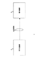
図1は、本実施形態の通信システム1の概念図である。
図1に示すように、通信システム1は、送信側に設けられた符号化装置2と、受信側に設けられた復号装置3とを有する。
符号化装置2が本発明のデータ処理装置および符号化装置に対応している。
通信システム1では、送信側の符号化装置2において、離散コサイン変換やカルーネン・レーベ変換などの直交変換と動き補償によって圧縮したフレーム画像データ(ビットストリーム)を生成し、当該フレーム画像データを変調した後に、衛星放送波、ケーブルTV網、電話回線網、携帯電話回線網などの伝送媒体を介して送信する。
受信側では、復号装置3において受信した画像信号を復調した後に、上記変調時の直交変換の逆変換と動き補償によって伸張したフレーム画像データを生成して利用する。
なお、上記伝送媒体は、光ディスク、磁気ディスクおよび半導体メモリなどの記録媒体であってもよい。
Hereinafter, the
FIG. 1 is a conceptual diagram of a
As shown in FIG. 1, the
The
In the
On the receiving side, after the image signal received by the
The transmission medium may be a recording medium such as an optical disk, a magnetic disk, and a semiconductor memory.
図1に示す復号装置3は従来と同じ構成を有し符号化装置2の符号化に対応した復号を行う。
以下、図1に示す符号化装置2について説明する。
図2は、図1に示す符号化装置2の全体構成図である。
図2に示すように、符号化装置2は、例えば、A/D変換回路22、画面並べ替え回路23、演算回路24、直交変換回路25、量子化回路26、可逆符号化回路27、バッファ28、逆量子化回路29、逆直交変換回路30、フレームメモリ31、レート制御回路32、加算回路33、デブロックフィルタ34、イントラ予測回路41、動き予測・補償回路43および選択回路44を有する。
The
Hereinafter, the
FIG. 2 is an overall configuration diagram of the
As shown in FIG. 2, the
以下、符号化装置2の構成要素について説明する。
A/D変換回路22は、入力されたアナログの輝度信号Y、色差信号Pb,Prから構成される原画像信号をデジタルの画像信号に変換し、これを画面並べ替え回路23に出力する。
画面並べ替え回路23は、A/D変換回路22から入力した原画像信号内のフレーム画像信号を、そのピクチャタイプI,P,BからなるGOP(Group Of Pictures) 構造に応じて、符号化する順番に並べ替えた原画像データS23を演算回路24、動き予測・補償回路43およびイントラ予測回路41に出力する。
Hereinafter, components of the
The A /
The
演算回路24は、原画像データS23と、選択回路44から入力した予測画像データPIとの差分を示す画像データS24を生成し、これを直交変換回路25に出力する。
直交変換回路25は、画像データS24に離散コサイン変換やカルーネン・レーベ変換などの直交変換を施して画像データ(例えばDCT係数)S25を生成し、これを量子化回路26に出力する。
量子化回路26は、レート制御回路32から入力した量子化スケールで、画像データS25を量子化して画像データS26(量子化されたDCT係数)を生成し、これを可逆符号化回路27および逆量子化回路29に出力する。
The
The
The
可逆符号化回路27は、画像データS26を可変長符号化あるいは算術符号化した画像データをバッファ28に格納する。
このとき、可逆符号化回路27は、動き予測・補償回路43から入力した動きベクトルMVあるいはその差分動きベクトル、参照画像データの識別データ、並びにイントラ予測回路41から入力したイントラ予測モードIPMをヘッダデータなどに格納する。
The
At this time, the
バッファ28に格納された画像データは、変調等された後に送信される。
逆量子化回路29は、画像データS26を逆量子化したデータを生成し、これを逆直交変換回路30に出力する。
逆直交変換回路30は、逆量子化回路29から入力したデータに、直交変換回路25における直交変換の逆変換を施して生成した画像データを加算回路33に出力する。
加算回路33は、逆直交変換回路30から入力した(デコードされた)画像データと、選択回路44から入力した予測画像データPIとを加算して再構成画像データを生成し、これをデブロックフィルタ34に出力する。
デブロックフィルタ34は、加算回路33から入力した再構成画像データのブロック歪みを除去した画像データを、参照画像データREFとしてフレームメモリ31に書き込む。
なお、フレームメモリ31には、例えば、動き予測・補償回路43による動き予測・補償処理、並びにイントラ予測回路41におけるイントラ予測処理の対象となっているピクチャの再構成画像データが、処理を終了したマクロブロックMBを単位として順に書き込まれる。
The image data stored in the
The
The inverse
The
The
In the
レート制御回路32は、例えば、バッファ28から読み出した画像データを基に量子化スケールを生成し、これを量子化回路26に出力する。
For example, the
以下、イントラ予測回路41および動き予測・補償回路43について詳細に説明する。
〔イントラ予測回路41〕
イントラ予測回路41は、例えば、イントラ4x4モードおよびイントラ16x16モードなどの複数の予測モードのそれぞれについて処理対象のマクロブロックMBの予測画像データPIiを生成し、これと原画像データS23内の処理対象のマクロブロックMBとを基に、符号化されたデータの符号量の指標となる指標データCOSTiを生成する。
そして、イントラ予測回路41は、指標データCOSTiを最小にするイントラ予測モードを選択する。
イントラ予測回路41は、最終的に選択したイントラ予測モードに対応して生成した予測画像データPIiおよび指標データCOSTiを選択回路44に出力する。
また、イントラ予測回路41は、イントラ予測モードが選択されたことを示す選択信号S44を入力すると、最終的に選択したイントラ予測モードを示す予測モードIPMを可逆符号化回路27に出力する。
なお、PスライスあるいはBスライスに属するマクロブロックMBであっても、イントラ予測回路41によるイントラ予測符号化が行われる場合がある。
Hereinafter, the intra prediction circuit 41 and the motion prediction /
[Intra prediction circuit 41]
For example, the intra prediction circuit 41 generates the predicted image data PIi of the processing target macroblock MB for each of a plurality of prediction modes such as the
Then, the intra prediction circuit 41 selects an intra prediction mode that minimizes the index data COSTi.
The intra prediction circuit 41 outputs the predicted image data PIi and the index data COSTi generated corresponding to the finally selected intra prediction mode to the
In addition, when receiving the selection signal S44 indicating that the intra prediction mode is selected, the intra prediction circuit 41 outputs a prediction mode IPM indicating the finally selected intra prediction mode to the
Note that intra prediction encoding by the intra prediction circuit 41 may be performed even for a macroblock MB belonging to a P slice or a B slice.
イントラ予測回路41は、例えば、指標データCOSTiを下記式(1)に基づいて生成する。 For example, the intra prediction circuit 41 generates the index data COSTi based on the following formula (1).

また、上記式(1)において、「i」は、例えば、処理対象のマクロブロックMBを構成する上記イントラ予測モードに対応したサイズのブロックデータの各々に付された識別番号である。上記式(1)のxは、イントラ16x16モードの場合は「1」であり、イントラ4x4モードの場合には「16」である。
イントラ予測回路41は、処理対象のマクロブロックMBを構成する全てのブロックデータについて、「SATD+header_cost(mode))」を算出し、これらを加算して指標データCOSTiを算出する。
header_cost(mode)は、符号化後の動きベクトル、参照画像データの識別データ、選択されたモード、量子化パラメータ(量子化スケール)などを含むヘッダデータの符号量の指標となる指標データである。header_cost(mode)の値は、予測モードによって異なる。
また、SATDは、処理対象のマクロブロックMB内のブロックデータと、当該ブロックデータの周囲の予め決められたブロックデータ(予測ブロックデータ)との間の差分画像データの符号量の指標となる指標データである。
本実施形態では、単数または複数の予測ブロックデータによって予測画像データPIiが規定される。
In the above equation (1), “i” is, for example, an identification number assigned to each block data having a size corresponding to the intra prediction mode constituting the macroblock MB to be processed. X in the above formula (1) is “1” in the case of the intra 16 × 16 mode, and “16” in the case of the
The intra prediction circuit 41 calculates “SATD + header_cost (mode))” for all block data constituting the macro block MB to be processed, and adds these to calculate the index data COSTi.
header_cost (mode) is index data serving as an index of the code amount of header data including a motion vector after encoding, identification data of reference image data, a selected mode, a quantization parameter (quantization scale), and the like. The value of header_cost (mode) varies depending on the prediction mode.
The SATD is index data that serves as an index of the code amount of the difference image data between the block data in the processing target macroblock MB and predetermined block data (predicted block data) around the block data. It is.
In the present embodiment, the predicted image data PIi is defined by one or a plurality of predicted block data.
SATDは、例えば、下記式(2)に示すように、処理対象のブロックデータOrgと、予測ブロックデータPreとの画素データ間の絶対値誤差和(Sum of Absolute Difference)にアダマール変換(Tran)を施した後のデータである。
下記式(2)のs,tによって、上記ブロックデータ内の画素が指定される。
For example, as shown in the following equation (2), the SATD performs a Hadamard transform (Tran) on an absolute value error sum (Sum of Absolute Difference) between pixel data of the block data Org to be processed and the predicted block data Pre. It is the data after applying.
Pixels in the block data are designated by s and t in the following formula (2).
なお、SATDの代わりに、下記式(3)で示すSADを用いてもよい。
また、SATDの代わりに、MPEG4,AVCで規定されているSSDなどの歪みや残差を表わすその他の指標を用いてもよい。
Instead of SATD, SAD represented by the following formula (3) may be used.
Further, instead of SATD, other indexes representing distortion and residual such as SSD defined in MPEG4 and AVC may be used.
〔動き予測・補償回路43〕
動き予測・補償回路43は、画面並べ替え回路23から入力した原画像データS23の処理対象のマクロブロックMBがインター符号化される場合に、複数の動き予測・補償モードの各々について、フレームメモリ31に記憶された過去に符号化された参照画像データREFを基に、動き予測・補償モードによって規定されたブロックデータを単位として、処理対象のブロックデータの動きベクトルMVおよび予測画像データを生成する。
当該ブロックデータのサイズ、並びに参照画像データREFは、例えば、動き予測・補償モードによって規定される。
また、動き予測・補償回路43は、上記動き予測・補償モードの各々について、原画像データS23内の処理対象のマクロブロックMBと、その予測ブロックデータ(予測画像データPIm)とを基に、符号化されたデータの符号量の指標となる指標データCOSTmを生成する。
そして、動き予測・補償回路43は、指標データCOSTmを最小にする動き予測・補償モードを選択する。
動き予測・補償回路43は、最終的に選択した動き予測・補償モードに対応して生成した予測画像データPImおよび指標データCOSTmを選択回路44に出力する。
また、動き予測・補償回路43は、最終的に選択した動き予測・補償モードに対応して生成した動きベクトル、あるいは当該動きベクトルと予測動きベクトルとの間の差分動きベクトルをを可逆符号化回路27に出力する。
また、動き予測・補償回路43は、最終的に選択された動き予測・補償モードを示す動き予測・補償モードMEMを可逆符号化回路27に出力する。
また、動き予測・補償回路43は、動き予測・補償処理において選択した参照画像デーサ(参照フレーム)の識別データを可逆符号化回路27に出力する。
[Motion prediction / compensation circuit 43]
The motion prediction /
The size of the block data and the reference image data REF are defined by, for example, a motion prediction / compensation mode.
In addition, the motion prediction /
Then, the motion prediction /
The motion prediction /
In addition, the motion prediction /
The motion prediction /
In addition, the motion prediction /
動き予測・補償回路43は、例えば、指標データCOSTmを下記式(4)に基づいて生成する。
For example, the motion prediction /
また、上記式(4)において、「i」は、例えば、処理対象のマクロブロックMBを構成する上記動き予測・補償モードしたサイズのブロックデータの各々に付された識別番号である。
すなわち、動き予測・補償回路43は、処理対象のマクロブロックMBを構成する全てのブロックデータについて、「SATD+head_cost(mode))」を算出し、これらを加算して指標データCOSTmを算出する。
head_cost(mode)は、符号化後の動きベクトル、参照画像データの識別データ、選択されたモードや量子化パラメータ(量子化スケール)などを含むヘッダデータの符号量の指標となる指標データである。header_cost(mode)の値は、動き予測・補償モードによって異なる。
また、SATDは、処理対象のマクロブロックMB内のブロックデータと、動きベクトルMVによって指定される参照画像データ内のブロックデータ(参照ブロックデータ)との間の差分画像データの符合量の指標となる指標データである。
本実施形態では、単数または複数の参照ブロックデータによって予測画像データPImが規定される。
In the above equation (4), “i” is, for example, an identification number assigned to each block data of the size subjected to the motion prediction / compensation mode constituting the macroblock MB to be processed.
That is, the motion prediction /
head_cost (mode) is index data serving as an index of the coding amount of header data including the motion vector after encoding, identification data of reference image data, a selected mode, a quantization parameter (quantization scale), and the like. The value of header_cost (mode) differs depending on the motion prediction / compensation mode.
The SATD is an indicator of the amount of sign of difference image data between the block data in the processing target macroblock MB and the block data (reference block data) in the reference image data specified by the motion vector MV. It is index data.
In the present embodiment, the predicted image data PIm is defined by one or a plurality of reference block data.
SATDは、例えば、下記式(5)に示すように、処理対象のブロックデータOrgと、参照ブロックデータ(予測画像データ)Preとの画素データ間の絶対値誤差和にアダマール変換(Tran)を施した後のデータである。
下記式(5)のs,tによって、上記ブロックデータ内の画素が指定される。
For example, as shown in the following formula (5), SATD performs Hadamard transform (Tran) on the absolute value error sum between pixel data of block data Org to be processed and reference block data (predicted image data) Pre. It is the data after doing.
Pixels in the block data are designated by s and t in the following formula (5).
なお、SATDの代わりに、下記式(6)で示すSADを用いてもよい。
また、SATDの代わりに、MPEG4,AVCで規定されているSSDなどの歪みや残差を表わすその他の指標を用いてもよい。
In place of SATD, SAD represented by the following formula (6) may be used.
Further, instead of SATD, other indexes representing distortion and residual such as SSD defined in MPEG4 and AVC may be used.
本実施形態では、動き予測・補償回路43は、動き予測・補償モードとして、例えば、インター基本モード、Skipモード、Directモードなどの種々のモードを備えている。
In the present embodiment, the motion prediction /
インター基本モードには、インター16x16モード、インター8x16モード、インター16x8モード、インター8x8モード、インター4x8モード、インター4x4モードがあり、それぞれブロックデータのサイズが16x16,8x16,16x8,8x8,4x8,4x4である。
また、インター基本モードの各々のサイズにづいて、前方予測モード、後方予測モード、双方向予測モードが選択可能である。
ここで、前方予測モードは表示順が前の画像データを参照画像データとして用いるモードであり、後方予測モードは表示順が後の画像データを参照画像データとして用いるモードであり、双方向予測モードは表示順が前と後との画像データを参照画像データとして用いるモードである。
本実施形態では、動き予測・補償回路43による動き予測・補償処理では、複数の参照画像データを持つことができる。
Inter basic modes include inter 16x16 mode, inter 8x16 mode, inter 16x8 mode, inter 8x8 mode, inter 4x8 mode, and inter 4x4 mode, and the block data sizes are 16x16, 8x16, 16x8, 8x8, 4x8, and 4x4, respectively. is there.
In addition, a forward prediction mode, a backward prediction mode, and a bidirectional prediction mode can be selected based on each size of the inter basic mode.
Here, the forward prediction mode is a mode in which image data in the previous display order is used as reference image data, the backward prediction mode is a mode in which image data in the later display order is used as reference image data, and the bidirectional prediction mode is This is a mode in which the image data with the display order before and after is used as reference image data.
In the present embodiment, the motion prediction / compensation processing by the motion prediction /
動き予測・補償回路43は、インター基本モードにおいて、動きベクトルあるいはその差分動きベクトルと、量子化された差分画像データである画像データS26を可逆符号化回路27で符号化して画像データS2に含める。
In the inter basic mode, the motion prediction /
次に、Skipモードについて説明する。
Skipモードが最終的に選択されると、符号化装置2の可逆符号化回路27は、画像データS26および動きベクトルMVの何れの情報も符号化しない、すなわち画像データS2には含めない。
なお、可逆符号化回路27は、動き予測・補償回路43が選択した動き予測・補償モードを画像データS2に含める。
復号装置3は、画像データS2に含まれる動き予測・補償モードがSkipモードを示す場合に、処理対象のブロックデータの周囲のブロックデータの動きベクトルを基に予測動きベクトルを生成し、この予測動きベクトルを基に復号画像データを生成する。
Skipモードは、画像データS26および動きベクトルの双方を符号化しないため、符号量を著しく削減できる。
当該Skipモードは、Bピクチャに加えて、Pピクチャについても選択可能である。
Next, the Skip mode will be described.
When the Skip mode is finally selected, the
The
When the motion prediction / compensation mode included in the image data S2 indicates the Skip mode, the
Since the Skip mode does not encode both the image data S26 and the motion vector, the amount of codes can be significantly reduced.
The Skip mode can be selected for a P picture in addition to a B picture.
次に、Directモードについて説明する。
Directモードが最終的に選択されると、符号化装置2の可逆符号化回路27は、動きベクトルMVを符号化しない。
なお、可逆符号化回路27は、動き予測・補償モードと画像データS26とを符号化する。
復号装置3は、画像データS2に含まれる動き予測・補償モードがDirectモードを示す場合に、処理対象のブロックデータの周囲のブロックデータの動きベクトルを基に予測動きベクトルを生成し、この予測動きベクトルと符号化された上記画像データS26とを基に復号画像データを生成する。
Directモードは、動きベクトルを符号化しないため、符号量を削減できる。
当該Skipモードは、Bピクチャについて選択可能である。
Next, the Direct mode will be described.
When the Direct mode is finally selected, the
The
When the motion prediction / compensation mode included in the image data S2 indicates the Direct mode, the
In the Direct mode, since the motion vector is not encoded, the code amount can be reduced.
The Skip mode can be selected for a B picture.
Directモードには、16x16のブロックサイズを用いる16x16Directモードと、8x8のブロックサイズを用いる8x8Directモードとがある。
また、16x16Directモードおよび8x8Directモードの各々には、空間(Spatial) Directモードと、時間(Temporal)Directモードとがある。
動き予測・補償回路43は、空間Directモードの場合に、処理対象のブロックデータの周囲のブロックデータの動きベクトルを用いて、予測動きベクトル(動きベクトル)を生成する。
そして、動き予測・補償回路43は、予測動きベクトルを基に参照ブロックデータを特定して参照画像データPImを生成する。
また、動き予測・補償回路43は、時間Directモードの場合に、処理対象のブロックデータの参照画像データ内の対応する位置のブロックデータの動きベクトルを用いて、予測動きベクトル(動きベクトル)を生成する。
そして、動き予測・補償回路43は、予測動きベクトルを基に参照ブロックデータを特定して参照画像データPImを生成する。
復号装置3は、時間Directモードが指定され、例えば、図3に示すように、フレームデータB内の処理対象のブロックデータがフレームデータRL0,RL1を参照画像データとし、フレームデータRL1内の対応する位置のブロックデータのフレームデータRL0に対しての動きベクトルがMVcである場合に、下記式(7),(8)に従って、動きベクトルMV0,MV1を算出する。
下記式(7),(8)において、TDDは参照画像データRL0と参照画像データRL1との間の表示タイミングの間隔を示し、TDBはフレームデータBと参照画像データRL0との間の表示タイミングの間隔を示す。
The Direct mode includes a 16x16 Direct mode that uses a block size of 16x16 and an 8x8 Direct mode that uses a block size of 8x8.
Each of the 16 × 16 Direct mode and the 8 × 8 Direct mode includes a spatial Direct mode and a temporal Direct mode.
In the spatial direct mode, the motion prediction /
Then, the motion prediction /
Also, the motion prediction /
Then, the motion prediction /
In the
In the following formulas (7) and (8), TD D indicates a display timing interval between the reference image data RL 0 and the reference image data RL 1, and TD B is the frame data B and the reference image data RL 0 . The display timing interval is shown.
図4は、動き予測・補償回路43のハードウェア構成図の一例である。
図4に示すように、動き予測・補償回路43は、例えば、インタフェース51、メモリ52および処理回路53を有し、これらがデータ線50を介して接続されている。
インタフェース51は、画面並べ替え回路23、可逆符号化回路27およびフレームメモリ31とデータ入出力を行う。
メモリ52は、プログラムPRG1、並びに処理回路53の処理に用いられる種々のデータを記憶する。
処理回路53は、メモリ52から読み出したプログラムPRG1に従って、動き予測・補償回路43の処理を統括的に制御する。
FIG. 4 is an example of a hardware configuration diagram of the motion prediction /
As shown in FIG. 4, the motion prediction /
The
The memory 52 stores various data used for the processing of the program PRG1 and the processing circuit 53.
The processing circuit 53 controls the overall processing of the motion prediction /
以下、動き予測・補償回路43の動作例を説明する。
以下に示す動き予測・補償回路43の動作は、処理回路53がプログラムPRG1に従って制御する。
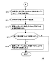
図5および図6は、動き予測・補償回路43の動作例を説明するためのフローチャートである。
動き予測・補償回路43は、以下に示す処理を、原画像データS23内の処理対象のブロックデータについて行う。
ステップST1:
動き予測・補償回路43は、インター16x16,インター8x8、Skip、Direct16x16、Direct8x8のそれぞれについて、上述した手順で処理対象のブロックデータの動きベクトルMV(インター16x16),MV(インター8x8),MV(Skip),MV(Direct16x16),MV(Direct8x8)を生成する。
Hereinafter, an operation example of the motion prediction /
The operation of the motion prediction /
5 and 6 are flowcharts for explaining an operation example of the motion prediction /
The motion prediction /
Step ST1:
The motion prediction /
ステップST2:
動き予測・補償回路43は、ステップST1で生成した動きベクトルMV(skip)と動きベクトルMV(インター16x16)との差分ベクトルの絶対値が、予め決めた基準値MV_RANGEより大きいか否かを判断し、大きいと判断するとステップST3に進み、そうでない場合にはステップST4に進む。
ステップST3:
動き予測・補償回路43は、後述する動き予測・補償モードの選択処理において、Skipモードを非選択にすることを決定する。
ステップST4:
動き予測・補償回路43は、ステップST1で生成した動きベクトルMV(Direct8x8)と動きベクトルMV(インター8x8)との差分ベクトルの絶対値が、予め決めた基準値MV_RANGEより大きいか否かを判断し、大きいと判断するとステップST5に進み、そうでない場合にはステップST6に進む。
ステップST5:
動き予測・補償回路43は、後述する動き予測・補償モードの選択処理において、Direct8x8モードを非選択にすることを決定する。
ステップST6:
動き予測・補償回路43は、ステップST1で生成した動きベクトルMV(Direct16x16)と動きベクトルMV(インター16x16)との差分ベクトルの絶対値が、予め決めた基準値MV_RANGEより大きいか否かを判断し、大きいと判断するとステップST7に進み、そうでない場合にはステップST8に進む。
ステップST7:
動き予測・補償回路43は、後述する動き予測・補償モードの選択処理において、Direct16x16モードを非選択にすることを決定する。
Step ST2:
The motion prediction /
Step ST3:
The motion prediction /
Step ST4:
The motion prediction /
Step ST5:
The motion prediction /
Step ST6:
The motion prediction /
Step ST7:
The motion prediction /
ステップST8:
動き予測・補償回路43は、ステップST3,ST5,ST7によって非選択に指定されなかった動き予測・補償モードについて、前述した手順で指標データCOSTmを算出する。
ステップST9:
動き予測・補償回路43は、ステップST8で算出した指標モードCOSTmを最小にする動き予測・補償モードを選択する。
ステップST10:
動き予測・補償回路43は、上記選択した動き予測・補償モードに対応して生成した予測画像データPImおよび指標データCOSTmを選択回路44に出力する。
ステップST11:
動き予測・補償回路43は、選択回路44から動き予測・補償モードが選択されたことを示す選択信号S44を入力したか否かを所定のタイミングで判断し、入力したと判断するとステップST12に進み、そうでない場合には処理を終了する。
ステップST12:
動き予測・補償回路43は、ステップST9で選択した動き予測・補償モードに対応して生成した動きベクトルMV、あるいはその差分動きベクトル、並びに選択された動き予測・補償モードMEMを可逆符号化回路27に出力する。
Step ST8:
The motion prediction /
Step ST9:
The motion prediction /
Step ST10:
The motion prediction /
Step ST11:
The motion prediction /
Step ST12:
The motion prediction /
〔選択回路44〕
選択回路44は、動き予測・補償回路43から入力した指標データCOSTmと、イントラ予測回路41から入力した指標データCOSTiとのうち小さい方を特定し、当該特定した指標データに対応して入力した予測画像データPImあるいはPIiを演算回路24および加算回路33に出力する。
また、選択回路44は、指標データCOSTmが小さい場合に、動き予測・補償モードを選択したことを示す選択信号S44を動き予測・補償回路43に出力する。
一方、選択回路44は、指標データCOSTiが小さい場合に、イントラ予測モードを選択したことを示す選択信号S44を動き予測・補償回路43に出力する。
なお、本実施形態において、イントラ予測回路41および動き予測・補償回路43がそれぞれ生成した全ての指標データCOSTi,COSTmを選択回路44に出力し、選択回路44において最小の指標データを特定してもよい。
[Selection circuit 44]
The
The
On the other hand, when the index data COSTi is small, the
In the present embodiment, all the index data COSTi and COSTm generated by the intra prediction circuit 41 and the motion prediction /
以下、図2に示す符号化装置2の全体動作を説明する。
入力となる画像信号は、まず、A/D変換回路22においてデジタル信号に変換される。
次に、出力となる画像圧縮情報のGOP構造に応じ、画面並べ替え回路23においてフレーム画像データの並べ替えが行われ、それによって得られた原画像データS23が演算回路24、動き予測・補償回路43およびイントラ予測回路41に出力される。
次に、演算回路24が、画面並べ替え回路23からの原画像データS23と選択回路44からの予測画像データPIとの差分を検出し、その差分を示す画像データS24を直交変換回路25に出力する。
Hereinafter, the overall operation of the
The input image signal is first converted into a digital signal by the A /
Next, the frame image data is rearranged in the
Next, the
次に、直交変換回路25が、画像データS24に離散コサイン変換やカルーネン・レーベ変換等の直交変換を施して画像データ(DCT係数)S25を生成し、これを量子化回路26に出力する。
次に、量子化回路26が、画像データS25を量子化し、画像データ(量子化されたDCT係数)S26を可逆符号化回路27および逆量子化回路29に出力する。
次に、可逆符号化回路27が、画像データS26に可変長符号化あるいは算術符号化等の可逆符号化を施して画像データS28を生成し、これをバッファ28に蓄積する。
また、レート制御回路32が、バッファ28から読み出した画像データS28を基に、量子化回路26における量子化レートを制御する。
Next, the
Next, the
Next, the
Further, the
また、逆量子化回路29が、量子化回路26から入力した画像データS26を逆量子化して逆直交変換回路30に出力する。
そして、逆直交変換回路30が、直交変換回路25の逆変換処理を行って生成した画像データを加算回路33に出力する。
加算回路33において、逆直交変換回路30からの画像データと選択回路44からの予測画像データPIとが加算されて再構成画像データが生成あれ、デブロックフィルタ34に出力される。
そして、デブロックフィルタ34において、再構成画像データのブロック歪みを除去した画像データが生成され、これが参照画像データとして、フレームメモリ31に書き込まれる。
Further, the
Then, the inverse
In the
Then, the
そして、イントラ予測回路41において、上述したイントラ予測処理が行われ、その結果である予測画像データPIiと、指標データCOSTiとが選択回路44に出力される。
また、動き予測・補償回路43において、図5および図6を用いて説明した動き予測・補償処理が行われ、その結果である予測画像データPImと、指標データCOSTmとが選択回路44に出力される。
そして、選択回路44において、動き予測・補償回路43から入力した指標データCOSTmと、イントラ予測回路41から入力した指標データCOSTiとのうち小さい方を特定し、当該特定した指標データに対応して入力した予測画像データPImあるいはPIiを演算回路24および加算回路33に出力する。
The intra prediction circuit 41 performs the above-described intra prediction process, and the prediction image data PIi and the index data COSTi that are the results are output to the
In addition, the motion prediction /
Then, in the
以上説明したように、符号化装置2では、図5および図6を用いて説明したように、動き予測・補償モードのうち、Skip,Direct16x16,Direct8x8モードの動きベクトルMVが、インター基本モードの動きベクトルMVと所定の基準値以上の場合に、これらの動き予測・補償モードを非選択に指定する。
そのため、図6に示すステップST9の処理において、これらの動き予測・補償モードが選択されることを回避できる。
すなわち、符号化装置2では、指標データCOSTmが小さくても、Skip,Direct16x16,Direct8x8モードの動きベクトルMVが本来の動きベクトルと大幅にずれている場合には、インター基本モードを強制的に選択して、動きベクトルあるいはその差分動きベクトルと、量子化された差分画像データである画像データS26を可逆符号化回路27で符号化して画像データS2に含める。
As described above, in the
Therefore, it is possible to avoid selecting these motion prediction / compensation modes in the process of step ST9 shown in FIG.
That is, even if the index data COSTm is small, the
そのため、上述した動きベクトルのずれによって復号画像上で視覚されるジャーキーモションなどを抑制でき、高画質化を図れる。 Therefore, jerky motion visually recognized on the decoded image due to the above-described shift of the motion vector can be suppressed, and high image quality can be achieved.
<第1実施形態の変形例>
上述した実施形態では、図5に示すステップST2,ST4,ST5において、動きベクトル(Skip)とMV(インター16x16)との間で、利用した参照画像データが同じであることを前提としているが、参照画像データが異なる場合にも本発明は適用可能である。
例えば、図7に示すように、フレームデータB内の処理対象のブロックデータが,Direct16x16モードにおいてフレームデータF1を参照画像データとし、インター16x16モードにおいてフレームデータF2を参照画像データとした場合を考える。
この場合には、下記式(9)を基に、動きベクトルMV(インター16x16)を補正した動きベクトルMV1(インター16x16)を図5の判断に用いる。
下記式(9)において、Tdirectは参照画像データF1とフレームデータBとの間の表示タイミングの間隔を示し、TinterはフレームデータBと参照画像データF2との間の表示タイミングの間隔を示す。
<Modification of First Embodiment>
In the above-described embodiment, it is assumed that the used reference image data is the same between the motion vector (Skip) and the MV (Inter 16 × 16) in Steps ST2, ST4, and ST5 shown in FIG. The present invention is also applicable when the reference image data is different.
For example, as shown in FIG. 7, a case is considered where block data to be processed in frame data B uses frame data F1 as reference image data in the Direct 16 × 16 mode and frame data F2 as reference image data in the Inter 16 × 16 mode.
In this case, the motion vector MV1 (inter 16 × 16) obtained by correcting the motion vector MV (inter 16 × 16) based on the following equation (9) is used for the determination of FIG.
In the following formula (9), Tdirect indicates the display timing interval between the reference image data F1 and the frame data B, and Tinter indicates the display timing interval between the frame data B and the reference image data F2.
また、図7に示すように、フレームデータB内の処理対象のブロックデータが,Direct16x16モードにおいてフレームデータF1を参照画像データとし、インター16x16モードにおいてフレームデータF3を参照画像データとした場合を考える。
この場合には、下記式(10)を基に、動きベクトルMV(インター16x16)を補正した動きベクトルMV2(インター16x16)を図5の判断に用いる。
下記式(10)において、Tdirectは参照画像データF1とフレームデータBとの間の表示タイミングの間隔を示し、TinterはフレームデータBと参照画像データF3との間の表示タイミングの間隔を示す。
Further, as shown in FIG. 7, a case is considered in which block data to be processed in frame data B uses frame data F1 as reference image data in the Direct 16 × 16 mode and frame data F3 as reference image data in the Inter 16 × 16 mode.
In this case, the motion vector MV2 (inter 16x16) obtained by correcting the motion vector MV (inter 16x16) based on the following equation (10) is used for the determination in FIG.
In the following formula (10), Tdirect indicates the display timing interval between the reference image data F1 and the frame data B, and Tinter indicates the display timing interval between the frame data B and the reference image data F3.
<第2実施形態>
本実施形態は、第4〜第6の発明に対応した実施形態である。
先ず、本実施形態の構成要素と、本発明の構成要素との関係を説明する。
図9に示すイントラ予測回路41aの処理回路63が図10に示すステップST22で後述する式(12)を基に指標データSATDaを算出することで第4の発明の生成手段が実現される。
また、処理回路63が、図10に示すステップST22で後述する式(11)を基に指標データCOSTaiを算出し、ステップST24を実行することで第4の発明の選択手段が実現される。
また、後述するように、イントラ予測回路41aが、指標データSATD(第1の指標データ)を算出する処理が第5の発明の第1の手順または第6の発明の第1の工程に対応している。
また、イントラ予測回路41aが、Max4x4を特定する処理が、第5の発明の第2の手順または第6の発明の第2の工程に対応している。
また、イントラ予測回路41aが、後述する式(12)を基に指標データSATDa(第2の指標データ)を算出する処理が、第5の発明の第3の手順または第6の発明の第3の工程に対応している。
また、イントラ予測回路41aが、後述する式(11)を基に指標データCOSTai(第3の指標データ)を算出し、図10に示すステップST24を行う処理が、第5の発明の第4の手順または第6の発明の第4の工程に対応している。
また、本実施形態のブロックデータが、本発明のブロックデータに対応している。
Second Embodiment
This embodiment is an embodiment corresponding to the fourth to sixth inventions.
First, the relationship between the component of this embodiment and the component of this invention is demonstrated.
The
Further, the
Further, as will be described later, the process of calculating the index data SATD (first index data) by the
In addition, the process in which the
The
The
Further, the block data of the present embodiment corresponds to the block data of the present invention.
また、同様に、図13に示す動き予測・補償回路43aの処理回路83が図14に示すステップST42で後述する式(15)を基に指標データSATDaを算出することで第4の発明の生成手段が実現される。
また、処理回路83が、図14に示すステップST22で後述する式(14)を基に指標データCOSTamを算出し、ステップST44を実行することで第4の発明の選択手段が実現される。
また、後述するように、動き予測・補償回路43aが、指標データSATD(第1の指標データ)を算出する処理が第5の発明の第1の手順または第6の発明の第1の工程に対応している。
また、動き予測・補償回路43aが、Max4x4を特定する処理が、第5の発明の第2の手順または第6の発明の第2の工程に対応している。
また、動き予測・補償回路43aが、後述する式(15)を基に指標データSATDa(第2の指標データ)を算出する処理が、第5の発明の第3の手順または第6の発明の第3の工程に対応している。
また、動き予測・補償回路43aが、後述する式(14)を基に指標データCOSTam(第3の指標データ)を算出し、図14に示すステップST44を行う処理が、第5の発明の第4の手順または第6の発明の第4の工程に対応している。
Similarly, the
Further, the
Further, as will be described later, the motion prediction /
In addition, the process in which the motion prediction /
In addition, the process in which the motion prediction /
Further, the process of the motion prediction /
また、本実施形態のプログラムPRG2,PRG3の各々が、第5の発明のプログラムに対応している。 Each of the programs PRG2 and PRG3 of the present embodiment corresponds to the program of the fifth invention.
以下、本実施形態に係わる符号化装置について詳細に説明する。
図8は、本発明の実施形態に係わる符号化装置2aの全体構成図である。
図8に示すように、符号化装置2aは、例えば、A/D変換回路22、画面並べ替え回路23、演算回路24、直交変換回路25、量子化回路26、可逆符号化回路27、バッファ28、逆量子化回路29、逆直交変換回路30、フレームメモリ31、レート制御回路32、加算回路33、デブロックフィルタ34、イントラ予測回路41a、動き予測・補償回路43aおよび選択回路44を有する。
図7において、図2と同じ符号を付した構成要素は第1実施形態で説明しものと同じである。
本実施形態の符号化装置2aは、イントラ予測回路41aおよび動き予測・補償回路43aに特徴を有している。
Hereinafter, the encoding apparatus according to the present embodiment will be described in detail.
FIG. 8 is an overall configuration diagram of the
As illustrated in FIG. 8, the
In FIG. 7, components denoted by the same reference numerals as those in FIG. 2 are the same as those described in the first embodiment.
The
〔イントラ予測回路41a〕
イントラ予測回路41aは、例えば、イントラ4x4モードおよびイントラ16x16モードなどの複数の予測モードのそれぞれについて処理対象のマクロブロックMBの予測画像データPIiを生成し、これと原画像データS23内の処理対象のマクロブロックMBとを基に、符号化されたデータの符号量の指標となる指標データCOSTaiを生成する。
そして、イントラ予測回路41aは、指標データCOSTaiを最小にするイントラ予測モードを選択する。
イントラ予測回路41aは、最終的に選択したイントラ予測モードに対応して生成した予測画像データPIiおよび指標データCOSTaiを選択回路44に出力する。
また、イントラ予測回路41aは、イントラ予測モードが選択されたことを示す選択信号S44を入力すると、最終的に選択したイントラ予測モードを示す予測モードIPMを可逆符号化回路27に出力する。
なお、PスライスあるいはBスライスに属するマクロブロックMBであっても、イントラ予測回路41aによるイントラ予測符号化が行われる場合がある。
[
For example, the
Then, the
The
In addition, when receiving the selection signal S44 indicating that the intra prediction mode is selected, the
Note that, even for a macroblock MB belonging to a P slice or a B slice, intra prediction encoding may be performed by the
イントラ予測回路41aは、例えば、指標データCOSTaiを下記式(11)に基づいて生成する。
For example, the
上記式(11)において、「i」は、例えば、処理対象のマクロブロックMBを構成する上記イントラ予測モードに対応したサイズのブロックデータの各々に付された識別番号である。
すなわち、イントラ予測回路41aは、処理対象のマクロブロックMBを構成する全てのブロックデータについて、「SATDa+header_cost(mode))」を算出し、これらを加算して指標データCOSTaiを算出する。
header_cost(mode)は、選択されたイントラ予測モードや量子化パラメータ(量子化スケール)などを含むヘッダデータの符号量の指標となる指標データであり、イントラ予測モードによって異なる値を示す。
また、SATDaは、処理対象のマクロブロックMB内のブロックデータと、当該ブロックデータの周囲の予め決められたブロックデータ(予測ブロックデータ)との間の差分画像データの符号量の指標となる指標データである。
本実施形態では、単数または複数の予測ブロックデータによって予測画像データPIiが規定される。
In the above equation (11), “i” is, for example, an identification number assigned to each block data having a size corresponding to the intra prediction mode constituting the macro block MB to be processed.
That is, the
header_cost (mode) is index data that serves as an index of the code amount of header data including the selected intra prediction mode, quantization parameter (quantization scale), and the like, and indicates a value that varies depending on the intra prediction mode.
SATDa is index data that is an index of the code amount of difference image data between block data in the macroblock MB to be processed and predetermined block data (predicted block data) around the block data. It is.
In the present embodiment, the predicted image data PIi is defined by one or a plurality of predicted block data.
本実施形態は、SATDaの算出方法に特徴を有している。
イントラ予測回路41aは、イントラ16x16モードおよびイントラ4x4モードについての指標データSATDaを、図12(A)および下記式(12)に示すように算出する。
The present embodiment is characterized by a method for calculating SATDa.
The
上記式(12)の「SATD」は、第1実施形態で説明した式(5)と同じである。
但し、本実施形態では、イントラ予測回路41aは、16x16画素データで構成されるブロックデータについて、4x4画素データを単位として上記式(5)の演算を行い、その結果を加算してSATDを算出する。
すなわち、SATDは、例えば、処理対象のブロックデータOrgと、予測画像データ(参照ブロックデータ)Preとの画素データ間の絶対値誤差和にアダマール変換を施した後のデータである。
ここで、イントラ予測回路41aは、ブロックデータ内の各4x4画素データについて行った式(5)の演算結果のうち最大値を特定し、それをMax4x4とする。
そして、イントラ予測回路41aは、SATDに「Max4x4*16」を加算して2で除算することで、指標データSATDaを算出する。
イントラ予測回路41aは、上記式(12)を用いることで、SATDのみを用いる場合に比べて、Max4x4(差分の最大値)の影響が強く反映された指標データSATDaを算出できる。
“SATD” in Expression (12) is the same as Expression (5) described in the first embodiment.
However, in the present embodiment, the
That is, SATD is, for example, data obtained by performing Hadamard transform on the absolute value error sum between pixel data of block data Org to be processed and predicted image data (reference block data) Pre.
Here, the
Then, the
The
なお、SATDの代わりに、第1実施形態の式(3)で示すSADを用いてもよい。
また、SATDの代わりに、MPEG4,AVCで規定されているSSDなどの歪みや残差を表わすその他の指標を用いてもよい。
Note that, instead of SATD, SAD represented by Formula (3) of the first embodiment may be used.
Further, instead of SATD, other indexes representing distortion and residual such as SSD defined in MPEG4 and AVC may be used.
図9は、図8に示すイントラ予測回路41aのハードウェア構成図の一例である。
図9に示すように、イントラ予測回路41aは、例えば、インタフェース61、メモリ62および処理回路63を有し、これらがデータ線60を介して接続されている。
インタフェース61は、画面並べ替え回路23、可逆符号化回路27およびフレームメモリ31とデータ入出力を行う。
メモリ62は、プログラムPRG2、並びに処理回路63の処理に用いられる種々のデータを記憶する。
処理回路63は、メモリ62から読み出したプログラムPRG2に従って、イントラ予測回路41a処理を統括的に制御する。
FIG. 9 is an example of a hardware configuration diagram of the
As illustrated in FIG. 9, the
The
The memory 62 stores the program PRG2 and various data used for the processing of the
The
以下、イントラ予測回路41aの動作例を説明する。
以下に示すイントラ予測回路41aの動作は、処理回路63がプログラムPRG2に従って制御する。
図10は、イントラ予測回路41aの動作例を説明するためのフローチャートである。
イントラ予測回路41aは、以下に示す処理を、原画像データS23内の処理対象のブロックデータについて行う。
ステップST21:
イントラ予測回路41aは、イントラ16x16モードおよびイントラ4x4モードを含む複数のイントラ予測モードのうち未処理のイントラ予測モードを特定する。
ステップST22:
イントラ予測回路41aは、ステップST21で特定したイントラ予測モードについて、上述した式(12)を用いて説明した手法で指標データCOSTaiを算出する。
ステップST23:
イントラ予測回路41aは、全てのイントラ予測モードについて、ステップST22の処理を終了したか否かを判断し、終了したと判断するとステップST24に進み、そうでない場合にはステップST21に戻る。
Hereinafter, an operation example of the
The operation of the
FIG. 10 is a flowchart for explaining an operation example of the
The
Step ST21:
The
Step ST22:
The
Step ST23:
The
ステップST24:
イントラ予測回路41aは、全てのイントラ予測モードについてステップST22で算出した指標データCOSTaiのうち最小のイントラ予測モードを選択する。
ステップST25:
イントラ予測回路41aは、ステップST24で選択したイントラ予測モードに対応して生成した予測画像データPIiおよび指標データCOSTaiを選択回路44に出力する。
ステップST26:
イントラ予測回路41aは、選択回路44からイントラ予測モードが選択されたことを示す選択信号S44を入力したか否かを所定のタイミングで判断し、入力したと判断するとステップST27に進み、そうでない場合には処理を終了する。
ステップST27:
イントラ予測回路41aは、ステップST24で選択したイントラ予測モードIPMを可逆符号化回路27に出力する。
Step ST24:
The
Step ST25:
The
Step ST26:
The
Step ST27:
The
なお、イントラ予測回路41aは、図9に示す構成の代わりに、例えば、図11に示すように、SATD算出回路71、最大値特定回路72、COST算出回路73およびモード判定回路74を備えてもよい。
ここで、SATD算出回路71は、上記式(5)の演算を行い、その結果を加算してSATDを算出する。
また、最大値特定回路72は、ブロックデータ内の各4x4画素データについて行った式(5)の演算結果のうち最大値を特定し、それをMax4x4とする。
COST算出回路73は、SATDに「Max4x4*16」を加算して2で除算することで、指標データSATDaを算出する。
また、モード判定回路74は、図10に示すステップST24の処理を行う。
Note that the
Here, the
Further, the maximum
The
Further, the
〔動き予測・補償回路43a〕
動き予測・補償回路43aは、画面並べ替え回路23から入力した原画像データS23の処理対象のマクロブロックMBがインター符号化される場合に、複数の動き予測・補償モードの各々について、フレームメモリ31に記憶された過去に符号化された参照画像データREFを基に、動き予測・補償モードによって規定されたブロックデータを単位として、処理対象のブロックデータの動きベクトルMVおよび予測画像データを生成する。
当該ブロックデータのサイズ、並びに参照画像データREFは、例えば、動き予測・補償モードによって規定される。
また、動き予測・補償回路43aは、上記動き予測・補償モードの各々について、原画像データS23内の処理対象のマクロブロックMBと、その予測ブロックデータ(予測画像データPIm)とを基に、符号化されたデータの符号量の指標となる指標データCOSTamを生成する。
そして、動き予測・補償回路43aは、指標データCOSTamを最小にする動き予測・補償モードを選択する。
動き予測・補償回路43aは、最終的に選択した動き予測・補償モードに対応して生成した予測画像データPImおよび指標データCOSTmaを選択回路44に出力する。
また、動き予測・補償回路43aは、最終的に選択した動き予測・補償モードに対応して生成した動きベクトル、あるいは当該動きベクトルと予測動きベクトルとの間の差分動きベクトルを可逆符号化回路27に出力する。
また、動き予測・補償回路43aは、最終的に選択された動き予測・補償モードMEMを可逆符号化回路27に出力する。
また、動き予測・補償回路43aは、動き予測・補償処理において選択した参照画像デーサ(参照フレーム)の識別データを可逆符号化回路27に出力する。
[Motion prediction /
The motion prediction /
The size of the block data and the reference image data REF are defined by, for example, a motion prediction / compensation mode.
In addition, the motion prediction /
Then, the motion prediction /
The motion prediction /
In addition, the motion prediction /
In addition, the motion prediction /
In addition, the motion prediction /
動き予測・補償回路43aは、例えば、指標データCOSTamを下記式(13)に基づいて生成する。
For example, the motion prediction /
上記式(13)において、「i」は、例えば、処理対象のマクロブロックMBを構成する上記動き予測・補償モードに対応したサイズのブロックデータの各々に付された識別番号である。
すなわち、動き予測・補償回路43aは、処理対象のマクロブロックMBを構成する全てのブロックデータについて、「SATDa+header_cost(mode))」を算出し、これらを加算して指標データCOSTamを算出する。
header_cost(mode)は、動きベクトルあるいはその差分動きベクトル、参照画像データの識別データ、選択された動き予測・補償モード、量子化パラメータ(量子化スケール)などを含むヘッダデータの符号量の指標となる指標データであり、動き予測・補償モードによって異なる値を示す。
また、SATDaは、処理対象のマクロブロックMB内のブロックデータと、当該ブロックデータの周囲の予め決められたブロックデータ(予測ブロックデータ)との間の差分画像データの符号量の指標となる指標データである。
本実施形態では、単数または複数の予測ブロックデータによって予測画像データPImが規定される。
In the above equation (13), “i” is, for example, an identification number assigned to each block data having a size corresponding to the motion prediction / compensation mode constituting the macroblock MB to be processed.
That is, the motion prediction /
header_cost (mode) is an index of the code amount of header data including a motion vector or a differential motion vector thereof, identification data of reference image data, a selected motion prediction / compensation mode, a quantization parameter (quantization scale), and the like. This is index data and shows different values depending on the motion prediction / compensation mode.
SATDa is index data that is an index of the code amount of difference image data between block data in the macroblock MB to be processed and predetermined block data (predicted block data) around the block data. It is.
In the present embodiment, the predicted image data PIm is defined by one or a plurality of predicted block data.
本実施形態は、SATDaの算出方法に特徴を有している。
動き予測・補償回路43aは、第1実施形態で説明したインター16x16モード、イントラ16x16モード、イントラ4x4モード、Skipモード、Direct16x16モードについての指標データSATDaを、図12(A)および下記式(14)に示すように算出する。
The present embodiment is characterized by a method for calculating SATDa.
The motion prediction /
上記式(14)の「SATD」は、第1実施形態で説明した式(5)と同じである。
但し、動き予測・補償回路43aは、16x16画素データで構成されるブロックデータについて、4x4画素データを単位として上記式(5)の演算を行い、その結果を加算してSATDを算出する。
すなわち、SATDは、例えば、処理対象のブロックデータOrgと、予測画像データ(参照ブロックデータ)Preとの画素データ間の絶対値誤差和にアダマール変換を施した後のデータである。
ここで、動き予測・補償回路43aは、ブロックデータ内の各4x4画素データについて行った式(5)の演算結果のうち最大値を特定し、それをMax4x4とする。
そして、動き予測・補償回路43aは、SATDに「Max4x4*16」を加算して2で除算することで、指標データSATDaを算出する。
動き予測・補償回路43aは、上記式(14)を用いることで、SATDのみを用いる場合に比べて、Max4x4(差分の最大値)の影響が強く反映された指標データSATDaを算出できる。
“SATD” in Expression (14) is the same as Expression (5) described in the first embodiment.
However, the motion prediction /
That is, SATD is, for example, data obtained by performing Hadamard transform on the absolute value error sum between pixel data of block data Org to be processed and predicted image data (reference block data) Pre.
Here, the motion prediction /
Then, the motion prediction /
The motion prediction /
また、動き予測・補償回路43aは、インター8x16モードおびインター16x8モードについての指標データSATDaを、図12(B)および下記式(15)に示すように算出する。
Further, the motion prediction /
上記式(15)の「SATD」は、第1実施形態で説明した式(5)と同じである。
但し、動き予測・補償回路43aは、8x16あるいは16x8画素データで構成されるブロックデータについて、4x4画素データを単位として上記式(5)の演算を行い、その結果を加算してSATDを算出する。
すなわち、SATDは、例えば、処理対象のブロックデータOrgと、予測画像データ(参照ブロックデータ)Preとの画素データ間の絶対値誤差和にアダマール変換を施した後のデータである。
ここで、動き予測・補償回路43aは、ブロックデータ内の各4x4画素データについて行った式(5)の演算結果のうち最大値を特定し、それをMax4x4とする。
そして、動き予測・補償回路43aは、SATDに「Max4x4*8」を加算して2で除算することで、指標データSATDaを算出する。
動き予測・補償回路43aは、上記式(15)を用いることで、SATDのみを用いる場合に比べて、Max4x4(差分の最大値)の影響が強く反映された指標データSATDaを算出できる。
“SATD” in equation (15) is the same as equation (5) described in the first embodiment.
However, the motion prediction /
That is, SATD is, for example, data obtained by performing Hadamard transform on the absolute value error sum between pixel data of block data Org to be processed and predicted image data (reference block data) Pre.
Here, the motion prediction /
The motion prediction /
The motion prediction /
また、動き予測・補償回路43aは、インター8x8モードおよび第1実施形態で説明したDirect8x8モードについての指標データSATDaを、図12(C)および下記式(16)に示すように算出する。
Further, the motion prediction /
上記式(16)の「SATD」は、第1実施形態で説明した式(5)と同じである。
但し、動き予測・補償回路43aは、8x8画素データで構成されるブロックデータについて、4x4画素データを単位として上記式(5)の演算を行い、その結果を加算してSATDを算出する。
すなわち、SATDは、例えば、処理対象のブロックデータOrgと、予測画像データ(参照ブロックデータ)Preとの画素データ間の絶対値誤差和にアダマール変換を施した後のデータである。
ここで、動き予測・補償回路43aは、ブロックデータ内の各4x4画素データについて行った式(5)の演算結果のうち最大値を特定し、それをMax4x4とする。
そして、動き予測・補償回路43aは、SATDに「Max4x4*4」を加算して2で除算することで、指標データSATDaを算出する。
動き予測・補償回路43aは、上記式(16)を用いることで、SATDのみを用いる場合に比べて、Max4x4(差分の最大値)の影響が強く反映された指標データSATDaを算出できる。
“SATD” in Expression (16) is the same as Expression (5) described in the first embodiment.
However, the motion prediction /
That is, SATD is, for example, data obtained by performing Hadamard transform on the absolute value error sum between pixel data of block data Org to be processed and predicted image data (reference block data) Pre.
Here, the motion prediction /
Then, the motion prediction /
The motion prediction /
また、動き予測・補償回路43aは、インター4x8モードおよびインター8x4モードについての指標データSATDaを、図12(D)および下記式(17)に示すように算出する。
Further, the motion prediction /
上記式(17)の「SATD」は、第1実施形態で説明した式(5)と同じである。
但し、動き予測・補償回路43aは、8x4あるいは4x8画素データで構成されるブロックデータについて、4x4画素データを単位として上記式(5)の演算を行い、その結果を加算してSATDを算出する。
すなわち、SATDは、例えば、処理対象のブロックデータOrgと、予測画像データ(参照ブロックデータ)Preとの画素データ間の絶対値誤差和にアダマール変換を施した後のデータである。
ここで、動き予測・補償回路43aは、ブロックデータ内の各4x4画素データについて行った式(5)の演算結果のうち最大値を特定し、それをMax4x4とする。
そして、動き予測・補償回路43aは、SATDに「Max4x4*2」を加算して2で除算することで、指標データSATDaを算出する。
動き予測・補償回路43aは、上記式(17)を用いることで、SATDのみを用いる場合に比べて、Max4x4(差分の最大値)の影響が強く反映された指標データSATDaを算出できる。
“SATD” in Expression (17) is the same as Expression (5) described in the first embodiment.
However, the motion prediction /
That is, SATD is, for example, data obtained by performing Hadamard transform on the absolute value error sum between pixel data of block data Org to be processed and predicted image data (reference block data) Pre.
Here, the motion prediction /
The motion prediction /
The motion prediction /
また、動き予測・補償回路43aは、インター4x4モードについての指標データSATDaを、図12(E)および下記式(18)に示すように算出する。
Further, the motion prediction /
上記式(18)の「SATD」は、第1実施形態で説明した式(5)と同じである。
但し、動き予測・補償回路43aは、4x4で構成されるブロックデータについて、4x4画素データを単位として上記式(5)の演算を行い、その結果を加算してSATDを算出する。
すなわち、SATDは、例えば、処理対象のブロックデータOrgと、予測画像データ(参照ブロックデータ)Preとの画素データ間の絶対値誤差和にアダマール変換を施した後のデータである。
ここで、動き予測・補償回路43aは、ブロックデータ内の各4x4画素データについて行った式(5)の演算結果のうち最大値を特定し、それをMax4x4とする。
そして、動き予測・補償回路43aは、SATDに「Max4x4」を加算して2で除算することで、指標データSATDaを算出する。
動き予測・補償回路43aは、上記式(18)を用いることで、SATDのみを用いる場合に比べて、Max4x4(差分の最大値)の影響が強く反映された指標データSATDaを算出できる。
“SATD” in the equation (18) is the same as the equation (5) described in the first embodiment.
However, the motion prediction /
That is, SATD is, for example, data obtained by performing Hadamard transform on the absolute value error sum between pixel data of block data Org to be processed and predicted image data (reference block data) Pre.
Here, the motion prediction /
Then, the motion prediction /
The motion prediction /
なお、SATDの代わりに、第1実施形態の式(3)で示すSADを用いてもよい。 Note that, instead of SATD, SAD represented by Formula (3) of the first embodiment may be used.
図13は、図8に示す動き予測・補償回路43aのハードウェア構成図の一例である。
図13に示すように、動き予測・補償回路43aは、例えば、インタフェース81、メモリ82および処理回路83を有し、これらがデータ線80を介して接続されている。
インタフェース81は、画面並べ替え回路23、可逆符号化回路27およびフレームメモリ31とデータ入出力を行う。
メモリ82は、プログラムPRG3、並びに処理回路83の処理に用いられる種々のデータを記憶する。
処理回路83は、メモリ82から読み出したプログラムPRG3に従って、動き予測・補償回路43a処理を統括的に制御する。
FIG. 13 is an example of a hardware configuration diagram of the motion prediction /
As shown in FIG. 13, the motion prediction /
The
The memory 82 stores the program PRG3 and various data used for the processing of the
The
以下、動き予測・補償回路43aの動作例を説明する。
以下に示す動き予測・補償回路43aの動作は、処理回路83がプログラムPRG3に従って制御する。
図14は、動き予測・補償回路43aの動作例を説明するためのフローチャートである。
動き予測・補償回路43aは、以下に示す処理を、原画像データS23内の処理対象のブロックデータについて行う。
ステップST41:
動き予測・補償回路43aは、インター16x16モード、Skipモード、Direct16x16モード、インター8x16モード、インター16x8モード、インター8x8モード、Direct8x8モード、インター4x8モード、インター8x4モード、インター4x4モードを含む複数の動き予測・補償モードのうち未処理の動き予測・補償モードを特定する。
ステップST42:
動き予測・補償回路43aは、ステップST41で特定した動き予測・補償モードについて、上述した手法で指標データCOSTamを算出する。
ステップST43:
動き予測・補償回路43aは、全ての動き予測・補償モードについて、ステップST42の処理を終了したか否かを判断し、終了したと判断するとステップST44に進み、そうでない場合にはステップST41に戻る。
Hereinafter, an operation example of the motion prediction /
The operation of the motion prediction /
FIG. 14 is a flowchart for explaining an operation example of the motion prediction /
The motion prediction /
Step ST41:
The motion prediction /
Step ST42:
The motion prediction /
Step ST43:
The motion prediction /
ステップST44:
動き予測・補償回路43aは、全ての動き予測・補償モードについてステップST42で算出した指標データCOSTamのうち最小の動き予測・補償モードを選択する。
ステップST45:
動き予測・補償回路43aは、ステップST44で選択した動き予測・補償モードに対応して生成した予測画像データPImiおよび指標データCOSTamを選択回路44に出力する。
ステップST46:
動き予測・補償回路43aは、選択回路44から動き予測・補償モードが選択されたことを示す選択信号S44を入力したか否かを所定のタイミングで判断し、入力したと判断するとステップST47に進み、そうでない場合には処理を終了する。
ステップST47:
動き予測・補償回路43aは、ステップST44で選択した動き予測・補償モードMPM、動きベクトルMV、並びに参照画像データの識別データを可逆符号化回路27に出力する。
Step ST44:
The motion prediction /
Step ST45:
The motion prediction /
Step ST46:
The motion prediction /
Step ST47:
The motion prediction /
なお、動き予測・補償回路43aは、図13に示す構成の代わりに、例えば、図15に示すように、SATD算出回路91、最大値特定回路92、COST算出回路93およびモード判定回路94を備えてもよい。
ここで、SATD算出回路91は、上記式(5)の演算を行い、その結果を加算してSATDを算出する。
また、最大値特定回路92は、ブロックデータ内の各4x4画素データについて行った式(5)の演算結果のうち最大値を特定し、それをMax4x4とする。
COST算出回路93は、SATDを用いて前述したように、指標データSATDaを算出する。
また、モード判定回路74は、図14に示すステップST44の処理を行う。
The motion prediction /
Here, the
Further, the maximum
The
Further, the
符号化装置2aの全体動作例は、イントラ予測回路41aおよび動き予測・補償回路43において上述した動作が行われる点を除いて、第1実施形態の符号化装置2と同じである。
なお、本実施形態においても、イントラ予測回路41aおよび動き予測・補償回路43aがそれぞれ生成した全ての指標データCOSTai,COSTamを選択回路44に出力し、選択回路44において最小の指標データを特定してもよい。
The overall operation example of the
Also in this embodiment, all index data COSTai and COSTam generated by the
以上説明したように、符号化装置2aでは、イントラ予測回路41aおよび動き予測・補償回路43aのモード選択において、SATDのみを用いる場合に比べて、Max4x4(差分の最大値)の影響が強く反映された指標データSATDaを用いる。
そのため、符号化装置2aによれば、処理対象のマクロブロック内の一部のブロックの符号量が大きく、それ以外の大半のブロックの符号量が小さい場合でも、上記一部のブロックの符号化に画質の観点から適切なモードが選択することができ、高画質な画像を提供できる。
As described above, in the
Therefore, according to the
<第2実施形態の変形例>
上述した第2実施形態では、図12および式(12),式(14)〜(18)を基に指標データSATDaを算出する場合を例示したが、本実施形態では、イントラ予測回路41aおよび動き予測・補償回路43aが、図16および以下に示す式(19)〜(23)に示すように、指標データSATDaを算出する。
下記式(19)〜(23)において、a,b,c,d,e,f,g,h,i,jは、所定の係数である。
ここで、係数a,c,e,g,iが第4の発明の第1の係数に対応し、係数b,d,f,h,jが第4の発明の第2の係数に対応している。
<Modification of Second Embodiment>
In the second embodiment described above, the case where the index data SATDa is calculated based on FIG. 12 and the equations (12) and (14) to (18) is exemplified. However, in this embodiment, the
In the following formulas (19) to (23), a, b, c, d, e, f, g, h, i, j are predetermined coefficients.
Here, the coefficients a, c, e, g, i correspond to the first coefficient of the fourth invention, and the coefficients b, d, f, h, j correspond to the second coefficient of the fourth invention. ing.
例えば、イントラ予測回路41aは、インター16x16モードにおいて、図16(A)および下記式(19)を基に、指標データSATDaを算出する。
For example, the
また、イントラ予測回路41aおよび動き予測・補償回路43aは、イントラ16x16モード、イントラ4x4モード、Skipモード、Direct16x16モードにおいて、図16(B)および下記式(20)を基に、指標データSATDaを算出する。
In addition, the
また、動き予測・補償回路43aは、インター8x16モード、インター16x8モードにおいて、図16(C)および下記式(21)を基に、指標データSATDaを算出する。
In addition, the motion prediction /
また、動き予測・補償回路43aは、インター8x8モード、Direct8x8モードにおいて、図16(D)および下記式(22)を基に、指標データSATDaを算出する。
In addition, the motion prediction /
また、動き予測・補償回路43aは、インター4x8モード、インター8x4モードにおいて、図16(E)および下記式(23)を基に、指標データSATDaを算出する。
Further, the motion prediction /
また、動き予測・補償回路43aは、インター4x4モードにおいて、図16(F)および下記式(24)を基に、指標データSATDaを算出する。
The motion prediction /
本実施形態では、例えば、係数a,b,c,d,e,f,g,h,i,jを、外部から設定可能とし、SATDと、Max4x4との重み付けを自由に設定できる。
例えば、本実施形態では、a=15,b=1,c=7,d=1,e=1,f=1,g=3,h=1,i=1,j=1と設定してもよい。
In the present embodiment, for example, the coefficients a, b, c, d, e, f, g, h, i, and j can be set from the outside, and the weights of SATD and Max4 × 4 can be freely set.
For example, in this embodiment, a = 15, b = 1, c = 7, d = 1, e = 1, f = 1, g = 3, h = 1, i = 1, and j = 1. Also good.
本発明は上述した実施形態には限定されない。
本発明は、上述したイントラ予測モードおよび動き予測・補償モード以外のモードを用いてもよい。
The present invention is not limited to the embodiment described above.
The present invention may use modes other than the intra prediction mode and the motion prediction / compensation mode described above.
画像データを符号化するシステムに適用可能である。 The present invention can be applied to a system that encodes image data.
1…通信システム、2…符号化装置、3…復号装置、22…A/D変換回路、23…画面並べ替え回路、24…演算回路、25…直交変換回路、26…量子化回路、27…可逆符号化回路、28…バッファ、29…逆量子化回路、30…逆直交変換回路、31…フレームメモリ、32…レート制御回路、33…加算回路、34…デブロックフィルタ、41…イントラ予測回路、43…動き予測・補償回路、44…選択回路
DESCRIPTION OF
Claims (15)
前記処理対象のブロックデータの前記動きベクトルを他のブロックデータの動きベクトルから予測し、当該予測した動きベクトルを符号化しない第1のモードと、前記処理対象のブロックデータと参照画像データ内のブロックデータとの差分を基に当該処理対象のブロックデータの動きベクトルを生成し、当該動きベクトルと、前記処理対象のブロックデータと前記参照画像データ内の前記生成した動きベクトルに対応した参照ブロックデータとの差分画像データとを符号化する第2のモードとのそれぞれについて生成した前記動きベクトル間の差分が所定の基準を超えるか否かを判断する判断手段と、
前記判断手段が前記所定の基準を超えると判断した場合に前記第2のモードを選択し、前記判断手段が前記所定の基準を超えないと判断した場合に、前記第1のモードおよび前記第2のモードのうち符号化による符号量が最小となるモードを選択する選択手段と
を有する画像処理装置。 A motion vector of block data of the block to be processed among a plurality of blocks defined in a two-dimensional image region is generated, the motion vector, predicted block data generated based on the motion vector, and the processing target An image processing apparatus used to encode a difference from the block data of
A first mode in which the motion vector of the block data to be processed is predicted from motion vectors of other block data and the predicted motion vector is not encoded; and the blocks in the block data to be processed and reference image data Generating a motion vector of the block data to be processed based on the difference from the data, the motion vector, the block data to be processed, and the reference block data corresponding to the generated motion vector in the reference image data; Determining means for determining whether or not a difference between the motion vectors generated for each of the second mode for encoding the difference image data of the second image and the second image exceeds a predetermined reference;
The second mode is selected when the determination means determines that the predetermined reference is exceeded, and the first mode and the second mode are selected when the determination means determines that the predetermined reference is not exceeded. An image processing apparatus comprising: a selecting unit that selects a mode in which a code amount by encoding is the smallest among the modes.
をさらに有する
請求項1に記載の画像処理装置。 The image processing apparatus according to claim 1, further comprising a providing unit configured to provide the decoding destination with identification data of the mode selected by the selection unit and data defined by the selected mode.
請求項1に記載の画像処理装置。 The image according to claim 1, wherein the selection unit uses the first mode in which difference image data between the block data to be processed and reference block data indicated by the predicted motion vector in the reference image data is further encoded. Processing equipment.
請求項3に記載の画像処理装置。 The image processing apparatus according to claim 3, wherein the selection unit uses the first mode in which the prediction is performed from a motion vector of the other block data in the frame data or field data to which the block data to be processed belongs.
請求項3に記載の画像処理装置。 The selection unit uses the first mode in which the prediction is performed from a motion vector of the other block data in frame data or field data different from frame data or field data to which the block data to be processed belongs. An image processing apparatus according to 1.
請求項1に記載の画像処理装置。 The selection unit uses the first mode in which difference image data between the block data to be processed and reference block data indicated by the predicted motion vector in the reference image data is not provided to the decoding destination. The image processing apparatus described.
請求項1に記載の画像処理装置。 When the frame data or the field data used for generating the motion vector is different between the first mode and the second mode, the determination unit determines the motion vector generated for one mode. The image processing apparatus according to claim 1, wherein conversion is performed so as to correspond to the reference image data used for the other mode, and the difference is generated using the converted motion vector.
前記処理対象のブロックデータの前記動きベクトルを他のブロックデータの動きベクトルから予測し、当該予測した動きベクトルを符号化しない第1のモードと、前記処理対象のブロックデータと参照画像データ内のブロックデータとの差分を基に当該処理対象のブロックデータの動きベクトルを生成し、当該動きベクトルと、前記処理対象のブロックデータと前記参照画像データ内の前記生成した動きベクトルに対応した参照ブロックデータとの差分画像データとを符号化する第2のモードとのそれぞれについて動きベクトルを生成する第1の手順と、
前記第1の手順で生成した前記第1のモードの動きベクトルと前記第2のモードの動きベクトルとの間の差分が所定の基準を超えるか否かを判断する第2の手順と、
前記第2の手順で前記所定の基準を超えると判断した場合に前記第2のモードを選択し、前記所定の基準を超えないと判断した場合に、前記第1のモードおよび前記第2のモードのうち符号化による符号量が最小となるモードを選択する第3の手順と
を前記コンピュータに実行させるプログラム。 A motion vector of block data of the block to be processed among a plurality of blocks defined in a two-dimensional image region is generated, the motion vector, predicted block data generated based on the motion vector, and the processing target A program for causing a computer to execute a process for encoding a difference from the block data of
A first mode in which the motion vector of the block data to be processed is predicted from motion vectors of other block data and the predicted motion vector is not encoded; and the blocks in the block data to be processed and reference image data Generating a motion vector of the block data to be processed based on the difference from the data, the motion vector, the block data to be processed, and the reference block data corresponding to the generated motion vector in the reference image data; A first procedure for generating a motion vector for each of the second mode for encoding the difference image data of
A second procedure for determining whether or not a difference between the motion vector of the first mode and the motion vector of the second mode generated in the first procedure exceeds a predetermined reference;
The second mode is selected when it is determined in the second procedure that the predetermined standard is exceeded, and the first mode and the second mode are selected when it is determined that the predetermined standard is not exceeded. A program for causing the computer to execute a third procedure for selecting a mode in which the amount of code by encoding is the smallest.
前記処理対象のブロックデータの前記動きベクトルを他のブロックデータの動きベクトルから予測し、当該予測した動きベクトルを符号化しない第1のモードと、前記処理対象のブロックデータと参照画像データ内のブロックデータとの差分を基に当該処理対象のブロックデータの動きベクトルを生成し、当該動きベクトルと、前記処理対象のブロックデータと前記参照画像データ内の前記生成した動きベクトルに対応した参照ブロックデータとの差分画像データとを符号化する第2のモードとのそれぞれについて動きベクトルを生成する第1の工程と、
前記第1の工程で生成した前記第1のモードの動きベクトルと前記第2のモードの動きベクトルとの間の差分が所定の基準を超えるか否かを判断する第2の工程と、
前記第2の工程で前記所定の基準を超えると判断した場合に前記第2のモードを選択し、前記所定の基準を超えないと判断した場合に、前記第1のモードおよび前記第2のモードのうち符号化による符号量が最小となるモードを選択する第3の工程と
を有する画像処理方法。 A motion vector of block data of the block to be processed among a plurality of blocks defined in a two-dimensional image region is generated, the motion vector, predicted block data generated based on the motion vector, and the processing target An image processing method in which a computer executes a process for encoding a difference from the block data of
A first mode in which the motion vector of the block data to be processed is predicted from motion vectors of other block data and the predicted motion vector is not encoded; and the blocks in the block data to be processed and reference image data Generating a motion vector of the block data to be processed based on the difference from the data, the motion vector, the block data to be processed, and the reference block data corresponding to the generated motion vector in the reference image data; A first step of generating a motion vector for each of the second mode for encoding the difference image data of
A second step of determining whether a difference between the motion vector of the first mode generated in the first step and the motion vector of the second mode exceeds a predetermined reference;
When it is determined in the second step that the predetermined standard is exceeded, the second mode is selected, and when it is determined that the predetermined standard is not exceeded, the first mode and the second mode are selected. An image processing method comprising: a third step of selecting a mode in which a code amount by encoding is minimized.
処理対象の前記ブロックデータを構成する単数または複数の単位ブロックデータを単位として、当該単位ブロックデータと当該単位ブロックデータに対応した予測ブロックデータ内の単位ブロックデータとの差分に応じた第1の指標データを生成し、前記第1の指標データのうち最大値を示す第1の指標データを特定し、前記第1の指標データを基に、前記処理対象のブロックデータを構成する前記単位ブロックデータについて生成した前記第1の指標データの総和に比べて、前記特定した前記第1の指標データが値として強く反映された第2の指標データを生成する生成手段と、
処理対象の前記マクロブロックについて規定された前記ブロックデータのサイズ、動きベクトルの符号化の有無、並びに前記差分の符号化の有無のうち少なくとも一つが相互に異なる複数のモードのうち、前記処理対象のマクロブロックを構成する単数または複数の前記ブロックデータについて前記生成手段が生成した前記第2の指標データの総和に応じた第3の指標データを最小にするモードを選択する選択手段と
を有する画像処理装置。 The block data is encoded based on the block data of the block to be processed among one or a plurality of blocks constituting the macroblock defined in the two-dimensional image region and the predicted block data of the block data. An image processing apparatus used for
The first index corresponding to the difference between the unit block data and the unit block data in the prediction block data corresponding to the unit block data, with one or more unit block data constituting the block data to be processed as a unit Generating unit data, identifying first index data indicating the maximum value among the first index data, and regarding the unit block data constituting the block data to be processed based on the first index data Generating means for generating second index data in which the identified first index data is strongly reflected as a value compared to the total of the generated first index data;
Among the plurality of modes in which at least one of the size of the block data specified for the macroblock to be processed, the presence / absence of encoding of a motion vector, and the presence / absence of encoding of the difference is different from each other, the processing target And a selection unit that selects a mode that minimizes the third index data corresponding to the sum of the second index data generated by the generation unit for one or a plurality of the block data constituting the macroblock. apparatus.
請求項10に記載の画像処理装置。 The image processing device according to claim 10, wherein the plurality of modes include at least one of an intra prediction mode and a motion prediction / compensation mode.
請求項10に記載の画像処理装置。 The generation means specifies the total of the first index data generated for the unit block data constituting the block data to be processed and the number of the unit block data constituting the block data to be processed The image processing apparatus according to claim 10, wherein the second index data corresponding to a value obtained by adding the result obtained by multiplying the first index data is generated.
請求項10に記載の画像処理装置。 The generation means includes a result of multiplying the sum of the first index data generated for the unit block data constituting the block data to be processed by a first coefficient, and the block data to be processed The image processing device according to claim 10, wherein the second index data is generated according to a value obtained by adding the number of unit block data and a result obtained by multiplying the identified first index data by a second coefficient. .
処理対象の前記ブロックデータを構成する単数または複数の単位ブロックデータを単位として、当該単位ブロックデータと当該単位ブロックデータに対応した予測ブロックデータ内の単位ブロックデータとの差分に応じた第1の指標データを生成する第1の手順と、
前記第1の手順で生成した前記第1の指標データのうち最大値を示す第1の指標データを特定する第2の手順と、
前記第1の手順で生成した前記第1の指標データを基に、前記処理対象のブロックデータを構成する前記単位ブロックデータについて生成した前記第1の指標データの総和に比べて、前記第2の手順で特定した前記第1の指標データが値として強く反映された第2の指標データを生成する第3の手順と、
処理対象の前記マクロブロックについて規定された前記ブロックデータのサイズ、動きベクトルの符号化の有無、並びに前記差分の符号化の有無のうち少なくとも一つが相互に異なる複数のモードのうち、前記処理対象のマクロブロックを構成する単数または複数の前記ブロックデータについて前記第3の手順で生成した前記第2の指標データの総和に応じた第3の指標データを最小にするモードを選択する第4の手順と
を前記コンピュータに実行させるプログラム。 The block data is encoded based on the block data of the block to be processed among one or a plurality of blocks constituting the macroblock defined in the two-dimensional image region and the predicted block data of the block data. A program for causing a computer to execute processing,
The first index corresponding to the difference between the unit block data and the unit block data in the prediction block data corresponding to the unit block data, with one or more unit block data constituting the block data to be processed as a unit A first procedure for generating data;
A second procedure for identifying first index data indicating a maximum value among the first index data generated in the first procedure;
Compared to the sum of the first index data generated for the unit block data constituting the block data to be processed based on the first index data generated in the first procedure, the second index data A third procedure for generating second index data in which the first index data specified in the procedure is strongly reflected as a value;
Among the plurality of modes in which at least one of the size of the block data specified for the macroblock to be processed, the presence / absence of encoding of a motion vector, and the presence / absence of encoding of the difference is different from each other, the processing target A fourth procedure for selecting a mode for minimizing the third index data according to the sum of the second index data generated in the third procedure for one or a plurality of the block data constituting the macroblock; A program for causing the computer to execute.
処理対象の前記ブロックデータを構成する単数または複数の単位ブロックデータを単位として、当該単位ブロックデータと当該単位ブロックデータに対応した予測ブロックデータ内の単位ブロックデータとの差分に応じた第1の指標データを生成する第1の工程と、
前記第1の工程で生成した前記第1の指標データのうち最大値を示す第1の指標データを特定する第2の工程と、
前記第1の工程で生成した前記第1の指標データを基に、前記処理対象のブロックデー
タを構成する前記単位ブロックデータについて生成した前記第1の指標データの総和に比べて、前記第2の工程で特定した前記第1の指標データが値として強く反映された第2の指標データを生成する第3の工程と、
処理対象の前記マクロブロックについて規定された前記ブロックデータのサイズ、動きベクトルの符号化の有無、並びに前記差分の符号化の有無のうち少なくとも一つが相互に異なる複数のモードのうち、前記処理対象のマクロブロックを構成する単数または複数の前記ブロックデータについて前記第3の工程で生成した前記第2の指標データの総和に応じた第3の指標データを最小にするモードを選択する第4の工程と
を有する画像処理方法。
The block data is encoded based on the block data of the block to be processed among one or a plurality of blocks constituting the macroblock defined in the two-dimensional image region and the predicted block data of the block data. An image processing method in which a computer executes processing,
The first index corresponding to the difference between the unit block data and the unit block data in the prediction block data corresponding to the unit block data, with one or more unit block data constituting the block data to be processed as a unit A first step of generating data;
A second step of identifying first index data indicating a maximum value among the first index data generated in the first step;
Based on the first index data generated in the first step, the second index data is compared with the sum of the first index data generated for the unit block data constituting the block data to be processed. A third step of generating second indicator data in which the first indicator data specified in the step is strongly reflected as a value;
Among the plurality of modes in which at least one of the size of the block data specified for the macroblock to be processed, the presence / absence of encoding of a motion vector, and the presence / absence of encoding of the difference is different from each other, the processing target A fourth step of selecting a mode for minimizing the third index data corresponding to the sum of the second index data generated in the third step for one or a plurality of the block data constituting the macroblock; An image processing method.
Priority Applications (7)
| Application Number | Priority Date | Filing Date | Title |
|---|---|---|---|
| JP2004165453A JP2005348093A (en) | 2004-06-03 | 2004-06-03 | Image processing apparatus, program thereof, and method thereof |
| CNA200580026529XA CN1993993A (en) | 2004-06-03 | 2005-06-01 | Image processing device, its program, and its method |
| EP20050745737 EP1753247A1 (en) | 2004-06-03 | 2005-06-01 | Image processing device, program thereof, and method thereof |
| KR20067025489A KR20070033346A (en) | 2004-06-03 | 2005-06-01 | Image processing apparatus, its program and method |
| PCT/JP2005/010020 WO2005120077A1 (en) | 2004-06-03 | 2005-06-01 | Image processing device, program thereof, and method thereof |
| US11/628,301 US20080049837A1 (en) | 2004-06-03 | 2005-06-01 | Image Processing Apparatus, Program for Same, and Method of Same |
| TW94118218A TWI262726B (en) | 2004-06-03 | 2005-06-02 | Image processor, media recording program that computer can read, and method thereof |
Applications Claiming Priority (1)
| Application Number | Priority Date | Filing Date | Title |
|---|---|---|---|
| JP2004165453A JP2005348093A (en) | 2004-06-03 | 2004-06-03 | Image processing apparatus, program thereof, and method thereof |
Publications (1)
| Publication Number | Publication Date |
|---|---|
| JP2005348093A true JP2005348093A (en) | 2005-12-15 |
Family
ID=35463208
Family Applications (1)
| Application Number | Title | Priority Date | Filing Date |
|---|---|---|---|
| JP2004165453A Pending JP2005348093A (en) | 2004-06-03 | 2004-06-03 | Image processing apparatus, program thereof, and method thereof |
Country Status (7)
| Country | Link |
|---|---|
| US (1) | US20080049837A1 (en) |
| EP (1) | EP1753247A1 (en) |
| JP (1) | JP2005348093A (en) |
| KR (1) | KR20070033346A (en) |
| CN (1) | CN1993993A (en) |
| TW (1) | TWI262726B (en) |
| WO (1) | WO2005120077A1 (en) |
Cited By (6)
| Publication number | Priority date | Publication date | Assignee | Title |
|---|---|---|---|---|
| JP2009021673A (en) * | 2007-07-10 | 2009-01-29 | Nippon Telegr & Teleph Corp <Ntt> | ENCODING PARAMETER DETERMINING METHOD, ENCODING PARAMETER DETERMINING DEVICE, ENCODING PARAMETER DETERMINING PROGRAM, AND COMPUTER-READABLE RECORDING MEDIUM CONTAINING THE PROGRAM |
| JP2009246972A (en) * | 2008-03-28 | 2009-10-22 | Samsung Electronics Co Ltd | Method and apparatus for encoding/decoding motion vector information |
| JP2011151546A (en) * | 2010-01-20 | 2011-08-04 | Mega Chips Corp | Image encoding device and image converting device |
| JP2013121079A (en) * | 2011-12-07 | 2013-06-17 | Renesas Electronics Corp | Encoding type determination device, moving image encoder, encoding type determination method, moving image encoding method and program |
| JP5423948B2 (en) * | 2006-03-09 | 2014-02-19 | 日本電気株式会社 | Moving picture encoding method, and apparatus and program using the same |
| WO2019003993A1 (en) * | 2017-06-26 | 2019-01-03 | パナソニック インテレクチュアル プロパティ コーポレーション オブ アメリカ | Encoding device, decoding device, encoding method and decoding method |
Families Citing this family (14)
| Publication number | Priority date | Publication date | Assignee | Title |
|---|---|---|---|---|
| TW200743386A (en) * | 2006-04-27 | 2007-11-16 | Koninkl Philips Electronics Nv | Method and apparatus for encoding/transcoding and decoding |
| KR101270167B1 (en) | 2006-08-17 | 2013-05-31 | 삼성전자주식회사 | Method and apparatus of low complexity for compressing image, method and apparatus of low complexity for reconstructing image |
| US8311120B2 (en) | 2006-12-22 | 2012-11-13 | Qualcomm Incorporated | Coding mode selection using information of other coding modes |
| WO2008084817A1 (en) * | 2007-01-09 | 2008-07-17 | Kabushiki Kaisha Toshiba | Image encoding and decoding method and device |
| US8233537B2 (en) * | 2007-03-19 | 2012-07-31 | Texas Instruments Incorporated | Efficient implementation of H.264 4 by 4 intra prediction on a VLIW processor |
| BRPI0817508A2 (en) * | 2007-10-05 | 2013-06-18 | Thomson Licensing | METHODS AND APPARATUS FOR INCORPORATING VIDEO USERABILITY INFORMATION (VUI) INTO A MULTI-VIEW VIDEO CODING SYSTEM (MVC) |
| KR101505195B1 (en) * | 2008-02-20 | 2015-03-24 | 삼성전자주식회사 | Method for direct mode encoding and decoding |
| KR100939917B1 (en) | 2008-03-07 | 2010-02-03 | 에스케이 텔레콤주식회사 | Coding system through motion prediction and encoding method through motion prediction |
| JP5339855B2 (en) * | 2008-10-31 | 2013-11-13 | キヤノン株式会社 | Motion vector search device, motion vector search method, image processing device, image processing method, program, and storage medium |
| IT1394145B1 (en) * | 2009-05-04 | 2012-05-25 | St Microelectronics Srl | PROCEDURE AND DEVICE FOR DIGITAL VIDEO CODIFICATION, RELATIVE SIGNAL AND IT PRODUCT |
| CA2763211C (en) * | 2009-05-29 | 2015-12-08 | Mitsubishi Electric Corporation | Image encoding device, image decoding device, image encoding method, and image decoding method |
| US8594200B2 (en) * | 2009-11-11 | 2013-11-26 | Mediatek Inc. | Method of storing motion vector information and video decoding apparatus |
| JP2013034162A (en) * | 2011-06-03 | 2013-02-14 | Sony Corp | Image processing device and image processing method |
| US9161046B2 (en) | 2011-10-25 | 2015-10-13 | Qualcomm Incorporated | Determining quantization parameters for deblocking filtering for video coding |
Family Cites Families (11)
| Publication number | Priority date | Publication date | Assignee | Title |
|---|---|---|---|---|
| US5508744A (en) * | 1993-03-12 | 1996-04-16 | Thomson Consumer Electronics, Inc. | Video signal compression with removal of non-correlated motion vectors |
| JP3351705B2 (en) * | 1997-04-25 | 2002-12-03 | 日本ビクター株式会社 | Motion compensation coding apparatus, motion compensation coding method, and recording method on recording medium |
| KR20010101329A (en) * | 1999-10-29 | 2001-11-14 | 요트.게.아. 롤페즈 | Video encoding-method |
| JP3720723B2 (en) * | 2001-03-26 | 2005-11-30 | 三菱電機株式会社 | Motion vector detection device |
| EP1347649A1 (en) * | 2002-03-18 | 2003-09-24 | Lg Electronics Inc. | B picture mode determining method and apparatus in video coding system |
| JP3866624B2 (en) * | 2002-06-26 | 2007-01-10 | 日本電信電話株式会社 | Moving picture encoding method, moving picture decoding method, moving picture encoding apparatus, and moving picture decoding apparatus |
| US7154952B2 (en) * | 2002-07-19 | 2006-12-26 | Microsoft Corporation | Timestamp-independent motion vector prediction for predictive (P) and bidirectionally predictive (B) pictures |
| ES2343410T3 (en) * | 2003-06-25 | 2010-07-30 | Thomson Licensing | INTERTRAM CODING WITH FAST MODE DECISION. |
| US7609763B2 (en) * | 2003-07-18 | 2009-10-27 | Microsoft Corporation | Advanced bi-directional predictive coding of video frames |
| WO2006096612A2 (en) * | 2005-03-04 | 2006-09-14 | The Trustees Of Columbia University In The City Of New York | System and method for motion estimation and mode decision for low-complexity h.264 decoder |
| US7667371B2 (en) * | 2007-09-17 | 2010-02-23 | Motorola, Inc. | Electronic device and circuit for providing tactile feedback |
-
2004
- 2004-06-03 JP JP2004165453A patent/JP2005348093A/en active Pending
-
2005
- 2005-06-01 WO PCT/JP2005/010020 patent/WO2005120077A1/en not_active Ceased
- 2005-06-01 KR KR20067025489A patent/KR20070033346A/en not_active Withdrawn
- 2005-06-01 CN CNA200580026529XA patent/CN1993993A/en active Pending
- 2005-06-01 US US11/628,301 patent/US20080049837A1/en not_active Abandoned
- 2005-06-01 EP EP20050745737 patent/EP1753247A1/en not_active Withdrawn
- 2005-06-02 TW TW94118218A patent/TWI262726B/en active
Cited By (26)
| Publication number | Priority date | Publication date | Assignee | Title |
|---|---|---|---|---|
| JP5423948B2 (en) * | 2006-03-09 | 2014-02-19 | 日本電気株式会社 | Moving picture encoding method, and apparatus and program using the same |
| JP2009021673A (en) * | 2007-07-10 | 2009-01-29 | Nippon Telegr & Teleph Corp <Ntt> | ENCODING PARAMETER DETERMINING METHOD, ENCODING PARAMETER DETERMINING DEVICE, ENCODING PARAMETER DETERMINING PROGRAM, AND COMPUTER-READABLE RECORDING MEDIUM CONTAINING THE PROGRAM |
| JP2009246972A (en) * | 2008-03-28 | 2009-10-22 | Samsung Electronics Co Ltd | Method and apparatus for encoding/decoding motion vector information |
| US8553779B2 (en) | 2008-03-28 | 2013-10-08 | Samsung Electronics Co., Ltd. | Method and apparatus for encoding/decoding motion vector information |
| JP2011151546A (en) * | 2010-01-20 | 2011-08-04 | Mega Chips Corp | Image encoding device and image converting device |
| JP2013121079A (en) * | 2011-12-07 | 2013-06-17 | Renesas Electronics Corp | Encoding type determination device, moving image encoder, encoding type determination method, moving image encoding method and program |
| CN113784144A (en) * | 2017-06-26 | 2021-12-10 | 松下电器(美国)知识产权公司 | Encoding device, decoding device, encoding method, decoding method, and non-transitory storage medium |
| JP2022111281A (en) * | 2017-06-26 | 2022-07-29 | パナソニック インテレクチュアル プロパティ コーポレーション オブ アメリカ | non-transitory storage medium |
| US10812793B2 (en) | 2017-06-26 | 2020-10-20 | Panasonic Intellectual Property Corporation Of America | Encoder, decoder, encoding method, and decoding method |
| JP2020184808A (en) * | 2017-06-26 | 2020-11-12 | パナソニック インテレクチュアル プロパティ コーポレーション オブ アメリカPanasonic Intellectual Property Corporation of America | Encoding device, decoding device, coding method and decoding method |
| CN113747173A (en) * | 2017-06-26 | 2021-12-03 | 松下电器(美国)知识产权公司 | non-transitory storage medium |
| CN113747174A (en) * | 2017-06-26 | 2021-12-03 | 松下电器(美国)知识产权公司 | Encoding apparatus, decoding apparatus, encoding method, decoding method, and non-transitory storage medium |
| WO2019003993A1 (en) * | 2017-06-26 | 2019-01-03 | パナソニック インテレクチュアル プロパティ コーポレーション オブ アメリカ | Encoding device, decoding device, encoding method and decoding method |
| US11350085B2 (en) | 2017-06-26 | 2022-05-31 | Panasonic Intellectual Property Corporation Of America | Encoder, decoder, encoding method, and decoding method |
| JP7087030B2 (en) | 2017-06-26 | 2022-06-20 | パナソニック インテレクチュアル プロパティ コーポレーション オブ アメリカ | Encoding device, decoding device, coding method and decoding method |
| JPWO2019003993A1 (en) * | 2017-06-26 | 2019-12-26 | パナソニック インテレクチュアル プロパティ コーポレーション オブ アメリカPanasonic Intellectual Property Corporation of America | Encoding device, decoding device, encoding method and decoding method |
| US11785209B2 (en) | 2017-06-26 | 2023-10-10 | Panasonic Intellectual Property Corporation Of America | Encoder, decoder, encoding method, and decoding method |
| CN113784144B (en) * | 2017-06-26 | 2023-11-28 | 松下电器(美国)知识产权公司 | Encoding device, decoding device, encoding method, decoding method, and non-transitory storage medium |
| CN113747174B (en) * | 2017-06-26 | 2023-11-28 | 松下电器(美国)知识产权公司 | Encoding device, decoding device, encoding method, decoding method and non-transitory storage medium |
| CN113747173B (en) * | 2017-06-26 | 2023-12-01 | 松下电器(美国)知识产权公司 | non-transitory storage media |
| JP7422811B2 (en) | 2017-06-26 | 2024-01-26 | パナソニック インテレクチュアル プロパティ コーポレーション オブ アメリカ | non-transitory storage medium |
| JP2024026793A (en) * | 2017-06-26 | 2024-02-28 | パナソニック インテレクチュアル プロパティ コーポレーション オブ アメリカ | Encoding device, decoding device and non-temporary storage medium |
| JP7568875B2 (en) | 2017-06-26 | 2024-10-16 | パナソニック インテレクチュアル プロパティ コーポレーション オブ アメリカ | Encoding device, decoding device, and non-transitory storage medium |
| JP2024177390A (en) * | 2017-06-26 | 2024-12-19 | パナソニック インテレクチュアル プロパティ コーポレーション オブ アメリカ | Bitstream Transmitter |
| US12238278B2 (en) | 2017-06-26 | 2025-02-25 | Panasonic Intellectual Property Corporation Of America | Encoder, decoder, encoding method, and decoding method |
| JP7751050B2 (en) | 2017-06-26 | 2025-10-07 | パナソニック インテレクチュアル プロパティ コーポレーション オブ アメリカ | Bitstream transmitter |
Also Published As
| Publication number | Publication date |
|---|---|
| TW200614821A (en) | 2006-05-01 |
| US20080049837A1 (en) | 2008-02-28 |
| KR20070033346A (en) | 2007-03-26 |
| WO2005120077A1 (en) | 2005-12-15 |
| CN1993993A (en) | 2007-07-04 |
| TWI262726B (en) | 2006-09-21 |
| EP1753247A1 (en) | 2007-02-14 |
Similar Documents
| Publication | Publication Date | Title |
|---|---|---|
| JP2005348093A (en) | Image processing apparatus, program thereof, and method thereof | |
| KR101177031B1 (en) | Method and apparatus for minimizing number of reference pictures used for inter-coding | |
| KR101538704B1 (en) | Method and apparatus for encoding and decoding an image using an interpolation filter adaptively | |
| KR100950743B1 (en) | Image information encoding apparatus and method, and image information decoding apparatus and method | |
| JP4247680B2 (en) | Encoding apparatus, encoding method, encoding method program, and recording medium recording the encoding method program | |
| KR20110071231A (en) | Encoding Method, Decoding Method and Apparatus | |
| JP2006005438A (en) | Image processing apparatus and method | |
| KR20090099234A (en) | Image encoding and decoding method and apparatus | |
| JP4470431B2 (en) | Data processing apparatus and method | |
| KR20110032671A (en) | Image Encoding / Decoding Method and Apparatus Considering Low Frequency Components | |
| JP2001145113A (en) | Image information conversion apparatus and method | |
| KR20200091848A (en) | Method for intra prediction and apparatus thereof | |
| JP4650173B2 (en) | Encoding apparatus, encoding method, encoding method program, and recording medium recording the encoding method program | |
| JP4360093B2 (en) | Image processing apparatus and encoding apparatus and methods thereof | |
| JP4289126B2 (en) | Data processing apparatus and method and encoding apparatus | |
| US7764740B2 (en) | Fast block mode determining method for motion estimation, and apparatus thereof | |
| KR20080041972A (en) | Video encoding / decoding device referring to the reconstruction area of the current video and its method | |
| JP4349109B2 (en) | Image data processing apparatus, method thereof, and encoding apparatus | |
| JP4561508B2 (en) | Image processing apparatus, image processing method and program thereof | |
| KR20110024574A (en) | Integrated video encoding method and apparatus | |
| JP2006025033A (en) | Image processing apparatus and image processing method | |
| JP4277793B2 (en) | Image processing apparatus, encoding apparatus, and methods thereof | |
| JP2005244666A (en) | Data processing apparatus, encoding apparatus, and data processing method | |
| KR101379189B1 (en) | Video Coding Method and Apparatus by Using Filtering Motion Compensation Frame | |
| JP4423968B2 (en) | Encoder |