JP2005523125A - Method and system for delivering a medical electrical lead into the venous system - Google Patents
Method and system for delivering a medical electrical lead into the venous system Download PDFInfo
- Publication number
- JP2005523125A JP2005523125A JP2003587458A JP2003587458A JP2005523125A JP 2005523125 A JP2005523125 A JP 2005523125A JP 2003587458 A JP2003587458 A JP 2003587458A JP 2003587458 A JP2003587458 A JP 2003587458A JP 2005523125 A JP2005523125 A JP 2005523125A
- Authority
- JP
- Japan
- Prior art keywords
- lead
- medical electrical
- electrical lead
- hemostasis valve
- guidewire
- Prior art date
- Legal status (The legal status is an assumption and is not a legal conclusion. Google has not performed a legal analysis and makes no representation as to the accuracy of the status listed.)
- Granted
Links
Images


Classifications
-
- A—HUMAN NECESSITIES
- A61—MEDICAL OR VETERINARY SCIENCE; HYGIENE
- A61M—DEVICES FOR INTRODUCING MEDIA INTO, OR ONTO, THE BODY; DEVICES FOR TRANSDUCING BODY MEDIA OR FOR TAKING MEDIA FROM THE BODY; DEVICES FOR PRODUCING OR ENDING SLEEP OR STUPOR
- A61M25/00—Catheters; Hollow probes
- A61M25/01—Introducing, guiding, advancing, emplacing or holding catheters
- A61M25/0105—Steering means as part of the catheter or advancing means; Markers for positioning
- A61M25/0133—Tip steering devices
- A61M25/0138—Tip steering devices having flexible regions as a result of weakened outer material, e.g. slots, slits, cuts, joints or coils
-
- A—HUMAN NECESSITIES
- A61—MEDICAL OR VETERINARY SCIENCE; HYGIENE
- A61M—DEVICES FOR INTRODUCING MEDIA INTO, OR ONTO, THE BODY; DEVICES FOR TRANSDUCING BODY MEDIA OR FOR TAKING MEDIA FROM THE BODY; DEVICES FOR PRODUCING OR ENDING SLEEP OR STUPOR
- A61M25/00—Catheters; Hollow probes
- A61M25/01—Introducing, guiding, advancing, emplacing or holding catheters
- A61M25/0105—Steering means as part of the catheter or advancing means; Markers for positioning
- A61M25/0133—Tip steering devices
- A61M25/0141—Tip steering devices having flexible regions as a result of using materials with different mechanical properties
-
- A—HUMAN NECESSITIES
- A61—MEDICAL OR VETERINARY SCIENCE; HYGIENE
- A61M—DEVICES FOR INTRODUCING MEDIA INTO, OR ONTO, THE BODY; DEVICES FOR TRANSDUCING BODY MEDIA OR FOR TAKING MEDIA FROM THE BODY; DEVICES FOR PRODUCING OR ENDING SLEEP OR STUPOR
- A61M25/00—Catheters; Hollow probes
- A61M25/01—Introducing, guiding, advancing, emplacing or holding catheters
- A61M25/0105—Steering means as part of the catheter or advancing means; Markers for positioning
- A61M25/0133—Tip steering devices
- A61M25/0147—Tip steering devices with movable mechanical means, e.g. pull wires
-
- A—HUMAN NECESSITIES
- A61—MEDICAL OR VETERINARY SCIENCE; HYGIENE
- A61M—DEVICES FOR INTRODUCING MEDIA INTO, OR ONTO, THE BODY; DEVICES FOR TRANSDUCING BODY MEDIA OR FOR TAKING MEDIA FROM THE BODY; DEVICES FOR PRODUCING OR ENDING SLEEP OR STUPOR
- A61M25/00—Catheters; Hollow probes
- A61M25/01—Introducing, guiding, advancing, emplacing or holding catheters
- A61M25/06—Body-piercing guide needles or the like
- A61M25/0662—Guide tubes
- A61M25/0668—Guide tubes splittable, tear apart
-
- A—HUMAN NECESSITIES
- A61—MEDICAL OR VETERINARY SCIENCE; HYGIENE
- A61N—ELECTROTHERAPY; MAGNETOTHERAPY; RADIATION THERAPY; ULTRASOUND THERAPY
- A61N1/00—Electrotherapy; Circuits therefor
- A61N1/02—Details
- A61N1/04—Electrodes
- A61N1/05—Electrodes for implantation or insertion into the body, e.g. heart electrode
- A61N1/056—Transvascular endocardial electrode systems
-
- A—HUMAN NECESSITIES
- A61—MEDICAL OR VETERINARY SCIENCE; HYGIENE
- A61B—DIAGNOSIS; SURGERY; IDENTIFICATION
- A61B18/00—Surgical instruments, devices or methods for transferring non-mechanical forms of energy to or from the body
- A61B18/04—Surgical instruments, devices or methods for transferring non-mechanical forms of energy to or from the body by heating
- A61B18/12—Surgical instruments, devices or methods for transferring non-mechanical forms of energy to or from the body by heating by passing a current through the tissue to be heated, e.g. high-frequency current
- A61B18/14—Probes or electrodes therefor
- A61B18/1492—Probes or electrodes therefor having a flexible, catheter-like structure, e.g. for heart ablation
-
- A—HUMAN NECESSITIES
- A61—MEDICAL OR VETERINARY SCIENCE; HYGIENE
- A61B—DIAGNOSIS; SURGERY; IDENTIFICATION
- A61B17/00—Surgical instruments, devices or methods
- A61B17/22—Implements for squeezing-off ulcers or the like on inner organs of the body; Implements for scraping-out cavities of body organs, e.g. bones; for invasive removal or destruction of calculus using mechanical vibrations; for removing obstructions in blood vessels, not otherwise provided for
- A61B2017/22038—Implements for squeezing-off ulcers or the like on inner organs of the body; Implements for scraping-out cavities of body organs, e.g. bones; for invasive removal or destruction of calculus using mechanical vibrations; for removing obstructions in blood vessels, not otherwise provided for with a guide wire
-
- A—HUMAN NECESSITIES
- A61—MEDICAL OR VETERINARY SCIENCE; HYGIENE
- A61M—DEVICES FOR INTRODUCING MEDIA INTO, OR ONTO, THE BODY; DEVICES FOR TRANSDUCING BODY MEDIA OR FOR TAKING MEDIA FROM THE BODY; DEVICES FOR PRODUCING OR ENDING SLEEP OR STUPOR
- A61M25/00—Catheters; Hollow probes
- A61M25/0021—Catheters; Hollow probes characterised by the form of the tubing
- A61M2025/0042—Microcatheters, cannula or the like having outside diameters around 1 mm or less
-
- A—HUMAN NECESSITIES
- A61—MEDICAL OR VETERINARY SCIENCE; HYGIENE
- A61M—DEVICES FOR INTRODUCING MEDIA INTO, OR ONTO, THE BODY; DEVICES FOR TRANSDUCING BODY MEDIA OR FOR TAKING MEDIA FROM THE BODY; DEVICES FOR PRODUCING OR ENDING SLEEP OR STUPOR
- A61M25/00—Catheters; Hollow probes
- A61M25/0043—Catheters; Hollow probes characterised by structural features
- A61M25/0045—Catheters; Hollow probes characterised by structural features multi-layered, e.g. coated
- A61M2025/0046—Coatings for improving slidability
- A61M2025/0047—Coatings for improving slidability the inner layer having a higher lubricity
-
- A—HUMAN NECESSITIES
- A61—MEDICAL OR VETERINARY SCIENCE; HYGIENE
- A61M—DEVICES FOR INTRODUCING MEDIA INTO, OR ONTO, THE BODY; DEVICES FOR TRANSDUCING BODY MEDIA OR FOR TAKING MEDIA FROM THE BODY; DEVICES FOR PRODUCING OR ENDING SLEEP OR STUPOR
- A61M25/00—Catheters; Hollow probes
- A61M25/0067—Catheters; Hollow probes characterised by the distal end, e.g. tips
- A61M25/008—Strength or flexibility characteristics of the catheter tip
- A61M2025/0081—Soft tip
-
- A—HUMAN NECESSITIES
- A61—MEDICAL OR VETERINARY SCIENCE; HYGIENE
- A61M—DEVICES FOR INTRODUCING MEDIA INTO, OR ONTO, THE BODY; DEVICES FOR TRANSDUCING BODY MEDIA OR FOR TAKING MEDIA FROM THE BODY; DEVICES FOR PRODUCING OR ENDING SLEEP OR STUPOR
- A61M25/00—Catheters; Hollow probes
- A61M25/01—Introducing, guiding, advancing, emplacing or holding catheters
- A61M25/0105—Steering means as part of the catheter or advancing means; Markers for positioning
- A61M25/0133—Tip steering devices
- A61M2025/0161—Tip steering devices wherein the distal tips have two or more deflection regions
-
- A—HUMAN NECESSITIES
- A61—MEDICAL OR VETERINARY SCIENCE; HYGIENE
- A61M—DEVICES FOR INTRODUCING MEDIA INTO, OR ONTO, THE BODY; DEVICES FOR TRANSDUCING BODY MEDIA OR FOR TAKING MEDIA FROM THE BODY; DEVICES FOR PRODUCING OR ENDING SLEEP OR STUPOR
- A61M25/00—Catheters; Hollow probes
- A61M25/01—Introducing, guiding, advancing, emplacing or holding catheters
- A61M25/06—Body-piercing guide needles or the like
- A61M25/0662—Guide tubes
- A61M2025/0681—Systems with catheter and outer tubing, e.g. sheath, sleeve or guide tube
-
- A—HUMAN NECESSITIES
- A61—MEDICAL OR VETERINARY SCIENCE; HYGIENE
- A61M—DEVICES FOR INTRODUCING MEDIA INTO, OR ONTO, THE BODY; DEVICES FOR TRANSDUCING BODY MEDIA OR FOR TAKING MEDIA FROM THE BODY; DEVICES FOR PRODUCING OR ENDING SLEEP OR STUPOR
- A61M25/00—Catheters; Hollow probes
- A61M25/10—Balloon catheters
- A61M2025/1043—Balloon catheters with special features or adapted for special applications
- A61M2025/1052—Balloon catheters with special features or adapted for special applications for temporarily occluding a vessel for isolating a sector
-
- A—HUMAN NECESSITIES
- A61—MEDICAL OR VETERINARY SCIENCE; HYGIENE
- A61M—DEVICES FOR INTRODUCING MEDIA INTO, OR ONTO, THE BODY; DEVICES FOR TRANSDUCING BODY MEDIA OR FOR TAKING MEDIA FROM THE BODY; DEVICES FOR PRODUCING OR ENDING SLEEP OR STUPOR
- A61M25/00—Catheters; Hollow probes
- A61M25/10—Balloon catheters
- A61M2025/1043—Balloon catheters with special features or adapted for special applications
- A61M2025/1079—Balloon catheters with special features or adapted for special applications having radio-opaque markers in the region of the balloon
-
- A—HUMAN NECESSITIES
- A61—MEDICAL OR VETERINARY SCIENCE; HYGIENE
- A61M—DEVICES FOR INTRODUCING MEDIA INTO, OR ONTO, THE BODY; DEVICES FOR TRANSDUCING BODY MEDIA OR FOR TAKING MEDIA FROM THE BODY; DEVICES FOR PRODUCING OR ENDING SLEEP OR STUPOR
- A61M25/00—Catheters; Hollow probes
- A61M25/0043—Catheters; Hollow probes characterised by structural features
- A61M25/005—Catheters; Hollow probes characterised by structural features with embedded materials for reinforcement, e.g. wires, coils, braids
-
- A—HUMAN NECESSITIES
- A61—MEDICAL OR VETERINARY SCIENCE; HYGIENE
- A61M—DEVICES FOR INTRODUCING MEDIA INTO, OR ONTO, THE BODY; DEVICES FOR TRANSDUCING BODY MEDIA OR FOR TAKING MEDIA FROM THE BODY; DEVICES FOR PRODUCING OR ENDING SLEEP OR STUPOR
- A61M25/00—Catheters; Hollow probes
- A61M25/0043—Catheters; Hollow probes characterised by structural features
- A61M25/0054—Catheters; Hollow probes characterised by structural features with regions for increasing flexibility
-
- A—HUMAN NECESSITIES
- A61—MEDICAL OR VETERINARY SCIENCE; HYGIENE
- A61M—DEVICES FOR INTRODUCING MEDIA INTO, OR ONTO, THE BODY; DEVICES FOR TRANSDUCING BODY MEDIA OR FOR TAKING MEDIA FROM THE BODY; DEVICES FOR PRODUCING OR ENDING SLEEP OR STUPOR
- A61M39/00—Tubes, tube connectors, tube couplings, valves, access sites or the like, specially adapted for medical use
- A61M39/02—Access sites
- A61M39/06—Haemostasis valves, i.e. gaskets sealing around a needle, catheter or the like, closing on removal thereof
- A61M39/0613—Haemostasis valves, i.e. gaskets sealing around a needle, catheter or the like, closing on removal thereof with means for adjusting the seal opening or pressure
-
- A—HUMAN NECESSITIES
- A61—MEDICAL OR VETERINARY SCIENCE; HYGIENE
- A61N—ELECTROTHERAPY; MAGNETOTHERAPY; RADIATION THERAPY; ULTRASOUND THERAPY
- A61N1/00—Electrotherapy; Circuits therefor
- A61N1/02—Details
- A61N1/04—Electrodes
- A61N1/05—Electrodes for implantation or insertion into the body, e.g. heart electrode
- A61N1/056—Transvascular endocardial electrode systems
- A61N1/057—Anchoring means; Means for fixing the head inside the heart
- A61N2001/0578—Anchoring means; Means for fixing the head inside the heart having means for removal or extraction
-
- A—HUMAN NECESSITIES
- A61—MEDICAL OR VETERINARY SCIENCE; HYGIENE
- A61N—ELECTROTHERAPY; MAGNETOTHERAPY; RADIATION THERAPY; ULTRASOUND THERAPY
- A61N1/00—Electrotherapy; Circuits therefor
- A61N1/02—Details
- A61N1/04—Electrodes
- A61N1/05—Electrodes for implantation or insertion into the body, e.g. heart electrode
- A61N1/056—Transvascular endocardial electrode systems
- A61N2001/0585—Coronary sinus electrodes
Landscapes
- Health & Medical Sciences (AREA)
- Life Sciences & Earth Sciences (AREA)
- Engineering & Computer Science (AREA)
- Heart & Thoracic Surgery (AREA)
- General Health & Medical Sciences (AREA)
- Animal Behavior & Ethology (AREA)
- Biomedical Technology (AREA)
- Veterinary Medicine (AREA)
- Public Health (AREA)
- Pulmonology (AREA)
- Biophysics (AREA)
- Anesthesiology (AREA)
- Hematology (AREA)
- Cardiology (AREA)
- Radiology & Medical Imaging (AREA)
- Nuclear Medicine, Radiotherapy & Molecular Imaging (AREA)
- Vascular Medicine (AREA)
- Mechanical Engineering (AREA)
- Surgical Instruments (AREA)
- Infusion, Injection, And Reservoir Apparatuses (AREA)
Abstract
【課題】
【解決手段】冠状静脈系への静脈アクセス口を確立する導入器キットと、複数の送り込みシースであって、該送り込みシースの各々が、冠状静脈系の冠状静脈洞の所望のアプローチ法に相応しており且つ、進行通路を通じて冠状静脈系内に挿入可能である上記複数の送り込みシースとを備える、医療電気リードを冠状静脈系内に送り込むシステムである。止血弁が複数の送り込みシースの1つの送り込みシースに結合され、ガイドワイヤーがリード管腔内に挿入されて医療電気リードを止血弁及び送り込みシースを通じて冠状静脈系内の標的箇所への送り込みを案内する。末端先端が標的箇所に送り込まれた後、止血弁を医療電気リードのコネクタ上を前進させて、止血弁を医療電気リードから除去する。【Task】
An introducer kit for establishing a venous access port to a coronary venous system and a plurality of delivery sheaths, each of the delivery sheaths corresponding to a desired approach to the coronary sinus of the coronary venous system. And a plurality of delivery sheaths that are insertable into the coronary venous system through an advancing passage. A hemostasis valve is coupled to one of the plurality of delivery sheaths and a guide wire is inserted into the lead lumen to guide delivery of the medical electrical lead through the hemostasis valve and delivery sheath to a target site in the coronary venous system. . After the distal tip is delivered to the target location, the hemostasis valve is advanced over the connector of the medical electrical lead to remove the hemostasis valve from the medical electrical lead.
Description
本出願は、2000年3月31日付けで出願され、「偏向可能な機構を備える内腔内視認化システム(Intraluminal Visualization System with Deflectable Mechanism)」という名称の米国仮特許出願第60/193,695号に関係し且つ、その利益を主張する、2001年3月31日付けで出願され、同時譲渡した米国特許出願第09/822,678号の一部継続出願であり、その出願の双方は、その内容の全体を参考として引用し本明細書に含めてある。 This application was filed on March 31, 2000 and is entitled US Provisional Patent Application No. 60 / 193,695 entitled “Intraluminal Visualization System Defective Mechanism”. Is a continuation-in-part of U.S. patent application Ser. No. 09 / 822,678, filed Mar. 31, 2001, which is related to and claims its benefit, both of which are: The entire contents thereof are incorporated herein by reference for reference.
「植込み型医療装置を冠状静脈内に配置する改良されたシステム及び方法(IMPROVED SYSTEM AND METHOD FOR POSITIONING IMPLANTABLE MEDICAL DEVICES WITHIN CORONARY VEINS)」という名称にて本出願と同時に出願された、弁護士事件番号P−10017.02 CIP1及び「医療電気リードを静脈系内に導入する方法及びシステム(METHOD AND SYSTEM FOR DELIVERING A MEDICAL ELECTRICAL LED WIGHIN A VENOUS SYSTEM)」という名称の弁護士事件番号P−10017.04 CIP3の同時譲渡された関連する米国特許出願を相互に参照する。 Lawyer case number P filed at the same time as this application under the name of "Improved System and Method for Possession IMPLANTABLE MEDICAL DEVICES WITHIN CORONARY VEINS". 10017.02 Co-assignment of CIP1 and lawyer case number P-10017.04 CIP3 named “METHOD AND SYSTEM FOR DELIVERING A MEDICAL ELECTRIC LED WIGHING A VENUS SYSTEM” References are made to related US patent applications that have been issued.
本発明は、全体として、各種の装置又は薬剤を身体の標的領域に導入することに関し、特に、本発明は、リード、電気生理学的カテーテルのような医療装置及び治療剤を冠状血管のような太い臓器の血管系内に正確に導入する方法及びシステムに関する。 The present invention relates generally to the introduction of various devices or drugs into a target area of the body, and in particular, the present invention relates to medical devices such as leads, electrophysiological catheters, and therapeutic agents as thick as coronary vessels. The present invention relates to a method and system for accurately introducing into the vascular system of an organ.
不整脈のような状態を治療するとき、1つの技術は、例えば、レーザビーム又は無線周波数(RF)又はマイクロ波エネルギのような高周波数電気エネルギを付与することにより、組織を適宜に加熱することで不整脈を生じさせ又は不整脈と関係した心臓組織を破壊し又は損傷させることである。 When treating conditions such as arrhythmias, one technique is to heat the tissue accordingly, for example by applying a high frequency electrical energy such as a laser beam or radio frequency (RF) or microwave energy. The arrhythmia is caused or the heart tissue associated with the arrhythmia is destroyed or damaged.
かかる治療法が効果的であるためには、不整脈を生じさせ又は不整脈と関係した組織の箇所の位置を正確に決定して、所望の位置に隣接する心臓組織に組織破壊装置が接触し得るようにしなければならない。この箇所を決定するときの高度の正確さは、その箇所に隣接する有用な組織が過剰な量、破壊されないようにするため、極めて重要である。例えば、平均的な不整脈箇所は、約1.4cm2の心臓内組織から成る一方、内曲箇所は遥かに大きいであろう。RFアブレーション技術は、直径約0.5cm2の病変部を発生させ、このため、対象とする領域をアブレードするためには、典型的に多数の病変部が発生される。この箇所が正確に画像化し得ないならば、その箇所を取り巻く有用な組織の多くが不必要に破壊されることになろう。 In order for such a therapy to be effective, the location of the tissue location causing or associated with the arrhythmia can be accurately determined so that the tissue disruption device can contact the heart tissue adjacent to the desired location. Must be. The high degree of accuracy in determining this location is extremely important in order to prevent excessive amounts of useful tissue adjacent to the location from being destroyed. For example, the average arrhythmia location will consist of about 1.4 cm 2 of intracardiac tissue while the inflection location will be much larger. RF ablation techniques generate lesions with a diameter of about 0.5 cm 2, and thus a large number of lesions are typically generated to ablade the area of interest. If this location cannot be accurately imaged, much of the useful tissue surrounding the location will be unnecessarily destroyed.
アブレードすべき組織の位置を決定するためには、装置の末端部分が患者の心室の1つ又はより多数内に配置され、装置の末端部分における1つ又はより多数の電極が心臓内ライニングと接触する迄、患者の脈管組織を通じて前進させる細長い血管内信号検知装置を使用することが広く知られている。かかる装置はまた、患者の冠状動脈、冠状静脈洞又は心臓静脈内に進めることもできる。リットマン(Littmann)らに対する米国特許第5,967,978号に開示されたもののような検知装置及びシェイア(Schaer)に対する米国特許第6,002,956号に開示されたもののような検知−アブレーションを結合した装置がその典型である。 To determine the location of the tissue to be abraded, the distal portion of the device is placed in one or more of the patient's ventricles and the one or more electrodes in the distal portion of the device are in contact with the intracardiac lining. Until then, it is widely known to use an elongated intravascular signal sensing device that is advanced through the patient's vascular tissue. Such a device can also be advanced into a patient's coronary artery, coronary sinus or cardiac vein. Sensing devices such as those disclosed in U.S. Pat. No. 5,967,978 to Littmann et al. And sensing-ablations such as those disclosed in U.S. Pat. No. 6,002,956 to Schaer. A coupled device is typical.
ランドルフ(Randolph)らに対する米国特許第6,021,340号及び米国特許第5,775,327号に開示されたもののような案内カテーテルは、かかる装置を冠状静脈洞内に排出する患者の心臓静脈内に迅速に進めるために使用することができる。これらの文献に開示されたカテーテルの特に有利な点は、カテーテルの軸に内管腔及び末端ポートが存在し、これらは、末端バルーンと協働して、カテーテルの末端の末端側にて造影剤を分散させ、静脈組織を視覚化することを可能にする点である。 Guide catheters such as those disclosed in US Pat. No. 6,021,340 and US Pat. No. 5,775,327 to Randolph et al. Can be used to drain the device into the coronary sinus. Can be used to advance quickly within. The particular advantages of the catheters disclosed in these documents are the presence of an inner lumen and a distal port on the catheter shaft, which cooperate with the distal balloon and on the distal end of the distal end of the catheter. Is the point that allows the venous tissue to be visualized.
以下の米国特許は、関連する装置及びその方法を記載している。すなわち、各々がリットマンらに対する米国特許第5,509,411号、米国特許第5,645,064号、米国特許第5,682,885号、米国特許第5,699,796号、米国特許第5,706,809号、米国特許第5,701,298号、各々がソン(Sung)らに対する米国特許第5,881,732号、米国特許第5,645,082号、モーレイ(Morely)らに対する米国特許第5,766,152号、各々がシェイアに対する米国特許第5,782,760号、米国特許第5,863,291号、シェイアらに対する米国特許第5,882,333号、及びトックマン(Tockman)らに対する米国特許第6,122,552号である。 The following US patents describe related apparatus and methods. That is, US Pat. No. 5,509,411, US Pat. No. 5,645,064, US Pat. No. 5,682,885, US Pat. No. 5,699,796, US Pat. US Pat. No. 5,706,809, US Pat. No. 5,701,298, US Pat. No. 5,881,732, US Pat. No. 5,645,082, respectively, Morey et al. US Pat. No. 5,766,152 to US Pat. No. 5,782,760 to Share, US Pat. No. 5,863,291, US Pat. No. 5,882,333 to Share et al., And Tocman US Pat. No. 6,122,552 to (Tockman) et al.
しかし、これらの検知装置及び案内カテーテルの有利な効果にも拘らず、心臓内ライニングにて遭遇する各種の湾曲した形状に対し正確に且つ確実に接触することは、依然として極めて困難なことである。その理由は、その末端部分の形状を頻繁に特に誂えることができないこと、又は対象とする組織の形状に順応するように、展開する間、要求されたとき、その形状を瞬間的に且つ正確に調節することが少なくとも不可能であることによる。 However, despite the beneficial effects of these sensing devices and guide catheters, it is still extremely difficult to accurately and reliably contact the various curved shapes encountered in intracardiac linings. The reason for this is that the shape of the end portion cannot often be tailored frequently, or the shape is instantaneous and accurate when required during deployment to adapt to the shape of the tissue of interest. This is at least impossible to adjust to.
上記に記載したものと同様の懸念は、リードを心臓内及び冠状脈管組織のその他の領域内に配置する場合にも関係する。例えば、ペースメーカ、除細動器/カルジオバータ及びその他の植込み型医療装置(IMDs)は、患者の心筋と接触する状態に維持され且つ、心筋の電気的刺激を実現するために使用される1つ又はより多数の電極を採用することができる。かかる装置は、典型的に、遠方に配置され且つ、植え込まれた電源を1つ又はより多数の電極に接続する可撓性の導電性リードを採用する。電極を選んだ心室(典型的に、右心房)又は冠状静脈又は動脈内に確実に配置することは、IMDより供給された電気的刺激によって心臓組織を適宜に且つ確実に脱分極し又は「捕獲」することを保証するために必要である。 Similar concerns as described above also pertain to placing the lead in the heart and other areas of coronary vascular tissue. For example, pacemakers, defibrillators / cardioverters and other implantable medical devices (IMDs) are maintained in contact with the patient's myocardium and used to achieve electrical stimulation of the myocardium A larger number of electrodes can be employed. Such devices typically employ flexible conductive leads that are remotely located and connect the implanted power source to one or more electrodes. Reliably placing the electrode in the selected ventricle (typically the right atrium) or coronary vein or artery properly and reliably depolarizes or “captures” cardiac tissue by electrical stimulation supplied by the IMD. Is necessary to guarantee that.
医療電気リード及びカテーテルのようなその他の同様の装置を心臓及び関係した脈管組織内に確実に且つ正確に配置することに関し、多数の問題点がある。例えば、経静脈リード又はカテーテルを配置するとき、冠状静脈洞と係合したり、リード又はカテーテルを最終的に配置すべき適正な血管を二次的に選ぶことは難しいことがしばしばである。更に、配置されたならば、経静脈装置は、心外膜に隣接し又は心外膜における位置から転位する可能性が比較的高いという欠点がある。かかる転位の結果、捕獲状態が失われるか又は最良の場合でさえ、電極と心筋との間の電気的結合程度が低下することになる。リード又はカテーテルをより正確に且つ確実に配置することは、リードの配置に伴う困難性及び時間を軽減するのみならず、その後の転位の虞れも軽減することになろう。 There are a number of problems with reliably and accurately placing other similar devices such as medical electrical leads and catheters within the heart and associated vascular tissue. For example, when placing a transvenous lead or catheter, it is often difficult to engage the coronary sinus or secondary to select the proper blood vessel in which the lead or catheter will ultimately be placed. Furthermore, once deployed, transvenous devices have the disadvantage that they are relatively likely to translocate adjacent to or from a location in the epicardium. As a result of such dislocation, the capture state is lost or even in the best case, the degree of electrical coupling between the electrode and the myocardium is reduced. More accurate and reliable placement of the lead or catheter will not only reduce the difficulty and time associated with placement of the lead, but will also reduce the likelihood of subsequent dislocations.
このように、電気生理学的カテーテル及びリードのような内腔内で展開される装置を極めて正確で且つ確実な仕方にて冠状脈管構造の選んだ領域内に配置する方法及び装置が必要とされている。 Thus, there is a need for a method and apparatus for placing devices deployed in lumens such as electrophysiology catheters and leads within selected areas of the coronary vasculature in a highly accurate and reliable manner. ing.
本発明は、静脈アクセス口を確立する導入器キット及び複数の送り込みシースを有し、該送り込みシースは、各々、冠状静脈系の冠状静脈洞への所望のアプローチ法に相応し且つ、進行通路を通じて冠状静脈系内に挿入可能である、医療電気リードを冠状静脈系内に送り込むシステムに関する。止血弁は、複数の送り込みシースの1つの送り込みシースに結合され、また、ガイドワイヤーは、リード管腔内に挿入されて、止血弁及び送り込みシースを通じて冠状静脈系内の標的箇所までの医療電気リードの末端先端の送り込みを案内する。末端先端を標的箇所に送り込んだ後、止血弁を医療電気リードのコネクタピンの上方を進めて止血弁を医療電気リードから除去する。 The present invention includes an introducer kit for establishing a venous access port and a plurality of delivery sheaths, each of which corresponds to a desired approach to the coronary sinus of the coronary venous system and through the progression passage. The present invention relates to a system for delivering a medical electrical lead into a coronary venous system that is insertable into the coronary venous system. The hemostasis valve is coupled to one delivery sheath of the plurality of delivery sheaths, and a guide wire is inserted into the lead lumen and through the hemostasis valve and delivery sheath to the medical electrical lead to the target site in the coronary venous system. Guide the feeding of the end of the tip. After the distal tip is delivered to the target location, the hemostasis valve is advanced over the connector pin of the medical electrical lead to remove the hemostasis valve from the medical electrical lead.
本発明の1つの実施の形態によれば、医療電気リードを冠状静脈系内に送り込むシステムは、冠状静脈系に対する静脈アクセス口を確立する導入器キットと、複数の送り込みシースであって、該送り込みシースの各々が、静脈アクセス口を通じて冠状静脈系内に進行路を確立し得るよう冠状静脈系の冠状静脈洞への所望のアプローチ法に相応しており且つ、進行通路を通じて冠状静脈洞内に挿入可能である、上記複数の送り込みシースとを備えている。定着スリーブが医療電気リードに沿って配置されており、また、止血弁が複数の送り込みシースの1つの送り込みシースに結合されている。ガイドワイヤーは、リードのリード管腔内に挿入されて、医療電気リードの末端先端を止血弁及び送り込みシースを通じて冠状静脈系内の標的箇所まで送り込むのを案内する。末端先端が標的箇所に送り込まれた後、止血弁を医療電気リードのコネクタピン及び医療電気リードの定着スリーブの上を前進させ、止血弁を医療電気リードから除去する。 In accordance with one embodiment of the present invention, a system for delivering a medical electrical lead into a coronary venous system includes an introducer kit for establishing a venous access port to the coronary venous system and a plurality of delivery sheaths, Each of the sheaths corresponds to the desired approach to the coronary sinus of the coronary venous system so that a progression path can be established in the coronary venous system through the venous access port and is inserted into the coronary sinus through the advancing passage The plurality of feeding sheaths are possible. A fuser sleeve is disposed along the medical electrical lead and a hemostasis valve is coupled to one delivery sheath of the plurality of delivery sheaths. A guide wire is inserted into the lead lumen of the lead to guide the distal tip of the medical electrical lead through the hemostasis valve and delivery sheath to the target site in the coronary venous system. After the distal tip is delivered to the target site, the hemostasis valve is advanced over the connector pin of the medical electrical lead and the anchoring sleeve of the medical electrical lead, and the hemostasis valve is removed from the medical electrical lead.
本発明の更に別の実施の形態によれば、ガイドワイヤーは、スタイレットノブを有するスタイレットであり、止血弁は、スタイレットノブの上を前進させて、止血弁を医療電気リードから除去する。 According to yet another embodiment of the present invention, the guidewire is a stylet having a stylet knob, and the hemostasis valve is advanced over the stylet knob to remove the hemostasis valve from the medical electrical lead. .
本発明は、経静脈リード、電気生理学的カテーテル等のような植込み型医療装置(IMDs)を内腔内で視認化し且つ、身体の各種の標的領域まで展開させる方法及びシステムに関する。本発明のシステムは、シースと、バルーンカテーテルと、関係した偏向機構と、対象とする領域が視認化されたならば、リード、カテーテル又はその他の装置を極めて正確に配置するマイクロ偏向装置とを有している。 The present invention relates to a method and system for visualizing implantable medical devices (IMDs) such as transvenous leads, electrophysiological catheters, etc. within a lumen and deploying them to various target areas of the body. The system of the present invention has a sheath, a balloon catheter, an associated deflection mechanism, and a micro-deflector that places the lead, catheter or other device very accurately once the area of interest has been visualized. doing.
以下の説明において、本発明は、本発明の1つの好ましい変更例に関して構成要素毎に説明し、その後、このシステムを使用して経静脈リードを冠状静脈内に配置する手順について説明する。一例としての1組みのシステム構成要素及びその使用方法に関して詳細に説明するが、その幾つかを本明細書に含めた、更なる形態、適応化及び使用方法が本発明の範囲に属するものである。 In the following description, the present invention will be described on a component-by-component basis for one preferred variation of the present invention, followed by a procedure for placing a transvenous lead in the coronary vein using this system. An exemplary set of system components and methods of use thereof will be described in detail, further forms, adaptations and methods of use, some of which are included herein, are within the scope of the present invention. .
全体として、本発明の内腔内視認化システム及びマイクロ偏向装置は、バルーンのような膨張可能な部材を有し且つ、送り込みシースの管腔内に挿入可能な偏向可能なカテーテルを有している。このシースは、以下により詳細に説明するように、典型的な導入器を介して身体内に挿入することができる。1つの好ましい使用状態において、バルーンカテーテルは偏向機構により案内し、該送り込みシースが冠状静脈洞に係合するようにすることができる。バルーンカテーテルを送り込みシースを通じて且つ、冠状静脈洞内に挿入し、又はガイドワイヤー上を送り込みシースを通じて挿入し、閉塞性静脈造影図が得られるようにし、バルーンカテーテルを除去する。次に、マイクロ偏向機構を有するリードをシースの管腔内に挿入し、リードを冠状静脈内の所望の箇所にて展開させることができる。リード内に配置されたマイクロ偏向機構を使用してリードに対し剛性を与え且つ、冠状血管を二次的に選ぶための手段を許容する。シースは、その長手方向長さに沿って引裂き可能であり、リードを乱すことなくシースをリードの周りから除去するようにすることが好ましい。 Overall, the intraluminal visualization system and microdeflection device of the present invention has an inflatable member, such as a balloon, and a deflectable catheter that can be inserted into the lumen of the delivery sheath. . This sheath can be inserted into the body via a typical introducer, as described in more detail below. In one preferred state of use, the balloon catheter can be guided by a deflection mechanism so that the delivery sheath engages the coronary sinus. A balloon catheter is inserted through the delivery sheath and into the coronary sinus, or over the guide wire and through the delivery sheath to obtain an occlusive venogram and the balloon catheter is removed. A lead having a micro deflection mechanism can then be inserted into the lumen of the sheath and the lead can be deployed at a desired location within the coronary vein. A micro-deflection mechanism located within the lead is used to provide rigidity to the lead and allow means for secondary selection of coronary vessels. The sheath is preferably tearable along its longitudinal length, and the sheath is preferably removed from around the lead without disturbing the lead.
送り込みシース
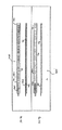
図1Aは、上述した送り込みシースの1つの変更例を示す切欠き側面図である。図1Aに最も良く示すように、シース100は、その長さの全体に亙って中央管腔104を保持する細長い軸102を備えている。シース100の作用長さは、末端部分110及び基端部分120を備えており、これら部分の各々は、以下に説明するような異なる可撓性を有する重合系材料を備えている。末端部分110に隣接して配置されたシース100の末端112は、作用長さも備えている。
Feed Sheath FIG. 1A is a cutaway side view showing one variation of the feed sheath described above. As best shown in FIG. 1A, the
シース100の基端近くにて、ハブ114を接着剤又はその他の適宜な手段により基端部分120に固定することができる。コネチカット州、ロッキーヒルのロックタイトコーポレーション(Loctite Corp.)がUV4201という名称で販売する紫外線硬化型接着剤を使用することが好ましい。また、コネチカット州、トローリングトンのダイマックスコーポレーション(Dymax corp.)からダイマックス(DYMAX)という商標名で販売されている接着剤を使用することが好ましい。ハブ114は、任意の適宜な医療等級ポリマーにて形成されており、また、射出成形し且つ、長手方向に折目を付け、又は目打線を設け、装置を乱さずにハブを装置の周りから除去し得るようにすることが好ましい。ハブを現場にて軸102の基端部分120に成形することができる。
Near the proximal end of the
ハブ114は、例えば、環状リングにより弁118の内径部に取り外し可能に固定される特殊な回転可能な止血弁(RHV)118を受け入れるのに十分に大きい開口部を有する。RHV118の中央管腔124は、軸102の管腔と整合され且つ、該管腔と流体的に連通している。管腔124は、バルーンカテーテル及びIS−1型コネクタのような典型的なリードコネクタを受け入れるのに十分に大きい直径を有する。選択的なサイドアーム(図示せず)を管腔124と流体的に連通する状態でRHV118に配置することができる。RHV118は、上述したように、折目を付け又は目打線を介して引裂くこともできる。
The hub 114 has an opening that is large enough to receive a special rotatable hemostatic valve (RHV) 118 that is removably secured to the inner diameter of the valve 118 by, for example, an annular ring. The central lumen 124 of the RHV 118 is aligned with the lumen of the
環状の重合系カラー116は、ハブ114がRHV118に合わさる箇所の基端側のRHV118の末端部分の外径部に配置されている。この実施の形態において、カラー116を回転させると、RHV118はハブ114に対して係止される。 The annular polymerization collar 116 is disposed on the outer diameter portion of the distal end portion of the RHV 118 at the base end side where the hub 114 meets the RHV 118. In this embodiment, when the collar 116 is rotated, the RHV 118 is locked against the hub 114.
図1Bは、図1Aの送り込みシースの断面図である。図1Bに示すように、末端部分110の軸102の断面図は、軸管腔104を明らかにする。軸102の内径は、その各々が管腔104を通り抜けることができなければならないバルーンカテーテル及びリードの外径に依存して変更することになろう。典型的に、軸の内径は、約2.03(0.080)ないし2.79mm(0.110インチ)の範囲にあり、より好ましくは、約2.49mm(0.098インチ)であるものとする。同様に、軸102の外径は、約2.29(0.090)ないし3.3mm(0.130インチ)の範囲にあり、より好ましくは、約3mm(0.118インチ)であるものとする。軸102の外径は、軸が使用される用途に従って許容可能な性能レベルを維持しつつ、可能な限り小さいことが好ましい。また、軸102が全体としてその長さの全体に亙って一定の内径を維持し、本明細書に記載した各種の装置及び材料が通るための滑らかで且つ、連続的な段無しの輪郭外形を提供するようにすることが好ましい。
FIG. 1B is a cross-sectional view of the delivery sheath of FIG. 1A. As shown in FIG. 1B, a cross-sectional view of the
末端部分110及び基端部分120を備える管は、典型的に、重合系であり、また、本明細書に記載した適宜な性能特性を有する任意の典型的な医療等級、生体適合性の管であることが好ましい。特に望ましい材料は、ペンシルベニア州、フィラデルフィアのアトケムノースアメリカインコーポレーテッド(Atochem North America,Inc.)が商標名ピーバックス(PEBAX)にて販売する型式の押出し成形したポリエステルブロックアミドである。 The tube comprising the distal portion 110 and the proximal portion 120 is typically a polymerization system and is any typical medical grade, biocompatible tube having the appropriate performance characteristics described herein. Preferably there is. A particularly desirable material is an extruded polyester block amide of the type sold by Atochem North America, Inc. of Philadelphia, Pennsylvania under the trade name PEBAX.
末端部分110及び基端部分120は、それぞれ、約20Dないし100D(ショア)の範囲のデュロメータ硬さを有する管にて製造される。軸102の作用長さは、2つ又はより多くの剛性を有する材料にて形成されることが好ましいが、その長さの全体に亙って単一の剛性値を有する軸102は、本発明の範囲に属するものである。
The distal portion 110 and the proximal portion 120 are each made of a tube having a durometer hardness in the range of about 20D to 100D (Shore). While the working length of the
1つの実施の形態において、基端部分120は、より可撓性の末端部分110(典型的に、約40D)と比較して相対的に高剛性値の材料(典型的に、約72D)を備えている。図1Bの図には図示しないが、末端部分110及び基端部分120は、テフロン(TEFLON)(デラウェア州、ウィルミントンのイー.アイ.デュポン・ドゥ・ヌムール アンド カンパニー(E.I. du Pont de Nemours and Company))ライナーにて編み上げたダクロン(DACRON)(デラウェア州、ウィルミントンのイー.アイ.デュポン・ドゥ・ヌムール アンド カンパニー)で出来たものとすることができる。編み上げ部は、上述したように、ピーバックス(PEBAX)管にて取り巻かれ、このことは、軸102の基端部分120は、末端部分110より全体としてより剛性で且つ非可撓性であるものにする。
In one embodiment, the proximal portion 120 is made of a relatively stiff material (typically about 72D) relative to the more flexible distal portion 110 (typically about 40D). I have. Although not shown in the view of FIG. 1B, the distal portion 110 and the proximal portion 120 are made of TEFLON (EI du Pont de Nemours and Company, Wilmington, Del.). (Nemours and Company)) liner knitted with DACRON (EA DuPont de Nemours and Company, Wilmington, Delaware). The braided portion is surrounded by a PEBAX tube, as described above, such that the proximal portion 120 of the
末端部分112は、血管壁の内膜又はその他の組織の損傷を防止し得るよう比較的低剛性の重合系材料で形成された柔軟な非外傷性先端であることが好ましい。末端112に対し有効な材料が判明した。末端に十分に適した材料は、ペレセン(PELLETHANE)(ミシガン州、ミッドランドのダウケミカルカンパニー(Dow Chemical Co.))等のような熱可塑性ポリウレタンエラストマーである。 The distal portion 112 is preferably a flexible atraumatic tip formed of a relatively low stiffness polymeric material to prevent damage to the intima or other tissue of the vessel wall. An effective material for the end 112 has been found. A well-suited material for the ends is a thermoplastic polyurethane elastomer such as PELLETHANE (Dow Chemical Co., Midland, Mich.).
本発明の1つの側面によれば、末端部分110は、放射線不透過性とすることができる。このことは、放射線不透過性金属又はその合金を構造体内に組み込むことにより、又はより好ましくは、BaSO、BiCO等のような放射線不透過性の粉体を末端部分110を構成するポリマー内に組み込むことにより実現することができる。末端部分112は、末端部分110よりも一層放射線不透過性であることが好ましい。このことは、より多量の放射線不透過性の粉体を例えば、管内に組み込むか又は、末端部分110にて使用されるものよりも大きい放射線不透過度を有する異なる材料を使用することで実現することができる。この放射線不透過性の特徴は、ユーザが蛍光透視法の下にてシース100のこれらの部分をより容易に視認化することを可能にする。
According to one aspect of the present invention, the distal portion 110 can be radiopaque. This may be accomplished by incorporating a radiopaque metal or alloy thereof into the structure, or more preferably, a radiopaque powder such as BaSO, BiCO, etc. is incorporated into the polymer comprising the end portion 110. Can be realized. The end portion 112 is preferably more radiopaque than the end portion 110. This is accomplished by incorporating a greater amount of radiopaque powder, for example, in the tube or using a different material that has a radiopacity greater than that used at the end portion 110. be able to. This radiopaque feature allows the user to more easily visualize these portions of the
軸102の全長(RHV118の末端112からより遠方の基端まで)は、典型的に、約40ないし60cm、好ましくは、約55cmである。末端112は、約0.2cmないし0.5cmの長さの範囲とすることができる一方、末端部分110は、全体として約5ないし10cmの範囲の長さであり、好ましくは、約8cmの長さであるものとする。基端部分120は、約35ないし50cmの長さの範囲にあり、好ましくは、約42cmであるものとする。 The total length of the shaft 102 (from the distal end 112 of the RHV 118 to the more distant proximal end) is typically about 40 to 60 cm, preferably about 55 cm. The distal end 112 can range in length from about 0.2 cm to 0.5 cm, while the distal portion 110 generally has a length in the range from about 5 to 10 cm, preferably about 8 cm long. It is assumed that Proximal portion 120 should be in the range of about 35 to 50 cm long, and preferably about 42 cm.
軸102及び取り付けられたハブ114の双方の作用長さは、その長手方向軸線に沿って目打線又は折目126を含むことができる。これと代替的に、これらは、また引裂き可能な形態とし、シース100を装置に対して軸方向に摺動させることを必要とせずに、開放し、また、リード又は電気生理学的カテーテルのような挿入された装置の周りから除去することができるようにしてもよい。特殊な工具を使用してかかる引裂きを容易にし、又はシース/ハブ(更にRHV114)の結合体は、何ら特殊な装置の助けを受けずに手で引裂くことができる。リー(Lee)に対する米国特許第5,312,355号に記載されたような引裂き可能な弁及びシースの結合体はその一例である。
The working length of both the
バルーンカテーテル
次に、図2A及び図2Bを参照すると、本発明のバルーンカテーテル200が側面図及び末端の断面図にてそれぞれ図示されている。このカテーテルは、大部分、各々、その内容の全体を参考として引用し本明細書に含めた、ランドルフらに対する米国特許第6,021,340号及び米国特許第5,775,327号に開示された案内カーテル及びカリフォルニア州、フレモントのカルディマインコーポレーテッド(Cardima,Inc.)から販売されているバルーン閉塞案内カテーテルのヴューポート(VUEPORT)製品群のものと同様である。
Balloon Catheter Referring now to FIGS. 2A and 2B, a
カテーテル200は、展開シース100の中央管腔104を通り抜け且つ、シース100及び偏向機構300の結合した装置として治療箇所に達するような設計とされている。
図2A及び図2Bに示すように、バルーンカテーテル200は、全体として、細長い軸202と、末端軸部分204と、基端軸部分206と、内管腔208とを有している。雌型ルアロック210は、軸202の基端に配置し且つ、紫外線硬化型ロックタイト(Loctite)4201のような適宜な接着剤212により固定することができる。
The
As shown in FIGS. 2A and 2B, the
末端ポート214が内管腔208と流体的に連通したカテーテル軸の末端216に設けられている。末端216の基端側には、カテーテル軸202の周りにて末端部分204に軸方向に配置された閉塞バルーン211がある。カテーテル軸202には、軸202を通ってバルーン211の内部まで伸びてその内部に拡張流体を導く拡張管腔209が設けられている。
A distal port 214 is provided at the distal end 216 of the catheter shaft in fluid communication with the
ルアロック210の基端側のカテーテル200の基端には、Y−アダプタ又は止血弁232にて終わる多数アームアダプタ又はハブ222と、以下に説明するように、偏向機構が通るための基端側ポート218とがある。
At the proximal end of the
アダプタ222における第一のサイドアーム又はポート224(図2Aに部分断面図にて図示)が拡張流体を拡張管腔209内に導入するのを容易にする。適正な量の流体(空気のような)が注射器230を介して導入されたならば、バルーン221が拡張した状態に留まるのを許容する第一のサイドアーム224におけるコック栓228がコック栓228に隣接して配置されている。拡張管腔209は、ポート224内に配置され且つ、上述したように、軸224内に末端方向に伸びてバルーン211が拡張し易いようにする。
A first side arm or
また、第二のサイドアーム又はポート226をハブ222に配置し、大きい内管腔208と直接、流体的に連通させることができる。偏向機構等のような装置を収容するため、内管腔208が使用される。バルーン211が拡張したならば、第二のポート226を使用して造影媒体又は同様の材料を管腔208を通じて且つ、末端ポート214から導入して、例えば、臓器の内腔又は心臓静脈系のような対象とする身体部分を視認化することができる。
A second side arm or
図示されていないが、基端側の中央ポート218内に収容し且つ、以下に説明する偏向機構のような装置を受け入れることのできる回転可能な止血弁(RHV)がある。このRHVは、偏向機構に対し密封して流体の漏洩を防止することができ、また、単一のRHV及び2つのサイドポートを備えるように形態変更されたデュオスタット(duostat)の一部とすることができる。勿論、その他の形態とすることが可能である。
Although not shown, there is a rotatable hemostatic valve (RHV) housed in the proximal
バルーンカテーテル200の軸202は、十分な寸法であり、該カテーテルはシース100の管腔104を容易に通り抜けることができる。理想的には、軸202の外径は、約1.27mm(0.050インチ)ないし2.54mm(0.100インチ)の範囲にあることが好ましい。より好ましくは、この外径は、1.52mm(0.060インチ)ないし2.03mm(0.080インチ)の範囲にあり、最も好ましくは、約1.88mm(0.074インチ)であるものとする。
The
内管腔208の直径は、造影媒体又はその他の材料が自由に通るのを許容するのに十分に大きく、静脈造影図及び同様の診断方法を容易に行うことができるようにすることが好ましい。該直径は、また、以下により詳細に説明するように、偏向機構が通り抜けるのに十分に大きくなければならない。最後に、管腔208は、偏向機構のような装置が存在する間、造影媒体又はその他の剤が自由に通るのを許容しなければならない。一般に、内管腔は、約0.762mm(0.030インチ)ないし2.03mm(0.080インチ)の範囲、好ましくは、約1.22mm(0.048インチ)の直径を有することが好ましい。同様に、拡張管腔209は、約0.127mm(0.005インチ)ないし0.508mm(0.020インチ)の範囲、好ましくは、約0.356mm(0.014インチ)の直径を有することが好ましい。
The diameter of the
バルーンカテーテル軸202は、約60Dないし80Dの範囲、好ましくは、約72Dのデュロメータ硬さを有するピーバックス(PEBAX)管を備えることが好ましい。好ましくは、軸の基端部分206は、その外面に配置された熱シュリンク管を有するものとする。好ましくは、この熱シュリンク管は、重合系であり且つ、透明なポリオレフィン等から成るものとする。末端先端216は、シース100の末端先端112と組成及び剛性の点にて同様である、比較的可撓性の重合系材料で出来た柔軟で非外傷性の先端であることが好ましい。
末端先端216、末端部分204及び基端部分206を含む、バルーンカテーテル軸202の作用長さは、約50cmないし90cmの範囲でなければならないが、この作用長さは、用途に依存してより長くし又は短くすることができる。約0.5cmの末端先端216、約6cmの末端部分204及び約63.5cmの基端部分206を受け入れることのできる、約70cmの作用長さであることが好ましい。
The working length of the
この実施の形態におけるカテーテル200の全体の長さ(軸202及び上述した基端部分206の基端側に配置された構成要素の作用長さ)は、約77.5cmでなければならない。一般に、バルーンカテーテル軸202は、シース100よりも約15cmないし20cmだけ長いことが好ましい。
The overall length of the
勿論、カテーテル200の構成要素の各々の絶対的長さ及び相対的長さは顕著に相違する。本発明のカテーテル200及びシステムの全体が使用される特定の用途によって、本明細書に記載したその各種の構成要素(及び本発明のシステムの構成要素の各々)に対する特定の寸法及び材料が決まることになろう。
Of course, the absolute length and relative length of each of the components of the
閉塞バルーン211は、拡張したとき、冠状静脈洞口を密封するのに十分な直径を有しなければならない。この拡張した直径は、典型的に、約5.08mm(0.2インチ)ないし25.4mm(1.0インチ)の範囲にあり、より好ましくは、約10.2mm(0.4インチ)ないし20.3mm(0.8インチ)の範囲にあるものとする。バルーン211は、非弾性的又は弾性的重合系材料を備えることが好ましい。ポリウレタン(例えば、フロリダ州、マイアミのワールドメディカルインコーポレーテッド(World Medical,Inc.)の80Aデュロメータのペレセン(PELLETHANE))であることが好ましい。非拡張状態のバルーン211の内径は、典型的に、約1.02mm(0.04インチ)ないし2.03mm(0.08インチ)の範囲にあり、より好ましくは、約1.42mm(0.056インチ)ないし1.78mm(0.070インチ)の範囲にあるものとする。バルーンの肉厚は、典型的に、約0.0508mm(0.002インチ)ないし0.152mm(0.006インチ)の範囲にあり、より好ましくは、約0.102mm(0.004インチ)であるものとする。最後に、バルーン211の長さは、典型的に、約6mmないし14mmの範囲にあり、より好ましくは、約8mmないし12mmの範囲にあるものとする。
The
偏向機構及びマイクロ偏向機構
偏向機構及びマイクロ偏向機構は、本発明の2つの別個の構成要素である。偏向機構300は、バルーンカテーテル200内で使用し得る設計とされており、多くの点にて、マイクロ偏向機構400と同様であり、より大形である点にて相違するに過ぎない。マイクロ偏向機構400は、リード、電気生理学的カテーテル又はその他の同様のIMDsのような装置を正確に制御し且つ偏向させることが必要とされる多岐に亙る用途にて使用可能な設計とされている。偏向機構300に比してその寸法が小さい結果、該機構は、その小さい寸法及び可撓性が活用される広範囲の用途にて使用可能である。
The deflection mechanism and the micro deflection mechanism The deflection mechanism and the micro deflection mechanism are two separate components of the present invention. The
図3は、偏向機構及びマイクロ偏向機構の双方の構成要素を示す平面図であるが、説明の目的のため、偏向機構300に関して説明する。偏向機構300は、全体として、基端部分304、末端部分306及び末端先端308を備えている。その1つの好ましい改変例を図4A及び図4Bに詳細に示したハンドル310が基端部分304に隣接している。
FIG. 3 is a plan view showing components of both the deflection mechanism and the micro deflection mechanism. For the purpose of explanation, the
偏向機構300は、バルーンカテーテル200の基端ポート218を通じ且つ内管腔208内に配置し得る設計とされており、偏向機構の末端先端308は、全体として、バルーンカテーテル軸202の末端部分204、及び好ましくは、末端先端216に達するようにされている。ハンドル310を作用させたとき、偏向機構300の末端部分306は、所定の仕方にて偏向し、これにより、同様の仕方にてバルーンカテーテルの末端部分204を偏向させる。このようにして、バルーンカテーテル200(又は偏向機構300がその内部に配置される任意の装置)にトルクを加えて、カテーテルがその内部に配置される特定の管腔又はキャビティに順応するようにすることができる。
The
偏向機構300の軸302は、医療等級ステンレス鋼、チタン、ニチノール、これらの合金又は当該技術分野の当業者に既知の任意の適宜な材料のような生体適合性金属材料で出来ていることが好ましい皮下管312のような管状部材を備えている。皮下管312は、カテーテル200の内管腔208内に嵌まるのに十分に小さく、好ましくは、1.22mm(0.048インチ)以下の外径を有することが好ましい。図3に示すように、皮下管312は、皮下管312の末端に歪み除去部分316を形成し得るよう斜角面付きとされている。勿論、この皮下管312の特定の形態及び図3の偏向機構300のその他の特徴は、単に一例にしか過ぎないものである。本発明の目的を達するその他の形態は、同様に、本開示の範囲に属する。
The shaft 302 of the
皮下管312の中央管腔内に配置されているのは、引っ張りワイヤー320であり、該引っ張りワイヤーは、引っ張られたとき、偏向機構300の末端部分306を偏向させるステンレス鋼、チタン、ニチノール又はその他の金属又は合金或いは重合系ワイヤーさえとすることもできる。引っ張りワイヤー320は、偏向機構300の末端部分306内に配置された平形ばね322に取り付けられる。ばね322は、溶接、ブレージング、はんだ付け、接着剤又は当該技術分野の当業者に既知の同様のもののような任意の適宜な取り付け方法を使用して皮下管312に取り付けられる。ばね322は、図3に示すように、ブレーズ領域314に沿って皮下管312にブレーズすることができる。同様に、引っ張りワイヤー320をばね322に取り付けるため任意の同様の適宜に取り付け技術を使用することができる。1つの実施の形態において、引っ張りワイヤー及びばねは、図3に示すように、ブレーズ領域318内で互いにブレーズされる。
Disposed within the central lumen of hypotube 312 is a
末端の偏向領域306は、ポリエステル、PEBAX及びテトラフルオロエチレンのような柔軟な重合系医療等級管にて覆われることが好ましい。特に好ましいのは、その頭文字によってTHVとして知られるテトラフルオロエチレンヘキサフルオロプロピレン及びフッ化ビニリデンのポリマーである。これは、流体が偏向機構内に浸透するのを防止する。
The
リードを植え込むためにシステムが使用される、本発明の特に有用な変更例において、バルーン偏向機構300は、冠状静脈洞口内に導入する間、バルーンカテーテル200に対し剛性を付与するのに十分な直径のものである。曲線の到達距離及び偏向範囲は、冠状静脈洞口内に容易に導入するのに十分なものであり0、また組立体の全体は、冠状静脈洞口内に入れる操作をする間、バルーンカテーテル軸202の末端部分204を偏向させ且つトルクを加えるのに十分な引張り強度を提供しなければならない。
In a particularly useful variation of the invention where the system is used to implant a lead, the
次に、図4A及び図4Bを参照すると、偏向機構300を操作するハンドル310の有用な変更例が示されている。ハンドル310は、本体324及び作動機構326を有している。作動機構326は、ハンドル310の長手方向軸線に沿って末端方向に押すか、又は基端方向に引っ張ることにより操作することができる。これら構成要素の機械加工部品は、重合系のものとすることができる。例えば、アセチルホモポリマーデルリン(DELRIN)(デラウェア州、ウィルミントンのイー.アイ.デュポン・ドゥ・ヌムール アンド カンパニー)のような熱可塑性剤をこの目的のために使用することができる。成形した部品は、ABS(アクリロニトリルブタジエンスチレン)等のような重合系材料で形成することができる。引っ張りワイヤー320の基端は、ハンドル310の中央管腔328内に配置し且つ、当該技術分野の当業者に既知の手段によってハンドル内に固定することができる。
4A and 4B, a useful modification of the
ハンドル310は、軽量であり且つ、簡単に片手で操作可能な人間工学的な形態とされることが好ましい。偏向範囲(直線状で且つ偏向前の0゜の位置から変位されたとき、末端先端308が受ける最大の変位角度)は、約90゜ないし180゜の範囲とし、好ましくは、約100゜ないし135゜の範囲とすることができる。末端部分306の特徴及び多機能性の更なる詳細については、以下に詳細に説明し、また、偏向方法の詳細な説明にて記述する。
The
図5は、上述した本発明のシステムの3つの構成要素の部分断面図である。ハンドル310を有する偏向機構300は、上述したように、基端ポート218を介してバルーンカテーテル軸202の内管腔に配置した状態で示されている。一方、偏向機構300及びバルーンカテーテル200の結合体は、シース100の管腔104内に配置されている。図5において、バルーンカテーテル軸202の末端部分は、皮下管/引っ張りワイヤー機構の作用を介して収縮した状態で示してある。末端バルーン211は、バルーン流体ポート224を通じて提供された流体にて拡張されていることが分かる。本明細書にて説明したように、外側引裂きシース100に対するRHV118は、RHV118に配置された洗浄ポート130として見ることができる。明確化のため、シースハブ114は図示していない。
FIG. 5 is a partial cross-sectional view of the three components of the inventive system described above. The
全体として、本明細書に記載した偏向機構の寸法に何ら制限はない。関係した構成要素の全ては、当該技術分野の当業者に明らかであるように、また、特定の用途が要求するように、本明細書に開示されたものよりも大きい又は小さい寸法に容易に調節することができる。 Overall, there are no restrictions on the dimensions of the deflection mechanism described herein. All of the components involved are easily adjusted to larger or smaller dimensions than those disclosed herein, as will be apparent to those skilled in the art and as required by the particular application. can do.
次に、図3に全体として図示したマイクロ偏向機構400についてより具体的に説明するが、この要素の特徴は、全体として偏向機構300のものと同様である。特徴部は、全体としてより小さく、このため、これらの特徴は、以下に説明するようなリード、電気生理学的カテーテル及び同様のもののような装置内で使用することができる。
Next, the
マイクロ偏向機構は、図7A、図7B、図8Aないし図8Eに示した皮下管の形態を利用する。マイクロ偏向機構の皮下管(図示せず)の外径が約0.305mm(0.012インチ)ないし0.762mm(0.030インチ)の範囲にあり、好ましくは、約0.356mm(0.014インチ)ないし0.66mm(0.026インチ)の範囲、最も好ましくは、約0.381mm(0.015インチ)であることが好ましい。このことは、皮下管を従来のIS−1リードコネクタ内に導入するのを許容し且つ、リード又はカテーテルの構成要素の何れかに不当な応力又は損傷を与えずに、皮下管をリード本体の中央管腔の全長内で動かすことを許容する。 The micro deflection mechanism utilizes the form of the hypodermic tube shown in FIGS. 7A, 7B, and 8A to 8E. The outer diameter of the hypodermic tube (not shown) of the micro-deflection mechanism is in the range of about 0.012 inch to 0.030 inch, preferably about 0.356 mm (. 014 inches) to 0.66 mm (0.026 inches), most preferably about 0.015 inches. This allows the hypodermic tube to be introduced into a conventional IS-1 lead connector and does not cause undue stress or damage to either the lead or the catheter components, and allows the hypodermis to be inserted into the lead body. Allow movement within the full length of the central lumen.
ステンレススチール又はニチノールであることも好ましいマイクロ偏向機構400の引っ張りワイヤーが0.127(.005)ないし0.381mm(.015インチ)の範囲、より好ましくは、約0.152mm(.006インチ)ないし0.254mm(0.010インチ)の範囲の外径を有することも好ましい。最も好ましくは、外径は、約0.203mm(0.008インチ)であるものとする。
The pulling wire of the
偏向する間、組立体400の最末端の10mmないし30mmが偏向することが好ましく、このことは、好ましい適用例において、組立体400がその内部に配置されるリードが冠状静脈洞口に係合することを許容する。寸法が小さく且つ一層操作可能であるため、組立体400は、360゜、更に、450゜以上の角度に亙ってさえ偏向可能である。かかる大きい角度で偏向し得ることは、機構400(及び機構をその内部に展開させることのできる装置)が緊密なループを形成することを許容する。これらの大きい角度の偏向は、マイクロ偏向機構400をマッピング/アブレーションマイクロカテーテル内で展開させ、心臓肺静脈のような領域内で周方向アブレーションパターン等を形成することのできる電気生理学的用途にて特に有用なことである。
During deflection, it is preferred that the most distal 10 mm to 30 mm of the
図6Aないし図6Dには、マイクロ偏向機構400のハンドル414の特に有用な変更例の各種の構成要素が示されている。図6Aに示すように、ハンドル414は、本体416と、ハンドル310の長手方向軸線に沿って末端方向に押し又は基端方向に軸方向に引っ張ることにより操作することのできる作動機構418とを有している。ハンドルは、約5.08cm(2インチ)の範囲とすることのできる比較的短い長さである。この長さは、マイクロ偏向機構400のその他の小さい構成要素と良好に調和し、また、外科医が簡単に片手の指先で操作することを許容する。勿論、これら寸法は、上述した仕方にて必要に応じて設定することができる。
6A-6D show various components of a particularly useful variation of the handle 414 of the
マイクロ偏向機構400は、全体として偏向可能なリード又はカテーテルを提供するために使用される固定湾曲スタイレットに置換すべく使用することができる。この偏向可能なリード又はカテーテルは、心臓静脈系の標的領域内に一層正確に配置し、従来の技術の問題点を解決することができる。更に、マイクロ偏向機構は、偏向可能な電気生理学的カテーテルに関して本明細書に説明した本発明のシース及びその他の構成要素と組み合わせて使用することができる。
The
偏向機構300及びマイクロ偏向機構400(この総称的な説明のため、以下に単に「偏向機構」と称する)の双方に共通する特徴について説明するが、これら特徴の各々は、皮下管/引っ張りワイヤーの組立体に基づいて同一の原理にて作用する。引っ張りワイヤーは、皮下管の中間を貫通して伸び且つ、偏向機構の末端にブレージング等を介して取り付けられる。
Features common to both
皮下管は、皮下管の末端部分に切り込んだ一連のスロット又は目打線により所定のパターンにて偏向することが許容される。その各々の内容の全体を参考として引用し本明細書に含めた、サベイジ(Sabage)らに対する米国特許第5,507,725号、双方とも、アヴィトール(Avitall)に対する米国特許第5,921,924号、米国特許第5,441,483号、スノウスキー(Snowski)らに対する米国特許第4,911,148号、パスカー(Paskar)に対する米国特許第5,304,131号には、幾つかの型式の切欠きを使用して偏向させる各種の医療装置が記載されている。 The hypotube is allowed to deflect in a predetermined pattern by a series of slots or perforations cut into the distal portion of the hypotube. U.S. Pat. No. 5,507,725 to Sabage et al., Both of which are incorporated herein by reference in their entirety, both U.S. Pat. No. 5,921,924 to Avitall. US Pat. No. 5,441,483, US Pat. No. 4,911,148 to Snowski et al., US Pat. No. 5,304,131 to Paskar, Various medical devices are described that deflect using a notch.
図7及び図8には、本発明にて使用可能な切欠きパターンの2つの変更例が示されている。これら特徴の調節可能性のため、これら特徴は、偏向組立体300及びマイクロ偏向組立体400の双方に使用可能である。
7 and 8 show two modified examples of notch patterns that can be used in the present invention. Because of the adjustable nature of these features, these features can be used in both the
図7及び図8及び以下の説明に関連して、図面のスペース上の制約のため、皮下管の「基端部分」とは、相応する末端部分の基端側に配置されるという点においてのみ基端側である偏向機構の一部を意味するものであることを認識すべきである。図7及び図8に示した皮下管のかなりの長さは、そのように標識された「基端部分」の基端側に出ることも可能である。 In connection with FIGS. 7 and 8 and the following description, due to space constraints in the drawings, the “proximal portion” of the hypodermis is only in that it is located proximal to the corresponding distal portion. It should be recognized that it refers to a portion of the deflection mechanism that is proximal. A considerable length of the hypotube shown in FIGS. 7 and 8 can also emerge proximally of the “proximal portion” so labeled.
図7A及び図7Bにおいて、2つの皮下管/引っ張りワイヤーの結合体がそれぞれページの最上部から開始する頂面図及び側面図に示されている。図7Aには、引っ張りワイヤー704が皮下管の末端部分708にて皮下管702の末端にブレーズ、はんだ付け又はその他の方法で固定される組立体700が示されている。引っ張りワイヤー704は、皮下管702内に配置されていることを認識すべきである。引っ張りワイヤーは、皮下管の末端部分708まで全経路に亙って皮下管702の内部に配置されており、該皮下管の末端部分にて引っ張りワイヤーは、上述したように皮下管702に固定されている。全体として、引っ張りワイヤー704はハンドル310内に固定され、ハンドルを作用させたとき、皮下管の末端部分708は、切欠き710(又は以下に説明するように、皮下管の縮小した肉厚)が配置される側と同一の側にて偏向することになろう。
7A and 7B, two hypotube / pull wire combinations are shown in a top view and a side view, respectively, starting from the top of the page. FIG. 7A shows an assembly 700 in which a pull wire 704 is blazed, soldered, or otherwise secured to the distal end of the hypotube 702 at the
切欠き又は切目710の各々は、皮下管702の基端706から末端708まで移動するのに伴い漸進的に深くなる。この特定の特徴により、皮下管は滑らかな一定の曲線にて偏向することになる。切欠き710の間の間隔は一定であり、その深さを変化させるのは、切欠き710の寸法のみであることを理解すべきである。幅は一定のままである。これらパラメータの各々は、性能が要求するように変更することができる。
Each notch or cut 710 progressively deepens as it moves from the proximal end 706 to the
更に、切欠きの各々の中心は、基端部分706から末端部分708まで移動するのに伴い単一の直線状ライナーの長手方向軸線に沿って整合される。切欠きが整合されるこの軸線は、非直線状とすることができる。例えば、軸線は、一定の又は変化するピッチを有する蛇行した偏向輪郭外形を実現し得る正弦波状とし又は軸線は、何らかのその他の曲線状又は段階状の形状とすることさえもできる。切欠きの中心が直線状又は非直線状の軸線に沿って整合されるかどうかに関係なく、切欠きの各々の中心がかかる軸線に沿って1列に並ぶ必要はない。
Further, the center of each notch is aligned along the longitudinal axis of a single linear liner as it moves from the proximal portion 706 to the
隣接する切欠きの間の距離は、1つの切欠きの一端から図7Aの皮下管の他端まで移動するのに伴い、一定のままであることも認識すべきである。すなわち、切欠きの長手方向軸線は互いに平行である。切欠き又は切目のこの特徴は、用途に対応して変更することもできる。 It should also be appreciated that the distance between adjacent cutouts remains constant as it moves from one cutout end to the other end of the hypotube in FIG. 7A. That is, the longitudinal axes of the notches are parallel to each other. This feature of the notch or cut can also be changed depending on the application.
組立体700の形状及び性能特徴に影響を与える別の変数は、切欠き710が皮下管に切り込まれる深さである。例えば、図7A及び図7Bの組立体において、切欠きは、皮下管702の肉厚に完全に切り込まれる。これは、必ずしも必要な訳ではない。皮下管の厚さに貫入せずに皮下管から別個の量の材料を除去する切欠きを皮下管702に提供することは本発明の範囲に属する。このため、切欠きの各々をエッチングするとき、多岐に亙る深さ輪郭外形及びパターンとすることが考えられる。 Another variable that affects the shape and performance characteristics of the assembly 700 is the depth at which the notch 710 is cut into the hypotube. For example, in the assembly of FIGS. 7A and 7B, the notch is completely cut into the thickness of the hypotube 702. This is not always necessary. It is within the scope of the present invention to provide a notch in the hypotube 702 that removes a discrete amount of material from the hypotube without penetrating the thickness of the hypotube. For this reason, when etching each of the notches, it is conceivable to have various depth contours and patterns.
この着想を更に一段階進めるため、皮下管702は、所望の好ましい距離の偏向形状及び応答性を実現し得るよう一連の切欠き又は切目を保持する必要はない。例えば、引っ張りワイヤー704を作用させたとき、皮下管702の末端部分708が所定のパターンにて偏向するように、皮下管702の全体を非対称の仕方にて優先的に機械加工し又はエッチングすることは本発明の範囲に属することである。換言すれば、皮下管702の肉厚は、単純なテーパー付きのパターンから相応する精緻で且つ複雑な偏向形状及びリソースが得られる複雑なパターンの範囲に亙るパターンにて長さ及び(又は)周方向位置の関数を変化させ得るようにすることができる。かかる着想は、単独にて又は本明細書に記載したように、切欠き又は目打線と組み合わせて使用することができる。
To take this idea one step further, hypotube 702 need not hold a series of notches or cuts to achieve the desired preferred distance deflection shape and responsiveness. For example, the entire hypotube 702 is preferentially machined or etched in an asymmetric manner so that the
上述したパラメータ及び皮下管の肉厚、材料の選択等のようなその他のパラメータの各々は、皮下管/引っ張りワイヤー組立体(組立体700のような)が意図する適用例に依存して特定の偏向パターン又は応答性を実現し得るように選ぶことができる。更に、これらパラメータの多数を切欠き毎に変化させることも可能である。例えば、1つの切欠きは矩形の輪郭外形を有し、同一の皮下管の別の切欠きは、円形の輪郭外形を有する等とすることができる。 Each of the parameters described above and other parameters such as hypotube thickness, material selection, etc. are specific depending on the application for which the hypotube / pull wire assembly (such as assembly 700) is intended. A deflection pattern or responsiveness can be selected. It is also possible to change many of these parameters from notch to notch. For example, one notch may have a rectangular outline and another notch of the same hypodermic tube may have a circular outline.
所望の偏向形状を与えられた皮下管702に対する最適な輪郭外形を確認するため、数学的アルゴリズム等を介して設計者を助けるためソフトウェアを利用することができる。例えば、設計者は、組立体を使用すべき用途を選ぶことができ、またソフトウェアは、設計者が選ぶことができる多数の代替的な形状を選ぶことができる。1つの偏向形状が選ばれたならば、次に、ソフトウェアは、最適な皮下管の輪郭外形を計算することになろう。 Software can be used to assist the designer, such as through a mathematical algorithm, to ascertain the optimum contour profile for the hypodermic tube 702 given the desired deflection shape. For example, the designer can choose the application in which the assembly should be used, and the software can choose a number of alternative shapes that the designer can choose. If one deflection shape was chosen, then the software would calculate the optimal hypodermic contour.
図7Bには、皮下管752及び引っ張りワイヤー754が上述し且つ図7Aに示したものと同様の仕方にて配置される組立体750が示されている。図7Bの組立体の唯一の相違点は、切欠き756間の一定の間隔が図7Aの組立体の場合よりも大きい点である。切欠き756間の間隔がこのように増大するが、一定である結果、皮下管から切除される材料が少ないから、皮下管752の重量が僅かにより重くなる。組立体750が偏向したとき、このことは、末端部分760が所定の偏向力に対し図7Aの組立体700が経験するよりも大きい湾曲直径の小さい角度にて偏向することを意味する(偏向形状は、全体として、各組立体における切欠きの寸法、形状及び向きが同様であるため、偏向した組立体700のものと同様ではあるが)。 FIG. 7B shows an assembly 750 in which the hypotube 752 and the puller wire 754 are arranged in a manner similar to that described above and shown in FIG. 7A. The only difference in the assembly of FIG. 7B is that the constant spacing between the notches 756 is greater than in the assembly of FIG. 7A. The spacing between the notches 756 thus increases, but as a result of the constant, the weight of the hypotube 752 is slightly heavier because less material is removed from the hypotube. When the assembly 750 is deflected, this means that the distal portion 760 deflects at a small angle with a larger curvature diameter than the assembly 700 of FIG. 7A experiences for a given deflection force (deflection shape). Is generally similar to that of the deflected assembly 700, since the size, shape and orientation of the notches in each assembly are similar).
次に、図8Aないし図8Eを参照すると、切欠きパターンの追加的な変更例が示されている(明確化のため、引っ張りワイヤーは省略)。図8Aにおいて、基端部分812及び末端部分814を有する皮下管810は、切欠き816の端部の各々が全体として切欠き816に対し垂直に向き決めされた第二の切欠き818を有する点を除いて、図7A及び図7Bのものと同様の一連の直線状切欠き816を保持している。この切欠きの設計により、皮下管810の末端部分814は、上述したように、同様の仕方にて但しよりきつい湾曲直径にて偏向することになる。 Referring now to FIGS. 8A through 8E, additional modifications of the notch pattern are shown (the pull wire is omitted for clarity). In FIG. 8A, a hypotube 810 having a proximal portion 812 and a distal portion 814 has a second notch 818 in which each of the ends of the notch 816 is generally oriented perpendicular to the notch 816. Except for a series of straight notches 816 similar to those of FIGS. 7A and 7B. This notch design will cause the distal portion 814 of the hypotube 810 to deflect in a similar manner but with a tighter curved diameter, as described above.
図8Bの皮下管は、切欠きパターンが皮下管820の基端部分822により近い箇所から開始する点を除いて、図8Aのものと同一である。このため、引っ張りワイヤーによって作動されたとき、皮下管のより長い末端部分824が偏向する。 The hypodermic tube of FIG. 8B is the same as that of FIG. 8A except that the notch pattern starts at a location closer to the proximal end portion 822 of the hypodermic tube 820. Thus, when actuated by a pull wire, the longer end portion 824 of the hypodermic tube deflects.
図8Cは、切欠きが非直線状の仕方にて配置される偏向機構の1つの実施の形態を示す平面図である。例えば、正弦波状パターンが示されているが、その他の多くの型式のパターンが可能である。 FIG. 8C is a plan view showing one embodiment of a deflection mechanism in which the notches are arranged in a non-linear manner. For example, although a sinusoidal pattern is shown, many other types of patterns are possible.
図8Dは、切欠きが異なる形状及び寸法である偏向機構の1つの実施の形態を示す平面図である。例えば、切欠きは、引っ張りワイヤーに張力が加えられたとき、偏向機構が所望の形状をとることを許容し得るように望まれる円形、三角形、矩形又は任意のその他のパターンをとることができる。切欠きは、全て均一な形状及び寸法を有するか、又は代替的に異なる形状及び(又は)寸法を有するようにすることができる。 FIG. 8D is a plan view showing one embodiment of a deflection mechanism with different shapes and dimensions of notches. For example, the notch can take a circular, triangular, rectangular, or any other pattern that is desired to allow the deflection mechanism to assume the desired shape when tension is applied to the puller wire. The notches can all have a uniform shape and dimensions, or alternatively can have different shapes and / or dimensions.
図8Eは、皮下管が一定の厚さではない壁を有する偏向部材の1つの実施の形態を示す断面図である。壁のより薄い領域は、引っ張りワイヤーに張力が加えられたとき、1つの好ましい曲げ方向を画成する。1つの実施の形態において、薄い肉厚であること及び薄い領域内に切欠きを形成することの双方を使用して皮下管又はその他の管状部材に偏向機構を提供することができる。 FIG. 8E is a cross-sectional view illustrating one embodiment of a deflection member having a wall where the hypotube is not of a constant thickness. The thinner area of the wall defines one preferred bending direction when tension is applied to the puller wire. In one embodiment, both the thin wall thickness and the formation of a notch in the thin area can be used to provide a deflection mechanism for the hypotube or other tubular member.
本明細書に記載し且つ、図面に示した切欠き又は目打線並びに皮下管の相違する肉厚は、当該技術分野の当業者に既知の任意の手段により形成することができる。これらは、従来のレーザ、電気放電又は同様の機械加工方法により機械加工し、また、化学的にエッチングし、又は、既知のフォトリソグラフィック技術等を使用してエッチングすることができる。 The notches or perforations and the different thicknesses of the hypodermic tube described herein and shown in the drawings can be formed by any means known to those skilled in the art. These can be machined by conventional laser, electrical discharge or similar machining methods, chemically etched, or etched using known photolithographic techniques and the like.
本明細書に記載した偏向機構の特に有用な特徴は、偏向機構ハンドル(ハンドル310及びハンドル414の双方)を能動的に制御する特徴である。ハンドルの作動機構が上述したように係合して末端部分を偏向させたならば、同一の作動機構を非係合状態にするユーザの確実な入力だけで逆方向に偏向させることができる。上述し且つ図4Aないし図4B及び図6Aないし図6Dに示した偏向機構の1つの実施の形態において、これらの機構が展開された後に作動機構326、418を解放する結果、末端部分は、偏向された状態に留まることになる。この逆の偏向状態とするためには、外科医−ユーザは作動機構を引込ませることを必要とし、そのとき、末端部分306は、ハンドルが再度作用させる迄、非偏向状態にある。この特徴により、バルーンカテーテル200の末端部分204が、例えば所望の偏向又は非偏向状態にある間、外科医−ユーザは、本発明のシステムのその他の部分を操作し、又はその他の作業を行うことができる。勿論、末端部分を偏向させる作動が自動的に逆になって末端部分を不作動の非偏向状態に戻すようにハンドルを設計することも本発明の範囲に属することである。このことは、外科医が最初の偏向を生じさせる確実な入力を解放したときに作動する偏倚ばね又は同等の機構により行うことができる。かかる設計は、また偏向機構の末端を偏倚させ、不作動の偏向状態に自動的に逆になるようにすることもできる。
A particularly useful feature of the deflection mechanism described herein is the feature that actively controls the deflection mechanism handle (both handle 310 and handle 414). If the handle actuating mechanism is engaged as described above to deflect the distal end portion, it can be deflected in the opposite direction with only the user's reliable input to disengage the same actuating mechanism. In one embodiment of the deflection mechanisms described above and shown in FIGS. 4A-4B and 6A-6D, releasing the
ハンドル310、414の双方に共通する別の特徴は、ハンドル内に組み込むことのできる1つ又はより多数の制限ストッパが存在する点である。これらの制限ストッパは、偏向機構の過偏向を防止し得る設計とされている。
Another feature common to both
心臓リードの展開
次に、図9ないし図11を参照すると、本明細書に記載したシステムの特に有用な適用例が示されており、これについて以下に説明する。特に、システムを冠状静脈洞内に血管内展開させる方法、閉塞性静脈造影図を得て、また、静脈支管を正確に二次的に選び及び且つその内部に心臓リードを配置する方法について説明する。
Cardiac Lead Deployment Referring now to FIGS. 9-11, a particularly useful application of the system described herein is shown and described below. In particular, a method for intravascular deployment of the system into the coronary sinus, obtaining an occlusive venogram, and a method for accurately selecting a secondary branch and placing a cardiac lead therein is described. .
この手順を準備するため、バルーンカテーテル200を外側シース100の管腔104内に挿入してシース/カテーテルの結合体を形成する。偏向機構300を基端ポート218を介してバルーンカテーテルの大きい管腔208内に前進させ、偏向機構の軸308の末端先端308が全体として、上述したように軸の末端先端216付近にてバルーンカテーテル軸202内に配置されるようにする。このことは、図5に示すように、シース/カテーテル/偏向機構の結合システムを形成する。典型的に、シース202の一部分は、ある長さに亙ってシース100の末端112にて管腔104を貫通し且つ、管腔104を越えて伸びる。
To prepare for this procedure, the
この3つの構成要素から成るシステムを橈側皮静脈、鎖骨下静脈を通じて又は当該技術分野の当業者に既知であるように従来の導入器を介して大腿部静脈を通じて患者の静脈系内に導入する。外科医は、導入器を使用して選んだ静脈を拡張させ、次に、システムを導入器を通じて選んだ静脈内に前進させる。 The three component system is introduced into the patient's venous system through the cephalic vein, the subclavian vein, or through the femoral vein via a conventional introducer as known to those skilled in the art. . The surgeon uses the introducer to dilate the selected vein and then advances the system through the introducer into the selected vein.
典型的に、蛍光透視法による誘導の下、外科医は、3つの構成要素から成るシステムを上大静脈910又は下大静脈940(図9参照)を通じて血管内に及び心臓900の右心房920内に進行させる。この時点にて、軸202の末端先端216及び末端バルーン211は、冠状静脈口と係合する。偏向機構を使用して軸202の末端先端216を所要位置にて操縦リングするのを助ける。次に、バルーン211を拡張させ、造影剤を軸202の末端ポート214を通じて冠状静脈内に注入する。このことは、リードを所望の位置に配置する前に、冠状静脈を視認化するための閉塞性静脈造影図を形成することになる。
Typically, under fluoroscopic guidance, the surgeon places a three-component system into the blood vessel through the
次に、バルーン211が未だ冠状静脈洞内にある間、シース100をカテーテル軸202の上方で冠状静脈洞内に前進させ、該シースがリードを配置するための導管として利用可能であるようにする。シース100が所要位置となったならば、バルーン211を収縮させ、バルーンカテーテル200及び関係した偏向機構300をシース100から基端方向に引き出して、図10に示すようにシース100のみが冠状静脈洞内の所要位置に残るようにする。
The
次に、マイクロ偏向機構400をリード600の中央管腔内に配置して、マイクロ偏向機構400の偏向可能な末端部分が全体としてリード600の末端部分と係合するようにする。次に、これら構成要素の結合体をシース100の管腔104内に及び図11に示すように、冠状静脈洞口内に前進させる。この位置から、外科医は、偏向機構を作動させ、リード/マイクロ偏向機構の結合体を操縦リングする。1つの実施の形態において、マイクロ偏向機構を使用してリードを恒久的に配置すべき静脈支管を二次的に選ぶことができる。勿論、マイクロ偏向機構の特別な偏向形状及び特徴は、静脈系を進行し且つ、リードを配置する間、リードがとる形状を形成し得るよう外科医が最適に使用し得るように選ばれる。
Next, the
リード600が配置され、ペーシング限界値が許容可能であるならば、RHV118をシースから除去し、リードコネクタに沿って摺動させる(又は代替的に、RHV118を引裂いてもよい)。次に、シース100に取り付けられた特注の剃刀ブレードの如き特殊な引裂き工具の助けを借りて、シースがリード600から引き離され且つ本体から除去されるとき、シース100及びハブ114が折目126に沿って引裂かれるようにすることが好ましい。
If lead 600 is in place and the pacing limit is acceptable, RHV 118 is removed from the sheath and slid along the lead connector (or alternatively, RHV 118 may be torn). Next, with the help of a special tear tool such as a custom razor blade attached to the
マイクロ偏向機構400を、リード600から引き出すことができ、その後、リード600は身体内に残る唯一の構成要素である。リード600は所要位置に止まり、パルス発生器、カルジオバータ/除細動器、薬剤送り込み装置又は別の型式のIMDに接続することができる。
The
本明細書の全体を通じて説明したように、上記に概説した方法は、本発明に従って心臓リードを展開させる1つの方法の単に一例である。例えば、シース130(図1C及び図1D)を含んで、本発明のシースの任意の実施の形態を上述した方法にて使用することができる。同様に、本発明に対し多数の代替的な適用例が可能である。本発明の範囲にてこの技術の顕著な変更例が案出することができる。 As described throughout this specification, the method outlined above is merely one example of one method of deploying a cardiac lead according to the present invention. For example, any embodiment of the sheath of the present invention can be used in the manner described above, including the sheath 130 (FIGS. 1C and 1D). Similarly, many alternative applications for the present invention are possible. Significant modifications of this technique can be devised within the scope of the present invention.
例えば、1つの実施の形態において、バルーンカテーテル内に挿入し得るようにされた偏向機構は、電気生理学的(EP)カテーテルのような操縦可能なカテーテルである。適宜な操縦リング機構を有するカテーテルの一例は、メドトロニックコーポーレーション(Medtronic Corporation)から市販されているマリナ(Marinr)カテーテルである。 For example, in one embodiment, the deflection mechanism adapted to be inserted into a balloon catheter is a steerable catheter such as an electrophysiological (EP) catheter. An example of a catheter with a suitable steering ring mechanism is the Marina catheter commercially available from Medtronic Corporation.
図12は、バルーンカテーテル200を冠状静脈洞内に進行させるために使用することができる操縦可能なカテーテルの平面図である。カテーテル1000は、心臓及び関係した血管内の電気的信号を検知するために使用される解剖学的に順応する、二重湾曲EPカテーテルである。該カテーテルは、非外傷性の末端1006及び基端1008を有する軸1004を備えている。軸1004は、約1.524mm(0.06インチ)以下の外径と、約50mmないし110mmの範囲の長さとを有することができる。基端1008は、軸方向に摺動可能なマニプレータリング1012、1013と、カテーテルの本体により支持された基端及び末端のマニプレータワイヤーに作用可能に接続された回転可能な側方偏向リング1014とを有するハンドル1010に取り付けられている。マニプレータリング1012、1013を摺動させることにより、図12A、図12Bに示すように、カテーテル軸1004の偏向可能な先端1020は、例えば、図12Bの実線と破線との間にて偏向する。リング1014を回転させると、図12Cに示すように、先端1020は、コアワイヤーのトルク動作を通じて側方向に偏向する。
FIG. 12 is a plan view of a steerable catheter that can be used to advance the
図12ないし図12Cに示した型式の操縦可能なEPカテーテルは、バルーンカテーテルの内側管腔内に挿入し得るようにされている一方、該バルーンカテーテルは、外側シース100の管腔104内に挿入して代替的なシース/カテーテルの結合体を形成する。上述したように、この組立体は、心臓の室内に前進させることができる。次に、EPカテーテルの末端先端を外側シースの末端を越えて前進させ、バルーンカテーテルを冠状静脈洞内に案内することができる。上述したように、操縦可能なカテーテルにより提供される移動範囲は、該カテーテルを冠状静脈洞内にカニューレを挿入し且つ、バルーンカテーテルを利用して上述の仕方にて静脈造影図を得るのに特に適したものにする。次に、バルーンカテーテル及び操縦可能なカテーテルをシースから除去して、上述した仕方にてマイクロ偏向機構を有するIMDを配置するためにシースを使用することができる。
A steerable EP catheter of the type shown in FIGS. 12-12C is adapted to be inserted into the inner lumen of the balloon catheter, while the balloon catheter is inserted into the
本発明の別の側面によれば、本明細書に記載したシステムは、冠状静脈構造、肺静脈構造又はシステムを導入するのに十分に大きい血管を有する任意の臓器内で多岐に亙る装置を展開させるために使用することができる。更に、該システムは、蝸牛管インプラントを体腔、筋肉組織等内にて展開させるといった血管外の用途にて使用することができる。 In accordance with another aspect of the invention, the system described herein deploys a wide variety of devices within any organ having coronary venous structures, pulmonary venous structures or blood vessels large enough to introduce the system. Can be used to let Furthermore, the system can be used in extravascular applications such as deploying cochlear implants in body cavities, muscle tissue, and the like.
バルーンカテーテル200は、薬又はその他の媒体又は薬剤を血管の全く別個の領域内に導入するために使用することができる。本明細書に記載したバルーンカテーテル200におけるバルーンは、選択可能であることを認識すべきである。アクセス及び操作性を向上させ得るように偏向可能なカテーテルはバルーン無しで使用することができる。
The
マイクロ偏向機構400は、極めて小さい寸法に変更可能であるため、脊柱、脳、肝臓、腎臓又はその他の任意の適宜な臓器内の細い血管内に介入するために使用することができる。更に、信号を記憶し且つ、組織をアブレードすることのできる電極のようなセンサをマイクロ偏向機構400内に内蔵させることができる。視認化又は光学的記録又は検知のため光を導入する光ファイバを何れかの偏向機構に内蔵させることができる。
Since the
偏向機構は、薬剤又はその他の治療剤、診断剤又は上述した材料を送り込むためにも使用することができる。
本発明の管腔内視認化システムは、進行路の工具キットの形態にて代替的に画成することができる。該工具キットは、操作者に対し、リードを受け入れる患者にとって特に適した医療電気リードを送り込むアプローチ法を選ぶため工具を選択することを可能にする。進行路は、冠状静脈洞へのアクセス口を提供するように配置された送り込みシースと、冠状静脈洞のマップとして機能する静脈造影図との結合体として規定される。本発明は、また、送り込みシースが除去される間、リードを送り込み且つリードの植え込みを安定的にすることの双方のため独創的な特徴を有する追加的なリードアクセサリー工具も有している。
The deflection mechanism can also be used to deliver drugs or other therapeutic agents, diagnostic agents or the materials described above.
The intraluminal visualization system of the present invention can alternatively be defined in the form of a travel tool kit. The tool kit allows the operator to select a tool to select an approach to delivering a medical electrical lead that is particularly suitable for the patient receiving the lead. The path of travel is defined as a combination of a delivery sheath positioned to provide an access port to the coronary sinus and a venogram showing a map of the coronary sinus. The present invention also has an additional lead accessory tool that has unique features for both feeding the lead and stabilizing lead implantation while the delivery sheath is removed.
進行路工具キット
図13は、本発明に従って医療装置を冠状静脈系内に送り込むべく系内で静脈へのアクセス口を確立するために使用される工具キットの概略図である。本発明によれば、静脈へのアクセス口を確立する工具キット10は、既知のセルジンガ(Seldinger)技術を介して静脈へのアクセス口を得るために使用され、針1、注射器3、導入器ガイドワイヤー4、導入器シース7、導入器拡張器9、導入器引裂き器11を有する経皮的導入器キット5を有している。
Pathway Tool Kit FIG. 13 is a schematic diagram of a tool kit used to establish an access port to a vein within the system to deliver a medical device into the coronary vein system according to the present invention. In accordance with the present invention, a
本発明によれば、工具キット10は、右側静脈アクセス送り込みシース21、左側静脈アクセス送り込みシース23、送り込みシース拡張器22、ガイドワイヤークリップ6、及び送り込みシース引裂き器24のような少なくとも2つの異なる型式の送り込みシースも有している。長さ約40cmの送り込みシース21は、基端部分14から右側静脈アクセス点から冠状静脈洞にアクセスするのに適した曲率にて形成された末端部分12まで伸びる一方、長さ約45cmの送り込みシース23は、基端部分から左側静脈アクセス点から冠状静脈洞にアプローチするのに適した曲率に形成された末端部分13まで伸びている。かかる送り込みシースの全体構造は、図1A及び図1Bに関して上記に説明した通りである。
In accordance with the present invention, the
送り込みシース拡張器22は、送り込みシース21、23の基端部分14における管腔37内に挿入されて、末端部分12、13を補強し且つ直線状にして、アクセスが実現された後、経皮的導入器キット5を使用して送り込みシース21、23を静脈系内に挿入し得るようにする。
The delivery sheath dilator 22 is inserted into the lumen 37 at the proximal end portion 14 of the
拡張器22は、拡張器22の全長に沿って伸びる中央管腔を有し、またその両端にて開放し、導入器ガイドワイヤー4が拡張器22の中央管腔内に挿入されたならば、導入器ガイドワイヤー4上を摺動するのに十分な直径である。直径約0.889mm(.035インチ)であり、また、j字形の先端18を有する導入器ガイドワイヤー4は十分に長く、少なくとも約100cmであり、冠状静脈洞にカニューレ挿入することができる。
The dilator 22 has a central lumen that extends along the entire length of the dilator 22 and is open at both ends so that if the
セルジンガ技術を使用して、ガイドワイヤー4を冠状静脈内に導入し、拡張器22が送り込みシース21又は23内に挿入され、内部に拡張器22を有する送り込みシース21又は23が導入器ガイドワイヤー4上にて挿入されたならば、拡張器22を除去する。次に、送り込みシース21、23の末端先端15を冠状静脈洞内に導く。送り込みシース21又は23を前進させるとき、冠状静脈洞の切断を防止するため、導入器ガイドワイヤー4の先端18を最初に送り込みシース21又は23を通じて末端方向に前進させ、送り込みシース21又は23の末端先端15から外方に伸長させ且つ、冠状静脈内に前進させる。ガイドワイヤー4が冠状静脈内に配置されたならば、送り込みシース21又は23をガイドワイヤー4の上方で前進させ、末端先端15が冠状静脈洞を通じて導入器ガイドワイヤー4の上に導かれ且つ、冠状静脈洞の壁から離れるようにされる。
Using Seldinger technology, the
図14は、本発明による工具キットのガイドワイヤークリップの概略図である。図14に示すように、本発明の1つの好ましい実施の形態に従い、キオシナコンポーネンツ(Qosina Components)から市販されている製品番号35110のようなガイドワイヤークリップ6は、第一の係合アーム200と、圧縮部分204から伸びる第二の係合アーム202とを有している。係合アーム200、202の各々は、係合アーム200、202のそれぞれの前側部分210、212に沿ってそれぞれ配置された多数の係合タブ206、208を有している。ガイドワイヤークリップ6が図14に示した非係合の開放位置にあるとき、係合アーム200の後部分214は、係合アーム202の後部分216に対して係合する。
FIG. 14 is a schematic view of a guide wire clip of a tool kit according to the present invention. As shown in FIG. 14, in accordance with one preferred embodiment of the present invention, a guide wire clip 6 such as product number 35110 commercially available from Qosina Components includes a
図15は、本発明による工具キットのワイヤークリップの概略図である。把持部分218、220に適正に向き決めした圧力を加えることにより、係合アーム200、202は、再位置決めされてガイドワイヤー4を図15に示すように係合する閉位置にて係合タブ206、208の間で把持する。その結果、余分な長さのガイドワイヤー4を例えば、ループ状に形成し且つ、外科用ドレープにクリップ止めし、ガイドワイヤークリップ6が余剰な長さのガイドワイヤー4を固定し、ガイドワイヤークリップ6が閉位置にあるとき、余分な長さのガイドワイヤー4が滅菌した場に入るのを防止する。これと同時に、ガイドワイヤークリップ6が閉位置にあるとき、係合タブ206、208によりガイドワイヤー4に加えられた圧力が例えば、ガイドワイヤー4を外科手術用ドレープに取り付ける間、係合タブ206、208は、ガイドワイヤークリップ6によってガイドワイヤー4に加えられる圧力を最小にし、ガイドワイヤークリップ6は、係合タブ206、208を通じてガイドワイヤー4が幾分動くのを阻止することはない。このようにして、ガイドワイヤー4はガイドワイヤークリップ6から除去することを必要とせずに再位置決めすることができる。
FIG. 15 is a schematic view of a wire clip of a tool kit according to the present invention. By applying properly oriented pressure to the
ガイドワイヤー4は、図15に係合タブ206、208を通じてループ状に形成された状態で示されているが、ガイドワイヤー4は、係合タブ206、208の間に非ループ状の仕方に配置することができることも理解される。その結果、ガイドワイヤークリップ6は、余剰な長さのガイドワイヤー4をループ状又は非ループ状の仕方にて位置決めし、ガイドワイヤー4をガイドワイヤークリップ6に対して再位置決めすることを許容しつつ、その余剰な長さが滅菌した場に入るのを防止するのを助ける。
The
本発明の1つの代替的な実施の形態によれば、送り込みシース21、23の末端部分12、13は、直線状とすることができる。図12及び図12A及び図12Cに示した操縦可能なカテーテル1002は、この代替的な実施の形態の工具キット10内に含まれている。直線状の送り込みシースの管腔内に挿入された操縦可能なカテーテル1002は、送り込みシースの末端分節部に対し選択可能な曲率を付与して送り込みシースの末端先端15を冠状静脈洞口まで導くことを可能にする。送り込みシース21、23を静脈系内に挿入し且つ、末端先端15を冠状静脈洞まで導く手段として操縦可能なカテーテル1002にて拡張器22及び導入器ガイドワイヤー4に置換することができる。
According to one alternative embodiment of the present invention, the
図13に示すように、本発明の工具キット10は、静脈造影図バルーンカテーテル20も有している。バルーンカテーテル20は、送り込みシース21、23の管腔内の冠状静脈洞に送り込まれて冠状静脈系の蛍光透視マップ、すなわち静脈造影図を得る。バルーンカテーテル20の全体的な構造及びその使用方法については、図2A及び図2Bに関して上述した通りである。
As shown in FIG. 13, the
図16は、本発明による工具キットの回転可能な止血弁(RHV)の概略図である。図16に示すように、本発明によれば、工具キット10の回転可能な止血弁(RHV)27は、非標準型のトーフィボースト(Touhy Borst)弁28と、サイドアーム洗浄ポート組立体26と、係止カラー8内の非標準型の雄型ルア接続具16(図39)とを有している。送り込みシース21、23の基端部分14は、その内容の全体を参考として引用し本明細書に含めた、ガルデスキー(Gardeski)らに対する米国特許第6,159,198号に記載された引裂き可能なハブのような送り込みシース21又は23の引裂き可能なハブ25が端部に設けられている。引裂き可能なハブ25は、RHV27を接続する非標準型の雌型ルア接続具37を有している。RHV27は、送り込みシース21、23を静脈系内に挿入する前に、ハブ25に接続される。本発明によれば、非標準型の雄型及び雌型ルア接続具16、37は、当該技術分野にて周知の標準型ルア接続具の直径の約2倍の直径を有する。更に、トーフィボースト弁28は、同様に当該技術分野にて周知の標準型のトーフィボースト弁よりも大きい最大の内径(図示せず)を有している。大径のルア接続具及びトーフィボースト弁28の有利な点について、図38及び図39に関するRHV27のより詳細な説明と共に、記述する。
FIG. 16 is a schematic view of a rotatable hemostatic valve (RHV) of a tool kit according to the present invention. As shown in FIG. 16, according to the present invention, the rotatable hemostatic valve (RHV) 27 of the
ハブ25は、例えば、環状リングによって弁27の内径部に該ハブが取り外し可能に固定される特殊な回転可能な止血弁(RHV)27を受け入れるのに十分に大きい開口部を有する。RHV27の中央管腔33は、軸36内の管腔と整合され且つ、該管腔と流体的に連通している。管腔33は、バルーンカテーテル及び例えば、IS−1型コネクタのような典型的なリードコネクタを受け入れるのに十分に大きい直径を有している。選択可能なサイドアーム26を管腔33と流体的に連通する状態にてRHV27に配置することができる。RHV27は、また上述したように、折目又は目打線を介して引裂くこともできる。
The
ハブ25がRHV27と合わさる箇所に近接して環状の重合系係止カラー8がRHV27の末端部分の外径部に配置されている。この実施の形態において、カラー8を回転させると、RHV27はハブ25に係止される。
An annular polymeric locking collar 8 is disposed on the outer diameter portion of the end portion of the
図17は、本発明に従って冠状静脈系内の医療電気装置を右側静脈アクセス箇所から冠状静脈洞へ送り込む送り込みシースの概略図である。図18は、本発明に従い冠状静脈系内の医療装置をアクセス箇所から冠状静脈洞へ送り込む送り込みシースの概略図である。図17及び図18には、送り込みシース21、23の末端先端15が冠状静脈洞930内に着座した後の右側部及び左側部からのアプローチ法を示す。導入器ガイドワイヤー4又は操縦可能なカテーテル1002は、送り込みシース21、23の管腔から除去されている。図17及び図18に示すように、左側静脈アクセス箇所960は、右側静脈アクセス箇所950よりも冠状静脈洞930口から離れた距離にあり、左側静脈アクセス箇所から冠状静脈洞930へのアクセスは、直接的ではない。右側アクセス箇所950からの静脈解剖学的部分への連通が阻止され又は医療電気リードと接続すべき医療装置に対する好ましい植え込み箇所970が左側にあるため、左側静脈アクセス箇所960を選ぶことができる。
FIG. 17 is a schematic view of a delivery sheath for delivering medical electrical devices in the coronary venous system from the right venous access site to the coronary sinus according to the present invention. FIG. 18 is a schematic view of a delivery sheath for delivering a medical device in the coronary venous system from an access site to the coronary sinus according to the present invention. 17 and 18 show the approach from the right and left sides after the
送り込みシース21、23の管腔により形成された通路が図17又は図18に示すように確立されたならば、バルーンカテーテル20を送り込みシース21、23の管腔の下方に前進させ且つ、冠状静脈洞930に入れて静脈造影図を得ることができる。より小さいガイドワイヤー又はより小さい操縦可能なカテーテル又は偏向機構をバルーンカテーテル20の管腔内で使用してバルーンカテーテル20を送り込みシース21、23の末端先端15から冠状静脈洞930内に末端方向に案内することができる。静脈造影図を得た後、バルーンカテーテル20を送り込みシース21、23から除去する。医療電気リードを送り込むべく確立された進行路は、冠状静脈洞930内へ送り込みシース21、23を通る通路と、バルーンカテーテル20を使用して得られた静脈造影図との組み合わせである。
Once the passage formed by the lumen of the
医療電気リード及びアクセサリ工具
図19は、本発明に従って医療電気装置を冠状静脈系内に送り込むためスタイレット又はガイドワイヤーを受け入れる管腔を有する医療電気リードの平面図である。図19に示すように、導入器ガイドワイヤーよりも著しく小さく且つ構造が異なる静脈系内に医療電気リード40を導入するガイドワイヤー4が送り込みシース21又は23と共に使用される。非外傷性の形成可能な先端47を有するガイドワイヤー46は、当該技術分野にて周知の構造を有する閉塞バルーンカテーテル20又は血管形成バルーンカテーテルの何れかと共に使用するものと同一型式のものである。
Medical Electrical Lead and Accessory Tool FIG. 19 is a plan view of a medical electrical lead having a lumen that receives a stylet or guidewire for delivering a medical electrical device into the coronary venous system in accordance with the present invention. As shown in FIG. 19, a
図19には、形成可能な非外傷性先端47がリード40の末端先端41から突き出す状態でリード40の管腔34内に挿入されたガイドワイヤー46が示されている。リード40の管腔34は、約0.356mm(0.014インチ)ないし0.559mm(0.022インチ)の範囲の直径を有し且つ、リード40のコネクタ50のコネクタピン93における基端開口部38からリード40の末端先端41における末端開口部39まで伸びている。また、リード40が静脈系内に適正に配置されたならば、縫合に起因するリード本体の汚れを減少させるために定着スリーブ77を使用することもできる。リード40をガイドワイヤー46に沿って前進させることにより、リードの末端先端41を冠状静脈内の標的箇所まで操縦リングし且つ、案内すべくガイドワイヤー46が使用される。「オーバザワイヤーリード(over−the−wire−lead)」と称されるかかるリード40の実施の形態は、その内容の全体を参考として引用し本明細書に含めた、同時に譲渡された米国特許第6,192,280 B1号に開示されている。リード40と共に使用されるガイドワイヤー46の長さは、リード40の長さを上廻り、このためガイドワイヤー46の先端47は、リード40の末端先端41から突き出す一方、ガイドワイヤー46の基端部分はコネクタピン93から基端方向に伸びる。ガイドワイヤーの操縦リング工具94をガイドワイヤー46の基端部分に取り付け、ガイドワイヤー46の操縦リングを容易にすることができる。本発明の1つの好ましい実施の形態に従い、ガイドワイヤー46の最大直径は、約0.305mm(0.012インチ)ないし約0.508mm(0.020インチ)の範囲にある。
FIG. 19 shows the
図20は、医療電気リードのリードの末端先端から突き出し且つ、冠状静脈洞から支静脈内に進行するガイドワイヤーの非外傷性の形成可能な先端の概略図である。図20に示すように、破線で示したガイドワイヤー46を図24ないし図26に示した装填装置51により図19に示したリード40の管腔内に装填し、次に、リード40及びガイドワイヤー46を共に、送り込みシース21を通じて冠状静脈洞930まで前進させた。他方、最初にリード40を、スタイレットワイヤー(図21)を使用して配置し、次に、該スタイレットワイヤーをガイドワイヤー46にて置換するか又はリード40を最初に送り込みシース21又は23を通じて前進させ、その後に、ガイドワイヤーを挿入することができる。このため、多数の可能なステップ順序を使用して、医療電気リードを送り込むことができ、その全ては、単に操作者の好みであり、従って、本発明は、本発明の側面を利用するステップの好ましい順序に限定することを意図するものではなく、単にユーザの好みである任意の順序にて行われるステップを含むことを意図するものである。
FIG. 20 is a schematic view of an atraumatic formable tip of a guidewire that protrudes from the distal tip of the lead of the medical electrical lead and advances from the coronary sinus into the branch vein. As shown in FIG. 20, the
造影剤をリード40の管腔の下方に注入し、ガイドワイヤー先端47が操作されて支静脈932を二次的に選ぶとき、実時間の蛍光透視法による案内作用を提供することができる。本発明によれば、図20には、リードの先端41を支静脈932内に進行させる手段が示されている。リード40の末端の曲がり部42は、ガイドワイヤーの非外傷性の形成可能な先端47が支静脈932内に前進するための案内及び補強的支持作用の双方を提供する。ガイドワイヤー先端47が支静脈932内にカニューレ挿入され且つ、十分に深く着座したならば、リードの先端41をガイドワイヤー46に沿って前方に支静脈932内の標的箇所まで押すこともできる。また、図13に示したガイドワイヤークリップ6を使用して、図13の導入器ガイドワイヤー4について先に説明したのと同様の仕方にてガイドワイヤー46の余剰な長さを取り扱うことができる。
When a contrast agent is injected below the lumen of the
図21は、本発明に従って医療装置を静脈系内に送り込むシステムにて医療電気リード内に挿入されたスタイレットワイヤーの平面図である。図21に示すように、典型的に、ガイドワイヤー46よりも大きい剛性を有するスタイレットワイヤー45を、ガイドワイヤー46に代えて、医療電気リード40の中央管腔34内に挿入して、リード40を静脈系内に挿入するのを助けることができる。スタイレットワイヤー45は、スタイレットワイヤー45の基端に取り付けられたスタイレットノブ48と共に末端部分44を有している。スタイレットワイヤー45は、リード40に対してある長さを有しており、このため、スタイレットワイヤー45が管腔34内に完全に挿入されたならば、スタイレットワイヤー45のノブ48がコネクタピン50の基端にてコネクタピン93と係合する。その結果、スタイレットワイヤー46のノブ48は、スタイレットワイヤー45を管腔34内に更に挿入するのを阻止し、このため、スタイレットワイヤー45の末端部分44がリード40の末端先端41から外方に伸びることはない。管腔34内に完全に挿入されたならば、その後に、スタイレットワイヤー45を利用してリード40の静脈系内への挿入を導くのを助ける。
FIG. 21 is a plan view of a stylet wire inserted into a medical electrical lead in a system for delivering a medical device into a venous system according to the present invention. As shown in FIG. 21, typically, a
図22は、本発明に従って医療装置を静脈系内に送り込むシステムにてスタイレットワイヤー及びガイドワイヤーを受け入れる管腔を有する医療電気リードの平面側面図である。図23は、図22の医療電気リードにおけるリードの末端先端の断面側面図である。図22及び図23に示すように、工具キット10のガイドワイヤー46及びスタイレットワイヤー45は、側部管腔リード35の末端先端30内に挿入可能である。オーバザワイヤーリード40と同様に、側部管腔リード35は、コネクタピン50及び中央管腔34を有している。しかし、末端先端30は、側部管腔の末端33から側部管腔の基端43まで伸びる側部管腔32を有しているため、リード35の末端先端30は、リード40の末端先端41と相違する。図23に示すように、最初に、側部管腔32の管腔末端33にて矢印Cで示した方向に向けて挿入し、また、管腔基端43にて側部管腔32から出るようにすることでガイドワイヤー46は側部管腔32内に挿入可能である。リード35の管腔32内に挿入されたならば、ガイドワイヤー46の先端47を静脈系内で前進させ、先端47が冠状静脈洞内の所望の位置に配置されたならば、リード35をガイドワイヤー46に沿って前進させ、その後、以下に説明するように、リードの末端先端30を所望の位置に配置する。
FIG. 22 is a plan side view of a medical electrical lead having a lumen for receiving a stylet wire and guide wire in a system for delivering a medical device into the venous system according to the present invention. 23 is a cross-sectional side view of the distal tip of the lead in the medical electrical lead of FIG. As shown in FIGS. 22 and 23, the
更に、図22及び図23に示すように、スタイレットワイヤー45はまた、コネクタピン93の開口部49にてリード35の中央管腔34内に挿入し且つ、管腔34を通じて前進させ、リード35の静脈系内で前進させる追加的な剛性を提供することができる。図22及び図23に示すように、リード35の管腔34は、コネクタ50の基端におけるコネクタピン93の開口部49からリード35の末端先端30内に配置された管腔の端部壁91まで伸びている。その結果、スタイレットワイヤー45が管腔34内に完全に挿入されたならば、スタイレットワイヤー45の末端部分44は、端部壁91に対して係合し、スタイレットワイヤー45がリード35の末端部分30から外方に前進するのを阻止する。管腔34内に挿入されたならば、スタイレットワイヤー45は、末端先端30をガイドワイヤー46上方で前進させるとき、リード35に対し追加的な剛性を提供することにより、静脈系内へのリード35の挿入を導くのを更に助ける。
In addition, as shown in FIGS. 22 and 23, the
図24は、本発明に従って医療装置を静脈系内に送り込むシステムにおける装填装置の概略図である。図25は、図24の装填装置の断面図である。図24及び図25に示すように、本発明に従い医療装置を静脈系内に送り込むシステムにおける装填装置51は、装填装置51の基端に形成された開口部59を有する進行部分54と、整合軸52内に配置された整合管腔55と、装填装置51の末端に配置された係合キャビティ58とを備えている。進行部分54の開口部59は、進行部分54内でガイドワイヤー46の形成可能な非外傷性先端47又はスタイレットワイヤー45の末端部分44を導き、次に、該進行部分は、先端47及び末端部分をそれぞれ整合管腔55の基端管腔開口部53を通じて整合管腔55内に導く。
FIG. 24 is a schematic view of a loading device in a system for delivering a medical device into a venous system according to the present invention. 25 is a cross-sectional view of the loading device of FIG. 24 and 25, a loading device 51 in a system for delivering a medical device into a venous system according to the present invention includes an advancing
係合キャビティ58の内径は、コネクタピン93をスナップ嵌めし得るような寸法とされており、このため、装填装置51の末端開口部56は、コネクタピン93にてリード35、40の管腔34の開口部49と整合され、装填装置51の整合管腔55とリード35、40のリード管腔34との間に連続性が得られるようにする。本発明の1つの好ましい実施の形態によれば、係合キャビティ58は、約1.5mm(0.059インチ)ないし1.55mm(0.061インチ)の範囲の内径と、約2.54mm(0.1インチ)ないし5.08mm(0.2インチ)の範囲の長さとを有している。係合キャビティ58の係合キャビティ壁59は、開口部74を形成し、このため、コネクタピン93が係合キャビティ58内に挿入されたとき、係合キャビティ壁59がコネクタピン93を完全に包み込むことはない。その結果、装填装置51及びコネクタピン93が固定可能に係合したとき、コネクタピン93との電気的接触状態を形成することができる。
The inner diameter of the engagement cavity 58 is dimensioned so that the
図26は、図24の装填装置内に固定状態に挿入されたリードコネクタの概略図である。特に、図26に示すように、コネクタ50のコネクタピン93が装填装置51のキャビティ58内に固定状態に挿入されたならば、ガイドワイヤー46の先端47又はスタイレットワイヤー45の末端部分44を進行部分54の開口部59に矢印Yで示した方向に挿入し、また、進行部分54により整合管腔55の管腔開口部53内にて導く。次に、先端47又は末端部分44を整合管腔55を通じて末端管腔開口部56に向けて導く。開口部56は、コネクタピン93にてコネクタ50の管腔34の開口部49と整合されるため、先端47又は末端部分44は、開口部56、49を通り抜け、コネクタ50の管腔34に入る。
FIG. 26 is a schematic view of a lead connector inserted in a fixed state in the loading device of FIG. In particular, as shown in FIG. 26, if the
本発明に従い、スタイレットワイヤー45を装填するために装填工具51が利用されるならば、装填工具51及び止血弁27の寸法は、止血弁27を装填工具51及びスタイレットノブ48に沿って前進させ、以下に説明するように、リード35、40が冠状静脈系内で標的箇所まで前進したならば、止血弁27をリード35、40から除去し得るようにされている。
If the loading tool 51 is utilized to load the
図27は、本発明に従い医療装置を静脈系内に送り込むシステム内の装填装置の1つの代替的な実施の形態を示す等方位図である。図27に示すように、本発明の1つの代替的な実施の形態による装填装置151は、上記に図24及び図25に関して上述した装填装置51と同様である。従って、装填装置151は、図24及び図25に関して上述した仕方にてコネクタピン93と固定可能に係合し、このため、簡略化のため、同様の参照番号で表示した同様の造作部の説明は省略する。
FIG. 27 is an isometric view illustrating one alternative embodiment of a loading device in a system for delivering a medical device into a venous system in accordance with the present invention. As shown in FIG. 27, the loading device 151 according to one alternative embodiment of the present invention is similar to the loading device 51 described above with respect to FIGS. Accordingly, the loading device 151 is fixedly engaged with the
図28は、閉じた位置にある図27の装填装置の正面平面図である。図29は、図28の断面線VII−VIIに沿った、本発明による装填装置の断面側面図である。図27及び図29に示すように、装填装置151は、装填装置51と同様に、係合キャビティ58と、整合軸52と、開口部59を形成する進行部分54とを有している。しかし、本発明の1つの代替的な実施の形態に従い、装填装置151は、整合軸52の末端から開口部59における進行部分54の基端まで伸びるスロット152を有している。図27及び図28に示すように、スロット152は、進行部分54の外壁153及び整合軸52を通じて整合管腔55(図29)まで伸びており且つ、整合軸52の第二の側壁156に隣接する整合軸52の第一の側壁154と、進行部分54の外壁153の第二の側壁160に隣接する進行部分54の外壁153の第一の側壁158とにより画成される。装填装置151はまた、整合軸52の末端から伸び且つ、進行部分54の側壁153に沿って終わる隔てられたフランジ部分162、164も有している。装填装置151のスロット152が図28に示した閉位置にあるとき、スロット152の側壁154ないし160の間の距離は、ガイドワイヤー46又はスタイレットワイヤー45の直径以下である。その結果、装填装置151のスロット152が閉位置にあるとき、装填装置151をガイドワイヤー46又はスタイレットワイヤー45から直接、除去することはできない。
28 is a front plan view of the loading device of FIG. 27 in the closed position. 29 is a cross-sectional side view of the loading device according to the present invention taken along section line VII-VII in FIG. As shown in FIGS. 27 and 29, the loading device 151 includes an engagement cavity 58, an
図30は、開放位置にある図27の装填装置の正面平面図である。図30に示すように、圧力が矢印P、P´で示したそれぞれ示した方向に向けてフランジ部分162、164にて加えられたならば、その加えられた圧力によりフランジ部分162、164は互いに変位され、フランジ部分162、164の間の距離は短くなり、装填装置151のスロット152は、図28の閉位置から図30に示した開放位置まで移動する。フランジ部分162、164の相対的な変位により、スロット152の側壁154ないし160は変位され、このため、スロット152の側壁154ないし160の間の距離は、ガイドワイヤー46又はスタイレットワイヤー45の直径よりも長くなり、このため、スロット152が開放位置にあるとき、装填装置151をガイドワイヤー46又はスタイレットワイヤー45からスロット152を通じて直接、除去することができる。
30 is a front plan view of the loading device of FIG. 27 in the open position. As shown in FIG. 30, if pressure is applied at the
図31は、本発明に従ってガイドワイヤーを医療電気リード内に装填する装填装置の1つの代替的な実施の形態の頂面斜視図である。図31に示すように、本発明の1つの代替的な実施の形態による装填装置60は、前端80から後端82まで伸びる進行部分64を有している。進行部分64は、外側部分94と、第一の側壁95とを有しており、該第一の側壁95は、第二の側壁96から隔てられて、進行部分64の前端80から後端82まで伸びるスロット65を形成する。開口部75が進行部分64の後端82に形成され且つ、進行部分64を係合キャビティ66に結合する。進行部分64は、ガイドワイヤー46が前端80に形成された開口部97内に挿入されるとき、ガイドワイヤー46を受け入れ且つ、ガイドワイヤー46が後端82の開口部75に向けて進行部分64内に挿入されるとき、ガイドワイヤー46を導く。次に、ガイドワイヤー46は後端82の開口部75を通じて係合キャビティ66内に導かれる。
FIG. 31 is a top perspective view of one alternative embodiment of a loading device for loading a guidewire into a medical electrical lead according to the present invention. As shown in FIG. 31, the
装填装置60は、リードの先端30及びリード本体の末端部分31を受け入れ且つ、これらをそれぞれ装填装置60内に配置する係合キャビティ66と、リードスロット68とを有している。挿入ガイド70が装填装置60の上面62に形成されており、ユーザが係合キャビティ66及びリードスロット68内に挿入すべくリード35を適正に配置するのを助ける。係合キャビティ66は、リードの末端先端30の周りに線対線又は最小の隙間嵌め状態を形成し、挿入ガイド70で表示した方向に従ってリードの末端先端30を所要位置となるように方位決めし、リードの末端先端30が係合キャビティ66内に挿入されたとき、リードの末端先端30が汚れるのを防止するような形状とされている。例えば、本発明の1つの好ましい実施の形態によれば、係合キャビティ66は、リードの末端先端30が係合キャビティ内に配置されたとき、リードの末端先端30から約0.0508mm(0.002インチ)だけ伸びるような寸法とされている。他方、リードスロット68は、リード本体の末端部分31に係合してリード本体の末端部分31をリードスロット68内にスナップ嵌めさせ得る形状とされている。
The
進行部分64の後端82は、係合キャビティ66に沿って配置され、リードの先端30が挿入ガイド70で表示した方位に相応する位置にて係合キャビティ66内に挿入され、リード本体の末端部分31がリードスロット68内で固定可能に係合し得るようにスナップ嵌めされるとき、後端82は管腔の末端33にてリードの先端30の側部管腔32と整合される。その結果、本発明の装填装置60は、以下に説明するように、ガイドワイヤー46をリードの先端30の側部管腔32内により容易に挿入することを可能にする。
The rear end 82 of the advancing
図32は、図31の断面線IV−IVに沿った、本発明による装填装置の断面側面図である。図31及び図32に示すように、傾斜路部分63は、装填装置60の係合キャビティ66に形成される。傾斜路部分63は、下端67から上端69まで伸びて上方に伸びる面71を形成し、この面71は、以下に説明するように、リード35が装填装置60の係合キャビティ66及びリードスロット68内に挿入されたならば、ガイドワイヤー46が装填装置60の進行部分64内に且つ、リード35の側部管腔32を通じて挿入されるとき、ガイドワイヤー46を係合キャビティ66から出るように導く。
32 is a cross-sectional side view of the loading device according to the present invention taken along section line IV-IV in FIG. As shown in FIGS. 31 and 32, the
図33は、本発明による装填装置を使用してガイドワイヤーを医療電気リード内に挿入する状態を示す頂面平面図である。図34は、図33の断面線V−Vに沿った本発明による装填装置の断面側面図である。図33及び図34に示すように、リードの先端30を挿入ガイド70で示した方位に適合するよう配置することにより、リード35は装填装置60内に挿入され、リードの先端30が挿入ガイド70にて示した位置と同一の位置に向き決めされたならば、リードの先端30を係合キャビティ66内に挿入し且つ、リード本体の末端部分31を装填装置60のリードスロット68内にスナップ嵌めしてリード本体の末端部分31を装填装置60内に固定状態に係合させることにより、リード35は装填装置60内に配置される。
FIG. 33 is a top plan view showing a guide wire inserted into a medical electrical lead using a loading device according to the present invention. 34 is a cross-sectional side view of the loading device according to the present invention along the cross-sectional line VV of FIG. As shown in FIG. 33 and FIG. 34, the
係合キャビティ66内に配置されたならば、リード35の側部管腔32の末端33は、進行部分64の開口部75と整合される。リード35が装填装置60内に挿入された後、ガイドワイヤー46を方向Aに向けて進行部分64内に挿入する。進行部分64の開口部75を側部管腔32の末端33と整合させることにより、ガイドワイヤー46を開口部75を通じて前進するように進行部分64が案内したならば、装填装置60はガイドワイヤー46をリード35の側部管腔32の管腔末端33内に前進するように導く。ガイドワイヤー46が側部管腔32を通じて前進し、ガイドワイヤー46がその後に、管腔の基端43の側部管腔32から出るとき、ガイドワイヤー46がリードの先端30の側部管腔32を通って伸びるとき、傾斜路部分63は、ガイドワイヤー46を係合キャビティ66外となるように導く。
Once disposed within the
本発明の1つの好ましい実施の形態によれば、約3.81mm(0.15インチ)ないし6.35mm(0.25インチ)の範囲の厚さを有して、約25.4mm(1インチ)平方である装填装置60の上面62は、操作者がリード本体の末端部分31及びリードの末端先端30と係合し且つ、ガイドワイヤー46を側部管腔32内に導く間、容易に把持することのできるプラットフォームを提供する。また、取り扱い境界面62の表面もリード本体の末端部分31及び末端先端30を1:1の倍率にて示すエッチングした挿入ガイド70に嵌まるのに十分に大きい。挿入ガイド70は、操作者がリードの末端先端30を係合キャビティ66内に正確に配置するのを助ける。
In accordance with one preferred embodiment of the present invention, with a thickness in the range of about 0.15 inches to 0.25 inches, about 1 inch. The
本発明によれば、第一の側壁95は、ガイドワイヤー46を第一の側壁95と第二の側壁96との間で前進させることを可能にする距離にて第二の側壁96から隔てられている。その結果、ガイドワイヤー46が側部管腔32内に配置されたならば、リード35の末端部分31及びリードの末端先端30をリードのスロット68及び係合キャビティ66からそれぞれ除去し且つ、ガイドワイヤー46をスロット65を通じて前進させることにより、ガイドワイヤー46を進行部分64内から除去することで、リード35は、ガイドワイヤー46が側部管腔32を通じて配置された状態にて装填装置60から除去される。
In accordance with the present invention, the first side wall 95 is separated from the second side wall 96 by a distance that allows the
図35は、本発明による装填装置の1つの代替的な実施の形態を使用して、ガイドワイヤーを医療電気リード内に挿入する状態を示す頂面平面図である。装填装置60の代替的な実施の形態は、次の点にて相違する、すなわち、装填装置60はガイドワイヤー46をリードの末端先端41を有するオーバザワイヤーリード40内に装填することを可能にし得るように形成され、中央に配置された管腔43はリードの末端先端41の末端61からリード40を通って伸びている点である。特に、図35に示すように、本発明の代替的な実施の形態によれば、装填装置60の係合キャビティ66は、リードの末端先端41を受け入れてリード40内へのガイドワイヤー46の挿入を助ける。リード40は、リードの末端先端41が挿入ガイド70で示した方位に適合するように配置することにより、装填装置60内に挿入され、リードの末端先端41が挿入ガイド70により示した位置と同一の位置にて向き決めされたならば、リードの先端41を係合キャビティ66内に挿入し、リード本体の末端部分72を装填装置60のリードスロット68内に挿入することにより、リード40は装填装置60内に配置される。
FIG. 35 is a top plan view showing a guide wire inserted into a medical electrical lead using one alternative embodiment of a loading device according to the present invention. Alternative embodiments of the
係合キャビティ66は、リードの末端先端41の周りで線対線すなわち最小の隙間嵌め状態を形成し、リードの末端先端41を挿入ガイド70で示した方位に相応する位置に向き決めし、係合キャビティ66内に挿入されたとき、リードの末端先端41が汚れるのを防止するような形状とされている。例えば、本発明の1つの好ましい実施の形態によれば、係合キャビティ66は、リードの末端先端41が係合キャビティ66内に配置されたとき、リードの末端先端41から約0.0508mm(0.002インチ)だけ伸びるような寸法とされている。他方、リードスロット68は、リード本体の末端部分72と係合し、リード本体の末端部分72をリードスロット68内に係合させるような形状とされている。更に、図31ないし図34に関して上述した好ましい実施の形態と同様に、進行部分64の後端82は、係合キャビティ66に沿って配置され、このため、リードの末端先端41が挿入ガイド70で示した方位に相応する位置にて係合キャビティ66内に挿入されたとき、後端82は管腔の末端61にて管腔43と整合され、リード本体の末端部分72はリードスロット68内で固定状態に係合するようにスナップ嵌めされる。その結果、本発明の装填装置60は、ガイドワイヤー46をリードの末端先端41の管腔43内により容易に挿入することを可能にする。
The
リード40が装填装置60内に挿入された後、ガイドワイヤー46を方向Bに向けて開口部97にて進行部分64内に挿入し、進行部分64がガイドワイヤー46を開口部75に向けて導き、このため、ガイドワイヤー46は管腔43の管腔の末端61にてリードの末端先端41内に挿入される。ガイドワイヤー46は、末端先端41にて管腔43内に導かれ、管腔43を通り且つ、コネクタピン50の基端側開口部から外に出る(図21)。ガイドワイヤー46が管腔43内に配置されたならば、リードの末端先端41及びリード40の末端部分72を、係合キャビティ66及びリードスロット68からそれぞれ除去し、また、ガイドワイヤー46をスロット65を通じて前進させることにより、ガイドワイヤー46を進行部分64内から除去することで、ガイドワイヤー46が管腔43を通じて配置された状態で、リード40は装填装置60から除去される。
After the
図36は、支静脈内にガイドワイヤー46を配置する状態を示す概略図である。本発明によれば、図36には、図13に示した静脈造影図バルーンカテーテル20を送り込みシース21を通じて送り込むためにガイドワイヤー46を使用した状況が示されている。バルーンカテーテル20にて静脈造影図を得た後、ガイドワイヤー46を非外傷性の形成可能な先端47を支静脈933内の標的箇所まで前進させ、造影剤をバルーンカテーテル20の管腔の下方に更に注入することにより非外傷性の形成可能な先端47の配置を容易にすることができる。バルーンカテーテル20を除去したとき、ガイドワイヤー46は所要位置に残る。ガイドワイヤー46の基端は、図31に示した装填装置60を使用して、図21、図22及び図32に示したリードの先端30の側部管腔32内に導くことができる。リードの先端30は、リードの先端30が支静脈933内の標的箇所に到達する迄、ガイドワイヤー46に沿って押す。図21及び図22に示すように、スタイレットワイヤー45をリード35の中央管腔34内に挿入して、リードの末端先端30をガイドワイヤー46に沿って動かすための更なる剛性を提供することができる。
FIG. 36 is a schematic view showing a state in which the
送り込みシース21を除去する前に、ガイドワイヤー46及び(又は)スタイレットワイヤー45を除去することができるが、好ましい方法は、送り込みシース21が除去される迄、ガイドワイヤー46及び(又は)スタイレットワイヤー45を保持することである。保持されたスタイレットワイヤー45は、送り込みシース21が除去される間、リードの先端30を所要位置に保持すべく使用することができるリード35の剛性を維持するのを助ける。送り込みシース21の除去によってリードの先端30が転位するならば、保持されたガイドワイヤー46は、リードの先端30の位置を再配置するのを助ける。
The
図37及び図38は、本発明に従って送り込みシース及び回転可能な止血弁を植え込んだリード本体から除去する状態を示す概略図である。リードの挿入が完了したならば、送り込みシース21、23を引裂き且つ、リード本体35、40から剥ぎ取らなければならず、それは、リード本体73に取り付けられた工業標準IS−1コネクタ50及び定着スリーブ77の外径は、リード本体35、40の直径よりも著しく大きく、送り込みシース21の管腔に嵌まらないからである。更に、止血弁27もリード本体35、40から除去しなければならない。本発明に従い、カラー37を回して止血弁27をシース21、23のハブ25から非係止状態にすることにより、最初に止血弁27をハブ25から除去する。ハブ25から非係止状態となったならば、止血弁27をリード35、40に沿って摺動させ、止血弁27を図37に示した取り付け位置から図38に示した取り外し位置まで前進させ、止血弁27は定着スリーブ77及びコネクタ50の上及びスタイレットワイヤー45が利用されるならば、スタイレットワイヤー45のノブ48の上を摺動するようにする。
37 and 38 are schematic diagrams illustrating the removal of a delivery sheath and a rotatable hemostasis valve from an implanted lead body according to the present invention. Once the lead insertion is complete, the
図39は、本発明による止血弁の部分断面平面図である。図39に示すように、コネクタ50の上を摺動させることにより止血弁27をリード35、40から除去することを可能にするため、本発明の止血弁27は、調節可能な管腔29と、係止カラー8内の非標準型の雄型ルア接続具16とを有する非標準型のトーフィボースト弁28を備えている。本発明に従い、調節可能な管腔29の最小内径は、リード本体63にて密封するのに十分に小さく、直径約1.27mm(.050インチ)であり、調節可能な管腔の最大外径は直径約5.08mm(.2インチ)である。更に、非標準型雄型ルア接続具16の内径(破線で図示)は、約5.08mm(0.2インチ)である。調節可能な管腔29の最大直径及び雄型ルア接続具16の内径は、RHV27が送り込みシース21、23から除去されるとき、リードの定着スリーブ77及びリードコネクタ50が通り抜けるのを許容するのに十分に大きい。
FIG. 39 is a partial sectional plan view of a hemostasis valve according to the present invention. As shown in FIG. 39, the
図38を再度参照すると、本発明に従いスタイレットワイヤー45は、ノブ48がリードの管腔内に進むことができないよう十分に大きいが、ノブ48がトーフィボースト弁28の調節可能な管腔29の最大直径及び雄型ルア接続具16の内径を通り抜けできないよう十分に小さい直径を有するノブ48を備えている。
Referring again to FIG. 38, the
図40は、本発明に従って医療電気リードを冠状静脈洞内に送り込む方法のフローチャートである。図40に示すように、本発明に従って医療電気リードを冠状静脈洞内に送り込む方法は、静脈へのアクセス口を確立する、ステップ500を備えている。静脈へのアクセス口が確立されたならば、冠状静脈洞への所望のアプローチ法に相応する送り込みシースを選択する、ステップ502。例えば、右側アプローチ法が好ましいならば、送り込みシース21を選び、左側アプローチ法が好ましいならば、送り込みシース23を選ぶことになろう。回転可能な止血弁27は、送り込みシース21又は23の基端部分14に結合され、ステップ504、送り込みシース21又は23は、工具キット5のガイドワイヤー4上にて静脈アクセス口内に挿入される、ステップ506。ガイドワイヤー46がリード35、40の末端先端41、30のリード管腔34、32内にそれぞれ挿入され、ステップ508、リード35、40の末端先端41、30が止血弁27を通じて且つ、送り込みシース21又は23内に挿入されたならば、ステップ510、ガイドワイヤー又はスタイレットワイヤー45又はその双方を使用して末端先端41、30を冠状静脈系内の標的箇所まで前進させる、ステップ512。リード35、40の末端先端41、30がガイドワイヤー46及び(又は)スタイレットワイヤー45を使用して前進されて末端先端41、30を標的箇所に配置したならば、止血弁27を送り込みシース21、23のハブ25から切り離し且つ、リード35、40のコネクタ50の上を前進させ、止血弁27をリード35、40から除去する、ステップ516。その後、例えば、既知の引裂き技術を使用して送り込みシース21、23を静脈系から除去する、ステップ518。
FIG. 40 is a flowchart of a method for delivering a medical electrical lead into a coronary sinus according to the present invention. As shown in FIG. 40, the method of delivering a medical electrical lead into a coronary sinus according to the present invention comprises a
更に、本発明に従い、スタイレットワイヤー45を利用して末端先端41、30の送り込みを案内するか、又は定着スリーブ77が単独にて又は組み合わせて利用されるとき、本発明の止血弁27はまた、利用して挿入されたスタイレットワイヤー45及び(又は)定着スリーブ77の上を前進させる。更に、装填工具51を利用してスタイレットワイヤー45を、リード35又は40内に装填するか、又はガイドワイヤーをリード40内に装填するならば、止血弁27はまた装填工具51の上を前進させる。
Furthermore, when the
本発明に従って、医療電気リードを静脈洞内に送り込む方法はまた、上述したように、バルーンカテーテル200を使用して静脈造影像を得るステップも含むことができる。
本発明の精神及び範囲から逸脱せずに、当該技術分野の当業者は多数の変更例及び変更形態を為すことができる。図示した変更例は、明確化のためにのみ使用したものであり、特許請求の範囲により規定される本発明の範囲を限定するものと解釈すべきではない。例えば、送り込みシース21、23は、図13に示した末端部分12、13を有するものと説明したが、ジャドキンズ(Judkins)及びアンプラッツ(Amplatz)のような、当該技術分野にて周知の末端湾曲のその他のスタイレットと送り込みシースとの結合体を工具キット10の代替的な実施の形態に含めることができる。
In accordance with the present invention, the method of delivering a medical electrical lead into the sinus can also include obtaining a venogram using the
Many modifications and variations can be made by those skilled in the art without departing from the spirit and scope of the invention. The illustrated modifications are used for clarity only and should not be construed to limit the scope of the invention as defined by the claims. For example, the
12Aは、図12の操縦可能なカテーテルの末端先端の1つの偏向位置を示す図である。12Bは、図12の操縦可能なカテーテルの末端先端の別の偏向位置を示す図である。12Cは、図12の操縦可能なカテーテルの末端先端の更に別の偏向位置を示す図である。
Claims (27)
冠状静脈系への静脈アクセス口を確立する導入器キットと、
複数の送り込みシースであって、各々が、冠状静脈系の冠状静脈洞への所望のアプローチ法に相応し、静脈アクセス口を通じて冠状静脈系内に進行路を確立する前記複数の送り込みシースと、
複数の送り込みシースの1つの送り込みシースに結合された止血弁と、
リード管腔内に挿入可能であって、止血弁及び送り込みシースを通じて冠状静脈系内の標的箇所への医療電気リードの末端先端の送り込みを案内するガイドワイヤーとを備え、
末端先端が標的箇所に送り込まれた後、止血弁が、医療電気リードのコネクタに沿って前進し、止血弁を医療電気リードから除去するようにした、医療電気リードを冠状静脈系内に送り込むシステム。 A system for delivering a medical electrical lead into a coronary venous system, wherein the medical electrical lead extends from a connector to a distal tip and has a lead lumen disposed at the distal tip.
An introducer kit to establish a venous access port to the coronary venous system;
A plurality of delivery sheaths, each of which corresponds to a desired approach to the coronary sinus of the coronary venous system and establishes a progression path in the coronary venous system through a venous access port;
A hemostasis valve coupled to one of the plurality of delivery sheaths;
A guide wire that is insertable into the lead lumen and guides the delivery of the distal tip of the medical electrical lead through the hemostasis valve and the delivery sheath to the target site in the coronary venous system;
A system for delivering a medical electrical lead into the coronary venous system in which the hemostasis valve is advanced along the connector of the medical electrical lead after the distal tip has been delivered to the target site to remove the hemostasis valve from the medical electrical lead .
ガイドワイヤーが、スタイレットノブを有するスタイレットワイヤーであり、
止血弁が、スタイレットノブの上を前進されて止血弁を医療電気リードから除去する、システム。 The system of claim 1, wherein
The guide wire is a stylet wire having a stylet knob,
A system in which the hemostasis valve is advanced over the stylet knob to remove the hemostasis valve from the medical electrical lead.
スタイレットワイヤーをリード管腔内に装填し得るようにコネクタと固定状態に係合した装填装置を更に備え、
止血弁が装填工具の上方を前進されて止血弁を医療電気リードから除去する、システム。 The system of claim 2, wherein
A loading device in fixed engagement with the connector so that the stylet wire can be loaded into the lead lumen;
A system wherein the hemostasis valve is advanced over the loading tool to remove the hemostasis valve from the medical electrical lead.
リードに沿った定着スリーブ位置を更に備え、
止血弁が、定着スリーブに沿って前進して止血弁を医療電気リードから除去するようにした、システム。 The system of claim 2, wherein
A fixing sleeve position along the lead;
A system in which the hemostasis valve is advanced along the fuser sleeve to remove the hemostasis valve from the medical electrical lead.
工具キットが、操縦可能なカテーテルと、導入器ガイドワイヤーとを有し、
送リ込みシースが、操縦可能なカテーテル及び導入器ガイドワイヤーの1つを使用して静脈アクセス口を通じて冠状静脈系内に挿入される、システム。 The system of claim 1, wherein
A tool kit having a steerable catheter and an introducer guidewire;
A system in which a delivery sheath is inserted into the coronary venous system through a venous access port using one of a steerable catheter and introducer guidewire.
非係合の開放位置と係合の閉位置との一方に配置可能であるガイドワイヤークリップを更に備え、
該ガイドワイヤークリップが、ガイドワイヤー及び導入器ガイドワイヤーの一方の余剰な長さを固定して、ガイドワイヤークリップが閉じた位置にあるとき、ガイドワイヤー及び導入器ガイドワイヤーを再配置することを許容しつつ、ガイドワイヤー及び導入器ガイドワイヤーが滅菌した場に入るのを防止するようにした、システム。 5. The system of claim 5,
A guide wire clip that can be placed in one of a disengaged open position and an engaged closed position;
The guidewire clip secures one excess length of the guidewire and introducer guidewire, allowing the guidewire and introducer guidewire to be repositioned when the guidewire clip is in the closed position However, a system that prevents the guidewire and introducer guidewire from entering the sterilized field.
複数の送り込みシースが左側静脈アクセスの送り込みシース及び右側送り込みシースを有する、システム。 The system of claim 1, wherein
The system, wherein the plurality of delivery sheaths includes a left venous access delivery sheath and a right delivery sheath.
医療電気リードが、オーバザワイヤーリード及び側部管腔リードの一方である、システム。 The system of claim 1, wherein
The system wherein the medical electrical lead is one of an over-the-wire lead and a side lumen lead.
コネクタがIS−1コネクタである、システム。 The system of claim 1, wherein
The system, wherein the connector is an IS-1 connector.
導入器工具キットを使用して冠状静脈系への静脈アクセス口を確立するステップと、
冠状静脈系の冠状静脈洞に対する所望のアプローチ法に相応して複数の送り込みシースから1つの送り込みシースを選ぶステップと、
止血弁を送り込みシースの基端部分の上にて結合するステップと、
送り込みシースを静脈アクセス口内に配置するステップと、
ガイドワイヤーを医療リードの末端先端にてリード管腔内に挿入するステップと、
医療電気リードの末端先端を止血弁を通じて且つ、送り込みシース内に挿入するステップと、
ガイドワイヤーを使用して冠状静脈系内における標的箇所への医療電気リードの末端先端の前進を案内するステップと、
止血弁を送り込みシースから切り離し且つ、止血弁を医療電気リードのコネクタの上方を前進させて、止血弁を医療電気リードから除去するステップとを更に備える、方法。 In a method of feeding a medical electrical lead into the coronary venous system,
Establishing a venous access port to the coronary venous system using an introducer tool kit;
Selecting a delivery sheath from a plurality of delivery sheaths in accordance with the desired approach to the coronary sinus of the coronary venous system;
Connecting the hemostasis valve over the proximal portion of the sheath,
Placing a delivery sheath in the venous access port;
Inserting a guide wire into the lead lumen at the distal tip of the medical lead;
Inserting the distal end of the medical electrical lead through the hemostasis valve and into the delivery sheath;
Guiding the advancement of the distal tip of the medical electrical lead to a target site within the coronary venous system using a guide wire;
Feeding the hemostasis valve away from the sheath and advancing the hemostasis valve over the connector of the medical electrical lead to remove the hemostasis valve from the medical electrical lead.
ガイドワイヤーがスタイレットノブを有するガイドワイヤーであり、
止血弁を切り離すステップが、止血弁をスタイレットノブの上を前進させて止血弁を医療電気リードから除去するステップを含む、方法。 A method of delivering a medical electrical lead according to claim 10 into a coronary venous system,
The guide wire is a guide wire having a stylet knob,
Detaching the hemostasis valve comprises advancing the hemostasis valve over the stylet knob to remove the hemostasis valve from the medical electrical lead.
コネクタを装填工具内で固定状態に係合させるステップを更に備え、
ガイドワイヤーを挿入するステップが、装填装置を使用したスタイレットワイヤーがリードを管腔内に装填するステップを含み、
止血弁を切り離すステップが、止血弁を装填工具の上方にて前進させ止血弁を医療電気リードから除去するステップを含む、方法。 A method of delivering a medical electrical lead according to claim 11 into a coronary venous system,
Further comprising engaging the connector in a fixed state within the loading tool;
Inserting the guide wire comprises loading a lead into the lumen with a stylet wire using a loading device;
Detaching the hemostasis valve comprises advancing the hemostasis valve over the loading tool and removing the hemostasis valve from the medical electrical lead.
止血弁を切り離すステップが、止血弁をリードに配置された定着スリーブの上方で前進させるステップを含む、方法。 A method of delivering a medical electrical lead according to claim 10 into a coronary venous system,
Detaching the hemostasis valve comprises advancing the hemostasis valve over a fuser sleeve disposed on the lead.
送り込みシースを配置するステップが、操縦可能なカテーテル及び導入器ガイドワイヤーの1つを使用して送り込みシースを冠状静脈系内に挿入するステップを含む、方法。 A method of delivering a medical electrical lead according to claim 10 into a coronary venous system,
Deploying the delivery sheath includes inserting the delivery sheath into the coronary venous system using one of a steerable catheter and an introducer guidewire.
ガイドワイヤー及び導入器ガイドワイヤーの位置を再配置することを許容しつつ、ガイドワイヤー及び導入器ガイドワイヤーの一方の余剰な長さを固定して該余剰な長さが滅菌した場に入るのを防止するステップを更に備える、方法。 A method of delivering a medical electrical lead according to claim 14 into a coronary venous system,
While allowing the guidewire and introducer guidewire to be repositioned, fix one excess length of the guidewire and introducer guidewire so that the excess length enters the sterilized field. The method further comprising the step of preventing.
コネクタがIS−1コネクタである、方法。 A method of delivering a medical electrical lead according to claim 10 into a coronary venous system,
The method wherein the connector is an IS-1 connector.
複数の送り込みシースが左側静脈アクセスの送り込みシース及び右側送り込みシースを有する、方法。 A method of delivering a medical electrical lead according to claim 10 into a coronary venous system,
The method wherein the plurality of delivery sheaths comprise a left venous access delivery sheath and a right delivery sheath.
医療電気リードが、オーバザワイヤーリード及び側部管腔リードの一方である、方法。 A method of delivering a medical electrical lead according to claim 10 into a coronary venous system,
The method wherein the medical electrical lead is one of an over-the-wire lead and a side lumen lead.
バルーンカテーテルを送り込みシース内に挿入して標的箇所へのガイドワイヤー及びリードの前進を案内すべく静脈造影像を得るステップを更に備える、方法。 A method of delivering a medical electrical lead according to claim 10 into a coronary venous system,
A method further comprising inserting a balloon catheter into the delivery sheath to obtain a venogram for guiding the advancement of the guidewire and lead to the target site.
冠状静脈系への静脈アクセス口を確立する導入器キットと、
複数の送り込みシースであって、該送り込みシースの各々が、冠状静脈系の冠状静脈洞への所望のアプローチ法に相応し、進行通路を通じて冠状静脈系内に挿入可能である前記複数の送り込みシースと、
医療電気リートに沿って配置された定着スリーブと、
複数の送り込みシースの1つの送り込みシースに結合された止血弁と、
リード管腔内に挿入可能であって、止血弁及び送り込みシースを通じて冠状静脈系内の標的箇所への医療電気リードの末端先端の送り込みを案内するガイドワイヤーとを備え、
末端先端が標的箇所に送り込まれた後、止血弁が、医療電気リードのコネクタ及び定着スリーブの上を前進して、止血弁を医療電気リードから除去するようにした、医療電気リードを冠状静脈系内に送り込むシステム。 A system for delivering a medical electrical lead into a coronary venous system, wherein the medical electrical lead extends from a connector to a distal tip and has a lead lumen disposed at the distal tip.
An introducer kit to establish a venous access port to the coronary venous system;
A plurality of delivery sheaths, each of the delivery sheaths corresponding to a desired approach to the coronary sinus of the coronary venous system and insertable into the coronary venous system through the advancing passageway; ,
A fixing sleeve disposed along the medical electrical reed;
A hemostasis valve coupled to one of the plurality of delivery sheaths;
A guide wire that is insertable into the lead lumen and guides the delivery of the distal tip of the medical electrical lead through the hemostasis valve and delivery sheath to the target site in the coronary venous system;
After the distal tip is delivered to the target site, the hemostatic valve is advanced over the medical electrical lead connector and anchoring sleeve to remove the hemostatic valve from the medical electrical lead. A system that feeds in.
ガイドワイヤーが、スタイレットノブを有するスタイレットであり、
止血弁がスタイレットノブの上方で前進されて止血弁を医療電気リードから除去する、システム。 The system of claim 20, wherein
The guide wire is a stylet with a stylet knob;
A system in which the hemostasis valve is advanced over the stylet knob to remove the hemostasis valve from the medical electrical lead.
スタイレットワイヤーをリード管腔内に装填し得るようにコネクタと固定状態に係合した装填装置を更に備え、
止血弁が装填工具の上を前進されて止血弁を医療電気リードから除去する、システム。 The system of claim 21, wherein
A loading device in fixed engagement with the connector so that the stylet wire can be loaded into the lead lumen;
A system in which the hemostasis valve is advanced over the loading tool to remove the hemostasis valve from the medical electrical lead.
コネクタがIS−1コネクタである、システム。 The system of claim 22, wherein
The system, wherein the connector is an IS-1 connector.
工具キットが、操縦可能なカテーテルと、導入器ガイドワイヤーとを有し、
送リ込みシースが、操縦可能なカテーテル及び導入器ガイドワイヤーの1つを使用して進行通路を通じて冠状静脈系内に挿入される、システム。 24. The system of claim 23.
A tool kit having a steerable catheter and an introducer guidewire;
A system in which a delivery sheath is inserted into the coronary venous system through the advancing passage using one of a steerable catheter and introducer guidewire.
非係合の開放位置と係合の閉位置との一方に配置可能であるガイドワイヤークリップを更に備え、
該ガイドワイヤークリップが、ガイドワイヤー及び導入器ガイドワイヤーの一方の余剰な長さを固定して、ガイドワイヤークリップが閉じた位置にあるとき、ガイドワイヤー及び導入器ガイドワイヤーを再配置することを許容しつつ、ガイドワイヤー及び導入器ガイドワイヤーが滅菌した場に入るのを防止するようにした、システム。 25. The system of claim 24.
A guide wire clip that can be placed in one of a disengaged open position and an engaged closed position;
The guidewire clip secures one excess length of the guidewire and introducer guidewire, allowing the guidewire and introducer guidewire to be repositioned when the guidewire clip is in the closed position However, a system that prevents the guidewire and introducer guidewire from entering the sterilized field.
複数の送り込みシースが左側静脈アクセスの送り込みシース及び右側送り込みシースを有する、システム。 The system of claim 25.
The system, wherein the plurality of delivery sheaths includes a left venous access delivery sheath and a right delivery sheath.
医療電気リードが、オーバザワイヤーリード及び側部管腔リードの一方である、システム。 The system of claim 26.
The system wherein the medical electrical lead is one of an over-the-wire lead and a side lumen lead.
Applications Claiming Priority (2)
| Application Number | Priority Date | Filing Date | Title |
|---|---|---|---|
| US10/131,388 US6836687B2 (en) | 2000-03-31 | 2002-04-25 | Method and system for delivery of a medical electrical lead within a venous system |
| PCT/US2003/009737 WO2003090833A1 (en) | 2002-04-25 | 2003-03-28 | Method and system for delivery of a medical electrical lead within a venous system |
Publications (2)
| Publication Number | Publication Date |
|---|---|
| JP2005523125A true JP2005523125A (en) | 2005-08-04 |
| JP4454316B2 JP4454316B2 (en) | 2010-04-21 |
Family
ID=29268730
Family Applications (1)
| Application Number | Title | Priority Date | Filing Date |
|---|---|---|---|
| JP2003587458A Expired - Fee Related JP4454316B2 (en) | 2002-04-25 | 2003-03-28 | Method and system for delivering a medical electrical lead into the venous system |
Country Status (5)
| Country | Link |
|---|---|
| US (1) | US6836687B2 (en) |
| EP (1) | EP1501578A1 (en) |
| JP (1) | JP4454316B2 (en) |
| CA (1) | CA2483442A1 (en) |
| WO (1) | WO2003090833A1 (en) |
Cited By (4)
| Publication number | Priority date | Publication date | Assignee | Title |
|---|---|---|---|---|
| JP2007268250A (en) * | 2006-02-07 | 2007-10-18 | Ethicon Endo Surgery Inc | Improved articulated bending surgical instrument |
| JP2018118096A (en) * | 2012-09-06 | 2018-08-02 | コリンダス、インコーポレイテッド | Guide cartel control system |
| KR20200088075A (en) * | 2019-01-14 | 2020-07-22 | 계명대학교 산학협력단 | A catheter for inserted into arm artery so as to be inserted in same direction as blood flow direction and to be easily supported and use method thereof |
| JP2023506505A (en) * | 2019-12-16 | 2023-02-16 | バイオセンス・ウエブスター・(イスラエル)・リミテッド | stabilizing coronary sinus catheter handle |
Families Citing this family (133)
| Publication number | Priority date | Publication date | Assignee | Title |
|---|---|---|---|---|
| US7497844B2 (en) | 2000-03-31 | 2009-03-03 | Medtronic, Inc. | System and method for positioning implantable medical devices within coronary veins |
| EP2248549A3 (en) * | 2001-12-26 | 2010-12-08 | Yale University | Vascular access device |
| US20050004515A1 (en) | 2002-11-15 | 2005-01-06 | Hart Charles C. | Steerable kink resistant sheath |
| US20060064054A1 (en) * | 2002-11-15 | 2006-03-23 | Applied Medical Resources Corporation | Longitudinal sheath enforcement |
| US8529719B2 (en) | 2002-11-15 | 2013-09-10 | Applied Medical Resources Corporation | Method of making medical tubing having variable characteristics using thermal winding |
| US20050165366A1 (en) | 2004-01-28 | 2005-07-28 | Brustad John R. | Medical tubing having variable characteristics and method of making same |
| WO2004058326A2 (en) * | 2002-12-20 | 2004-07-15 | Cardiac Inventions Unlimited, Inc. | Left ventricular pacing lead and implantation method |
| US20040186545A1 (en) * | 2003-03-20 | 2004-09-23 | Rosero Spencer Z. | Temporary percutaneous cardioverter-defibrillator |
| US8103358B2 (en) * | 2003-04-04 | 2012-01-24 | Medtronic, Inc. | Mapping guidelet |
| US6985776B2 (en) * | 2003-04-25 | 2006-01-10 | Medtronic, Inc. | Method and apparatus for coronary sinus cannulation |
| US8340779B2 (en) | 2003-08-29 | 2012-12-25 | Medtronic, Inc. | Percutaneous flat lead introducer |
| US7818040B2 (en) * | 2003-09-05 | 2010-10-19 | Medtronic, Inc. | Deflectable medical therapy delivery device having common lumen profile |
| US7035680B2 (en) * | 2003-09-23 | 2006-04-25 | Cardiac Pacemakers, Inc. | Catheter lead placement system and method |
| US20050177199A1 (en) * | 2004-02-09 | 2005-08-11 | Cardiac Pacemakers, Inc. | PSA cable and connector for quadripolar lead terminal |
| CA2813136A1 (en) | 2004-02-27 | 2005-09-15 | Aortx, Inc. | Prosthetic heart valve delivery systems and methods |
| US7637916B2 (en) | 2004-06-01 | 2009-12-29 | Medtronic, Inc. | Medical electrical lead implant tool |
| US8371555B2 (en) * | 2005-01-04 | 2013-02-12 | Pacesetter, Inc. | Splittable hemostasis valve |
| CA2600277A1 (en) | 2005-03-04 | 2006-09-08 | Cathrx Ltd | A catheter handle and a catheter assembly including such a handle |
| US7379776B1 (en) | 2005-05-09 | 2008-05-27 | Pacesetter, Inc. | Stylet design |
| US7753696B2 (en) * | 2005-05-12 | 2010-07-13 | Cardiac Pacemakers, Inc. | Lead terminal multi-tool |
| US7930038B2 (en) * | 2005-05-27 | 2011-04-19 | Cardiac Pacemakers, Inc. | Tubular lead electrodes and methods |
| WO2006135753A1 (en) | 2005-06-09 | 2006-12-21 | Medtronic, Inc. | Introducer for therapy delivery elements |
| US7844348B2 (en) * | 2005-08-09 | 2010-11-30 | Greatbatch Ltd. | Fiber optic assisted medical lead |
| US12179014B2 (en) * | 2005-11-18 | 2024-12-31 | Zoll Respicardia, Inc. | Transvenous phrenic nerve stimulation system |
| US8251963B2 (en) * | 2005-12-08 | 2012-08-28 | Boston Scientific Scimed, Inc. | Flexible needle |
| US8090451B2 (en) | 2006-03-30 | 2012-01-03 | Medtronic Inc. | Transvenous active fixation lead system |
| US7901396B2 (en) * | 2006-04-27 | 2011-03-08 | Medtronic, Inc. | Transvenous medical device delivery system |
| WO2007134341A2 (en) * | 2006-05-17 | 2007-11-22 | Applied Medical Resources Corporation | Steerable sheath actuator |
| CN101505686A (en) | 2006-06-20 | 2009-08-12 | 奥尔特克斯公司 | Prosthetic heart valves, support structures and systems and methods for implanting the same |
| US8532733B2 (en) * | 2006-10-31 | 2013-09-10 | Medtronic, Inc. | Mapping guidelet |
| US7881806B2 (en) * | 2006-10-31 | 2011-02-01 | Medtronic, Inc. | Medical lead delivery device |
| WO2008092029A2 (en) | 2007-01-24 | 2008-07-31 | Access Scientific, Inc. | Access device |
| US9220837B2 (en) | 2007-03-19 | 2015-12-29 | Insuline Medical Ltd. | Method and device for drug delivery |
| MX2009010000A (en) | 2007-03-19 | 2010-03-17 | Insuline Medical Ltd | Drug delivery device. |
| US8622991B2 (en) | 2007-03-19 | 2014-01-07 | Insuline Medical Ltd. | Method and device for drug delivery |
| US8644955B2 (en) * | 2007-03-30 | 2014-02-04 | Medtronic, Inc. | Controller for a medical lead delivery device |
| AU2008242650A1 (en) | 2007-04-18 | 2008-10-30 | Access Scientific, Inc. | Access device |
| EP2486880A3 (en) | 2007-04-18 | 2013-01-16 | Access Scientific, Inc. | Access device |
| US9399130B2 (en) | 2007-04-25 | 2016-07-26 | Medtronic, Inc. | Cannula configured to deliver test stimulation |
| US9561053B2 (en) | 2007-04-25 | 2017-02-07 | Medtronic, Inc. | Implant tool to facilitate medical device implantation |
| AU2008202483B2 (en) * | 2007-06-15 | 2011-07-14 | Cathrx Ltd | A deflectable stylet |
| US10420880B2 (en) | 2007-10-02 | 2019-09-24 | West Pharma. Services IL, Ltd. | Key for securing components of a drug delivery system during assembly and/or transport and methods of using same |
| US7967795B1 (en) | 2010-01-19 | 2011-06-28 | Lamodel Ltd. | Cartridge interface assembly with driving plunger |
| CN101868273B (en) | 2007-10-02 | 2014-10-15 | 莱蒙德尔有限公司 | External drug pump |
| US9656019B2 (en) | 2007-10-02 | 2017-05-23 | Medimop Medical Projects Ltd. | Apparatuses for securing components of a drug delivery system during transport and methods of using same |
| US9345836B2 (en) | 2007-10-02 | 2016-05-24 | Medimop Medical Projects Ltd. | Disengagement resistant telescoping assembly and unidirectional method of assembly for such |
| US8409133B2 (en) | 2007-12-18 | 2013-04-02 | Insuline Medical Ltd. | Drug delivery device with sensor for closed-loop operation |
| USD594981S1 (en) | 2008-03-14 | 2009-06-23 | Access Scientific, Inc. | Needle hub |
| WO2009114833A1 (en) | 2008-03-14 | 2009-09-17 | Access Scientific, Inc. | Access device |
| USD601242S1 (en) | 2008-03-14 | 2009-09-29 | Access Scientific, Inc. | Access device |
| USD615201S1 (en) | 2008-03-14 | 2010-05-04 | Access Scientific, Inc. | Combined guide wire cap and track |
| USD601243S1 (en) | 2008-09-10 | 2009-09-29 | Access Scientific, Inc. | Access device |
| USD600793S1 (en) | 2008-09-10 | 2009-09-22 | Access Scientific, Inc. | Access device |
| US9393369B2 (en) | 2008-09-15 | 2016-07-19 | Medimop Medical Projects Ltd. | Stabilized pen injector |
| US12097357B2 (en) | 2008-09-15 | 2024-09-24 | West Pharma. Services IL, Ltd. | Stabilized pen injector |
| KR20110086132A (en) | 2008-11-07 | 2011-07-27 | 인슐린 메디컬 엘티디 | Drug delivery device and method |
| US20100268196A1 (en) * | 2009-04-16 | 2010-10-21 | Pacesetter, Inc. | Braided peelable catheter and method of manufacture |
| AU2010256450B2 (en) * | 2009-06-05 | 2014-09-18 | Arthrocare Corporation | Systems and devices for providing therapy of an anatomical structure |
| US8157769B2 (en) | 2009-09-15 | 2012-04-17 | Medimop Medical Projects Ltd. | Cartridge insertion assembly for drug delivery system |
| US10071196B2 (en) | 2012-05-15 | 2018-09-11 | West Pharma. Services IL, Ltd. | Method for selectively powering a battery-operated drug-delivery device and device therefor |
| US10071198B2 (en) | 2012-11-02 | 2018-09-11 | West Pharma. Servicees IL, Ltd. | Adhesive structure for medical device |
| US8348898B2 (en) | 2010-01-19 | 2013-01-08 | Medimop Medical Projects Ltd. | Automatic needle for drug pump |
| US20110190697A1 (en) | 2010-02-03 | 2011-08-04 | Circulite, Inc. | Vascular introducers having an expandable section |
| JP6009943B2 (en) | 2010-02-08 | 2016-10-19 | アクセス サイエンティフィック、インク. | Access device |
| US8486089B2 (en) * | 2010-02-16 | 2013-07-16 | Medtronic, Inc. | Introducer for lead delivery |
| WO2011111410A1 (en) * | 2010-03-11 | 2011-09-15 | テルモ株式会社 | Medical device |
| WO2011141907A1 (en) | 2010-05-10 | 2011-11-17 | Medimop Medical Projects Ltd. | Low volume accurate injector |
| US8394079B2 (en) | 2010-07-30 | 2013-03-12 | Medtronic, Inc. | Medical delivery systems and apparatus |
| USD702834S1 (en) | 2011-03-22 | 2014-04-15 | Medimop Medical Projects Ltd. | Cartridge for use in injection device |
| US10758262B2 (en) * | 2011-06-20 | 2020-09-01 | Medtronic, Inc. | Medical assemblies and methods for implantation of multiple medical leads through a single entry |
| WO2013036454A1 (en) * | 2011-09-08 | 2013-03-14 | Entrigue Surgical, Inc. | Systems, devices and methods for providing therapy to an anatomical structure |
| EP2773391B1 (en) | 2011-11-04 | 2019-10-30 | Boston Scientific Scimed, Inc. | Catheter including a bare metal hypotube |
| US8954165B2 (en) | 2012-01-25 | 2015-02-10 | Nevro Corporation | Lead anchors and associated systems and methods |
| US9072827B2 (en) | 2012-03-26 | 2015-07-07 | Medimop Medical Projects Ltd. | Fail safe point protector for needle safety flap |
| US8945113B2 (en) * | 2012-04-05 | 2015-02-03 | Covidien Lp | Electrosurgical tissue ablation systems capable of detecting excessive bending of a probe and alerting a user |
| US9233225B2 (en) | 2012-11-10 | 2016-01-12 | Curvo Medical, Inc. | Coaxial bi-directional catheter |
| US9549666B2 (en) | 2012-11-10 | 2017-01-24 | Curvo Medical, Inc. | Coaxial micro-endoscope |
| US9308022B2 (en) | 2012-12-10 | 2016-04-12 | Nevro Corporation | Lead insertion devices and associated systems and methods |
| US9421323B2 (en) | 2013-01-03 | 2016-08-23 | Medimop Medical Projects Ltd. | Door and doorstop for portable one use drug delivery apparatus |
| US9421035B2 (en) * | 2013-03-13 | 2016-08-23 | The Spectranetics Corporation | Method for lead tip removal using a stabilization device |
| US9566087B2 (en) | 2013-03-15 | 2017-02-14 | Access Scientific, Llc | Vascular access device |
| US9011164B2 (en) | 2013-04-30 | 2015-04-21 | Medimop Medical Projects Ltd. | Clip contact for easy installation of printed circuit board PCB |
| US10556117B2 (en) | 2013-05-06 | 2020-02-11 | Medtronic, Inc. | Implantable cardioverter-defibrillator (ICD) system including substernal pacing lead |
| US10668270B2 (en) | 2013-05-06 | 2020-06-02 | Medtronic, Inc. | Substernal leadless electrical stimulation system |
| US9220913B2 (en) | 2013-05-06 | 2015-12-29 | Medtronics, Inc. | Multi-mode implantable medical device |
| US10471267B2 (en) | 2013-05-06 | 2019-11-12 | Medtronic, Inc. | Implantable cardioverter-defibrillator (ICD) system including substernal lead |
| US10933230B2 (en) | 2013-05-06 | 2021-03-02 | Medtronic, Inc. | Systems and methods for implanting a medical electrical lead |
| US20140330287A1 (en) | 2013-05-06 | 2014-11-06 | Medtronic, Inc. | Devices and techniques for anchoring an implantable medical device |
| US9717923B2 (en) | 2013-05-06 | 2017-08-01 | Medtronic, Inc. | Implantable medical device system having implantable cardioverter-defibrillator (ICD) system and substernal leadless pacing device |
| US9265935B2 (en) | 2013-06-28 | 2016-02-23 | Nevro Corporation | Neurological stimulation lead anchors and associated systems and methods |
| US9155868B2 (en) | 2013-08-30 | 2015-10-13 | Medtronic, Inc. | Delivery catheter apparatus and methods |
| US10434307B2 (en) | 2013-10-15 | 2019-10-08 | Medtronic, Inc. | Methods and devices for subcutaneous lead implantation |
| US10792490B2 (en) | 2013-11-12 | 2020-10-06 | Medtronic, Inc. | Open channel implant tools and implant techniques utilizing such tools |
| US10531893B2 (en) | 2013-11-12 | 2020-01-14 | Medtronic, Inc. | Extravascular implant tools with open sheath and implant techniques utilizing such tools |
| US10328268B2 (en) | 2014-09-04 | 2019-06-25 | AtaCor Medical, Inc. | Cardiac pacing |
| US9636505B2 (en) | 2014-11-24 | 2017-05-02 | AtaCor Medical, Inc. | Cardiac pacing sensing and control |
| EP3188675B1 (en) | 2014-09-04 | 2023-03-01 | Atacor Medical, Inc. | Cardiac pacing system |
| US10743960B2 (en) | 2014-09-04 | 2020-08-18 | AtaCor Medical, Inc. | Cardiac arrhythmia treatment devices and delivery |
| US9636512B2 (en) | 2014-11-05 | 2017-05-02 | Medtronic, Inc. | Implantable cardioverter-defibrillator (ICD) system having multiple common polarity extravascular defibrillation electrodes |
| US11097109B2 (en) | 2014-11-24 | 2021-08-24 | AtaCor Medical, Inc. | Cardiac pacing sensing and control |
| US11083491B2 (en) | 2014-12-09 | 2021-08-10 | Medtronic, Inc. | Extravascular implant tools utilizing a bore-in mechanism and implant techniques using such tools |
| US10349978B2 (en) | 2014-12-18 | 2019-07-16 | Medtronic, Inc. | Open channel implant tool with additional lumen and implant techniques utilizing such tools |
| US10729456B2 (en) | 2014-12-18 | 2020-08-04 | Medtronic, Inc. | Systems and methods for deploying an implantable medical electrical lead |
| US10293120B2 (en) | 2015-04-10 | 2019-05-21 | West Pharma. Services IL, Ltd. | Redundant injection device status indication |
| WO2016176065A1 (en) | 2015-04-30 | 2016-11-03 | Access Scientific, Llc | Vascular access device |
| US10149943B2 (en) | 2015-05-29 | 2018-12-11 | West Pharma. Services IL, Ltd. | Linear rotation stabilizer for a telescoping syringe stopper driverdriving assembly |
| EP4252798A3 (en) | 2015-06-04 | 2023-10-25 | Medimop Medical Projects Ltd. | Cartridge insertion for drug delivery device |
| US9987432B2 (en) | 2015-09-22 | 2018-06-05 | West Pharma. Services IL, Ltd. | Rotation resistant friction adapter for plunger driver of drug delivery device |
| US10576207B2 (en) | 2015-10-09 | 2020-03-03 | West Pharma. Services IL, Ltd. | Angled syringe patch injector |
| US10433870B2 (en) | 2015-10-08 | 2019-10-08 | Medtronic, Inc. | Interventional medical systems and methods for delivering a medical electrical lead to an epicardial implant site |
| CN108430536B (en) | 2015-10-09 | 2022-04-08 | 西医药服务以色列分公司 | Method of filling a custom syringe |
| US10328271B2 (en) | 2015-11-12 | 2019-06-25 | Medtronic, Inc. | Implantable electrical stimulator with deflecting tip lead |
| US11311674B2 (en) | 2016-01-21 | 2022-04-26 | West Pharma. Services IL, Ltd. | Medicament delivery device comprising a visual indicator |
| WO2017127215A1 (en) | 2016-01-21 | 2017-07-27 | Medimop Medical Projects Ltd. | Needle insertion and retraction mechanism |
| JP6513297B2 (en) | 2016-01-21 | 2019-05-22 | ウェスト ファーマ サービシーズ イスラエル リミテッド | Automatic injector, receiving frame and method of connecting cartridge in automatic injector |
| WO2017161076A1 (en) | 2016-03-16 | 2017-09-21 | Medimop Medical Projects Ltd. | Staged telescopic screw assembly having different visual indicators |
| JP6957525B2 (en) | 2016-06-02 | 2021-11-02 | ウェスト ファーマ サービシーズ イスラエル リミテッド | Needle evacuation by 3 positions |
| CN109562220B (en) | 2016-08-01 | 2021-06-29 | 西医药服务以色列有限公司 | Partial door closing prevents spring |
| WO2018026387A1 (en) | 2016-08-01 | 2018-02-08 | Medimop Medical Projects Ltd. | Anti-rotation cartridge pin |
| EP3589350B1 (en) * | 2017-03-02 | 2025-02-19 | Medtronic, Inc. | Medical device and method for preparation thereof |
| AU2018231031B2 (en) | 2017-03-09 | 2023-11-02 | Nevro Corp. | Paddle leads and delivery tools, and associated systems and methods |
| US11020075B2 (en) | 2017-05-12 | 2021-06-01 | Cardiac Pacemakers, Inc. | Implantation of an active medical device using the internal thoracic vasculature |
| JP6921997B2 (en) | 2017-05-30 | 2021-08-18 | ウェスト ファーマ サービシーズ イスラエル リミテッド | Modular drive train for wearable syringes |
| JP7402799B2 (en) | 2017-12-22 | 2023-12-21 | ウェスト ファーマ サービシーズ イスラエル リミテッド | Syringes available with different cartridge sizes |
| US10569059B2 (en) | 2018-03-01 | 2020-02-25 | Asspv, Llc | Guidewire retention device |
| WO2019191423A1 (en) | 2018-03-29 | 2019-10-03 | Nevro Corp. | Leads having sidewall openings, and associated systems and methods |
| US11096757B2 (en) * | 2018-06-28 | 2021-08-24 | Medtronic, Inc. | Implantable medical lead indicators |
| US11672975B2 (en) | 2019-05-29 | 2023-06-13 | AtaCor Medical, Inc. | Implantable electrical leads and associated delivery systems |
| US11992643B2 (en) * | 2019-12-20 | 2024-05-28 | Neuravi Limited | Neurovascular insertion tool |
| US11666771B2 (en) | 2020-05-29 | 2023-06-06 | AtaCor Medical, Inc. | Implantable electrical leads and associated delivery systems |
| EP4240460A4 (en) | 2020-11-09 | 2024-05-08 | Agile Devices, Inc. | CATHETER GUIDANCE DEVICES |
| US20220152355A1 (en) * | 2020-11-18 | 2022-05-19 | Inari Medical, Inc. | Catheters having steerable distal portions, and associated systems and methods |
| CA3240237A1 (en) | 2021-11-24 | 2023-06-01 | AtaCor Medical, Inc. | Implantable electrical leads and associated delivery and control systems |
Family Cites Families (31)
| Publication number | Priority date | Publication date | Assignee | Title |
|---|---|---|---|---|
| US4215703A (en) | 1978-08-29 | 1980-08-05 | Willson James K V | Variable stiffness guide wire |
| US4813434A (en) | 1987-02-17 | 1989-03-21 | Medtronic Versaflex, Inc. | Steerable guidewire with deflectable tip |
| US4911148A (en) | 1989-03-14 | 1990-03-27 | Intramed Laboratories, Inc. | Deflectable-end endoscope with detachable flexible shaft assembly |
| US5312355A (en) | 1991-07-09 | 1994-05-17 | H L Medical Inventions, Inc. | Splittable hemostatic valve and sheath and the method for using the same |
| US5304131A (en) | 1991-07-15 | 1994-04-19 | Paskar Larry D | Catheter |
| US5584803A (en) | 1991-07-16 | 1996-12-17 | Heartport, Inc. | System for cardiac procedures |
| US5699796A (en) | 1993-01-29 | 1997-12-23 | Cardima, Inc. | High resolution intravascular signal detection |
| US5441483A (en) | 1992-11-16 | 1995-08-15 | Avitall; Boaz | Catheter deflection control |
| US5368564A (en) | 1992-12-23 | 1994-11-29 | Angeion Corporation | Steerable catheter |
| US5645082A (en) | 1993-01-29 | 1997-07-08 | Cardima, Inc. | Intravascular method and system for treating arrhythmia |
| US5706809A (en) | 1993-01-29 | 1998-01-13 | Cardima, Inc. | Method and system for using multiple intravascular sensing devices to detect electrical activity |
| CA2152945C (en) | 1993-11-01 | 2000-02-15 | John Walter Diachina | Automatic retransmission request |
| US5921924A (en) | 1993-12-03 | 1999-07-13 | Avitall; Boaz | Mapping and ablation catheter system utilizing multiple control elements |
| US5882333A (en) | 1994-05-13 | 1999-03-16 | Cardima, Inc. | Catheter with deflectable distal section |
| US5690611A (en) | 1994-07-08 | 1997-11-25 | Daig Corporation | Process for the treatment of atrial arrhythima using a catheter guided by shaped giding introducers |
| US5814029A (en) | 1994-11-03 | 1998-09-29 | Daig Corporation | Guiding introducer system for use in ablation and mapping procedures in the left ventricle |
| US5782760A (en) | 1995-05-23 | 1998-07-21 | Cardima, Inc. | Over-the-wire EP catheter |
| US6002956A (en) | 1995-05-23 | 1999-12-14 | Cardima, Inc. | Method of treating using an over-the-wire EP catheter |
| WO1996040342A1 (en) | 1995-06-07 | 1996-12-19 | Cardima, Inc. | Guiding catheter for coronary sinus |
| US5658302A (en) | 1995-06-07 | 1997-08-19 | Baxter International Inc. | Method and device for endoluminal disruption of venous valves |
| US5824031A (en) | 1996-02-28 | 1998-10-20 | Cardio Source | Apparatus and method for deflecting a tip of a lead or catheter |
| US5863291A (en) | 1996-04-08 | 1999-01-26 | Cardima, Inc. | Linear ablation assembly |
| ES2130712T3 (en) | 1996-04-18 | 1999-07-01 | Schneider Europ Gmbh | INSERTION TOOL TO FACILITATE THE INSERTION OF THE PROXIMAL END OF A CHUCK AT THE DISTAL END OF A CATHETER. |
| US5766152A (en) | 1996-08-15 | 1998-06-16 | Cardima, Inc. | Intraluminal delivery of tissue lysing medium |
| US5827296A (en) * | 1996-09-06 | 1998-10-27 | Medtronic, Inc. | Medical electrical lead |
| US6122552A (en) | 1999-03-03 | 2000-09-19 | Cardiac Pacemakers, Inc. | Insertion apparatus for left ventricular access lead |
| US6405414B1 (en) | 1999-05-19 | 2002-06-18 | Contech Packaging, Inc. | Coiling clip and improved spiral wound dispenser |
| US6192280B1 (en) | 1999-06-02 | 2001-02-20 | Medtronic, Inc. | Guidewire placed implantable lead with tip seal |
| FR2804608B1 (en) | 2000-02-09 | 2003-02-14 | Vygon | DEVICE FOR FACILITATING THREADING OF A CATHETER TUBE ON A GUIDE AND ASSEMBLY FOR IMPLEMENTING THE SELDINGER TECHNIQUE |
| FR2809016A1 (en) | 2000-05-16 | 2001-11-23 | Ela Medical Sa | Equipment set for placing a cardiac cavity stimulating probe in the coronary system, comprises probe, catheter guide and an extension with low external friction and connection to the probe |
| US6408214B1 (en) | 2000-07-11 | 2002-06-18 | Medtronic, Inc. | Deflectable tip catheter for CS pacing |
-
2002
- 2002-04-25 US US10/131,388 patent/US6836687B2/en not_active Expired - Lifetime
-
2003
- 2003-03-28 EP EP03747262A patent/EP1501578A1/en not_active Withdrawn
- 2003-03-28 JP JP2003587458A patent/JP4454316B2/en not_active Expired - Fee Related
- 2003-03-28 WO PCT/US2003/009737 patent/WO2003090833A1/en not_active Ceased
- 2003-03-28 CA CA002483442A patent/CA2483442A1/en not_active Abandoned
Cited By (12)
| Publication number | Priority date | Publication date | Assignee | Title |
|---|---|---|---|---|
| JP2007268250A (en) * | 2006-02-07 | 2007-10-18 | Ethicon Endo Surgery Inc | Improved articulated bending surgical instrument |
| JP2018118096A (en) * | 2012-09-06 | 2018-08-02 | コリンダス、インコーポレイテッド | Guide cartel control system |
| JP2020078564A (en) * | 2012-09-06 | 2020-05-28 | コリンダス、インコーポレイテッド | System for guide catheter control |
| JP2021120129A (en) * | 2012-09-06 | 2021-08-19 | コリンダス、インコーポレイテッド | System for guide catheter control |
| JP7110253B2 (en) | 2012-09-06 | 2022-08-01 | コリンダス、インコーポレイテッド | Systems for guide carousel control |
| US11413431B2 (en) | 2012-09-06 | 2022-08-16 | Corindus, Inc. | Hemostasis valve for guide catheter control |
| JP7110253B6 (en) | 2012-09-06 | 2022-08-22 | コリンダス、インコーポレイテッド | System for guide carousel control |
| JP7159393B2 (en) | 2012-09-06 | 2022-10-24 | コリンダス、インコーポレイテッド | Systems for guide carousel control |
| KR20200088075A (en) * | 2019-01-14 | 2020-07-22 | 계명대학교 산학협력단 | A catheter for inserted into arm artery so as to be inserted in same direction as blood flow direction and to be easily supported and use method thereof |
| KR102224259B1 (en) * | 2019-01-14 | 2021-03-08 | 계명대학교 산학협력단 | A catheter for inserted into arm artery so as to be inserted in same direction as blood flow direction and to be easily supported and use method thereof |
| JP2023506505A (en) * | 2019-12-16 | 2023-02-16 | バイオセンス・ウエブスター・(イスラエル)・リミテッド | stabilizing coronary sinus catheter handle |
| JP7635238B2 (en) | 2019-12-16 | 2025-02-25 | バイオセンス・ウエブスター・(イスラエル)・リミテッド | Stabilized Coronary Sinus Catheter Handle |
Also Published As
| Publication number | Publication date |
|---|---|
| US6836687B2 (en) | 2004-12-28 |
| EP1501578A1 (en) | 2005-02-02 |
| CA2483442A1 (en) | 2003-11-06 |
| WO2003090833A1 (en) | 2003-11-06 |
| US20020165536A1 (en) | 2002-11-07 |
| JP4454316B2 (en) | 2010-04-21 |
Similar Documents
| Publication | Publication Date | Title |
|---|---|---|
| JP4454316B2 (en) | Method and system for delivering a medical electrical lead into the venous system | |
| US6733500B2 (en) | Method and system for delivering a medical electrical lead within a venous system | |
| JP4338530B2 (en) | System and method for placing an implantable medical device in a coronary vein | |
| US6743227B2 (en) | Intraluminal visualization system with deflectable mechanism | |
| CA2401720C (en) | Medical introducer apparatus | |
| US7993350B2 (en) | Shapeable or steerable guide sheaths and methods for making and using them | |
| US7713281B2 (en) | Expandable guide sheath and apparatus and methods for making them | |
| US20060217755A1 (en) | Expandable guide sheath with steerable backbone and methods for making and using them | |
| JP2008523910A (en) | Operable guide catheter and method of using the same | |
| AU2001247237A1 (en) | Medical introducer apparatus | |
| US20140088684A1 (en) | Catheter system | |
| US12453580B2 (en) | Access catheter | |
| EP1189654B1 (en) | Splittable occlusion balloon sheath |
Legal Events
| Date | Code | Title | Description |
|---|---|---|---|
| A621 | Written request for application examination |
Free format text: JAPANESE INTERMEDIATE CODE: A621 Effective date: 20060317 |
|
| A131 | Notification of reasons for refusal |
Free format text: JAPANESE INTERMEDIATE CODE: A131 Effective date: 20090126 |
|
| A977 | Report on retrieval |
Free format text: JAPANESE INTERMEDIATE CODE: A971007 Effective date: 20090129 |
|
| A521 | Request for written amendment filed |
Free format text: JAPANESE INTERMEDIATE CODE: A523 Effective date: 20090414 |
|
| TRDD | Decision of grant or rejection written | ||
| A01 | Written decision to grant a patent or to grant a registration (utility model) |
Free format text: JAPANESE INTERMEDIATE CODE: A01 Effective date: 20100104 |
|
| A01 | Written decision to grant a patent or to grant a registration (utility model) |
Free format text: JAPANESE INTERMEDIATE CODE: A01 |
|
| A61 | First payment of annual fees (during grant procedure) |
Free format text: JAPANESE INTERMEDIATE CODE: A61 Effective date: 20100202 |
|
| FPAY | Renewal fee payment (event date is renewal date of database) |
Free format text: PAYMENT UNTIL: 20130212 Year of fee payment: 3 |
|
| R150 | Certificate of patent or registration of utility model |
Ref document number: 4454316 Country of ref document: JP Free format text: JAPANESE INTERMEDIATE CODE: R150 Free format text: JAPANESE INTERMEDIATE CODE: R150 |
|
| FPAY | Renewal fee payment (event date is renewal date of database) |
Free format text: PAYMENT UNTIL: 20140212 Year of fee payment: 4 |
|
| R250 | Receipt of annual fees |
Free format text: JAPANESE INTERMEDIATE CODE: R250 |
|
| R250 | Receipt of annual fees |
Free format text: JAPANESE INTERMEDIATE CODE: R250 |
|
| R250 | Receipt of annual fees |
Free format text: JAPANESE INTERMEDIATE CODE: R250 |
|
| R250 | Receipt of annual fees |
Free format text: JAPANESE INTERMEDIATE CODE: R250 |
|
| R250 | Receipt of annual fees |
Free format text: JAPANESE INTERMEDIATE CODE: R250 |
|
| R250 | Receipt of annual fees |
Free format text: JAPANESE INTERMEDIATE CODE: R250 |
|
| R250 | Receipt of annual fees |
Free format text: JAPANESE INTERMEDIATE CODE: R250 |
|
| R250 | Receipt of annual fees |
Free format text: JAPANESE INTERMEDIATE CODE: R250 |
|
| R250 | Receipt of annual fees |
Free format text: JAPANESE INTERMEDIATE CODE: R250 |
|
| R250 | Receipt of annual fees |
Free format text: JAPANESE INTERMEDIATE CODE: R250 |
|
| LAPS | Cancellation because of no payment of annual fees |