JP2005155026A - Floor support member and floor support structure using the same - Google Patents
Floor support member and floor support structure using the same Download PDFInfo
- Publication number
- JP2005155026A JP2005155026A JP2003390932A JP2003390932A JP2005155026A JP 2005155026 A JP2005155026 A JP 2005155026A JP 2003390932 A JP2003390932 A JP 2003390932A JP 2003390932 A JP2003390932 A JP 2003390932A JP 2005155026 A JP2005155026 A JP 2005155026A
- Authority
- JP
- Japan
- Prior art keywords
- floor support
- steel
- support member
- wooden
- core material
- Prior art date
- Legal status (The legal status is an assumption and is not a legal conclusion. Google has not performed a legal analysis and makes no representation as to the accuracy of the status listed.)
- Withdrawn
Links
Images


Landscapes
- Rod-Shaped Construction Members (AREA)
Abstract
Description
本発明は、低層建築物の床支持部材及びこれを用いた床支持構造に係り、特に、木造住宅等の床に実施して有効な床支持部材及びこれを用いた床支持構造に関するものである。 The present invention relates to a floor support member for a low-rise building and a floor support structure using the same, and more particularly to a floor support member effective for a floor of a wooden house or the like and a floor support structure using the same. .
従来、木造住宅等の床の支持部材としては、在来軸組工法または枠組壁工法あるいはその他の工法によらず、一般に、木材から切り出され、所定の寸法に加工された製材が使用されている。これらの木材製品を用いた床の支持構造、支持工法については、特に在来軸組工法において、住宅製造業者ごとに多くのバリエーションがある(例えば(財)日本住宅・木材技術センター発行(旧建設省住宅局木造住宅振興室監修)「第9次木造住宅合理化認定システム梗概集」(1998年10月))が、簡潔に言えば、構造耐力上重要な部分、つまり屋根、壁などの自重および雪などの積載荷重を支える部分で、また地震荷重や風荷重をも支える部分、例えば床の外壁四周部直下、部屋の界壁部直下、階段まわりなどの開口部周りには大きな寸法断面の強度の大なる木製部材を使い、その間の床の面で床上の荷重のみを支える部分には、それより小さな寸法断面の木製部材を使って床を支持する構造となっている。前者は梁、胴差しなどと、また後者は床根太と一般に呼ばれている。これらの材料の寸法形状は、本来は、個々の建築物の建築条件にそって構造計算等できめられるべきであるが、現実的には前記の参考文献にもあるように、各住宅製造業者のシステムの中で一般解として決められている。 Conventionally, as a supporting member for a floor of a wooden house or the like, a lumber cut out from wood and processed into a predetermined size is generally used regardless of the conventional shaft assembly method, the framed wall method, or other methods. . There are many variations of the floor support structure and support method using these wood products, especially in the conventional frame construction method for each housing manufacturer (for example, issued by Japan Housing and Wood Technology Center (former construction) Supervised by the Ministry of Housing Bureau, Wooden Housing Promotion Office) "Summary of the 9th Wooden House Rationalization Certification System" (October 1998)) is, in short, an important part of structural strength, that is, the weight of the roof, walls, etc. The strength of the large cross section at the part that supports the load such as snow and the part that supports the seismic load and wind load, for example, right under the outer wall of the floor, right under the wall of the room, and around the stairs. The part that supports only the load on the floor on the surface of the floor in between is used to support the floor using a wooden member with a smaller cross section. The former is commonly called a beam, a torso, etc., and the latter is commonly called a floor joist. The dimensions and shape of these materials should originally be able to be calculated by structural calculation according to the building conditions of each building, but in reality, as described in the above references, each housing manufacturer It is decided as a general solution in the system.
また、これらの木製部材は床として必要な性能を確保するための床構面を構成するために、部材相互に緊結されなければならないが、1995年の兵庫県南部地震での教訓(木造部材接合部に多くの損傷が見られた)から、現在は、多くの接合金物と呼ばれる金具を介して連結されるのが一般的な技術である。 In addition, these wooden members must be connected to each other in order to construct a floor structure to ensure the performance required for the floor, but lessons learned from the 1995 Hyogoken-Nanbu Earthquake At present, it is a general technique to be connected through metal fittings called many joint hardwares.
しかしながら、木材は強度、特に曲げ剛性が小さいため、従来から大スパン(広い間取り)に対処する際には、部材の断面性能を稼ぐために木製の床支持部材は非常に大きな寸法断面の部材を用いることが必要となり、部材のコストが高くなって経済的に不利であった。また、部材が大きくなって部材自身の重量が重くなるため、施工性が非常に悪くなり、かつ、自重によるたわみが床の品質性能を低下させることも頻繁であった。これらの問題から、事実上、木製の床支持部材を用いて大スパン、具体的には4〜5mを越えるスパンの床構造の実現は困難であった。 However, because wood has low strength, especially bending rigidity, when dealing with large spans (wide floor plan), wooden floor support members have to be made with members with very large cross sections in order to increase the cross-sectional performance of the members. It was necessary to use it, and the cost of the member was high, which was economically disadvantageous. In addition, since the member becomes large and the weight of the member itself becomes heavy, the workability is very poor, and the deflection due to its own weight often reduces the quality performance of the floor. From these problems, it has been practically difficult to realize a floor structure having a large span, specifically, a span exceeding 4 to 5 m, using a wooden floor support member.
ところで、2000年4月に施行された「住宅の品質確保の促進等に関する法」によって、住宅の基本構造部分として、床の構造においては、傾き、たわみ等の重大な瑕疵があれば、新築後10年間は建築業者は瑕疵担保責任を負う義務が生じたこともあり、木材製材製品の品質確保がますます難しくなっている昨今では、木製の床支持部材の使い方についてはより慎重な見方が強まっており、大スパンヘの適用は難しい状況に至っている。 By the way, after the new construction, if there are significant defects such as tilt and deflection in the floor structure as the basic structure part of the house, according to the “Act on Promotion of Housing Quality Assurance” enforced in April 2000 For ten years, contractors have been obligated to take responsibility for warranty, and it has become increasingly difficult to ensure the quality of timber lumber products. Therefore, it is difficult to apply to a large span.
これらの問題を解決する方法の一つとして、構造用集成材や構造用単板積層材(LVL)といった木製の部材(エンジニアリングウッドとも呼ばれる)が開発されてきた。これらの材料はもともと、それ自身は従来なら構造用に使えなかった原材料も使えるように工夫し加工した製品である。ここでは原材料の品質をカバーするために、薄い素材を寄せ集めて接着材を使って一体化した製品としているが、素材の品質を完全に隠すことは不可能であり、強度不足のほか、乾燥収縮という木の特性に起因する品質低下、またコスト高、流通性の悪さその他の問題を抱え、完全な解決にはほど遠いのが実情である。 As one of the methods for solving these problems, wooden members (also called engineering wood) such as structural laminated materials and structural veneer laminates (LVL) have been developed. Originally, these materials are products that have been devised and processed so that raw materials that could not be used for structural purposes can be used. Here, in order to cover the quality of raw materials, it is a product that gathers thin materials and integrates them using adhesives, but it is impossible to completely hide the quality of the materials, in addition to lack of strength, dryness The actual situation is that it is far from a complete solution because it suffers from deterioration in quality due to the shrinkage of the tree, high cost, poor distribution and other problems.
また、別の方法として、軽量鉄骨(I形鋼)の上下フランジに木材(集成材)を接合させた部材が提案されている(参考文献:(財)日本住宅・木材技術センター発行(旧建設省住宅局木造住宅振興室監修)「第9次木造住宅合理化認定システム梗概集」(1998年10月))p455)。この部材は鋼材の高い強度を利用した部材で、曲げ剛性の問題は解決可能であるが、もともと軽量鉄骨造住宅向けに開発された部材であり、従来の木製の床支持部材との組み合わせによる床支持構造を構成するには特別な金物やボルト等を使わざるを得ず、経済的に不利であるばかりでなく、特別な認定を得た材料(工法)であるため建築業者にとっての使い勝手の悪い面も問題として残っている。 As another method, a member in which wood (glued wood) is joined to the upper and lower flanges of a lightweight steel frame (I-shaped steel) has been proposed (reference: issued by Japan Housing and Wood Technology Center (former construction) Supervision of the Ministry of Housing Bureau, Wooden Housing Promotion Office) “Summary of the 9th Wooden House Rationalization Certification System” (October 1998)) p455). This member uses the high strength of steel and can solve the problem of bending rigidity, but it was originally developed for lightweight steel-framed houses, and it is a combination of conventional wooden floor support members. To construct the support structure, special hardware and bolts must be used, which is not only economically disadvantageous, but also a specially certified material (construction method), so it is inconvenient for contractors. The face remains a problem.
さらに、近年、建築材料として用いることが可能になった薄板鋼板を曲げ加工してほぼコ字状に形成し、フランジの先端部を互いに内側に折曲げてリップ部を設けたほぼC字状の形鋼部材を構成し、この形鋼部材内に木製材を嵌め込んだ鋼製トラスの接合部構造が提案されている(例えば、特許文献1参照)。
特許文献1の鋼製トラスの接合部構造は建築物の屋根骨組を対象としたもので、床支持部材として用いることは想定されておらず、若し、これを床支持部材として用いた場合は、形鋼部材のリップと、内部に嵌め込んだ木製材の上面との間に形成される板厚段差部が、床の不陸という重大な不都合を生じることになるため、床支持部材として用いることができない。
The joint structure of the steel truss in
本発明は、上記の課題を解決するためになされたもので、木材製品の良さである取扱い易さはそのままで、強度不足を補い、同時に床仕上げにおける不都合を生ずることなく、経済的にも有利な床支持部材及びこれを用いた床支持構造を提供することを目的としたものである。 The present invention has been made in order to solve the above-described problems. The ease of handling, which is the goodness of wood products, remains the same, and the lack of strength is compensated. At the same time, there is no inconvenience in floor finishing, which is economically advantageous. An object of the present invention is to provide a floor support member and a floor support structure using the same.
本発明に係る床支持部材は、木材からなる心材の上下面又はいずれか一方の面に、両端部側又は両端部側とその間の一部を残して挫彫り部を設け、前記心材の挫彫り部及び少なくとも一方の側面を覆って前記挫彫り部の長さに対応した長さで薄鋼板からなり断面ほぼコ字状の補強用形鋼を取付け、前記心材の両端部側の上下面又はいずれか一方の面と、前記補強用形鋼のフランジ部の上下面又はいずれか一方の面とをほぼ同一平面上に位置させたものである。 The floor supporting member according to the present invention is provided with a carved portion on both the upper and lower surfaces or any one surface of the core made of wood, leaving both ends or both ends and a part therebetween, and carving the core A reinforcing shape steel made of a thin steel plate having a length corresponding to the length of the engraved portion covering at least one side surface and having a substantially U-shaped cross-section is attached, One of the surfaces and the upper and lower surfaces of the flange portion of the reinforcing structural steel or any one of the surfaces are positioned on substantially the same plane.
また、上記のほぼコ字状の補強用形鋼に代えて、上辺の長手方向に設けたスリットにより対向するフランジ部が形成された薄鋼板からなる中空の角形鋼により補強用形鋼を構成した。 Further, instead of the above substantially U-shaped reinforcing steel, the reinforcing steel was constituted by a hollow square steel made of a thin steel plate in which a flange portion opposed by a slit provided in the longitudinal direction of the upper side was formed. .
本発明に係る床支持構造は、上記の床支持部材の端部を、周辺の木製床支持部材又は床支持部材に接合したものである。 The floor support structure according to the present invention is obtained by joining the end of the floor support member to a surrounding wooden floor support member or a floor support member.
本発明は、床支持部材として使いやすい木製部材の特長を残したまま、高い曲げ剛性を有する鋼材を木製部材に接合して一体化し、木材の弱点である曲げ剛性を補強した合成部材としたので、強度性能の改善は言うに及ばず、コストアップや施工性の低下をきたすことなく、従来困難であった大スパンの床の床支持構造ができるようになった。
また、本発明の床支持部材によれば、長期にわたって床のたわみや変形を抑制でき、住宅の品質確保が求められるなかで格段の品質及び性能向上を確保できる効果も得られる。
The present invention is a composite member in which a steel member having a high bending stiffness is joined and integrated with the wooden member while retaining the features of a wooden member that is easy to use as a floor support member, and the bending stiffness, which is a weak point of wood, is reinforced. Needless to say, improvement in strength performance, it has become possible to provide a floor support structure for a large span floor, which has been difficult in the past, without increasing costs and reducing workability.
Further, according to the floor support member of the present invention, it is possible to suppress the deflection and deformation of the floor over a long period of time, and it is possible to obtain an effect of ensuring remarkable quality and performance improvement while ensuring the quality of the house.
本発明に係る床支持部材は、木材からなる心材(以下、木製心材という)の上下面又はいずれか一方の面に、この木製心材の長さよりも短い長さで両端部側にはかからない範囲にあらかじめ挫彫り部を形成し、当該木製心材の上下面の挫彫り部および、少なくとも1方の側面を覆うように、木製心材の挫彫り部の長さにあわせた長さの薄鋼板製のリップ溝形鋼または溝形鋼あるいは上隙角形鋼を嵌め合わせて固定することで、長期の寸法形状の安定性および強度(曲げ剛性)を高めることができるとともに、他の木製の床支持部材との接合が簡易に行え、かつ、床下地への悪影響も生じない構造としたものである。 The floor support member according to the present invention has a length shorter than the length of the wooden core material on the upper or lower surface or any one surface of the core material made of wood (hereinafter referred to as a wooden core material) and does not reach both ends. A steel plate lip with a length that matches the length of the carved part of the wood core so that the carved part is formed in advance and covers the carved parts of the upper and lower surfaces of the wooden core and at least one side. It is possible to increase the stability and strength (flexural rigidity) of long-term dimensions and shape by fitting groove steel, groove steel, or upper gap square steel together with other wooden floor support members. It has a structure that can be easily joined and does not adversely affect the floor base.
発明者らは、先ず、床支持部材に求められる要求性能ならびに使用される木材の特性を鋭意、詳細に研究した結果、木材の弱点である曲げ剛性を補強し、床支持部材としての性能を向上させるには、曲げ剛性の高い他の材料との合成部材として、曲げに対する剛性(強度)を補強してやればいいことに気づき、さらにこの補強用の材料としてはヤング係数が高く、しかも軽量で使いやすく、かつ入手が簡単でコスト的にも経済的な薄鋼板製の形鋼を用いれば目指す性能を実現することができると考えたのである。なお、この研究過程で、薄鋼板製の形鋼ではなく鋼板そのものを補強材とすることも検討したが、鋼板自体でも曲げに対する強度の改善は多少はみられるものの、目的とするレベルの実現には問題(例えば、鋼板の厚みを上げる必要があり、床支持部材の自重が過大になるため実用性が劣る)が残ることが分かったので、本発明への採用は見送った。 The inventors first studied the required performance required for the floor support member and the characteristics of the wood used. As a result, the inventors strengthened the bending rigidity, which is a weak point of wood, and improved the performance as a floor support member. In order to achieve this, it is necessary to reinforce the rigidity (strength) against bending as a composite member with other materials with high bending rigidity. Furthermore, this reinforcing material has a high Young's modulus and is lightweight and easy to use. In addition, it was thought that the desired performance could be realized by using a steel plate made of a thin steel plate that is easy to obtain and economical in terms of cost. In the course of this research, we also considered using steel sheets themselves as reinforcements, rather than thin steel shapes. However, although the steel sheets themselves showed some improvement in strength against bending, they achieved the desired level. Has been found to be problematic (for example, it is necessary to increase the thickness of the steel sheet and the practical weight is inferior because the weight of the floor support member becomes excessive), so the adoption in the present invention has been postponed.
木材製材、例えばべいまつ(甲種構造材1級)の基準弾性係数が1200KN/cm2(参考文献:「木質構造設計規準・同解説 一許容応力度・許容耐力設計法−」、(社)日本建築学会 発行、2002年、p335)であるのに対して、鋼板(鋼材)のヤング係数は20,600KN/cm2(参考文献:「新しい建築用鋼材」、鋼構造出版、1998年、p45)とおよそ20倍であるから、鋼材による補剛効果をもつ部材とすることで、十分に目的が達成できると考えられた。さらに2001年11月に公布された国土交通省告示第1641号「薄板軽量形鋼造の建築物又は建築物の構造部分の構造方法に関する安全上必要な技術的基準を定める等の件」によって、本目的を実現するために最適な、扱いやすい薄鋼板製の形鋼(リップ付溝形鋼若しくは溝形鋼又は角形鋼)が建築用の材料として法的にも認められたことを受けて、本発明を提案したのである。
また、発明者らは床の支持構造すなわち床支持部材どおしの組み立て、接合などについても検討を重ね、木製の床支持部材との取り合いを複雑にすることなく、施工性、経済性を維持できる床支持部材の形状や構成を提案したのである。
The standard elastic modulus of wood lumber, for example, vegetation (
The inventors have also studied the floor support structure, that is, the assembly and joining of the floor support members, and maintained the workability and economy without complicating the connection with the wooden floor support members. They proposed the shape and configuration of the floor support members that can be made.
本発明に係る床支持部材の製作にあたっては、先ず、木製心材の上下面に、この木製心材の長さより短かく、両端部側を残した範囲(以下、この残した部分を露出部という)にあらかじめ挫彫り部を形成する。この挫彫り部は後述の薄鋼板からなる補強用の形鋼の、木製心材への嵌め合わせ接合を適格に行うために設けたものである。そして、この挫彫り部の深さを、嵌合する形鋼のフランジ部の板厚に対応して形成することにより、木製心材の上下面の露出部と、これに嵌合した形鋼のフランジ部の上下面とをほぼ同一平面(以下、面一(つらいち)という)に位置させることができ、床下地や天井下地を構成する際に不陸等の不都合を生じることがない。
また、木製心材の両端部側に露出部を設けたことにより、従来の木製床支持部材と同様に取扱うことができるので、他の木製床支持部材との接合を容易かつ簡単に行うことができる。
In the production of the floor support member according to the present invention, first, the upper and lower surfaces of the wooden core material are shorter than the length of the wooden core material, and both ends are left in the range (hereinafter, the remaining portion is referred to as an exposed portion). A sculpture part is formed in advance. This sculptured portion is provided in order to properly fit and join a reinforcing steel shape made of a thin steel plate, which will be described later, to a wooden core. Then, by forming the depth of the carved portion corresponding to the plate thickness of the flange portion of the shape steel to be fitted, the exposed portion of the upper and lower surfaces of the wooden core material and the flange of the shape steel fitted to this The upper and lower surfaces of the portion can be positioned substantially on the same plane (hereinafter, referred to as a flat surface), and inconveniences such as unevenness do not occur when a floor base or ceiling base is formed.
Moreover, since the exposed portions are provided on both ends of the wooden core material, it can be handled in the same manner as a conventional wooden floor support member, so that it can be easily and easily joined to other wooden floor support members. .
なお、木製心材の側面に挫彫りを設けて補強用の形鋼のウェブ部を嵌合することも考えられるが、形鋼の取付け上、また強度補強の発現上格段の効果は得られないので、必要があれば設けてもよいが必ずしも必要とするものではない。また、本発明で実施する挫彫りの形成手段については特別な技術を必要とするものではなく、木材加工において一般に行われている方法によればよい。 In addition, it is conceivable to provide a sculpture on the side of the wooden core material and fit the web part of the structural steel for reinforcement. However, it is not possible to obtain a remarkable effect on the installation of the structural steel and the development of strength reinforcement. If necessary, it may be provided but is not necessarily required. In addition, the sculpture forming means implemented in the present invention does not require a special technique, and may be a method generally used in wood processing.
また、ここで用いられる木製心材については特に樹種(材質)を特定するものではなく、従来から構造用に用いられている木材(まつ、ひのき、つが、すぎその他)のムク製材は勿論、その他の樹種材料を含む集成材等(単板積層材、いわゆるLVL等も含む)を用いても本発明の目的を達成する上でなんら問題はない。あえていえば、品質レベルの低い木材であっても、実用上の問題を解決することができるのが本発明の床支持部材である。 In addition, the wood core material used here does not specifically specify the tree species (material), and is not limited to the lumber lumber made of wood (matsu, hinoki, tsutsuga, etc.) that have been used in the past. There is no problem in achieving the object of the present invention even when a laminated material containing a tree seed material or the like (including a single-plate laminated material, so-called LVL) is used. If it dares to say, it is the floor support member of the present invention that can solve practical problems even with low quality wood.
次に、本発明に係る床支持部材の強度(曲げ剛性)を高めるために適用される薄鋼板製のリップ溝形鋼又は溝形鋼あるいは角形鋼の材質(鋼板の強度、表面処理の種類ほか)や寸法形状(断面形状、ウェブ高さ・フランジ幅・リップ長さ・板厚ほか)は、重要なポイントではあるが、実際的には目的を実現するために特に指定する必要はなく、当該部材に望まれる強度性能を達成、満足するに必要と考えられるものを予め計算等で吟味し、選択して用いればよい。例えば(社)日本鉄鋼連盟製品規定にある「建築構造用表面処理薄板軽量形鋼」が問題なく使用できる好ましい材料の一つであるが、ここでは400Mpa級の強度の材料が適用されており、表面処理も溶融亜鉛めっき、溶融亜鉛−5%アルミめっき、55%アルミ−亜鉛めっき等の表面処理材料が含まれている。 Next, the material of the lip groove steel, groove steel or square steel made of thin steel plate (strength of steel plate, type of surface treatment, etc.) applied to increase the strength (flexural rigidity) of the floor support member according to the present invention. ) And dimensional shape (cross-sectional shape, web height, flange width, lip length, plate thickness, etc.) are important points, but in practice there is no need to specify them in order to achieve the purpose. What is considered necessary for achieving and satisfying the desired strength performance of the member may be examined in advance and selected for use. For example, “Surface treatment thin plate lightweight steel for building structure” in the Japan Iron and Steel Federation product regulations is one of the preferred materials that can be used without problems, but here, a material with a strength of 400 Mpa is applied, Surface treatment includes surface treatment materials such as hot dip galvanizing, hot dip zinc-5% aluminum plating, 55% aluminum galvanizing.
しかしながらこれに限定される必要はなく、木製心材の形状寸法に合わせて折り曲げ加工して製造される新規の形鋼や、従来からJIS化されている一般構造用軽量形鋼(JIS G3350)のような材料を使用してもよい。また、寸法形状も特に指定、限定するものではなく、前述のとおり、木製心材との嵌め合わせ接合に適切な寸法形状であることと、かつ必要な断面性能が得られる形状をコストや入手難易性、その他の利便性から選択して適用すればよい。なお、前記の日本鉄鋼連盟製品規定には、幅広い寸法形状が規定されているので、選択する際の参考資料として有用である。 However, it is not necessary to be limited to this, such as a new shape steel manufactured by bending according to the shape and size of the wooden core, or a light weight shape steel for general structure (JIS G3350) that has been conventionally JIS-developed. New materials may be used. In addition, the dimensional shape is not particularly specified or limited, and as described above, the dimensional shape is suitable for fitting and joining with a wooden core material, and the shape that can obtain the necessary cross-sectional performance is cost and availability. It is sufficient to select and apply from other conveniences. In addition, the above-mentioned Japan Iron and Steel Federation product regulations stipulate a wide range of dimensions and shapes, which are useful as reference materials for selection.
また、これらの強度補強用の、薄鋼板製のリップ溝形鋼又は溝形鋼あるいは角形鋼と、木製心材との接合手段については多様な技術の応用が可能であるが、長期の品質安定性を鑑みると、現状では、ねじ、くぎなどを用いることが確実かつ適切である。薄鋼板と木製心材との接合には、ねじ、くぎなど以外にも例えばボルト接合や接着のような技術の適用も考えられるが、作業の簡便性に伴うコスト抑制の観点や、長期間にわたる性能確保の面からみれば、十分な代替技術とは言えない。 In addition, various technologies can be applied to the joining method of lip grooved steel, grooved steel or square steel made of thin steel sheet and wooden core material for strength reinforcement, but long-term quality stability In view of the above, at present, it is reliable and appropriate to use screws, nails and the like. In addition to screws, nails, etc., it is possible to apply technologies such as bolt joining and adhesion for joining thin steel plates and wooden cores. From the perspective of securing, it cannot be said to be a sufficient alternative technology.
さらに重要な構成要素として、薄鋼板製のリップ溝形鋼又は溝形鋼あるいは角形鋼の長さは、前述のように、木製心材の上下面に設けた挫彫り部に嵌め合わされて接合されるので、木製心材の長さよりも短かくしておくことが必須である。このようにして、接合時に木製心材の両端部側は、必ず木部を剥き出した形状(露出部)とすることが必要である。なぜならば、このような形状にすることで、本発明の床支持部材は、両端部側が従来用いられていた木製床支持部材となんら変らない形状となり、他の木製支持部材とごく簡易に接合することができ、本発明に係る床支持部材の有効性を一段と高めることができるのである。 Furthermore, as an important component, the length of the lip channel steel, channel steel or square steel made of thin steel plate is fitted and joined to the carved parts provided on the upper and lower surfaces of the wooden core as described above. Therefore, it is essential to keep it shorter than the length of the wooden core. Thus, it is necessary to make the both ends of the wooden core material into a shape (exposed portion) in which the wood part is exposed at the time of joining. This is because by adopting such a shape, the floor support member of the present invention has a shape that is not different from the wooden floor support member that has been used at both ends, and can be easily joined to other wooden support members. Therefore, the effectiveness of the floor support member according to the present invention can be further enhanced.
また、本発明による床支持構造は、前記の床支持部材を周辺の木製床支持部材に連結して、又は当該床支持部材どおしを相互に連結する工法としたことで、木製床支持部材だけで構成するよりも、軽量で強度の高い床を経済的に構築できることを実現したものである。
ここにおいて、本発明の床支持部材を周辺の木製床支持部材に連結する際の接合手段としては、本発明の目的に照らして、相互の木部どおしを接合金物を介さずに直接、例えば挫彫りなどして仕口をつくり、くぎ留め等で留めつける簡易な方法も可能であり、また、接合金物を介して留めつけることも可能である。もちろんくぎの代わりにねじや可能であればボルト等を使うこともできる。同様に本発明の床支持部材どおしを連結する構造となる部分においても、前述の場合とまったく同じように、当該床支持部材の木部どおしを従来技術にそって接合すれば目的を達することができるのである。
以下に本発明の実施の形態について説明する。
Moreover, the floor support structure according to the present invention is a construction method in which the floor support member is connected to a surrounding wooden floor support member or the floor support members are connected to each other. Compared to a simple construction, it is possible to economically construct a lightweight and strong floor.
Here, as a joining means when connecting the floor support member of the present invention to the surrounding wooden floor support member, in light of the object of the present invention, the mutual wood parts are directly connected without using the joint hardware. For example, a simple method of making a joint by engraving or the like and fastening it by nail fastening or the like is possible, and it is also possible to fasten it via a joint hardware. Of course, screws or bolts if possible can be used instead of nails. Similarly, in the portion of the present invention that connects the floor support members, the purpose is to join the wood supports of the floor support members according to the prior art in exactly the same manner as described above. Can be reached.
Embodiments of the present invention will be described below.
[実施の形態1]
図1は本発明の実施の形態1に係る床支持部材の斜視図、図2は図1の背面図、図3は図1のA−A断面図、図4は図1の分解斜視図である。
図において、1は本実施の形態に係る床支持部材で、通常用いられるムク製材からなる木製心材2と、補強用の形鋼としての、薄形鋼板からなり木製心材2に嵌合して接合されるリップ溝形鋼5とからなっている。
[Embodiment 1]
1 is a perspective view of a floor support member according to
In the figure,
木製心材2は長さL1、成(せい)h1、幅W1の断面長方形で、その上下面には両端部側に設けた長さL2の露出部3a,3b(以下、単に3と記すことがある)を残して、その間にL3の範囲であらかじめ深さt1(この深さt1は、リップ溝形鋼5のフランジ部7a,7bの板厚t2に対応)の挫彫り部4a,4b(以下、単に4と記すことがある)を形成したものである。
The
補強用の形鋼であるリップ溝形鋼5は、その長さL4が木製心材2の挫彫り部4の長さL3とほぼ等しく、木製心材2の成(せい)h1と同じウェブ高さh3で、上下に幅W2(但し、W1<W2)、板厚t2のフランジ部7a,7bを有し、フランジ部7a,7bの先端部は互いに内側にほぼ直角に折曲げられてリップ部8a,8bが形成されている。
The lip
上記のような床支持部材1において、木製心材2にリップ溝形鋼5を取付けるには、リップ8a,8bが邪魔にならないように、リップ溝形鋼5の開口部を僅かに開き気味にして、一方の端部から木製心材2を挿入し、その挫彫り部4a,4b上にフランジ部7a,7bを位置させる。このときリップ溝形鋼5は自身のスプリングバックの性質により元の状態に戻り、木製心材2の一方の側面と挫彫り部4a,4bを覆って、フランジ部7a,7bが挫彫り部4a,4bに嵌合する。
In the
これにより、木製心材2の露出部3a,3bの上下面と、リップ溝形鋼5のフランジ部7a,7bの上下面とはほぼ面一(つらいち)になる。このことは、床支持部材1の上に貼り付けられる床下地材(場合によっては、床支持部材1の下に貼付けられる天井下地材)に、不陸等の不具合が生じないようにするための措置で、実用上きわめて重要なことである。
As a result, the upper and lower surfaces of the exposed
木製心材2に取付けられたリップ溝形鋼5は、上下のフランジ部7a,7bから木製心材2の上下面に向けてねじ9で固定される。この場合、リップ溝形鋼5のウェブ6面から、木製心材2の側面に向けてねじ9で固定することもできるが、上述のように、不陸等の不都合を生ずることなくフランジ部7a,7bを木製心材2に固定することが重要であり、このためには、先ず、フランジ部7a,7bを固定することが望ましい。この場合、さらにウェブ6面を木製心材2に止めると固定度が向上し、かつ本実施の形態の効果を損うこともないので、ウェブ6面の固定を行っても差支えない。
The
ここで用いられるねじ9は特に限定されるものではないが、前記の薄板軽量形鋼造に関する告示に記載されるドリリングタッピンねじ(JIS B 1059−2001)や、(社)日本鉄鋼連盟製品規定にある「スチールハウス用ドリルネジ」など品質の確認ができるものを用いることが望ましい。ねじ9の留めつけ間隔や本数については、例えば前記の(社)日本鉄鋼連盟製品規定にある「スチールハウス用ドリルネジ」であれば、ねじのせん断強度(耐力)が明らかになっているので、予め計算によって、部材構造上に必要な強度を確保できるような間隔を決めておき、そのとおりに留めつければよい。また、本実施の形態ではねじ9を1列で留めつけた例を示してあるが、これも構造的な計算により、構造上問題がなければ2列でも3列でもよい(以下の実施の形態においても同様である)。なお、リップ溝形鋼5のフランジ部7a,7bを木製心材2に固定するねじ9(後述のくぎ10を含む)は、フランジ部7a,7bの上下面と、木製心材2の露出部3a,3bとが面一(つらいち)になるように、例えば皿ねじ等を使用するなどしてできるだけフランジ部7a,7bの上下面から突出しないようにすることが望ましい(以下の実施の形態においても同様である)。
The
また、リップ溝形鋼5は木製心材2よりも短かい長さとし、木製心材2の両端部側には木製心材2が剥き出しになった露出部3a,3bが形成されるが、この露出部3a,3bの長さL2は、他の部材の木部と接合できる範囲で適宜決定すればよく、特に規定しない。
本実施の形態に係る床支持部材1は、上記のように木製心材2とリップ溝形鋼5とを一体に結合した合成部材としたので、木製床支持部材単体の場合に比べて部材の曲げ剛性を大幅に高めることができる。このため、大スパンの床支持構造に適用できる部材を、重量増やコストアップを最小限に抑えて実現することができた。
The
Since the
[実施の形態2]
図5は本発明の実施の形態2に係る床支持部材の斜視図、図6は図5の背面図、図7は図5のB−B断面図である。なお、実施の形態1と同じ部分又は相当部分にはこれと同じ符号を付し、説明の一部を省略する。
本実施の形態は、木製心材2に構造用集成材を用い、補強用の形鋼に薄形鋼板からなる溝形鋼11を用いたもので、その他の構成は実施の形態1の場合とほぼ同様である。
[Embodiment 2]
5 is a perspective view of a floor support member according to
In the present embodiment, a structural laminated material is used for the
木製心材2となる構造用集成材は通常用いられる製品で、ムク製材の場合と同様に、その上下面に露出部3a,3bを除いてあらかじめ挫彫り部4a,4bが形成される。挫彫り部4a,4bの深さは、取付けられる補強用の溝形鋼11のフランジ部13a,13bの板厚に対応して決定され、その長さ範囲も同様に溝形鋼11の長さによって決められる。
補強用の形鋼である溝形鋼11は、木製心材2の成(せい)と同じウェブ高さとし、木製心材2の露出部3a,3bの上下面と、溝形鋼11のフランジ部13a,13bの上下面とが面一(つらいち)となるように取付ける。なお、溝形鋼11に代えて、実施の形態1の場合と同様に、リップ溝形鋼5を用いてもよい。
The structural laminated material used as the
The grooved
木製心材2への溝形鋼11の固定は、実施の形態1の場合とは異なり、ここではくぎ10を用い、溝形鋼11の上下のフランジ部13a,13bから木製心材2に向けて留めつけられる。ここで用いられるくぎ10は特に限定するものではないが、前記の薄板軽量形鋼造に関する告示に記載したスクリューくぎの例として、(社)日本鉄鋼連盟製品規定にある「スチールハウス用スクリューくぎ」などの品質の確認ができるものを用いることが望ましい。くぎ10の留めつけ間隔や本数については、ねじの場合と同様に対応すればよい。
本実施の形態においても、実施の形態1の場合と同様の作用、効果を得ることができる。
Unlike the case of the first embodiment, the grooved
Also in the present embodiment, the same operations and effects as in the first embodiment can be obtained.
[実施の形態3]
図8は本発明の実施の形態3に係る床支持部材の斜視図、図9は図8の背面図、図10は図8のC−C断面図である。なお、実施の形態2と同じ部分又は相当部分にはこれと同じ符号を付し、説明の一部を省略する。
本実施の形態は、ムクの木製心材2と、その両側に取付けた一対の補強用の形鋼である溝形鋼11a,11bとによって床支持部材1を構成したものである。
[Embodiment 3]
8 is a perspective view of a floor support member according to Embodiment 3 of the present invention, FIG. 9 is a rear view of FIG. 8, and FIG. 10 is a cross-sectional view taken along the line CC of FIG. Note that the same or corresponding parts as those in the second embodiment are denoted by the same reference numerals, and a part of the description is omitted.
In the present embodiment, the
木製心材2の上下面には、両端部側に露出部3a,3bに残して、溝形鋼11a,11bのフランジ部13aと13c、13bと13dの板厚の合計値に対応した深さの挫彫り部4a,4bが設けられている。
また、補強用の一対の溝形鋼11a,11bのうち、一方の溝形鋼(例えば11a)のウェブ高さは木製心材2の成(せい)とほぼ等しく、他方の溝形鋼11bのウェブの高さは、溝形鋼11aのウェブ内のり高さとほぼ等しく形成されている。
On the upper and lower surfaces of the
Of the pair of groove steels 11a and 11b for reinforcement, the web height of one groove steel (for example, 11a) is substantially equal to the formation of the
本実施の形態に係る床支持部材1を組立てるには、先ず、木製心材2の一方の側面から溝形鋼11bを嵌合し、そのフランジ部13c,13dを挫彫り部4a,4b上に位置させる。ついで、木製心材2の他方の側面から溝形鋼11aを嵌合し、そのフランジ部13a,13bを溝形鋼11bのフランジ部13c,13dの上に重ね合わせる。このとき、溝形鋼11aのフランジ部13a,13bの上面は、露出部3a,3bの上面とほぼ面一(つらいち)になる。
この状態で、溝形鋼11aのフランジ部13a,13bの上から、例えば、実施の形態1の場合と同様に複数本のねじ9により、フランジ部13a,13bの下に位置する溝形鋼11bのフランジ部13c,13dを貫通して、木製心材2の挫彫り部4a,4bの上下面に留めつけ、固定する。
To assemble the
In this state, the grooved
本実施の形態に係る床材支持部材1の作用、効果は、実施の形態1,2の場合とほぼ同様であるが、特に、本実施の形態においては、木製心材2の両側に補強用の形鋼である溝形鋼11a,11bを取付けたので、曲げに対する強度(曲げ剛性)を格段に高めることができ、これにより大スパンの床支持構造にも実施することができる。
The operation and effect of the floor
[実施の形態4]
図11は本発明の実施の形態4に係る床支持部材の斜視図、図12は図11のD−D断面図である。なお、実施の形態3と同じ部分又は相当部分にはこれと同じ符号を付し、説明の一部を省略する。
本実施の形態は、ムクの木製心材2と、その両側に取付けた一対の補強用の形鋼である溝形鋼11a,11bとによって構成したものである。
[Embodiment 4]
FIG. 11 is a perspective view of a floor support member according to
The present embodiment is constituted by a
木製心材2の上下面には、両端部側に露出部3a,3bを残して、溝形鋼11a,11bのフランジ部13a,13bの板厚に対応した深さの挫彫り部4a,4bが設けられている。
また、補強用の一対の溝形鋼11a,11bには、同じ形状、同じ寸法のものが用いられるが、フランジ部13a,13bの幅は、木製心材2の幅より狭く形成されている。
On the upper and lower surfaces of the
Moreover, the same shape and the same dimension are used for a pair of reinforcing
本実施の形態に係る床支持部材1を組立てるには、先ず、木製心材の一方の側面から一方の溝形鋼(例えば11a)を嵌合し、そのフランジ部13a,13bを挫彫り部4a,4b上に位置させる。このとき、フランジ部13a,13bの先端縁部を、木製心材2の幅方向の中央部に位置させてもよく、あるいは、若干外側に位置させてもよい。そして、例えば複数のねじ9により、フランジ部13a,13bを木製心材2に留めつけて固定する。
In order to assemble the
ついで、木製心材2の他方の側面から溝形鋼11bを嵌合し、そのフランジ部13a,13bを挫彫り部4a,4b上に位置させる。このとき、フランジ部13a,13bの先端縁部を、他方の溝形鋼11aのフランジ部13a,13bの先端縁部に当接させてもよく、あるいは若干外側に位置させて、両者の間に僅かなすき間を形成するようにしてもよい(図11には、両者の間にすき間を設けた場合が示してある)。そして、例えば複数のねじ9により、フランジ部13a,13bを木製心材2に留めつけて固定する。なお、一方の溝形鋼11aを木製心材2に取付けて仮止めし、他方の溝形鋼11bを嵌合したのち、両者をねじ9で木製心材2に固定してもよい。
Next, the grooved
このとき、両溝形鋼11a,11bのフランジ部13a,13bの上面は、露出部3a,3bの上面とほぼ面一(つらいち)になる。このためには、両溝形鋼11a,11bは、フランジ部13a,13bの板厚が等しいものを選ぶことが望ましい。
本実施の形態の作用、効果は、実施の形態1〜3の場合とほぼ同様である。
At this time, the upper surfaces of the
The operations and effects of the present embodiment are almost the same as those of the first to third embodiments.
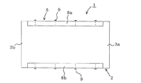
[実施の形態5]
図13は本実施の形態5に係る床支持部材の斜視図、図14は図13の補強部材の斜視図、図15は図13のE−E断面図である。なお、実施の形態1と同じ部分にはこれと同じ符号を付し、説明の一部を省略する。
本実施の形態は、実施の形態1の木製心材2と同じ構造の木製心材2と、上辺にすき間18を設けた中空の角形鋼(以下、上隙角形鋼という)15とによって床支持部材1を構成したものである。
[Embodiment 5]
13 is a perspective view of a floor support member according to
In the present embodiment, the
木製心材2は、実施の形態1の場合と同様に、上下面の両端部側の露出部3a,3bを残して、上隙角形鋼15のフランジ部19a,19bの板厚に対応した深さの挫彫り部4a,4bを設けたものである。
また、補強用の形鋼である上隙角形鋼15は、薄鋼板からなり、木製心材2の挫彫り部4a,4bの長さとほぼ等しい長さで、両側壁の高さが木製心材2の成(せい)ほぼ等しい中空の角形鋼の上辺の幅方向の中央部の長手方向に、スリットによりすき間18を設け、その両側にフランジ部19a,19bを形成したものである。
As in the case of the first embodiment, the
The upper gap
上記のように構成した上隙角形鋼15を木製心材2に取付けるには、フランジ部19a,19bを僅かに外方に開き気味にして、その一端から木製心材2に嵌合し、挫彫り部4a,4b上迄送り込んで、底部16及びフランジ部19a,19bを挫彫り部4a,4b上に位置させる。このとき、フランジ部19a,19bは自身のスプリングバックにより元の状態に戻り、挫彫り部4a内に位置する。
この状態で、上隙角形鋼15のフランジ部19a,19bを、例えば複数のねじ9により木製心材2に留め付けて固定すると共に、底部16も複数のねじ9により木製心材2に固定する。このとき、フランジ部19a,19bの上面、底部16の下面は、木製心材2の露出部3a,3bの上面及び下面とそれぞれ面一(つらいち)になる。
本実施の形態に係る床用支持部材の作用、効果は、実施の形態1〜4の場合とほぼ同様である。
In order to attach the upper gap
In this state, the
The actions and effects of the floor support member according to the present embodiment are substantially the same as those of the first to fourth embodiments.
[実施の形態6]
図16は本発明の実施の形態6に係る床支持部材の木製心材の斜視図である。
実施の形態4,5では、木製心材2の上下面に挫彫り部4a,4bを設け、補強用の溝形鋼11a,11bの対向するフランジ部13aと13a、13bと13bとの間、又は上隙角形鋼15の対向するフランジ部19a,19bの間にすき間を形成した場合を示した。
[Embodiment 6]
FIG. 16 is a perspective view of the wooden core of the floor support member according to
In the fourth and fifth embodiments, the
本実施の形態は、木製心材2の少なくとも上面の幅方向の中央部に、両端部側に設けた露出部3a,3bと面一(つらいち)で、かつ両者に連続するリブ(露出部3c)を残して、その両側に挫彫り部4c,4dを設けたものである。
これにより、溝形鋼11a,11bのフランジ部13a,13a、上隙角形鋼15のフランジ部19a,19bは、木製心材2の挫彫り部4c,4dにそれぞれ係合するので、床支持部材1の上面をより平坦(面一)にすることができる。
In the present embodiment, ribs (exposed
Accordingly, the
[実施の形態7]
図17は本発明の実施の形態7に係る床支持部材の斜視図及び木製心材の斜視図である。なお、実施の形態1〜6と同じ部分にはこれと同じ符号を付し、説明を省略する。
実施の形態1〜6では、木製心材2の両端部側に露出部3a,3bを設け、その間に挫彫り部4a,4bを設けて補強用の形鋼を取付けた場合を示したが、本実施の形態においては、両端部側に設けた露出部3a,3bの間に、さらに第3の露出部3dを設けたものである。
[Embodiment 7]
FIG. 17 is a perspective view of a floor support member and a perspective view of a wooden core material according to Embodiment 7 of the present invention. In addition, the same code | symbol is attached | subjected to the same part as Embodiment 1-6, and description is abbreviate | omitted.
In Embodiment 1-6, although the exposed
すなわち、木製心材2の両端部側に露出部3a,3bを設けると共に、その間にさらに第三の露出部3cを設け、これら露出部3a,3bと第三の露出部3dとの間に、それぞれ挫彫り部4a,4bを形成したものである。なお、図には、第三の露出部3dを両露出部3a,3bの中間部に設けた場合を示したが、これに限定するものではなく、両露出部3a,3bの間であればどこに設けてもよい。
That is, the exposed
そして、この木製心材2の挫彫り部4a,4bに実施の形態1〜5で説明した補強材であるリップ溝形鋼5、溝形鋼11又は上隙角形鋼15(但し、一般に、実施の形態1〜5の場合より長さが短かく、挫彫り部4a,4bの長さに対応した長さのものを使用する)のいずれかをそれぞれ嵌合し、ねじ9等で固定するようにしたものである。
本実施の形態に係る床支持部材1は、両端部側の露出部3a,3bの間にさらに第三の露出部3dを設けたので、この床支持部材1を床支持構造の木製床支持部材に代えて配設し、その第三の露出部3dに実施の形態1〜5又は本実施の形態に係る床支持部材1を接合することができ、それにより、より強固な床支持構造を得ることができる。
And the
In the
上記の各実施の形態においては、木製心材2の上下面に挫彫り部4を設けた場合を示したが、上面又は下面のいずれか一方のみに挫彫り部4を設けて、これに補強用の形鋼を取付けるようにしてもよい。
また、上記の各実施の形態において、実施の形態1,3〜7では、ムク製材からなる木製心材2を用い、実施の形態2では構造用集成材からなる木製心材2を用いた場合を示したが、これらは適宜変更することができ、またこれら以外の木製心材を用いてもよい。
In each of the above-described embodiments, the case where the
In each of the above-described embodiments, the first and third to seventh embodiments use the
さらに、木製心材2に補強用の形鋼を固定するにあたり、実施の形態1,3〜5及び7ではねじ9を用い、実施の形態2ではくぎ10を用いた場合を示したが、これらはその一例を示すもので、状況に応じてねじ9又はくぎ10のいずれを用いてもよい。
また、実施の形態3〜5では、木製心材2の両側壁と、溝形鋼11a,11bのウェブ内壁、及び上隙角形鋼15の側板内壁との間にすき間を設けた場合を示したが、これらウェブ内壁や側板内壁を木製心材2の両側壁に当接してもよい。
また、上記各実施の形態を適宜組合わせて床支持部材1を構成してもよい。
Furthermore, in fixing the shape steel for reinforcement to the
Moreover, although Embodiment 3-5 showed the case where the clearance gap was provided between the both-sides wall of the
Moreover, you may comprise the
次に、本発明に係る床支持部材の実施例について、図4を参照して説明する。なお、本実施例は、実施の形態1に係る床支持部材を対象としたものである。
木製心材2は、長さL1:4.55m、成(せい)h1:23.5cm、幅W1:4cmの米ツガ材を製材したものを用い、その上下面に両側に長さL2:15cmの露出部3a,3bを残して、その間に長さL3(L1−L2×2):4.25m、深さt1:1.6mmの挫彫り部4a,4bを設けた。
また、リップ溝形鋼5は、板厚t2:1.6mmの薄鋼板を曲げ加工して形成したもので、長さL4:4.20m、ウェブ高さh3:23.5cm、フランジ幅W2:5cmのものを使用した。
Next, an embodiment of the floor support member according to the present invention will be described with reference to FIG. The present example is intended for the floor support member according to the first embodiment.
The
The
上記のようなリップ溝形鋼5の開口部を開き気味にして一方の端部から木製心材2を挿入し、その挫彫り部4a,4bにフランジ部7a,7bを嵌合した。ついで、上下のフランジ部7a,7bからそれぞれ一列、30cm以内の間隔で、ねじ部長さ2cm、ねじ山外径4.8mmの頭部に皿部を有するドリリングタッピンねじ15本を木製心材2に螺入して固定し、床支持部材1を構成した。
これにより、木製心材2とほぼ同じ材料(但し、挫彫り部は設けられていない)の従来の木製床支持部材に比べて約2.5倍の強度(曲げ剛性)を有し、その上木製心材2の露出部3a,3bの上下面と、リップ溝形鋼5のフランジ部7a,7bの上下面とが面一(つらいち)の床支持部材1が得られた。
なお、上記の実施例はその一例を示すもので、各部の寸法等は適宜変更しうることは云う迄もない。
With the opening of the
As a result, it has approximately 2.5 times the strength (bending rigidity) of a conventional wooden floor support member made of substantially the same material as the wooden core material 2 (however, no sculpture is provided). The
The above-described embodiment shows an example, and it goes without saying that the dimensions and the like of each part can be appropriately changed.
[実施の形態8]
次に、本発明に係る床支持部材1を用いた床支持構造の一例について説明する。
図18は本発明に係る床支持部材1(図には、実施の形態1に係る床支持部材1を示してあるが、これに限定するものではない)を、周辺の木製床支持部材20に接合金物25を介して接合した状態を示すものである。
床支持部材1は、木製床支持部材20と直交し、かつその上面(露出部3及びリップ溝形鋼5のフランジ部7の上面)を、木製床支持部材20の上面と面一になるように配設され、その端部(露出部3a)を木製床支持部材20の側面に当接し、接合金物25により、ねじ、くぎ等26によって固定し、両者を一体に接合する。ここで、接合金物25は、アングル形状の金物や腰掛け形状の金物等を用いることができる。
[Embodiment 8]
Next, an example of a floor support structure using the
FIG. 18 shows a
The
このように構成した床支持構造の上面に、床の下地として構造用合板又はこれに類する下地材24を貼り付ける。これにより、床支持部材1の端部には露出部3a,3bが設けられているため、木製支持部材20との接合がきわめて容易である。また、床支持部材1は補強用の形鋼で補強されているので、長期にわたってたわみや曲がりを生じることがなく、構造的に安定し、かつ、木製床支持部材20と床支持部材1の上面が面一(つらいち)になっているので、床の不陸等の問題が発生することのない床支持構造を得ることができる。
A structural plywood or a
図19は床支持構造の別の例を示すものである。本例は、木製床支持部材20に、挫彫りにより床支持部材1の端部の露出部3aの形状に対応した仕口部21を設け、この仕口部21に床支持部材1の露出部3aを、その上面を木製支持部材20の上面と面一(つらいち)になるようにして嵌入し、ねじ、くぎ等26を斜め打ちして留め付け、接合したものである。
FIG. 19 shows another example of the floor support structure. In this example, a wooden
図20は床支持構造のさらに別の例を示すもので、本例においては、木製床支持部材20に代えて実施の形態7に係る床支持部材1を用い、その第三の露出部3dの側面に接合金物25を介して床支持部材1の端部を嵌合したものである。本例によれば、床支持構造の強度(剛性)をさらに増すことができる。
FIG. 20 shows still another example of the floor support structure. In this example, the
上記の説明では、本発明に係る床支持部材を床支持構造に用いた場合を示したが、さらに、天井下地の構成にも実施することができる。 In the above description, the case where the floor support member according to the present invention is used in a floor support structure has been shown, but the present invention can also be applied to a ceiling base structure.
1 床支持部材、2 木製心材、3a〜3d 露出部、4a〜4d 挫彫り部、5 リップ溝形鋼、7a,7b,13a,13b,19a,19b フランジ部、9 ねじ、10 くぎ、11 溝形鋼、15 上隙角形鋼、20 木製支持部材、25 接合金具。
DESCRIPTION OF
Claims (3)
The floor support structure characterized by joining the edge part of the floor support member which concerns on Claim 1 or 2 to the surrounding wooden floor support member or a floor support member.
Priority Applications (1)
| Application Number | Priority Date | Filing Date | Title |
|---|---|---|---|
| JP2003390932A JP2005155026A (en) | 2003-11-20 | 2003-11-20 | Floor support member and floor support structure using the same |
Applications Claiming Priority (1)
| Application Number | Priority Date | Filing Date | Title |
|---|---|---|---|
| JP2003390932A JP2005155026A (en) | 2003-11-20 | 2003-11-20 | Floor support member and floor support structure using the same |
Publications (1)
| Publication Number | Publication Date |
|---|---|
| JP2005155026A true JP2005155026A (en) | 2005-06-16 |
Family
ID=34718158
Family Applications (1)
| Application Number | Title | Priority Date | Filing Date |
|---|---|---|---|
| JP2003390932A Withdrawn JP2005155026A (en) | 2003-11-20 | 2003-11-20 | Floor support member and floor support structure using the same |
Country Status (1)
| Country | Link |
|---|---|
| JP (1) | JP2005155026A (en) |
Cited By (4)
| Publication number | Priority date | Publication date | Assignee | Title |
|---|---|---|---|---|
| KR101009033B1 (en) | 2008-07-11 | 2011-01-17 | 재단법인 포항산업과학연구원 | Modular building floor panel system |
| JP2015081430A (en) * | 2013-10-22 | 2015-04-27 | Jfe建材株式会社 | Mounting fitting and structure for mounting corrugated steel plate on wooden beam |
| CN112431315A (en) * | 2020-12-18 | 2021-03-02 | 惠州市民华建材科技有限公司 | High-strength heat-preservation color steel sandwich plate |
| JP2021195842A (en) * | 2020-06-18 | 2021-12-27 | 日鉄エンジニアリング株式会社 | Joint structure of wooden member and steel member, and steel joint element |
-
2003
- 2003-11-20 JP JP2003390932A patent/JP2005155026A/en not_active Withdrawn
Cited By (5)
| Publication number | Priority date | Publication date | Assignee | Title |
|---|---|---|---|---|
| KR101009033B1 (en) | 2008-07-11 | 2011-01-17 | 재단법인 포항산업과학연구원 | Modular building floor panel system |
| JP2015081430A (en) * | 2013-10-22 | 2015-04-27 | Jfe建材株式会社 | Mounting fitting and structure for mounting corrugated steel plate on wooden beam |
| JP2021195842A (en) * | 2020-06-18 | 2021-12-27 | 日鉄エンジニアリング株式会社 | Joint structure of wooden member and steel member, and steel joint element |
| JP7485551B2 (en) | 2020-06-18 | 2024-05-16 | 日鉄エンジニアリング株式会社 | Joint structure between wooden members and steel members and steel joints |
| CN112431315A (en) * | 2020-12-18 | 2021-03-02 | 惠州市民华建材科技有限公司 | High-strength heat-preservation color steel sandwich plate |
Similar Documents
| Publication | Publication Date | Title |
|---|---|---|
| US8484927B2 (en) | Right-angle girder tie | |
| US7124544B2 (en) | Prefabricated multi-purpose support block for use with I-joists | |
| JP5080191B2 (en) | Exterior wall construction structure | |
| US6418682B1 (en) | Non-structural steel studs | |
| JP2005155026A (en) | Floor support member and floor support structure using the same | |
| JP6645193B2 (en) | Horizontal material, structure for mounting surface material using horizontal material, and structure for mounting surface material and frame material using horizontal material | |
| JP4978726B2 (en) | Bracing connection structure, load-bearing wall panel | |
| JP2005155027A (en) | Floor support member and floor support structure using the same | |
| KR200449811Y1 (en) | Fixing bracket | |
| JP3209111U (en) | Vertical frame material and steel house | |
| JP5447116B2 (en) | Steel structure floor panel, steel structure floor panel joint structure and steel structure floor assembly | |
| AU2006326913A1 (en) | Connector | |
| JP4650316B2 (en) | Banded bracing joint structure, load-bearing wall panel | |
| JPH09328831A (en) | Outside thermal insulating execution method and metal fixture | |
| JP2007262660A (en) | Method of mounting bearing wall panel, bearing wall panel, and building structure | |
| JPH11148197A (en) | Panelized metal ceiling structure | |
| JP2021055465A (en) | Horizontal structural plane reinforcing plate and horizontal structural plane reinforcing structure | |
| JPH06136872A (en) | Joist hanger | |
| JP2005213789A (en) | Composite material for building, and floor structure and floor construction method using the same | |
| JPH09217453A (en) | Floor structure | |
| JP7193368B2 (en) | roof panel | |
| CA2280506C (en) | Non-structural steel studs | |
| JP2002013211A (en) | Fixing fitting | |
| JPH11166276A (en) | Bearing wall structure | |
| JPS6236905Y2 (en) |
Legal Events
| Date | Code | Title | Description |
|---|---|---|---|
| A300 | Withdrawal of application because of no request for examination |
Free format text: JAPANESE INTERMEDIATE CODE: A300 Effective date: 20070206 |