JP2005090403A - Lubrication control device for supercharger with electric motor - Google Patents
Lubrication control device for supercharger with electric motor Download PDFInfo
- Publication number
- JP2005090403A JP2005090403A JP2003326642A JP2003326642A JP2005090403A JP 2005090403 A JP2005090403 A JP 2005090403A JP 2003326642 A JP2003326642 A JP 2003326642A JP 2003326642 A JP2003326642 A JP 2003326642A JP 2005090403 A JP2005090403 A JP 2005090403A
- Authority
- JP
- Japan
- Prior art keywords
- lubricating oil
- electric motor
- motor
- supercharger
- amount
- Prior art date
- Legal status (The legal status is an assumption and is not a legal conclusion. Google has not performed a legal analysis and makes no representation as to the accuracy of the status listed.)
- Pending
Links
Images


Classifications
-
- F—MECHANICAL ENGINEERING; LIGHTING; HEATING; WEAPONS; BLASTING
- F02—COMBUSTION ENGINES; HOT-GAS OR COMBUSTION-PRODUCT ENGINE PLANTS
- F02B—INTERNAL-COMBUSTION PISTON ENGINES; COMBUSTION ENGINES IN GENERAL
- F02B39/00—Component parts, details, or accessories relating to, driven charging or scavenging pumps, not provided for in groups F02B33/00 - F02B37/00
- F02B39/005—Cooling of pump drives
-
- F—MECHANICAL ENGINEERING; LIGHTING; HEATING; WEAPONS; BLASTING
- F02—COMBUSTION ENGINES; HOT-GAS OR COMBUSTION-PRODUCT ENGINE PLANTS
- F02B—INTERNAL-COMBUSTION PISTON ENGINES; COMBUSTION ENGINES IN GENERAL
- F02B37/00—Engines characterised by provision of pumps driven at least for part of the time by exhaust
- F02B37/04—Engines with exhaust drive and other drive of pumps, e.g. with exhaust-driven pump and mechanically-driven second pump
- F02B37/10—Engines with exhaust drive and other drive of pumps, e.g. with exhaust-driven pump and mechanically-driven second pump at least one pump being alternatively or simultaneously driven by exhaust and other drive, e.g. by pressurised fluid from a reservoir or an engine-driven pump
-
- F—MECHANICAL ENGINEERING; LIGHTING; HEATING; WEAPONS; BLASTING
- F02—COMBUSTION ENGINES; HOT-GAS OR COMBUSTION-PRODUCT ENGINE PLANTS
- F02B—INTERNAL-COMBUSTION PISTON ENGINES; COMBUSTION ENGINES IN GENERAL
- F02B39/00—Component parts, details, or accessories relating to, driven charging or scavenging pumps, not provided for in groups F02B33/00 - F02B37/00
- F02B39/02—Drives of pumps; Varying pump drive gear ratio
- F02B39/08—Non-mechanical drives, e.g. fluid drives having variable gear ratio
- F02B39/10—Non-mechanical drives, e.g. fluid drives having variable gear ratio electric
-
- F—MECHANICAL ENGINEERING; LIGHTING; HEATING; WEAPONS; BLASTING
- F02—COMBUSTION ENGINES; HOT-GAS OR COMBUSTION-PRODUCT ENGINE PLANTS
- F02B—INTERNAL-COMBUSTION PISTON ENGINES; COMBUSTION ENGINES IN GENERAL
- F02B39/00—Component parts, details, or accessories relating to, driven charging or scavenging pumps, not provided for in groups F02B33/00 - F02B37/00
- F02B39/14—Lubrication of pumps; Safety measures therefor
-
- F—MECHANICAL ENGINEERING; LIGHTING; HEATING; WEAPONS; BLASTING
- F02—COMBUSTION ENGINES; HOT-GAS OR COMBUSTION-PRODUCT ENGINE PLANTS
- F02B—INTERNAL-COMBUSTION PISTON ENGINES; COMBUSTION ENGINES IN GENERAL
- F02B39/00—Component parts, details, or accessories relating to, driven charging or scavenging pumps, not provided for in groups F02B33/00 - F02B37/00
- F02B39/16—Other safety measures for, or other control of, pumps
-
- Y—GENERAL TAGGING OF NEW TECHNOLOGICAL DEVELOPMENTS; GENERAL TAGGING OF CROSS-SECTIONAL TECHNOLOGIES SPANNING OVER SEVERAL SECTIONS OF THE IPC; TECHNICAL SUBJECTS COVERED BY FORMER USPC CROSS-REFERENCE ART COLLECTIONS [XRACs] AND DIGESTS
- Y02—TECHNOLOGIES OR APPLICATIONS FOR MITIGATION OR ADAPTATION AGAINST CLIMATE CHANGE
- Y02T—CLIMATE CHANGE MITIGATION TECHNOLOGIES RELATED TO TRANSPORTATION
- Y02T10/00—Road transport of goods or passengers
- Y02T10/10—Internal combustion engine [ICE] based vehicles
- Y02T10/12—Improving ICE efficiencies
Landscapes
- Engineering & Computer Science (AREA)
- Chemical & Material Sciences (AREA)
- Combustion & Propulsion (AREA)
- Mechanical Engineering (AREA)
- General Engineering & Computer Science (AREA)
- Output Control And Ontrol Of Special Type Engine (AREA)
- Lubrication Of Internal Combustion Engines (AREA)
- Supercharger (AREA)
Abstract
【課題】 本発明の目的は、電動機付過給機に対して、常に最適な量の潤滑油を供給することで、電動機過給機に良好な性能を発揮させることのできる電動機付過給機の潤滑制御装置を提供すること。
【解決手段】 本発明の電動機付過給機の潤滑制御装置は、車両に搭載された内燃機関1の吸気通路3上に配設され、回転式電動機2bによって駆動される過給機2と、電動機2bの回転軸2a近傍に潤滑油を供給する潤滑油供給手段8〜10と、潤滑油供給手段8〜10による潤滑油の供給を制御する制御手段6,7とを備えており、制御手段6,7が、電動機2bの回転駆動時に、該電動機2bの回転数が高いほど回転軸2a近傍への潤滑油の供給量を多くすることを特徴としている。
【選択図】 図1PROBLEM TO BE SOLVED: To provide a supercharger with an electric motor capable of causing the electric motor supercharger to exhibit good performance by always supplying an optimum amount of lubricating oil to the supercharger with an electric motor. Providing a lubrication control device for
A lubrication control device for a supercharger with an electric motor according to the present invention is provided on an intake passage 3 of an internal combustion engine 1 mounted on a vehicle, and is driven by a rotary electric motor 2b. Lubricating oil supply means 8 to 10 for supplying lubricating oil to the vicinity of the rotating shaft 2a of the electric motor 2b, and control means 6 and 7 for controlling the supply of lubricating oil by the lubricating oil supply means 8 to 10 are provided. Nos. 6 and 7 are characterized in that, when the electric motor 2b is driven to rotate, the amount of lubricating oil supplied to the vicinity of the rotary shaft 2a increases as the rotational speed of the electric motor 2b increases.
[Selection] Figure 1
Description
本発明は、吸気通路上に配設された電動機付過給機への潤滑油供給を制御する潤滑制御装置に関する。 The present invention relates to a lubrication control device that controls the supply of lubricating oil to a supercharger with an electric motor disposed on an intake passage.
[特許文献1]に記載されているように、エンジンの吸気通路上に電動機で駆動する過給機を配設し、この過給機による過給によって高出力(あるいは、低燃費)を得ようとする試みは以前から知られている。[特許文献1]に記載されたターボユニットでは、エンジン潤滑油を電動機の周囲に循環させ、潤滑・冷却を行っている。
しかし、[特許文献1]に記載されたターボユニットでは、エンジン潤滑油を利用して電動機の潤滑・冷却を行っているので、エンジン側の潤滑油循環に応じた一定の循環量で潤滑油が循環されるだけである。このため、電動機の駆動状況によっては潤滑油量が適切でない場合も想定される。例えば、高負荷時に電動機を高回転駆動させてターボユニットによる過給効果を最大限に得ようとした場合に、潤滑油量が不足して十分な潤滑・冷却が行われないことなどが懸念される。従って、本発明の目的は、電動機付過給機に対して、常に最適な量の潤滑油を供給することで、電動機過給機に良好な性能を発揮させることのできる電動機付過給機の潤滑制御装置を提供することにある。 However, in the turbo unit described in [Patent Document 1], since the motor is lubricated and cooled using the engine lubricating oil, the lubricating oil is supplied with a constant circulation amount corresponding to the lubricating oil circulation on the engine side. It is only circulated. For this reason, the case where the amount of lubricating oil is not appropriate depending on the driving state of the electric motor is also assumed. For example, there is a concern that when the motor is driven at a high rotation speed under a high load to obtain the maximum turbocharging effect by the turbo unit, the lubricating oil amount is insufficient and sufficient lubrication / cooling is not performed. The Accordingly, an object of the present invention is to provide a supercharger with an electric motor that can cause the electric motor supercharger to exhibit good performance by always supplying an optimal amount of lubricating oil to the supercharger with an electric motor. The object is to provide a lubrication control device.
請求項1に記載の電動機付過給機の潤滑制御装置は、車両に搭載された内燃機関の吸気通路上に配設され、回転式電動機によって駆動される過給機と、電動機の回転軸近傍に潤滑油を供給する潤滑油供給手段と、潤滑油供給手段による潤滑油の供給を制御する制御手段とを備えており、制御手段が、電動機の回転駆動時に、該電動機の回転数が高いほど回転軸近傍への潤滑油の供給量を多くすることを特徴としている。 A lubrication control device for a supercharger with an electric motor according to claim 1 is provided on an intake passage of an internal combustion engine mounted on a vehicle and is driven by a rotary electric motor, and in the vicinity of a rotation shaft of the electric motor And a control means for controlling the supply of the lubricating oil by the lubricating oil supply means, and the control means increases the rotational speed of the motor when the motor is driven to rotate. It is characterized by increasing the amount of lubricating oil supplied to the vicinity of the rotating shaft.
請求項2に記載の発明は、請求項1に記載の電動機付過給機の潤滑制御装置において、制御手段が、電動機の駆動回転数が同一である場合には潤滑油温度が高いほど回転軸近傍への潤滑油の供給量を多くすると共に、電動機の回転数が所定回転数以下の場合には電動機の駆動回転数及び潤滑油温度にかかわらず供給量を所定量以下とすることを特徴としている。 According to a second aspect of the present invention, in the lubrication control device for a supercharger with an electric motor according to the first aspect, when the control means has the same driving rotational speed of the electric motor, the higher the lubricating oil temperature, the higher the rotating shaft. The amount of lubricating oil supplied to the vicinity is increased, and when the rotational speed of the electric motor is equal to or lower than the predetermined rotational speed, the supplied amount is set to the predetermined amount regardless of the driving rotational speed of the electric motor and the lubricating oil temperature. Yes.
請求項1に記載の電動機付過給機の潤滑制御装置によれば、電動機の回転駆動時に、制御手段が電動機の回転数に応じて潤滑油供給量を調節(回転数が高いほど潤滑油供給量を多く)するので、電動機付過給機に対して常に最適な量の潤滑油を供給でき、電動機過給機に良好な性能を発揮させることができる。例えば、電動機の高回転時には、潤滑油供給量を増やして確実な潤滑と十分な冷却とが行われるようにし、低回転時には、潤滑油供給量は潤滑・冷却な量を維持しつつも少な目にして、潤滑油の粘性による電動機回転抵抗増加を抑制して電動機過給機に良好な性能を発揮させる。 According to the lubrication control device for a supercharger with an electric motor according to claim 1, when the motor is driven to rotate, the control means adjusts the amount of lubricating oil supplied according to the number of revolutions of the motor (the higher the number of revolutions, the more lubricant oil is supplied. Therefore, the optimum amount of lubricating oil can always be supplied to the supercharger with electric motor, and the electric motor supercharger can exhibit good performance. For example, when the motor rotates at a high speed, the lubrication oil supply amount is increased so that reliable lubrication and sufficient cooling are performed, and at a low rotation, the lubrication oil supply amount is kept low while maintaining a lubrication / cooling amount. In this way, the motor supercharger exhibits good performance by suppressing the increase in motor rotation resistance due to the viscosity of the lubricating oil.
請求項2に記載の電動機付過給機の潤滑制御装置によれば、電動機の駆動回転数が同一である場合には潤滑油温度が高いほど回転軸近傍への潤滑油の供給量を多くする。電動機の駆動回転数が同一(同等)でも、潤滑油温度が高いほど油膜切れが生じやすい。このため、潤滑油温度が高いほど供給量を増やして油膜切れを防止し、電動機過給機に良好な性能を発揮させる。また、潤滑油量が多いと潤滑油の粘性によって電動機の回転抵抗となり易い。このため、潤滑油温度が低く粘性が大きいときは潤滑油供給量を抑制する(換言すれば、潤滑油温度が高くなって粘性が小さくなるほど潤滑油供給量を増やす)ことで電動機過給機に良好な性能を発揮させる。即ち、ここでは、電動機の回転数に加えて、潤滑油温度も考慮して電動機への潤滑油の供給を制御している。
According to the lubrication control device for a supercharger with an electric motor according to
さらに、電動機の回転数が所定回転数以下となる場合には、潤滑油の粘性の影響を受け易くなる。潤滑油の粘性による電動機回転抵抗増加は、過給機のレスポンスを悪化させることになる(特に、電動機を用いた過給を行う過渡時のレスポンスが悪化する)。このため、電動機の回転数が所定回転数以下となる場合には、電動機の駆動回転数及び潤滑油温度にかかわらず供給量を所定量以下とすることで、潤滑油の粘性による電動機回転抵抗増加を抑制して電動機過給機に良好な性能を発揮させる。 Furthermore, when the rotational speed of the electric motor is equal to or lower than the predetermined rotational speed, it is easily affected by the viscosity of the lubricating oil. An increase in the rotational resistance of the motor due to the viscosity of the lubricating oil deteriorates the response of the supercharger (particularly, the response at the time of transient when supercharging using the motor is performed). For this reason, when the rotational speed of the motor is equal to or lower than the predetermined rotational speed, the motor rotation resistance increases due to the viscosity of the lubricating oil by setting the supply amount below the predetermined amount regardless of the driving rotational speed of the motor and the lubricating oil temperature. This makes the electric motor supercharger perform well.
本発明の制御装置の一実施形態について以下に説明する。本実施形態の制御装置を有するエンジン1を図1に示す。本実施形態で説明するエンジン(内燃機関)1は、多気筒エンジンであるが、ここではそのうちの一気筒のみが断面図として図1に示されている。このエンジン1は、ターボユニット(過給機)2を有している。ターボユニット2は、吸気通路3上に配置されたコンプレッサホイールと排気通路4上に配置されたタービンホイールとが同一回転軸で連結されている(以下、この部分を単にタービン/コンプレッサ2aと言う)。本実施形態のターボユニットには、この回転軸が出力軸となるようにモータ(電動機)2bが内蔵されている。即ち、本実施形態のターボユニット2は電動機付ターボチャージャ(電動機付コンプレッサ)である。
An embodiment of the control device of the present invention will be described below. An engine 1 having a control device of the present embodiment is shown in FIG. An engine (internal combustion engine) 1 described in the present embodiment is a multi-cylinder engine, but only one cylinder is shown in FIG. 1 as a cross-sectional view. The engine 1 has a turbo unit (supercharger) 2. In the
ターボユニット2は、排気流の持つエネルギー(排気エネルギー)によって過給を行う通常の過給機としても機能し得るが、バッテリ5から供給される電気エネルギーによってタービン/コンプレッサ2aを強制的に駆動することでさらなる過給を行うこともできる。また、排気エネルギーを利用して、タービン/コンプレッサ2aを介してモータ2bに回生発電を行わせて電力を回収することもできる。即ち、本実施形態の電動機付ターボチャージャは、発電機付タービンとしても機能し得る。このため、モータ2bは、モータジェネレータ(MG)とも呼ばれることがある。
The
モータ2bは、タービン/コンプレッサ2aの回転軸に固定されたロータと、その周囲に配置されたステータとを主たる構成部分として有している。モータ2bの内部には、タービン/コンプレッサ2aの回転軸部分の潤滑油温度を検出するための温度センサ2cが内蔵されている。本実施形態では、温度センサ2cは高温となる回転軸の排気側に設置したが、吸気側に設置してもよい。温度センサ2cは、モータ2bを有するターボユニット2を制御するコントローラ6に接続されており、コントローラ6によって回転軸部の潤滑油温度が監視されている。
The motor 2b has a rotor fixed to the rotating shaft of the turbine / compressor 2a and a stator disposed around the rotor as main components. Inside the motor 2b, a
また、モータ2bも、上述したコントローラ6に接続されている。このコントローラ6は、エンジン1全体の制御を司る電子制御ユニット(ECU)7に接続されている。コントローラ6はバッテリ5にも接続されており、バッテリ5から電力を供給される。モータ2bは、ECU7及びコントローラ6によって印可電力等が制御されており、これによって回転数制御、即ち、過給圧制御が行われている。なお、モータ2bによって、タービン/コンプレッサ2aの回転数(即ち、モータ2bの回転数・ターボ回転数)を検出することができる。この回転数検出は、モータ2bが駆動されている状態であっても、駆動されていない状態であっても行える。コントローラ6は、モータ2bの駆動を制御するだけでなく、モータ2bが回生発電した電力の電圧変換を行うインバータとしての機能も有している。回生発電による電力は、コントローラ6によって電圧変換された後にバッテリ5に充電されたり、直接エンジン1やその他の電装系機器によって消費される。
The motor 2b is also connected to the controller 6 described above. The controller 6 is connected to an electronic control unit (ECU) 7 that controls the entire engine 1. The controller 6 is also connected to the battery 5 and is supplied with power from the battery 5. In the motor 2b, the applied electric power and the like are controlled by the
ターボユニット2には、そのタービン/コンプレッサ2aの回転軸近傍に潤滑油を循環させるオイル流路8も接続されている。本実施形態のターボユニット2は、循環される潤滑油によって、タービン/コンプレッサ2aの回転軸の潤滑・冷却を行っている。なお、この潤滑油循環は、タービン/コンプレッサ2aの回転軸だけでなくターボユニット2全体を冷却する効果もある。オイル流路8は、ターボユニット2の循環・冷却のための潤滑油を貯留するオイルパン9に接続されている。また、オイル流路8上には、潤滑油をオイルパン9からターボユニット2に向けて送出する電動のポンプ10も配設されている。
The
ポンプ10も、コントローラ6に接続されており、その駆動がコントローラ6によって制御されている。即ち、コントローラ6によってポンプ10の駆動を制御することで、潤滑油の循環量(ターボユニット2への供給量)を制御している。これらの、オイル流路8やオイルパン9、ポンプ10などが、潤滑油供給手段として機能している。また、コントローラ6やECU7などが制御手段として機能している。コントローラ6及びECU7は、CPU,ROM,RAM等からなる電子制御ユニットである。
The
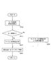
上述した構成の制御装置によってターボユニット(過給機)2への潤滑油量を制御する際のフローチャートを図2に示す。まず、潤滑油量を決定する際のパラメータとなるモータ2bの回転数と潤滑油温を検出する(ステップ200)。上述したように、モータ2bの回転数(タービン/コンプレッサ2a[回転軸]の回転数:ターボ回転数)は、モータ2b自身で検出できる。また、潤滑油温は、温度センサ2cによって、タービン/コンプレッサ2aの排気側回転軸の油温が検出されている。次に、モータ2bによって、過給アシストを行っているか否か判定する(ステップ210)。
FIG. 2 shows a flowchart when the amount of lubricating oil to the turbo unit (supercharger) 2 is controlled by the control device having the above-described configuration. First, the rotational speed of the motor 2b and the lubricating oil temperature, which are parameters for determining the amount of lubricating oil, are detected (step 200). As described above, the rotational speed of the motor 2b (the rotational speed of the turbine / compressor 2a [rotary shaft]: turbo rotational speed) can be detected by the motor 2b itself. The lubricating oil temperature is detected by the
モータ2bによる過給アシストを行っている場合は、ステップ200で検出したモータ2bの回転数及び潤滑油温とに基づいて、図3に示されるマップから潤滑油量を決定する(ステップ220)。図3のマップから分かるように、潤滑油量は、モータ2bの駆動回転数が高いほど多くされている。このようにすることで、モータ2bの高回転時には潤滑油量を増やしてオイル切れなどを抑止して確実な潤滑を実現すると共に、より多くの熱をターボユニット2から持ち去って十分な冷却が行われるようにしている。また、モータ2bの低回転時には潤滑油量を潤滑・冷却に必要な量を維持しつつも少なくして潤滑油の粘性による回転抵抗増加を抑制している。
When supercharging assistance is performed by the motor 2b, the amount of lubricating oil is determined from the map shown in FIG. 3 based on the rotational speed of the motor 2b and the lubricating oil temperature detected in step 200 (step 220). As can be seen from the map in FIG. 3, the amount of lubricating oil is increased as the driving speed of the motor 2 b is higher. In this way, when the motor 2b is rotating at a high speed, the amount of lubricating oil is increased to prevent oil shortage and the like, thereby realizing reliable lubrication and taking away more heat from the
また、図3のマップからは、モータ2bの駆動回転数が同一である場合には、潤滑油温が高いほど潤滑油量を多くしていることも分かる。モータ2bの駆動回転数が一定であったとしても、潤滑油温が高いほど油膜切れが生じやすい。このため、潤滑油温が高いほど潤滑油量を増やして油膜切れを防止している。また、潤滑油量が多いと潤滑油の粘性によってモータ2bの回転抵抗となり易い。このため、潤滑油温が低く粘性が大きいときは潤滑油供給量を抑制して、即ち、潤滑油温が高くなる(粘性が小さくなる)ほど潤滑油量を増やすようにすることで、粘性によるモータ2bの回転増加に起因するターボラグを抑制している。 Further, from the map of FIG. 3, it can be seen that when the driving speed of the motor 2 b is the same, the amount of lubricating oil increases as the lubricating oil temperature increases. Even if the driving speed of the motor 2b is constant, the oil film is more likely to be cut off as the lubricating oil temperature is higher. For this reason, the higher the lubricating oil temperature is, the more the amount of lubricating oil is increased to prevent oil film breakage. Further, if the amount of lubricating oil is large, the rotational resistance of the motor 2b is likely to be caused by the viscosity of the lubricating oil. For this reason, when the lubricating oil temperature is low and the viscosity is large, the lubricating oil supply amount is suppressed, that is, the lubricating oil amount is increased as the lubricating oil temperature becomes higher (viscosity becomes smaller). Turbo lag caused by increased rotation of the motor 2b is suppressed.
さらに、図3のマップからは、モータ2bの回転数が所定回転数以下となる場合には、モータ2bの駆動回転数や潤滑油温にかかわらず潤滑油量は所定量以下(ここでは一定値)とされていることも分かる。モータ2bの回転数が低回転になると潤滑油の粘性の影響を受け易くなる。潤滑油の粘性による回転抵抗増加はターボラグの原因となる。特に、モータ2bによる過給アシストの過渡時のレスポンスが悪化する。このため、モータ2bの回転数がある程度低回転(ここでは所定回転数以下がこれに相当する)となった場合には、モータ2bの駆動回転数や潤滑油温にかかわらず潤滑油量を所定量以下とし、潤滑油の粘性による回転抵抗増加を抑制している。 Further, from the map of FIG. 3, when the rotational speed of the motor 2b is equal to or lower than the predetermined rotational speed, the lubricating oil amount is equal to or smaller than the predetermined amount (here, a constant value) regardless of the driving rotational speed of the motor 2b and the lubricating oil temperature. ). When the rotational speed of the motor 2b is low, it is easily affected by the viscosity of the lubricating oil. An increase in rotational resistance due to the viscosity of the lubricating oil causes turbo lag. In particular, the response at the time of transition of supercharging assistance by the motor 2b is deteriorated. For this reason, when the rotational speed of the motor 2b is low to some extent (here, this is equal to or lower than the predetermined rotational speed), the amount of lubricating oil is set regardless of the driving rotational speed of the motor 2b and the lubricating oil temperature. The rotation resistance increase due to the viscosity of the lubricating oil is suppressed below the fixed amount.
ステップ220で潤滑油量が決定された後は、決定された潤滑油量がターボユニット2に対して供給されるように、コントローラ6やECU7によってポンプ10が制御される(ステップ230)。一方、モータ2bによる過給アシストが行われいない場合、即ち、ステップ210が否定される場合は、図3のマップとは異なるもう一つのマップに基づいて、潤滑油量が決定される(ステップ240)。本実施形態では、この場合もモータ2bの回転数と潤滑油温とに基づいて潤滑油量が決定されるが、その絶対量は、モータ2bによる過給アシストよりも少なくされている。モータ2bが排気エネルギーだけで回転している場合と、電気エネルギーでさらに過給アシストしているときとでは、同一回転数でも後者の場合の潤滑油量を多くしている。
After the lubricant amount is determined in step 220, the
本発明は上述した実施形態に限定されるものではない。例えば、上述した実施形態においては、モータ2b付きのターボユニット2の循環系統とエンジン1の循環系統とを独立させた。しかし、ターボユニット2への循環油量を制御できるのであれば、上述した2つの循環系統を統合しても良い(潤滑油は両系統を循環する)。このような場合、エンジン1側の潤滑油の循環はエンジン出力を用いたメカニカルポンプで行い、ターボユニット2側の潤滑油の循環は循環量の調節の容易なポンプで行うようにしてもよい。また、ターボユニット2側の潤滑油の循環に関しては、モータ2bの駆動中のみ循環量の調節の容易なポンプで行い、モータ2bの非駆動中にはエンジン出力を用いたメカニカルポンプで行うようにしてもよい。
The present invention is not limited to the embodiment described above. For example, in the above-described embodiment, the circulation system of the
あるいは、本実施形態のような電動のポンプ10を用いずに、エンジン出力を用いたメカニカルポンプと流量調節機構を設けて本発明の制御装置を構築することも考えられる。このときの流量調節機構としては、例えば、流量調節用のDUTY比制御可能なバルブを利用することなどが考えられる。また、この場合の潤滑油送出量の上限はエンジン出力変動に左右されてしまうので、これを改善するためにメカニカルポンプで送出された潤滑油を所定の高圧状態で貯留させておくタンクのようなものを設けても良い。さらに、上述した実施形態では、ターボ回転数はモータ2bによって検出した。しかし、ターボ回転数(即ち、モータ2bの回転数)を検出するために、センサを設置し、このセンサによって検出するようにしてもよい。
Alternatively, it is also conceivable to construct the control device of the present invention by providing a mechanical pump using the engine output and a flow rate adjusting mechanism without using the
1…エンジン、2…ターボユニット(過給機)、2a…タービン/コンプレッサ(回転軸)、2b…モータ(電動機)、2c…温度センサ、3…吸気通路、4…排気通路、5…バッテリ、6…コントローラ(制御手段)、7…ECU(制御手段)、8…オイル流路(潤滑油供給手段)、9…オイルパン(潤滑油供給手段)、9…ターボユニット(潤滑油供給手段)、10…ポンプ(潤滑油供給手段)。 DESCRIPTION OF SYMBOLS 1 ... Engine, 2 ... Turbo unit (supercharger), 2a ... Turbine / compressor (rotating shaft), 2b ... Motor (electric motor), 2c ... Temperature sensor, 3 ... Intake passage, 4 ... Exhaust passage, 5 ... Battery, 6 ... Controller (control means), 7 ... ECU (control means), 8 ... Oil flow path (lubricating oil supply means), 9 ... Oil pan (lubricating oil supply means), 9 ... Turbo unit (lubricating oil supply means), 10: Pump (lubricating oil supply means).
Claims (2)
前記電動機の回転軸近傍に潤滑油を供給する潤滑油供給手段と、
前記潤滑油供給手段による潤滑油の供給を制御する制御手段とを備えており、
前記制御手段が、前記電動機の回転駆動時に、該電動機の回転数が高いほど前記回転軸近傍への潤滑油の供給量を多くすることを特徴とする電動機付過給機の潤滑制御装置。 A supercharger disposed on an intake passage of an internal combustion engine mounted on a vehicle and driven by a rotary electric motor;
Lubricating oil supply means for supplying lubricating oil in the vicinity of the rotating shaft of the electric motor;
Control means for controlling the supply of lubricating oil by the lubricating oil supply means,
The lubrication control device for a supercharger with an electric motor, wherein the control means increases the supply amount of lubricating oil to the vicinity of the rotary shaft as the rotational speed of the electric motor increases when the electric motor is driven to rotate.
Priority Applications (1)
| Application Number | Priority Date | Filing Date | Title |
|---|---|---|---|
| JP2003326642A JP2005090403A (en) | 2003-09-18 | 2003-09-18 | Lubrication control device for supercharger with electric motor |
Applications Claiming Priority (1)
| Application Number | Priority Date | Filing Date | Title |
|---|---|---|---|
| JP2003326642A JP2005090403A (en) | 2003-09-18 | 2003-09-18 | Lubrication control device for supercharger with electric motor |
Publications (1)
| Publication Number | Publication Date |
|---|---|
| JP2005090403A true JP2005090403A (en) | 2005-04-07 |
Family
ID=34456763
Family Applications (1)
| Application Number | Title | Priority Date | Filing Date |
|---|---|---|---|
| JP2003326642A Pending JP2005090403A (en) | 2003-09-18 | 2003-09-18 | Lubrication control device for supercharger with electric motor |
Country Status (1)
| Country | Link |
|---|---|
| JP (1) | JP2005090403A (en) |
Cited By (4)
| Publication number | Priority date | Publication date | Assignee | Title |
|---|---|---|---|---|
| WO2008029211A1 (en) * | 2006-09-06 | 2008-03-13 | Toyota Jidosha Kabushiki Kaisha | Electric supercharger |
| JP2008267260A (en) * | 2007-04-19 | 2008-11-06 | Toyota Motor Corp | Turbocharger cooling system |
| JP2014159758A (en) * | 2013-02-19 | 2014-09-04 | Toyota Motor Corp | Hydraulic control device of engine |
| US9470140B2 (en) | 2011-07-15 | 2016-10-18 | Mitsubishi Heavy Industries, Ltd. | Electric supercharger, assembling method of the same, and internal combustion engine |
Citations (7)
| Publication number | Priority date | Publication date | Assignee | Title |
|---|---|---|---|---|
| JPS62185840U (en) * | 1986-05-20 | 1987-11-26 | ||
| JPS63202733U (en) * | 1987-06-18 | 1988-12-27 | ||
| JPH0411227U (en) * | 1990-05-22 | 1992-01-30 | ||
| JPH06159029A (en) * | 1992-11-17 | 1994-06-07 | Mazda Motor Corp | Hydraulic pressure control device of engine |
| JPH06323157A (en) * | 1993-05-13 | 1994-11-22 | Ishikawajima Harima Heavy Ind Co Ltd | Lubricating oil amount adjusting device for turbocharger |
| JP2001527613A (en) * | 1995-09-18 | 2001-12-25 | ターボダイン システムズ インコーポレイテッド | Turbocharger system with integrated assist electric motor and its cooling system |
| JP2002332864A (en) * | 2001-05-02 | 2002-11-22 | Nippon Soken Inc | Turbocharger lubrication system |
-
2003
- 2003-09-18 JP JP2003326642A patent/JP2005090403A/en active Pending
Patent Citations (7)
| Publication number | Priority date | Publication date | Assignee | Title |
|---|---|---|---|---|
| JPS62185840U (en) * | 1986-05-20 | 1987-11-26 | ||
| JPS63202733U (en) * | 1987-06-18 | 1988-12-27 | ||
| JPH0411227U (en) * | 1990-05-22 | 1992-01-30 | ||
| JPH06159029A (en) * | 1992-11-17 | 1994-06-07 | Mazda Motor Corp | Hydraulic pressure control device of engine |
| JPH06323157A (en) * | 1993-05-13 | 1994-11-22 | Ishikawajima Harima Heavy Ind Co Ltd | Lubricating oil amount adjusting device for turbocharger |
| JP2001527613A (en) * | 1995-09-18 | 2001-12-25 | ターボダイン システムズ インコーポレイテッド | Turbocharger system with integrated assist electric motor and its cooling system |
| JP2002332864A (en) * | 2001-05-02 | 2002-11-22 | Nippon Soken Inc | Turbocharger lubrication system |
Cited By (7)
| Publication number | Priority date | Publication date | Assignee | Title |
|---|---|---|---|---|
| WO2008029211A1 (en) * | 2006-09-06 | 2008-03-13 | Toyota Jidosha Kabushiki Kaisha | Electric supercharger |
| DE112007001954T5 (en) | 2006-09-06 | 2009-12-10 | Toyota Jidosha Kabushiki Kaisha, Toyota-shi | Electric charger |
| US8393152B2 (en) | 2006-09-06 | 2013-03-12 | Toyota Jidosha Kabushiki Kaisha | Electric supercharger |
| DE112007001954B4 (en) * | 2006-09-06 | 2015-09-03 | Toyota Jidosha Kabushiki Kaisha | Electric charger |
| JP2008267260A (en) * | 2007-04-19 | 2008-11-06 | Toyota Motor Corp | Turbocharger cooling system |
| US9470140B2 (en) | 2011-07-15 | 2016-10-18 | Mitsubishi Heavy Industries, Ltd. | Electric supercharger, assembling method of the same, and internal combustion engine |
| JP2014159758A (en) * | 2013-02-19 | 2014-09-04 | Toyota Motor Corp | Hydraulic control device of engine |
Similar Documents
| Publication | Publication Date | Title |
|---|---|---|
| JP4161081B2 (en) | Controller-integrated generator motor | |
| US8393152B2 (en) | Electric supercharger | |
| US8307927B2 (en) | Rotating electrical machine control system and vehicle drive system including rotating electrical machine control system | |
| EP2851255B1 (en) | Control device for hybrid vehicle | |
| EP3124765B1 (en) | Cooling control device | |
| JP7010044B2 (en) | Vehicle engine start control device | |
| CN109667655A (en) | Vehicular engine radiator fan and control method | |
| US7759810B2 (en) | System and method for emergency shutdown of an internal combustion engine | |
| JP4959375B2 (en) | Electric supercharger for automobile and control method thereof | |
| US20220154599A1 (en) | Aircraft internal combustion engine | |
| US11498546B2 (en) | Hybrid vehicle and method of cooling turbocharger | |
| JP2016079935A (en) | Cooling control device for internal combustion engine | |
| JP2007224887A (en) | Hydraulic system | |
| US6800953B2 (en) | Engine starting apparatus and method for controlling the same | |
| JP2005090403A (en) | Lubrication control device for supercharger with electric motor | |
| JP2013237426A (en) | Hybrid vehicle control device | |
| JP2010095017A (en) | Hybrid vehicle and control method of the same | |
| JP4196834B2 (en) | Pump device, automatic transmission and automobile | |
| JP2008282699A (en) | Cooling device of battery | |
| JP4574455B2 (en) | Vehicle drive motor cooling system and control method for vehicle drive motor cooling system | |
| EP4477484A1 (en) | A braking arrangement, a vehicle comprising such a braking arrangement, and a method of controlling the braking arrangement | |
| JP2009281194A (en) | Internal combustion engine with turbocharger | |
| CN118815580A (en) | A control method for electric drive fan of heavy-duty special vehicle | |
| JP2006217758A (en) | Control device for generator with one-way clutch mounted on vehicle | |
| JP2005083318A (en) | Control device for internal combustion engine |
Legal Events
| Date | Code | Title | Description |
|---|---|---|---|
| A621 | Written request for application examination |
Free format text: JAPANESE INTERMEDIATE CODE: A621 Effective date: 20060609 |
|
| A131 | Notification of reasons for refusal |
Free format text: JAPANESE INTERMEDIATE CODE: A131 Effective date: 20090609 |
|
| A02 | Decision of refusal |
Free format text: JAPANESE INTERMEDIATE CODE: A02 Effective date: 20091104 |