JP2005045984A - Rotor for permanent magnet synchronous motor - Google Patents
Rotor for permanent magnet synchronous motor Download PDFInfo
- Publication number
- JP2005045984A JP2005045984A JP2003280307A JP2003280307A JP2005045984A JP 2005045984 A JP2005045984 A JP 2005045984A JP 2003280307 A JP2003280307 A JP 2003280307A JP 2003280307 A JP2003280307 A JP 2003280307A JP 2005045984 A JP2005045984 A JP 2005045984A
- Authority
- JP
- Japan
- Prior art keywords
- magnet
- rotor
- magnets
- pole
- permanent magnet
- Prior art date
- Legal status (The legal status is an assumption and is not a legal conclusion. Google has not performed a legal analysis and makes no representation as to the accuracy of the status listed.)
- Pending
Links
Images


Landscapes
- Permanent Magnet Type Synchronous Machine (AREA)
- Permanent Field Magnets Of Synchronous Machinery (AREA)
Abstract
Description
本発明は,いわゆる永久磁石型同期電動機に関し,特にその回転子の構造に関するものである。 The present invention relates to a so-called permanent magnet type synchronous motor, and more particularly to the structure of the rotor.
従来の技術として、永久磁石型同期電動機の回転子の磁石配列には図2のようなものがある。図2はラジアル配向の磁石配列の一例を示している。
図において、回転子20は回転軸21の周囲に回転子鉄心22とその周囲に永久磁石23を偶数個(図では6個の場合を示している。)、磁極の向きを交互に逆にして周方向表面に配列して成るものである。
この構成によると、製造が簡単でコストダウンになるものの、高い磁束密度が得られにくく、したがってモータの高トルク化にあまり有効ではなかった。
As a conventional technique, there is a magnet arrangement of a rotor of a permanent magnet type synchronous motor as shown in FIG. FIG. 2 shows an example of a radially oriented magnet arrangement.
In the figure, the rotor 20 has an even number of
According to this configuration, although the manufacturing is simple and the cost is reduced, it is difficult to obtain a high magnetic flux density. Therefore, it is not very effective for increasing the torque of the motor.
これに対して、このラジアル配向の磁石配列の欠点を解決するものとして、いわゆるHalbach(ハルバッハ)磁石配列が提案されている(例えば、非特許文献1、特許文献1〜3参照)。 On the other hand, so-called Halbach magnet arrangements have been proposed as solutions to the drawbacks of this radially oriented magnet arrangement (see, for example, Non-Patent Document 1 and Patent Documents 1 to 3).
図3は、上記非特許文献1記載のHalbach磁石配列と同じような同期電動機の回転子の1例の横断面図である。
図3において、30は回転子、31は回転軸、32は回転子鉄心である。33は1極分の磁極で、ここでは主磁石(永久磁石)34と3個の補磁石(永久磁石)34’で1極を成している。したがって、ここでは磁極数が6極、1極の分割数が4個の場合のHalbach磁石配列となっている。各永久磁石34の中に描かれている矢印35、35’は各永久磁石の磁化方向を示している。35は磁化方向が垂直方向を向く主磁石の磁化方向、35’は磁化方向が垂直以外の方向を向く補磁石の磁化方向を示している。
このように、Halbach磁石配列は1極当り複数個の永久磁石に分割し、各永久磁石の磁化方向35’を少しずつ変えることにより、磁極中心に磁束が集中するように各永久磁石を配列しているので、高い磁束密度が得られ、モータの高トルク化などに極めて有効である。分割数は、通常1極当り2〜5分割が用いられる。
FIG. 3 is a cross-sectional view of an example of a rotor of a synchronous motor similar to the Halbach magnet arrangement described in Non-Patent Document 1.
In FIG. 3, 30 is a rotor, 31 is a rotating shaft, and 32 is a rotor core.
In this way, the Halbach magnet arrangement is divided into a plurality of permanent magnets per pole, and the permanent magnets are arranged so that the magnetic flux is concentrated at the center of the magnetic pole by changing the magnetization direction 35 'of each permanent magnet little by little. Therefore, a high magnetic flux density can be obtained, which is extremely effective for increasing the torque of the motor. Usually, 2 to 5 divisions are used per pole.
図4は図3のHalbach磁石配列回転子を用いた同期電動機の一例を示す横断面図である。図において30はHalbach磁石配列回転子で、31は回転軸、32は回転子鉄心、33は永久磁石、また40は固定子で、41は固定子鉄心、41aはティース、42は固定子巻線である。固定子鉄心42は珪素鋼板などの薄板材を多数枚積層して形成し、固定子40の内側は放射状のティース42aとなっており、そのティース42aにそれぞれ絶縁被覆電線42が巻装されている。固定子40の中央空間内に、表面に永久磁石34がHalbach磁石配列された図3の回転子30が配置されている。そこで固定子巻線32に三相交流電流を流すことにより回転磁界が発生し、回転子30を回転させている。
このようなHalbach磁石配列を持つ同期電動機の回転子30は、ラジアル配向の磁石配列と比較して、高い磁束密度が得られ、モータの高トルク化に極めて有効である。
4 is a cross-sectional view showing an example of a synchronous motor using the Halbach magnet array rotor of FIG. In the figure, 30 is a Halbach magnet array rotor, 31 is a rotating shaft, 32 is a rotor core, 33 is a permanent magnet, 40 is a stator, 41 is a stator core, 41a is a tooth, and 42 is a stator winding. It is. The
The
図5は、同じくHalbach磁石配列の1例を示すもので、ここでは磁極数が8極、1極の分割数が1個の場合の例を示している。
図において、50は回転子、51は回転軸、52は回転子鉄心である。53は1極分の磁極で、ここでは1個の主磁石(永久磁石)54と1個の補磁石(永久磁石)54’で1極を成している。各磁石54、54’の中に描かれている矢印55、55’はそれぞれ各磁石54、54’の磁化方向を示している。
この場合、主磁石54の厚みH1と補磁石54’の厚みH2は互いに等しく設定され(H1=H2)、また主磁石541と補磁石54’は互いに隙間なく配置されている。これは図3に示したHalbach磁石配列の回転子についても全く同様のことが言える。
FIG. 5 also shows an example of the Halbach magnet arrangement. Here, an example in which the number of magnetic poles is 8 poles and the number of divisions of 1 pole is 1 is shown.
In the figure, 50 is a rotor, 51 is a rotating shaft, and 52 is a rotor core. 53 is a magnetic pole for one pole, and here, one main magnet (permanent magnet) 54 and one auxiliary magnet (permanent magnet) 54 'form one pole.
In this case, the thickness H1 of the
ところが、従来のHalbach磁石配列を用いた回転子は、複数の磁石を貼り付けるために、貼り付け作業のばらつき、磁石の厚みまたは幅の形状誤差等により、主磁石と補磁石との間に段差が生じ、磁石表面で凹凸が生じ易いという問題があった。
磁石貼り付け時に生じた段差は、磁石表面上の磁束分布に歪を生じさせるため、モータ特性に悪影響を与えるという問題がある。
このため磁石表面の段差をなくし、磁束密度の歪が生じないよう、磁石貼り付け後に切削を行わなければならないという問題があった。
本発明はこのような問題点に鑑みてなされたものであり、磁石貼り付け後の切削工程を省き、良好な磁束密度分布を得ることのできるHalbach磁石配列を用いた永久磁石型同期電動機を提供することを目的とする。
However, in the rotor using the conventional Halbach magnet arrangement, since a plurality of magnets are pasted, there is a step between the main magnet and the auxiliary magnet due to variation in pasting work, shape error in the thickness or width of the magnet, and the like. There was a problem that unevenness was likely to occur on the magnet surface.
Since the step generated when the magnet is attached causes distortion in the magnetic flux distribution on the magnet surface, there is a problem in that the motor characteristics are adversely affected.
For this reason, there has been a problem that it is necessary to perform cutting after attaching the magnet so as to eliminate the step on the surface of the magnet and prevent distortion of the magnetic flux density.
The present invention has been made in view of such problems, and provides a permanent magnet type synchronous motor using a Halbach magnet arrangement that can obtain a good magnetic flux density distribution by omitting the cutting process after magnet attachment. The purpose is to do.
上記問題を解決するため、請求項1記載の発明は、回転軸と,回転子鉄心と,前記回転子鉄心の外周面に固定された複数極の磁極を持ち,前記磁極は1極当り複数個の永久磁石に分割されていて,各永久磁石の磁化方向が磁極中心に集中するように配置された磁石配列,いわゆるHalbach磁石配列を備えた永久磁石型同期電動機の回転子において,1極を構成するHalbach磁石配列の中心に配置される磁石を主磁石、他を補磁石とし、主磁石の厚みをH1、補磁石の厚みをH2としたときに、H1>H2としたことを特徴とするものである。
このように補磁石の厚みを主磁石の厚みよりもあらかじめ小さく設定したため、磁石貼り付け時の段差を吸収できるので、回転子製造時の後切削工程を省くことができる。
請求項2記載の永久磁石型同期電動機の発明は、中央部を空けて放射状に延びるティースを内包する環状の固定子鉄心および該ティースに巻装された巻線とから成る固定子と、前記ティースの先端に形成された中央空間に配備される請求項1記載の回転子と、から成ることを特徴とする。
このように補磁石の厚みを主磁石の厚みよりも小さくした回転子を用いるので切削工程を省くことができるため、磁石組み立て後に加工することなく高性能な同期電動機を提供することができる。
In order to solve the above problem, the invention described in claim 1 has a rotating shaft, a rotor iron core, and a plurality of magnetic poles fixed to the outer peripheral surface of the rotor iron core. A permanent magnet type synchronous motor rotor having a magnet array arranged so that the magnetization direction of each permanent magnet is concentrated at the center of the magnetic pole, that is, a so-called Halbach magnet array, constitutes one pole. The magnet arranged at the center of the Halbach magnet arrangement is a main magnet, the other is a supplementary magnet, the thickness of the main magnet is H1, and the thickness of the supplementary magnet is H2. It is.
As described above, since the thickness of the auxiliary magnet is set to be smaller than the thickness of the main magnet in advance, a step at the time of magnet attachment can be absorbed, so that a post-cutting process at the time of manufacturing the rotor can be omitted.
The invention of a permanent magnet type synchronous motor according to claim 2 comprises: a stator comprising an annular stator core including a tooth extending radially from a central portion; and a winding wound around the tooth; The rotor according to claim 1, which is disposed in a central space formed at the tip of the rotor.
In this way, since the rotor having a thickness of the auxiliary magnet smaller than that of the main magnet is used, the cutting process can be omitted, and therefore a high-performance synchronous motor can be provided without processing after magnet assembly.
以上述べたように、本発明によれば、回転軸と,回転子鉄心と,前記回転子鉄心の外周面に固定された複数極の磁極を持ち,前記磁極は1極当り複数個の永久磁石に分割されていて,各永久磁石の磁化方向が磁極中心に集中するように配置された磁石配列,いわゆるHalbach磁石配列を備えた永久磁石型同期電動機の回転子において、1極を構成するHalbach磁石配列の中心に配置される磁石を主磁石、他を補磁石としたとき、補磁石の厚みを主磁石の厚みよりも小さく設定したことにより、磁石貼り付け時の段差を吸収できるため、後切削工程を省くことができるという効果がある。
また、磁石表面における磁束分布の歪みを抑えることができるため、高性能な永久磁石型同期電動機を提供することができる。
As described above, according to the present invention, a rotating shaft, a rotor core, and a plurality of magnetic poles fixed to the outer peripheral surface of the rotor core are provided, and the magnetic poles have a plurality of permanent magnets per pole. In a permanent magnet type synchronous motor rotor provided with a magnet array arranged so that the magnetization direction of each permanent magnet is concentrated at the center of the magnetic pole, that is, a so-called Halbach magnet array, a Halbach magnet constituting one pole When the magnet arranged at the center of the array is the main magnet and the other is the auxiliary magnet, the thickness of the auxiliary magnet is set to be smaller than the thickness of the main magnet, so that the step when the magnet is attached can be absorbed. There is an effect that the process can be omitted.
Moreover, since the distortion of the magnetic flux distribution on the magnet surface can be suppressed, a high-performance permanent magnet type synchronous motor can be provided.
以下、本発明について、図面に基づいて詳細に説明する。
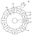
図1は、本発明に係る回転子の断面図である。
図において、10は本発明に係る回転子、11は回転軸、12は回転子鉄心である。13は1極分の磁極で、ここでは1個の主磁石(永久磁石)14と1個の補磁石(永久磁石)14’で1極を成している。各磁石14、14’の中に描かれている矢印15、15’はそれぞれ各磁石14、14’の磁化方向を示している。主磁石15および補磁石15’は回転軸11上に接着などにより貼り付けられている。4は磁石の磁化方向を示しており、いわゆるHalbach磁石配列構造となっている。そして、補磁石15’の厚みH2は主磁石15の厚みH1よりも小さくしている(H1>H2)。
補磁石の厚みH2および主磁石の厚みH1は、磁石表面における磁束密度分布が正弦波になるよう設定する。また、補磁石の厚みH2の決定は有限要素法による解析結果などから求めることができる。
このように補磁石15’の厚みH2を主磁石15の厚みH1よりもあらかじめ小さく設定することにより、磁石貼り付け時の段差を吸収できるため、後切削工程を省くことができる。
Hereinafter, the present invention will be described in detail with reference to the drawings.
FIG. 1 is a cross-sectional view of a rotor according to the present invention.
In the figure, 10 is a rotor according to the present invention, 11 is a rotating shaft, and 12 is a rotor core.
The thickness H2 of the auxiliary magnet and the thickness H1 of the main magnet are set so that the magnetic flux density distribution on the magnet surface is a sine wave. Further, the thickness H2 of the auxiliary magnet can be determined from an analysis result by a finite element method or the like.
Thus, by setting the thickness H2 of the
10 本発明に係る回転子
11 回転軸
12 回転子鉄心
13 1極分の磁極
14 主磁石
14’ 補磁石
15,15’磁石の磁化方向
H1 主磁石の厚み
H2 補磁石の厚み
DESCRIPTION OF
Claims (2)
1極を構成するHalbach磁石配列の中心に配置される磁石を主磁石、他を補磁石とし、主磁石の厚みをH1、補磁石の厚みをH2としたときに、
H1>H2
としたことを特徴とする永久磁石型同期電動機の回転子。 A rotating shaft, a rotor core, and a plurality of magnetic poles fixed to the outer peripheral surface of the rotor core, the magnetic poles being divided into a plurality of permanent magnets per pole, and the magnetization direction of each permanent magnet In a rotor of a permanent magnet type synchronous motor having a magnet arrangement arranged so as to concentrate on the magnetic pole center, so-called Halbach magnet arrangement,
When the magnet arranged at the center of the Halbach magnet array constituting one pole is the main magnet, the other is the auxiliary magnet, the thickness of the main magnet is H1, and the thickness of the auxiliary magnet is H2,
H1> H2
A rotor of a permanent magnet type synchronous motor characterized by the above.
前記ティースの先端に形成された中央空間に配備される請求項1記載の回転子と、から成ることを特徴とする永久磁石型同期電動機。 A stator consisting of an annular stator core containing radially extending teeth spaced apart from the center, and windings wound around the teeth;
A permanent magnet type synchronous motor comprising: the rotor according to claim 1 disposed in a central space formed at a tip of the teeth.
Priority Applications (1)
| Application Number | Priority Date | Filing Date | Title |
|---|---|---|---|
| JP2003280307A JP2005045984A (en) | 2003-07-25 | 2003-07-25 | Rotor for permanent magnet synchronous motor |
Applications Claiming Priority (1)
| Application Number | Priority Date | Filing Date | Title |
|---|---|---|---|
| JP2003280307A JP2005045984A (en) | 2003-07-25 | 2003-07-25 | Rotor for permanent magnet synchronous motor |
Publications (1)
| Publication Number | Publication Date |
|---|---|
| JP2005045984A true JP2005045984A (en) | 2005-02-17 |
Family
ID=34266168
Family Applications (1)
| Application Number | Title | Priority Date | Filing Date |
|---|---|---|---|
| JP2003280307A Pending JP2005045984A (en) | 2003-07-25 | 2003-07-25 | Rotor for permanent magnet synchronous motor |
Country Status (1)
| Country | Link |
|---|---|
| JP (1) | JP2005045984A (en) |
Cited By (27)
| Publication number | Priority date | Publication date | Assignee | Title |
|---|---|---|---|---|
| JP2007019127A (en) * | 2005-07-06 | 2007-01-25 | Yaskawa Electric Corp | Periodic magnetic field generator and linear motor using the same |
| JP2007060818A (en) * | 2005-08-25 | 2007-03-08 | Toyama Univ | Magnetic repulsion support rotating machine |
| JP2007110822A (en) * | 2005-10-13 | 2007-04-26 | Yaskawa Electric Corp | Periodic magnetic field generator, manufacturing method therefor, and linear motor using this periodic magnetic field generator |
| JP2007215292A (en) * | 2006-02-08 | 2007-08-23 | Honda Motor Co Ltd | Method and device for manufacturing rotor of motor |
| JP2007228656A (en) * | 2006-02-21 | 2007-09-06 | Railway Technical Res Inst | Rotating electric machine using the principle of induction repulsive suction |
| JP2007312449A (en) * | 2006-05-16 | 2007-11-29 | Yaskawa Electric Corp | Periodic magnetic field generator and motor employing the same |
| DE102007031745A1 (en) | 2007-07-06 | 2009-01-15 | Max Baermann Gmbh | Magnetic system for producing two-pole homogeneous magnetic field in inner space, has additional magnets for producing additional magnetic fields, where one field causes change of magnetic field in form of convex and/or concave deformation |
| CN101834476A (en) * | 2010-01-05 | 2010-09-15 | 陆美娟 | Permanent magnet generator inner rotor using Halback magnetic array |
| KR101002957B1 (en) * | 2008-02-02 | 2010-12-21 | 종샨 브로드-오션 모터 컴퍼니 리미티드 | Electric motor rotor |
| JP2011239650A (en) * | 2010-05-13 | 2011-11-24 | Masashi Nishimura | Rotator embedded with permanent magnet |
| CN103166406A (en) * | 2011-12-09 | 2013-06-19 | 同济大学 | Permanent Magnet Synchronous Motor with High Power Density and High Efficiency for Vehicles |
| US8487610B2 (en) | 2009-05-07 | 2013-07-16 | Pii Limited | Magnetising assembly |
| US20140084731A1 (en) * | 2011-07-08 | 2014-03-27 | Mitsubishi Electric Corporation | Permanent magnet type electric rotating machine and manufacturing method thereof |
| CN103891103A (en) * | 2011-10-31 | 2014-06-25 | 三菱电机株式会社 | Interior permanent magnet embedded motor and compressor |
| CN104321952A (en) * | 2012-05-22 | 2015-01-28 | 三菱电机株式会社 | Embedded permanent magnet type rotary electric machine |
| CN105811617A (en) * | 2016-04-27 | 2016-07-27 | 霍勇贤 | Coreless outer rotor with magnetism gathering effect for permanent magnet motor and manufacturing method thereof |
| WO2020191345A1 (en) * | 2019-03-21 | 2020-09-24 | Baker Hughes Oilfield Operations Llc | Permanent magnet motor for electrical submersible pump |
| WO2020195006A1 (en) * | 2019-03-28 | 2020-10-01 | 日本電産株式会社 | Rotor and motor |
| EP3761486A1 (en) | 2019-07-05 | 2021-01-06 | Siemens Aktiengesellschaft | Electric rotating machine with permanent magnets |
| KR102234182B1 (en) * | 2019-11-15 | 2021-03-31 | 하이윈 마이크로시스템 코포레이션 | Rotor structure of permanent magnet motor |
| CN112671135A (en) * | 2020-12-25 | 2021-04-16 | 合肥工业大学 | Method for optimizing four-section Halbach array surface-mounted permanent magnet motor |
| WO2021178466A1 (en) * | 2020-03-02 | 2021-09-10 | Falcon Power, LLC | Variable torque generation electric machine employing tunable halbach magnet array |
| JP2021175284A (en) * | 2020-04-27 | 2021-11-01 | 健吾 大倉 | Motor device |
| CN114011571A (en) * | 2021-11-03 | 2022-02-08 | 东北大学 | Vortex separation device for separating different non-magnetic metals |
| FR3123519A1 (en) * | 2021-05-28 | 2022-12-02 | Valeo Equipements Electriques Moteur | ELECTRIC ROTATING MACHINE WITH CO-AXIAL CONFIGURATION |
| US12003146B2 (en) | 2020-03-02 | 2024-06-04 | Falcon Power, LLC | Cascade MosFet design for variable torque generator/motor gear switching |
| DE102011118064B4 (en) * | 2010-11-11 | 2024-12-24 | Denso Corporation | RUNNER AND MOTOR |
-
2003
- 2003-07-25 JP JP2003280307A patent/JP2005045984A/en active Pending
Cited By (41)
| Publication number | Priority date | Publication date | Assignee | Title |
|---|---|---|---|---|
| JP2007019127A (en) * | 2005-07-06 | 2007-01-25 | Yaskawa Electric Corp | Periodic magnetic field generator and linear motor using the same |
| JP2007060818A (en) * | 2005-08-25 | 2007-03-08 | Toyama Univ | Magnetic repulsion support rotating machine |
| JP2007110822A (en) * | 2005-10-13 | 2007-04-26 | Yaskawa Electric Corp | Periodic magnetic field generator, manufacturing method therefor, and linear motor using this periodic magnetic field generator |
| JP2007215292A (en) * | 2006-02-08 | 2007-08-23 | Honda Motor Co Ltd | Method and device for manufacturing rotor of motor |
| JP4728139B2 (en) * | 2006-02-21 | 2011-07-20 | 公益財団法人鉄道総合技術研究所 | Rotating electric machine using the principle of induction repulsive suction |
| JP2007228656A (en) * | 2006-02-21 | 2007-09-06 | Railway Technical Res Inst | Rotating electric machine using the principle of induction repulsive suction |
| JP2007312449A (en) * | 2006-05-16 | 2007-11-29 | Yaskawa Electric Corp | Periodic magnetic field generator and motor employing the same |
| DE102007031745A1 (en) | 2007-07-06 | 2009-01-15 | Max Baermann Gmbh | Magnetic system for producing two-pole homogeneous magnetic field in inner space, has additional magnets for producing additional magnetic fields, where one field causes change of magnetic field in form of convex and/or concave deformation |
| DE102007031745B4 (en) * | 2007-07-06 | 2013-04-25 | Max Baermann Gmbh | Magnetic system for generating homogeneous magnetic fields |
| KR101002957B1 (en) * | 2008-02-02 | 2010-12-21 | 종샨 브로드-오션 모터 컴퍼니 리미티드 | Electric motor rotor |
| US8487610B2 (en) | 2009-05-07 | 2013-07-16 | Pii Limited | Magnetising assembly |
| GB2470054B (en) * | 2009-05-07 | 2013-08-07 | Pii Ltd | Magnetising assembly |
| CN101834476A (en) * | 2010-01-05 | 2010-09-15 | 陆美娟 | Permanent magnet generator inner rotor using Halback magnetic array |
| JP2011239650A (en) * | 2010-05-13 | 2011-11-24 | Masashi Nishimura | Rotator embedded with permanent magnet |
| US9362790B2 (en) | 2010-05-13 | 2016-06-07 | Hiroyuki Nishimura | Permanent magnet embedded rotor |
| DE102011118064B4 (en) * | 2010-11-11 | 2024-12-24 | Denso Corporation | RUNNER AND MOTOR |
| US20140084731A1 (en) * | 2011-07-08 | 2014-03-27 | Mitsubishi Electric Corporation | Permanent magnet type electric rotating machine and manufacturing method thereof |
| US9893571B2 (en) | 2011-07-08 | 2018-02-13 | Mitsubishi Electric Corporation | Permanent magnet type electric rotating machine having main magnets and auxiliary magnets, and manufacturing method thereof |
| CN103891103B (en) * | 2011-10-31 | 2016-11-16 | 三菱电机株式会社 | Permanent magnet embedded type motor and compressor |
| CN103891103A (en) * | 2011-10-31 | 2014-06-25 | 三菱电机株式会社 | Interior permanent magnet embedded motor and compressor |
| CN103166406A (en) * | 2011-12-09 | 2013-06-19 | 同济大学 | Permanent Magnet Synchronous Motor with High Power Density and High Efficiency for Vehicles |
| CN104321952A (en) * | 2012-05-22 | 2015-01-28 | 三菱电机株式会社 | Embedded permanent magnet type rotary electric machine |
| US9735631B2 (en) | 2012-05-22 | 2017-08-15 | Mitsubishi Electric Corporation | Embedded permanent magnet rotary electric machine |
| CN105811617A (en) * | 2016-04-27 | 2016-07-27 | 霍勇贤 | Coreless outer rotor with magnetism gathering effect for permanent magnet motor and manufacturing method thereof |
| EP3942153A4 (en) * | 2019-03-21 | 2022-12-14 | Baker Hughes Oilfield Operations LLC | Permanent magnet motor for electrical submersible pump |
| WO2020191345A1 (en) * | 2019-03-21 | 2020-09-24 | Baker Hughes Oilfield Operations Llc | Permanent magnet motor for electrical submersible pump |
| WO2020195006A1 (en) * | 2019-03-28 | 2020-10-01 | 日本電産株式会社 | Rotor and motor |
| US11916440B2 (en) | 2019-03-28 | 2024-02-27 | Nidec Corporation | Rotor and motor |
| CN113632350A (en) * | 2019-03-28 | 2021-11-09 | 日本电产株式会社 | Rotor and motor |
| CN113632350B (en) * | 2019-03-28 | 2024-05-24 | 日本电产株式会社 | Rotor and motor |
| EP3761486A1 (en) | 2019-07-05 | 2021-01-06 | Siemens Aktiengesellschaft | Electric rotating machine with permanent magnets |
| WO2021004690A1 (en) | 2019-07-05 | 2021-01-14 | Siemens Aktiengesellschaft | Electric rotating machine having permanent magnets |
| KR102234182B1 (en) * | 2019-11-15 | 2021-03-31 | 하이윈 마이크로시스템 코포레이션 | Rotor structure of permanent magnet motor |
| WO2021178466A1 (en) * | 2020-03-02 | 2021-09-10 | Falcon Power, LLC | Variable torque generation electric machine employing tunable halbach magnet array |
| US12003146B2 (en) | 2020-03-02 | 2024-06-04 | Falcon Power, LLC | Cascade MosFet design for variable torque generator/motor gear switching |
| US11532971B2 (en) | 2020-03-02 | 2022-12-20 | Falcon Power, LLC | Variable torque generation electric machine employing tunable Halbach magnet array |
| US11750070B2 (en) | 2020-03-02 | 2023-09-05 | Falcon Power, LLC | Variable torque generation electric machine employing tunable Halbach magnet array |
| JP2021175284A (en) * | 2020-04-27 | 2021-11-01 | 健吾 大倉 | Motor device |
| CN112671135A (en) * | 2020-12-25 | 2021-04-16 | 合肥工业大学 | Method for optimizing four-section Halbach array surface-mounted permanent magnet motor |
| FR3123519A1 (en) * | 2021-05-28 | 2022-12-02 | Valeo Equipements Electriques Moteur | ELECTRIC ROTATING MACHINE WITH CO-AXIAL CONFIGURATION |
| CN114011571A (en) * | 2021-11-03 | 2022-02-08 | 东北大学 | Vortex separation device for separating different non-magnetic metals |
Similar Documents
| Publication | Publication Date | Title |
|---|---|---|
| JP2005045984A (en) | Rotor for permanent magnet synchronous motor | |
| JP5478136B2 (en) | Permanent magnet synchronous motor | |
| JP5414887B2 (en) | Permanent magnet synchronous motor | |
| JP2005304292A (en) | Process for manufacturing rotor unit for motor, rotor unit for motor, and motor | |
| JP2009072010A (en) | Axial gap type coreless rotating machine | |
| JP2005143276A (en) | Axial gap rotating electric machine | |
| CN110268610A (en) | Synchronous Motors with Magnetic Rotating Field Reduction and Flux Concentration | |
| WO2015102106A1 (en) | Motor core and motor | |
| JP4687687B2 (en) | Axial gap type rotating electric machine and field element | |
| JP2018082600A (en) | Double rotor type rotating electrical machine | |
| EP0923804B1 (en) | Method for manufacturing a dc motor and method for forming a permanent magnet for use in a dc motor | |
| JP2009219312A (en) | Rotating electric machine and spindle unit using same | |
| JP2018182118A (en) | Magnetizing device and magnetizing method | |
| JP2005151785A (en) | Synchronous generator having annular armature coil | |
| JP2006271057A (en) | Rotor of permanent magnet synchronous motor | |
| JP2004072820A (en) | Magnetizing jig for rotor of ac motor, and manufacturing method using it | |
| JP2005045881A (en) | Rotary electric machine | |
| JP5433828B2 (en) | Rotating machine | |
| CN111030402B (en) | Directional silicon steel sheet axial magnetic field motor | |
| US11632022B1 (en) | Brushed direct-current slip ring motor | |
| JP2008187863A (en) | Axial gap type rotating electric machine and compressor | |
| JP2008219993A (en) | Axial gap type rotating electric machine and compressor | |
| JPH11299150A (en) | Permanent-magnet motor | |
| JP5353804B2 (en) | Axial gap type rotating electrical machine and manufacturing method thereof | |
| JPH11332147A (en) | Permanent magnet type rotating machine |
Legal Events
| Date | Code | Title | Description |
|---|---|---|---|
| RD04 | Notification of resignation of power of attorney |
Free format text: JAPANESE INTERMEDIATE CODE: A7424 Effective date: 20060325 |
|
| A621 | Written request for application examination |
Free format text: JAPANESE INTERMEDIATE CODE: A621 Effective date: 20060612 |
|
| RD04 | Notification of resignation of power of attorney |
Free format text: JAPANESE INTERMEDIATE CODE: A7424 Effective date: 20071127 |
|
| A977 | Report on retrieval |
Free format text: JAPANESE INTERMEDIATE CODE: A971007 Effective date: 20090422 |
|
| A131 | Notification of reasons for refusal |
Free format text: JAPANESE INTERMEDIATE CODE: A131 Effective date: 20090428 |
|
| A02 | Decision of refusal |
Free format text: JAPANESE INTERMEDIATE CODE: A02 Effective date: 20091006 |