JP2005024789A - テンションメンバー固定具 - Google Patents
テンションメンバー固定具 Download PDFInfo
- Publication number
- JP2005024789A JP2005024789A JP2003188818A JP2003188818A JP2005024789A JP 2005024789 A JP2005024789 A JP 2005024789A JP 2003188818 A JP2003188818 A JP 2003188818A JP 2003188818 A JP2003188818 A JP 2003188818A JP 2005024789 A JP2005024789 A JP 2005024789A
- Authority
- JP
- Japan
- Prior art keywords
- tension member
- movable piece
- lever body
- base
- pivotally supported
- Prior art date
- Legal status (The legal status is an assumption and is not a legal conclusion. Google has not performed a legal analysis and makes no representation as to the accuracy of the status listed.)
- Pending
Links
- 239000000463 material Substances 0.000 abstract description 5
- 239000013307 optical fiber Substances 0.000 description 13
- 230000001681 protective effect Effects 0.000 description 9
- 238000000034 method Methods 0.000 description 3
- 229910000831 Steel Inorganic materials 0.000 description 2
- 239000011248 coating agent Substances 0.000 description 2
- 238000000576 coating method Methods 0.000 description 2
- 230000000694 effects Effects 0.000 description 2
- 239000010959 steel Substances 0.000 description 2
- 239000000470 constituent Substances 0.000 description 1
- 238000010586 diagram Methods 0.000 description 1
- 230000003287 optical effect Effects 0.000 description 1
Images


Abstract
また、装置内においてテンションメンバーの先端が剥き出しとなっており、破損やショートが引き起こされるおそれがあった。
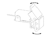
【解決手段】軸支片2により挟み込まれ、可動片10の一端が回動可能に軸支されている。可動片10は内部が中空の半円筒状に形成されており、先端部にはスリット13が、後部には大きな開放孔が形成されている。また可動片10の内壁には断面I字形状の上歯部13が形成されている。可動片10のもう一端には、断面コ字形状のロックレバー体20が鞍状に被せられ、軸12によって回動可能に軸支されている。ロックレバー体20の開放端にはツマミ部が形成され、また軸12の近傍には、ロックレバー体20に対して回動可能に、U字状のフック21が軸支されている。
【選択図】 図1
Description
【発明の属する技術分野】
本発明は、屋外または屋内の電子通信機器に配線する光ファイバケーブルの接続固定具に関し、特に光ファイバケーブル線材のテンションメンバーを把持固定するテンションメンバー固定具に関する。
【0002】
【従来の技術】
心線とテンションメンバーを有する光ファイバケーブルの接続に際しては、テンションメンバーを把持固定することが不可欠である。このため従来では、光ファイバケーブル接続用収納ケースにねじ穴を形成し、このねじ穴に螺合するねじ部材にテンションメンバーの端部を巻き付けた後、工具を用いて固定する処理が一般的であった。
【0003】
しかしながら、従来の光ファイバケーブルの端部処理のためにはケーブル被膜の剥離やねじに巻き付けるための曲げ加工などが必要となる。そこで心線を取り出す際には、この加工分を見越して光ファイバケーブルを長めに切断し、固定処理の際にはテンションメンバーを心線から裂いて先端部の被覆を剥がし、露出したテンションメンバー端部をねじに巻き付け固定する作業が行われていたが、各ケーブルに対してこのような作業を行うことは工数面で多大な負担を作業者に強いるものであった。
【0004】
また、ねじ部材は時間経過に伴い緩みを生じやすく、固定されたテンションメンバーが外れるおそれがあるという問題もあった。
【0005】
このような問題を解消するため、例えば特開平9−311229号公報「光ケーブル固定具」に記載された技術に代表される、固定処理が簡易でかつ外れにくいテンションメンバー固定具も提供されている。以下この先行技術について図6を用いて内容を簡単に説明する。
【0006】
連結棒上に立設状態に固着された固定部101に、回転プレート102が軸支ねじ103によって、テンションメンバー30に対して垂直の軸線をもって回転可能に軸支されている。この回転プレート102は概略長方形の高い剛性を有する板材であり、長手方向の一端に軸支ねじ103の貫通する軸穴104が、また長手方向の他端には片側の長辺から凹字状に切り欠かれた抜き穴105がそれぞれ形成されている。この抜き穴105は、固定部101に対して軸支ねじ103と同様に螺合された係合ねじ106の径よりわずかに広い幅で、回転プレート102を回転させた際、係合ねじ106とわずかな緩みをもって嵌合するような位置に形成されている。テンションメンバー30の把持固定時は、回転プレート102を回転させて係合ねじ106に係合させた後、軸支ねじ103および係合ねじ106を締め付けて、回転プレート102の回転を規制する。この回転プレート102と固定部101の間隙にテンションメンバー30を挟み込み、軸支ねじ103および係合ねじ106を更に締め付けることによってテンションメンバー30が固定される。
【0007】
【発明が解決しようとする課題】
しかしながら、上述した従来のテンションメンバー固定具では、端部をねじに直接巻き付ける構成は採っていないものの、テンションメンバー固定の手段としてはねじが使用されているため、固定および固定解除時にはねじの締め付け/緩め作業が発生していた。この作業については締結用の工具が必要とされ、またある程度の工数が割かれることは避けがたかった。
【0008】
また多数のねじの締め付けを行わなければならない場合、作業効率を考えれば全てのねじを同種のもので揃えることが望ましいが、これは反面、ねじの締め忘れという事態を引き起こし易くする一つの要因となっていた。
【0009】
さらに、テンションメンバーの端部自体は挟み込むことで押さえられるが、装置内においてテンションメンバーの先端が剥き出しとなっており、この先端が工具等と接触して傷ついたり、ショートを引き起こしたりするケースが皆無とは言えず、光ファイバケーブル保護の面で一抹の不安を残すものであった。
【0010】
本発明は、このような課題を解消し、工具を必要とせず簡易に固定作業が実現され、しかも固定作業がそのままテンションメンバー端部の保護作業に繋がる構造をもつテンションメンバー固定具を提供することを目的としている。
【0011】
【課題を解決するための手段】
以上の課題を鑑み、本発明のテンションメンバー固定具は、装置本体に固定され、テンションメンバーを載置する下歯部が形成されたベースと、前記ベースの一端の両脇部分に垂直に屹立して形成される一対の軸支持片と、前記一対の軸支持片に挟み込まれるように前記ベースの前後方向に回動可能に軸支され、内壁の前記下歯部と対応する位置に上歯部が形成された中空半筒状の可動体と、前記可動体の自由端側に載置され、該可動体に対して揺動可能に一端部を軸支された鞍型形状のロックレバー体と、前記ロックレバー体を両脇から挟みこんで枢着されたリング状のフックとにより構成され、前記テンションメンバーを前記ベース及び前記可動体の間に挿入し、前記フックを前記ベースに架け渡して前記ロックレバー体を押し倒すことにより、該テンションメンバーを前記上歯部と前記下歯部で挟持固定することを特徴としている。
【0012】
また、本発明の第二の構成例としては、上述の構成に加えて前記ベースの、前記軸支持片が形成されていない側にテンションメンバー端保護壁が垂直に屹立して形成されていることを特徴としている。
【0013】
さらに、本発明の第三の構成例としては、第一あるいは第二の構成例に加えて、前記可動体に前記テンションメンバーをガイドするスリットを形成してなることを特徴としている。
【0014】
【特許文献1】
特開平9−311229号公報
【0015】
【発明の実施の形態】
以下、本発明の実施形態について、図面を参照して詳細に説明する。
図1は本発明のテンションメンバー固定具の構成を示す斜視図である。細長い板状の鋼材により、固定部1が形成されている。固定部1の片側は鉤状に屈曲し、先端部分は保護壁4として、段状となっている部分の高い方の段の水平面を若干越えるよう垂直方向に屹立している。
【0016】
固定部1の水平部分の高い方の段には、固定用のネジ穴6が長手方向に並んで2つ穿設されており、このネジ穴の間に断面L字形状の下歯部5が設けられている。また、固定部1の高い段の両脇には、軸支片2が形成されている。そして水平部分の低い段には、蒲鉾型に屈曲された凹溝3が形成されている。
【0017】
固定部1の両軸支片2により挟み込まれ、可動片10の一端が軸11によって回動可能に軸支されている。可動片10は内部が中空の半円筒状に形成されており、その先端部(図中右側)にはスリット13が、そして後部(図中左側)には大きな開放孔が形成されている。また、可動片10の内壁には、図3に示すように、可動片10が固定部1に対して覆い被さる状態まで回動したとき、上下方向には固定部1に形成された下歯部5との間にわずかな間隙を残し、固定部1の長手方向には若干ずれつつ噛み合うような位置関係で、断面I字形状の上歯部13が形成されている。
【0018】
可動片10のもう一端には、断面コ字形状のロックレバー体20が鞍状に被せられ、軸12によって回動可能に軸支されている。ロックレバー体20の開放端にはツマミ部が形成され、また軸12の近傍には、ロックレバー体20に対して回動可能に、U字状のフック21が軸支されている。
【0019】
続いて本発明のテンションメンバー固定具の固定動作について、図面を参照して説明する。
【0020】
固定部1を、装置本体(図示せず)に対し、ネジ等の締結手段により固定する。この状態から図4に示すように、可動片10を開放側(図中における反時計回り)に回動させ、光ファイバケーブル30を、後端部分の開放孔から、固定部1に形成された下歯部5の上を通過し、さらにスリット14を通して先端のテンションメンバーが保護壁4に突き当たる状態になるまで挿入する。スリット14はテンションメンバーの径よりわずかに広い幅を有しており、またスリット14は保護壁4先端部分の水平面よりわずかに低い位置にまで切り込みが入れられている。
【0021】
光ファイバケーブル30を挿入した後、可動片10を時計回りに回動させると、挿入された光ファイバケーブル30が可動片10内壁の上歯部13と下歯部5とによって挟持される。これにより光ファイバケーブル30の抜けが防止される。このときロックレバー体20を、図5に示すように、時計回り方向へわずかな傾きをもって回動させ、保護壁4をフック21にくぐらせる。さらにロックレバー体21を時計回りに回動させると、フック21は固定部1の水平下段部分に形成された凹溝3と嵌合する。
【0022】
この状態から、ロックレバー体20を反時計回りに回動させると、フック21の先端は固定部1の凹溝3と嵌合したまま、ロックレバー体20のみが回動し、最終的には図2に示すように、可動片10が連結されたロックレバー体20と固定部1とで挟み込まれて固定される。この際、テンションメンバーの先端部分は保護壁によって保護され、またスリットによってテンションメンバー自体の不要なばたつき動作も規制されており、工具等と接触して傷ついたり、ショートを起こしたりすることが防止される。
【0023】
この固定状態を解除する際には、ロックレバー体20に形成されたつまみ部を持ち、図5における時計回り方向に回動させてフック21と凹溝3の嵌合を解除し、しかる後にフック21を反時計回りに回動させ、固定部1との連結状態を解除する。これによって可動片10が反時計回りに回転可能となり、上歯部13と下歯部5による光ファイバケーブル30の挟持状態が解除される。
【0024】
なお、本実施形態においては固定部1、可動片10およびロックレバー体20が鋼材によって形成されている例について説明してきたが、この素材についてはプラスティック等の、従来の固定具の構成材料として既知であり、かつ本固定具に必要とされる弾性や加工性の条件を満たし得る素材を適宜選択可能することが可能である。
【0025】
また、本実施形態においては垂直に屹立した保護壁の例について説明してきたが、テンションメンバー先端に対して庇状になるよう、さらに内側に折り曲げる構成としてもよい。さらに、本実施形態においてはフックと凹溝の嵌合によりロックレバー体と固定部の連結を実現しているが、フックに凸状のピン、固定部にこのピン径よりわずかに径の広い位置決め用の穴を形成するなど、この種の締結機構で用いられる既知の嵌合手段を適宜選択可能なことについても言うまでもない。
【0026】
【発明の効果】
以上説明してきたとおり、本発明のテンションメンバー固定具によれば、固定部とロックレバーの連結で可動片を挟み込み、この可動片と固定部の間でテンションメンバーを固定するという構造、及び固定作業がそのままテンションメンバー端部の保護作業に繋がるという構造を採っているため、テンションメンバーの固定/解除動作及び保護動作を、なんらの工具を必要とせず、ロックレバーの操作のみで行い得るという効果を奏する。
【0027】
また、上歯部と下歯部の間隙や配置、可動片及びロックレバーに形成する軸穴の配置等の要素によって、同一の固定具であればロックレバーの操作のみで一様なテンションでの固定が行えるという効果も奏する。これらのことにより、作業効率を大幅に向上させることが可能となる。
【図面の簡単な説明】
【図1】本発明のテンションメンバー固定具の実施形態における外観斜視図である。
【図2】本発明の実施形態における正面図である。
【図3】図1におけるA−A’断面図である。
【図4】テンションメンバー固定具による、テンションメンバーのロック解除状態を示す斜視図である。
【図5】テンションメンバーのロック動作を示す斜視図である。
【図6】従来のテンションメンバー固定具の構成を示す図である。
【符号の説明】
1 固定部
2 軸支片
3 凹溝
4 保護壁
5 下歯部
6 ネジ穴
10 可動片
11 軸
12 軸
13 上歯部
14 スリット
20 ロックレバー体
21 フック
30 光ファイバケーブル
Claims (3)
- 装置本体に固定され、テンションメンバーを載置する下歯部が形成されたベースと、
前記ベースの一端の両脇部分に垂直に屹立して形成される一対の軸支持片と、
前記一対の軸支持片に挟み込まれるように前記ベースの前後方向に回動可能に軸支され、内壁の前記下歯部と対応する位置に上歯部が形成された中空半筒状の可動体と、
前記可動体の自由端側に載置され、該可動体に対して揺動可能に一端部を軸支された鞍型形状のロックレバー体と、
前記ロックレバー体を両脇から挟みこんで枢着されたリング状のフックとにより構成され、
前記テンションメンバーを前記ベース及び前記可動体の間に挿入し、前記フックを前記ベースに架け渡して前記ロックレバー体を押し倒すことにより、該テンションメンバーを前記上歯部と前記下歯部で挟持固定することを特徴とするテンションメンバー固定具。 - 前記ベースの、前記軸支持片が形成されていない側に、
テンションメンバー端保護壁が垂直に屹立して形成されていることを特徴とする、請求項1記載のテンションメンバー固定具。 - 前記可動体に前記テンションメンバーをガイドするスリットを形成してなることを特徴とする、請求項1もしくは請求項2記載のテンションメンバー固定具。
Priority Applications (1)
| Application Number | Priority Date | Filing Date | Title |
|---|---|---|---|
| JP2003188818A JP2005024789A (ja) | 2003-06-30 | 2003-06-30 | テンションメンバー固定具 |
Applications Claiming Priority (1)
| Application Number | Priority Date | Filing Date | Title |
|---|---|---|---|
| JP2003188818A JP2005024789A (ja) | 2003-06-30 | 2003-06-30 | テンションメンバー固定具 |
Publications (1)
| Publication Number | Publication Date |
|---|---|
| JP2005024789A true JP2005024789A (ja) | 2005-01-27 |
Family
ID=34187230
Family Applications (1)
| Application Number | Title | Priority Date | Filing Date |
|---|---|---|---|
| JP2003188818A Pending JP2005024789A (ja) | 2003-06-30 | 2003-06-30 | テンションメンバー固定具 |
Country Status (1)
| Country | Link |
|---|---|
| JP (1) | JP2005024789A (ja) |
Cited By (16)
| Publication number | Priority date | Publication date | Assignee | Title |
|---|---|---|---|---|
| US7467896B2 (en) | 2000-05-26 | 2008-12-23 | Corning Cable Systems Llc | Fiber optic drop cables and preconnectorized assemblies |
| US7785015B2 (en) | 2000-05-26 | 2010-08-31 | Corning Cable Systems Llc | Fiber optic drop cables and preconnectorized assemblies |
| US9239441B2 (en) | 2000-05-26 | 2016-01-19 | Corning Cable Systems Llc | Fiber optic drop cables and preconnectorized assemblies having toning portions |
| US10359577B2 (en) | 2017-06-28 | 2019-07-23 | Corning Research & Development Corporation | Multiports and optical connectors with rotationally discrete locking and keying features |
| US10379298B2 (en) | 2017-06-28 | 2019-08-13 | Corning Research & Development Corporation | Fiber optic connectors and multiport assemblies including retention features |
| EP3537198A1 (en) * | 2018-03-05 | 2019-09-11 | Corning Research & Development Corporation | Fibre-optic cable fanout |
| US11187859B2 (en) | 2017-06-28 | 2021-11-30 | Corning Research & Development Corporation | Fiber optic connectors and methods of making the same |
| US11294133B2 (en) | 2019-07-31 | 2022-04-05 | Corning Research & Development Corporation | Fiber optic networks using multiports and cable assemblies with cable-to-connector orientation |
| US11536921B2 (en) | 2020-02-11 | 2022-12-27 | Corning Research & Development Corporation | Fiber optic terminals having one or more loopback assemblies |
| US11604320B2 (en) | 2020-09-30 | 2023-03-14 | Corning Research & Development Corporation | Connector assemblies for telecommunication enclosures |
| US11686913B2 (en) | 2020-11-30 | 2023-06-27 | Corning Research & Development Corporation | Fiber optic cable assemblies and connector assemblies having a crimp ring and crimp body and methods of fabricating the same |
| US11880076B2 (en) | 2020-11-30 | 2024-01-23 | Corning Research & Development Corporation | Fiber optic adapter assemblies including a conversion housing and a release housing |
| US11927810B2 (en) | 2020-11-30 | 2024-03-12 | Corning Research & Development Corporation | Fiber optic adapter assemblies including a conversion housing and a release member |
| US11994722B2 (en) | 2020-11-30 | 2024-05-28 | Corning Research & Development Corporation | Fiber optic adapter assemblies including an adapter housing and a locking housing |
| US12019279B2 (en) | 2019-05-31 | 2024-06-25 | Corning Research & Development Corporation | Multiports and other devices having optical connection ports with sliding actuators and methods of making the same |
| US12271040B2 (en) | 2017-06-28 | 2025-04-08 | Corning Research & Development Corporation | Fiber optic extender ports, assemblies and methods of making the same |
-
2003
- 2003-06-30 JP JP2003188818A patent/JP2005024789A/ja active Pending
Cited By (53)
| Publication number | Priority date | Publication date | Assignee | Title |
|---|---|---|---|---|
| US7467896B2 (en) | 2000-05-26 | 2008-12-23 | Corning Cable Systems Llc | Fiber optic drop cables and preconnectorized assemblies |
| US7785015B2 (en) | 2000-05-26 | 2010-08-31 | Corning Cable Systems Llc | Fiber optic drop cables and preconnectorized assemblies |
| US7881576B2 (en) | 2000-05-26 | 2011-02-01 | Corning Cable Systems Llc | Fiber optic drop cables and preconnectorized assemblies |
| US7918609B2 (en) | 2000-05-26 | 2011-04-05 | Corning Cable Systems Llc | Fiber optic drop cables and preconnectorized assemblies |
| US9239441B2 (en) | 2000-05-26 | 2016-01-19 | Corning Cable Systems Llc | Fiber optic drop cables and preconnectorized assemblies having toning portions |
| US10114176B2 (en) | 2000-05-26 | 2018-10-30 | Corning Optical Communications LLC | Fiber optic drop cables and preconnectorized assemblies |
| US11536913B2 (en) | 2017-06-28 | 2022-12-27 | Corning Research & Development Corporation | Fiber optic connectors and connectorization employing adhesive admitting adapters |
| US11579377B2 (en) | 2017-06-28 | 2023-02-14 | Corning Research & Development Corporation | Compact fiber optic connectors, cable assemblies and methods of making the same with alignment elements |
| US10386584B2 (en) | 2017-06-28 | 2019-08-20 | Corning Research & Development Corporation | Optical connectors with locking and keying features for interfacing with multiports |
| US12353025B2 (en) | 2017-06-28 | 2025-07-08 | Corning Optical Communications LLC | Multiports having a connection port insert and methods of making the same |
| US10429593B2 (en) | 2017-06-28 | 2019-10-01 | Corning Research & Development Corporation | Fiber optic connectors and connectorization employing adapter extensions and/or flexures |
| US10605998B2 (en) | 2017-06-28 | 2020-03-31 | Corning Research & Development Corporation | Fiber optic connectors and connectorization employing adhesive admitting adapters |
| US10802228B2 (en) | 2017-06-28 | 2020-10-13 | Corning Research & Development Corporation | Fiber optic connectors and multiport assemblies including retention features |
| US10809463B2 (en) | 2017-06-28 | 2020-10-20 | Corning Research & Development Corporation | Multiports and optical connectors with rotationally discrete locking and keying features |
| US11187859B2 (en) | 2017-06-28 | 2021-11-30 | Corning Research & Development Corporation | Fiber optic connectors and methods of making the same |
| US11215768B2 (en) | 2017-06-28 | 2022-01-04 | Corning Research & Development Corporation | Fiber optic connectors and connectorization employing adhesive admitting adapters |
| US11262509B2 (en) | 2017-06-28 | 2022-03-01 | Corning Research & Development Corporation | Compact fiber optic connectors having multiple connector footprints, along with cable assemblies and methods of making the same |
| US11287582B2 (en) | 2017-06-28 | 2022-03-29 | Corning Research & Development Corporation | Compact fiber optic connectors, cable assemblies and methods of making the same |
| US11287581B2 (en) | 2017-06-28 | 2022-03-29 | Corning Research & Development Corporation | Compact fiber optic connectors, cable assemblies and methods of making the same |
| US12353024B2 (en) | 2017-06-28 | 2025-07-08 | Corning Research & Development Corporation | Multiports and optical connectors with rotationally discrete locking and keying features |
| US11300735B2 (en) | 2017-06-28 | 2022-04-12 | Corning Research & Development Corporation | Compact fiber optic connectors having multiple connector footprints, along with cable assemblies and methods of making the same |
| US11307364B2 (en) | 2017-06-28 | 2022-04-19 | Corning Research & Development Corporation | Compact fiber optic connectors having multiple connector footprints, along with cable assemblies and methods of making the same |
| US11460646B2 (en) | 2017-06-28 | 2022-10-04 | Corning Research & Development Corporation | Fiber optic connectors and multiport assemblies including retention features |
| US11493700B2 (en) | 2017-06-28 | 2022-11-08 | Corning Research & Development Corporation | Compact fiber optic connectors, cable assemblies and methods of making the same |
| US11493699B2 (en) | 2017-06-28 | 2022-11-08 | Corning Research & Development Corporation | Multifiber fiber optic connectors, cable assemblies and methods of making the same |
| US11531168B2 (en) | 2017-06-28 | 2022-12-20 | Corning Research & Development Corporation | Fiber optic connectors having a keying structure and methods of making the same |
| US10359577B2 (en) | 2017-06-28 | 2019-07-23 | Corning Research & Development Corporation | Multiports and optical connectors with rotationally discrete locking and keying features |
| US12298568B2 (en) | 2017-06-28 | 2025-05-13 | Corning Research & Development Corporation | Fiber optic connectors and multiport assemblies including retention features |
| US11543600B2 (en) | 2017-06-28 | 2023-01-03 | Corning Research & Development Corporation | Compact fiber optic connectors having multiple connector footprints, along with cable assemblies and methods of making the same |
| US10379298B2 (en) | 2017-06-28 | 2019-08-13 | Corning Research & Development Corporation | Fiber optic connectors and multiport assemblies including retention features |
| US12276846B2 (en) | 2017-06-28 | 2025-04-15 | Corning Research & Development Corporation | Compact fiber optic connectors, cable assemblies and methods of making the same |
| US12271040B2 (en) | 2017-06-28 | 2025-04-08 | Corning Research & Development Corporation | Fiber optic extender ports, assemblies and methods of making the same |
| US11703646B2 (en) | 2017-06-28 | 2023-07-18 | Corning Research & Development Corporation | Multiports and optical connectors with rotationally discrete locking and keying features |
| US12174432B2 (en) | 2017-06-28 | 2024-12-24 | Corning Research & Development Corporation | Fiber optic connectors and connectorization employing adhesive admitting adapters |
| US11886017B2 (en) | 2017-06-28 | 2024-01-30 | Corning Research & Development Corporation | Multiports and other devices having connection ports with securing features and methods of making the same |
| US11906792B2 (en) | 2017-06-28 | 2024-02-20 | Corning Research & Development Corporation | Compact fiber optic connectors having multiple connector footprints, along with cable assemblies and methods of making the same |
| US11914198B2 (en) | 2017-06-28 | 2024-02-27 | Corning Research & Development Corporation | Compact fiber optic connectors having multiple connector footprints, along with cable assemblies and methods of making the same |
| US11914197B2 (en) | 2017-06-28 | 2024-02-27 | Corning Research & Development Corporation | Compact fiber optic connectors having multiple connector footprints, along with cable assemblies and methods of making the same |
| US12092878B2 (en) | 2017-06-28 | 2024-09-17 | Corning Research & Development Corporation | Fiber optic connectors having a keying structure and methods of making the same |
| US11940656B2 (en) | 2017-06-28 | 2024-03-26 | Corning Research & Development Corporation | Compact fiber optic connectors, cable assemblies and methods of making the same |
| US11966089B2 (en) | 2017-06-28 | 2024-04-23 | Corning Optical Communications, Llc | Multiports having connection ports formed in the shell and associated securing features |
| US12013578B2 (en) | 2017-06-28 | 2024-06-18 | Corning Research & Development Corporation | Multifiber fiber optic connectors, cable assemblies and methods of making the same |
| EP3537198A1 (en) * | 2018-03-05 | 2019-09-11 | Corning Research & Development Corporation | Fibre-optic cable fanout |
| US12019279B2 (en) | 2019-05-31 | 2024-06-25 | Corning Research & Development Corporation | Multiports and other devices having optical connection ports with sliding actuators and methods of making the same |
| US11294133B2 (en) | 2019-07-31 | 2022-04-05 | Corning Research & Development Corporation | Fiber optic networks using multiports and cable assemblies with cable-to-connector orientation |
| US11536921B2 (en) | 2020-02-11 | 2022-12-27 | Corning Research & Development Corporation | Fiber optic terminals having one or more loopback assemblies |
| US12019285B2 (en) | 2020-09-30 | 2024-06-25 | Corning Research & Development Corporation | Connector assemblies for telecommunication enclosures |
| US11604320B2 (en) | 2020-09-30 | 2023-03-14 | Corning Research & Development Corporation | Connector assemblies for telecommunication enclosures |
| US11994722B2 (en) | 2020-11-30 | 2024-05-28 | Corning Research & Development Corporation | Fiber optic adapter assemblies including an adapter housing and a locking housing |
| US11927810B2 (en) | 2020-11-30 | 2024-03-12 | Corning Research & Development Corporation | Fiber optic adapter assemblies including a conversion housing and a release member |
| US11880076B2 (en) | 2020-11-30 | 2024-01-23 | Corning Research & Development Corporation | Fiber optic adapter assemblies including a conversion housing and a release housing |
| US11686913B2 (en) | 2020-11-30 | 2023-06-27 | Corning Research & Development Corporation | Fiber optic cable assemblies and connector assemblies having a crimp ring and crimp body and methods of fabricating the same |
| US12345927B2 (en) | 2020-11-30 | 2025-07-01 | Corning Research & Development Corporation | Fiber optic adapter assemblies including a conversion housing and a release housing |
Similar Documents
| Publication | Publication Date | Title |
|---|---|---|
| JP2005024789A (ja) | テンションメンバー固定具 | |
| JP5268536B2 (ja) | 電線支持具及び活線切分工具 | |
| JP2007202288A (ja) | ケーブル間隔保持具 | |
| JP5792243B2 (ja) | 間接活線作業用工具 | |
| JP3198314U (ja) | 引留クランプ把持具 | |
| JP2002176901A (ja) | 鳥害防止装置 | |
| KR101790071B1 (ko) | 케이블 권취장치 | |
| JP2010239107A (ja) | 電気機器収納用箱体 | |
| KR101070398B1 (ko) | 와이어 테이핑장치 | |
| JP3476105B2 (ja) | 活線用工具の取付け具 | |
| JP2011205890A (ja) | 電線設備具 | |
| JP4600976B2 (ja) | ポール用取付金具 | |
| JP5377034B2 (ja) | 防巣具取付装置 | |
| JP4953133B2 (ja) | 接地用具 | |
| JP3115358U (ja) | ドロップ支持線の端部収納装置 | |
| JP2939210B2 (ja) | 電線類仮預け具 | |
| JP3946029B2 (ja) | フィルターユニット | |
| JP2010280501A (ja) | 外出し、中出し自在なる平置型組立式携帯電線リール | |
| JP3444076B2 (ja) | チェーンバイス装置 | |
| JP3673125B2 (ja) | 通信機器用収納架 | |
| JPH0514554Y2 (ja) | ||
| JP4990673B2 (ja) | 回路遮断器 | |
| JP3957566B2 (ja) | 天井埋込みスピーカ取付け器具、かかる取付け器具を含む天井埋込みスピーカ取付けセット及びかかる取付けセットを用いた天井埋込みスピーカ取付方法 | |
| JPH05252627A (ja) | 電線絶縁保護管の端末固定具 | |
| JP2001292521A (ja) | ケーブル接続箱支持装置 |
Legal Events
| Date | Code | Title | Description |
|---|---|---|---|
| RD01 | Notification of change of attorney |
Free format text: JAPANESE INTERMEDIATE CODE: A7421 Effective date: 20050401 |
|
| RD01 | Notification of change of attorney |
Free format text: JAPANESE INTERMEDIATE CODE: A7421 Effective date: 20050414 |
|
| A621 | Written request for application examination |
Free format text: JAPANESE INTERMEDIATE CODE: A621 Effective date: 20060518 |
|
| RD01 | Notification of change of attorney |
Free format text: JAPANESE INTERMEDIATE CODE: A7421 Effective date: 20070125 |
|
| A977 | Report on retrieval |
Free format text: JAPANESE INTERMEDIATE CODE: A971007 Effective date: 20070710 |
|
| A131 | Notification of reasons for refusal |
Free format text: JAPANESE INTERMEDIATE CODE: A131 Effective date: 20070731 |
|
| A02 | Decision of refusal |
Free format text: JAPANESE INTERMEDIATE CODE: A02 Effective date: 20071204 |