【0001】
【発明の属する技術分野】
本発明は、プロジェクター,プロジェクションTV等の基幹部品としての反射型液晶表示素子に係り、特に、使用時の温度上昇による液晶セル厚の変化を抑制すると共に、良好な放熱を可能にして、輝度ムラなどの表示品質の低下を防止するのに好適な反射型液晶表示素子に関するものである。
【0002】
【従来の技術】
プロジェクターやプロジェクションTVの表示素子として、液晶表示素子が広く用いられている。近年、特に、マトリクス状に配置された反射電極とそれに電圧を供給するためのCMOSトランジスタ駆動回路とを配したシリコン基板と、共通電極を形成した透明ガラス基板とを対向して貼り合わせ、その間に液晶を封止したLCOS(Liquid Crystal On Silicon)素子と呼ばれる反射型液晶表示素子が、その表示画像品質の高さで注目されている。
【0003】
このような反射型液晶表示素子は、液晶層をシリコン基板と透明ガラス基板との間に封止して形成した反射型液晶表示セル(以下、単に液晶セルともいう)を、金属製又は樹脂製のパッケージ(ハウジング)にフレキシブルプリント基板(FPC)と共に収納したものより構成されている。
【0004】
図6は、従来例の反射型液晶表示素子を示す概略断面構成図である(例えば、特許文献1参照。)。
同図に示すように、反射型液晶表示素子20は、プレート11と、プレート11内部の所定位置に配置された反射型液晶表示セル10と、透明ガラスからなる窓材14とから構成されている。
【0005】
反射型液晶表示セル10においては、透明ガラス基板1とシリコン基板2とをその間に液晶(表示せず)を封止して貼り合わせてある。
透明ガラス基板1の液晶と接する面には、透明電極(図示しない)を形成してあり、他方の面(窓材14側)には、反射防止膜(図示しない)を形成してある。
【0006】
シリコン基板1上には、マトリクス状に配置したスイッチングトランジスタ(図示しない)を形成してあり、さらにその上に絶縁層を介して、各スイッチングトランジスタによって駆動される各画素電極(反射電極)(図示しない)を形成してある。ここで、シリコン基板2の画素電極側が透明ガラス基板1に対向する。
【0007】
ガラス基板1とシリコン基板2は、間に封入する液晶層のセルギャップを決めるスペーサを混入したシール接着剤で固着されている。
反射型液晶表示セル10のシリコン基板2を、プレート11の底面部11aに対向させて、その透明ガラス基板1の4隅を、UV接着剤からなる接着層13により、プレート11の中間部11bに接着されている。
【0008】
アルミニウムからなるプレート11には、複数の冷却フィン11dを設けてある。
一方、プレートの底面部11aとシリコン基板2の間には、それぞれに接するようにシリコーンゲル剤(以下,単にシリコーンゲルともいう)単位12を塗布してある。このシリコーンゲル剤12は、プレート11と反射型液晶表示セル10の位置決めを保持する。シリコーンゲル剤12としては、高熱伝導性を有する材料を使用する。
プレート11の上面部11cには、プレート11の内部に固定配置した反射型液晶表示セル10の防塵のために、透明ガラスの窓材14を密着配置してある。
【0009】
【特許文献1】
特開2002−296568号公報(第3−5頁、第1−5図)
【0010】
【発明が解決しようとする課題】
ところで、反射型液晶表示素子は、プロジェクタ装置等に組み込まれて、光源より読出し光が照射されると、その光の一部を吸収して、温度が上昇する。
このとき、読出し光が通過する反射型液晶表示セルに、接合部材との間の熱膨張率との差により、応力が生じたり、セルギャップのムラが生じると、これらは、不均一な複屈折を発生させ、表示画像の品質を劣化させる。
【0011】
上述した従来例の反射型液晶表示素子は、このような温度上昇に係る放熱及び熱膨張の問題を考慮したものであったが、表示画像のいっそうの高密度化、高輝度化が求められて、高出力の光源が使用されるに至っては、温度上昇により、良好な画像品質を保持するのが困難となっている。
【0012】
すなわち、シリコーンゲル12によって、反射型液晶表示セル(以下,単に液晶表示セルともいう)10のシリコン基板2とアルミニウムからなるプレート11を接着固定しており、液晶表示セル10で発生した熱を、シリコーンゲル12及びプレート11の放熱フィン11dを通して放熱する構造となっているが、高出力の読出し光照射により一層高温となると、シリコン基板2とプレート11を構成するアルミニウムとの熱膨張率の差が大きいため、大きな応力が発生して、液晶表示セル10に複屈折を生じることにより、表示画像の品質が劣化してしまう。また、反射型液晶表示セル10の作製時及びパッケージ工程において発生するセル厚(ギャップ)の不均一性は、液晶表示セル10が高温になると一層大きくなり、表示画像の品質を劣化させるという問題がある。
【0013】
パッケージ工程及びプロジェクタ装置使用時に、反射型液晶表示セルのセル厚が変動する要因として、パッケージ工程においては、反射型液晶表示セルを固定する際に、歪んだ状態で反射型液晶表示セルを固定することによって発生する応力によって起きるセル厚の変動であり、プロジェクタ装置使用時においては、温度上昇によって生じる反射型液晶表示セルとこれを配置固定するパッケージ材料との熱膨張率差によるセル厚変動であり、これらの問題の解決が求められている。
【0014】
そこで、本発明は、上記問題を解決して、パッケージ工程及び動作状態で発生する液晶セルの厚み変動を抑制し、高品位の画像を表示する反射型液晶表示素子を提供することを目的とする。
【0015】
【課題を解決するための手段】
上記目的を達成するための手段として、本発明は、シリコン基板2Aと、透明基板1Aと、前記シリコン基板及び前記透明基板間に封止された液晶3とからなる反射型液晶表示セル10Aと、前記反射型液晶表示セル10Aを前記シリコン基板2A側で接着剤(シリコーンゲル剤25)によりその一方の面上に接着固定するセル固定部材(セルベース40)と、前記セル固定部材の他方の面上に固定配置する、前記反射型液晶表示セルを前記セル固定部材を介して冷却するためのヒートシンク50と、前記反射型液晶表示セルに光を導入するための光学系と前記セル固定部材との間に配置され、前記反射型液晶表示セルが前記光学系に対して所定配置となるように前記セル固定部材を前記光学系に配置固定するための固定部材(セルハウジング30)とからなる反射型液晶表示素子において、
前記セル固定部材を前記固定部材に3点支持で固定すると共に、前記セル固定部材を、前記反射型液晶表示セルを構成する前記シリコン基板の熱膨張率と略等しい熱膨張率を有する部材より構成したことを特徴とする反射型液晶表示素子である。
【0016】
【発明の実施の形態】
以下、本発明の実施の形態につき、好ましい実施例により、図面を参照して説明する。
【0017】
<第1実施例>
図1は、本発明の反射型液晶表示素子の第1実施例を示す概略断面構成図である。
図2は、本発明の反射型液晶表示素子の第1実施例を示す概略分解斜視構成図である。
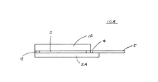
図3は、本発明の反射型液晶表示素子に係る反射型液晶表示セルを示す概略断面構成図である。
【0018】
図3に示すように、以下の本第1実施例も含めて各実施例に係る反射型液晶表示セル10Aは、シリコン基板2Aと、透明ガラス基板1Aと、シリコン基板2Aと透明ガラス基板1Aとを対向させてスペーサ4を介して配置した間隙に封止した液晶3と、シリコン基板2A上に配置したフレキシブル配線板5とから構成されている。
【0019】
シリコン基板2Aの液晶3側の面上には、画素に対応してマトリクス状に、スイッチングトランジスタを含む駆動回路(図示しない)と、これによって信号電圧を印加される画素電極(図示しない)とが形成されている。画素電極は、ガラス基板1A側から入射する読出し光を反射する反射電極である。
透明ガラス基板1Aの液晶3側の面上には透明電極(図示しない)が、反対側の面上には反射防止膜(図示しない)がそれぞれ形成されている。
【0020】
シリコン基板2A上の駆動回路及びガラス基板1A上の透明電極は、フレキシブル配線板5に接続されており、回路部(図示しない)よりフレキシブル配線板5を通して電気信号が供給される。
スペーサ4の厚さは、例えば5μmであり、これが、反射型液晶表示セル10Aのセル厚となる。
【0021】
反射型液晶表示セル10Aの画像表示動作は、シリコン基板2A上に形成した駆動回路に接続する画素電極と、ガラス基板1A上に形成した透明電極間に、画像に対応した信号電圧を印加し、液晶3の偏光方向を変えることによって、ガラス基板1Aを通して液晶3に入射した後、画素電極で反射して出射する光の偏光方向を変えることによって行われる。反射型液晶表示セル10Aにおいて、画素は、2次元のマトリクス状に配置されているので、この画素を選択的に駆動することにより、2次元の画像表示を行うことができる。
【0022】
図1及び図2に示すように、反射型液晶表示セル10Aは、セルハウジング30に組み込まれて、反射型液晶表示素子20Aとして、プロジェクタ装置(図示しない)の色分解合成光学系(図示しない)に組み込まれる。
色分解合成光学系(図示しない)は、光源(図示しない)から出射される読出し光を、反射型液晶表示素子20Aの反射型液晶表示セル10Aに導き、反射型液晶表示セル10Aから出射される画像信号で変調された読出し光(画像光である)を、スクリーン(図示しない)に投射する機能を有する。
【0023】
図1及び2に示されるように、第1実施例の反射型液晶表示素子20Aは、ガラス窓材26の取り付けられたセルハウジング30と、セルハウジング30に取り付けられたセルベース40と、セルベース40にシリコーンゲル剤25によって固着された反射型液晶表示セル10Aと、セルベース40に放熱シート23を介して固定配置されたヒートシンク50より構成される。
【0024】
板状のセルベース40においては、一方の面は平坦にされており、他方の面側には、反射型液晶表示セル10Aを配置する凹部47が設けられている(場合により、特に、凹部を設けなくても良い)。セルベース40の大きさは例えば縦43mm(取付部42,43,44を除いた長さ)、横47mmとしたとき、厚さは、十分な剛性を確保できる1.9mmとしている。セルベース40はコバールより構成されている。コバールは、Co(17wt%)−Ni(29wt%)−Fe(bal)合金であり、その熱膨張率は49×10-7/°Cである。なお、コバールの熱伝導度は17W/m°Cである。
ちなみに、シリコン基板2Aの熱膨張率は32×10-7/°Cである。
また、ガラス基板1Aは、コーニング社製の#1737より構成されており、この熱膨張率は38×10-7/°Cである。
【0025】
反射型液晶表示セル10Aは、シリコン基板2Aをセルベース40に形成してある凹部47の底面47aに対向して、シリコーンゲル剤25で、セルベース40に接着固定されている。ここで、凹部47の側面47bが、反射型液晶表示セルに触れないように、凹部47は十分な大きさに形成されている。使用するシリコーンゲル剤25は,柔軟性の大きいものを用いており、例えば、信越シリコーン(株)製のKE1052が用いられる。シリコーンゲル剤25の厚さは、シリコン基板の4隅に配置した厚さ125μmのスペーサ24によって規制され、略125μmである。
【0026】
セルベース40の外周部には3箇所の取付部42,43,44が設けられている。取付部42,43,44には取付孔42a,43a,44aがそれぞれ設けられている。
【0027】
セルハウジング30は、例えば厚さ略5mmのSUS303より構成され、中央部に、矩形状の貫通部35を形成してある。貫通部35の広さは、非接触で反射型液晶表示セル10Aを収納するのに十分である。貫通部35の一部は、より狭い貫通部分である矩形状の窓材取付部39になっており、その窓材取付面39a上に、窓材26が接着固定されている。
【0028】
セルハウジング30の一方の面には、3箇所にスペーサ32,33,34が設けられており、これらのスペーサ32,33,34の露出した面は同一平面になるように精密研磨加工されている。スペーサ32,33,34には、取付ネジ孔32a,33a,34aがそれぞれ設けられている。これらの取付ネジ孔32a,33a,34aは、セルベース40に設けられた取付孔42a,43a,44aに対応している。
【0029】
反射型液晶表示セル10Aを凹部47の所定位置に接着固定したセルベース40はセルハウジング30に取付・固定される。取付は、3本のネジをセルベースの取付孔42a,43a,44aをそれぞれ通し、セルハウジング30の取付ネジ孔32a,33a,34aにそれぞれネジ止めすることによって行われる。3点支持で、セルベース40をセルハウジング30に固定しているので、セルベース40には、取付による捻り等が発生しない。
【0030】
従って、セルベース40の凹部にシリコーンゲル材25を介して接着されている反射型液晶表示セル10Aにも、取付によって、応力が発生することがなく、液晶セル厚は、正しく保持される。複屈折を発生することもない。反射型液晶表示セル10Aは、セルハウジング30とは非接触で保持されている。
【0031】
セルベース40は放熱シート23を介して、ヒートシンク50に配置されている。放熱シート23の片側には接着剤が塗布されており、セルベース40に放熱シートが接着されている。セルベース40とヒートシンク50は、放熱シート23を挟んで、互いに4隅で、所定の荷重のかかるバネにより圧着されて保持されている。
【0032】
ヒートシンク50の放熱シート23とは反対側には、ヒートシンク50の放熱を良好に行うための複数の放熱フィン52A1〜52Anが設けられている。ヒートシンク50は、アルミニウムから構成されており、その熱膨張率は220〜240×10-7/°Cである。なお、アルミニウムの熱伝導度は130〜230W/m°Cであり、剛性は70〜80GPaである。
【0033】
反射型液晶表示素子20Aは、色分解合成光学系の偏光ビームスプリッタ(図示しない)に、ガラス窓剤26を対向させて、セルハウジング30に取付・固定された取付部材(図示しない)を介して固定されている。
【0034】
このようにして液晶プロジェクタ装置を構成し、実際に動作させて,評価した。
本第1実施例の反射型液晶表示素子20Aにおける反射型液晶表示セル10Aのサイズは対角1.3インチ(アスペクト比4:3)であり、1画素のサイズは、12.9μm×12.9μmである。
用いた光学系は、スクリーン上で5000lm(ルーメン)の明るさを有するものであり、反射型液晶表示素子20Aへの入射光量は12Wである。
【0035】
表示品質として、位置ズレと均一性を評価した。スクリーン上に表示された3原色画像の位置ズレは、最大で0.6画素分であリ、良好であった。画面の明るさをスクリーンの中央部及び4隅の5箇所で比較したところ、明るさの均一性はムラがあるものの、判定は良であった。
また、反射型液晶表示セル10Aのガラス基板1Aの4隅の温度を測定したところ、50.2°Cと51.5°Cの範囲(温度差1.3°C)であった。
【0036】
<比較例>
上述の従来例の構成の反射型液晶表示素子20を、第1実施例におけると同様の色分解合成光学系にセットし、第1実施例と同様に評価した。
位置ズレは2.5画素分あり、表示品質としては、不良である。明るさの均一性は、ムラがあり不良であった。
また、反射型液晶表示セル10のガラス基板1の4隅の温度を測定したところ、48.1°Cと48.9°Cの範囲(温度差0.8°C)であった。
【0037】
<第2実施例>
図4は、本発明の反射型液晶表示素子の第2実施例を示す概略断面構成図である。
同図に示すように、第2実施例の反射型液晶表示素子20Bは、第1実施例の反射型液晶表示素子20Aにおいて、セルベース40に代えてセルベース40Aとした以外は第1実施例の反射型液晶表示素子20Aと同様に構成したものである。
【0038】
ここで、セルベース40Aは、セルベース40と機械的寸法は同様であり、構成する材料をコバールに代えて、金属基複合体としたものである。
金属基複合体(Metal Matrix Composite:MMCと略称する。)は、金属とセラミック粉末を焼結して形成した複合材料である。MMCとしては、PSS−50(セランクス(株)製)を用いている。このMMCの熱膨張率は28×10-7/°Cであり、その熱伝導度は175W/m°Cであり、剛性は280GPaである。
【0039】
この第2実施例の反射型液晶表示素子20Bを、第1実施例におけると同様の色分解合成光学系にセットし、第2実施例と同様に評価した。
位置ズレは0.3画素分あり、表示品質としては、良好である。明るさの均一性は、ムラがなく、良好であった。
また、反射型液晶表示セル10Aのガラス基板1Aの4隅の温度を測定したところ、48.3°Cと48.9°Cの範囲(温度差0.6°C)であった。
なお、MMCとしては、PSI−70(セランクス(株)製:熱膨張率が62×10-7/°C、熱伝導度が172W/m°C、剛性が265GPaである。)を用いた場合には、温度は48.2°Cから48.7°Cの範囲(温度差0.5°C)であり、位置ズレは、0.7画素分であり、均一性は良好であった。
【0040】
<第3実施例>
図5は、本発明の反射型液晶表示素子の第3実施例を示す概略断面構成図である。
同図に示すように、第3実施例の反射型液晶表示素子20Cは、第1実施例の反射型液晶表示素子20Aにおいて、セルベース40に代えて、セルベース40Aとし、放熱シート23とヒートシンク50との間に新たにペルチェ素子60を挿入固定した以外は、第1実施例の反射型液晶表示素子20Aと同様に構成してある。
【0041】
セルベース40Aは、上述の第2実施例の反射型液晶表示素子20Bで用いたものである。
ペルチェ素子60は、電流を流すことによって、一方の面の熱を他方の面に移動させるものである。
【0042】
この第3実施例の反射型液晶表示素子20Cを、第1実施例におけると同様の色分解合成光学系にセットし、第1実施例と同様に評価した。このときペルチェ素子60には、電流1Aを流しておいた。
位置ズレは0.3画素分あり、表示品質としては、良好である。明るさの均一性は、ムラがなく、良好であった。
また、反射型液晶表示セル10Aのガラス基板1Aの4隅の温度を測定したところ、33.5°Cと34.1°Cの範囲(温度差0.6°C)であった。第2実施例に比較して、反射型液晶表示セル10Aにおいて、約15°C温度低下することができた。
【0043】
本発明の反射型液晶表示素子20Aと比較例の反射型液晶表示素子20とを比較すると、比較例においては、光照射時における反射型液晶表示セル10の温度が48.1から48.9°Cであり、第1実施例における液晶表示セル10Aの温度である50.2〜51.5°Cより低く保たれている。にもかかわらず、表示品質が良好でない結果になっている。
【0044】
これは、少なくとも、温度上昇による液晶表示セル10自体の歪による影響は少ないものの、液晶表示セル10とプレート11との熱膨張率差が大きいことによる液晶表示セル10における歪の発生,及び4点で液晶表示セル10をプレートに固定するパッケージングにおける歪の発生により、液晶表示セル10のセル厚の変動が大きいためと考えられる。
【0045】
すなわち、アルミニウムを液晶表示セルの保持材料に用いた場合、熱伝導度が高いため液晶表示セルは均一に冷却されるが、シリコン基板に比較し熱膨張率が一桁大きいため、光学系に対する液晶表示セルの位置ずれが大きくなり、表示品質の低下を招く。また、熱膨張率差による応力が加わり、表示ムラも発生した。
【0046】
本発明の反射型液晶表示素子においては、(1)液晶表示セル10Aを配置するパッケージ(セルベース40)の材料に、液晶表示セル10A(特に密着するシリコン基板2A)と熱膨張率の近い材料(具体的にはコバール)を使用する、(2)パッケージ(コバール)に液晶表示セルを固着する際に、やわらかい物性を持つシリコーンゲルを使用する、(3)パッケージをパッケージ本体(セルハウジング30)に固定する際に3点支持としている。
これにより、本発明の反射型液晶表示素子20Aは、パッケージ工程でのセル厚変化およびプロジェクタ装置に装着した使用時における温度変動によるセル厚変動を抑制し、高品位の映像表示することが可能である。
【0047】
また、本発明の反射型液晶表示素子20Bにおいては、セルベースとして、シリコン基板の熱膨張率に近い熱膨張率を有し、且つ、熱伝導度の高い材料であるMMCを用いることにより、セルベースをセルハウジングに3点支持で固定することと相まって、一層良好な反射型液晶表示素子の表示品質を実現している。
【0048】
また、本発明の反射型液晶表示素子20Cにおいては,セルベースとヒートシンクの間にペルチェ素子を配置することにより、液晶表示セルの温度を低下させることができ、より高出力の光源を用いる高輝度の画像表示を可能とする。
ペルチェ素子は流す電流によって熱の移動を制御できる。従って、入射光量が大きくなり液晶表示セル(デバイスともいう)の温度が高くなった場合、また環境温度に応じてデバイスの温度が変化した場合でも、ペルチェ素子に流す電流値を制御することで、デバイス温度を一定温度以下にすることが出来る。また、温度センサーをセルベースなどに組み込むことで、デバイス温度を常に一定に保つ事も可能である。
【0049】
ここで、セルベース(パッケージ)を構成する材料の熱膨張率を28×10-7/°Cから62×10-7/°Cの範囲(シリコン基板の熱膨張率との比(セルベースの熱膨張率/シリコン基板の熱膨張率)では、0.8から1.9である。)とし、熱伝導度を20W/m°Cから175W/m°Cの範囲とすることで、反射型液晶表示素子の表示品質の低下を防止できる。
また、ペルチェ素子に代えて、水冷機構をセルベースとヒートシンクの間に設けても良い。
【0050】
【発明の効果】
以上説明したように、本発明は、請求項1記載によれば、セル固定部材を固定部材に3点支持で固定すると共に、前記セル固定部材を、反射型液晶表示セルを構成するシリコン基板の熱膨張率と略等しい熱膨張率を有する部材より構成したことにより、パッケージ工程及び動作状態で発生する液晶セルの厚み変動を抑制し、高品位の画像を表示する反射型液晶表示素子を提供できるという効果がある。
【図面の簡単な説明】
【図1】本発明の反射型液晶表示素子の第1実施例を示す概略断面構成図である。
【図2】本発明の反射型液晶表示素子の第1実施例を示す概略分解斜視構成図である。
【図3】本発明の反射型液晶表示素子に係る反射型液晶表示セルを示す概略断面構成図である。
【図4】本発明の反射型液晶表示素子の第2実施例を示す概略断面構成図である。
【図5】本発明の反射型液晶表示素子の第3実施例を示す概略断面構成図である。
【図6】従来例の反射型液晶表示素子を示す概略断面構成図である。
【符号の説明】
1,1A…透明ガラス基板、2,2A…シリコン基板、3…液晶、4…スペーサ、5…フレキシブル配線板、10,10A…反射型液晶表示セル、11…プレート、11a…底面部、11b…中間部、11c…上面部、11d…冷却フィン、12…シリコーンゲル剤、13…接着剤、14…窓材、20,20A,20B,20C…反射型液晶表示素子、23…放熱シート、24…スペーサ、25…シリコーンゲル剤、26…窓材、30…セルハウジング、32…スペーサ、32a…取付ネジ孔、33…スペーサ、33a…取付ネジ孔、34…スペーサ、34a…取付ネジ孔、35…貫通部、38…取付孔、39…窓材取付部、39a…窓材取付面、40,40A…セルベース、42…取付部、42a,42b…取付孔、43…取付部、43a…取付孔、44…取付部、44a…取付孔、47…凹部、47a…底面、47b…側面、50…ヒートシンク、52A1,52An…放熱フィン、53…取付孔、53…取付孔、54…取付孔、55…取付孔、56…取付孔。[0001]
TECHNICAL FIELD OF THE INVENTION
The present invention relates to a reflection type liquid crystal display device as a main component of a projector, a projection TV or the like, and in particular, suppresses a change in a liquid crystal cell thickness due to a rise in temperature during use, enables good heat radiation, and realizes luminance unevenness. The present invention relates to a reflective liquid crystal display element suitable for preventing a decrease in display quality such as the above.
[0002]
[Prior art]
Liquid crystal display elements are widely used as display elements for projectors and projection TVs. In recent years, in particular, a silicon substrate on which reflective electrodes arranged in a matrix and a CMOS transistor drive circuit for supplying a voltage to the reflective electrodes are arranged, and a transparent glass substrate on which a common electrode is formed are opposed to each other and bonded therebetween. 2. Description of the Related Art A reflection type liquid crystal display element called an LCOS (Liquid Crystal On Silicon) element in which a liquid crystal is sealed has attracted attention due to its high display image quality.
[0003]
Such a reflection-type liquid crystal display element uses a reflection-type liquid crystal display cell (hereinafter, also simply referred to as a liquid crystal cell) formed by sealing a liquid crystal layer between a silicon substrate and a transparent glass substrate, and is made of metal or resin. And a package (housing) together with a flexible printed circuit board (FPC).
[0004]
FIG. 6 is a schematic cross-sectional configuration diagram showing a conventional reflective liquid crystal display device (for example, see Patent Document 1).
As shown in FIG. 1, the reflection type liquid crystal display element 20 includes a plate 11, a reflection type liquid crystal display cell 10 arranged at a predetermined position inside the plate 11, and a window member 14 made of transparent glass. .
[0005]
In the reflection type liquid crystal display cell 10, a transparent glass substrate 1 and a silicon substrate 2 are bonded together with a liquid crystal (not displayed) sealed therebetween.
A transparent electrode (not shown) is formed on a surface of the transparent glass substrate 1 which is in contact with the liquid crystal, and an antireflection film (not shown) is formed on the other surface (the window member 14 side).
[0006]
Switching transistors (not shown) arranged in a matrix are formed on the silicon substrate 1, and pixel electrodes (reflective electrodes) (illustrations) driven by the switching transistors via an insulating layer are further formed thereon. No) is formed. Here, the pixel electrode side of the silicon substrate 2 faces the transparent glass substrate 1.
[0007]
The glass substrate 1 and the silicon substrate 2 are fixed with a seal adhesive mixed with a spacer for determining a cell gap of a liquid crystal layer to be enclosed therebetween.
The silicon substrate 2 of the reflection type liquid crystal display cell 10 faces the bottom surface 11a of the plate 11, and the four corners of the transparent glass substrate 1 are connected to the intermediate portion 11b of the plate 11 by the adhesive layer 13 made of UV adhesive. Glued.
[0008]
The plate 11 made of aluminum is provided with a plurality of cooling fins 11d.
On the other hand, a silicone gel agent (hereinafter, also simply referred to as silicone gel) unit 12 is applied between the bottom surface 11a of the plate and the silicon substrate 2 so as to be in contact with each other. The silicone gel agent 12 holds the positioning of the plate 11 and the reflective liquid crystal display cell 10. As the silicone gel agent 12, a material having high thermal conductivity is used.
On the upper surface 11c of the plate 11, a window member 14 made of transparent glass is arranged in close contact with the reflection type liquid crystal display cell 10 fixed inside the plate 11 to prevent dust.
[0009]
[Patent Document 1]
JP-A-2002-296568 (page 3-5, FIG. 1-5)
[0010]
[Problems to be solved by the invention]
By the way, the reflective liquid crystal display element is incorporated in a projector device or the like, and when reading light is emitted from a light source, a part of the light is absorbed and the temperature rises.
At this time, if the reflection type liquid crystal display cell through which the readout light passes causes a stress or a cell gap unevenness due to a difference from a thermal expansion coefficient between the reflection type liquid crystal display cell and the bonding member, these will become nonuniform birefringence. And degrade the quality of the displayed image.
[0011]
The reflection type liquid crystal display element of the related art described above is designed to take into account the problem of heat dissipation and thermal expansion due to such temperature rise. However, higher density and higher luminance of a display image are required. When a high-output light source is used, it is difficult to maintain good image quality due to a rise in temperature.
[0012]
That is, the silicon substrate 2 of the reflection type liquid crystal display cell (hereinafter, also simply referred to as a liquid crystal display cell) 10 and the plate 11 made of aluminum are bonded and fixed by the silicone gel 12, and the heat generated in the liquid crystal display cell 10 is It has a structure in which heat is radiated through the silicone gel 12 and the radiation fins 11d of the plate 11, but when the temperature is further increased by irradiation of the high-output readout light, the difference in the coefficient of thermal expansion between the silicon substrate 2 and the aluminum constituting the plate 11 is reduced. Since the liquid crystal display cell 10 is large, a large stress is generated to cause birefringence in the liquid crystal display cell 10, thereby deteriorating the quality of a displayed image. In addition, the non-uniformity of the cell thickness (gap) generated during the fabrication of the reflection type liquid crystal display cell 10 and in the packaging process becomes larger as the temperature of the liquid crystal display cell 10 becomes higher, thereby deteriorating the quality of a displayed image. is there.
[0013]
The reason why the cell thickness of the reflective liquid crystal display cell fluctuates during the packaging process and the use of the projector device is that, in the packaging process, when the reflective liquid crystal display cell is fixed, the reflective liquid crystal display cell is fixed in a distorted state. This is the change in cell thickness caused by the stress caused by the stress, and when the projector device is used, the change in the cell thickness caused by the difference in the thermal expansion coefficient between the reflective liquid crystal display cell and the package material for arranging and fixing the liquid crystal display cell caused by temperature rise. There is a need to solve these problems.
[0014]
Therefore, an object of the present invention is to solve the above-described problems and to provide a reflective liquid crystal display element that suppresses a thickness variation of a liquid crystal cell occurring in a packaging process and an operation state and displays a high-quality image. .
[0015]
[Means for Solving the Problems]
As a means for achieving the above object, the present invention provides a reflective liquid crystal display cell 10A including a silicon substrate 2A, a transparent substrate 1A, and a liquid crystal 3 sealed between the silicon substrate and the transparent substrate. A cell fixing member (cell base 40) for adhering and fixing the reflective liquid crystal display cell 10A on one side of the silicon substrate 2A with an adhesive (silicone gel agent 25), and the other surface of the cell fixing member A heat sink 50 for cooling the reflective liquid crystal display cell via the cell fixing member, and an optical system for introducing light into the reflective liquid crystal display cell and the cell fixing member. A fixing member (cell housing) which is disposed between the optical system and fixes the cell fixing member to the optical system such that the reflective liquid crystal display cell is arranged at a predetermined position with respect to the optical system; In the reflection type liquid crystal display device consisting of a 30),
The cell fixing member is fixed to the fixing member by three-point support, and the cell fixing member is formed of a member having a coefficient of thermal expansion substantially equal to a coefficient of thermal expansion of the silicon substrate constituting the reflective liquid crystal display cell. This is a reflective liquid crystal display device characterized by the following.
[0016]
BEST MODE FOR CARRYING OUT THE INVENTION
Hereinafter, embodiments of the present invention will be described with reference to the drawings by way of preferred examples.
[0017]
<First embodiment>
FIG. 1 is a schematic sectional view showing a first embodiment of the reflective liquid crystal display device of the present invention.
FIG. 2 is a schematic exploded perspective view showing a first embodiment of the reflective liquid crystal display device of the present invention.
FIG. 3 is a schematic sectional view showing a reflection type liquid crystal display cell according to the reflection type liquid crystal display device of the present invention.
[0018]
As shown in FIG. 3, a reflective liquid crystal display cell 10A according to each embodiment including the following first embodiment includes a silicon substrate 2A, a transparent glass substrate 1A, a silicon substrate 2A, and a transparent glass substrate 1A. And a flexible wiring board 5 arranged on a silicon substrate 2A.
[0019]
On the surface of the silicon substrate 2A on the liquid crystal 3 side, a driving circuit (not shown) including a switching transistor and a pixel electrode (not shown) to which a signal voltage is applied by a matrix in a matrix corresponding to the pixels. Is formed. The pixel electrode is a reflective electrode that reflects readout light incident from the glass substrate 1A side.
A transparent electrode (not shown) is formed on the surface of the transparent glass substrate 1A on the liquid crystal 3 side, and an antireflection film (not shown) is formed on the opposite surface.
[0020]
The drive circuit on the silicon substrate 2A and the transparent electrode on the glass substrate 1A are connected to the flexible wiring board 5, and an electric signal is supplied from the circuit unit (not shown) through the flexible wiring board 5.
The thickness of the spacer 4 is, for example, 5 μm, which is the cell thickness of the reflective liquid crystal display cell 10A.
[0021]
The image display operation of the reflective liquid crystal display cell 10A is performed by applying a signal voltage corresponding to an image between a pixel electrode connected to a drive circuit formed on the silicon substrate 2A and a transparent electrode formed on the glass substrate 1A. By changing the polarization direction of the liquid crystal 3, the light is incident on the liquid crystal 3 through the glass substrate 1 </ b> A, and is then changed by changing the polarization direction of the light reflected by the pixel electrode and emitted. In the reflection type liquid crystal display cell 10A, the pixels are arranged in a two-dimensional matrix, so that a two-dimensional image display can be performed by selectively driving the pixels.
[0022]
As shown in FIGS. 1 and 2, the reflection type liquid crystal display cell 10A is incorporated in a cell housing 30 and serves as a reflection type liquid crystal display element 20A as a color separation / synthesis optical system (not shown) of a projector device (not shown). Incorporated in
The color separation / synthesis optical system (not shown) guides the reading light emitted from the light source (not shown) to the reflection type liquid crystal display cell 10A of the reflection type liquid crystal display element 20A, and is emitted from the reflection type liquid crystal display cell 10A. It has a function of projecting a readout light (image light) modulated by an image signal onto a screen (not shown).
[0023]
As shown in FIGS. 1 and 2, the reflection type liquid crystal display element 20A of the first embodiment includes a cell housing 30 having a glass window material 26 attached thereto, a cell base 40 attached to the cell housing 30, and a cell base 40. The reflective liquid crystal display cell 10A is fixed to the cell base 40 by the silicone gel agent 25, and the heat sink 50 is fixed to the cell base 40 via the heat radiation sheet 23.
[0024]
In the plate-like cell base 40, one surface is flattened, and the other surface side is provided with a concave portion 47 for disposing the reflective liquid crystal display cell 10A (in some cases, particularly, the concave portion is formed). It does not need to be provided). The size of the cell base 40 is, for example, 43 mm in length (length excluding the mounting portions 42, 43, 44) and 47 mm in width, and the thickness is 1.9 mm, which can secure sufficient rigidity. The cell base 40 is made of Kovar. Kovar is a Co (17 wt%)-Ni (29 wt%)-Fe (bal) alloy, and has a coefficient of thermal expansion of 49 × 10 −7 / ° C. The thermal conductivity of Kovar is 17 W / m ° C.
Incidentally, the thermal expansion coefficient of the silicon substrate 2A is 32 × 10 −7 / ° C.
The glass substrate 1A is made of # 1737 manufactured by Corning Incorporated, and has a coefficient of thermal expansion of 38 × 10 −7 / ° C.
[0025]
In the reflection type liquid crystal display cell 10A, the silicon substrate 2A faces the bottom surface 47a of the concave portion 47 formed in the cell base 40 and is adhered and fixed to the cell base 40 with the silicone gel agent 25. Here, the concave portion 47 is formed with a sufficient size so that the side surface 47b of the concave portion 47 does not touch the reflective liquid crystal display cell. As the silicone gel agent 25 to be used, a material having high flexibility is used. For example, KE1052 manufactured by Shin-Etsu Silicone Co., Ltd. is used. The thickness of the silicone gel agent 25 is regulated by spacers 24 having a thickness of 125 μm disposed at four corners of the silicon substrate, and is approximately 125 μm.
[0026]
Three attachment portions 42, 43, 44 are provided on the outer periphery of the cell base 40. The mounting portions 42, 43, 44 are provided with mounting holes 42a, 43a, 44a, respectively.
[0027]
The cell housing 30 is made of, for example, SUS303 having a thickness of about 5 mm, and has a rectangular through portion 35 formed at the center. The width of the penetrating portion 35 is sufficient to accommodate the reflective liquid crystal display cell 10A in a non-contact manner. Part of the penetrating portion 35 is a rectangular window material mounting portion 39 which is a narrower penetrating portion, and the window material 26 is bonded and fixed on the window material mounting surface 39a.
[0028]
Spacers 32, 33, and 34 are provided at three locations on one surface of the cell housing 30, and the exposed surfaces of the spacers 32, 33, and 34 are precision polished so as to be flush with each other. . The spacers 32, 33, 34 are provided with mounting screw holes 32a, 33a, 34a, respectively. These mounting screw holes 32a, 33a, 34a correspond to the mounting holes 42a, 43a, 44a provided in the cell base 40.
[0029]
The cell base 40 in which the reflective liquid crystal display cell 10A is bonded and fixed to a predetermined position of the concave portion 47 is mounted and fixed to the cell housing 30. The attachment is performed by passing three screws through the attachment holes 42a, 43a, and 44a of the cell base and screwing the attachment screws 32a, 33a, and 34a of the cell housing 30, respectively. Since the cell base 40 is fixed to the cell housing 30 by three-point support, the cell base 40 is not twisted by mounting.
[0030]
Therefore, even in the reflective liquid crystal display cell 10A bonded to the concave portion of the cell base 40 via the silicone gel material 25, no stress is generated by attachment, and the liquid crystal cell thickness is properly maintained. No birefringence occurs. The reflective liquid crystal display cell 10A is held in non-contact with the cell housing 30.
[0031]
The cell base 40 is disposed on the heat sink 50 via the heat radiation sheet 23. An adhesive is applied to one side of the heat dissipation sheet 23, and the heat dissipation sheet is adhered to the cell base 40. The cell base 40 and the heat sink 50 are held at four corners of each other by a spring that applies a predetermined load, with the heat radiation sheet 23 interposed therebetween.
[0032]
A plurality of radiating fins 52A1 to 52An for satisfactorily radiating heat of the heat sink 50 are provided on the side of the heat sink 50 opposite to the heat radiating sheet 23. The heat sink 50 is made of aluminum, and has a coefficient of thermal expansion of 220 to 240 × 10 −7 / ° C. The thermal conductivity of aluminum is 130 to 230 W / m ° C, and the rigidity is 70 to 80 GPa.
[0033]
The reflection type liquid crystal display element 20A is provided with a glass window agent 26 facing a polarizing beam splitter (not shown) of a color separation / synthesis optical system, and via a mounting member (not shown) mounted and fixed to the cell housing 30. Fixed.
[0034]
The liquid crystal projector was constructed in this way, actually operated, and evaluated.
The size of the reflective liquid crystal display cell 10A in the reflective liquid crystal display element 20A of the first embodiment is 1.3 inches diagonally (aspect ratio 4: 3), and the size of one pixel is 12.9 μm × 12. 9 μm.
The optical system used has a brightness of 5000 lm (lumen) on the screen, and the amount of light incident on the reflective liquid crystal display element 20A is 12W.
[0035]
As display quality, positional deviation and uniformity were evaluated. The positional deviation of the three primary color images displayed on the screen was good at a maximum of 0.6 pixels. When the brightness of the screen was compared at the center of the screen and at five points at the four corners, the uniformity of the brightness was uneven, but the judgment was good.
Further, when the temperatures of the four corners of the glass substrate 1A of the reflection type liquid crystal display cell 10A were measured, they were in the range of 50.2 ° C. and 51.5 ° C. (temperature difference 1.3 ° C.).
[0036]
<Comparative example>
The reflection type liquid crystal display element 20 having the above-described configuration of the conventional example was set in the same color separation / synthesis optical system as in the first embodiment, and evaluated in the same manner as in the first embodiment.
The displacement is 2.5 pixels, and the display quality is poor. The brightness uniformity was uneven and poor.
Further, when the temperatures of the four corners of the glass substrate 1 of the reflection type liquid crystal display cell 10 were measured, they were in the range of 48.1 ° C. and 48.9 ° C. (temperature difference 0.8 ° C.).
[0037]
<Second embodiment>
FIG. 4 is a schematic sectional view showing a second embodiment of the reflective liquid crystal display device of the present invention.
As shown in the figure, the reflective liquid crystal display element 20B of the second embodiment is different from the reflective liquid crystal display element 20A of the first embodiment in that a cell base 40A is used instead of the cell base 40 in the first embodiment. This is configured similarly to the reflective liquid crystal display element 20A.
[0038]
Here, the cell base 40A has the same mechanical dimensions as the cell base 40, and is made of a metal-based composite instead of Kovar.
A metal matrix composite (Metal Matrix Composite: MMC) is a composite material formed by sintering a metal and a ceramic powder. As the MMC, PSS-50 (manufactured by Selanx Corporation) is used. The coefficient of thermal expansion of this MMC is 28 × 10 −7 / ° C., its thermal conductivity is 175 W / m ° C., and its rigidity is 280 GPa.
[0039]
The reflection type liquid crystal display element 20B of the second embodiment was set in the same color separation / synthesis optical system as in the first embodiment, and evaluated in the same manner as in the second embodiment.
The displacement is 0.3 pixels, and the display quality is good. The brightness uniformity was good without unevenness.
Further, when the temperatures of the four corners of the glass substrate 1A of the reflection type liquid crystal display cell 10A were measured, the temperature was in the range of 48.3 ° C and 48.9 ° C (temperature difference 0.6 ° C).
In the case where PSI-70 (manufactured by Selanx Corp .: thermal expansion coefficient: 62 × 10 −7 / ° C, thermal conductivity: 172 W / m ° C, rigidity: 265 GPa) is used as the MMC. In Example 1, the temperature was in the range of 48.2 ° C. to 48.7 ° C. (temperature difference 0.5 ° C.), the displacement was 0.7 pixels, and the uniformity was good.
[0040]
<Third embodiment>
FIG. 5 is a schematic sectional view showing a third embodiment of the reflective liquid crystal display device of the present invention.
As shown in the figure, the reflective liquid crystal display element 20C of the third embodiment is different from the reflective liquid crystal display element 20A of the first embodiment in that a cell base 40A is used instead of the cell base 40, and the heat radiation sheet 23 and the heat sink The structure is the same as that of the reflective liquid crystal display element 20A of the first embodiment, except that a Peltier element 60 is newly inserted and fixed between the reflective liquid crystal display element 50 and the Peltier element 50.
[0041]
The cell base 40A is used in the reflective liquid crystal display element 20B of the second embodiment.
The Peltier element 60 transfers heat on one surface to the other surface by passing an electric current.
[0042]
The reflective liquid crystal display device 20C of the third embodiment was set in the same color separation / synthesis optical system as in the first embodiment, and evaluated in the same manner as in the first embodiment. At this time, a current of 1 A was passed through the Peltier element 60.
The displacement is 0.3 pixels, and the display quality is good. The brightness uniformity was good without unevenness.
Further, when the temperatures of the four corners of the glass substrate 1A of the reflection type liquid crystal display cell 10A were measured, they were in the range of 33.5 ° C and 34.1 ° C (temperature difference 0.6 ° C). In comparison with the second embodiment, the temperature of the reflective liquid crystal display cell 10A could be lowered by about 15 ° C.
[0043]
When the reflective liquid crystal display element 20A of the present invention is compared with the reflective liquid crystal display element 20 of the comparative example, in the comparative example, the temperature of the reflective liquid crystal display cell 10 during light irradiation is 48.1 to 48.9 °. C, which is lower than 50.2 to 51.5 ° C., which is the temperature of the liquid crystal display cell 10A in the first embodiment. Nevertheless, the display quality is not good.
[0044]
This is because, at least, the effect of the distortion of the liquid crystal display cell 10 itself due to the temperature rise is small, but the distortion in the liquid crystal display cell 10 due to the large difference in the thermal expansion coefficient between the liquid crystal display cell 10 and the plate 11 and the four points This is considered to be due to a large variation in the cell thickness of the liquid crystal display cell 10 due to the occurrence of distortion in the packaging for fixing the liquid crystal display cell 10 to the plate.
[0045]
That is, when aluminum is used as a holding material for a liquid crystal display cell, the liquid crystal display cell is cooled uniformly because of its high thermal conductivity. The displacement of the display cell is increased, and the display quality is reduced. In addition, stress due to the difference in thermal expansion coefficient was applied, and display unevenness occurred.
[0046]
In the reflection type liquid crystal display element of the present invention, (1) a material having a coefficient of thermal expansion close to that of the liquid crystal display cell 10A (particularly, the silicon substrate 2A to be in close contact with) is used as the material of the package (cell base 40) in which the liquid crystal display cell 10A is arranged. (Specifically, Kovar) is used. (2) When a liquid crystal display cell is fixed to a package (Kovar), a silicone gel having soft physical properties is used. (3) Package is package main body (cell housing 30). It is supported at three points when it is fixed to
Accordingly, the reflective liquid crystal display element 20A of the present invention can suppress a change in cell thickness due to a change in cell thickness in a packaging process and a change in temperature during use when mounted on a projector device, and can display a high-quality image. is there.
[0047]
Further, in the reflective liquid crystal display element 20B of the present invention, the cell base is made of MMC, which has a thermal expansion coefficient close to the thermal expansion coefficient of the silicon substrate and is a material having high thermal conductivity. In combination with fixing the base to the cell housing at three points, more excellent display quality of the reflective liquid crystal display device is realized.
[0048]
Further, in the reflection type liquid crystal display element 20C of the present invention, by arranging the Peltier element between the cell base and the heat sink, the temperature of the liquid crystal display cell can be reduced, and high brightness using a higher output light source can be achieved. Can be displayed.
The Peltier element can control the transfer of heat by flowing a current. Therefore, even when the amount of incident light increases and the temperature of the liquid crystal display cell (also referred to as a device) increases, or when the temperature of the device changes in accordance with the environmental temperature, by controlling the value of the current flowing through the Peltier element, The device temperature can be kept below a certain temperature. In addition, by incorporating a temperature sensor in a cell base or the like, it is possible to keep the device temperature constant at all times.
[0049]
Here, the coefficient of thermal expansion of the material constituting the cell base (package) is in the range of 28 × 10 −7 / ° C. to 62 × 10 −7 / ° C. (ratio to the coefficient of thermal expansion of the silicon substrate (cell-based (The coefficient of thermal expansion / the coefficient of thermal expansion of the silicon substrate) is 0.8 to 1.9), and the thermal conductivity is in the range of 20 W / m ° C to 175 W / m ° C. It is possible to prevent the display quality of the liquid crystal display from deteriorating.
Further, instead of the Peltier element, a water cooling mechanism may be provided between the cell base and the heat sink.
[0050]
【The invention's effect】
As described above, according to the present invention, according to the first aspect, the cell fixing member is fixed to the fixing member by three-point support, and the cell fixing member is formed of the silicon substrate constituting the reflective liquid crystal display cell. The reflection type liquid crystal display element that displays a high-quality image can be provided by suppressing the fluctuation of the thickness of the liquid crystal cell which occurs in the packaging process and the operating state by comprising the member having the coefficient of thermal expansion approximately equal to the coefficient of thermal expansion. This has the effect.
[Brief description of the drawings]
FIG. 1 is a schematic sectional view showing a first embodiment of the reflective liquid crystal display device of the present invention.
FIG. 2 is a schematic exploded perspective view showing a first embodiment of the reflective liquid crystal display device of the present invention.
FIG. 3 is a schematic sectional configuration diagram showing a reflection type liquid crystal display cell according to the reflection type liquid crystal display element of the present invention.
FIG. 4 is a schematic sectional view showing a second embodiment of the reflective liquid crystal display device of the present invention.
FIG. 5 is a schematic sectional view showing a third embodiment of the reflective liquid crystal display device of the present invention.
FIG. 6 is a schematic cross-sectional configuration diagram showing a conventional reflective liquid crystal display device.
[Explanation of symbols]
1, 1A: transparent glass substrate, 2, 2A: silicon substrate, 3: liquid crystal, 4: spacer, 5: flexible wiring board, 10, 10A: reflective liquid crystal display cell, 11: plate, 11a: bottom part, 11b ... Intermediate portion, 11c top surface portion, 11d cooling fin, 12 silicone gel agent, 13 adhesive, 14 window material, 20, 20A, 20B, 20C reflective liquid crystal display element, 23 heat dissipation sheet, 24 ... Spacer, 25: silicone gel agent, 26: window material, 30: cell housing, 32: spacer, 32a: mounting screw hole, 33: spacer, 33a: mounting screw hole, 34: spacer, 34a: mounting screw hole, 35 ... Penetration part, 38: mounting hole, 39: window material mounting part, 39a: window material mounting surface, 40, 40A: cell base, 42: mounting part, 42a, 42b: mounting hole, 43: mounting part, 43a Mounting hole, 44: mounting portion, 44a: mounting hole, 47: recess, 47a: bottom surface, 47b: side surface, 50: heat sink, 52A1, 52An: radiation fin, 53: mounting hole, 53: mounting hole, 54: mounting hole , 55: mounting holes, 56: mounting holes.