JP2004202256A - Method and apparatus for collecting blood for diagnostic test - Google Patents
Method and apparatus for collecting blood for diagnostic test Download PDFInfo
- Publication number
- JP2004202256A JP2004202256A JP2004050904A JP2004050904A JP2004202256A JP 2004202256 A JP2004202256 A JP 2004202256A JP 2004050904 A JP2004050904 A JP 2004050904A JP 2004050904 A JP2004050904 A JP 2004050904A JP 2004202256 A JP2004202256 A JP 2004202256A
- Authority
- JP
- Japan
- Prior art keywords
- blood
- skin
- lancet
- assembly
- opening
- Prior art date
- Legal status (The legal status is an assumption and is not a legal conclusion. Google has not performed a legal analysis and makes no representation as to the accuracy of the status listed.)
- Granted
Links
- 239000008280 blood Substances 0.000 title abstract description 558
- 210000004369 blood Anatomy 0.000 title abstract description 558
- 238000000034 method Methods 0.000 title abstract description 76
- 238000002405 diagnostic procedure Methods 0.000 title description 9
- 238000004891 communication Methods 0.000 claims description 15
- 238000007789 sealing Methods 0.000 claims description 9
- 238000002224 dissection Methods 0.000 abstract description 13
- 238000010586 diagram Methods 0.000 abstract description 4
- 210000003491 skin Anatomy 0.000 description 366
- 239000010410 layer Substances 0.000 description 357
- WQZGKKKJIJFFOK-GASJEMHNSA-N Glucose Natural products OC[C@H]1OC(O)[C@H](O)[C@@H](O)[C@@H]1O WQZGKKKJIJFFOK-GASJEMHNSA-N 0.000 description 205
- 239000008103 glucose Substances 0.000 description 205
- WQZGKKKJIJFFOK-VFUOTHLCSA-N beta-D-glucose Chemical compound OC[C@H]1O[C@@H](O)[C@H](O)[C@@H](O)[C@@H]1O WQZGKKKJIJFFOK-VFUOTHLCSA-N 0.000 description 201
- 230000032258 transport Effects 0.000 description 99
- 239000011241 protective layer Substances 0.000 description 82
- 238000001514 detection method Methods 0.000 description 81
- 239000003570 air Substances 0.000 description 65
- 210000000245 forearm Anatomy 0.000 description 58
- 239000000463 material Substances 0.000 description 42
- 239000012530 fluid Substances 0.000 description 37
- 230000009471 action Effects 0.000 description 27
- 239000007789 gas Substances 0.000 description 26
- 230000000712 assembly Effects 0.000 description 23
- 238000000429 assembly Methods 0.000 description 23
- 239000012491 analyte Substances 0.000 description 22
- 238000012360 testing method Methods 0.000 description 22
- 239000000126 substance Substances 0.000 description 20
- 238000004458 analytical method Methods 0.000 description 19
- 230000001965 increasing effect Effects 0.000 description 19
- 230000000694 effects Effects 0.000 description 16
- 230000006870 function Effects 0.000 description 16
- 230000008901 benefit Effects 0.000 description 13
- 238000010304 firing Methods 0.000 description 13
- 210000001519 tissue Anatomy 0.000 description 13
- 239000004020 conductor Substances 0.000 description 12
- 239000004094 surface-active agent Substances 0.000 description 12
- 238000013461 design Methods 0.000 description 11
- 206010012601 diabetes mellitus Diseases 0.000 description 11
- 230000008569 process Effects 0.000 description 11
- 238000010438 heat treatment Methods 0.000 description 10
- 239000004973 liquid crystal related substance Substances 0.000 description 10
- 238000003825 pressing Methods 0.000 description 10
- 230000002829 reductive effect Effects 0.000 description 10
- 230000017531 blood circulation Effects 0.000 description 9
- 238000006243 chemical reaction Methods 0.000 description 9
- 238000004519 manufacturing process Methods 0.000 description 9
- 239000000178 monomer Substances 0.000 description 9
- 230000036961 partial effect Effects 0.000 description 9
- 238000005520 cutting process Methods 0.000 description 8
- 238000011084 recovery Methods 0.000 description 8
- 108090000790 Enzymes Proteins 0.000 description 7
- 102000004190 Enzymes Human genes 0.000 description 7
- 229940088598 enzyme Drugs 0.000 description 7
- 239000007788 liquid Substances 0.000 description 7
- 238000005259 measurement Methods 0.000 description 7
- 238000012544 monitoring process Methods 0.000 description 7
- 229920000728 polyester Polymers 0.000 description 7
- 239000000853 adhesive Substances 0.000 description 6
- 230000001070 adhesive effect Effects 0.000 description 6
- 230000008859 change Effects 0.000 description 6
- 150000001875 compounds Chemical class 0.000 description 6
- 238000006073 displacement reaction Methods 0.000 description 6
- 229920001971 elastomer Polymers 0.000 description 6
- 238000001125 extrusion Methods 0.000 description 6
- 230000007246 mechanism Effects 0.000 description 6
- 239000002991 molded plastic Substances 0.000 description 6
- 230000035515 penetration Effects 0.000 description 6
- 230000003213 activating effect Effects 0.000 description 5
- 239000013060 biological fluid Substances 0.000 description 5
- 238000000605 extraction Methods 0.000 description 5
- 230000003287 optical effect Effects 0.000 description 5
- 239000004033 plastic Substances 0.000 description 5
- 229920003023 plastic Polymers 0.000 description 5
- 238000002360 preparation method Methods 0.000 description 5
- 230000004044 response Effects 0.000 description 5
- 241000282412 Homo Species 0.000 description 4
- 239000000835 fiber Substances 0.000 description 4
- 238000011049 filling Methods 0.000 description 4
- 150000002303 glucose derivatives Chemical class 0.000 description 4
- 230000002209 hydrophobic effect Effects 0.000 description 4
- 230000000544 hyperemic effect Effects 0.000 description 4
- 238000003780 insertion Methods 0.000 description 4
- 230000037431 insertion Effects 0.000 description 4
- -1 polyethylene Polymers 0.000 description 4
- 239000003566 sealing material Substances 0.000 description 4
- XLYOFNOQVPJJNP-UHFFFAOYSA-N water Substances O XLYOFNOQVPJJNP-UHFFFAOYSA-N 0.000 description 4
- 108010050375 Glucose 1-Dehydrogenase Proteins 0.000 description 3
- 108010015776 Glucose oxidase Proteins 0.000 description 3
- 239000004366 Glucose oxidase Substances 0.000 description 3
- 230000002411 adverse Effects 0.000 description 3
- 238000010241 blood sampling Methods 0.000 description 3
- 210000004204 blood vessel Anatomy 0.000 description 3
- 229910052799 carbon Inorganic materials 0.000 description 3
- 238000013480 data collection Methods 0.000 description 3
- 230000002708 enhancing effect Effects 0.000 description 3
- KTWOOEGAPBSYNW-UHFFFAOYSA-N ferrocene Chemical compound [Fe+2].C=1C=C[CH-]C=1.C=1C=C[CH-]C=1 KTWOOEGAPBSYNW-UHFFFAOYSA-N 0.000 description 3
- 229940116332 glucose oxidase Drugs 0.000 description 3
- 235000019420 glucose oxidase Nutrition 0.000 description 3
- 229910052751 metal Inorganic materials 0.000 description 3
- 239000002184 metal Substances 0.000 description 3
- 230000037368 penetrate the skin Effects 0.000 description 3
- 230000000149 penetrating effect Effects 0.000 description 3
- 238000005070 sampling Methods 0.000 description 3
- 238000012546 transfer Methods 0.000 description 3
- IJGRMHOSHXDMSA-UHFFFAOYSA-N Atomic nitrogen Chemical compound N#N IJGRMHOSHXDMSA-UHFFFAOYSA-N 0.000 description 2
- OKTJSMMVPCPJKN-UHFFFAOYSA-N Carbon Chemical compound [C] OKTJSMMVPCPJKN-UHFFFAOYSA-N 0.000 description 2
- CURLTUGMZLYLDI-UHFFFAOYSA-N Carbon dioxide Chemical compound O=C=O CURLTUGMZLYLDI-UHFFFAOYSA-N 0.000 description 2
- RYGMFSIKBFXOCR-UHFFFAOYSA-N Copper Chemical compound [Cu] RYGMFSIKBFXOCR-UHFFFAOYSA-N 0.000 description 2
- NTYJJOPFIAHURM-UHFFFAOYSA-N Histamine Chemical compound NCCC1=CN=CN1 NTYJJOPFIAHURM-UHFFFAOYSA-N 0.000 description 2
- 239000004831 Hot glue Substances 0.000 description 2
- 239000004677 Nylon Substances 0.000 description 2
- KDLHZDBZIXYQEI-UHFFFAOYSA-N Palladium Chemical compound [Pd] KDLHZDBZIXYQEI-UHFFFAOYSA-N 0.000 description 2
- 239000004698 Polyethylene Substances 0.000 description 2
- 239000004743 Polypropylene Substances 0.000 description 2
- 229910021607 Silver chloride Inorganic materials 0.000 description 2
- BZHJMEDXRYGGRV-UHFFFAOYSA-N Vinyl chloride Chemical compound ClC=C BZHJMEDXRYGGRV-UHFFFAOYSA-N 0.000 description 2
- 230000002745 absorbent Effects 0.000 description 2
- 239000002250 absorbent Substances 0.000 description 2
- 229910052782 aluminium Inorganic materials 0.000 description 2
- XAGFODPZIPBFFR-UHFFFAOYSA-N aluminium Chemical compound [Al] XAGFODPZIPBFFR-UHFFFAOYSA-N 0.000 description 2
- 239000012080 ambient air Substances 0.000 description 2
- 238000000418 atomic force spectrum Methods 0.000 description 2
- 230000004888 barrier function Effects 0.000 description 2
- 229940088623 biologically active substance Drugs 0.000 description 2
- 210000001124 body fluid Anatomy 0.000 description 2
- 239000010839 body fluid Substances 0.000 description 2
- 238000006555 catalytic reaction Methods 0.000 description 2
- 239000001913 cellulose Substances 0.000 description 2
- 229920002678 cellulose Polymers 0.000 description 2
- 239000003153 chemical reaction reagent Substances 0.000 description 2
- 229910052802 copper Inorganic materials 0.000 description 2
- 239000010949 copper Substances 0.000 description 2
- 239000000806 elastomer Substances 0.000 description 2
- 230000014509 gene expression Effects 0.000 description 2
- 229920001778 nylon Polymers 0.000 description 2
- 230000010412 perfusion Effects 0.000 description 2
- BASFCYQUMIYNBI-UHFFFAOYSA-N platinum Chemical compound [Pt] BASFCYQUMIYNBI-UHFFFAOYSA-N 0.000 description 2
- 229920003223 poly(pyromellitimide-1,4-diphenyl ether) Polymers 0.000 description 2
- 229920000573 polyethylene Polymers 0.000 description 2
- 229920001155 polypropylene Polymers 0.000 description 2
- 229920001296 polysiloxane Polymers 0.000 description 2
- 238000007639 printing Methods 0.000 description 2
- 238000002310 reflectometry Methods 0.000 description 2
- 230000001105 regulatory effect Effects 0.000 description 2
- 238000007650 screen-printing Methods 0.000 description 2
- HKZLPVFGJNLROG-UHFFFAOYSA-M silver monochloride Chemical compound [Cl-].[Ag+] HKZLPVFGJNLROG-UHFFFAOYSA-M 0.000 description 2
- 239000010409 thin film Substances 0.000 description 2
- 229910052720 vanadium Inorganic materials 0.000 description 2
- RYHBNJHYFVUHQT-UHFFFAOYSA-N 1,4-Dioxane Chemical compound C1COCCO1 RYHBNJHYFVUHQT-UHFFFAOYSA-N 0.000 description 1
- SMZOUWXMTYCWNB-UHFFFAOYSA-N 2-(2-methoxy-5-methylphenyl)ethanamine Chemical compound COC1=CC=C(C)C=C1CCN SMZOUWXMTYCWNB-UHFFFAOYSA-N 0.000 description 1
- NIXOWILDQLNWCW-UHFFFAOYSA-N 2-Propenoic acid Natural products OC(=O)C=C NIXOWILDQLNWCW-UHFFFAOYSA-N 0.000 description 1
- NIXOWILDQLNWCW-UHFFFAOYSA-M Acrylate Chemical compound [O-]C(=O)C=C NIXOWILDQLNWCW-UHFFFAOYSA-M 0.000 description 1
- 208000034656 Contusions Diseases 0.000 description 1
- 206010020565 Hyperaemia Diseases 0.000 description 1
- 206010020751 Hypersensitivity Diseases 0.000 description 1
- CERQOIWHTDAKMF-UHFFFAOYSA-M Methacrylate Chemical compound CC(=C)C([O-])=O CERQOIWHTDAKMF-UHFFFAOYSA-M 0.000 description 1
- CERQOIWHTDAKMF-UHFFFAOYSA-N Methacrylic acid Chemical compound CC(=C)C(O)=O CERQOIWHTDAKMF-UHFFFAOYSA-N 0.000 description 1
- 229920000459 Nitrile rubber Polymers 0.000 description 1
- 102000003992 Peroxidases Human genes 0.000 description 1
- 239000002202 Polyethylene glycol Substances 0.000 description 1
- 239000004642 Polyimide Substances 0.000 description 1
- 208000017442 Retinal disease Diseases 0.000 description 1
- 206010038923 Retinopathy Diseases 0.000 description 1
- BQCADISMDOOEFD-UHFFFAOYSA-N Silver Chemical compound [Ag] BQCADISMDOOEFD-UHFFFAOYSA-N 0.000 description 1
- FAPWRFPIFSIZLT-UHFFFAOYSA-M Sodium chloride Chemical compound [Na+].[Cl-] FAPWRFPIFSIZLT-UHFFFAOYSA-M 0.000 description 1
- 229910000831 Steel Inorganic materials 0.000 description 1
- 206010044565 Tremor Diseases 0.000 description 1
- 206010047531 Visual acuity reduced Diseases 0.000 description 1
- 238000010521 absorption reaction Methods 0.000 description 1
- 230000001133 acceleration Effects 0.000 description 1
- 125000002947 alkylene group Chemical group 0.000 description 1
- 208000026935 allergic disease Diseases 0.000 description 1
- 230000000172 allergic effect Effects 0.000 description 1
- 230000007815 allergy Effects 0.000 description 1
- 230000004075 alteration Effects 0.000 description 1
- 150000001408 amides Chemical class 0.000 description 1
- 238000013459 approach Methods 0.000 description 1
- 230000037147 athletic performance Effects 0.000 description 1
- 208000010668 atopic eczema Diseases 0.000 description 1
- 238000009534 blood test Methods 0.000 description 1
- 229910002092 carbon dioxide Inorganic materials 0.000 description 1
- 239000001569 carbon dioxide Substances 0.000 description 1
- 230000015556 catabolic process Effects 0.000 description 1
- 238000000576 coating method Methods 0.000 description 1
- 230000006835 compression Effects 0.000 description 1
- 238000007906 compression Methods 0.000 description 1
- 239000000470 constituent Substances 0.000 description 1
- 238000007796 conventional method Methods 0.000 description 1
- 238000003851 corona treatment Methods 0.000 description 1
- 210000004207 dermis Anatomy 0.000 description 1
- 238000002845 discoloration Methods 0.000 description 1
- 239000000975 dye Substances 0.000 description 1
- 239000013536 elastomeric material Substances 0.000 description 1
- 238000005516 engineering process Methods 0.000 description 1
- 210000002615 epidermis Anatomy 0.000 description 1
- 150000002148 esters Chemical class 0.000 description 1
- 238000001704 evaporation Methods 0.000 description 1
- 230000008020 evaporation Effects 0.000 description 1
- 238000002474 experimental method Methods 0.000 description 1
- 210000003414 extremity Anatomy 0.000 description 1
- YAGKRVSRTSUGEY-UHFFFAOYSA-N ferricyanide Chemical compound [Fe+3].N#[C-].N#[C-].N#[C-].N#[C-].N#[C-].N#[C-] YAGKRVSRTSUGEY-UHFFFAOYSA-N 0.000 description 1
- 239000002657 fibrous material Substances 0.000 description 1
- 210000004907 gland Anatomy 0.000 description 1
- 108010046301 glucose peroxidase Proteins 0.000 description 1
- 125000002791 glucosyl group Chemical group C1([C@H](O)[C@@H](O)[C@H](O)[C@H](O1)CO)* 0.000 description 1
- PCHJSUWPFVWCPO-UHFFFAOYSA-N gold Chemical compound [Au] PCHJSUWPFVWCPO-UHFFFAOYSA-N 0.000 description 1
- 229910052737 gold Inorganic materials 0.000 description 1
- 239000010931 gold Substances 0.000 description 1
- 239000004519 grease Substances 0.000 description 1
- 229960001340 histamine Drugs 0.000 description 1
- 230000002218 hypoglycaemic effect Effects 0.000 description 1
- 230000006872 improvement Effects 0.000 description 1
- 238000000338 in vitro Methods 0.000 description 1
- 238000009434 installation Methods 0.000 description 1
- 208000017169 kidney disease Diseases 0.000 description 1
- 238000000608 laser ablation Methods 0.000 description 1
- 238000011068 loading method Methods 0.000 description 1
- 239000011159 matrix material Substances 0.000 description 1
- 230000001404 mediated effect Effects 0.000 description 1
- 238000005065 mining Methods 0.000 description 1
- 238000012986 modification Methods 0.000 description 1
- 230000004048 modification Effects 0.000 description 1
- 238000012806 monitoring device Methods 0.000 description 1
- 201000001119 neuropathy Diseases 0.000 description 1
- 230000007823 neuropathy Effects 0.000 description 1
- 229910052757 nitrogen Inorganic materials 0.000 description 1
- 230000003647 oxidation Effects 0.000 description 1
- 238000007254 oxidation reaction Methods 0.000 description 1
- 229910052763 palladium Inorganic materials 0.000 description 1
- 230000002093 peripheral effect Effects 0.000 description 1
- 208000033808 peripheral neuropathy Diseases 0.000 description 1
- 238000005293 physical law Methods 0.000 description 1
- 238000000053 physical method Methods 0.000 description 1
- 230000006461 physiological response Effects 0.000 description 1
- 238000009832 plasma treatment Methods 0.000 description 1
- 229910052697 platinum Inorganic materials 0.000 description 1
- 229920000515 polycarbonate Polymers 0.000 description 1
- 239000004417 polycarbonate Substances 0.000 description 1
- 229920001223 polyethylene glycol Polymers 0.000 description 1
- 229920001721 polyimide Polymers 0.000 description 1
- 229920000642 polymer Polymers 0.000 description 1
- 239000002861 polymer material Substances 0.000 description 1
- 239000004800 polyvinyl chloride Substances 0.000 description 1
- 229920000915 polyvinyl chloride Polymers 0.000 description 1
- 239000011148 porous material Substances 0.000 description 1
- 238000004080 punching Methods 0.000 description 1
- 238000011160 research Methods 0.000 description 1
- 230000002441 reversible effect Effects 0.000 description 1
- 239000004065 semiconductor Substances 0.000 description 1
- 229910052709 silver Inorganic materials 0.000 description 1
- 239000004332 silver Substances 0.000 description 1
- 239000011780 sodium chloride Substances 0.000 description 1
- 230000007480 spreading Effects 0.000 description 1
- 238000003892 spreading Methods 0.000 description 1
- 239000010959 steel Substances 0.000 description 1
- 210000000689 upper leg Anatomy 0.000 description 1
Images


Classifications
-
- A—HUMAN NECESSITIES
- A61—MEDICAL OR VETERINARY SCIENCE; HYGIENE
- A61B—DIAGNOSIS; SURGERY; IDENTIFICATION
- A61B5/00—Measuring for diagnostic purposes; Identification of persons
- A61B5/15—Devices for taking samples of blood
- A61B5/151—Devices specially adapted for taking samples of capillary blood, e.g. by lancets, needles or blades
- A61B5/15186—Devices loaded with a single lancet, i.e. a single lancet with or without a casing is loaded into a reusable drive device and then discarded after use; drive devices reloadable for multiple use
-
- A—HUMAN NECESSITIES
- A61—MEDICAL OR VETERINARY SCIENCE; HYGIENE
- A61B—DIAGNOSIS; SURGERY; IDENTIFICATION
- A61B5/00—Measuring for diagnostic purposes; Identification of persons
- A61B5/145—Measuring characteristics of blood in vivo, e.g. gas concentration or pH-value ; Measuring characteristics of body fluids or tissues, e.g. interstitial fluid or cerebral tissue
- A61B5/14532—Measuring characteristics of blood in vivo, e.g. gas concentration or pH-value ; Measuring characteristics of body fluids or tissues, e.g. interstitial fluid or cerebral tissue for measuring glucose, e.g. by tissue impedance measurement
-
- A—HUMAN NECESSITIES
- A61—MEDICAL OR VETERINARY SCIENCE; HYGIENE
- A61B—DIAGNOSIS; SURGERY; IDENTIFICATION
- A61B5/00—Measuring for diagnostic purposes; Identification of persons
- A61B5/145—Measuring characteristics of blood in vivo, e.g. gas concentration or pH-value ; Measuring characteristics of body fluids or tissues, e.g. interstitial fluid or cerebral tissue
- A61B5/1468—Measuring characteristics of blood in vivo, e.g. gas concentration or pH-value ; Measuring characteristics of body fluids or tissues, e.g. interstitial fluid or cerebral tissue using chemical or electrochemical methods, e.g. by polarographic means
- A61B5/1486—Measuring characteristics of blood in vivo, e.g. gas concentration or pH-value ; Measuring characteristics of body fluids or tissues, e.g. interstitial fluid or cerebral tissue using chemical or electrochemical methods, e.g. by polarographic means using enzyme electrodes, e.g. with immobilised oxidase
-
- A—HUMAN NECESSITIES
- A61—MEDICAL OR VETERINARY SCIENCE; HYGIENE
- A61B—DIAGNOSIS; SURGERY; IDENTIFICATION
- A61B5/00—Measuring for diagnostic purposes; Identification of persons
- A61B5/15—Devices for taking samples of blood
- A61B5/150007—Details
- A61B5/150015—Source of blood
- A61B5/150022—Source of blood for capillary blood or interstitial fluid
-
- A—HUMAN NECESSITIES
- A61—MEDICAL OR VETERINARY SCIENCE; HYGIENE
- A61B—DIAGNOSIS; SURGERY; IDENTIFICATION
- A61B5/00—Measuring for diagnostic purposes; Identification of persons
- A61B5/15—Devices for taking samples of blood
- A61B5/150007—Details
- A61B5/150053—Details for enhanced collection of blood or interstitial fluid at the sample site, e.g. by applying compression, heat, vibration, ultrasound, suction or vacuum to tissue; for reduction of pain or discomfort; Skin piercing elements, e.g. blades, needles, lancets or canulas, with adjustable piercing speed
- A61B5/150061—Means for enhancing collection
- A61B5/150068—Means for enhancing collection by tissue compression, e.g. with specially designed surface of device contacting the skin area to be pierced
-
- A—HUMAN NECESSITIES
- A61—MEDICAL OR VETERINARY SCIENCE; HYGIENE
- A61B—DIAGNOSIS; SURGERY; IDENTIFICATION
- A61B5/00—Measuring for diagnostic purposes; Identification of persons
- A61B5/15—Devices for taking samples of blood
- A61B5/150007—Details
- A61B5/150053—Details for enhanced collection of blood or interstitial fluid at the sample site, e.g. by applying compression, heat, vibration, ultrasound, suction or vacuum to tissue; for reduction of pain or discomfort; Skin piercing elements, e.g. blades, needles, lancets or canulas, with adjustable piercing speed
- A61B5/150061—Means for enhancing collection
- A61B5/150076—Means for enhancing collection by heating
-
- A—HUMAN NECESSITIES
- A61—MEDICAL OR VETERINARY SCIENCE; HYGIENE
- A61B—DIAGNOSIS; SURGERY; IDENTIFICATION
- A61B5/00—Measuring for diagnostic purposes; Identification of persons
- A61B5/15—Devices for taking samples of blood
- A61B5/150007—Details
- A61B5/150053—Details for enhanced collection of blood or interstitial fluid at the sample site, e.g. by applying compression, heat, vibration, ultrasound, suction or vacuum to tissue; for reduction of pain or discomfort; Skin piercing elements, e.g. blades, needles, lancets or canulas, with adjustable piercing speed
- A61B5/150061—Means for enhancing collection
- A61B5/150099—Means for enhancing collection by negative pressure, other than vacuum extraction into a syringe by pulling on the piston rod or into pre-evacuated tubes
-
- A—HUMAN NECESSITIES
- A61—MEDICAL OR VETERINARY SCIENCE; HYGIENE
- A61B—DIAGNOSIS; SURGERY; IDENTIFICATION
- A61B5/00—Measuring for diagnostic purposes; Identification of persons
- A61B5/15—Devices for taking samples of blood
- A61B5/150007—Details
- A61B5/150206—Construction or design features not otherwise provided for; manufacturing or production; packages; sterilisation of piercing element, piercing device or sampling device
- A61B5/150221—Valves
-
- A—HUMAN NECESSITIES
- A61—MEDICAL OR VETERINARY SCIENCE; HYGIENE
- A61B—DIAGNOSIS; SURGERY; IDENTIFICATION
- A61B5/00—Measuring for diagnostic purposes; Identification of persons
- A61B5/15—Devices for taking samples of blood
- A61B5/150007—Details
- A61B5/150206—Construction or design features not otherwise provided for; manufacturing or production; packages; sterilisation of piercing element, piercing device or sampling device
- A61B5/150267—Modular design or construction, i.e. subunits are assembled separately before being joined together or the device comprises interchangeable or detachable modules
-
- A—HUMAN NECESSITIES
- A61—MEDICAL OR VETERINARY SCIENCE; HYGIENE
- A61B—DIAGNOSIS; SURGERY; IDENTIFICATION
- A61B5/00—Measuring for diagnostic purposes; Identification of persons
- A61B5/15—Devices for taking samples of blood
- A61B5/150007—Details
- A61B5/150374—Details of piercing elements or protective means for preventing accidental injuries by such piercing elements
- A61B5/150381—Design of piercing elements
- A61B5/150412—Pointed piercing elements, e.g. needles, lancets for piercing the skin
-
- A—HUMAN NECESSITIES
- A61—MEDICAL OR VETERINARY SCIENCE; HYGIENE
- A61B—DIAGNOSIS; SURGERY; IDENTIFICATION
- A61B5/00—Measuring for diagnostic purposes; Identification of persons
- A61B5/15—Devices for taking samples of blood
- A61B5/150007—Details
- A61B5/150374—Details of piercing elements or protective means for preventing accidental injuries by such piercing elements
- A61B5/150381—Design of piercing elements
- A61B5/150503—Single-ended needles
-
- A—HUMAN NECESSITIES
- A61—MEDICAL OR VETERINARY SCIENCE; HYGIENE
- A61B—DIAGNOSIS; SURGERY; IDENTIFICATION
- A61B5/00—Measuring for diagnostic purposes; Identification of persons
- A61B5/15—Devices for taking samples of blood
- A61B5/150007—Details
- A61B5/150374—Details of piercing elements or protective means for preventing accidental injuries by such piercing elements
- A61B5/150534—Design of protective means for piercing elements for preventing accidental needle sticks, e.g. shields, caps, protectors, axially extensible sleeves, pivotable protective sleeves
- A61B5/150664—Pivotable protective sleeves, i.e. sleeves connected to, or integrated in, the piercing or driving device, and which are pivoted for covering or uncovering the piercing element
-
- A—HUMAN NECESSITIES
- A61—MEDICAL OR VETERINARY SCIENCE; HYGIENE
- A61B—DIAGNOSIS; SURGERY; IDENTIFICATION
- A61B5/00—Measuring for diagnostic purposes; Identification of persons
- A61B5/15—Devices for taking samples of blood
- A61B5/151—Devices specially adapted for taking samples of capillary blood, e.g. by lancets, needles or blades
- A61B5/15101—Details
- A61B5/15103—Piercing procedure
- A61B5/15107—Piercing being assisted by a triggering mechanism
- A61B5/15113—Manually triggered, i.e. the triggering requires a deliberate action by the user such as pressing a drive button
-
- A—HUMAN NECESSITIES
- A61—MEDICAL OR VETERINARY SCIENCE; HYGIENE
- A61B—DIAGNOSIS; SURGERY; IDENTIFICATION
- A61B5/00—Measuring for diagnostic purposes; Identification of persons
- A61B5/15—Devices for taking samples of blood
- A61B5/151—Devices specially adapted for taking samples of capillary blood, e.g. by lancets, needles or blades
- A61B5/15101—Details
- A61B5/15115—Driving means for propelling the piercing element to pierce the skin, e.g. comprising mechanisms based on shape memory alloys, magnetism, solenoids, piezoelectric effect, biased elements, resilient elements, vacuum or compressed fluids
- A61B5/15125—Driving means for propelling the piercing element to pierce the skin, e.g. comprising mechanisms based on shape memory alloys, magnetism, solenoids, piezoelectric effect, biased elements, resilient elements, vacuum or compressed fluids comprising a vacuum or compressed fluids
-
- A—HUMAN NECESSITIES
- A61—MEDICAL OR VETERINARY SCIENCE; HYGIENE
- A61B—DIAGNOSIS; SURGERY; IDENTIFICATION
- A61B5/00—Measuring for diagnostic purposes; Identification of persons
- A61B5/15—Devices for taking samples of blood
- A61B5/151—Devices specially adapted for taking samples of capillary blood, e.g. by lancets, needles or blades
- A61B5/15186—Devices loaded with a single lancet, i.e. a single lancet with or without a casing is loaded into a reusable drive device and then discarded after use; drive devices reloadable for multiple use
- A61B5/15188—Constructional features of reusable driving devices
- A61B5/1519—Constructional features of reusable driving devices comprising driving means, e.g. a spring, for propelling the piercing unit
-
- A—HUMAN NECESSITIES
- A61—MEDICAL OR VETERINARY SCIENCE; HYGIENE
- A61B—DIAGNOSIS; SURGERY; IDENTIFICATION
- A61B5/00—Measuring for diagnostic purposes; Identification of persons
- A61B5/15—Devices for taking samples of blood
- A61B5/151—Devices specially adapted for taking samples of capillary blood, e.g. by lancets, needles or blades
- A61B5/15186—Devices loaded with a single lancet, i.e. a single lancet with or without a casing is loaded into a reusable drive device and then discarded after use; drive devices reloadable for multiple use
- A61B5/15188—Constructional features of reusable driving devices
- A61B5/15192—Constructional features of reusable driving devices comprising driving means, e.g. a spring, for retracting the lancet unit into the driving device housing
- A61B5/15194—Constructional features of reusable driving devices comprising driving means, e.g. a spring, for retracting the lancet unit into the driving device housing fully automatically retracted, i.e. the retraction does not require a deliberate action by the user, e.g. by terminating the contact with the patient's skin
-
- A—HUMAN NECESSITIES
- A61—MEDICAL OR VETERINARY SCIENCE; HYGIENE
- A61B—DIAGNOSIS; SURGERY; IDENTIFICATION
- A61B5/00—Measuring for diagnostic purposes; Identification of persons
- A61B5/15—Devices for taking samples of blood
- A61B5/157—Devices characterised by integrated means for measuring characteristics of blood
-
- A—HUMAN NECESSITIES
- A61—MEDICAL OR VETERINARY SCIENCE; HYGIENE
- A61B—DIAGNOSIS; SURGERY; IDENTIFICATION
- A61B5/00—Measuring for diagnostic purposes; Identification of persons
- A61B5/41—Detecting, measuring or recording for evaluating the immune or lymphatic systems
- A61B5/411—Detecting or monitoring allergy or intolerance reactions to an allergenic agent or substance
-
- A—HUMAN NECESSITIES
- A61—MEDICAL OR VETERINARY SCIENCE; HYGIENE
- A61B—DIAGNOSIS; SURGERY; IDENTIFICATION
- A61B2562/00—Details of sensors; Constructional details of sensor housings or probes; Accessories for sensors
- A61B2562/02—Details of sensors specially adapted for in-vivo measurements
- A61B2562/0295—Strip shaped analyte sensors for apparatus classified in A61B5/145 or A61B5/157
-
- A—HUMAN NECESSITIES
- A61—MEDICAL OR VETERINARY SCIENCE; HYGIENE
- A61B—DIAGNOSIS; SURGERY; IDENTIFICATION
- A61B5/00—Measuring for diagnostic purposes; Identification of persons
- A61B5/15—Devices for taking samples of blood
- A61B5/150007—Details
- A61B5/150358—Strips for collecting blood, e.g. absorbent
Landscapes
- Health & Medical Sciences (AREA)
- Life Sciences & Earth Sciences (AREA)
- Physics & Mathematics (AREA)
- Engineering & Computer Science (AREA)
- General Health & Medical Sciences (AREA)
- Public Health (AREA)
- Biophysics (AREA)
- Pathology (AREA)
- Biomedical Technology (AREA)
- Heart & Thoracic Surgery (AREA)
- Medical Informatics (AREA)
- Molecular Biology (AREA)
- Surgery (AREA)
- Animal Behavior & Ethology (AREA)
- Veterinary Medicine (AREA)
- Hematology (AREA)
- Dermatology (AREA)
- Pain & Pain Management (AREA)
- Optics & Photonics (AREA)
- Manufacturing & Machinery (AREA)
- Immunology (AREA)
- Vascular Medicine (AREA)
- Chemical & Material Sciences (AREA)
- Chemical Kinetics & Catalysis (AREA)
- General Chemical & Material Sciences (AREA)
- Emergency Medicine (AREA)
- Measurement Of The Respiration, Hearing Ability, Form, And Blood Characteristics Of Living Organisms (AREA)
- Investigating Or Analysing Biological Materials (AREA)
Abstract
【課題】診断目的のために血液を信頼できる無痛方法で採取するための方法及び装置を提供する。
【解決手段】(a)血液サンプルを抜き取る皮膚面に非閉塞開口を形成するステップ及び(b)皮膚の非閉塞開口から血液サンプルを真空及び皮膚伸張の補助により抜き取るステップを含む。(a)サンプルを抜き取る皮膚面に非閉塞開口を形成するためのデバイス、好ましくは切開アセンブリ及び(b)真空ポンプを含む。好ましくはこの装置はハウジングをも含む。更に空気圧切開アセンブリを含み、この空気圧切開アセンブリはランセットを皮膚組織に押出すために差ガス圧を用いる。更に血液を回収し、血液中のアナライトを検出し得る物品を含み、この物品の検出素子により発生する信号を測定するメータと組み合わせて使用され得る。
【選択図】図2A method and apparatus for collecting blood in a reliable and painless manner for diagnostic purposes.
The method includes the steps of: (a) forming a non-occlusive opening in a skin surface from which a blood sample is to be extracted; and (b) extracting a blood sample from the non-occlusive opening in the skin with the aid of vacuum and skin stretching. (A) a device for forming a non-occlusive opening in the skin surface from which the sample is to be drawn, preferably an incision assembly; and (b) a vacuum pump. Preferably, the device also includes a housing. It further includes a pneumatic dissection assembly that uses differential gas pressure to push the lancet into the skin tissue. It further includes an article that can collect blood and detect analytes in the blood, and can be used in combination with a meter that measures the signals generated by the sensing elements of the article.
[Selection diagram] FIG.
Description
本発明は診断目的で血液サンプルを採取する方法及び装置に関する。 The present invention relates to a method and a device for taking a blood sample for diagnostic purposes.
糖尿病患者は世界中で著しく増加しつつある。現在、米国の人口の約3%が糖尿病と診断されている。米国における糖尿病患者の実総数は16,000,000人を越えると考えられている。糖尿病は多くの合併症、例えば網膜症、腎障害及び神経障害に進行し得る。 Diabetics are increasing significantly around the world. Currently, about 3% of the US population is diagnosed with diabetes. The actual total number of diabetics in the United States is believed to exceed 16,000,000. Diabetes can progress to a number of complications, such as retinopathy, nephropathy and neuropathy.
糖尿病に関連する合併症を減らすための最も重要な因子は、血流中のグルコースを適正なレベルに維持することである。血流中のグルコースを適正レベルに維持すると、糖尿病の多くの影響を予防でき、元に戻すことさえできる。 The most important factor in reducing the complications associated with diabetes is maintaining proper levels of glucose in the bloodstream. Maintaining the proper level of glucose in the bloodstream can prevent and even reverse the many effects of diabetes.
従来のグルコース監視デバイスは、各種方法を用いて、例えばニードルまたはランセットを用いてヒトから血液を採取するという原理に基づいて操作されてきた。ヒトは次いで、化学物質を担持する紙ストリップに血液を塗りつけ、最後に反射率の変化を測定することによりグルコース濃度を調べるために血液が付着した紙ストリップを血液グルコースメータに挿入する。 Conventional glucose monitoring devices have been operated using various methods, for example, based on the principle of collecting blood from a human using a needle or lancet. The human is then smeared with blood on a paper strip carrying the chemical, and finally inserts the paper strip with the blood on it into a blood glucose meter to determine the glucose concentration by measuring the change in reflectance.
従来の血流中のグルコースレベルを監視するための医学装置の場合、ヒトは血液を抜き取るためのニードルまたはランセット、血流中のグルコースと化学反応を生じさせて色の変化を生じさせるための血液化学物質を担持するストリップ及び血流中のグルコースレベルを示す色変化を読みとるための血液グルコースメータを別個に利用しなければならない。グルコースメータで測定するとき、血液化学物質を担持するストリップからグルコース酸化についての反射率計を読む公知の方法に従って血液グルコースレベルを測定する。 In the case of conventional medical devices for monitoring glucose levels in the bloodstream, humans need a needle or lancet to draw blood, blood to cause a chemical reaction with glucose in the bloodstream to produce a color change. Separate strips carrying the chemicals and a blood glucose meter to read color changes indicating glucose levels in the bloodstream must be used. When measuring with a glucose meter, blood glucose levels are measured according to known methods of reading a reflectometer for glucose oxidation from a strip carrying blood chemistry.
通常、ランセットは刃と該刃と反対側にある押圧可能な端部を含み、前記刃はヒトの皮膚に押出し得る鋭利な先を有する。前記押圧可能な部分に力を加えることにより、刃の鋭利な先が皮膚、例えば指の皮膚を穿刺する。指ランセットは主として少量、すなわち1ml未満の血液を採取するために使用される。糖尿病患者は指ランセットを使用して、グルコースの分析のために25μl未満の容量の血液を採取する。血液検査のための少量の血液が皮膚からにじみ出る。各指には小血管が多くあるので、より大きな滴の血液をにじみ出すためには指を圧迫することができる。指は身体の中で最も敏感な部分の1つである。従って、指ランセットを使用すると、他の身体部位でランセットを用いて血液を抜き取るときに経験するよりも強い痛みを感じる。指ランセットは、切開のために利用できる指の面積が限られているので別の問題も有する。糖尿病患者は血液グルコースレベルを1日に4〜6回監視することが推奨されているので、指の面積が限られているが故に既に傷ついている面を繰り返し切開しなければならない。指は痛みを感じやすいので、最近は腕から血液をサンプリングする傾向にある。例えば、米国特許第4,653,513号明細書を参照されたい。米国特許第4,653,513号明細書に記載のデバイスは、円筒形ハウジングと該ハウジングに摺動自在に収容されているガスケットまたは可撓性部分を有するランセットサポートを含む。ランセットが皮膚を穿刺したら直ぐに血液サンプルを自動的に吸引するようにハウジング内の空気圧を低下させるためにスプリングがランセットサポートを引っ込める。米国特許第5,320,607号明細書をも参照されたい、前記明細書には、予め減圧状態にある密封真空チャンバ、該密封真空チャンバに隣接し、密封真空チャンバと協動してデバイスを作動させたとき患者の皮膚面を減圧状態にさらす吸引部分を規定する密封真空チャンバに対する支持部材、及び減圧状態にさらされた患者の皮膚面の一部をわずかに破るための吸引部分内に配置される部材を含むデバイスが記載されている。 Typically, a lancet includes a blade and a pushable end opposite the blade, the blade having a sharp point that can be pushed into human skin. By applying a force to the pressable portion, the sharp tip of the blade pierces the skin, for example, the skin of a finger. Finger lancets are primarily used to collect small volumes of blood, ie, less than 1 ml. Diabetic patients use a finger lancet to collect a volume of less than 25 μl of blood for glucose analysis. A small amount of blood oozes from the skin for a blood test. Because each finger has many small blood vessels, the finger can be squeezed in order to seep out a larger drop of blood. Fingers are one of the most sensitive parts of the body. Thus, using a finger lancet feels more pain than one would experience when using a lancet to draw blood at another body part. Finger lancets also have another problem due to the limited area of the finger available for incision. Because it is recommended that diabetics monitor blood glucose levels four to six times a day, the injured surface must be repeatedly incised due to limited finger area. Fingers tend to be painful and tend to sample blood from the arm these days. See, for example, U.S. Pat. No. 4,653,513. The device described in U.S. Pat. No. 4,653,513 includes a lancet support having a cylindrical housing and a gasket or flexible portion slidably received in the housing. As soon as the lancet pierces the skin, a spring retracts the lancet support to reduce air pressure within the housing so that blood samples are automatically aspirated. See also U.S. Patent No. 5,320,607, which discloses a pre-evacuated sealed vacuum chamber, a device adjacent to and cooperating with the sealed vacuum chamber. A support member for a sealed vacuum chamber defining a suction portion that exposes the patient's skin surface to a reduced pressure when activated, and disposed within the suction portion for slightly breaking a portion of the patient's skin surface exposed to the reduced pressure. A device is described that includes a member to be configured.
標準のグルコーステストストリップに必要な血液容量は通常3μl以上であるので、ランセットの切り口からそのような大量の血液をもたらすことができる身体面を用いなければならない。しかしながら、グルコーステストストリップの技術の改良により必要な血液容量は1〜3μlに減ると考えられる。指は血液を十分供給し、切開後指を圧迫することにより血液量を増やすことができるので、指の切開は痛いが指は切開のための現在好ましい身体部位である。 Since the blood volume required for a standard glucose test strip is typically 3 μl or more, a body surface that can provide such a large volume of blood from the lancet cut must be used. However, improvements in the technology of glucose test strips would reduce the required blood volume to 1-3 μl. Incision of a finger is painful, but the finger is a presently preferred body part for the incision because the finger can supply enough blood and increase blood volume by pressing the finger after the incision.
指よりも痛みを感じにくい身体部分を切開し、その身体部分から有効量の血液を採取するための信頼できる方法が知見されたなら、体液を採取するための痛みの少ない方法が見つかるであろう。前腕のような身体部分は指に比べて痛みを殆ど感じないが、切開手順で得られる血液容量は現在の検出法で使用するには通常不十分である。指に対する血流を増加させる方法は公知である。糖尿病患者には、指の血流及び指から回収する血液量を改善するために切開する前に指に温水を流すことが推奨されている。血流を改善させるために身体部分、例えば前腕または大腿部に温水を流すことは実際的でない。温水の利用にも問題がある。 If an incision is made in a part of the body that is less painful than a finger, and a reliable method for drawing an effective amount of blood from that part is found, a less painful way to collect body fluids will be found . Although parts of the body such as the forearm feel less pain than fingers, the blood volume obtained with the lancing procedure is usually insufficient for use with current detection methods. Methods for increasing blood flow to a finger are known. It is recommended that diabetic patients be flushed with warm water before incision to improve finger blood flow and the amount of blood collected from the finger. It is not practical to flush the body parts, such as forearms or thighs, with warm water to improve blood flow. There is also a problem with using hot water.
使用者は通常ランセットスティックから採取した血液を指から検出器に手で移す。しかしながら、不器用であったり、視力が弱かったり、または震えがちな(低血糖糖尿病)使用者にとって前記した手動移動は困難である。手動移動は、移す血液の量が多すぎたり少なすぎるとグルコース測定に誤差を生じる恐れがある。 The user usually transfers the blood collected from the lancet stick by hand from the finger to the detector. However, the aforementioned manual movement is difficult for users who are clumsy, have poor vision, or tend to tremble (hypoglycemic diabetes). Manual movement can cause errors in glucose measurement if too much or too little blood is transferred.
従って、診断目的のために血液を信頼できる無痛方法で採取するための方法及び装置の開発が望まれている。 Therefore, there is a need for a method and apparatus for collecting blood in a reliable and painless manner for diagnostic purposes.
米国再発行特許第32,922号明細書、米国特許第4,203,446号明細書、同第4,990,154号明細書及び同第5,487,748号明細書に記載されているような従来の切開デバイスでは、市販されている使い捨てランセットを用いることができる。最も一般的な切開デバイスには診断器具が統合されていない。従来の切開装置は通常、ハウジング、一端にランセットホルダーを有する案内軸、該軸を軸方向に加速するために機械的エネルギーを供給する主スプリング(通常、螺旋状)、及び切開後軸を部分的に引っ込めるリターンスプリングからなる。使用者はまずランセットをホルダーに挿入し、主スプリングが圧縮されて軸が発射準備(cocked)位置にロックされるまで軸を手で滑らし、デバイスを皮膚に対して置き、トリガーを押して軸をゆるめ、こうしてランセットを皮膚に作動させなければならない。ランセットは戻りねじの力により皮膚から直ぐに引っ込められる。 U.S. Pat. Nos. Re. 32,922; U.S. Pat. Nos. 4,203,446; 4,990,154; and 5,487,748. In such a conventional dissection device, a commercially available disposable lancet can be used. The most common lancing devices do not have integrated diagnostic instruments. Conventional lancing devices typically include a housing, a guide shaft having a lancet holder at one end, a main spring (usually helical) that supplies mechanical energy to axially accelerate the shaft, and a partially cut shaft after cutting. Consists of a return spring that retracts into The user first inserts the lancet into the holder, slides the shaft by hand until the main spring is compressed and the shaft is locked in the cocked position, places the device against the skin, presses the trigger and releases the shaft Thus, the lancet must be applied to the skin. The lancet is immediately retracted from the skin by the force of the return screw.
慣用の切開デバイスは、切開、流体採取及びアナライト読みとりの諸過程を1つの自動化器械に組み合わせる装置のためには幾つかの欠点を有する。第1の欠点は、毎回使用前に切開装置を手動で発射準備する必要があることである。手動発射準備は使用者にとって不都合であり、統合器械の自動化にとっても通常好ましくない。手動発射準備は標的皮膚の迅速、逐次切開をも妨げる。逐次切開できれば、より多量の生物学的流体が回収される。第2の欠点は、デバイスの取り扱いを誤ったときに使用者がトリガーを偶発的に押すことが起こり得ることである。ランセットが偶発的に発射されることは使用者が傷つくだけでなく、自動化切開システムに技術的問題が生ずる。使用者は、偶発的に発射された後装置の発射準備を再度しなければならないという更なる不都合を被る。第3の欠点は、従来のリターンスプリングでは主スプリングの対向力のために通常ランセットを完全に引っ込めることができないことである。引っ込みが部分的となると、使用前もしくは使用後に器械を取り扱っているとき、特にランセットを流体サンプル採取片のような他の使い捨て部品の近くに置いたときに使用者が偶発的に刺してしまうことが起こり得る。 Conventional lancing devices have several disadvantages for devices that combine the lancing, fluid collection, and analyte reading steps into one automated instrument. The first disadvantage is that the lancing device must be manually prepared for firing before each use. Manual launch preparation is inconvenient for the user and is usually not preferred for automation of the integrated instrument. Manual firing preparation also prevents rapid, sequential incision of the target skin. If the incision can be made sequentially, a larger amount of biological fluid is recovered. A second disadvantage is that the user may accidentally press the trigger when mishandling the device. Inadvertent firing of the lancet not only hurts the user, but also creates technical problems with the automated lancing system. The user suffers the further disadvantage of having to re-arm the device after being accidentally fired. A third disadvantage is that conventional return springs cannot normally retract the lancet completely due to the opposing force of the main spring. Partial retraction may result in accidental stabbing by the user when handling the instrument before or after use, especially when placing the lancet near other disposable parts such as fluid sample pieces Can occur.
従って、上記した1つもしくはそれ以上の欠点を解消する切開デバイスが望まれている。 Accordingly, there is a need for an lancing device that overcomes one or more of the above-mentioned disadvantages.
(発明の要旨)
本発明は、その後の診断テスト、例えばグルコース監視用に患者から血液サンプルを抜き取るための方法及び装置を提供する。本発明の方法は、
(a)前記血液サンプルを抜き取る皮膚面に非閉塞開口を形成するステップ、及び
(b)前記皮膚の非閉塞開口から前記血液サンプルを真空及び皮膚伸張(stretching)の補助により抜き取るステップ
を含む。
(Summary of the Invention)
The present invention provides a method and apparatus for withdrawing a blood sample from a patient for subsequent diagnostic tests, such as glucose monitoring. The method of the present invention comprises:
(A) forming a non-obstructed opening in the skin surface from which the blood sample is drawn; and (b) drawing the blood sample from the non-obstructed opening in the skin with the aid of vacuum and skin stretching.
本発明方法の好ましい実施態様では、ステップ(a)の前にサンプルを抜き取る皮膚部分における血液のアベイラビリティーを高めるステップを含む。この好ましい実施態様では、サンプルを抜き取る皮膚部分における血液のアベイラビリティーは、皮膚に開口を形成する前に開口の付近の皮膚表面に真空を適用することにより高められ得る。真空により、血液抜き取り部位の付近の皮膚部分が充血するようになる。真空により、血液抜き取り部位の付近の皮膚部分が伸張されるようになる。この伸張した皮膚部分に、切断または穿孔手段(例えば、ランセット)、または皮膚に開口を形成し得る他のデバイス(例えば、レーザーまたはフルイドジェット)により開口が形成され得る。開口を形成するために切断または穿孔デバイスを使用するときには、このデバイスを血液サンプルを開口から抜き取るステップ前に引込めなければならない。この引込みにより、血液は開口を通って自由に流れ得る。開口が形成されたら、皮膚の開口から血液サンプルを抜き取るのを補助するために真空が使用される。前記サンプルは、血液滴を開口部位の皮膚表面上で回収し、該血液をグルコース検出器に直接適用することにより分析され得る。しかしながら、サンプルを慣用の診断用デバイス、例えばバイオセンサにより分析され得るようにサンプルを例えば毛細管を用いて回収することが好ましい。別の好ましい実施態様では、サンプルを慣用の診断用デバイス、例えばバイオセンサと統合される回収ゾーンに回収され得る。グルコース検出器を使用するとき、この検出器は血液回収方法中デバイス中に固定して保持されるか、またはランセットが発射もしくは他の機構により引込められた後切開部位の近くに移動させることもできる。 A preferred embodiment of the method of the invention comprises, prior to step (a), a step of increasing the availability of blood in the part of the skin from which the sample is drawn. In this preferred embodiment, the availability of blood in the portion of the skin from which the sample is drawn may be increased by applying a vacuum to the skin surface near the opening before forming the opening in the skin. The vacuum causes the skin portion near the blood draw site to become hyperemic. The vacuum causes portions of the skin near the blood draw site to stretch. Openings may be formed in the stretched skin portion by means of cutting or piercing (eg, a lancet) or other device that can form an opening in the skin (eg, a laser or fluid jet). When using a cutting or piercing device to form the opening, the device must be withdrawn before the step of withdrawing the blood sample from the opening. This retraction allows blood to flow freely through the opening. Once the opening is formed, a vacuum is used to help draw a blood sample from the opening in the skin. The sample can be analyzed by collecting a drop of blood on the skin surface at the site of the opening and applying the blood directly to a glucose detector. However, it is preferred to collect the sample using, for example, a capillary so that the sample can be analyzed by a conventional diagnostic device, such as a biosensor. In another preferred embodiment, the sample can be collected in a collection zone integrated with a conventional diagnostic device, such as a biosensor. When using a glucose detector, this detector may be held stationary in the device during the blood collection method, or may be moved near the incision site after the lancet has been fired or retracted by other mechanisms. it can.
上記した好ましい実施態様の代替例では、サンプルを抜き取る皮膚面における血液のアベイラビリティーは皮膚面に熱エネルギーを加えることにより高められ得る。熱エネルギーにより、皮膚面の血液はより迅速に流れ、それにより所与時間あたりで回収される血液の量が多くなる。この代替実施態様では、ステップ(a)及び(b)は上記した好ましい実施態様と同様に実施され得る。 In an alternative to the preferred embodiment described above, the availability of blood at the skin surface from which the sample is drawn may be increased by applying thermal energy to the skin surface. Thermal energy causes blood on the skin surface to flow more quickly, thereby increasing the amount of blood collected per given time. In this alternative embodiment, steps (a) and (b) may be performed similarly to the preferred embodiment described above.
本発明は、診断テストにおける分析用体液サンプル、例えば血液サンプルを回収するための装置が適用される。好ましい実施態様では、前記装置は、
(a)ハウジング、
(b)サンプルを抜き取る皮膚面に非閉塞開口を形成するためのデバイス、好ましくは切開アセンブリ、及び
(c)真空ポンプ
を含む。
The present invention is applied to an apparatus for collecting a body fluid sample for analysis, for example, a blood sample in a diagnostic test. In a preferred embodiment, the device comprises:
(A) housing,
(B) a device, preferably a lancing assembly, for forming a non-occlusive opening in the skin surface from which the sample is to be drawn, and (c) a vacuum pump.
ハウジングを除くことも可能である。しかしながら、患者の利便性及び構成部分の保護のためにハウジングを設けることが好ましい。 It is also possible to eliminate the housing. However, it is preferred to provide a housing for patient convenience and component protection.
真空ポンプはパワー源を必要とする。装置がハウジングを含んでいる場合、前記パワー源はハウジング内に配置され得る。或いは、パワー源をハウジングの外部にあってもよい。 Vacuum pumps require a power source. If the device includes a housing, the power source may be located within the housing. Alternatively, the power source may be external to the housing.
血液サンプルを抜き取る皮膚面に非閉塞開口を形成するための好ましいデバイスは、皮膚に開口を形成するためのランセットを含む切開アセンブリである。或いは、レーザーまたはフルイドジェットを用いて皮膚に非閉塞開口を形成することができる。 A preferred device for forming a non-occlusive opening in the skin surface from which a blood sample is drawn is an incision assembly including a lancet for forming an opening in the skin. Alternatively, a non-occlusive opening may be formed in the skin using a laser or fluid jet.
真空ポンプは、(1)皮膚を伸張させる、及び(2)皮膚の非閉塞開口からの血液サンプルの抜き取りを強化する、という2つの機能を果たすことができる。真空ポンプが、(1)皮膚を伸張させる、(2)サンプルを抜き取る皮膚面に対する血液のアベイラビリティーを高める、及び(3)皮膚の非閉塞開口からの血液サンプルの抜き取りを強化する、という3つの機能を果たし得ることが好ましい。ハウジングが更に真空を所望レベルに維持するために真空ポンプの切換指示プログラムを組み込んだ電子機器を含むことが好ましい。 Vacuum pumps can serve two functions: (1) stretch the skin, and (2) enhance withdrawal of blood samples from non-occlusive openings in the skin. Vacuum pumps are used to (1) stretch the skin, (2) increase the availability of blood to the skin surface from which the sample is drawn, and (3) enhance the drawing of the blood sample through the non-occlusive opening in the skin. Preferably, it can perform a function. Preferably, the housing further includes electronics incorporating a vacuum pump switching instruction program to maintain the vacuum at the desired level.
前記装置は、好ましくは切開アセンブリのランセットを発射させ、血液抜き取り作業の完了時に真空を解放するための弁、例えばソレノイド弁を含む。本発明の装置は任意に、サンプルを抜き取る皮膚面に対する血液のアベイラビリティーを高めるための加熱素子を含み得る。前記装置は、該装置で回収された血液サンプルを分析するための装置、例えばバイオセンサと統合されるグルコース検出器を含み得る。 The device preferably includes a valve, such as a solenoid valve, for firing the lancet of the lancing assembly and releasing the vacuum upon completion of the blood draw operation. The device of the present invention may optionally include a heating element to increase blood availability to the skin surface from which the sample is drawn. The device may include a device for analyzing a blood sample collected by the device, for example, a glucose detector integrated with a biosensor.
本発明では、ランセットを皮膚組織に押出すために差ガス圧を用いる切開アセンブリが開発された。この切開アセンブリは、生物学的流体に接近し得る非閉塞開口を形成すべくランセットを押出し、皮膚を穿刺し、次いで皮膚からランセットを引込めるために、低圧ガス(好ましくは、前記真空ポンプにより与えられる)及び高圧ガス(好ましくは、装置の周囲の大気により与えられる)を有効利用する。前記した切開アセンブリにより、各使用前に切開装置を手動で強制的にラッチをかけた、すなわち発射準備位置に設定する必要がなくなり、またランセットを皮膚に押出すべくラッチを外すために機械的に発射させる必要がなくなる。切開装置を手動で発射準備する必要がなくなるので、切開アセンブリは専ら電子手段によって制御され得る。こうした制御手段は、自動化装置と一緒に使用するときまたは切開ステップを連続的に実施することが所望されるときには望ましい。 In the present invention, a lancing assembly using differential gas pressure to extrude a lancet into skin tissue has been developed. The lancing assembly extrudes a lancet to create a non-occlusive opening accessible to biological fluids, punctures the skin, and then applies a low pressure gas (preferably provided by the vacuum pump) to retract the lancet from the skin. And high pressure gas (preferably provided by the atmosphere around the device). The lancing assembly described above eliminates the need to manually latch the lancing device prior to each use, i.e., setting the lancing device in the ready-to-fire position, and mechanically unlatch to push the lancet into the skin. There is no need to fire. The lancing assembly can be controlled exclusively by electronic means, since the lancing device does not have to be manually prepared for firing. Such control means are desirable when used with an automated device or when it is desired to perform the lancing step continuously.
差ガス圧を用いる切開アセンブリは、
(a)ランセットアセンブリを保持するためのホルダー、
(b)ホルダー内のランセットアセンブリが患者の皮膚から離れて配置されるような位置にホルダーを保持するのに十分な力を与えるための手段、及び
(c)ガスによりホルダー内のランセットが患者の皮膚を穿刺し得るような位置にホルダーが移動するように、ホルダー保持手段により与えられた力に打ち勝つに十分な力をガスにより与えるための手段
を含む。
The lancing assembly using differential gas pressure
(A) a holder for holding the lancet assembly,
(B) means for applying sufficient force to hold the holder in a position such that the lancet assembly in the holder is located away from the patient's skin; and (c) the gas causes the lancet in the holder to be applied to the patient. Means for applying gas with a force sufficient to overcome the force provided by the holder holding means so that the holder moves to a position where it can pierce the skin.
1つの実施態様では、切開アセンブリはハウジング、ランセットホルダー、ランセットホルダーを移動させるためのピストン、その中をピストンが標的皮膚組織に向かって及び離れて移動するボア、標的皮膚組織から離れるようにピストンをバイアスするための手段、例えば戻りばねまたはベローズ、及びキャップを含む。前記ハウジングは、三方弁が嵌合され得るマニホールドを有する。三方弁は、ハウジングの外部の源からの高圧空気を入口ポートを介してボアポートに選択的に流し、これによりボア内の圧力レベルは上昇する。ボア内の空気圧により、ピストンは標的皮膚組織に対して押出すと同時にピストンバイアス手段を圧縮する。ピストンは、キャップまたは皮膚へのランセットの穿通深さを制限するように設計された構造物により停止している。次いで、三方弁により、ボア内の空気は出口ポートを介して低圧空気源、例えば装置の排出空気キャビティ中に流れ、これによりボア内の圧力レベルが低下し、よってピストンバイアス手段の作用によりピストンはボア内の押出し前位置に戻る。 In one embodiment, the lancing assembly comprises a housing, a lancet holder, a piston for moving the lancet holder, a bore in which the piston moves toward and away from the target skin tissue, and a piston for moving away from the target skin tissue. Means for biasing, such as a return spring or bellows, and a cap. The housing has a manifold into which a three-way valve can be fitted. The three-way valve selectively directs high pressure air from a source external to the housing through the inlet port to the bore port, thereby increasing the pressure level in the bore. Due to the air pressure in the bore, the piston pushes against the target skin tissue and simultaneously compresses the piston biasing means. The piston is stopped by a cap or structure designed to limit the depth of penetration of the lancet into the skin. The three-way valve then allows the air in the bore to flow through the outlet port into a source of low pressure air, for example, the exhaust air cavity of the device, thereby reducing the pressure level in the bore and thus causing the piston to act by the action of the piston biasing means. Return to pre-extrusion position in bore.
更に、本発明は、血液を回収し、回収された血液中のアナライトを検出し得る物品を提供する。好ましくは、前記物品は回収された血液中のアナライトの量を測定し得る。血液中のアナライトの量を測定し得る適当な検出素子を含む前記物品は、該物品の検出素子により発生する信号を測定するメータと一緒に使用され得る。 Further, the present invention provides an article capable of collecting blood and detecting an analyte in the collected blood. Preferably, the article is capable of measuring the amount of an analyte in the collected blood. Said article comprising a suitable detection element capable of measuring the amount of an analyte in the blood may be used with a meter which measures the signal generated by the detection element of the article.
1つの実施態様では、前記物品は、
(a)血液を受容し、受容した血液を化学的ウィッキングにより輸送し得る層、
(b)血液中のアナライトの存在を検出またはアナライトの量を測定し得る層、及び
(c)血液輸送層の上の、メータに接して配置され得る層
を含み、前記層(a)が血液を前記層(b)に輸送し得る多層素子である。
In one embodiment, the article comprises:
(A) a layer capable of receiving blood and transporting the received blood by chemical wicking;
(B) a layer capable of detecting the presence of an analyte in the blood or measuring the amount of the analyte, and (c) a layer above the blood transport layer, which can be disposed in contact with a meter, wherein Is a multilayer device capable of transporting blood to the layer (b).
好ましい実施態様では、前記物品は、
(a)開口部を有する保護層、
(b)前記保護層の上の、血液を該保護層の開口部を介して受容し、血液を化学的ウィッキングにより輸送し得る層、
(c)前記血液輸送層の上の、メータに接して配置され得る層、及び
(d)前記保護層と前記メータ接触層との間に配置され、血液輸送層からの血液を受容し得る層であって、血液中のアナライトの存在を検出するかまたはアナライトの量を測定し得る層
を含む多層素子である。
In a preferred embodiment, the article comprises:
(A) a protective layer having an opening,
(B) a layer overlying the protective layer capable of receiving blood through openings in the protective layer and transporting the blood by chemical wicking;
(C) a layer above the blood transport layer that can be placed in contact with a meter, and (d) a layer that is placed between the protective layer and the meter contact layer and that can receive blood from the blood transport layer. A multilayer device comprising a layer capable of detecting the presence of an analyte in blood or measuring the amount of an analyte.
任意に、オーバーコート層を、血液輸送層中の血液の流れを制限するために保護層とメータ接触層との間に介在させてもよい。 Optionally, an overcoat layer may be interposed between the protective layer and the meter contact layer to restrict blood flow in the blood transport layer.
別の実施態様では、血液輸送層を除くことができる。この実施態様では、メータ接触層及び保護層は、毛細管流により血液を検出層に輸送するために毛細管作用を利用する。 In another embodiment, the blood transport layer can be omitted. In this embodiment, the meter contact layer and the protective layer utilize capillary action to transport blood to the detection layer by capillary flow.
多層素子を使用するために、皮膚を伸張し、皮膚を前記素子の保護層に接触するように引き上げるために真空を使用する。真空は、伸張した皮膚に血液が貯留するのに十分な時間適用する。次いで、通常は引込み可能なランセットにより非閉塞開口を皮膚に形成する。血液は皮膚の非閉塞開口から流れ出、血液輸送層に入る。保護層の開口部により、皮膚の非閉塞開口から流れ出た血液は血液輸送層に入る。次いで、血液は血液輸送層に沿ってもしくは該層を通って検出層に移動する。好ましくは、検出層は電気化学的センサまたは光学センサを含む。検出層の表面で化学反応が生ずる。化学反応の結果をメータで読みとることができる。 To use a multilayer device, a vacuum is used to stretch the skin and raise the skin to contact the protective layer of the device. The vacuum is applied for a time sufficient to allow blood to pool on the stretched skin. An unobstructed opening is then formed in the skin, usually with a retractable lancet. Blood flows out of the non-occlusive opening in the skin and enters the blood transport layer. Due to the opening in the protective layer, blood flowing out of the non-occlusive opening in the skin enters the blood transport layer. The blood then travels along or through the blood transport layer to the detection layer. Preferably, the detection layer comprises an electrochemical sensor or an optical sensor. A chemical reaction occurs on the surface of the detection layer. The result of the chemical reaction can be read with a meter.
多層素子は血液輸送層、メータ接触層、検出層、場合により保護層と統合されて1つの素子となる。こうして統合された素子は、十分に低コストであり、廃棄され得る。多層素子を用いると、少量の血液サンプルで正確な結果を得ることができる。なぜならば、血液を検出層に移すときに血液がこぼれることがないからである。 The multilayer device is integrated with the blood transport layer, the meter contact layer, the detection layer, and optionally the protective layer into one device. The components integrated in this way are sufficiently low cost and can be discarded. With a multilayer device, accurate results can be obtained with a small blood sample. This is because blood does not spill when transferring blood to the detection layer.
多層素子は、皮膚に形成された非閉塞開口から流れ出る血液を吸収し、その血液を、例えば血液中のアナライト(例えば、グルコース)の濃度を測定するような診断テストを行う多層素子の検出層に運ぶことができる。手動で血液を移す必要はない。検出層は、信頼できる診断テストを実施するために十分量の血液が多層素子に抜き取られたときに真空を解放するために信号を本発明の血液回収装置に送るという別の目的のためにも使用され得る。多層素子は、皮膚に形成された非閉塞開口の深さを調節するためにランセットアセンブリを停止させるためのバリアとしても使用され得る。 The multi-layer device absorbs blood flowing out of a non-occlusive opening formed in the skin and detects the blood in a detection layer of the multi-layer device that performs a diagnostic test such as measuring the concentration of an analyte (eg, glucose) in the blood. Can be carried to There is no need to transfer blood manually. The detection layer is also for the other purpose of sending a signal to the blood collection device of the present invention to release the vacuum when a sufficient amount of blood has been drawn into the multilayer element to perform a reliable diagnostic test. Can be used. The multilayer element can also be used as a barrier to stop the lancet assembly to adjust the depth of a non-occlusive opening formed in the skin.
本発明の方法及び装置は、従来の方法及び装置に比して幾つかの利点を有する。第1に、グルコース監視テストを実施するために十分量の血液を指以外の身体部分から抜き取ることができる。第2に、指以外の身体部分が血液抜き取りに適するので、痛い指ランセットの使用を避けることができる。第3に、血液を抜き取る部位の血液のアベイラビリティーを高めるために、サンプルを抜き取るために必要な時間を短縮できる。上記した利点があるために、糖尿病患者は担当医の指示した間隔で血液中のグルコースレベルを監視しやすくなる。 The method and apparatus of the present invention have several advantages over conventional methods and apparatuses. First, a sufficient amount of blood can be drawn from a body part other than a finger to perform a glucose monitoring test. Secondly, the use of a painful finger lancet can be avoided because the body parts other than the fingers are suitable for drawing blood. Third, the time required to draw a sample can be reduced in order to increase the availability of blood at the site where the blood is drawn. These advantages make it easier for diabetics to monitor their blood glucose levels at intervals indicated by their attending physicians.
(詳細説明)
本発明の実施態様は、診断テスト、例えばグルコース監視を実施するために血液サンプルを採取する方法を実施するために以下のステップを必要とする。
(a)シール可能なチャンバと、該シール可能なチャンバと流体連通しているシール可能な開口部とを有するハウジング、
(b)パワー源、
(c)前記パワー源に作動可能に連結し、前記シール可能なチャンバに連通している真空ポンプ、
(d)前記シール可能なチャンバ内に配置された、ランセットをシール可能な開口部に対して移動させ得る切開アセンブリ、及び
(e)前記シール可能なチャンバ中に配置され、前記シール可能な開口部と流体連通している流体コレクタ。
(Detailed explanation)
Embodiments of the present invention require the following steps to implement a method of taking a blood sample to perform a diagnostic test, eg, glucose monitoring.
(A) a housing having a sealable chamber and a sealable opening in fluid communication with the sealable chamber;
(B) power source,
(C) a vacuum pump operably connected to the power source and communicating with the sealable chamber;
(D) a dissecting assembly disposed within the sealable chamber and capable of moving a lancet relative to the sealable opening; and (e) a dissecting opening disposed within the sealable chamber. A fluid collector in fluid communication with the fluid collector.
血液サンプルを抜き取る皮膚面に非閉塞開口を、穿刺デバイスまたは皮膚に非閉塞開口を形成し得る他のタイプの幾つかのデバイスにより形成する。本発明のために好適な穿刺デバイスには機械的切開アセンブリが含まれるが、これらに限定されない。皮膚に非閉塞開口を形成し得る他のタイプのデバイスにはレーザー及びフルイドジェットが含まれるが、これに限定されない。皮膚に非閉塞開口を形成し得る他のタイプのデバイスを使用することができ、この記載は例示したデバイスに限定されると解釈されるべきでない。機械的切開アセンブリは当業界で公知である。前記アセンブリは標準のスチールランセット、鋸歯形デバイス及びマルチチップデバイスを含む。前記ランセットは金属またはプラスチックから製造され得る。マルチチップデバイスは多重性を与え、失敗数を減らし、抜き取る血液の容量を増加させ得る。 An unobstructed opening is formed in the skin surface from which the blood sample is drawn by a lancing device or some other type of device that can form an unobstructed opening in the skin. Lancing devices suitable for the present invention include, but are not limited to, mechanical lancing assemblies. Other types of devices that can create non-occlusive openings in the skin include, but are not limited to, lasers and fluid jets. Other types of devices that can form non-occlusive openings in the skin can be used and this description should not be construed as limited to the illustrated devices. Mechanical lancing assemblies are known in the art. The assembly includes a standard steel lancet, sawtooth device and multi-chip device. The lancet may be manufactured from metal or plastic. Multi-chip devices may provide multiplexing, reduce the number of failures, and increase the volume of blood drawn.
血液を抜き取るために皮膚に非閉塞開口を形成するのに適したレーザーも当業界で公知である。例えば、援用により本明細書に含まれるとする米国特許第4,775,361号明細書、同第5,165,418号明細書、同第5,374,556号明細書、国際特許出願公開WO94/09713号明細書、及びLaneら,IBM研究リポート“Ultraviolet−Laser Ablation of Skin”(1984)を参照されたい。皮膚に非閉塞開口を形成するのに適したレーザーには、Er:YAG、Nd:YAG及び半導体レーザーが含まれる。 Lasers suitable for forming an unobstructed opening in the skin to draw blood are also known in the art. For example, U.S. Patent Nos. 4,775,361, 5,165,418, 5,374,556, which are incorporated herein by reference, International Patent Application Publication. See WO 94/09713, and Lane et al., An IBM research report, "Ultraviolet-Laser Ablation of Skin" (1984). Lasers suitable for forming a non-occlusive opening in the skin include Er: YAG, Nd: YAG and semiconductor lasers.
皮膚に非閉塞開口を形成するのに適したフルイドジェットは、皮膚を穿通するために流体(好ましくは、生理食塩水溶液)の高圧ジェットを用いる。 Fluid jets suitable for forming a non-occlusive opening in the skin use a high pressure jet of fluid (preferably saline) to penetrate the skin.
皮膚に非閉塞開口を形成するために使用されるデバイスのタイプに関係なく、デバイスにより形成される開口は非閉塞でなければならない。本明細書中、用語「非閉塞」は障害物による詰まり、妨害、閉塞または閉鎖がないことを意味する。特に、「サンプルを抜き取る皮膚面における非閉塞開口」等の表現は、皮膚表面下の開口部分に開口を詰まらせたり、妨害、閉塞または閉鎖させる異物、例えば針がないことを意味する。例えば、ランセットを用いて開口を形成する場合血液を抜き取る前にランセットを開口から引込めなければならない。レーザー及びフルイドジェットは皮膚に開口を形成するために皮膚と接触させる必要がないので、この種のデバイスは通常非閉塞開口を与える。しかしながら、上記した表現には皮膚表面にまたは皮膚表面上に存在する異物、例えばグルコースモニターは含まれない。この要件、すなわち非閉塞開口は、米国特許第5,320,607号明細書に記載の方法及び装置で使用される開口と対比され得る。後者では、血液の抜き取り中に穿刺・切断手段が皮膚内に残っている。開口を非閉塞にすると、穿刺・切断手段を皮膚内に残したまま血液を抜き取る場合に比して血液を非常により迅速に開口から抜き取ることができる。更に、非閉塞開口という要件により、身体が異物に曝されることはなく、あったとしても非常に短時間であり、このことは患者にとって喜ばしいことである。 Regardless of the type of device used to create a non-occlusive opening in the skin, the opening created by the device must be non-occluding. As used herein, the term "unoccluded" means free of obstruction, obstruction, obstruction or occlusion. In particular, expressions such as "non-occlusive opening in the skin surface from which the sample is removed" means that there is no foreign matter, such as a needle, that blocks, obstructs, blocks or closes the opening in the opening below the skin surface. For example, when forming an opening using a lancet, the lancet must be withdrawn from the opening before blood is drawn. This type of device usually provides a non-occlusive opening because lasers and fluid jets do not need to be in contact with the skin to form an opening in the skin. However, the above expression does not include foreign substances present on or on the skin surface, such as glucose monitors. This requirement, a non-occlusive opening, can be contrasted with the opening used in the method and apparatus described in US Pat. No. 5,320,607. In the latter, the puncture / cutting means remains in the skin during blood draw. If the opening is not closed, the blood can be drawn out of the opening much more quickly than when the blood is drawn with the puncture / cutting means remaining in the skin. Furthermore, due to the requirement of a non-obstructed opening, the body is not exposed to foreign bodies, which is very short, if any, which is pleasing to the patient.
血液サンプルを皮膚の開口から抜き取るステップは、抜き取り強化要素(extraction enhancing elements)を組み合わせて実施される。本発明での使用に適する抜き取り強化要素には真空、皮膚伸張要素及び加熱要素が含まれるが、これらに限定されない。これらの要素を組み合わせて使用すると、特に真空と皮膚伸張を組み合わせると抜き取られる血液の容量がかなり増加することが判明した。上記組み合わせにおいて、真空は、非閉塞開口から血液を吸引によって迅速に除去するばかりでなく、開口付近の皮膚部分を伸張させる。皮膚を他の手段、例えば機械的手段または接着剤により伸張させてもよい。機械的手段には皮膚を挟むかもしくは引っ張るためのデバイスが含まれる。接着剤は引っ張ることにより皮膚を伸張させる。皮膚を伸張させるためには真空を用いることが好ましい。真空と同様に、加熱要素は他の手段、例えば皮膚伸張と組み合わせるとより効果的に働く。この要件、すなわち抜き取り強化要素は、該要素を使用していない米国特許第5,279,294号明細書に記載されているシステム及びセンサーがニードル様であるかまたは中空ニードル内に嵌合される欧州特許出願第0351892号明細書及び同第0127958号明細書に記載されているシステムと対比され得る。 The step of withdrawing the blood sample from the skin opening is performed in combination with extraction enhancing elements. Sampling enhancement elements suitable for use with the present invention include, but are not limited to, vacuum, skin stretching elements and heating elements. It has been found that the combined use of these factors significantly increases the volume of blood drawn, especially when combined with vacuum and skin stretching. In the above combination, the vacuum not only quickly removes blood from the non-occlusive opening by suction, but also stretches the skin portion near the opening. The skin may be stretched by other means, such as mechanical means or an adhesive. Mechanical means include devices for pinching or pulling the skin. The adhesive stretches the skin by pulling. Preferably, a vacuum is used to stretch the skin. Like the vacuum, the heating element works more effectively when combined with other means, such as skin stretching. This requirement, i.e., the withdrawal enhancing element, allows the system and sensor described in U.S. Pat. No. 5,279,294, which does not use the element, to be needle-like or fitted within a hollow needle. It can be contrasted with the systems described in European Patent Applications 0351892 and 0127958.
本発明の好ましい実施態様では、非閉塞開口を形成するステップであるステップ(a)の前に、サンプルを抜き取る表面部分での血液のアベイラビリティーを高めるステップを設ける。皮膚の所与の部分での血液のアベイラビリティーは、少なくとも2つの方法により高めることができる。1つの方法では、真空を用いて血管を流れている血液を真空を適用した皮膚部分に貯留させる。もう一方の方法では、熱を用いて血管を流れている血液を熱を加えた皮膚部分により迅速に流し、これにより単位時間あたりで血液抜き取り部位から抜き取られる血液の量を多くすることができる。血液抜き取り部位付近の血液のアベイラビリテイーを高めるステップは必須ではないが、このステップを用いると抜き取られる血液容量を増大させることができる。本発明での使用に適する血液抜き取り部位での血液のアベイラビリティーを高めるための要素には真空、局所的加熱、皮膚伸張及び化学物質が含まれるが、これらに限定されない。上記したように、血液を抜き取る皮膚部分に真空を適用すると適用部位の皮膚の下及び内部の血液アベイラビリティーを高めることができる。真空を使用すると、皮膚をチャンバに上向きに伸張させることができ、これにより皮膚の下及び内部の血液の貯留を増大させることができる。真空と皮膚伸張の組み合わせは、上記したように皮膚の開口から血液を抜き取るために使用される組み合わせの範囲であり得る。熱が四肢または指の大きな鱗屑に対する潅流を増加させ得ることは公知である。化学的手段、例えばヒスタミンを使用すると、生理学的応答により皮膚の下及び内部の潅流が増大する。 In a preferred embodiment of the invention, the step of forming a non-occlusive opening, step (a), comprises the step of increasing the availability of blood at the surface portion from which the sample is drawn. Blood availability in a given part of the skin can be increased in at least two ways. In one method, a vacuum is used to cause blood flowing through a blood vessel to pool on the skin to which the vacuum is applied. In the other method, heat is used to flush blood flowing through the blood vessels more quickly through the heated skin area, thereby increasing the amount of blood drawn from the blood draw site per unit time. The step of increasing the availability of blood near the blood draw site is not essential, but it can be used to increase the volume of blood drawn. Elements for enhancing blood availability at a blood draw site suitable for use with the present invention include, but are not limited to, vacuum, local heating, skin stretch and chemicals. As described above, applying a vacuum to the skin from which blood is drawn can increase blood availability under and inside the skin at the application site. The use of a vacuum can stretch the skin upward into the chamber, which can increase the pool of blood under and inside the skin. Combinations of vacuum and skin stretching may be in the range of combinations used to draw blood from the openings in the skin as described above. It is known that heat can increase perfusion of large limbs or fingers against large scales. The use of chemical means, such as histamine, increases perfusion below and inside the skin due to physiological responses.
本発明の好ましい実施態様では、抜き取られた血液を回収する。血液サンプルの回収ステップは、各種流体コレクタを用いて種々の方法で実施され得る。例えば、血液を毛細管または吸収紙に回収することができる。或いは、血液をランセットアセンブリ中に残してもよく、そこから直接診断テストに使用することもできる。最も好ましくは、血液サンプルをグルコース検出器の適用ゾーン上で回収し、回収したサンプルを血液中のグルコース濃度を表示するために直接使用することができる。前記グルコース検出器は血液回収作業中デバイス内に固定保持されていても、またランセットが発射または他のメカニズムにより引込められた後に切開部位のより近くに移動させてもよい。本発明の装置は1つ以上の流体コレクタを含み得る。複数の血液グルコースセンサーを含むセンサーパックは欧州特許出願公開第07325902A2号明細書に記載されている。血液サンプルを回収する方法に関係なく、サンプルは回収時よりも後に及び/または回収場所とは離れた場所で分析され得る。 In a preferred embodiment of the present invention, the drawn blood is collected. The blood sample collection step may be performed in various ways using various fluid collectors. For example, blood can be collected in capillaries or absorbent paper. Alternatively, blood may be left in the lancet assembly and used therefor directly for diagnostic tests. Most preferably, a blood sample is collected on the application zone of the glucose detector, and the collected sample can be used directly to indicate the glucose concentration in the blood. The glucose detector may be fixedly held in the device during the blood collection operation, or may be moved closer to the incision site after the lancet has been fired or retracted by other mechanisms. The device of the present invention may include one or more fluid collectors. A sensor pack containing a plurality of blood glucose sensors is described in EP-A-0 732 902 A2. Regardless of the method by which the blood sample is collected, the sample may be analyzed later at the time of collection and / or at a location remote from the collection site.
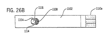
本発明の好ましい実施態様を詳細に説明する。図1を参照すると、血液抜き取りデバイス10はハウジング12を含む。ハウジング12内には真空ポンプ14、切開アセンブリ16、バッテリ18及び電子機器20が配置されている。スイッチ22が電子機器20を動作状態にするために設けられている。
Preferred embodiments of the present invention will be described in detail. Referring to FIG. 1, the
ハウジング12はプラスチック材料から製造されるのが好ましい。ハウジング12は好ましくは、血液サンプルを抜き取る皮膚面に非閉塞開口を形成し、皮膚の非閉塞開口から血液サンプルを好ましくは真空及び皮膚伸張を用いて抜き取り、抜き取ったサンプルを診断テストを実施するのに十分な量回収するのに必要な構成部分を全て収容するのに十分な大きさを有している。ハウジング12を作成する方法は当業者に公知である。上記したように、ハウジング12は必須ではないが、患者の都合及び構成部分の保護のために好ましい。
The
真空ポンプ14は、血液サンプルを抜き取る領域の皮膚部分を伸張させるに十分な吸引を与える真空を与え得るものでなければならない。通常、伸張した皮膚部分は該部分を含む身体の面から1〜10mm、好ましくは3〜5mmの距離持ち上げられる。真空ポンプ14による吸引により皮膚の適当な部分が伸張されるので、真空ポンプ14による吸引により伸張した部分が充血するようにもなる。与えられる真空レベルは、真空を適用したポイントが比較的多量の血液で充満されるようになるに十分でなければならない。真空ポンプ14はまた、5分以内に少なくとも1μlの血液を抜き取るのに十分な速度で皮膚の開口から血液を抜き取るのに十分な吸引を与え得るものでなければならない。本発明のデバイスに適した真空ポンプ14は隔膜ポンプ、ピストンポンプ、ロータリーベーンポンプ、または上記した所要機能を実行する他のポンプであり得る。通常、真空ポンプ14は内蔵永久磁石付きDCモータを使用する。本発明のために適した真空ポンプは当業者に公知であり、市販されている。本発明での使用に好適な真空ポンプはニュージャージー州ナットリーに所在のT−Squared Manufacturing Companyから市販されており、部品番号T2−03.08.004を有する。
The
真空ポンプ14は約−14.7psigまでの圧力を与ええるものが好ましく、より好ましくは約−3.0psig〜約−10.0psigで作動させる。真空とする皮膚の面積は好ましく最大約50cm2、より好ましくは約0.1〜約5.0cm2である。皮膚に開口を形成する前に、すなわち真空適用部位に対する血液のアベイラビリティーを高めるために真空を適用する時間は、好ましくは最長約5分、より好ましくは約1〜約15秒である。皮膚に開口を形成した後、すなわち非閉塞開口からの血液の抜き取りを補助するために真空を適用する時間は、好ましくは最長5分、より好ましくは約1〜約60秒である。真空ポンプ14により与えられる真空は連続式であってもパルス式であってもよい。連続真空が好ましい。なぜならば、パルス式真空に比して構成部分が少なくと済むからである。適用される真空が皮膚に対して回復不能なダメージを与えないことが好ましい。適用される真空が皮膚に数日間も続く挫傷や変色を生じさせないことが好ましい。適用される真空のレベル及び真空の適用期間が真皮が表皮から剥がれて流体が詰まった水泡が形成されるほど過度でないことも好ましい。
Preferably,
真空ポンプの要件は、予め減圧状態にある密封真空チャンバを用いる米国特許第5,320,607号明細書に記載されている方法及び装置に比して顕著な利点を与える。真空ポンプを用いると、使用者は予め減圧状態にある密封真空チャンバを用いたときに比して血液抜き取り条件をうまくコントロールできる。例えば、真空が不十分な場合にはエネルギーを真空ポンプに加えてより高レベルの真空を得ることができ、これによりより大きい吸引が得られる。 The requirement for a vacuum pump offers significant advantages over the method and apparatus described in U.S. Pat. No. 5,320,607 which utilizes a pre-evacuated sealed vacuum chamber. The use of a vacuum pump allows the user to better control the blood draw conditions as compared to using a sealed vacuum chamber that is pre-pressurized. For example, if the vacuum is inadequate, energy can be applied to the vacuum pump to obtain a higher level of vacuum, which results in greater suction.
切開アセンブリ16は少なくとも1つのランセットを含む。一般的なランセットを本発明の切開アセンブリに使用することができる。小ゲージ(28〜30ゲージ)のランセットが好ましい。本発明のために好適なランセットは金属またはプラスチックから製造され得る。本発明のために好適なランセットは単一ポイントまたは多ポイントを有し得る。ランセットの穿通深さは好ましくは約0.4〜約2.5mm、より好ましくは約0.4〜約1.6mmである。ランセットの長さは好ましくは約1mm〜約5mmである。切開アセンブリは使用者が使用済みランセットを簡単に取替え得るように配置されるものが好ましい。切開アセンブリ16のランセットは、手動により、または例えば真空作動式ピストンまたは隔膜を用いて自動的に発射準備され得る。切開アセンブリ16のランセットは、手動により、または例えば真空作動式ピストンまたは隔膜を用いて自動的に発射され得る。
切開アセンブリは当業界で公知である。本発明のために適当な切開アセンブリの代表例は、援用により本明細書に含まれるとする米国再発行特許第32,922号明細書、米国特許第4,203,446号明細書、同第4,990,154号明細書及び同5,487,748号明細書に記載されている。本発明のために特に好適な切開アセンブリは米国再発行特許第32,922号明細書に記載されている。いずれにせよ、切開アセンブリは本発明の装置の他の要件と一緒になって作動するものを選択しなければならない。例えば、真空を用いる場合、真空が形成され、アセンブリから引き抜かれ得るように切開アセンブリを設計しなければならない。切開アセンブリは、ランセットが自動的に発射準備され、自動的に発射され得るように設計され得る。 Incision assemblies are known in the art. Representative examples of lancing assemblies suitable for the present invention are U.S. Pat. Nos. Re. 32,922; U.S. Pat. Nos. 4,203,446; Nos. 4,990,154 and 5,487,748. A particularly suitable lancing assembly for the present invention is described in U.S. Pat. No. Re. 32,922. In any case, the lancing assembly must be chosen to work in conjunction with the other requirements of the device of the present invention. For example, if a vacuum is used, the lancing assembly must be designed so that a vacuum can be created and withdrawn from the assembly. The lancing assembly can be designed such that the lancet can be automatically primed and fired automatically.
一般的な切開アセンブリが本発明での使用に適しているが、ランセットを皮膚組織に押出すために差ガス圧を用いる切開アセンブリが本発明での使用のために開発された。本明細書中、「差ガス圧」は高圧ガス源(例えば、大気空気または加圧空気)と低圧ガス源(例えば、真空内の空気)とのガス圧の差を意味する。いずれにせよ、高圧下のガス源の圧力は低圧下のガス源の圧力を越える。 While general lancing assemblies are suitable for use with the present invention, lancing assemblies that use differential gas pressure to extrude a lancet into skin tissue have been developed for use with the present invention. As used herein, "differential gas pressure" refers to the difference in gas pressure between a high pressure gas source (eg, atmospheric air or pressurized air) and a low pressure gas source (eg, air in a vacuum). In any case, the pressure of the gas source under high pressure exceeds the pressure of the gas source under low pressure.
図11、12、13及び14に本発明での使用に好適な切開アセンブリの実施態様を示す。この実施態様においてガスは空気であるが、空気の代わりに他のガス、たとえば窒素、炭酸ガスを低圧下のガス源及び/または高圧下のガス源として使用することができることも注目すべきである。この実施態様の切開アセンブリ60はハウジング62、ランセットホルダ66を有するピストン64、ボデー67bに挿入されるランセット67aを含むランセットアセンブリ67、ピストンバイアス手段68(この実施態様では戻りばねである)及びキャップ70を含む。ハウジング62は三方弁74が嵌合され得るマニホールド72を有している。三方弁74をマニホールド72に配置する方法については図13及び14を参照されたい。三方弁74により、ハウジング62の外部の源からの空気は入口ポート76を介してボアポート78を選択的に通過し、こうしてボア80内の圧力が高められる。ボア80内の圧力が高くなると、ピストン64は標的皮膚組織に対して押出されると同時に戻りばね68を圧縮する。ピストン64はキャップ70またはランセット67aの皮膚内への穿通深さを制限すべく設計された別の構造物により停止している。前記した他の構造物は後記するテストストリップの形態のグルコース検出器または図2に図番39で示すようなランセットストップであり得る。次いで、三方弁74により、ボア80内の空気は出口ポート82を介して低圧空気の源、例えば装置内の排出空気キャビティに流れ、これによりボア80内の圧力レベルは低下し、その結果として戻りばね68によりピストン64はボア60の押出し前の位置に戻る。
FIGS. 11, 12, 13 and 14 show embodiments of a lancing assembly suitable for use with the present invention. In this embodiment, the gas is air, but it should also be noted that instead of air, other gases, such as nitrogen, carbon dioxide, can be used as a gas source under low pressure and / or a gas source under high pressure. . The lancing
構成部分は、以下に更に説明するように装置の寸法制限及び切開方法の性能要件の両方を満たすために適正なサイズを有していなければならない。本発明の切開アセンブリでは従来のばね式デバイスに比して占めるスペースが少なくて済み、通常ランセットの移動距離が短くて済む。 The components must be of the correct size to meet both the dimensional limitations of the device and the performance requirements of the lancing method, as described further below. The lancing assembly of the present invention occupies less space compared to conventional spring-loaded devices and typically requires less travel for the lancet.
ボア80は通常円筒形のチャンバであり、チャンバ内ではピストン64を標的皮膚組織に押出すための差空気圧が生ずる。ボア80はまた、oリング84に対して低摩擦空気シールを形成しながらピストン64を標的皮膚部位に案内すべく機能する。oリング84は切開作業中高圧空気がボア80から漏れるのを防ぐために望ましい。なぜならば、高圧空気が漏れるとボア80内の空気圧レベルが下がり、その結果ピストン64の押出しスピードが遅くなるからである。マニホールド72は、空気をボア80にまたはボア80から流すべくボアポート78を入口ポート76または出口ポート82に選択的に接続する三方弁74を嵌合するように形成される。出口ポート82は通常低圧空気源に配管されている。入口ポート76は通常低圧空気源よりも高圧の空気源に配管されている。ポート76、78及び82は三方弁74の対応するポートに連通するように配置されており、好ましくは流れ抵抗が三方弁74のポートよりも少なくなるような寸法を有する。
ピストン64は切開アセンブリ60の可動性構成部分である。ピストン64は好ましくは円筒形であり、ランセットホルダ66と標準oリングの外周グランド83を有する。ランセットホルダ66は、使用者が従来の切開デバイスと同様に挿入する使い捨てランセットアセンブリ67を固定的に載置するように設計される。ランセットアセンブリ67はランセット67aを含み、このランセット67aは成形プラスチックボデー67bに挿入される。oリング84は切開中ボア80内の空気圧を維持するためのシールとして機能する。oリングはボア80に沿って無視できる程度のすべり摩擦力しか生ずるべきではない(ピストン64に対して作用する圧力に比して無視できる)。ピストン64の軸64aの長さは所望のストローク距離、通常5mm〜25mmを与えるように選択される。ピストン64の上面64bの外径は円筒形ピストンの直径で通常5mm〜10mmであるが、圧力がピストン64及びランセットアセンブリ67を押出すのに十分な表面積を与えるように選択される。
戻りばね68は通常金属コイルばねであり、ピストン64とキャップ70の間で圧縮される。ばね68は、ボア80内の差空気圧が実質的にゼロの場合にはピストン64をボア80内のその最大深さまで押しやる。この作用によりピストン64は適所に配置され、切開過程が開始する。このピストン64の位置は、装置を標的皮膚組織に対して置いたときにピストン64が標的皮膚組織から更も遠く離れる位置である。ばね68はまた、切開過程の終了時にランセットホルダ66中のランセットアセンブリ67を標的皮膚組織から引込める。ばね力はピストン/ランセットシステムの重量とoリング84の滑り摩擦に打ち勝つに十分でなければならない。
キャップ70はハウジング62内に固定的に配置される。キャップ70は、戻りばね68が自由に圧縮するに十分な半径隙間を与えると共に戻りばね68を適切に配置する。キャップ
70は、ランセットホルダ66が移動できる通路88を有する。
キャップ70はまた、ピストン64を標的皮膚組織に対して案内するのを助けるように機能する。
The
図15A、15B及び15Cに、図11及び12の切開アセンブリを仮想装置91内に据え付けた例を示す。切開アセンブリ60は装置91のキャビティ92内に固定され、三方ソレノイド弁74及び標準的な使い捨てランセットアセンブリ93が図示するように取付けられている。ランセットアセンブリ93はランセット93aを含み、このランセット93aは成形プラスチックボデー93b内に挿入される。装置91は下部通路94を有しており、ランセットアセンブリ93はこの通路94を通過して移動して、下部通路の円形開口部94a(点線で示す)で取り囲まれる皮膚“S”面に非閉塞開口を形成することができる。装置91の側壁96にある側部ポート95を介して、切開アセンブリ60の入口ポート76は装置91の周りの大気空気と接続している。装置91はまた、キャビティ92内の空気圧を装置が作動するレベルに維持するために真空源97及び三方ソレノイド弁74を選択的に動作状態にするための電圧源98を有している。電圧をオフにすると、三方ソレノイド弁74は切開アセンブリ60のボア80を出口ポート82を介してキャビティ92に接続し、ピストン64は差空気圧を受けなくなる。
FIGS. 15A, 15B and 15C show examples in which the dissection assembly of FIGS. 11 and 12 is installed in the
準備モード(図15A)では、装置91の下部通路94は標的皮膚を横切って置く。装置の真空圧を、実質的に大気圧力Pa未満である操作レベルPvとする(例えば、Pv=−7.5psig、Pa=0psig)。真空圧Pvにより標的皮膚は下部通路94に少し引き寄せられる。三方ソレノイド弁74の電圧は最初オフであり、これにより大気空気が切開アセンブリ60に進入するのが防止され、戻りばね68によりランセット93aを皮膚から最長距離(例えば、10mm)に維持し得る。
In the preparation mode (FIG. 15A), the
切開モード(図15B)では、三方ソレノイド弁74を電圧源98により動作状態にし、よって大気空気が連続的に装置91の側部ポート95、入口ポート76、次いでボアポート78を介して切開アセンブリ60のボア80に流れる。大気空気流によりボア80内の空気圧が上昇し、よって差空気圧がピストン64に作用する。ピストン64に対して作用する差空気圧は急速に上昇し、戻りばね68の対抗圧及びoリングの摩擦に打ち勝ち、よってピストン64とランセットアセンブリ93の合計質量(例えば、1.5g)が標的皮膚を押出す。ランセット93aは短時間(例えば、6msec)皮膚と接触し、十分な速度(例えば、3.5m/sec)で進んで皮膚に開口を形成し、特定深さ(例えば、1.5mm)まで穿通する。ランセットアセンブリ93の押出し運動が幾つかの停止手段により停止したときに皮膚の開口は完成する。ランセットアセンブリ93を停止させるための適当な手段には、事実上ピストン64のストローク距離を制限する切開アセンブリ60内のキャップ70及び図20に記載するようなランセットストップが含まれるが、これらに限定されない。
In the lancing mode (FIG. 15B), the three-
戻りモード(図15C)では、所定滞留時間(例えば、10msec)後ソレノイドの電圧が遮断されるとランセット93aは皮膚から引込められる。電圧がオフになると、三方ソレノイド弁74によりボア80はボアポート78を介して切開アセンブリ60の出口ポート82に再接続し、よってボア80からの空気は三方ソレノイド弁74により出口ポート82を介して、真空源97により装置内に与えられる低圧空気を含んでいるキャビティ92に非常に迅速に(例えば、15msec)排気される。排気中、圧縮された戻りばね68は差空気圧とoリング84の摩擦との総合力に打ち勝ち、ピストン64及びランセットアセンブリ93をスタート位置に戻す。こうして、この仮想装置において全部で25msec要する切開サイクルが完了する。
In the return mode (FIG. 15C), when the voltage of the solenoid is cut off after a predetermined residence time (for example, 10 msec), the
ソレノイドは装置の電圧システムにより駆動する。電圧がオンになり、その後オフになる度毎に(すなわち、1パルス)、三方ソレノイド弁74は内部で切換わり、まず空気流を切開アセンブリ60に流入、その後切開アセンブリ60から流出させる。この切換により、ランセットを標的皮膚組織に押出し、その後標的皮膚組織から引込める。ソレノイドを電圧で繰り返し間欠的に作動させることにより、切開方法が反復される。この要件を「反復切開」と称する。
The solenoid is driven by the voltage system of the device. Each time the voltage is turned on and then turned off (i.e., one pulse), the three-
こうして皮膚に形成された開口は慣用の切開デバイスで形成されるものと同じである。前記開口により、分析用に生物学的流体(例えば、約3μlの毛細血)をサンプリグすることができる。 The opening thus formed in the skin is the same as that formed with a conventional lancing device. The aperture allows for sampling of a biological fluid (eg, about 3 μl of capillary blood) for analysis.
図15A、15B及び15Cに示す切開方法は、同じランセットを用い、デバイスまたは標的皮膚を妨害することなく所望の回数反復させることができる。皮膚を真空吸引により適所に保持しながら、標的面を1回以上切開するために必要なだけソレノイド電圧をパルスすることができる。切開を反復することには2つの有力な利点がある。第1は、生物学的流体に更に近づくべく標的皮膚上に部位のマトリックスを切開するために装置中の指示システムと協同することができる。第2に、所望の量の血液が得られるまで皮膚を順次切開することにより1つの部位もしくはその近くでの切開成功率を高めることができる。 The dissection method shown in FIGS. 15A, 15B and 15C can be repeated the desired number of times without disturbing the device or target skin using the same lancet. While holding the skin in place by vacuum suction, the solenoid voltage can be pulsed as needed to make one or more incisions in the target surface. Repeating the incision has two potential advantages. First, it can cooperate with an indicating system in the device to cut the matrix of the site on the target skin to get closer to the biological fluid. Second, the success rate of incision at or near one site can be increased by sequentially incising the skin until a desired amount of blood is obtained.
図16及び17に、切開アセンブリの別の実施態様を示す。これらの図面において、プライム符号付き図番(すなわち、図番60’、62’、64’、64a’、64b’、66’、70’、72’、76’、78’、80’、82’、88’)は、図11及び12のプライム符号は付いていないが同じ図番(すなわち、図番60、62、64、66、70、72、76、78、80、82、88)で示す構成部分と同一か少なくとも実質的に同一の構成部分を示す。図16及び17において、典型的には円筒形成形エラストマーであるベローズ89は、ボア80’に対する気密シールとして、またピストン64’をバイアスするための手段として機能する。ベローズ89は、図11及び12のoリング84及び戻りばね68の代替部分として有効である。ベローズ89を収容するために、ピストン64’の軸64a’はボア80’よりも十分に小さい半径方向断面寸法を有し、ベローズ89に対して十分なクリアランスを与えるものでなければならない。プレート90は、ベローズ89をピストン64’の軸64a’に固定且つシールし、ピストン64’をボア80’中案内する手段を提供する。キャップ70’及びハウジング62’は図示するようにベローズ89の下部を固定且つシールするように成形される。この実施態様は、図11、12、13、14、15A、15B及び15Cに示す実施態様と同様に使用され得る。ベローズ89を用いる実施態様によれば、oリング84を用いる実施態様に比較して滑り摩擦が減るという有力な利点が得られることは明白である。ベローズはoリングのようにボア表面を擦ることがないので、ベローズの摩擦力を低くし得る。摩擦力はピストンのスピードを遅らすという望ましくない影響を有する。また、ベローズではボア80’に収容するための寸法公差が、oリング84をボア80に収容するために必要な寸法公差よりも少なくて済むことも明白である。ベローズは、oリングのようにボアに正確に嵌合させる必要はない。ボアがoリングの周りにぴったりと嵌合していると、過度の滑り摩擦が生ずることがある。ボアがoリングの周りにゆるく嵌合していると、空気が過度に漏れることがある。ベローズをoリングの適所に使用することにより、ボアの製造公差が緩和され、その結果製造コストが低下し、少数の部品が不要となる。ベローズ89は、(1)シールとして作用する、(2)圧力下での半径方向破壊に耐える、(3)切開アセンブリを押出しステップ後当初の押出し前位置に引込める、及び(4)操作中差ガス圧に打ち勝つ力を有するという機能を発揮することができるように十分な剛性と十分な可撓性を有する材料から製造されるのが好ましい。
16 and 17 show another embodiment of the lancing assembly. In these figures, primed figure numbers (i.e.,
図18及び19に、切開アセンブリの別の実施態様を示す。これらの図面において、二重プライム符号付き図番(すなわち、図番60”、62”、64”、64a”、64b”、66”、68”、70”、72”、76”、78”、80”、82”、88”)は、図11及び12のプライム符号は付いていないが同じ図番(すなわち、図番60、62、64、66、68、70、72、76、78、80、82、88)で示す構成部分と同一か少なくとも実質的に同一の構成部分を示す。図18及び19において、典型的には成形エラストマーである隔膜84aは、ボア80”に対する気密シールとして機能する。実際、隔膜84は図11及び12のoリングの代替部分である。隔膜84aはハウジング62”及びピストン64”の軸64a”に固定され、ピストン64”の軸64a”がボア80”内を軸方向に移動するときボア80”内で屈曲し得る。隔膜84aを収容するために、ピストン64”の軸64a”は、隔膜84aに対して十分なクリアランスを与えるためにボア80”よりも十分に小さい半径方向断面寸法を有していなければならない。更に、ハウジング62”及びハウジングの頂部62a”は、隔膜84aが据え付けられ得るアセンブリ要件を有していなければならない。アセンブリ要件とはハウジング62”とハウジングの頂部62a” との間の隔膜84aを効果的にシールしなければならないことである。好ましくは、隔膜84aは固定具83aによりピストン64”の軸64a”に固定される。この実施態様は図11〜17に示す実施態様と同様に使用され得る。隔膜84aは、(1)シールとして作用する、(2)切開アセンブリの操作中圧力下での破壊に耐える、(3)切開アセンブリによりランセットを患者の皮膚に押出すことができる、及び(4)切開アセンブリを押出しステップ後当初の押出し前位置に引込めることができるという機能を発揮するために十分な強度と十分な可撓性を有する材料から製造されるのが好ましい。
18 and 19 show another embodiment of the lancing assembly. In these figures, double primed figure numbers (ie,
図11〜19の切開アセンブリの構成部分は、該切開アセンブリに有効な寸法エンベロープに一致する形状及びサイズを有していなければならない。構成部分の適正なデザインも、皮膚の切開に関し許容できる結果を得るために重要な要因である。他の重要な要因は、下記するように三方弁の性能(すなわち、弁の流れ抵抗及び切換時間)及び切開アセンブリを操作する空気圧環境である。切開アセンブリを構成する部分は市販されており、当業者ならば市販されているものの中から適当な構成部分を選択する能力を十分備えているものと予想される。 The components of the lancing assembly of FIGS. 11-19 must have a shape and size consistent with the dimensional envelope available for the lancing assembly. Proper design of the components is also an important factor in obtaining acceptable results for skin incision. Other important factors are the performance of the three-way valve (ie, valve flow resistance and switching time) and the pneumatic environment operating the lancing assembly, as described below. The components that make up the lancing assembly are commercially available and those skilled in the art are expected to have sufficient ability to select appropriate components from those that are commercially available.
切開結果は3つの主要パラメータにより影響されると考えられる:(1)皮膚と衝突中のランセットスピード;(2)切開アセンブリのランセット/ピストンの慣性質量;及び(3)ランセットニードルの形態及び大きさ。第3のパラメータは本発明の切開アセンブリでは当てはまらない。なぜならば、前記切開アセンブリは最も一般的なランセットアセンブリ、例えば“BD ULTRA−FINE”(Becton−Dickinson)ブランド及び“ULTRATLC”(MediSense)ブランドを使って機能すると予想されるからである。ランセットスピード及び慣性質量の切開性能に対する正確な影響は十分に理解されていないが、第1及び第2のパラメータは切開アセンブリ中の構成部分の幾何学的形状及び重量により大きく影響される。しかしながら、通常1.0g〜2.0gの慣性質量を有し、3m/sec〜5m/secのピークランセットスピードを出す慣用のデバイスで良好な切開性能が認められた。 Incision results are believed to be affected by three key parameters: (1) lancet speed during collision with the skin; (2) lancet / piston inertial mass of the incision assembly; and (3) lancet needle shape and size. . The third parameter does not apply in the lancing assembly of the present invention. This is because the lancing assembly is expected to function using the most common lancet assemblies, for example, the "BD ULTRA-FINE" (Becton-Dickinson) brand and the "ULTRATLC" (MediaSense) brand. Although the exact effects of lancet speed and proof mass on cutting performance are not well understood, the first and second parameters are greatly affected by the geometry and weight of the components in the cutting assembly. However, good incision performance was observed with a conventional device that usually has an inertial mass of 1.0 g to 2.0 g and provides a peak lancet speed of 3 m / sec to 5 m / sec.
ランセットスピードを切開アセンブリのデザイン及び圧力環境に関連づける一般的な数式は、以下のように物理法則から公式化され得る。
M×a(t)=A×[Pc(t)−Pv(t)]−Ks×[x(t)+Xs]−Ff(t)
上記式中、
t=経過時間
M=総慣性質量(ピストン+切開アセンブリ)
a(t)=時間tにおけるランセットの並進加速度
Pc(t)=時間tにおいてピストンの上面に作用する空気圧
Pv(t)=時間tにおいてピストンの作用に対抗する空気圧
A=Pc(t)及びPv(t)による作用を受けるピストンの投影表面積
Ks=戻りばねのばね定数
x(t)=時間tにおけるランセットの並進変位
Xs=戻りばねの初期変位
Ff(t)=時間tにおけるピストンシールの摩擦力
Pc(t)−Pv(t)=時間tにおいてピストンを加速させる差圧力レベル
ランセット変位(X)対時間(t)に関する上記数式から経時的ランセットスピードが求められ得るが、上記数式の解決には本発明の設計の詳細及び三方弁を含む熱力学及び圧縮流の分野における多くの補助方程式を必要とする。一般的に、皮膚に衝突時のランセットスピード(Up)は下記の変数で表され得る。
Up=F[A,M,S,Xp,Ks,Xs,Cv,Dtv,Vc,Vv,Pa,Pv,Ta,Ff]
上記式中、
A=空気圧が作用するピストンの有効表面積
M=総慣性質量(ピストン+ランセットアセンブリ)
S=ピストンのストローク距離
Xp=皮膚と衝突が起きたときのランセット変位(Xp<S)
Ks=戻りばねのばね定数
Xs=戻りばねの初期変位
Cv=動作状態にした三方弁の流量係数
Dtv=三方弁の切換時間(完全に動作状態にするための時間)
Vc=ピストンと三方弁間の初期空気容積
Vv=装置の初期キャビティ容積(すなわち、ランセットを作動させる前に測定したキャビティの容積)
Pa=高圧空気源の圧力レベル
Pv=装置のキャビティの初期圧力レベル(すなわち、ランセットを作動させる前に測定した低圧空気源の圧力)
Ta=空気温度レベル
Ff=ピストンシールの摩擦力プロフィール(通常、ピストンの変位に応じて変化する)
ピストンの特定ストローク距離(S)内のランセットスピードの最大化は、高流量係数(Cv)及び迅速切換時間(Dtv)を有する三方弁を選択することにより、ピストンの表面積(A)及びピストンと三方弁間の初期空気容積(Vc)を最適化することにより、総慣性質量(M)、ばね力(Ks,Xs)及びピストンシールの摩擦力プロフィール(Ff)を最小化することにより、十分な初期キャビティ容積(Vv)を確保することにより、また装置が許す限り大きい差圧(Pa−Pv)を適用することにより達成される。
A general formula relating lancet speed to the design of the lancing assembly and the pressure environment can be formulated from physical laws as follows.
M × a (t) = A × [P c (t) -P v (t)] - K s × [x (t) + X s] -Ff (t)
In the above formula,
t = elapsed time M = total inertial mass (piston + incision assembly)
a (t) = translational acceleration of the lancet at time t Pc (t) = air pressure Pv (t) acting on the upper surface of the piston at time t = air pressure A = Pc (t against the action of the piston at time t ) And P v (t) the projected surface area of the piston K s = spring constant of the return spring x (t) = translational displacement of the lancet at time t X s = initial displacement of the return spring Ff (t) = time t time lancet speed from the equation may be asked about the frictional force of the piston seal P c (t) -P v (t) = time difference pressure level lancet displacement to accelerate the piston in the t (X) versus time (t) in However, solving the above equations requires design details of the present invention and many auxiliary equations in the field of thermodynamics and compressed flow, including three-way valves. Typically, the lancet speed at the time of collision to the skin (U p) can be expressed by the following variables.
U p = F [A, M , S, X p, K s, X s, C v, Dt v, V c, V v, P a, P v, T a, Ff]
In the above formula,
A = effective surface area of piston on which air pressure acts M = total inertial mass (piston + lancet assembly)
S = stroke distance of piston X p = lancet displacement when collision with skin occurs (X p <S)
K s = spring constant of the return spring X s = initial displacement of the return spring C v = flow coefficient Dt v of the three-way valve in operation state = switching time of the three-way valve (time for fully operating state)
V c = initial air volume between piston and three-way valve V v = initial cavity volume of device (ie, volume of cavity measured before actuation of lancet)
P a = pressure level of high pressure air source P v = initial pressure level of device cavity (ie pressure of low pressure air source measured before actuation of lancet)
T a = air temperature level Ff = frictional force profile of piston seal (typically varies with piston displacement)
Maximizing the lancet speed within a specific stroke distance (S) of the piston is achieved by selecting a three-way valve having a high flow coefficient (C v ) and a quick switching time (Dt v ) by increasing the piston surface area (A) and piston If by optimizing the initial air volume (V c) between the three-way valve, the total inertial mass (M), the spring force (K s, X s) and to minimize the frictional force profile a (Ff) of the piston seal Accordingly, by ensuring sufficient initial cavity volume (V v), also is achieved by applying a large pressure difference as the equipment will permit (P a -P v).
差ガス圧を用いる切開アセンブリは従来の切開アセンブリに比して幾つかの利点を有する。これらの利点は、ランセットを皮膚に押出すために圧縮ばねを用いたことよりもむしろ差ガス圧を用いることによりもたらされる。1つの利点は、使用する前に使用者がランセットを手で発射準備する必要がない。これにより、使用が簡便となり、より多くの血液を入手するために標的皮膚を順次切開することができる。差ガス圧を与えるガスが使用後切開アセンブリから排気され、これによりピストンバイアス手段によりランセットを元の位置に戻すことができるので発射準備は不要である。別の利点は、切開アセンブリを機械的に発射する必要がないことである。これにより、デバイスの設計が単純になり、デバイスの操作を誤ったとき使用者による偶発的な発射を防止する。差ガス圧が切開過程を開始し、実行するように機能するので別の発射機構は不要である。更に別の利点は、切開が進行しなくなったとき切開アセンブリがランセットを完全に引込めることである。これにより、使用のための準備中または使用後にデバイスを取り扱う際使用者が鋭いランセットに触れることが最小限に抑えられる。ランセットの完全引込みは、差ガス圧を与えるガスが既に切開アセンブリから排気された後にピストンバイアス手段により達成される。 Dissection assemblies using differential gas pressure have several advantages over conventional dissection assemblies. These advantages are provided by using differential gas pressure rather than using a compression spring to push the lancet into the skin. One advantage is that the user does not have to manually prime the lancet before use. This simplifies use and allows for successive incisions in the target skin to obtain more blood. No preparation is required since the gas providing the differential gas pressure is evacuated from the lancing assembly after use, so that the lancet can be returned to its original position by the piston biasing means. Another advantage is that there is no need to fire the lancing assembly mechanically. This simplifies the design of the device and prevents accidental firing by the user when erroneously operating the device. No separate firing mechanism is required as the differential gas pressure functions to initiate and perform the lancing process. Yet another advantage is that the lancing assembly can completely retract the lancet when the lancing no longer proceeds. This minimizes the user from touching the sharp lancet when handling the device during or after preparation for use. Full retraction of the lancet is achieved by the piston biasing means after the gas providing the differential gas pressure has already been exhausted from the lancing assembly.
図1に戻ると、真空ポンプ14は排気管24により切開アセンブリ16に接続されている。真空ポンプ14により切開アセンブリ16から排気された空気は、排気管24を介して除去される。排気管24は通常ポリマー材料から製造される。真空ポンプ14により切開アセンブリ16から除去された空気が切開アセンブリ16に逆流するのを防止し、真空への悪影響を防止するために、チェック弁26が真空ポンプ14と切開アセンブリ16の間の排気管24の任意の地点に設置されている。
Returning to FIG. 1, the
真空ポンプ14のためのパワー源はハウジング12内に配置され得る。本発明のデバイスに適したパワー源はバッテリ18である。或いは、外部パワー源を真空ポンプ14を作動させるために使用することができる。パワー源は電子機器20により作動し、また電子機器20はスイッチ22により作動する。
A power source for
電子機器20にマイクロプロセッサまたはマイクロコントローラを組み入れてもよい。電子機器20の機能は、装置中の各種構成成分を操作するためにパワーをオン/オフに切換えることである。前記構成成分には真空ポンプ14が含まれるが、これに限定されない。電子機器20はまた、別の実施態様の構成成分、例えば加熱素子、ランセット、指示デバイス及び弁を操作するためにパワーをオン/オフに切換えるために使用することができる。本発明のために好適な電子機器は、536 MacArthur Blvd.P.O.Box 3450,ポカセット,マサチューセッツ州 02559−3450に所在のOnset Computer Corporationから市販されている“TATTLETALE MODEL 5F”コントローラ/データロガーである。コントローラと演算成分との間にインターフェースを提供するためにパワートランジスタ、圧力モニター及びOP−Amps(演算増幅器)のような補助電子デバイスが必要な場合もある。本発明のために必要な電子機器はすべて当業者に公知であり、市販されている。本発明で使用するのに適した補助電子デバイスには、下表の構成成分が含まれる。
The
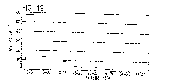
図3に、本発明の方法を実施するために上記電子構成部分がどのように配置され得るかをブロック図で示す。 FIG. 3 shows in a block diagram how the electronic components can be arranged to carry out the method of the invention.
血液抜き取りデバイス10の操作を以下に記載する。図1、2及び3を参照すると、切開アセンブリ16のノーズピース30を図中“S”で示す皮膚表面に当てる。皮膚と接触するノーズピース30の端部にはシール32が備えられている。シール32の目的は、真空ポンプ14がサンプルを抜き取る皮膚面への血液のアベイラビリティーを高め、皮膚を伸張し、皮膚の非閉塞開口から血液サンプルを抜き取るのに十分な吸引作用を与え得るように空気が血液抜き取りチャンバ34中に漏れるのを防ぐことである。シール32はノーズピース30の開口部33を包囲している。ノーズピースの開口部33を介して、皮膚表面とノーズピース30の血液抜き取りチャンバ34とは連通している。シール32はゴムまたはエラストマー材料から製造されるのが好ましい。図4に、シール32の代替位置を示す。図4では、シールを図番32’で示す。図4の残りの構成部分は図2の構成部分と同一であるので、図2に用いたのと同じ図番を用いる。
The operation of the
ノーズピース30のデザイン及び構造を改良すると、皮膚の非閉塞開口からの血液の回収量を増やすことができることが判明した。図2では、ノーズピースの内壁が本質的に円筒形の形状を形成している。このデザインでも本発明の方法は十分な性能を発揮し得るが、ノーズピースの内部キャビティの構造を変更することにより血液の回収を促進し得ることが判明した。
It has been found that improving the design and structure of the
ノーズピースアセンブリ3000を図32に示す。ノーズピースアセンブリ3000はノーズピース3001及びシール3002を含む。ノーズピース3001は、開口部3005を有する下部ベース3004を含む。下部ベース3004上に、開口部3007を有する上部ベース3006がある。下部ベース3004及び上部ベース3006以外のノーズピースの外側の要件は本発明では重要でなく、当業者ならば本発明のノーズピースの操作に悪影響を与えないようにノーズピースの外壁を設計することができる。ノーズピースの内側要件、下部ベース3004、上部ベース3006及び場合によりシール3002が重要であり、よってこれらについて詳細に記載する。内壁3008はノーズピース3001のキャビテイ3010を包囲している。上部ベース3006の開口部3007の面積が下部ベース3004の開口部3005と等しいかもしくはそれよりも小さくなるようにノーズピース3001の内壁3008を構成することが重要である。開口部3007の面積をできるだけ小さくすることが望ましいが、グルコースモニター(図2参照)による血液回収やランセットの通路を妨害するほど小さくてはならない。任意のリム3012で上部ベース3006の開口部3007を包囲することができる。
The
開口部3007の面積を開口部3005の面積よりも小さくするには幾つかの方法がある。図32に示すように、開口部3007の面積が小さくするように内壁3008をテーパー状にしし得る。テーパリングはノーズピース3001の内壁3008に沿った任意の地点から始めることができる。テーパー部分が該テーパー部分の始点から上部ベース3006までの範囲に及ぶならば、任意のリム3012の深さはゼロであり、よってノーズピースから除かれる。或いは、例えば段階的円筒断面を用いて開口部3007の面積を開口部3005の面積よりも小さくすることができる。
There are several methods for making the area of the
所要により、キャビテイ3010が真空により多く接するようにポート3014及び3016をノーズピース3001に含めることができる。
If desired,
ノーズピースアセンブリ3000の構造をより正確に記載するために、アルファベットで示す参照ポイントを図32に示し、これを用いて参照ポイント間の典型的な距離を記載することができる。任意のリム3012は線“ab”で示す深さを有する。この深さは通常0〜約1.5mm、好ましくは0〜約1.0mmである。上部ベース3006の開口部3007は線“cd”で示す外寸法を有する。開口部3007の面積は通常約1〜約500mm2、好ましくは約1〜約150mm2である。下部ベース3004の開口部3005は線“ef”で示す外寸法を有する。開口部3005の面積は通常約10〜約500mm2、好ましくは約50〜約150mm2である。リム3012の最低地点からシール3002の最低地点までの距離(以下、“リム−シール間距離”)は線“bg”で示す。この距離は通常約1.5〜約8.0mm、好ましくは約3〜約6mmである。ノーズピース3001に伸張されたときに皮膚がノーズピース3001のリム3012または上部ベース3006にできるだけ近づくように距離を選択することが好ましい。リム3012が存在しないときには、地点“d”は上部ベース3006の水平面に位置する。シール3002の厚みは線“eh”で示される。シールする表面の幅及び下部ベース3004のシールされる表面の幅は線“hj”で示される。当業者ならば過度の実験を行うことなく経験に基づいてノーズピースの寸法を最適化できるであろう。ノーズピース3001及びシール3002の詳細は実施例に記載する。
To more accurately describe the structure of the
上記した改良ノーズピースは幾つかの利点を有する。ノーズピースのデザイン及び構造を改良することにより皮膚の非閉塞開口から血液をより多く回収することができる。更に、上記ノーズピースを用いると、従来使用されているノーズピースよりも身体へのシールを改良することができる。シールが改良されると真空の漏出量が低減し、その結果より安価な真空ポンプを使用することができる。加えて、改良ノーズピースを用いると非常に毛深い皮膚を有するヒトでもシールを維持することができる。 The improved nosepiece described above has several advantages. Improved blood flow can be recovered from non-occlusive openings in the skin by improving the design and structure of the nosepiece. Further, the use of the nosepiece can improve the seal to the body as compared with the nosepiece conventionally used. Improved seals reduce the amount of vacuum leakage, so that less expensive vacuum pumps can be used. In addition, the improved nosepiece allows a person with very hairy skin to maintain a seal.
特に好ましいタイプのノーズピースは図42A及び42Bに断面を示すシール(以下、フレックスシールという)を有し得る。このフレックスシールはプレーナシールよりもより広い面積の皮膚に接触する。よって、フレックスシールにより、真空を適用したときにノーズピースの内部空間に入り込む皮膚の量がプレーナシールに比して多くなる。フレックスシールはシリコーン(40Aデュロメータ)から製造され得る。 A particularly preferred type of nosepiece may have a seal (hereinafter a flex seal) shown in cross-section in FIGS. 42A and 42B. The flex seal contacts a larger area of skin than the planar seal. Therefore, the amount of skin that enters the inner space of the nosepiece when a vacuum is applied is increased by the flex seal as compared with the planar seal. The flex seal may be manufactured from silicone (40A durometer).
フレックスシール3020は、機械的取付け具3024または接着剤によりノーズピース3022に結合され得る。ノーズピース3022に結合していないフレックスシールの部分3026は、図42Aに示す第1位置と図42Bに示す第2位置の間を移動し得る。図42Aに示すような第1位置では、フレックスシール3020の非結合部分3026はノーズピース3022の下部ベース3028から垂れ下がっている。図42Bに示すような第2位置では、フレックスシール3020の非結合部分3026は、シールの非結合部分の1つの外表面がノーズピースの下部ベース3028と面接触するようにノーズピース3022の下部ベース3028と接している。フレックスシールは、フレックスシールと接触する皮膚が滑る傾向を減らす摩擦係数を有する材料から製造される。シールは、第1位置と第2位置との間を移動することができるように十分な可撓性と皮膚を固定位置に保持するために十分な剛性を有していなければならない。フレックスシールが図42Aに示す第1位置にあるとき、フレックスシールの開口部3030の面積はノーズピース3022の下部ベース3028の開口部3032の面積より大きい。
操作時、フレックスシールを患者の皮膚“S”に対して置く。フレックスシールと接する皮膚の面積は、ノーズピースの下部ベースの開口部の面積よりも大きい。従って、ノーズピース内に持ち上げられる皮膚の容積は、プレーナシールを有するノーズピース内に持ち上げられた皮膚の容積に比して大きい。従って、フレックスシールは正常以下の皮膚柔軟性を有する患者にとって有利である。 In operation, the flex seal is placed against the patient's skin "S". The area of the skin in contact with the flex seal is larger than the area of the opening in the lower base of the nosepiece. Thus, the volume of skin lifted into the nosepiece is greater than the volume of skin lifted into the nosepiece having a planar seal. Therefore, flex seals are advantageous for patients with subnormal skin softness.
スイッチ22は通常押すことにより始動し、これにより電子機器22が動作状態になり、そして真空ポンプ14が動き始める。そして、真空ポンプ14が真空作用を与える。真空ポンプ14の吸引作用により、シール32で取り囲まれる皮膚は充血するようになる。皮膚を充血させるには、皮膚を開口部33まで伸張し、持ち上げる。
The
通常は電子機器のプログラマーにより予め設定される適当な時間経過後、切開アセンブリ16を発射し、これにより開口部33に持ち上げられ、充血している皮膚にランセット36を穿通させる。真空作動式ピストン(図示せず)によりランセット36を発射させるソレノイド弁38を用いてランセット36を自動的に発射させることが好ましい。次いで、ランセット36を、好ましくは自動的に引込める。この時点で、血液がランセット36と真空ポンプ14により生成される真空の補助で形成された非閉塞開口から流れ出、回収される。十分量の血液が回収されたとき、または予め設定した時間が経過したときに、電子機器20により真空ポンプ14を停止させる。その後、デバイス10の皮膚表面からの取り外しを容易にするために別のソレノイド弁(ソレノイド弁38の下に隠れているので図示されていない)を開いて真空を解放してから、デバイス10を皮膚表面から取り外すことができる。本明細書に記載の装置と一緒に使用するのに適したソレノイド弁はコネチカット州エセックスに所在のThe Lee Companyから市販されており、部品番号はLHDA511111Hである。
After an appropriate period of time, usually preset by the electronics programmer, the
血液をグルコース検出器の適用ゾーン、例えば反射率ストリップまたはバイオセンサーに直接回収することが好ましい。こうして回収した血液を血液中のグルコース濃度の測定用サンプルとして使用することができる。或いは、血液を別の回収デバイス、例えば毛細管または吸収紙を用いて回収してもよい。 It is preferred that the blood be collected directly on the application zone of the glucose detector, for example a reflectance strip or a biosensor. The blood thus collected can be used as a sample for measuring the glucose concentration in blood. Alternatively, the blood may be collected using another collection device, such as a capillary or absorbent paper.
本発明の装置は、装置により抜き取られた血液サンプルを分析するためにグルコース検出器を含むことができる。グルコース検出器は当業界で公知である。グルコース監視に関して、グルコース検出器は反射率計及びバイオセンサーの2つに大別される。本発明のために適している反射率計の代表例は、援用により明細書に含まれるとする米国特許第4,627,445号明細書に記載されている。本発明のために適しているバイオセンサーの代表例は、援用により明細書に含まれるとする米国特許第5,509,410号明細書に記載されている。 The device of the present invention can include a glucose detector to analyze a blood sample drawn by the device. Glucose detectors are known in the art. With respect to glucose monitoring, glucose detectors are broadly divided into reflectometers and biosensors. Representative examples of reflectometers suitable for the present invention are described in U.S. Pat. No. 4,627,445, which is incorporated herein by reference. Representative examples of biosensors suitable for the present invention are described in US Pat. No. 5,509,410, which is hereby incorporated by reference.
グルコース検出器を切開アセンブリ16のノーズピース30に配置するのが好ましい。グルコース検出器は、抜き取って回収される血液の量が標準のグルコース監視テストを実施するために十分であるように血液を抜き取る部位に十分に近い位置に設置しなければならない。通常、この距離が血液の抜き取り部位から5mm以下であることが好ましく、より好ましくは3mm以下、最も好ましくは1mm以下である。或いは、グルコース検出器を、ランセットを発射してからしばらくの間、好ましくは約50ミリ秒まで、ただしランセットを引込めるのに少なくとも十分な時間なら血液の抜き取り部位から5mm以上離してもよい。グルコース検出器をそのように設置すると、例えば真空作動式ピストンでグルコース検出器を発射させるソレノイド弁によりグルコース検出器が発射され得る。他の発射装置を使用してもよい。発射作用により、グルコース検出器は血液の抜き取り部位から好ましくは5mm以下、より好ましくは3mm以下、最も好ましくは1mm以下皮膚を進む。グルコース検出器を設置する場合、血液を抜き取る際に真空を適用するときにグルコース検出器が真空に悪影響を及ぼさないように注意しなければならない。また、グルコース検出器40は、必要によりグルコース検出器の回収ゾーンに回収された血液をグルコース検出器を動作状態にするために使用し得るように改変される。
Preferably, the glucose detector is located on the
図2に、グルコース検出器40を切開アセンブリ16のノーズピース30に配置する方法を示す。
FIG. 2 shows how the
本発明のグルコース検出器40の1実施態様は、
(a)血液を受容し、受容した血液を化学的ウィッキング(chemically aided wicking)により輸送し得る層、
(b)アナライトの存在を検出または血液中のアナライトの量を測定し得る層、及び
(c)血液輸送層の上にあり、メータに接して配置され得る層
を含む多層素子を含み、前記層(a)により血液は層(b)に輸送され得る。
One embodiment of the
(A) a layer capable of receiving blood and transporting the received blood by chemically aided wicking;
(B) a layer capable of detecting the presence of the analyte or measuring the amount of the analyte in the blood, and (c) a multilayer element comprising a layer overlying the blood transport layer and capable of being placed in contact with the meter; Said layer (a) allows blood to be transported to layer (b).
本発明のグルコース検出器40の1つの好ましい実施態様は、
(a)開口部を有する保護層、
(b)前記保護層の上にあり、血液を該保護層の開口部を介して受容し、血液を化学的ウィッキングにより輸送し得る層、
(c)前記血液輸送層の上にあり、メータに接して配置され得る層、及び
(d)前記保護層と前記メータ接触層との間に配置され、血液輸送層からの血液を受容し得る層であって、アナライトの存在を検出するかまたは血液中のアナライトの量を測定し得る層
を含む多層素子を含む。
One preferred embodiment of the
(A) a protective layer having an opening,
(B) a layer overlying the protective layer, capable of receiving blood through openings in the protective layer and transporting the blood by chemical wicking;
(C) a layer overlying the blood transport layer and capable of being disposed in contact with a meter; and (d) being disposed between the protective layer and the meter contact layer and capable of receiving blood from the blood transport layer. A multilayer device comprising a layer, the layer being capable of detecting the presence of the analyte or measuring the amount of the analyte in the blood.
図21A及び21Bに、上記した本発明の多層素子の好ましい実施態様を示す。この実施態様の説明中、保護層を必要としない実施態様についても説明する。多層素子1100は、開口部1104を有する保護層1102を含む。保護層1102の一方の外表面には、血液を化学的ウィッキングにより検出層1110に輸送し得る層1108が設けられている。保護層1102の他方の外表面は、皮膚に接近するかまたは皮膚に接触することもある表面である。上層1110は、開口部1116を有するメータ接触層1114である。
21A and 21B show a preferred embodiment of the above-described multilayer device of the present invention. In the description of this embodiment, an embodiment that does not require a protective layer will also be described. The
保護層1102の開口部1104とメータ接触層1114の開口部1116は、皮膚を穿刺するためにランセットが開口部1104及び開口部1116を通過し得るように整列されている。血液輸送層1108はランセットが該層を通過し得るように設計してもよいし、ランセットが該層を通過する必要がないようにも配置され得る。保護層1102の開口部1104により、血液輸送層1108はランセットにより形成された皮膚の開口から流れ出る血液を吸収し、その血液を化学的ウィッキング作用により検出層1110に輸送することができる。
The
検出層1110は、保護層1102の外表面上またはメータ接触層1114の外表面上に配置することができる。検出層
1110は、1つもしくは複数の、生物学的流体中のアナライト
と反応して測定可能な電気的応答または測定可能な光学的応答を生ずることができる化学物質、例えば酵素を含む層からなる。血液中のグルコースに応答して測定可能な電気信号を生じ得る検出層は、援用により本明細書に含まれるとする米国特許第4,545,382号明細書、同第4,711,245号明細書及び同第5,682,884号明細書に記載されている。血液中のグルコースに応答して測定可能な反射率変化を生じ得る検出層は、援用により本明細書に含まれるとする米国特許第4,935,346号明細書及び同第4,929,545号明細書に記載されている。検出層の例は米国特許第5,682,884号明細書に記載されている。米国特許第5,682,884号明細書に記載されている検出層は、支持体に沿って広がる第1コンダクタ及び第2コンダクタを含み、更にリードアウト回路に接続するための手段をも含む。液体血液サンプル及び第1コンダクタに接して配置される活性電極には、液体血液サンプル中のアナライト化合物、例えばグルコースが関与する反応を触媒し得る酵素が付着されている。電子が酵素触媒反応と第1コンダクタの間を移動して電流が発生する。参照電極は液体血液サンプルと第2コンダクタと接するように配置されている。
The
保護層1102は疎水性材料から製造されるのが好ましい。保護層は多層素子の残りの層に適合させるのに十分な可撓性を有するのが好ましい。保護層を製造するのに適当な材料の代表例にはポリマー材料、例えばポリエステル、ポリイミド、ポリエチレン、ポリプロピレン、ポリカーボネート、ポレアクリル及びこれらの組み合わせが含まれるが、これらに限定されない。
Preferably, the
保護層1102の厚さは臨界的でないが、好ましくは約0.005mm〜約2.0mmである。この層の表面寸法は臨界的でないが、外表面寸法は好ましくは約5mm〜約60mmであり、内表面寸法は好ましくは約2mm〜約30mmである。保護層は細長い長方形として図示されているが、他の形状、例えば円形、長円形、三角形、四角形等も適当である。
The thickness of the
保護層1102の開口部1104は、ランセットが該開口部を通過して患者の皮膚に達するのに十分な大きさを有していなければならない。開口部1104が市販されているランセットを使用するのに十分な大きさを有していることが好ましい。市販されているランセットアセンブリによりどのようにランセットをランセットアセンブリのボデーの中心に正確に置くかが変わるので、保護層1102の開口部1104はランセットが通過できるように十分大きいが保護層の強度を損なうほど大きくないことが好ましい。通常、開口部1104の大きさは、保護層1102の幅の1/2〜3/4以下である。
The
図21A及び21Bの実施態様には保護層が示されているが、好ましくはないものの保護層を完全に除くこともできる。保護層を除いた実施態様では、メータ接触層はランセットが通過できる開口部を有している。或いは、メータ接触層を、皮膚に開口を形成する前にランセットがメータ接触層の端部にぶつかるのを防止するように十分トリミングしてもよい。この後者の実施態様では、血液輸送層はランセットを通過させることができる開口部を有していてもいなくてもよい。 Although a protective layer is shown in the embodiment of FIGS. 21A and 21B, it is possible, but not preferred, to completely remove the protective layer. In embodiments without the protective layer, the meter contact layer has an opening through which the lancet can pass. Alternatively, the meter contact layer may be trimmed sufficiently to prevent the lancet from hitting the end of the meter contact layer before forming an opening in the skin. In this latter embodiment, the blood transport layer may or may not have openings through which the lancet can pass.
血液輸送層1108はポリマー材料、セルロース材料、天然繊維材料または同等材料から製造されるのが好ましい。本発明の血液輸送層のために適当なポリマー材料の代表例にはアミドモノマー単位(例えば、ナイロン)、エステルモノマー単位、アルキレンモノマー単位(例えば、ポリプロピレン、ポリエチレン)、セルロースモノマー単位及びこれらの組合わせからなるポリマーが含まれるが、これらに限定されない。血液輸送層はメッシュでもよい。ポリマー材料を細かく織ったストランドからなるメッシュが好ましい。しかしながら、血液が蒸発または凝塊する前に血液輸送層が血液を検出層1110に輸送するならば、任意の織り材料または不織材料を使用することができる。本発明の多層素子のために好適な細かいメッシュは、開口率約40〜約45%、メッシュ数約95〜約115繊維/cm、繊維直径約20〜約40μm及び厚さ約40〜約60μmを有する。特に好ましいメッシュは、スイスのRuschlikon、CH−8803に所在のSefar(以前はZBF)から市販されているNY64 HCメッシュである。本発明の多層素子のために好適な粗いメッシュは、開口率約50〜約55%、メッシュ数約45〜約55繊維/cm、繊維直径約55〜約65μm及び厚さ約100〜約1000μmを有する。好ましいメッシュは、スイスのRuschlikon、CH−8803に所在のSefar(以前はZBF)から市販されているNY151 HCメッシュである。メッシュの特性は、援用により本明細書に含まれるとする米国特許第5,628,890号明細書に記載されている。
The
血液輸送層1108は、化学的ウィッキング作用により血液を輸送する。本明細書中、「化学的ウィッキング作用」は以下のいずれかを指す:
(a)疎水性を有する材料、例えばセルロースに沿った流体の流れ;
(b)その表面に少なくとも1つの化学物質が適用されている材料、例えば界面活性剤をコートしたナイロンに沿った流体の流れ;
(c)化学的または物理的方法により疎水性にした材料、例えばコロナ放電処理、プラズマ処理、火炎処理等により処理されたポリエステルに沿った流体の流れ。
The
(A) fluid flow along a hydrophobic material, such as cellulose;
(B) fluid flow along a material whose surface has at least one chemical applied to it, such as surfactant-coated nylon;
(C) Fluid flow along a material that has been rendered hydrophobic by chemical or physical methods, such as polyester treated by corona discharge treatment, plasma treatment, flame treatment, and the like.
血液輸送層の材料表面に少なくとも1つの化学物質を適用する目的は、材料表面に沿った流体の流れを促進させるためである。こうした目的に適した化学物質には一般的に界面活性剤と称される化合物類が属する。界面活性剤は該界面活性剤をコートした表面の表面張力を低下させ、コートした表面は流体をはじくというよりむしろ引きつけ得る。本発明における使用に適した市販の界面活性剤は、ミネソタ州セントポールに所在のMinnesota Mining and Manufacturing Companyから市販されている商品名“FC 170C FLUORAD”のフッ素系界面活性剤である。この界面活性剤は含フッ素脂肪族オキシエチレン付加物、低ポリエチレングリコール、1,4−ジオキサン及び水を含む溶液である。血液輸送層1mgあたり約1〜10μgの界面活性剤が好ましいことが判明した。好ましい界面活性剤の充填量は、血液輸送層の材料の種類及び使用する界面活性剤により異なる。好ましい量は、異なる量の界面活性剤を添加した血液輸送層に沿ったサンプルの流れを観察することにより経験的に決定することができる。メッシュが親水性材料から製造されている場合には界面活性剤は不要となり得る。 The purpose of applying the at least one chemical to the material surface of the blood transport layer is to promote the flow of fluid along the material surface. Chemicals suitable for such purposes include compounds commonly referred to as surfactants. Surfactants reduce the surface tension of the surfactant-coated surface, which can attract rather than repel fluids. A commercially available surfactant suitable for use in the present invention is a fluorosurfactant under the trade designation "FC 170C FLUORAD" commercially available from Minnesota Mining and Manufacturing Company, St. Paul, Minn. This surfactant is a solution containing a fluorinated aliphatic oxyethylene adduct, low polyethylene glycol, 1,4-dioxane and water. It has been found that about 1-10 μg of surfactant per mg of blood transport layer is preferred. The preferred surfactant loading varies depending on the type of material for the blood transport layer and the surfactant used. The preferred amount can be determined empirically by observing the flow of the sample along the blood transport layer to which different amounts of surfactant have been added. If the mesh is made from a hydrophilic material, a surfactant may not be required.
血液輸送層1108により、蒸発によりサンプルのサイズが相当時間、例えば最長5分以内にアナライトレベルを測定するには不十分になる前に十分量の血液、例えば0.1〜10μl、好ましくは2μlまで、より好ましくは1μlまでの血液が検出層1110に達するのに十分な速度で十分量の血液を該層を介して均一に流すことができる。血液輸送層1108は、メータ接触層1114に面する保護層1102の外表面上にホットメルト接着剤を用いて接着され得る。血液輸送層1108は、ランセットの通路と整列し、保護層1102とメータ接触層
1114の開口部と整列した小さな開口部を有し、これにより切
開作業中にランセットがメッシュのストランドにぶつかる恐れがなくなる。
The
好ましくは、保護層1102及び血液輸送層1108は、皮膚の開口から流れ出た血液が血液輸送層に達するのを保護層が妨害しないように配置される。本発明において使用するのに適した保護層1102及び血液輸送層1108の配置は、図21A、21B、22、23、24、25、26A、26B及び27に示され得る。図23には保護層が示されていないが、図23は図22の多層素子の反対側が示されていることに注目すべきである。
Preferably, the
図21A及び21Bに示すように、多層素子は保護層1102に形成された開口部1104とメータ接触層1114に形成された開口部1116を有する。血液輸送層1108は保護層1102とメータ接触層1114の間に配置される。
As shown in FIGS. 21A and 21B, the multilayer device has an
図22、23、24及び25では、血液輸送層1108は保護層1102の開口部1104のすぐ上に配置されている。検出層において、電気接触子は参照番号1110aの部分で示されている。図23において、血液輸送層1108はメータ接触層1114の開口部1116のすぐ下に配置されている。図22及び23では、血液輸送層は単位面積あたり比較的多くの開きを有するメッシュである。図24では、血液輸送層は単位面積あたり比較的少ない開きを有するメッシュである。図22、23及び24に示す実施態様では、皮膚に開口を形成するステップの間にランセットがメッシュのストランドの1つにぶつかる可能性がある。ランセットが1つのストランドにぶつかる場合、運動質量(moving mass)は該ストランドと皮膚を穿刺するのに十分な運動量を有していなければならない。運動質量は質量と切開アセンブリの可動性構成部分の速度の関数である。穿刺に関して血液輸送層の強度によっても切開の有効性が左右される。血液輸送層の厚さ及び材料特性がその強度を決定する。市販されているランセットがメッシュを穿刺するようなメッシュの厚さ及び材料特性が好ましい。
22, 23, 24 and 25, the
図25では、血液輸送層1108は保護層1102とメータ接触層1114の間に配置され、保護層1102の開口部1104の直ぐ下に配置されている。しかしながら、血液輸送層も開口部1118を有する。図25に示す実施態様では、皮膚に開口を形成されるステップの間にランセットがメッシュのストランドの1つにぶつかる可能性はない。
In FIG. 25, the
図26Aに示すように、メータ接触層1114は2つの開口部1116及び1122を有する。血液輸送層1108は開口部1116からずれているが、開口部1122の直ぐ上にある。この実施態様では、ランセットは開口部1116を通過して皮膚に開口を形成する。この場合、幾つかのタイプの機械的デバイス、例えばばね、ソレノイド、ピボットまたは4棒リンクにより、多層素子は血液輸送層1108の少なくとも一部が皮膚に形成された開口の実質的にすぐ上にあるように十分な距離移動し、これにより、血液が血液輸送層1108に達するために移動するのに必要な距離が最小となると同時に切開作業の間にランセットがメッシュのストランドにぶつかる可能性が解消される。血液輸送層1108と直接整列されるメータ接触層の開口部1122は、血液の回収量を高めるべく真空を適用するために使用され得る。しかしながら、前記開口部は任意であり、他の実施態様では除くことができることに注目すべきである。例えば、メータ接触層に1つの開口部しか形成されていない図26Bを参照されたい。
As shown in FIG. 26A, the
図27では、血液輸送層1108は多層素子の一端1121に接している。図27の実施態様では、半円形開口部1104を通過するランセットが切開作業中にメッシュのストランドにぶつかる可能性がある。皮膚に形成された開口から流れ出た血液は最小距離移動して血液輸送層1108に達する。或いは、ランセットで皮膚に開口を形成したら、多層素子を上記したように移動させて血液輸送層1108による血液の吸収を容易にすることができる。
In FIG. 27, the
検出層1110が化学的検出器(例えばバイオセンサー)または光学検出器(例えば、反射率検出器)からなることが好ましい。検出層1110は保護層1102またはメータ接触層1114のいずれかの上に支持されている。
Preferably, the
電気化学的タイプの検出層には孔がないことが好ましい。光学的タイプの検出層は孔を有していることが好ましい。検出層が、該層が適用される保護層1102またはメータ接触層1114のいずれの層にも適合するように可撓性であることが好ましい。電子化学的タイプの検出層は透明でもそうでなくてもよい。光学的タイプの検出層は好ましくは反射性である。
It is preferred that the electrochemical type detection layer has no pores. Preferably, the optical type detection layer has holes. Preferably, the detection layer is flexible so that it is compatible with either the
検出層1110は、アナライトの濃度または存在を表示するために必要な化学反応に必要な試薬を含む。グルコースを監視する場合、前記試薬にはフェロセン、フェリシアニド、グルコースオキシダーゼ、グルコースデヒドロゲナーゼ及びペルオキシダーゼが含まれるが、これらに限定されない。電気化学的タイプの検出層は好ましくは炭素、白金、金、パラジウム、塩化銀及び銀からなる群から選択される物質を含む。反射率タイプの検出層は好ましくは染料及び酵素からなる群から選択される物質を含む。
The
上記したように、典型的な検出層は支持体上に広がる第1コンダクタ及び第2コンダクタを含み、更にリードアウト回路に接続するための手段をも含む。液体血液サンプルと第1コンダクタと接して配置される活性電極には、液体血液サンプル中のアナライト化合物、例えばグルコースが関与する反応を触媒し得る酵素が付着している。電子は酵素触媒反応と第1コンダクタの間を移動して電流を発生する。参照電極は液体血液サンプルと第2コンダクタと接して配置される。 As mentioned above, a typical detection layer includes a first conductor and a second conductor extending on a support, and also includes means for connecting to a readout circuit. An active electrode disposed in contact with the liquid blood sample and the first conductor has attached thereto an analyte compound in the liquid blood sample, for example, an enzyme capable of catalyzing a reaction involving glucose. The electrons move between the enzyme-catalyzed reaction and the first conductor to generate an electric current. The reference electrode is placed in contact with the liquid blood sample and the second conductor.
本発明の多層素子のための検出層の好ましい実施態様では、電子を移動させるために電子伝達物質、例えばフェロセンを活性電極付着物中に含めることができる。検出される化合物がグルコースのとき、酵素はグルコースオキシダーゼまたはグルコースデヒドロゲナーゼである。活性電極及び参照電極は保護層1102またはメータ接触層1114に施されるコーティングである。例えば、活性電極は、導電性化合物、酵素及び伝達物質を含むインクを印刷(例えば、スクリーン印刷)して形成され、参照電極も印刷(例えば、スクリーン印刷)して形成される。リードアウト回路を接続するための手段は保護層1102またはメータ接触層1114の一端に配置され、電極はその端部から離して配置される。前記実施態様の別の変形例は米国特許第5,682,884号明細書に記載されている。
In a preferred embodiment of the detection layer for the multilayer device of the present invention, an electron mediator, such as ferrocene, can be included in the active electrode deposit to transfer electrons. When the compound to be detected is glucose, the enzyme is glucose oxidase or glucose dehydrogenase. The active and reference electrodes are coatings applied to the
メータ接触層1114はポリマー材料から製造されることが好ましい。メータ接触層を製造するのに適したポリマー材料の代表例にはアクリル酸モノマー単位、メタクリル酸モノマー単位、アクリレートモノマー単位、メタクリレートモノマー単位、塩化ビニルモノマー単位及びこれらの組み合わせを含むポリマーが含まれる。メータ接触層を製造するのに適した他のポリマー材料にはポリエステルが含まれる。メータ接触層の機能は以下の通りである:
(1)その上に検出層1110を印刷する表面を提供する;
(2)多層素子の1つ以上の開口部とランセットを整列させる;
(3)多層素子の検出部分からの信号を読みとるために多層素子とメータとを接触させる;
(4)多層素子が容易に持ち上げられ、メータと接し得るように堅い層を提供し、光学的応答を測定する検出器の場合には光源及び検出層からのグルコース信号を読みとる手段を含むメータに接する表面を提供する。
The
(1) providing a surface on which the
(2) aligning the lancet with one or more openings of the multilayer device;
(3) bringing the multilayer element and the meter into contact with each other to read a signal from a detection portion of the multilayer element;
(4) The meter includes a light source and means for reading the glucose signal from the detection layer in the case of a detector that provides a rigid layer so that the multilayer element can be easily lifted and contacted with the meter and measures the optical response. Provides an abutting surface.
メータ接触層1114の開口部1116は、ランセットが該開口部を通過して患者の皮膚に達するのに十分な大きさを有していなければならない。開口部1116が市販されているランセットを使用するのに十分な大きさを有していることが好ましい。市販されているランセットアセンブリによりどのようにランセットをランセットアセンブリのボデーの中心に正確に置くかが変わるので、メータ接触層1114の開口部1116はランセットが通過できるように十分大きいがメータ接触層の強度を損なうほど大きくないことが好ましい。通常、開口部1116の大きさは、メータ接触層1114の幅の1/2〜3/4以下である。
The
図21A及び21Bに示したメータ接触層1114は開口部1116を有しているが、ランセットが保護層1102の開口部1104を通過する前にランセットがメータ接触層の端部にぶつかるのを避けるようにメータ接触層1114が十分トリミングされている限り、開口部1116を除くこともできるが、好ましくはない。この実施態様では、血液輸送層1108は開口部を有していても有していなくてもよい。
The
本発明の多層素子の層の寸法の適当な範囲を下表に示す。本発明の多層素子の層の寸法は下表に示す範囲に限定されると解釈すべきでない。 An appropriate range of the dimensions of the layers of the multilayer device of the present invention is shown in the following table. The dimensions of the layers of the multilayer device of the invention should not be construed as being limited to the ranges shown in the table below.
使用者の取り扱いが容易であり得るように多層素子が十分な剛性を有していることが好ましい。好ましい実施態様では、保護層1102及び/またはメータ接触層1114は、血液輸送層1108及び検出層1110を支持するのに十分な剛性を有する材料から製造される。後者の2つの層は十分可撓性であり、その剛性は最低であり得る。
It is preferred that the multilayer element has sufficient rigidity so that it can be easily handled by a user. In a preferred embodiment, the
多層素子の層の多孔率は層の配置及び機能に依存する。好ましくは、保護層1102及びメータ接触層1114は血液に対する壁またはチャンバを形成するために十分に非孔性である。好ましくは、血液輸送層1108は血液を該層を介して検出層1110に均一且つ迅速に流し得るために十分に多孔性である。検出層の多孔性は臨界的でなく、製造業者が選択するデザインによって多孔性もしくは非孔性であり得る。
The porosity of the layers of the multilayer device depends on the arrangement and function of the layers. Preferably,
血液輸送層1108の表面寸法(例えば長さ)は、電気化学的センサーの場合には検出層1110上の電気接触子1110aがメータへの挿入を容易にすべく露出されるように検出層1110が印刷される層の表面寸法よりも小さいことが好ましい。
The surface dimensions (eg, length) of
メータ接触層1114の表面寸法(例えば長さ)は、電気化学的センサーがメータ接触層1110上に印刷されている場合には電気接触子がメータへの挿入のために露出されるように保護層1102の表面寸法よりも大きいことが好ましい。測光検出を使用しない限りメータ接触層の不透明度は臨界的でない。
The surface dimensions (e.g., length) of the
上記したように、図28に示す任意のオーバーコート層1123は、血液の血液輸送層1108への流れを制限するために保護層1102とメータ接触層1114との間に介在させ得る。オーバーコート層は、もともと液状であるかまたはメッシュのすき間を貫通し得る材料を用いて製造され得る。好ましくは、この材料は疎水性の電気絶縁性インクである。好ましくは、この材料は血液輸送層(好ましくはメッシュの形態である)の周辺部分にスクリーン印刷され、これにより血液サンプルを血液輸送層と接する地点から検出層1110に移動させる適当な通路が取り囲まれ、規定される。オーバーコート層でメッシュ層を適所に保持し固定する方法の追加説明については米国特許第5,628,890号明細書を参照されたい。オーバーコート層1123及び血液輸送層1108は実質的に同一平面にある。本明細書中、用語「同一平面」とは、2つの材料の層の各々の少なくとも1つの表面が同じ平面に存在することを意味する。血液輸送層1108により血液はあらゆる方向に広がるので、上記層が実質的に同じ平面にあることが好ましい。血液が多層素子の望ましくない部分に広がるのを制限するために、オーバーコート層1123は流れる血液に対するバリアとして作用する。血液輸送層1108は、血液輸送層1108の端部をオーバーコート層1123にぴったりと埋め込むことによりメータ接触層1114に結合される。図28に、任意のオーバーコート層1123の平面と血液輸送層1108の平面との関係を示す。明細書中、「実質的に同一平面」には、オーバーコート層1123の少なくとも1つの外表面と血液輸送層1108の少なくとも1つの外表面とが同じ平面にある状況及びオーバーコート層1123の少なくとも1つの外表面が血液輸送層1108の少なくとも1つの外表面をわずかに越えて延びている状況を含む。真の同一平面、すなわち前者の状況を達成することは、主に製造条件の理由で困難である。実質的に同一表面、すなわち後者の状況は実際の製造条件下で達成され得る。図28に、起こり得るであろう製造結果を示す。しかしながら、抜き取られる血液の必要量をできるだけ少量とするためにオーバーコート層1123及び血液輸送層1108はできる限り真の同一平面に近づけることが好ましい。
As described above, the
多層素子の製造方法
多層素子が大量生産されることが好ましいが、1つの多層素子を製造するためには以下の方法を使用することができる。
Although it is preferable that the multilayer element is mass-produced, the following method can be used to manufacture one multilayer element.
メータ接触層1114はシート状の形態で準備され得る。典型的な構造では、メータ接触層1114は塩化ビニルのシートであり得る。前記メータ接触層1114の上に検出層1110をスクリーン印刷することができる。検出層1110は、援用により本明細書に含まれるとする米国特許第4,545,382号明細書に記載されているタイプのバイオセンサーであり得る。好ましい実施態様では、検出層1110の電極は、グルコースと反応する生物学的に活性な物質、好ましくはグルコースオキシダーゼまたはグルコースデヒドロゲナーゼ、及びグルコースと生物学的に活性な物質との反応により生ずる電気信号をメータ中の電気コネクタに運ぶ導電性物質、好ましくは炭素を含む。電気信号の発生は、仲介物質として公知の電気信号を高める化合物により促進され得る。「グルコースの電流測定のためのフェロセン仲介酵素電極(Ferrocene-Mediated Enzyme Electrode for Amperometric Determination of Glucose)」、Anal.Chem.56,667−671(1984)を参照されたい。電気回路は、参照または対電極と称される少なくとも1つの他の導電性材料、好ましくは塩化銀で製造することができる。
次いで、血液輸送層1108を、検出層1110と流体連通するような位置に配置する。次いで、保護層1102はホットメルト接着剤を用いて血液輸送層に接着され得る。
Next,
操作
多層素子の構成成分を詳細に例示する図21A及び21B、並びに血液サンプル中のアナライトの存在または量を検出するために本発明の装置を使用するために多層素子をどのように操作するかを示す図29A、29B、29C及び29Dを参照すると、多層素子1100は血液採取装置のランセットストップ1124とノーズピースアセンブリ1126との間に配置されている。ノーズピースアセンブリ1126はノーズピース1127及びシール1128からなる。保護層1102の開口部1104とメータ接触層1114の開口部1116は切開アセンブリ1131のランセット1130と整列している。血液採取装置のノーズピースアセンブリ1126のシール1128を皮膚“S”に対して置く。図29Aは真空を適用する前の装置を示す。図29Bは真空の適用後、皮膚を伸張して多層素子の保護層1102に接触するまで引き込んだ後の装置を示す。真空を、血液をノーズピース1127に引き込まれた皮膚内に貯留させるに十分な時間適用する。次いで、切開アセンブリを始動させ、ランセット1130をランセットストップ1124の開口部1132及び多層素子の開口部(図29A、29B、29C及び29Dにファントム画法で示し、図21A及び21Bに図番1104、1116で示す)を通過させる。その後、ランセットは皮膚を穿通し、皮膚に開口を形成する。図29Cを参照されたい。その後、ランセットを引込めると、皮膚に非閉塞開口が形成される。血液“B”は真空の補助で皮膚の開口から流れ出、血液輸送層1108と接し、血液輸送層に沿って流れ、検出層1110に達する。図29D参照。検出層の表面で化学反応が起こる。化学反応の結果は検出層1110の電気接触子1110aで読みとることができる。多層素子が満たされると、真空を解放し、皮膚はノーズピースから離れて行く。
FIGS. 21A and 21B detailing the components of an operating multilayer element, and how to operate the multilayer element to use the device of the present invention to detect the presence or amount of an analyte in a blood sample. Referring to FIGS. 29A, 29B, 29C and 29D, the
電気化学センサーの場合、センサー、すなわち検出層1110を例えば電気コネクタを挿入することによりメータ(図示せず)と電気的に接触させなければならないため、メータ接触層1114はメータと物理的に接触していなければならない。メータ接触層は、ランセットをメータ接触層の開口部1116と適正に整列させるために多層素子をメータと物理的に整列するためにも機能することができる。反射率ストリップの場合、メータ接触層は、光源とメータの検出器が反射率ストリップと整列し、多層素子をメータと物理的に整列してランセットがメータ接触層の開口部1116と適正に整列するようにメータに載置されなければならない。
In the case of an electrochemical sensor, the sensor, ie, the
好ましくはないが、血液輸送層を除いた作動可能な多層素子を提供することもできる。血液輸送層を除くためには、血液が毛細管作用によりメータ接触層と保護層の間を通って検出層に流れることができるように両層を配置しなければならない。毛細管作用による流れを含む1つの実施態様では、保護層の外表面と対向するメータ接触層の外表面及びメータ接触層の外表面と対向する保護層の外表面は本質的に親水性でなければならない。前記外表面の少なくとも一方、好ましくは両方が親水性材料から製造され得るか、または例えば界面活性剤のような親水性材料をコートすることもできる。これらの層の親水性により、抜き取られた血液をメータ接触層と保護層との間の空間から検出層に流れる。従って、血液輸送層を除くことができる。この実施態様では、メータ接触層は、メータ接触層と保護層との間に毛細管チャネルが形成され得るような十分の長さを有していなければならない。よって、保護層がランセットが通過し得る開口部を必要とするほどの長さを有しているならば、メータ接触層もランセットが通過し得る開口部を必要とするほどの長さを有していることが好ましい。毛細管チャネルは実際オーバーコート層を用いて形成され、これにより毛細管の幅の空間がメータ接触層と保護層との間に形成され得る。 Although not preferred, it is also possible to provide an operable multilayer element without the blood transport layer. To remove the blood transport layer, both layers must be positioned so that blood can flow by capillary action between the meter contact layer and the protective layer to the detection layer. In one embodiment involving flow by capillary action, the outer surface of the meter contact layer facing the outer surface of the protective layer and the outer surface of the protective layer facing the outer surface of the meter contact layer must be essentially hydrophilic. No. At least one, and preferably both, of the outer surfaces can be made of a hydrophilic material, or can be coated with a hydrophilic material, such as a surfactant. Due to the hydrophilicity of these layers, the drawn blood flows from the space between the meter contact layer and the protective layer to the detection layer. Therefore, the blood transport layer can be eliminated. In this embodiment, the meter contact layer must be of sufficient length such that a capillary channel can be formed between the meter contact layer and the protective layer. Thus, if the protective layer is long enough to require an opening through which the lancet can pass, then the meter contact layer also has a length long enough to require an opening through which the lancet can pass. Is preferred. The capillary channel is in fact formed using an overcoat layer, whereby a space of the width of the capillary can be formed between the meter contact layer and the protective layer.
本発明の多層素子を用いると、血液が非常に効率よく回収することができる。回収効率が向上すると、分析目的で血液を採取するのに要する時間が短縮される。 When the multilayer device of the present invention is used, blood can be collected very efficiently. Improved collection efficiency reduces the time required to collect blood for analytical purposes.
図5〜10及び43〜46に、本発明の装置の各種代替実施態様を示す。図5では、血液抜き取りデバイス100はハウジング102を含む。ハウジング102は受容部102aと突出部102bの2つの部分に分かれている。ガスケット104が、ハウジング102の部分102a及び102bをシールし、受容部102aを突出部102bから離すために設けられている。受容部102aは、摩擦により突出部102bとしっかりと嵌合する。突出要素102c及びdは、突出部102bを受容部102aに案内するために使用される。ハウジング102には、真空ポンプ(図示せず)、切開アセンブリ108、バッテリ(図示せず)及び電子機器(図示せず)が設置されている。スイッチ109は電子機器を動作状態にするために設けられている。真空ポンプは排気管(図示せず)により切開アセンブリ108に接続されている。チェック弁(図示せず)が真空ポンプと切開アセンブリ108との間に設置されている。
5 to 10 and 43 to 46 show various alternative embodiments of the device of the invention. In FIG. 5, the
サンプルを採取する間、受容部102a及び突出部102bは相互にしっかりと嵌合している。皮膚と接触させるデバイス100のハウジング102の受容部102aの部分はシール110を備えている。シール110により、受容部102aの開口部112が包囲されている。受容部102aの開口部112により、グルコース検出器114(ここではストリップの形態で示されている)に隣接する血液抜き取りチャンバと皮膚表面との間は連通している。使用時、デバイス100は、切開アセンブリ108がサンプルを採取する皮膚の表面上の領域の上に置かれるように配置される。血液サンプルを採取するために、デバイス100のハウジング102の受容部102aが皮膚に対して置かれ、シール110により満足な真空が生じ得る。スイッチ109を通常押すことにより入れると、電子機器が動作状態となり、真空ポンプが動き始める。次いで、真空ポンプにより吸引作用が生ずる。真空ポンプの吸引作用により、シール110により取り囲まれた皮膚が充血するようになる。皮膚を充血させるには、皮膚を伸張し、開口部112まで持ち上げる。通常電子機器のプログラマにより予め設定される適当な時間経過後、切開アセンブリ108を発射して、開口部112まで持ち上げられ、充血している皮膚にランセット116を穿通させる。ランセット116は好ましくは自動的に、真空作動式ピストン(図示せず)によりランセット116を発射させるソレノイド弁(図示せず)を用いて発射される。血液サンプルの回収に関する方法の残りのステップは、図1、2、3及び4に示した実施態様において記載したステップと実質的に同一である。
During sampling, the receiving
図5に示す実施態様では、グルコース検出器114はハウジング102の突出部102bのスロット118に挿入されている。ハウジング102の受容部102aにより、グルコース検出器114はテストのための適所に移動する。グルコース検出器114から得られた結果は、スクリーン120、通常は一般的な液晶デジタルディスプレー上に表示され得る。受容部102aは、ランセット116またはグルコース検出器114を取替えるときには突出部102bから離される。血液サンプルを採取する過程では受容部102aは突出部102bにしっかりと嵌合している。
In the embodiment shown in FIG. 5, the
真空ポンプ、バッテリ、電子機器、排気管、チェック弁、ソレノイド弁及び真空作動式ピストンの相対位置は、図1及び2に示す実施態様に記載した対応する構成部分の相対位置と実質的に同一である。 The relative positions of the vacuum pump, battery, electronics, exhaust pipe, check valve, solenoid valve and vacuum operated piston are substantially the same as the relative positions of the corresponding components described in the embodiment shown in FIGS. is there.
図6において、血液抜き取りデバイス200はハウジング202を含む。ハウジング202はドア部202aを含み、このドア部202aはハウジング202の残りの部分202bにヒンジ206により取付けられている。ドア部202aが閉じているときにハウジング202をシールするためにガスケット207が設けられている。ドア部202aは、ヒンジ206の周りを回動させることにより閉じることができる。ドア部202aが閉じているとき、ドア部202aの凸部202cはハウジング202の残りの部分202bの凹部202dに適正に嵌合している。ドア部202aの残りの端部はハウジング202の残りの部分202bの残りの端部に対してしっかり取付けられている。ハウジング202には、真空ポンプ(図示せず)、切開アセンブリ208、バッテリ(図示せず)及び電子機器(図示せず)が設けられている。スイッチ(図示せず)が電子機器を動作状態にするために設けられている。真空ポンプは、排気管(図示せず)により切開アセンブリ208に接続している。チェック弁(図示せず)は真空ポンプと切開アセンブリ208との間に設置されている。
In FIG. 6, the
サンプルを採取する間ドア部202aは閉じる。皮膚と接触させるデバイス200のハウジング202のドア部202aの部分にシール(図示せず)が備えられている。このシールがドア部202aの開口部212を包囲している。ドア部分202aの開口部212により、皮膚表面とグルコース検出器214(ここではストリップの形態で示されている)に隣接する血液抜き取りチャンバとの間は連通している。使用時、デバイス200を、切開アセンブリ208がサンプルを採取する皮膚の表面上の領域の上に置かれるように配置する。血液サンプルを採取するために、デバイス200のハウジング202のドア部202aを皮膚に対して置き、これによりシールにより満足な真空が生じ得る。スイッチを通常押すことにより入れると、電子機器が動作状態になり、真空ポンプが動き始める。次いで、真空ポンプにより吸引作用が生ずる。真空ポンプの吸引作用により、シールで取り囲まれた皮膚が充血するようになる。皮膚を充血させるには、皮膚を伸張し、開口部212まで持ち上げる。通常電子機器のプログラマにより予め設定される適当な時間経過後、切開アセンブリ208を発射して、開口部212まで持ち上げられ、充血している皮膚にランセット216を穿通させる。ランセット216は好ましくは自動的に、真空作動式ピストン(図示せず)によりランセット216を発射させるソレノイド弁(図示せず)を用いて発射される。血液サンプルの回収に関する方法の残りのステップは、図1、2、3及び4に示した実施態様において記載したステップと実質的に同一である。
The
図6に示す実施態様では、グルコース検出器214がハウジング202のスロット218a及び218bに挿入されている。グルコース検出器214から得られた結果は、スクリーン220、通常は一般的な液晶デジタルディスプレー上に表示され得る。ドア部202aは、ランセット216またはグルコース検出器214を取替えるときには開かれる。血液サンプルを採取する過程ではドア部202aは閉じられている。
In the embodiment shown in FIG. 6,
真空ポンプ、バッテリ、電子機器、スイッチ、排気管、チェック弁、ソレノイド弁及び真空作動式ピストンの相対位置は、図1及び2に示す実施態様に記載した対応する構成部分の相対位置と実質的に同一である。 The relative positions of the vacuum pumps, batteries, electronics, switches, exhaust pipes, check valves, solenoid valves and vacuum operated pistons are substantially the same as the relative positions of the corresponding components described in the embodiment shown in FIGS. Identical.
図7において、血液抜き取りデバイス300はハウジング302を含む。ハウジング302はドア部302aを含み、このドア部302aはハウジング302の残りの部分302bにヒンジ306により取付けられている。ドア部302aが閉じているときにハウジング302をシールするためにガスケット307が設けられている。ドア部302aは、ヒンジ306の周りを回動させることにより閉じることができる。ドア部302aが閉じているとき、ドア部302aの凸部302cはハウジング302の残りの部分302bの凹部302dに適正に嵌合している。ドア部302aの残りの端部はハウジング302の残りの部分302bの残りの端部に対してしっかり取付けられている。ハウジング302には、真空ポンプ(図示せず)、切開アセンブリ308、バッテリ(図示せず)及び電子機器(図示せず)が設けられている。スイッチ(図示せず)が電子機器を動作状態にするために設けられている。真空ポンプは、排気管(図示せず)により切開アセンブリ308に接続している。チェック弁(図示せず)が真空ポンプと切開アセンブリ308との間に設置されている。
In FIG. 7, the
サンプルを採取する間ドア部302aは閉じる。皮膚と接触させるデバイス300のハウジング302のドア部302aの部分にシール(図示せず)が備えられている。このシールがドア部302aの開口部312を包囲している。ドア部302aの開口部312により、皮膚表面とグルコース検出器314(ここではストリップの形態で示されている)に隣接する血液抜き取りチャンバとの間が連通している。使用時、デバイス300は、切開アセンブリ308がサンプルを採取する皮膚の表面上の領域の上に置かれるように配置される。血液サンプルを採取するために、デバイス300のハウジング302のドア部302aが皮膚に対して置かれ、これによりシールにより満足な真空が生じ得る。スイッチを通常は押すことにより入れると、電子機器が動作状態になり、真空ポンプが動き始める。次いで、真空ポンプにより吸引作用が生ずる。真空ポンプの吸引作用により、シールで取り囲まれた皮膚が充血する。皮膚を充血させるには、皮膚を伸張し、開口部312まで持ち上げる。通常電子機器のプログラマにより予め設定される適当な時間経過後、切開アセンブリ308を発射して、開口部312まで持ち上げられ、血液が充血している皮膚にランセット316を穿通させる。ランセット316は好ましくは自動的に、真空作動式ピストン(図示せず)によりランセット316を発射させるソレノイド弁(図示せず)を用いて発射される。血液サンプルの回収に関する方法の残りのステップは、図1、2、3及び4に示した実施態様において記載したステップと実質的に同一である。
The
図7に示す実施態様では、グルコース検出器314がハウジング302のスロット318に挿入されている。グルコース検出器314から得られた結果は、スクリーン320、通常は一般的な液晶デジタルディスプレー上に表示され得る。図7には電子機器のためのコネクション322が示されている。ドア部302aは、ランセット316またはグルコース検出器314を取替えるときには開かれる。血液サンプルを採取する過程ではドア部302aは閉じられている。
In the embodiment shown in FIG. 7, a
真空ポンプ、バッテリ、電子機器、スイッチ、排気管、チェック弁、ソレノイド弁及び真空作動式ピストンの相対位置は、図1及び2に示す実施態様に記載した対応する構成部分の相対位置と実質的に同一である。 The relative positions of the vacuum pumps, batteries, electronics, switches, exhaust pipes, check valves, solenoid valves and vacuum operated pistons are substantially the same as the relative positions of the corresponding components described in the embodiment shown in FIGS. Identical.
図8において、血液抜き取りデバイス400はハウジング402を含む。ハウジング402はドア部402aを含み、このドア部402aはハウジング402の残りの部分402bにヒンジ406により取付けられている。ドア部402aが閉じているときにハウジング402をシールするためにガスケット407が設けられている。ドア部402aは、ヒンジ406の周りを回動させることにより閉じることができる。ドア部402aが閉じいるとき、ドア部402aの凸部402c及び402dはそれぞれハウジング402の残りの部分402bの凹部402e及び402fに適正に嵌合している。ドア部402aの残りの端部はハウジング402の残りの部分402bの残りの端部に対してしっかり取付けられている。ハウジング402には、真空ポンプ(図示せず)、切開アセンブリ408、バッテリ(図示せず)及び電子機器(図示せず)が設けられている。スイッチ409が電子機器を動作状態にするために設けられている。真空ポンプは、排気管(図示せず)により切開アセンブリ408に接続している。チェック弁(図示せず)は真空ポンプと切開アセンブリ408との間に設置されている。
In FIG. 8, the
サンプルを採取する間ドア部402aは閉じる。皮膚と接触させるデバイス400のハウジング402のドア部402aの部分にシール(図示せず)が備えられている。このシールがドア部402aの開口部412を包囲している。ドア部402aの開口部412により、皮膚表面とグルコース検出器414(ここではストリップの形態で示されている)に隣接する血液抜き取りチャンバとの間は連通している。使用時、デバイス400は、切開アセンブリ408がサンプルを採取する皮膚の表面上の領域の上に置かれるように配置される。血液サンプルを採取するために、デバイス400のハウジング402のドア部402aが皮膚に対して置かれ、これによりシールにより満足な真空が生じ得る。スイッチ409を通常は押すことにより入れると、電子機器が動作状態になり、真空ポンプが動き始める。次いで、真空ポンプにより吸引作用が生ずる。真空ポンプの吸引作用により、シールで取り囲まれた皮膚が充血する。皮膚を充血させるには、皮膚を伸張し、開口部412まで持ち上げる。通常電子機器のプログラマにより予め設定される適当な時間経過後、切開アセンブリ408を発射して、開口部412まで持ち上げられ、血液が充満している皮膚にランセット416を穿通させる。ランセット416は好ましくは自動的に、真空作動式ピストン(図示せず)によりランセット416を発射させるソレノイド弁(図示せず)を用いて発射される。血液サンプルの回収に関する方法の残りのステップは、図1、2、3及び4に示した実施態様において記載したステップと実質的に同一である。
The
図8に示す実施態様では、グルコース検出器414がハウジング402のスロット418に挿入されている。この実施態様では、グルコース検出器414はその挿入及び取替えを単純にするために2つの位置の間を90゜回転させることができる。グルコース検出器414から得られた結果は、スクリーン420、通常は一般的な液晶デジタルディスプレー上に表示され得る。ドア部402aは、ランセット416またはグルコース検出器414を取替えるときには開かれる。血液サンプルを採取する過程の間ドア部402aは閉じられている。
In the embodiment shown in FIG. 8, a
真空ポンプ、バッテリ、電子機器、スイッチ、排気管、チェック弁、シール、ソレノイド弁及び真空作動式ピストンの相対位置は、図1及び2に示す実施態様に記載した対応する構成部分の相対位置と実質的に同一である。 The relative positions of the vacuum pumps, batteries, electronics, switches, exhaust pipes, check valves, seals, solenoid valves and vacuum operated pistons are substantially the same as the relative positions of the corresponding components described in the embodiment shown in FIGS. Are identical.
図9において、血液抜き取りデバイス500はハウジング502を含む。ハウジング502はカバー部502aを含み、このカバー部502aはハウジング502の残りの部分502bにヒンジ506により取付けられている。カバー部502aが閉じているときにハウジング502をシールするためにガスケット507が設けられている。カバー部502aは、ヒンジ506の周りを回動させることにより閉じることができる。カバー部502aが閉じているとき、カバー部502aの端部502cはハウジング502の残りの部分502bの端部502dに対してしっかり取付けられている。ハウジング502には、真空ポンプ(図示せず)、切開アセンブリ508、バッテリ(図示せず)及び電子機器(図示せず)が設けられている。スイッチ(図示せず)が電子機器を動作状態とするために設けられている。真空ポンプは、排気管(図示せず)により切開アセンブリ508に接続している。チェック弁(図示せず)は真空ポンプと切開アセンブリ508との間に設置されている。
In FIG. 9,
サンプルを採取する間カバー部502aは閉じる。皮膚と接触させるデバイス500のハウジング502のカバー部502aにシール511が備えられている。このシール511がカバー部502aの開口部512を包囲している。カバー部502aの開口部512により、皮膚表面とグルコース検出器514(ここではストリップの形態で示されている)に隣接する血液抜き取りチャンバとの間は連通している。使用時、デバイス500は、切開アセンブリ508がサンプルを採取する皮膚の表面上の領域の上に置かれるように配置される。血液サンプルを採取するために、デバイス500のハウジング502のカバー部502aが皮膚に対して置かれ、これによりシールにより満足な真空が生じ得る。スイッチを通常は押すことにより入れると、電子機器が動作状態になり、真空ポンプが動き始める。次いで、真空ポンプにより吸引作用が生ずる。真空ポンプの吸引作用により、シールで取り囲まれた皮膚が充血する。皮膚を充血させるには、皮膚を伸張し、開口部512まで持ち上げる。通常電子機器のプログラマにより予め設定される適当な時間経過後、切開アセンブリ508を発射して、開口部512まで持ち上げられ、充血している皮膚にランセット516を穿通させる。ランセット516は好ましくは自動的に、真空作動式ピストン(図示せず)によりランセット516を発射させるソレノイド弁(図示せず)を用いて発射される。血液サンプルの回収に関する方法の残りのステップは、図1、2、3及び4に示した実施態様において記載したステップと実質的に同一である。
The
図9に示す実施態様では、グルコース検出器514がハウジング502のスロット518に挿入されている。グルコース検出器514から得られた結果は、スクリーン520、通常は一般的な液晶デジタルディスプレー上に表示され得る。カバー部502aは、ランセット516またはグルコース検出器514を取替えるときには開かれる。血液サンプルを採取する過程の間カバー部502aは閉じられている。
In the embodiment shown in FIG. 9, a
真空ポンプ、バッテリ、電子機器、スイッチ、排気管、チェック弁、シール、ソレノイド弁及び真空作動式ピストンの相対位置は、図1及び2に示す実施態様に記載した対応する構成部分の相対位置と実質的に同一である。 The relative positions of the vacuum pumps, batteries, electronics, switches, exhaust pipes, check valves, seals, solenoid valves and vacuum operated pistons are substantially the same as the relative positions of the corresponding components described in the embodiment shown in FIGS. Are identical.
図10において、血液抜き取りデバイス600はハウジング602を含む。ハウジング602はカバー部602aを含み、このカバー部602aはハウジング602の残りの部分602bにヒンジ606により取付けられている。カバー部602aが閉じているときにハウジング602をシールするためにガスケット607が設けられている。カバー部602aは、ヒンジ606の周りを回動させることにより閉じることができる。カバー部602aが閉じているとき、カバー部602aの端部602cはハウジング602の残りの部分602bの端部602dに対してしっかり取付けられている。ハウジング602には、真空ポンプ(図示せず)、切開アセンブリ608、バッテリ(図示せず)及び電子機器(図示せず)が設けられている。スイッチ609が電子機器を動作状態にするために設けられている。真空ポンプは、排気管(図示せず)により切開アセンブリ608に接続している。チェック弁(図示せず)は真空ポンプと切開アセンブリ608との間に設置されている。
In FIG. 10, blood removal device 600 includes a
サンプルを採取する間カバー部602aは閉じる。皮膚と接触するデバイス600のハウジング602のカバー部602aにシール611が備えられている。このシール611がカバー部602aの開口部612を包囲している。カバー部602aの開口部612により、皮膚表面とグルコース検出器614(ここではストリップの形態で示されている)に隣接する血液抜き取りチャンバとの間は連通している。使用時、デバイス600は、切開アセンブリ608がサンプルを採取する皮膚の表面上の領域の上に置かれるように配置される。血液サンプルを採取するために、デバイス600のハウジング602のカバー部602aが皮膚に対して置かれ、これによりシールにより満足な真空が生じ得る。スイッチを通常は押すことにより入れると、電子機器が動作状態になり、真空ポンプが動き始める。次いで、真空ポンプにより吸引作用が生ずる。真空ポンプの吸引作用により、シールで取り囲まれた皮膚が充血する。皮膚を充血させるには、皮膚を伸張し、開口部612まで持ち上げる。通常電子機器のプログラマにより予め設定される適当な時間経過後、切開アセンブリ608を発射して、開口部612まで持ち上げられ、充血している皮膚にランセット616を穿通させる。ランセット616は好ましくは自動的に、真空作動式ピストン(図示せず)によりランセット616を発射させるソレノイド弁(図示せず)を用いて発射される。血液サンプルの回収に関する方法の残りのステップは、図1、2、3及び4に示した実施態様において記載したステップと実質的に同一である。
The
図10に示す実施態様では、グルコース検出器614がハウジング602のスロット618に挿入されている。グルコース検出器614から得られた結果は、スクリーン620、通常は一般的な液晶デジタルディスプレー上に表示され得る。カバー部602aは、ランセット616またはグルコース検出器614を取替えるときには開かれる。血液サンプルを採取する過程の間カバー部602aは閉じられている。
In the embodiment shown in FIG. 10, a
真空ポンプ、バッテリ、電子機器、スイッチ、排気管、チェック弁、シール、ソレノイド弁及び真空作動式ピストンの相対位置は、図1及び2に示す実施態様に記載した対応する構成部分の相対位置と実質的に同一である。 The relative positions of the vacuum pumps, batteries, electronics, switches, exhaust pipes, check valves, seals, solenoid valves and vacuum operated pistons are substantially the same as the relative positions of the corresponding components described in the embodiment shown in FIGS. Are identical.
本発明の別の実施態様を示す図43A〜43Cを参照すると、血液抜き取りデバイス700は、内部カバー部702a(図43Aには開いた位置、図43Bには閉じた位置で示されている)、ドア部702b(図43A及び43Bには開いた位置、図43Cには閉じた位置で示されている)、及びボデー部702cを有するハウジング702を含む。ヒンジ705の形態の取付け具により内部カバー部702aを突出部703を介してボデー部702c上に配置することが有利である。或いは、内部カバー部702aを摩擦嵌合、デテント(図示せず)、またはヒンジ705、摩擦嵌合及びデテントの組み合わせによりボデー部702cに取付けることができる。ヒンジ705を使用するときには、ヒンジ705は内部カバー部702aを開いたもしくは閉じた位置に維持すべくバイアスされるばねであり得る。内部カバー部702aを所望により開いたもしくは閉じた位置に維持するために、デテント(図示せず)は突出部703上の突出要素(図示せず)と係合すべく内部カバー部702a上にもしくはその逆に設置することができる。図43A〜43Cに示す実施態様ではヒンジ705が設けられているが、内部カバー部702aをボデー部702cに取付け、開いた位置と閉じた位置の間で交替させることができる他の取付け具またはその組み合わせも許容できる。ドア部702bは、ハウジング702のボデー部702cにヒンジ706により取付ける。或いは、ドア部702bを摩擦嵌合、デテント(図示せず)、またはヒンジ706、摩擦嵌合及びデテントの組み合わせによりボデー部702cに取付けることができる。ヒンジ706を使用するときには、ヒンジ706はドア部702bを開いたもしくは閉じた位置に維持すべくバイアスされるばねであり得る。ドア部702bを所望により開いたもしくは閉じた位置に維持するために、デテント(図示せず)はボデー部702c上の突出部(図示せず)と係合すべくドア部702b上にもしくはその逆に設置することができる。図43A〜43Cに示す実施態様ではヒンジ706が設けられているが、ドア部702bをボデー部702cに取付け、開いた位置と閉じた位置の間で交替させることができる他の取付け具またはその組み合わせも許容できる。内部カバー部702a及びドア部702bが閉じているときにハウジング702をシールするためにガスケットまたは他のシール装置を設ける。更に、デバイス700の使用時にドア部702bが突然開くのを防止するためにラッチ機構(図示せず)を設けてもよい。通常、ラッチ機構によりドア部702bはボデー部702cに固定係合される。
43A-43C, which illustrate another embodiment of the present invention, the
以下の説明のために、ハウジング702には、真空ポンプ(図示せず)、通常成形プラスチックピース730を含み、ここにランセット716が固定されるているランセットアセンブリ708、ランセットアセンブリ708が挿入される切開アセンブリ(図示せず)、バッテリ(図示せず)及び電子機器(図示せず)が配置されている。スイッチ709により、図3に示すような形態をとり得る電子機器が動作状態になる。真空ポンプは、ドア部702bが閉じた位置にあるときドア部702bで包囲される容積と排気管(図示せず)により連通している。場合により、チェック弁(図示せず)を排気管の、ドア部702bが閉じた位置にあるときドア部702bで包囲される容積と真空ポンプとの間に配置してもよい。
For the following description, the
サンプルを採取する間シールを形成するために内部カバー部702a及びドア部702bはボデー部702cと共に閉じられている。このシールは、ドア部702bが閉じた位置にあるときに十分な真空がドア部702bで包囲される容積から空気を除去して得られるように十分ぴったりしていなければならない。
The
内部カバー部702aが閉じられているとき、ランセット716は内部カバー部702aで完全に包囲されており、よって被検者がランセット716と突発的に接触することが避けられる。内部カバー部702aは開口部713(図43B)を含んでおり、後記するようにランセット716は該開口部を通って進んで皮膚と接触する。開口部713は円形、楕円形または他の形であり得る。内部カバー部702aは、開口部713の全部もしくは一部を囲む内部カバー部702aの内部上に肩部(図示せず)を含んでいてもよい。肩部を含むことが好ましいが、その場合肩部はランセットアセンブリ708が肩部を越えて進むのを停止させ、ランセットが皮膚に所望する以上進入するのを防止する。好ましい皮膚への切開深さは通常約0.5mm〜約3mmである。
When the
皮膚と接触させるハウジング702のドア部702bの部分にはシールが備えられている(図43C)。シール711は、内部カバー部702a及びドア部702bの両方が閉じた位置にあるとき内部カバー部702aの開口部713と整列するドア部702bの開口部を包囲している。開口部は円形、楕円、長方形または他の形であり得る。ドア部702bの開口部712により、皮膚表面とストリップの形態をとり得る流体コレクタ(ここではグルコース検出器714(図43B)の形で示されている)に隣接する血液抜き取りチャンバとは連通する。別のタイプの流体コレクタを使用することができ、当業者が認識しているように1つ以上の流体コレクタが含まれるように本発明の実施態様を容易に改変することができる。好ましくは、図43A〜図43Cに示す実施態様で使用されているグルコース検出器714は、ランセット716を通過させるためにグルコース検出器714のほぼ真ん中に開口部715を含んでいる。開口部715は開口部712、713及びランセット716と整列していることが好ましい。開口部715をメッシュでカバーしてもよい。
A seal is provided on the door part 702b of the
使用時、切開アセンブリが流体サンプルを採取する皮膚表面に対してほぼ垂直になるようにランセットアセンブリを該皮膚表面上の領域の上に置くようにデバイス700が配置される。血液サンプルを採取するために、ハウジング702のドア部702bを皮膚に対して置き、これにより開口部712を包囲するシール711により十分な真空が生ずる。スイッチを通常は押すことにより入れると、図3に示し、上記したような電子機器が動作状態になり、真空ポンプが動き始める。真空ポンプの作用により、ドア部702bが閉じた位置にあるときドア部702bが包囲している容積から空気が引き抜かれ、シール711で取り囲まれている皮膚が開口部712に対して引き上げられる。この結果、皮膚が充血するようになる。皮膚を充血させるには、皮膚を伸張し、ドア部702bの開口部712まで持ち上げる。
In use,
通常プログラムを組み込んだ電子機器より予め設定される適当な時間経過後、切開アセンブリ608を発射して、ランセット716をドア部702bの開口部712に引き上げられた皮膚に穿通させる。ランセット616は好ましくは自動的に、真空作動式ピストン(図示せず)によりランセット616を発射させるソレノイド弁(図示せず)を作動状態にすることにより発射される。血液サンプルの回収に関する方法の残りのステップは、図1〜4に示した実施態様において記載したステップと実質的に同一である。
After an appropriate time set in advance by the electronic device incorporating the normal program, the
図43A〜43Cに示す実施態様では、グルコース検出器714はハウジング702の突出部703のスロット718に挿入されている。グルコース検出器714は、スロット718内に配置される1つ以上の電気接触子(図示せず)に係合するスロット718に挿入される端部上に1つ以上の電気接触子(図示せず)を含む。図43A〜43Cに示す実施態様において、試験終了時にグルコース検出器714を容易に且つきれいに取外すことができる角度でグルコース検出器714をスロット718に置くようにスロット718は設計され得る。或いは、スロット718は、内部カバー部702aが閉じた位置にあるときにグルコース検出器714が内部カバー部702aの上面と実質的に平行にスロット718中に置かれるように設計され得る。グルコース検出器714がランセット716と適正に整列するようにグルコース検出器714を整列させるために内部カバー部702aの外側に整列チャネル719a及び719bが設けられ得る。ドア部702bが閉じられているときにグルコース検出器714がランセット716上に整列するのを補助するためにドア部702bの内部に整列要素を設けてもよい。血液サンプルを採取する間内部カバー部702a及びドア部702bは閉じられている。
In the embodiment shown in FIGS. 43A-43C, the
ランセット716を皮膚に穿刺し、引込めたら、血液を真空の補助でグルコース検出器714に引き抜く。十分量の血液が回収されたら、グルコース検出器は信号を発生し、これにより真空ポンプの作動が停止し、真空が例えば電子コントロール弁により解放される。或いは、予め設定した時間間隔後、真空ポンプを停止させてもよい。次いで、血液回収デバイス700をヒトの皮膚から取り外す。その後、グルコース検出器は、グルコースレベルを表示する上記したような信号を発生し、その信号は電気回路を介して血液回収デバイス700に収容されている電子機器に送られる。上記したように電子機器により信号は処理され、グルコース検出器714から得られた結果はスクリーン720、通常は一般的な液晶デジタルディスプレー上に表示され得る。他の表示方法を使用することもできる。
Once the
測定が完了したら、ドア部702bを開いて、グルコース検出器714を取替えることができる。ランセット716を取替えたいときには、上記したようにドア部72bと内部カバー部702aの両方が開かれる。ランセット716及びグルコース検出器714は使用直後、使用直前に取替えることができ、また他のいつでも取替えることができる。
When the measurement is completed, the door 702b can be opened and the
本発明の別の実施態様を示す図44A及び44Bを参照すると、血液抜き取りデバイス800はハウジング802を含む。ハウジング802は、ヒンジ806の形態の取付け具によりハウジング802のボデー部802bに取付けられるドア部802a(図44Aには開いた位置、図44Bには閉じた位置で示されている)を含む。或いは、ドア部802aを摩擦嵌合、デテント(図示せず)、またはヒンジ806、摩擦嵌合及びデテントの組み合わせによりボデー部802bに取付けることができる。ヒンジ806を使用するときには、ヒンジ806はドア部802aを開いたもしくは閉じた位置に維持すべくバイアスされるばねであり得る。ドア部802aを所望により開いたもしくは閉じた位置に維持するために、デテント(図示せず)はボデー部802b上の突出部(図示せず)と係合すべくドア部802a上にもしくはその逆に設置することができる。図44A及び44Bに示す実施態様ではヒンジ806が設けられているが、ドア部802aをボデー部802bに取付け、開いた位置と閉じた位置の間で交替させることができる他の取付け具またはその組み合わせも許容できる。図44A及び44Bに示すようにヒンジ806をボデー部802b上に配置してもよく、或いはボデー部802bの一方の側に配置することもできる。ドア部802aが閉じているときにハウジング802をシールするためにガスケットまたは他のシール装置が設けられている。更に、血液採取デバイス800の使用時にドア部802aが突然開くのを防止するためにラッチ装置(図示せず)を設けてもよい。通常、ラッチ装置によりドア部802aはボデー部802bに固定嵌合される。
Referring to FIGS. 44A and 44B, which illustrate another embodiment of the present invention, a
ハウジング802内には、真空ポンプ(図示せず)、通常成形プラスチックピース830を含み、ここにランセット816が固定されているランセットアセンブリ808、ランセットアセンブリ808が挿入される切開アセンブリ(図示せず)、バッテリ(図示せず)及び電子機器(図示せず)が設置されている。スイッチ809(図44B)が図3に示すような形態をとり得る電子機器を作動状態にするために設けられている。真空ポンプは、ドア部802aが閉じた位置にあるときドア部802aで包囲される容積と排気管(図示せず)により連通している。場合により、チェック弁(図示せず)を排気管の、ドア部802aが閉じた位置にあるときドア部802aで包囲される容積と真空ポンプとの間に配置してもよい。
Within the
サンプルを採取する間シールを形成するためにドア部802aは閉じられている。このシールは、ドア部802aが閉じた位置にあるときに十分な真空がドア部802aで包囲される容積から空気を除去して得られるように十分にぴっしりしていなければならない。
The
皮膚と接触させるハウジング802のドア部802aの部分にはシールが備えられている(図示せず)。シールは、ドア部802aの開口部812(図44Bに点線で示す)を包囲する。開口部812は円形、楕円、長方形または他の形であり得る。ドア部802aの開口部812により、皮膚表面とストリップの形態をとり得る流体コレクタ(ここではグルコース検出器814の形で示されている)に隣接する血液抜き取りチャンバとは連通する。別のタイプの流体コレクタを使用することができ、当業者が認識しているように1つ以上の流体コレクタが含まれるように本発明の実施態様を容易に改変することができる。好ましくは、図44A及び44Bに示す実施態様で使用されているグルコース検出器814は、ランセット816を通過させるためにグルコース検出器814のほぼ中間に開口部815を含んでいる。開口部815は開口部812及びランセット816と整列していることが好ましい。開口部815をメッシュでカバーしてもよい。
A seal is provided at a portion of the
使用時、切開アセンブリが流体サンプルを採取する皮膚表面に対してほぼ垂直になるように切開アセンブリを該皮膚表面上の領域の上に置くようにデバイス800が配置される。血液サンプルを採取するために、ハウジング802のドア部802aを皮膚に対して置き、これにより開口部812を包囲するシールにより十分な真空が生ずる。スイッチ809を通常は押すことにより入れると、図3に示し、上記したような電子機器が作動状態となり、真空ポンプが動き始める。真空ポンプは吸引作用を与える。真空ポンプの作用により、ドア部802aが閉じた位置にあるときドア部802aで包囲される容積から空気が引き抜かれ、シールで取り囲まれている皮膚が開口部812に対して引き上げられる。この結果、皮膚が充血するようになる。皮膚を充血させるには、皮膚を伸張し、ドア部802aの開口部812まで持ち上げる。
In use, the
通常プログラムを組み込んだ電子機器より予め設定される適当な時間経過後、切開アセンブリを発射して、ランセット816をドア部802aの開口部812に引き上げられ、充血している皮膚に穿通させる。ランセット616は好ましくは自動的に、真空作動式ピストン(図示せず)によりランセット616を発射させるソレノイド弁(図示せず)を作動状態にすることにより発射される。血液サンプルの回収に関する方法の残りのステップは、図1〜4に示した実施態様において記載したステップと実質的に同一である。
After an appropriate time set in advance by the electronic device incorporating the normal program, the incision assembly is fired, and the
図44A及び44Bに示す実施態様では、グルコース検出器814はハウジング802のドア部802aのスロット818に挿入されている。グルコース検出器804がランセット816に適正に整列するようにグルコース検出器814を整列するためにスロット818の両側に、好ましくはC形の整列チャネル819a及び819bを使用することができる。好ましくは、配列チャネル819a及び819bは、グルコース検出器814を取り外すときに血液がスロット818及び整列チャネル819a及び819bに残る可能性を最低限に抑えるためにグルコース検出器814の両側の小部分のみをカバーする。好ましい実施態様では、グルコース検出器814の取り外しを容易にするためにグルコース検出器814の一部はドア部802aの頂部を越えて延びていなければならない。図44A及び44Bに示す実施態様では、グルコース検出器814は、ボデー部802b上のスロット821内に配置される1つ以上の電気接触子(図示せず)と係合するスロット818に挿入される端部と反対側の端部上に1つ以上の電気接触子(図示せず)を含む。ドア部802aが閉じられているとき、電気接触子を有するグルコース検出器814の端部はドア部802aの動きによりボデー部802b上のスロット821に挿入される。或いは、スロット818内に配置された1つ以上の電気接触子と係合させるために1つ以上の電気接触子を含むグルコース検出器814の端部がスロット818に挿入され、該電気接触子を有する端部と反対側のグルコース検出器814の端部がドア部802aが閉じられているときドア部802aの動きによりスロット821に挿入されるように血液抜き取りデバイス800は設計され得る。整列チャネル819a及び819bは好ましくは、ランセットアセンブリ808が整列チャネル819a及び819bを越えて進むのを停止させ、ランセットが皮膚に所望する以上進入するのを防止する。好ましい皮膚への切開深さは通常約0.5mm〜約3mmである。血液サンプルの採取過程の間ドア部802aは閉じられている。
In the embodiment shown in FIGS. 44A and 44B, the
ランセット816を皮膚に穿刺し、引込めたら、血液を真空を利用してグルコース検出器814に引き抜く。十分量の血液が回収されたら、グルコース検出器814は信号を発生し、これにより真空ポンプの作動が停止し、真空が例えば電子コントロール弁により解放される。或いは、予め設定した時間間隔後、真空ポンプを停止させ得る。次いで、血液回収デバイス800をヒトの皮膚から取り外すことができる。その後、グルコース検出器814は、グルコースレベルを表示する上記したような信号を発生し、その信号は電気回路を介して血液回収デバイス800に収容されている電子機器に送られる。上記したように電子機器により信号は処理され、グルコース検出器814から得られた結果はスクリーン820、通常は一般的な液晶デジタルディスプレー上に表示され得る。他の表示方法を使用することもできる。
Once the
測定が完了したら、ドア部802aを開いて、グルコース検出器814及びランセット816を取替えることができる。ランセット816及びグルコース検出器814は使用直後、使用直前に取替えることができ、また他のいつでも取替えることができる。
When the measurement is completed, the
本発明の別の実施態様を示す図45A〜45Eを参照すると、血液抜き取りデバイス900は、ヒンジ906の形態の取付け具によりハウジング902のボデー部902bに取付けられるドア部902a(図45Aには開いた位置、図44Bには部分的に閉じた位置、図45C〜45Eは閉じた位置で示されている)を有するハウジング902を含む。或いは、ドア部902aを摩擦嵌合、デテント(図示せず)、またはヒンジ906、摩擦嵌合及びデテントの組み合わせによりボデー部902bに取付けることができる。ヒンジ906を使用するときには、ヒンジ906は任意にドア部902aを開いたもしくは閉じた位置に維持すべくバイアスされるばねであり得る。ドア部902aを所望により開いたもしくは閉じた位置に維持するために、デテント(図示せず)はボデー部902b上の突出部(図示せず)と係合すべくドア部902a上にもしくはその逆に設置することができる。図45A〜45Eに示す実施態様ではヒンジ906が設けられているが、ドア部902aをボデー部902bに取付け、開いた位置と閉じた位置の間で交替させることができる他の取付け具またはその組み合わせも許容できる。ドア部902aが閉じられているときにハウジング902をシールするためにガスケットまたは他のシール装置を設ける。更に、血液採取デバイス900の使用時にドア部902aが突然開くのを防止するためにラッチ装置(図示せず)を設けてもよい。通常、ラッチ装置によりドア部902aはボデー部902bに固定嵌合される。
Referring to FIGS. 45A-45E, which illustrate another embodiment of the present invention, a
以下の説明のために、ハウジング902内には、真空ポンプ(図示せず)、通常成形プラスチックピース930を含み、ここにランセット916が固定されるているランセットアセンブリ908、ランセットアセンブリ908が挿入される切開アセンブリ(図示せず)、バッテリ(図示せず)及び電子機器(図示せず)が設置されている。スイッチ909が図3に示すような形態をとり得る電子機器を作動状態とするために設けられている。真空ポンプは、ドア部902bが閉じた位置にあるときドア部902aで包囲される容積と排気管(図示せず)により連通している。場合により、チェック弁(図示せず)を排気管の、ドア部902aが閉じた位置にあるときドア部902aで包囲される容積と真空ポンプとの間に配置してもよい。
For the following description, a
サンプルを採取する間シールを形成するためにドア部902aは閉じられている。このシールは、ドア部902aが閉じた位置にあるときに十分な真空がドア部902aで包囲される容積から空気を除去して得られるように十分にぴっしりしていなければならない。
The
皮膚と接触するハウジング902のドア部902aの部分にはシール910が設けられている(図45B)。シール910は、ドア部902aの開口部912を包囲する。開口部912は円形、楕円、長方形または他の形であり得る。ドア部902aの開口部912により、皮膚表面とストリップの形態をとり得る流体コレクタ(ここではグルコース検出器914の形で示されている)に隣接する血液抜き取りチャンバとは連通する。別のタイプの流体コレクタを使用することができ、当業者が認識しているように1つ以上の流体コレクタが含まれるように本発明の実施態様を容易に改変することができる。好ましくは、図45A〜45Eに示す実施態様で使用されているグルコース検出器914は、血液と接触するグルコース検出器914の領域に半円形ノッチ(図示せず)を含んでいる。この半円形ノッチをメッシュでカバーしてもよい。
A
使用時、切開アセンブリが流体サンプルを採取する皮膚924(図45C)の表面に対してほぼ垂直になるように切開アセンブリを皮膚924の表面上の領域の上に置くようにデバイス900が配置される。血液サンプルを採取するために、ハウジング902のドア部902aを皮膚924に対して置き、これにより開口部912を包囲するシール910により十分な真空が生ずる。スイッチ909を通常は押すことにより入れると、図3に示し、上記したような電子機器が作動状態となり、真空ポンプが動き始める。真空ポンプの作用により、ドア部902aが閉じた位置にあるときドア部902aで包囲される容積から空気が引き抜かれ、シール910で取り囲まれている皮膚が開口部912に対して引き上げられる。この結果、皮膚が充血するようになる。皮膚を充血させるには、図45C〜45Eに示すように皮膚を伸張し、ドア部902aの開口部912まで持ち上げる。
In use, the
通常プログラムを組み込んだ電子機器より予め設定される適当な時間経過後、切開アセンブリを発射して、ランセット916をドア部902aの開口部912に引き上げられた皮膚に穿通させる。ランセット916は好ましくは自動的に、真空作動式ピストン(図示せず)によりランセット916を発射させるソレノイド弁(図示せず)を作動状態にすることにより発射される。
After an appropriate time set in advance by the electronic device incorporating the normal program, the incision assembly is fired, and the
図45A〜45Eに示す実施態様では、グルコース検出器914はハウジング902のボデー部902bの可動性突出部903のスロット(図示せず)に挿入されている。グルコース検出器914はスロットに挿入される端部上に1つ以上の電気接触子(図示せず)を含み、このスロットは該スロット内に配置される1つ以上の電気接触子(図示せず)と係合している。グルコース検出器914を可動性突出部903のスロット内に配置したら、可動性突出部を内側に押す。下記するように発射するまで、ラッチまたは他の装置により可動性突出部903は内側位置に保持される。
In the embodiment shown in FIGS. 45A-45E, the
図45B及び45Cに示すように、ドア部902aが閉じられていると、ドア部902aの内側のカム表面926により可動性突出部903及びグルコース検出器914は切開アセンブリ及びランセットアセンブリ908の方向に移動する。図45Aにはカム表面926が示されているが、他の整列方法を使用することもできる。次いで、ランセット916を発射し、図45Dに示すように皮膚924に穿通したら直ぐに引込められる。ランセット916が発射されると直ぐに、可動性突出部916が好ましくはラッチまたは他の装置をはずすようにして電子的に発射され、可動性突出部903の内部903aが例えばスライド機構により外側に移動し、これにより図45Eに示すようにランセットが皮膚914に接した位置の近くにグルコース検出器914が移動し、グルコース検出器914は血液と接触する。開口部912のすぐ隣のドア部902aの内側部分は好ましくは、ランセットアセンブリ908がドア部902aを越えて進むのを停止させ、ランセット916が皮膚に所望する以上進入するのを防止する。好ましい皮膚への切開深さは通常約0.5mm〜約3mmである。血液サンプルの採取過程の間ドア部902aは閉じられている。
As shown in FIGS. 45B and 45C, when the
ランセット916を皮膚924に穿刺し、引込めたら、血液を真空を利用してグルコース検出器914に引き抜く。十分量の血液が回収されたら、グルコース検出器914は信号を発生し、これにより真空ポンプの作動が停止し、真空が例えば電子コントロール弁により解放される。或いは、予め設定した時間間隔後、真空ポンプを停止させ得る。次いで、血液回収デバイス900をヒトの皮膚から取り外すことができる。その後、グルコース検出器914は、グルコースレベルを表示する上記したような信号を発生し、その信号は電気回路を介して血液回収デバイス900に収容されている電子機器に送られる。信号は上記したように電子機器により処理され、グルコース検出器914から得られた結果はスクリーン920、通常は一般的な液晶デジタルディスプレー上に表示され得る。他の表示方法を使用することもできる。
Once the
測定が完了したら、ドア部902aを開いて、グルコース検出器914及びランセット916を取替えることができる。ランセット916及びグルコース検出器914は使用直後、使用直前に取替えることができ、また他のいつでも取替えることができる。
When the measurement is completed, the
本発明の別の実施態様を示す図46A〜46Cを参照すると、血液抜き取りデバイス1000は、ヒンジ(図示せず)の形態の取付け具によりハウジング1002のボデー部1002bに取付けられるドア部1002a(図46A〜46Cは閉じた位置で示されている)を有するハウジング1002を含む。或いは、ドア部1002aを摩擦嵌合、デテント、またはヒンジ1006、摩擦嵌合及びデテントの組み合わせによりボデー部1002bに取付けることができる。ヒンジを使用するときには、ヒンジは任意にドア部1002aを開いたもしくは閉じた1002aを所望により開いたもしく位置に維持すべくバイアスされるばねであり得る。ドア部は閉じた位置に維持するために、デテント(図示せず)をボデー部1002b上の突出部(図示せず)と係合すべくドア部1002a上にもしくはその逆に設置することができる。図45A〜46Cに示す実施態様ではヒンジ(図示せず)が設けられているが、ドア部1002aをボデー部1002bに取付け、開いた位置と閉じた位置の間で交替させることができる他の取付け具またはその組み合わせも許容できる。ドア部1002aが閉じられているときにハウジング1002をシールするためにガスケットまたは他のシール装置1007を設ける。或いは、ハウジング1002は図43A〜43Cに示した実施態様で記載したものと類似の可動性内部カバー部(図示せず)を含んでいてもよく、この可動性内部カバー部は該可動性内部カバー部が開いたり閉じたりできるように切開アセンブリ(図示せず)の周りに配置されるのが有利である。可動性内部カバー部をボデー部1002bに取付けられ、開閉位置を交替し得る任意の取付け具が許容され得る。更に、血液採取デバイス1000の使用時にドア部1002aが突然開くのを防止するためにラッチ装置を設けてもよい。通常、ラッチ装置によりドア部1002aはボデー部1002bに固定嵌合される。
Referring to FIGS. 46A-46C, which illustrate another embodiment of the present invention, a
以下の説明のために、ハウジング1002内には、真空ポンプ(図示せず)、通常成形プラスチックピース1030を含み、ここにランセット1016が固定されるているランセットアセンブリ1008、ランセットアセンブリ1008が挿入される切開アセンブリ(図示せず)、バッテリ(図示せず)及び電子機器(図示せず)が配置されている。スイッチ1009は図3に示すような形態をとり得る電子機器を作動状態とするために設けられている。真空ポンプは、ドア部1002bが閉じた位置にあるときドア部1002aで包囲される容積と排気管(図示せず)により連通している。場合により、チェック弁(図示せず)を排気管の、ドア部1002aが閉じた位置にあるときドア部1002aで包囲される容積と真空ポンプとの間に配置してもよい。
For the following description, a
サンプルを採取する間シールを形成するためにドア部1002aは閉じられている。このシールは、ドア部1002aが閉じた位置にあるときにドア部1002aで包囲される容積から空気を除去して十分な真空が得られるように十分にぴったりしていなければならない。
The
皮膚と接触させるハウジング1002のドア部1002aの部分にはシール1010が設けられている。シール1010は、ドア部1002aの開口部1012を包囲している。開口部1012は円形、楕円、長方形または他の形であり得る。ドア部1002aの開口部1012により、皮膚表面とストリップの形態をとり得る流体コレクタ(ここではグルコース検出器1014の形で示されている)に隣接する血液抜き取りチャンバとは連通する。別のタイプの流体コレクタを使用することができ、当業者が認識しているように1つ以上の流体コレクタが含まれるように本発明の実施態様を容易に改変することができる。好ましくは、グルコース検出器1014はランセット1016を通過させるためにグルコース検出器1014のほぼ中間に少なくとも1つの開口部(図示せず)を含む。この実施態様では、グルコース検出器1014のほぼ中間にある少なくとも1つの開口部は開口部1012及びランセット1016と整列していることが好ましく、メッシュでカバーされていてもよい。或いは、図46A〜46Cに示す実施態様で使用されているグルコース検出器1014は、血液と接触するようになるグルコース検出器1014の領域に半円形ノッチ(図示せず)を含んでいてもよい。この半円形ノッチをメッシュでカバーしてもよい。
A
使用時、切開アセンブリが流体サンプルを採取する皮膚の表面に対してほぼ垂直になるように切開アセンブリを該皮膚の表面上の領域の上に置くように血液採取デバイス1000が配置される。血液サンプルを採取するために、ハウジング1002のドア部1002aを皮膚に対して置き、これにより開口部1012を包囲するシール1010により満足な真空が生ずる。スイッチ1009を通常は押すことにより入れると、図3に示し、上記したような電子機器が作動状態となり、真空ポンプが動き始める。真空ポンプの作用により、ドア部1002aが閉じた位置にあるときドア部1002aで包囲される容積から空気が引き抜かれ、シール1010で取り囲まれている皮膚が開口部1012に対して引き上げられる。この結果、皮膚が充血するようになる。皮膚を充血させるには、皮膚を伸張し、ドア部1002aの開口部1012まで持ち上げる。
In use,
通常プログラムを組み込んだ電子機器より予め設定される適当な時間経過後、切開アセンブリを発射して、ランセット1016をドア部1002aの開口部1012に引き上げられた皮膚に穿通させる。ランセット1016は好ましくは自動的に、真空作動式ピストン(図示せず)によりランセット1016を発射させるソレノイド弁(図示せず)を作動状態にすることにより発射される。
After an appropriate time set in advance by the electronic device incorporating the normal program, the incision assembly is fired to cause the
図46A〜46Cに示す実施態様では、グルコース検出器1014はハウジング1002のボデー部1002bの可動性突出部1003のスロット1018に挿入されている。グルコース検出器1014はスロット1018に挿入される端部上に1つ以上の電気接触子(図示せず)を含み、このスロット1018は該スロット1018に配置される1つ以上の電気接触子(図示せず)と係合している。好ましくは、グルコース検出器1014を可動性突出部1003のスロット1018内に配置したら、可動性突出部1003を引込めるように押す。下記するように発射するまで、ラッチまたは他の装置により突出部を引込み位置に保持する。
In the embodiment shown in FIGS. 46A-46C, the
血液サンプルを採取するためには、ドア部1002aを閉じる。上記したように、真空が生じ、皮膚が充血する。適当な時間経過後、ランセット1016が発射され、使用するグルコース検出器1014のタイプに応じてランセット1016は、グルコース検出器1014のほぼ中間にある開口部を通って移動するかまたは半円形ノッチを含むグルコース検出器1014の端部を越えて移動することにより皮膚と接触する。その後、ランセット1016は皮膚を穿通し、直ぐに引込められる。上記したようにランセット1016が発射され、引込められたら直ぐに、血液と接触するようにするために可動性突出部1003を発射して、グルコース検出器1014を図46Aに矢印で示すように血液回収デバイス1000の幅に亘って横方向に進める。この移動はラッチをはずすことにより起こり得る。或いは、グルコース検出器1014をソレノイドまたは他の電気化学デバイスの作用により少しずつ移動させ得る。1つの実施態様では、グルコース検出器1014はピボット突出部1003aの周りを移動し得る(図46B)。別の実施態様では、グルコース検出器1014は4棒リンク1004を介して移動し得る(図46C)。
In order to collect a blood sample, the
可動性突出部1003は、血液回収デバイス1000の幅に亘って横方向に延びる延長部1025を含んでいてもよい。延長部1025が存在する場合、この延長部はランセットアセンブリ1008が延長部1025を越えて進むのを停止させ、ランセット1016が皮膚に所望する以上進入するのを防止する。好ましい皮膚への切開深さは通常約0.5mm〜約3mmである。
ランセット1016を皮膚1024に穿刺し、引込めたら、上記したように可動性突出部1003を発射し、グルコース検出器1014のウィッキング部分(図示せず)が皮膚に形成された開口の上になるように上記したようにグルコース検出器1014を移動させる。血液を真空を利用してグルコース検出器1014に引き抜く。十分量の血液が回収されたら、グルコース検出器1014は信号を発生し、これにより真空ポンプの作動が停止し、真空が例えば電子コントロール弁により解放される。或いは、予め設定した時間間隔後、真空ポンプを停止させてもよい。次いで、血液回収デバイス1000をヒトの皮膚から取り外すことができる。その後、グルコース検出器1014は、グルコースレベルを表示する上記したような信号を発生し、その信号は電気回路を介して血液回収デバイス1000に収容されている電子機器に送られる。信号は上記したように電子機器により処理され、グルコース検出器1014から得られた結果はスクリーン1020、通常は一般的な液晶デジタルディスプレー上に表示され得る。他の表示方法を使用することもできる。
Once the
測定が完了したら、ドア部1002aを開いて、グルコース検出器1014及びランセット1016を取替えることができる。ランセット1016及びグルコース検出器1014は使用直後、使用直前に取替えることができ、また他のいつでも取替えることができる。
When the measurement is completed, the
図5〜10及び43〜46に示す各実施態様において、ハウジング、真空ポンプ、切開アセンブリ、ランセットアセンブリ、バッテリ、電子機器、排気管、チェック弁、ノーズピースアセンブリ、血液抜き取りチャンバ、ランセット及びソレノイド弁は図1〜3に示す装置の対応する構成部分と同じ材料で製造され得る。シール104、207、307、407、507、607、707、807、907及び1007はノーズピースアセンブリのシールと同じ材料で製造され得る。図5〜10及び43〜46に示す構成部分は図1〜3に示す装置の対応する構成部分と同様に機能する。
In the embodiments shown in FIGS. 5-10 and 43-46, the housing, vacuum pump, lancing assembly, lancet assembly, battery, electronics, exhaust, check valve, nosepiece assembly, blood draw chamber, lancet and solenoid valve are It can be made of the same material as the corresponding components of the device shown in FIGS.
図20に、本発明の血液抜き取り装置の実施態様の試作品内部への図11及び12に示す切開アセンブリの好ましい据え付けを示す。引込められた押出し前位置で示す切開アセンブリ1200には、標準のランセットアセンブリ1202及び三方ソレノイド弁1204が取付けられている。切開アセンブリ1200のキャップ1206は装置の仕切1207に嵌合しており、これにより仕切1207に対して有効なシールが形成される。装置1000は、ドア部1002a及びボデー部1002bを含むハウジング1002を含む。切開アセンブリ1200の出口ポート1208は、例えば連結管のような通路1212を用いて真空ポンプ1210に接続している。通路1212はまた、装置1000のドア部1002a内部のキャビティ1213に接続している。このようにして、真空ポンプ1210はキャビティ1213及び出口ポート1208に対して等しいレベルの真空圧を送出することができる。キャビティ1213内部の真空圧は装置1000が操作されるレベルに維持され得る。なぜならば、大気空気が患者1010の皮膚に対して置かれるドアシール1007及びキャップ1206と仕切1207との間に形成されるシール(図示せず)によりキャビティ1213に漏出するよりも速い速度でキャビティ1213から排気される空気が真空ポンプ1210により引き抜かれ得るからである。装置1000のハウジング1002のボデー部1002bは、装置の周りの大気圧に等しい圧力レベルを有する空気を含んでいる。ハウジング1002のボデー部1002b内部の圧力レベルは装置の操作中変化しない。なぜならば、ハウジング1002のボデー部1002bが大気と連通する多数の開口部(図示せず)を有しているからである。ソレノイド弁1204が切開ステップを開始するために作動状態になると、ハウジング1002のボデー部1002b内部の空気は入口ポート1214を通って切開アセンブリ1200に進入することができる。ハウジング1002のボデー部1002b内部の大気とハウジング1002のドア部1002aのキャビティ1213内部の排気空気との空気圧差により、切開アセンブリを操作するのに必要な差ガス圧がもたらされる。切開ステップ中、ランセットアセンブリ1202の押し出し動作はランセットストップ1216により停止される。ランセットストップ1216は、ランセット1218を通過させ、シール1010に対して置かれた皮膚を穿通させ得る開口部(図示せず)を有する。従って、図20の切開アセンブリは図15A、15B及び15Cに示す切開アセンブリと実質的に同一の方法で使用され得る。
FIG. 20 illustrates a preferred installation of the lancing assembly shown in FIGS. 11 and 12 inside a prototype of an embodiment of the blood drawer of the present invention. A
図5〜14に示す各種ハウジングのデザインは、ハウジング内またはハウジングの表面上に配置される構成部分の機能に実質的な影響を与えずに改変することができることに注目すべきである。例えば、ハウジングの形状、ハウジングのドア部の形状、ハウジングのカバー部の形状及びハウジングの残りの部分の形状は、本発明の範囲及び趣旨を逸脱することなく改変し得る。 It should be noted that the design of the various housings shown in FIGS. 5-14 can be modified without substantially affecting the function of components located within or on the surface of the housing. For example, the shape of the housing, the shape of the door portion of the housing, the shape of the cover portion of the housing, and the shape of the rest of the housing can be modified without departing from the scope and spirit of the invention.
本発明は、従来の血液抜き取りデバイスに比して幾つかの利点を与える。これらの利点の中には、以下の利点が含まれる:
1.血液抜き取りのための部位として指以外の身体部分を使用することができる;
2.指を切開しなくて済むので痛みを軽減できる;
3.皮膚の伸張と熱及び/または真空とを組み合わせる予備処理により血液サンプルの回収速度が上昇する;
4.血液サンプルを抜き取るための装置にグルコース検出器を組み込める。
The present invention provides several advantages over conventional blood removal devices. Some of these benefits include the following:
1. A part of the body other than the finger can be used as a site for blood removal;
2. Pain can be reduced because no incision is required;
3. Pretreatment combining skin stretching with heat and / or vacuum increases the rate of blood sample collection;
4. A glucose detector can be incorporated into the device for withdrawing a blood sample.
下記実施例で本発明の各種要件を例示する。これらの実施例は請求の範囲に規定する発明の範囲を何ら限定するものではない。下記実施例において、用語「穿刺」及びその形態並びに用語「穿孔」及びその形態は互換可能に使用されている。本明細書中では「グルコース検出器」が使用されているが、本発明の装置及び方法は他の診断テストを実施するためにも使用され得ることは当業者には自明である。 The following examples illustrate various requirements of the invention. These examples do not limit the scope of the invention defined in the claims. In the following examples, the term "puncture" and its form and the term "perforation" and its form are used interchangeably. Although a "glucose detector" is used herein, it will be apparent to those skilled in the art that the devices and methods of the present invention may be used to perform other diagnostic tests.
本実施例は、穿刺後真空を連続的もしくは間欠的に適用すると真空を適用しなかった場合に比してより多くの血液が抜き取られ、回収され得ることを示す。穿刺前には真空を適用しなかった。 This example shows that applying vacuum continuously or intermittently after puncturing can draw and collect more blood than without applying vacuum. No vacuum was applied prior to puncture.
4人のヒトの前腕(背側前腕)を、“MEDISENSE”ランセットアセンブリ(型番97101)中に“BD ULTRA−FINE”ランセットを用いて2つの真空レベル(−2.5psig及び−5.0psig)で及びそれぞれ異なるパルス周波数(0、0.2、0.8、3.2、12.8、25、100Hz)で(前腕の異な4ヶ所に)4回穿刺した。真空を直径8mmのピペットチップ(“RAININ RT−200”)を用いて適用した。真空を適用しない4つの対照ランも実施した(1穿刺/人)。1人につき、全部で60回穿刺した。従って、全部で240ランを実施した。 The four human forearms (dorsal forearm) were raised at two vacuum levels (-2.5 psig and -5.0 psig) using a "BD ULTRA-FINE" lancet in a "MEDISENSE" lancet assembly (model number 97101). And four punctures (at four different locations on the forearm) at different pulse frequencies (0, 0.2, 0.8, 3.2, 12.8, 25, 100 Hz). Vacuum was applied using an 8 mm diameter pipette tip ("RAININ RT-200"). Four control runs with no vacuum applied were also performed (1 puncture / person). A total of 60 punctures were performed per person. Therefore, a total of 240 runs were performed.
穿刺後真空を30秒間適用した。血液を毛細管に回収した。対照ランでは、穿刺から30秒後サンプルを抜き取り、回収した。回収した血液量を毛細管中の血液の長さを測定することにより調べた。回収された血液の容量が1.0μlを越えた回収率を計算した。痛みの程度も記録した。以下の痛みスコアを使用した。 After puncture, a vacuum was applied for 30 seconds. Blood was collected in capillaries. In control runs, samples were withdrawn and collected 30 seconds after puncture. The amount of blood collected was determined by measuring the length of blood in the capillary. The recovery rate where the volume of collected blood exceeded 1.0 μl was calculated. The degree of pain was also recorded. The following pain scores were used.
痛み1=何も感じなかったか、何か感じたとしても確信がなかった。
痛み2=ちくりとしたが、標準の指ランセットで指を穿刺したときほど痛くなかった。
痛み3=標準の指ランセットで指を穿刺したときとほぼ同程度のはっきりした痛みを感じた。
血液回収結果を表Iに示す。 Table I shows the blood collection results.
真空を適用しなかった場合、回収された血液の平均容量は0.8μlであり、1μlを越えるサンプルが回収された比率は31%であった。痛みの結果は次の通りであった。
痛み1=81%
痛み2=17%
痛み3=2%
対照ラン(真空適用せず)では、真空を適用したランに比して非常に少ない容量の血液しか回収されなかった。真空レベルを高くするとより多くの血液が抜き取られた。痛みは最低限で、指の穿刺と同等の痛みを感じたのは穿刺の2%にすぎなかった。
If no vacuum was applied, the average volume of blood collected was 0.8 μl and the percentage of samples collected above 1 μl was 31%. The pain results were as follows:
In the control run (no vacuum applied) only a very small volume of blood was collected compared to the vacuum applied run. The higher the vacuum level, the more blood was drawn. Pain was minimal and only 2% of the punctures felt as painful as a finger puncture.
本実施例は、穿刺前及び穿刺後真空を適用すると穿刺後のみ真空を適用した場合に比してより多くの血液が抜き取られることを示す。 This example shows that applying a pre-puncture and post-puncture vacuum draws more blood than applying a vacuum only after the puncture.
4人のヒトの前腕(背側前腕、前腕の中央)を、改変“MEDISENSE”ランセットアセンブリ中に“BD ULTRA−FINE”ランセットを用いて異なる4つの真空レベルで(前腕の異なる16ヶ所に)16回穿刺した。使用した4つの真空レベルは、−2.5、−5.0、−7.5及び−10.0であった。“MEDISENSE”ランセットアセンブリは、真空がランセットアセンブリを介して引けるように改変した。1人につき、4つの真空レベルの各レベルで4回穿刺した。従って、全部で64ランを実施した。 Four human forearms (dorsal forearm, middle of forearm) were placed at four different vacuum levels (at 16 different locations on the forearm) using the "BD ULTRA-FINE" lancet during the modified "MEDISENSE" lancet assembly. Punctured once. The four vacuum levels used were -2.5, -5.0, -7.5 and -10.0. The "MEDISENSE" lancet assembly was modified so that vacuum could be pulled through the lancet assembly. Four punctures were made per person at each of the four vacuum levels. Therefore, a total of 64 runs were performed.
穿刺前真空を30秒間適用し、穿刺後真空を30秒間適用した。ランセットを発射するとき皮膚は真空下にあった。ランセットを発射後、ランセットアセンブリを取り外し、穿刺前に使用したと同じ真空レベルの真空を適用した。穿刺前及び穿刺後のいずれも直径8mmのピペットチップ(“RAININ RT−200”)を用いて真空を適用した。真空デバイスのピペットチップは皮膚の平面と同じ高さに保持した。次いで、血液を毛細管に回収した。回収した血液を毛細管中の血液の長さを測定することにより調べた。回収された血液の容量が1.0μlを越えた回収率を計算した。痛みの程度も記録した。血液回収結果を表IIに示す。 Pre-puncture vacuum was applied for 30 seconds and post-puncture vacuum was applied for 30 seconds. The skin was under vacuum when firing the lancet. After firing the lancet, the lancet assembly was removed and the same vacuum level used before puncturing was applied. Before and after puncturing, vacuum was applied using a pipette tip ("RAININ RT-200") having a diameter of 8 mm. The pipette tip of the vacuum device was kept flush with the plane of the skin. The blood was then collected in a capillary. The collected blood was examined by measuring the length of the blood in the capillary. The recovery rate where the volume of collected blood exceeded 1.0 μl was calculated. The degree of pain was also recorded. The blood collection results are shown in Table II.
痛みの結果は次の通りであった。
痛み1=58%
痛み2=31%
痛み3=11%
真空レベルと回収血液量との間にほぼ直線的な関係が認められた。穿刺前及び穿刺後真空を適用して回収した血液の平均容量は、穿刺後のみ真空を適用し穿刺前に真空を適用せずに回収した血液の平均容量の約2倍であった。この比較について実施例1の結果を参照されたい(7.8μl対3.1μl)。−2.5psigを除くすべての真空レベルで、回収血液容量は常に1μlを越えた。
The pain results were as follows:
An almost linear relationship between vacuum level and blood collection volume was observed. The average volume of blood collected by applying a vacuum before and after puncture was approximately twice the average volume of blood collected only after puncture and collected without vacuum before puncture. See the results of Example 1 for this comparison (7.8 μl vs. 3.1 μl). At all vacuum levels except −2.5 psig, the collected blood volume always exceeded 1 μl.
本実施例は、穿刺後穿刺した面を局所的に加熱し、次いで真空を適用すると穿刺後真空のみを適用した場合に比してより多くの血液が抜き取られることを示す。 This example shows that after puncturing, locally heating the punctured surface and then applying a vacuum draws more blood than when applying only the post-puncture vacuum.
4人のヒトの前腕(背側前腕、前腕の中央)を、“MEDISENSE”ランセットアセンブリ中に“BD ULTRA−FINE”ランセットを用いて(前腕の異なる8ヶ所に)8回穿刺した。穿刺前に熱(45℃)を15秒間または60秒間適用した。全部で32ランを実施し、16ランは予備加熱時間を15秒、16ランは予備加熱時間を60秒とした。 Four human forearms (dorsal forearm, middle of forearm) were punctured eight times (at eight different locations on the forearm) using a "BD ULTRA-FINE" lancet during a "MEDISENSE" lancet assembly. Heat (45 ° C.) was applied for 15 or 60 seconds before puncturing. A total of 32 runs were performed, with 16 runs having a preheating time of 15 seconds and 16 runs having a preheating time of 60 seconds.
T型熱電対を用いる“OMEGA”DP41温度コントローラで調節される“KAPTON”薄膜ヒーターでカバーした四角形の面を有するアルミニウムブロックからなる加熱ブロックを用いて熱を加えた。各穿刺後−5.0psigの真空を30秒間適用した。血液を毛細管に回収した。回収した血液を毛細管中の血液の長さを測定することにより調べた。回収された血液の容量が1.0μlを越えた回収率を計算した。痛みの程度も記録した。血液回収結果を表IIIに示す。 Heat was applied using a heating block consisting of an aluminum block with a square face covered with a "KAPTON" thin film heater regulated by a "OMEGA" DP41 temperature controller using a T-type thermocouple. A vacuum of -5.0 psig was applied for 30 seconds after each puncture. Blood was collected in capillaries. The collected blood was examined by measuring the length of the blood in the capillary. The recovery rate where the volume of collected blood exceeded 1.0 μl was calculated. The degree of pain was also recorded. The blood collection results are shown in Table III.
痛みの結果は次の通りであった。
痛み1=91%
痛み2=9%
痛み3=0%
15秒間予備加熱して回収した血液の平均容量は、予備加熱なしで穿刺後−5.0psigの真空レベルで回収した血液の平均容量の2倍以上であった。この比較について実施例1の結果を参照されたい(6.91μl対3.1μl)。60秒間予備加熱して回収した血液の平均容量は、予備加熱なしで穿刺後−5.0psigの真空レベルで回収した血液の平均容量の約4倍であった。この比較について実施例1の結果を参照されたい(11.6μl対3.1μl)。
The pain results were as follows:
The average volume of blood collected by preheating for 15 seconds was more than twice the average volume of blood collected at a vacuum level of -5.0 psig after puncture without preheating. See the results of Example 1 for this comparison (6.91 μl vs 3.1 μl). The average volume of blood collected by preheating for 60 seconds was approximately four times the average volume of blood collected at a vacuum level of -5.0 psig after puncture without preheating. See the results of Example 1 for this comparison (11.6 μl vs 3.1 μl).
本実施例は、真空及び皮膚の上向き伸張の血液の抜き取りに対する影響を示す。 This example demonstrates the effect of vacuum and upward stretching of the skin on blood draw.
4人のヒトの前腕(背側前腕、前腕の中央)に “MEDISENSE”ランセットアセンブリ中に“BD ULTRA−FINE”ランセットを用いて(前腕の異なる8ヶ所に)8回穿刺した。穿刺前に2種の真空装置を用いて−5.0psigの真空を30秒間適用した。第1の装置は、管の開口部にネットが張られていない、直径15mmの真空装置(すなわち、中空円筒状管)であった。第2の装置は、管開口部にネットを張った、直径15mmの真空装置(すなわち、中空円筒状管)であった。ネットにより、皮膚が真空装置に持ち上がるのを防止した。穿刺後、穿刺前に使用したと同じ真空装置を用いて真空を30秒間適用した。装置を皮膚の平面と同じ高さに保持した。1人につき同一条件(ネットあり、ネットなし)で4回穿刺した。従って、全部で32ランを実施した。血液を毛細管に回収した。回収した血液を毛細管中の血液の長さを測定することにより調べた。回収された血液の容量が1.0μlを越えた回収率を計算した。痛みの程度も記録した。血液回収結果を表IVに示す。 Four human forearms (dorsal forearm, middle of forearm) were punctured eight times (at eight different locations on the forearm) using a "BD ULTRA-FINE" lancet during a "MEDISENSE" lancet assembly. A vacuum of -5.0 psig was applied for 30 seconds using two vacuum devices before puncturing. The first device was a 15 mm diameter vacuum device (i.e., hollow cylindrical tube) with no net at the tube opening. The second device was a 15 mm diameter vacuum device (ie, a hollow cylindrical tube) with a net at the tube opening. The net prevented the skin from lifting into the vacuum device. After puncture, vacuum was applied for 30 seconds using the same vacuum device used before puncture. The device was held flush with the plane of the skin. Each person was punctured four times under the same conditions (with and without a net). Therefore, a total of 32 runs were performed. Blood was collected in capillaries. The collected blood was examined by measuring the length of the blood in the capillary. The recovery rate where the volume of collected blood exceeded 1.0 μl was calculated. The degree of pain was also recorded. The blood collection results are shown in Table IV.
痛みの結果は次の通りであった。
痛み1=94%
痛み2=6%
痛み3=0%
回収される血液の容量及び成功率(すなわち、回収血液が>1μlのサンプルの%)の、皮膚伸張と真空を組み合わせた条件と皮膚伸張なしと真空を組み合わせた条件との間の差異は予想以上であった。痛みスコアは低かった。この実施例は、皮膚伸張と真空との組み合わせにより抜き取られる血液容量が大きく増加することが立証する。
The pain results were as follows:
The difference in volume and success rate of collected blood (ie,% of samples with> 1 μl of collected blood) between combined skin stretch and vacuum and no skin stretch and combined vacuum is more than expected Met. Pain scores were low. This example demonstrates that the combination of skin stretching and vacuum significantly increases the volume of blood drawn.
本実施例は、抜き取り部位の面積の回収血液容量に対する影響を示す。 This example shows the effect of the area of the extraction site on the collected blood volume.
改変“MEDISENSE”ランセットアセンブリ中に“BD ULTRA−FINE”ランセットを用いて、4人のヒトの前腕(背側前腕、前腕の中央)の異なる32ヶ所を穿刺した。“MEDISENSE”ランセットアセンブリはより強力なばねを有するように改変し、ポートも加えた。 Using a "BD ULTRA-FINE" lancet in a modified "MEDISENSE" lancet assembly, 32 different forearms (dorsal forearm, center of forearm) of four humans were punctured. The "MEDISENSE" lancet assembly was modified to have a stronger spring and a port was also added.
穿刺前に真空を5秒未満適用した。前腕を−5.0psigまたは−7.5psigの真空下で穿刺した。適用した真空を穿刺後30秒間維持した。穿刺後真空を適用するために使用するピペットチップの直径を4、6、8及び10mmのいずれかとした。1人につき同一条件(直径、真空レベル)で4回穿刺した。従って、全部で128ランを実施した。血液を毛細管に回収した。回収した血液を毛細管中の血液の長さを測定することにより調べた。回収された血液の容量が1.0μlを越えた回収率を計算した。痛みの程度も記録した。血液回収結果を表VA及びVBに示す。 A vacuum was applied for less than 5 seconds before puncturing. The forearm was punctured under a vacuum of -5.0 psig or -7.5 psig. The applied vacuum was maintained for 30 seconds after puncturing. The diameter of the pipette tip used to apply the post-puncture vacuum was any of 4, 6, 8, and 10 mm. Four punctures were performed per person under the same conditions (diameter, vacuum level). Therefore, a total of 128 runs were performed. Blood was collected in capillaries. The collected blood was examined by measuring the length of the blood in the capillary. The recovery rate where the volume of collected blood exceeded 1.0 μl was calculated. The degree of pain was also recorded. The blood collection results are shown in Tables VA and VB.
痛みの結果は次の通りであった。
痛み1=89%
痛み2=10%
痛み3=1%
回収される血液容量及び成功率(すなわち、回収血液が>1μlのサンプルの%)は真空によりデバイスに持ち上げられる皮膚の面積に応じて直接変動することが判明した。より小さな直径のピペットチップに比してより大きな直径のピペットチップの方がより多くの皮膚を持ち上げた。
The pain results were as follows:
It has been found that the volume of blood collected and the success rate (ie,% of samples with> 1 μl of collected blood) vary directly with the area of skin that is lifted into the device by vacuum. Larger diameter pipette tips lifted more skin than smaller diameter pipette tips.
本実施例は、プラスチック多点ランセットが有用量の血液を回収するために熱及び真空と共に使用され得ることを示す。 This example shows that a plastic multipoint lancet can be used with heat and vacuum to collect a useful amount of blood.
4人のヒトの前腕(背側前腕、前腕の中央)を、“MEDISENSE”ランセットアセンブリに嵌合されるように改変したアレルギーテスト用Greer Derma PIK(登録商標)システム(Greer Laboratories,Inc.Lenoir,North Carolina 28645)を用いて(前腕の異なる16ヶ所に)16回穿刺した。穿刺前に約40℃及び45℃で15秒間または60秒間予備加熱した。1人に対して同一条件で(温度、時間)4回穿刺した。従って、全部で64ランを実施した。 Allergic Greer Derma PIK® system for allergy testing in which the forearms (dorsal forearm, middle of forearm) of four humans have been modified to fit into the “MEDISENSE” lancet assembly (Greer Laboratories, Inc. Lenoir, 16 punctures (North Carolina 28645) (at 16 different locations on the forearm). Prior to puncturing, it was preheated at about 40 ° C and 45 ° C for 15 or 60 seconds. One person was punctured four times under the same conditions (temperature, time). Therefore, a total of 64 runs were performed.
一面がT型熱電対を用いる“OMEGA”DP41温度コントローラで調節される“KAPTON”薄膜ヒーターでカバーされており、他面が銅からなる円錐台のより大きな基部と接しているアルミニウムブロックからなる加熱ブロックを用いて熱を加えた。円錐台のより大きな基部の直径は0.50インチであった。円錐台の高さは0.50インチであった。円錐台のより小さな基部の直径は0.35インチであった。より小さな基部は直径0.125インチの円筒形開口部を有していた。円筒形開口部は円錐台と共通の軸を有していた。円筒形開口部により銅円錐台の加熱表面が小さくなった。穿刺後真空(−5.0psig)を30秒間適用した。皮膚と接触する真空は、直径8mmのピペットチップにより形成した。ピペットチップは皮膚の平面と同じ高さに保持した。血液を毛細管に回収した。回収した血液量ほ、毛細管中の血液の長さを測定することにより調べた。回収された血液の容量が1.0μlを越えた回収率を計算した。痛みの程度も記録した。血液回収結果を表VIに示す。 Heating consisting of an aluminum block in which one side is covered with a "KAPTON" thin film heater regulated by a "OMEGA" DP41 temperature controller using a T-type thermocouple and the other side is in contact with the larger base of a truncated cone of copper Heat was applied using a block. The diameter of the larger base of the truncated cone was 0.50 inches. The height of the truncated cone was 0.50 inches. The diameter of the smaller base of the truncated cone was 0.35 inches. The smaller base had a 0.125 inch diameter cylindrical opening. The cylindrical opening had a common axis with the truncated cone. The cylindrical opening reduced the heating surface of the copper truncated cone. A post-puncture vacuum (-5.0 psig) was applied for 30 seconds. The vacuum in contact with the skin was created by an 8 mm diameter pipette tip. The pipette tip was held at the same level as the plane of the skin. Blood was collected in capillaries. The amount of collected blood was examined by measuring the length of blood in the capillary. The recovery rate where the volume of collected blood exceeded 1.0 μl was calculated. The degree of pain was also recorded. The blood collection results are shown in Table VI.
痛みの結果は次の通りであった。
痛み1=100%
痛み2=0%
痛み3=0%
本実施例は、多点プラスチックランセット、穿刺前加熱、皮膚伸張及び穿刺後真空を用いる血液抜き取り方法は少なくとも50%の時間で少なくとも1μlの血液を抜き取ることができることを立証する。
The pain results were as follows:
This example demonstrates that a blood draw method using a multi-point plastic lancet, pre-puncture heating, skin stretching and post-puncture vacuum can draw at least 1 μl of blood in at least 50% of the time.
“BD ULTRA−FINE”ブランドのランセット及びLee Co.から供給されるモデル番号LHDA0511111Hのソレノイド弁を用いて、本発明の切開アセンブリの試作品の運動性能をインビトロでテストした。試作品の設計パラメータを以下に示す。これらのパラメータの定義は前記した通りである。
A=30.7mm2(直径=6.25mm)
M=1.2g
S=10mm
Xp=n/a
Ks=19.5N/m
Xs=8.7mm
Cv=0.015
Dtv=0.7msec
Vc=0.01cc
Vv=5cc
Pa=14.7psia(=0psig)
Pv=6.7psia(=−8.0psig)
Ta=25℃
Ff=0.13N−0.18N
この試作品をヒトに対してテストしたところ良好な切開結果が得られた。ストロークの末端で測定したランセット速度は2.7m/secであった。
Lancet of "BD ULTRA-FINE" brand and Lee Co. The incision assembly prototype of the present invention was tested in vitro for athletic performance using a solenoid valve with model number LHDA0511111H, supplied by the Company. The design parameters of the prototype are shown below. The definitions of these parameters are as described above.
A = 30.7 mm 2 (diameter = 6.25 mm)
M = 1.2g
S = 10mm
X p = n / a
K s = 19.5 N / m
X s = 8.7 mm
C v = 0.015
Dt v = 0.7 msec
V c = 0.01 cc
V v = 5cc
P a = 14.7psia (= 0psig)
Pv = 6.7 psia (= -8.0 psig)
T a = 25 ° C.
Ff = 0.13N-0.18N
When this prototype was tested on humans, good incision results were obtained. The lancet speed measured at the end of the stroke was 2.7 m / sec.
上から順に
(1)メータ接触層、
(2)検出層、
(3)オーバーコート層、
(4)血液輸送層、
(5)保護層
を含む多層素子を製造した。
(1) Meter contact layer in order from the top,
(2) detection layer,
(3) overcoat layer,
(4) blood transport layer,
(5) A multilayer device including a protective layer was manufactured.
層の配置を図21A及び21Bに概略的に示す。しかしながら、オーバーコート層は図28に示すように血液輸送層と実質的に同一平面にある。メータ接触層1114は幅約5.5mm、長さ約40mmを有していた。メータ接触層はポリ塩化ビニルから製造した。メータ接触層に1.5mmの開口部を打ち抜いた。検出層1110をメータ接触層上にスクリーン印刷した。血液輸送層1108として機能するメッシュの層をメータ接触層の開口部を横切って載せた。メッシュはNY151 HCとして前に同定したメッシュであった。検出層1110は米国特許第5,682,884号明細書に記載されている検出層のタイプであった。メッシュ層の周囲にオーバーコート層1123をスクリーン印刷した。保護層1102は幅約5.5mmを有し、検出層1110の電気接触子1110aが露出されるようにメータ接触層よりやや短かった。保護層はポリエステルから製造した。多層素子を組み立てる前に保護層に2.5mm×3.7mmの楕円形開口部を打ち抜いた。
The arrangement of the layers is shown schematically in FIGS. 21A and 21B. However, the overcoat layer is substantially coplanar with the blood transport layer as shown in FIG. The
前記多層素子を図29A、29B、29C及び29Dに示す装置に配置した。−7.5psigの真空を適用した。装置を糖尿病のボランティアの前腕に接触して置いた。図29A参照。前腕の皮膚を伸張し、ノーズピースに引き上げると、皮膚は多層素子の保護層1102の近くに達するかまたは接触した。図29B参照。真空を5秒間適用後、ランセットをばね式ランセットアセンブリを用いて皮膚に発射した。ランセットはメータ接触層1114の開口部1116及び保護層1102の開口部1104を通過した。図29C参照。ランセットを引込めると、血液が糖尿病ボランティアの前腕から流れ始めた。血液抜き取り中、血液がメッシュ層1108に達するまで真空を適用した。図29D参照。次いで、多層素子の検出層1110に達するまで血液をメッシュに沿って輸送させた。血液が多層素子の検出層1110に達したら、電流が発生した。この電流を真空を解放する時を決定するために使用した。電流はボランティアの血液中のグルコースレベルをも表示した。
The multilayer device was placed in the device shown in FIGS. 29A, 29B, 29C and 29D. A vacuum of -7.5 psig was applied. The device was placed in contact with the forearm of a diabetic volunteer. See FIG. 29A. When the skin on the forearm was stretched and pulled up on the nosepiece, the skin reached or contacted the
上記したテストを糖尿病の7人のボランティアで実施した。切開操作後多層素子を充満するのに必要な時間を記録した。1.5μAの電流が発生したときに多層素子は充満されると考えられた。次いで、真空を解放し、電流を20秒間記録した。20秒の測定期間の最後の5秒間、電流を積算した。積算電流(すなわち、荷電)を記録した。各ボランティアについて切開方法及びデータ収集を4回繰り返した。28回の切開方法の全てにおいて40秒未満で多層素子に血液が充満された。多層素子を充満するのに必要な平均時間は7秒であった。図30は、各ボランティアの血液中のグルコースレベルに対する4回のトライアルの平均電荷を示す。グルコースレベルは、指から血液を抜き取り、YSI 2300グルコース分析計でグルコースレベルを測定することにより調べた。電荷はボランティアの血液中のグルコースレベルと共に直線的に増加した。ボランティアには、前腕ランセットの痛みの程度を評価するように求めた。前腕ランセットの痛みは、図31に示すように指ランセットの痛みに比べて弱いことが判明した。 The test described above was performed on seven diabetic volunteers. The time required to fill the multilayer element after the incision operation was recorded. The multilayer device was considered to be full when a current of 1.5 μA was generated. The vacuum was then released and the current was recorded for 20 seconds. The current was integrated for the last 5 seconds of the 20 second measurement period. The integrated current (ie, charge) was recorded. The dissection method and data collection were repeated four times for each volunteer. All of the 28 incision procedures filled the multilayer device with blood in less than 40 seconds. The average time required to fill the multilayer device was 7 seconds. FIG. 30 shows the average charge of four trials against the glucose level in the blood of each volunteer. Glucose levels were determined by withdrawing blood from a finger and measuring glucose levels with a YSI 2300 glucose analyzer. The charge increased linearly with the glucose level in the volunteer's blood. Volunteers were asked to evaluate the degree of pain in the forearm lancet. The pain of the forearm lancet was found to be weaker than that of the finger lancet as shown in FIG.
上から順に
(1)メータ接触層、
(2)検出層、
(3)オーバーコート層、
(4)血液輸送層、
(5)保護層
を含む多層素子を製造した。
(1) Meter contact layer in order from the top,
(2) detection layer,
(3) overcoat layer,
(4) blood transport layer,
(5) A multilayer device including a protective layer was manufactured.
層の配置を図21A及び21Bに概略的に示す。しかしながら、オーバーコート層は図28に示すように血液輸送層と実質的に同一平面にある。メータ接触層1114は幅約5.5mm、長さ約40mmを有していた。メータ接触層はポリエステルから製造した。メータ接触層に2.0mmの開口部を打ち抜いた。検出層1110をメータ接触層上にスクリーン印刷した。血液輸送層1108として機能するメッシュの層をメータ接触層の開口部を横切って載せた。メッシュはNY151 HCとして前に同定したメッシュであった。穴開けパンチを用いてメッシュの一部(直径1.5mm)を打ち抜いた。図25参照。検出層1110は米国特許第5,682,884号明細書に記載されている検出層のタイプであった。メッシュ層の周囲にオーバーコート層1123をスクリーン印刷した。保護層1102は幅約5.5mmを有し、検出層1110の電気接触子1110aが露出されるようにメータ接触層よりやや短かった。保護層はポリエステルから製造した。多層素子を組み立てる前に保護層に2.5mm×3.7mmの楕円形開口部を打ち抜いた。
The arrangement of the layers is shown schematically in FIGS. 21A and 21B. However, the overcoat layer is substantially coplanar with the blood transport layer as shown in FIG. The
前記多層素子を図29A、29B、29C及び29Dに示す装置に配置した。−7.5psigの真空を適用した。装置をボランティアの前腕に接触して置いた。図29A参照。前腕の皮膚を伸張し、ノーズピースに引き上げると、皮膚は多層素子の保護層1102の近くに達するかまたは接触した。図29B参照。真空を5秒間適用後、ランセットを図11、12、13及び14に示すタイプの空気圧切開アセンブリを用いて皮膚に発射した。ランセットはメータ接触層1114の開口部1116及び保護層1102の開口部1104を通過した。図29C参照。ランセットを引込めると、血液がボランティアの前腕から流れ始めた。血液抜き取り中、血液がメッシュ1108に達するまで真空を適用した。図29D参照。次いで、多層素子の検出層1110に達するまで血液をメッシュに沿って輸送させた。血液が多層素子の検出層に達したら、電流が発生した。この電流を真空を解放する時を決定するために使用した。
The multilayer device was placed in the device shown in FIGS. 29A, 29B, 29C and 29D. A vacuum of -7.5 psig was applied. The device was placed in contact with the volunteer's forearm. See FIG. 29A. When the skin on the forearm was stretched and pulled up on the nosepiece, the skin reached or contacted the
上記したテストを8人のボランティアで実施した。切開操作後多層素子を充満するのに必要な時間を記録した。1.5μAの電流が発生したときに多層素子は充満されると考えられた。次いで、真空を解放し、積算電流を記録した。各ボランティアについて切開方法及びデータ収集を繰り返した。テストの97%で40秒未満で多層素子に血液が充満した。多層素子を充満するのに必要な平均時間は15.9秒であった。 The test described above was performed on eight volunteers. The time required to fill the multilayer element after the incision operation was recorded. The multilayer device was considered to be full when a current of 1.5 μA was generated. The vacuum was then released and the integrated current was recorded. The incision procedure and data collection were repeated for each volunteer. The multilayer element was filled with blood in less than 40 seconds in 97% of the tests. The average time required to fill the multilayer device was 15.9 seconds.
上から順に
(1)メータ接触層、
(2)検出層、
(3)オーバーコート層、
(4)血液輸送層、
(5)保護層
を含む多層素子を製造した。
(1) Meter contact layer in order from the top,
(2) detection layer,
(3) overcoat layer,
(4) blood transport layer,
(5) A multilayer device including a protective layer was manufactured.
層の配置を図21A及び21Bに概略的に示す。しかしながら、オーバーコート層は図28に示すように血液輸送層と実質的に同一平面にある。メータ接触層1114は幅約5.5mm、長さ約40mmを有していた。メータ接触層はポリエステルから製造した。2種のメータ接触層を製造した。第1のタイプでは、メータ接触層に1つの開口部を打ち抜いた。この開口部の直径は2.0mmであった。この開口部にはメッシュを載せなかった。図26B参照。第2のタイプでは、メータ接触層に2つの開口部を打ち抜いた。1つの開口部の直径は2.0mmであった。他の開口部の直径は1.5mmであり、この開口部は第1の開口部から2mm離した。図26A参照。検出層1110をメータ接触層上にスクリーン印刷した。血液輸送層1108として機能するメッシュの層をメータ接触層の1.5mm開口部を横切って載せた。メッシュはNY151 HCとして前に同定したメッシュであった。検出層1110は米国特許第5,682,884号明細書に記載されている検出層のタイプであった。メッシュ層の周囲にオーバーコート層1123をスクリーン印刷した。保護層1102は幅約5.5mmを有し、検出層1110の電気接触子1110aが露出されるようにメータ接触層よりやや短かった。多層素子を組み立てる前に保護層に2.5mm×3.7mmの楕円形開口部を打ち抜いた。
The arrangement of the layers is shown schematically in FIGS. 21A and 21B. However, the overcoat layer is substantially coplanar with the blood transport layer as shown in FIG. The
前記多層素子を図29A、29B、29C及び29Dに示す装置に配置した。−7.5psigの真空を適用した。装置をボランティアの前腕に接触して置いた。図29A参照。前腕の皮膚を伸張し、ノーズピースに引き上げると、皮膚は多層素子の保護層1102の近くに達するかまたは接触した。図29B参照。真空を5秒間適用後、ランセットを空気圧ランセットアセンブリを用いて皮膚に発射した。この空気圧ランセットアセンブリは図16及び17に示すアセンブリであった。
The multilayer device was placed in the device shown in FIGS. 29A, 29B, 29C and 29D. A vacuum of -7.5 psig was applied. The device was placed in contact with the volunteer's forearm. See FIG. 29A. When the skin on the forearm was stretched and pulled up on the nosepiece, the skin reached or contacted the
ランセットはメータ接触層1114の2.0mm開口部1116及び保護層1102の開口部1104を通過した。図29C参照。ランセットを引込めると、血液がボランティアの前腕から流れ始めた。図29D参照。できるだけ直ぐに、多層素子を電気接触子から離れる方向に約2mm滑らした。この移動については図46A〜46Cの説明中により詳しく記載している。多層素子の上記した移動により、皮膚の開口部位は多層素子のメッシュ1108と垂直方向に整列した。2つの開口部を有するメータ接触層の場合には、直径1.5mmの開口部1122と整列させた。血液抜き取り中、血液がメッシュ1108に達するまで真空を適用した。次いで、多層素子の検出層1110に達するまで血液をメッシュに沿って輸送させた。血液が多層素子の検出層1110に達したら、電流が発生した。この電流を真空を解放する時を決定するために使用した。
The lancet passed through the 2.0
上記したテストを糖尿病でない9人のボランティアで実施した。各タイプの多層素子を各ボランティアでテストした。切開操作後多層素子を充満するのに必要な時間を記録した。1.5μAの電流が発生したときに多層素子は充満されると考えられた。次いで、真空を解放した。ボランティア、素子のそれぞれにつき切開手順及びデータ収集を8回繰り返した。メータ接触層に1つの開口部を有する多層素子の場合、テストの95%で血液は40秒未満で充満した。メータ接触層に2つの開口部を有する多層素子の場合、テストの96%で血液は40秒未満で充満した。メータ接触層に2つの開口部を有する多層素子を充満するのに要した平均時間は14秒であった。メータ接触層に1つの開口部を有する多層素子を充満するのに要した平均時間は11秒であった。 The test described above was performed on 9 non-diabetic volunteers. Each type of multilayer device was tested on each volunteer. The time required to fill the multilayer element after the incision operation was recorded. The multilayer device was considered to be full when a current of 1.5 μA was generated. The vacuum was then released. The dissection procedure and data collection were repeated eight times for each of the volunteer and the device. For a multi-layer device with one opening in the meter contact layer, 95% of the tests filled the blood in less than 40 seconds. For a multi-layer device with two openings in the meter contact layer, blood filled in less than 40 seconds in 96% of the tests. The average time required to fill the multilayer device with two openings in the meter contact layer was 14 seconds. The average time required to fill the multilayer device with one opening in the meter contact layer was 11 seconds.
本実施例は、血液抜き取り容量に対するノーズピースのサイズ及び形状の影響を示す。 This example illustrates the effect of nosepiece size and shape on blood draw volume.
21人のボランティアの背側前腕において“BD ULTRA−FINE”ランセット(Becton−Dickinson)を用いる改変MediSense切開アセンブリを用いて13回テストした。MediSense切開アセンブリを、真空により切開アセンブリを介して吸引を生じさせるためのポートを有するように改変した。MediSense切開アセンブリのボデーに慣用のノーズピースに代えて本実施例でテストするノーズピースをねじで留めた。切開前に真空(−7.5psig)を10秒間適用した。切開後、血液を−7.5psigで30秒間回収した。切開前に使用したと同じノーズピースを回収血液のために使用した。皮膚に形成した開口は深さ1.6mmであった。 Twenty-one volunteers were tested thirteen times on the dorsal forearm with a modified MediSense incision assembly using a "BD ULTRA-FINE" lancet (Becton-Dickinson). The MediSense incision assembly was modified to have a port to create suction through the incision assembly by vacuum. The nosepiece to be tested in this example was screwed onto the body of the MediSense incision assembly instead of a conventional nosepiece. Vacuum (-7.5 psig) was applied for 10 seconds before incision. After dissection, blood was collected at -7.5 psig for 30 seconds. The same nosepiece used before incision was used for the collected blood. The opening formed in the skin was 1.6 mm deep.
15種の図33に示すノーズピースアセンブリをテストした。ノーズピースの下部ベースにおける開口部の直径(図32のライン“ef”参照)を9.53〜19.05mmの範囲で変化させた。ノーズピースアセンブリ1、2及び3のノーズピースの下部ベースにおける開口部の直径は9.53mmであった。ノーズピースアセンブリ4、5、6及び7のノーズピースの下部ベースにおける開口部の直径は12.70mmであった。ノーズピースアセンブリ8、9、10及び11のノーズピースの下部ベースにおける開口部の直径は15.88mmであった。ノーズピースアセンブリ12、13、14及び15のノーズピースの下部ベースにおける開口部の直径は19.05mmであった。ノーズピースのリム−シール間距離(図32のライン“bg”参照)を1.6mm〜6.0mmの範囲で変化させた。ノーズピース1、4、8及び12のリム−シール間距離は1.6mmであった。ノーズピース2、5、9及び13のリム−シール間距離は3.0mmであった。ノーズピース3、6、10及び14のリム−シール間距離は4.5mmであった。ノーズピース7、11及び15のリム−シール間距離は6.0mmであった。
Fifteen nosepiece assemblies shown in FIG. 33 were tested. The diameter of the opening in the lower base of the nosepiece (see line “ef” in FIG. 32) was varied in the range of 9.53 to 19.05 mm. The diameter of the opening in the lower base of the nosepieces of
図33に示すノーズピースはBuna Nラバー製シールを有していた。シールの厚さ(図32のライン“eh”参照)は1.6mm、シール面の幅(図32のライン“hj”参照)は3.1mmであった。ノーズピースは垂直壁を有していた。 The nosepiece shown in FIG. 33 had a Buna N rubber seal. The thickness of the seal (see line “eh” in FIG. 32) was 1.6 mm, and the width of the seal surface (see line “hj” in FIG. 32) was 3.1 mm. The nosepiece had vertical walls.
ボランティア及びノーズピースアセンブリのそれぞれにつきテストを2回実施した。血液を毛細管に回収した。回収された血液量を、血液が毛細管を移動した距離を測定して調べた。15種のアセンブリの各々について回収血液の平均容量及び血液容量が1.0μlを越える回収%を計算した。結果を表VIIに示す。 The test was performed twice for each of the volunteer and the nosepiece assembly. Blood was collected in capillaries. The amount of blood collected was determined by measuring the distance the blood traveled through the capillary. For each of the 15 assemblies, the average volume of collected blood and the% recovery where the blood volume exceeded 1.0 μl were calculated. The results are shown in Table VII.
回収血液容量及び1μlを越える回収%は、ノーズピースの下部ベースにおける開口部の直径及びノーズピースのリム−シール間距離により影響された。ノーズピースアセンブリ6及び7で回収血液容量の増大が認められた。
The recovered blood volume and% recovery above 1 μl were affected by the diameter of the opening in the lower base of the nosepiece and the rim-seal distance of the nosepiece.
本実施例は、ヒトから血液を抜き取る時間に対するノーズピースの内壁のテーパリングの影響を示す。 This example illustrates the effect of tapering the inner wall of the nosepiece on the time to draw blood from a human.
上から順に
(1)メータ接触層、
(2)検出層、
(3)オーバーコート層、
(4)血液輸送層、
(5)保護層
を含む多層素子の形態のグルコース検出器を製造した。
(1) Meter contact layer in order from the top,
(2) detection layer,
(3) overcoat layer,
(4) blood transport layer,
(5) A glucose detector in the form of a multilayer device including a protective layer was manufactured.
層の配置を図21A及び21Bに概略的に示す。しかしながら、オーバーコート層は図28に示すように血液輸送層と実質的に同一平面にある。 The arrangement of the layers is shown schematically in FIGS. 21A and 21B. However, the overcoat layer is substantially coplanar with the blood transport layer as shown in FIG.
ノーズピースと検出器の併用は図34A、34B、34C及び34Dに示す。検出器1302の開口部をランセット1306と整列させて検出器1302を切開アセンブリ1304の下
に置いた。検出器1302を、開口部1309(ファントム画法で示す)含むランセットストップ1308とノーズピースアセンブリ1310の間に置いた。ノーズピースアセンブリには、ノーズピース1311及び皮膚“S”と接するシール1312が含まれた。真空適用前の切開アセンブリ1304を図34Aに示す。ノーズピースアセンブリをボランティアの前腕に対して置いた。真空(−7.5psig)の適用後、皮膚を図34Bに示す検出器の近くまでまたは接触するまで伸張させた。ノーズピース内の皮膚に血液が貯留されるに十分な時間(5秒間)真空を適用した。次いで、ランセットを図34Cに示すようにランセットの開口部及び検出器の開口部を通って発射させた。ランセットが皮膚を穿通した。その後、図34Dに示すようにランセットを引込めた。真空及び皮膚の伸張の補助で皮膚に形成された開口から血液が流れ出た。血液の抜き取り中、血液が血液輸送層に達するまで真空を適用した。その後、血液“B”は、多層素子の検出層に達するまで血液輸送層に沿って輸送された。血液が多層素子の検出層に達したら、電流が発生した。この電流を真空を解放する時を決定するために使用し、皮膚をノーズピースから離した。検出層を使用してグルコースのようなアナライトについて血液を分析した。
The combination of a nosepiece and a detector is shown in FIGS. 34A, 34B, 34C and 34D. The
ランセットストップが必須ではないことに注目すべきである。検出器それ自体をランセットを停止するために使用してもよい。ランセットを停止するために検出器を使用する場合、検出器の厚みはランセットの穿通深さを決定するので重要である。 It should be noted that a lancet stop is not required. The detector itself may be used to stop the lancet. When using a detector to stop the lancet, the thickness of the detector is important because it determines the penetration depth of the lancet.
本発明で使用した多層素子のタイプは、図21A及び21Bに示すようなメータ接触層に1つの開口部を有するものであった。 The type of multilayer device used in the present invention had one opening in the meter contact layer as shown in FIGS. 21A and 21B.
5種のノーズピースを本実施例で使用した。これらのノーズピースの断面を図35に示す。ノーズピースの上部ベースにおける開口部の面積及び内壁のテーパリングが始まる下部ベースからの距離を変化させた。各ノーズピースの上部ベースにおける開口部の直径“d”は以下の通りであった。 Five nosepieces were used in this example. Cross sections of these nosepieces are shown in FIG. The area of the opening in the upper base of the nosepiece and the distance from the lower base where the tapering of the inner wall began were varied. The diameter "d" of the opening in the upper base of each nosepiece was as follows.
5種のノーズピースにおいて、リム−シール間距離(図32のライン“bg”参照)4.5mm及びノーズピースの下部ベースにおける開口部の直径(図32のライン“ef”参照)12.7mmは同一とした。図35に示すノーズピースアセンブリはBuna Nラバー(40Aデュロメータ硬度)製シールを有していた。シールの厚さ(図32のライン“eh”参照)は1.6mm、シール表面の幅(図32のライン“hj”参照)は3.1mmであった。 For the five nosepieces, the rim-seal distance (see line “bg” in FIG. 32) is 4.5 mm and the diameter of the opening in the lower base of the nosepiece (see line “ef” in FIG. 32) is 12.7 mm. Identical. The nosepiece assembly shown in FIG. 35 had a seal made of Buna N rubber (40A durometer hardness). The thickness of the seal (see line “eh” in FIG. 32) was 1.6 mm, and the width of the seal surface (see line “hj” in FIG. 32) was 3.1 mm.
8人のボランティアで上記テストを実施した。各ボランティアにおいて、図35のノーズピースAにつき10回、残りのノーズピースB、C、D及びEにつき4回テストした。多層素子が充満されるのに要する時間を記録した。素子により1.5マイクロアンペア(μA)の電流が発生したときに素子は充満されると考えられた。次いで、真空を解放した。各ノーズピースについて1.5μAに達するのに要する平均時間を計算し、図38に示す。上部ベースにおける開口部の直径が小さくなるほど、検出器を充填するのに要する時間は短かくなった。 The test was performed with eight volunteers. In each volunteer, the nosepiece A of FIG. 35 was tested 10 times and the remaining nosepieces B, C, D and E were tested 4 times. The time required for the multilayer device to fill was recorded. The device was considered to be full when a 1.5 microamp (μA) current was generated by the device. The vacuum was then released. The average time required to reach 1.5 μA for each nosepiece was calculated and is shown in FIG. The smaller the diameter of the opening in the upper base, the shorter the time required to fill the detector.
本実施例は、通常血液の抜き取りが難しいボランティアから血液を抜き取るための時間及び成功率に対するノーズピースの内壁のテーパリングの影響を示す。 This example demonstrates the effect of tapering the inner wall of the nosepiece on the time and success rate for drawing blood from volunteers who normally have difficulty drawing blood.
後記する点を除いて実施例12と同様に実験を実施した。本実施例ではノーズピースA及びBの構造を有するノーズピースのみを使用した。ノーズピースBの上部ベースにおける開口部の直径を実施例12で使用した3mm開口部の代わりに4mmとした。ノーズピースAを用いてボランティアで10回テストした。また、ノーズピースBを用いてボランティアで10回テストした。各多層素子につき該素子が充填されるのに要する平均時間は40秒以内であり、図37に示す。多層素子が40秒以内で充填されるパーセントを計算し、図38に示す。 An experiment was performed in the same manner as in Example 12 except for the points described below. In this embodiment, only the nosepieces having the structures of the nosepieces A and B are used. The diameter of the opening in the upper base of the nosepiece B was 4 mm instead of the 3 mm opening used in Example 12. The nosepiece A was tested 10 times by volunteers. The nosepiece B was tested 10 times by volunteers. The average time required to fill the element for each multilayer element is less than 40 seconds and is shown in FIG. The percent that the multilayer device was filled within 40 seconds was calculated and is shown in FIG.
上部ベースにおける開口部の直径が下部ベースにおける開口部の直径よりも小さいノーズピース、すなわちノーズピースBの場合、充満に要する時間は、上部ベースにおける開口部の直径が下部ベースにおける開口部の直径と等しいノーズピース、すなわちノーズピースAの半分であった。40秒以内に充填される多層素子の割合は、ノーズピースAに比してノーズピースBで著しく上昇した。 In the case of a nosepiece in which the diameter of the opening in the upper base is smaller than the diameter of the opening in the lower base, that is, the nosepiece B, the time required for filling is the same as the diameter of the opening in the upper base and the diameter of the opening in the lower base. The nosepieces were equal, that is, half of nosepiece A. The proportion of the multilayer element filled within 40 seconds increased significantly in nosepiece B compared to nosepiece A.
本実施例は、ヒトから血液を抜き取るのに要する時間に対する上部ベースにおける開口部の形状の影響を示す。 This example shows the effect of the shape of the opening in the upper base on the time required to draw blood from a human.
上から順に
(1)メータ接触層、
(2)検出層、
(3)オーバーコート層、
(4)血液輸送層、
(5)保護層
を含む多層素子の形態のグルコース検出器を製造した。
(1) Meter contact layer in order from the top,
(2) detection layer,
(3) overcoat layer,
(4) blood transport layer,
(5) A glucose detector in the form of a multilayer device including a protective layer was manufactured.
層の配置を図21A及び21Bに概略的に示す。しかしながら、オーバーコート層は図28に示すように血液輸送層と実質的に同一平面にある。 The arrangement of the layers is shown schematically in FIGS. 21A and 21B. However, the overcoat layer is substantially coplanar with the blood transport layer as shown in FIG.
ノーズピースを検出器との併用は図34A、34B、34C及び34Dに示す。検出器1302の開口部をランセット1306と整列させて検出器1302を切開アセンブリ1304の下に置いた。検出器1302を、開口部1309(ファントム画法で示す)含むランセットストップ1308とノーズピースアセンブリ1310の間に置いた。ノーズピースアセンブリは、ノーズピース1311及び皮膚“S”と接するシール1312を含んでいた。真空適用前の切開アセンブリ1304を図34Aに示す。ノーズピースアセンブリをボランティアの前腕に対して置いた。真空(−7.5psig)の適用後、皮膚を図34Bに示す検出器の近くまでまたは接触するまで伸張させた。ノーズピース内の皮膚に血液が貯留されるに十分な時間(5秒間)真空を適用した。次いで、ランセットを図34Cに示すようにランセットストップの開口部及び検出器の開口部を通って発射させた。ランセットが皮膚を穿通した。その後、図34Dに示すようにランセットを引込めた。真空及び皮膚の伸張の補助で皮膚に形成された開口から血液が流れ出た。できるだけ直ぐに、電気接触子から離れる方向に多層素子を約2mm滑らせた。この移動については図46A〜46Cの説明中により詳しく記載されている。血液の抜き取り中、血液が血液輸送層に達するまで真空を適用した。その後、血液“B”は、多層素子の検出層に達するまで血液輸送層に沿って輸送された。血液が多層素子の検出層に達したら、電流が発生した。この電流を真空を解放する時を決定するために使用し、皮膚をノーズピースから離した。検出層を使用してグルコースのようなアナライトについて血液を分析した。
The use of a nosepiece with a detector is shown in FIGS. 34A, 34B, 34C and 34D. The
ランセットストップが必須ではないことに注目すべきである。検出器それ自体をランセットを停止するために使用してもよい。検出器をランセットを停止するために使用する場合、検出器の厚みはランセットの穿通深さを決定するので重要である。 It should be noted that a lancet stop is not required. The detector itself may be used to stop the lancet. When the detector is used to stop a lancet, the thickness of the detector is important because it determines the penetration depth of the lancet.
本発明で使用した多層素子のタイプは、図26Aに示すメータ接触層に2つの開口部を有するものであった。 The type of multilayer device used in the present invention had two openings in the meter contact layer shown in FIG. 26A.
ランセットを発射させるために空気圧切開アセンブリを使用した。この空気圧切開アセンブリは図16及び17に記載されている切開アセンブリのタイプであった。 A pneumatic dissection assembly was used to fire the lancet. This pneumatic dissection assembly was of the type of dissection assembly described in FIGS.
5種のノーズピースを本実施例で使用した。これらのノーズピースの平面図及び断面図を図39に示す。ノーズピースのリム深さ(図32のライン“ab”参照)及び上部ベースにおける開口部の形状を変化させた。5種のノーズピースの全てにおいて、リム−シール間距離+リムの深さ(図32のライン“bg”及びライン“ab”参照)4.0mm及びノーズピースの下部ベースにおける開口部の直径(図32のライン“ef”参照)12.7mmは同一とした。 Five nosepieces were used in this example. FIG. 39 shows a plan view and a sectional view of these nosepieces. The rim depth of the nosepiece (see line “ab” in FIG. 32) and the shape of the opening in the upper base were varied. In all five types of nosepieces, the distance between the rim and the seal + the depth of the rim (see line “bg” and line “ab” in FIG. 32) is 4.0 mm and the diameter of the opening in the lower base of the nosepiece (see FIG. 32). 12.7 mm were the same.
8人のボランティアの背側上腕で上記テストを実施した。各ボランティアにつき、5種のノーズピースのそれぞれを4回ずつ、全部で20回テストした。切開後検出器が充満される時間を記録した。1.5μAの電流が発生したときに検出器は充満されると考えられた。次いで、真空を解放した。5種のノーズピースについて1.5μAの電流に達するのに要する平均時間を計算し、表VIIIに示す。 The test was performed on the dorsal upper arm of eight volunteers. For each volunteer, each of the five nosepieces was tested four times, for a total of 20 times. The time at which the detector was full after incision was recorded. The detector was considered full when a current of 1.5 μA was generated. The vacuum was then released. The average time required to reach a current of 1.5 μA for the five nosepieces was calculated and is shown in Table VIII.
図39に示すノーズピースはBuna Nラバー(40Aデュロメータ)製シールを有していた。シールの厚さ(図32のライン“eh”参照)は1.6mm、シール表面の幅(図32のライン“hj”参照)は3.1mmであった。 The nosepiece shown in FIG. 39 had a seal made of Buna N rubber (40A durometer). The thickness of the seal (see line “eh” in FIG. 32) was 1.6 mm, and the width of the seal surface (see line “hj” in FIG. 32) was 3.1 mm.
開口部の形状が同じとすると、検出器を充満するのに要する時間は浅いリムを有するノーズピースの方が深いリムを有するノーズピースよりも短かった。リムの深さが同じとすると、検出器を充満するのに要する時間は楕円形リム開口部を有するノーズピースの方が円形リム開口部を有するノーズピースよりも短かった。 For the same aperture shape, the time required to fill the detector was shorter for a nosepiece with a shallow rim than for a nosepiece with a deep rim. For the same rim depth, the time required to fill the detector was shorter for a nosepiece with an elliptical rim opening than for a nosepiece with a circular rim opening.
本実施例は、毛深い腕に良好な真空シールを形成する能力に対する各種シール材料の影響を示す。 This example illustrates the effect of various sealing materials on the ability to form a good vacuum seal on a hairy arm.
異なるシール材料のシートを打ち抜いてシールを作成した。使用した8種の材料を表IXに示す。円形状のシールは、シール表面幅(図32のライン“hj”参照)3.1mmを有していた。次いで、図32に示すノーズピースに各シールを使用した。シールを接着剤を用いてノーズピースの下部ベースに接着させた。シール接着前のノーズピースのリム−下部ベース間の距離は1.5mmであった。シール接着後のノーズピースのリム−シール間の距離は、シールの厚さが異なるので変動した。 Seals were made by punching sheets of different seal materials. The eight materials used are shown in Table IX. The circular seal had a seal surface width (see line “hj” in FIG. 32) of 3.1 mm. Next, each seal was used for the nosepiece shown in FIG. The seal was bonded to the lower base of the nosepiece using an adhesive. The distance between the rim and the lower base of the nosepiece before sealing was 1.5 mm. The distance between the rim and the seal of the nosepiece after the seal was bonded varied due to the different thickness of the seal.
真空源でノーズピースを介して吸引させるために真空ポンプをノーズピースに取り付けた。空気流メータ(アリゾナ州トゥーソンに所在のAlicat Scientific、モデル番号PVM200SCCM−D−S−A)を真空源とノーズピースの間に取り付けた。ノーズピースとホルダーの合計重量は230gであった。男性の平均よりも毛深い男性ボランティアの背側前腕でテストした。ボランティアは腕にノーズピースのシールをノーズピースとホルダーの全重量が腕にかかるように置いた。この装置の目的は一定重量を与えることであった。−8psigの真空を適用した。シールの皮膚を密封する能力を、1分あたりの標準cm3(SCCM)の単位で表示する空気流メータで測定したノーズピースに漏れる空気の量により調べた。測定は各シールにつきボランティアの前腕の合計20ヶ所で繰り返した。各シール材料につき20ヶ所の前腕部位での平均漏出率を図40に示す。
A vacuum pump was attached to the nosepiece for suction through the nosepiece with a vacuum source. An airflow meter (Alicat Scientific, Tucson, AZ, model number PVM200SCCM-DSA) was mounted between the vacuum source and the nosepiece. The total weight of the nosepiece and holder was 230 g. Male volunteers who were hairier than average were tested on the dorsal forearm. The volunteer put a nosepiece seal on his arm so that the entire weight of the nosepiece and holder rested on his arm. The purpose of this device was to provide a constant weight. A vacuum of -8 psig was applied. The ability to seal the sealing of the skin was examined by the amount of air leaking into nosepiece measured by an air flow meter which displays in units of
全てのシール材料が、ボランティアにおいて平均漏出率を40SCCM以下に制限し得た。必要な真空ポンプの大きさが漏出率に直接比例するので漏出率は重要である。更に、漏出率が低いとバッテリの寿命が延びる。漏出率が低ければ小さい真空ポンプを使用することができる。漏出率が低いという結果が得られたので、ニュージャージ州ナットリーに所在のT−
Squared Manufacturing Companyから販売されている部品番号T2−03.08.004のような市販の小形真空ポンプを装置と使用することができる。テストしたシール材料で漏出率が低いという結果が得られたことは、良好にシールするために皮膚にノーズピースを取り付ける面倒な方法が不要となることを意味する。真空シールを形成するための皮膚にノーズピースを取り付ける他の方法は好ましくない。接着剤は、ノーズピースアセンブリを簡単に取り外せず、シールを剥がすときに使用者に痛みを与える恐れがあるので好ましくない。グリースは、テスト終了後かすが残るので好ましくない。
All seal materials could limit the average leak rate in volunteers to 40 SCCM or less. Leak rate is important because the size of the required vacuum pump is directly proportional to the leak rate. In addition, low leakage rates extend battery life. If the leak rate is low, a small vacuum pump can be used. Due to the low leakage rate, the T-
A commercially available miniature vacuum pump, such as part number T2-03.8.0004, sold by the Squared Manufacturing Company, can be used with the device. The low leakage results obtained with the tested seal materials mean that a cumbersome method of attaching the nosepiece to the skin for good sealing is not required. Other methods of attaching the nosepiece to the skin to form a vacuum seal are not preferred. Adhesive is not preferred because it does not allow the nosepiece assembly to be easily removed and may cause pain to the user when removing the seal. Grease is not preferable because residue remains after the test.
本実施例は、ヒトから抜き取る血液量に対する各種シール材料の影響を示す。 This example shows the effect of various sealing materials on the volume of blood drawn from a human.
4人のボランティアの背側前腕において“BD ULTRA−FINE”ランセット(Becton−Dickinson)を用いる改変MediSense切開アセンブリにより32回テストした。MediSense切開アセンブリは、真空により切開アセンブリを介して吸引を生じさせるためのポートを有するように改変した。MediSense切開アセンブリのボデーに慣用のノーズピースに代えて本実施例でテストしたノーズピースをねじで留めた。切開前に真空(−7.5psig)を5秒間適用した。切開後、切開前に使用したと同じノーズピースを使用して−7.5psigで30秒間血液を回収した。ランセットの深さ設定値は深さ1.6mmであった。8種のノーズピースアセンブリをテストした。ボランティア及びノーズピースアセンブリのそれぞれにつきテストを4回実施した。血液を毛細管に回収した。回収された血液量を、毛細管中の血液長さを測定して調べた。8種のノーズピースアセンブリの各々について回収血液の平均容量を図41に示す。 Four volunteers were tested 32 times on the dorsal forearm with a modified MediSense incision assembly using a "BD ULTRA-FINE" lancet (Becton-Dickinson). The MediSense lancing assembly was modified to have a port to create suction through the lancing assembly by vacuum. The nosepiece tested in this example was screwed onto the body of the MediSense incision assembly instead of a conventional nosepiece. Vacuum (-7.5 psig) was applied for 5 seconds before incision. After incision, blood was collected at -7.5 psig for 30 seconds using the same nosepiece used before incision. The lancet depth set value was 1.6 mm deep. Eight nosepiece assemblies were tested. Four tests were performed on each of the volunteer and nosepiece assemblies. Blood was collected in capillaries. The amount of blood collected was determined by measuring the length of blood in the capillaries. The average volume of collected blood for each of the eight nosepiece assemblies is shown in FIG.
8種のノーズピースアセンブリの、下部ベースにおける開口部の直径(図32のライン“ef”参照)は10mm、上部ベースにおける開口部の直径(図32のライン“cd”参照)は4mm、リム−シール間距離(図32のライン“bg”参照)は3mm、シール表面の幅(図32のライン“hj”参照)は3.1mmであった。ノーズピースアセンブリの、ノーズピースシールのための材料及びシール厚さは変えた。8種のシール材料及びその厚みを表Xに示す。 For the eight nosepiece assemblies, the diameter of the opening in the lower base (see line "ef" in FIG. 32) is 10 mm, the diameter of the opening in the upper base (see line "cd" in FIG. 32) is 4 mm, The distance between the seals (see line “bg” in FIG. 32) was 3 mm, and the width of the seal surface (see line “hj” in FIG. 32) was 3.1 mm. The material and seal thickness for the nosepiece seal of the nosepiece assembly was varied. Table X shows the eight types of sealing materials and their thicknesses.
8種のノーズピースシール材料は全て皮膚を十分にシールし、30秒間で平均3μl以上の血液を抜き取ることができた。テストした8種の材料の中で最も硬いBuna−N(60Aデュロメータ)が最も速い抜き取り速度を示した。シール厚さを1.6から3.2mmに増加させても30秒間に回収される血液の容量は殆ど変わらなかった。 All eight nosepiece sealing materials sealed the skin well and were able to draw an average of 3 μl or more of blood in 30 seconds. Of the eight materials tested, the hardest Buna-N (60A durometer) showed the fastest withdrawal speed. Increasing the seal thickness from 1.6 to 3.2 mm hardly changed the volume of blood collected in 30 seconds.
本実施例は、ヒトから血液を抜き取るのに必要な時間に対する新規シールの影響を示す。 This example demonstrates the effect of the new seal on the time required to draw blood from a human.
上から順に
(1)メータ接触層、
(2)検出層、
(3)オーバーコート層、
(4)血液輸送層、
(5)保護層
を含む多層素子の形態のグルコース検出器を製造した。
(1) Meter contact layer in order from the top,
(2) detection layer,
(3) overcoat layer,
(4) blood transport layer,
(5) A glucose detector in the form of a multilayer device including a protective layer was manufactured.
層の配置を図21A及び21Bに概略的に示す。しかしながら、オーバーコート層は図28に示すように血液輸送層と実質的に同一平面にある。 The arrangement of the layers is shown schematically in FIGS. 21A and 21B. However, the overcoat layer is substantially coplanar with the blood transport layer as shown in FIG.
検出器とノーズピースの併用は図34A、34B、34C及び34Dに示されている。検出器1302の開口部をランセット1306と整列して検出器1302を切開アセンブリ1304の下に配置した。検出器1302は、開口部1309(プラントム画法で示す)を含むランセットストップ1308とノーズピースアセンブリ1310の間に配置した。ノーズピースアセンブリ1310はノーズピース1311及び皮膚“S”と接触するシール1312を含んでいた。真空を適用する前の切開アセンブリ1304を図34Aに示す。ノーズピースアセンブリをボランティアの前腕に対して置いた。真空(−7.5psig)を適用後、皮膚を図34Bに示すように検出器の近くまでまたは接触するまで伸張させた。ノーズピースの内側の皮膚に血液が貯留するのに十分な時間(5秒間)真空を適用した。次いで、ランセットを、図34Cに示すようにランセットストップ及び検出器の開口部を通って発射させた。ランセットが皮膚を穿通した。次いで、図34Dに示すようにランセットを引込めた。真空及び皮膚の伸張の補助で皮膚に形成された開口から血液が流れ出た。血液を抜き取る際に血液が血液輸送層に達するまで真空を適用した。次いで、血液“B”が多層素子の検出層に達するまで血液を血液輸送層に沿って輸送させた。血液が多層素子の検出層に達したら、電流が発生した。真空を解放する時を決定するためにこの電流が使用され、ノーズピースを皮膚から離した。次いで、検出器を使用してグルコースのようなアナライトについて血液を分析することができた。
The combination of a detector and a nosepiece is shown in FIGS. 34A, 34B, 34C and 34D. The
ランセットストップは必須ではないことに注目されるべきである。検出器それ自体をランセットを停止させるために使用してもよい。検出器をランセットを停止させるために使用する場合、検出器の厚みはランセットの穿通深さを決定するので重要である。 It should be noted that a lancet stop is not required. The detector itself may be used to stop the lancet. When the detector is used to stop a lancet, the thickness of the detector is important because it determines the penetration depth of the lancet.
空気圧ランセットアセンブリをランセットを発射させるために使用した。空気圧切開アセンブリは図11、12、13及び14に記載されている切開アセンブリのタイプであった。 A pneumatic lancet assembly was used to launch the lancet. The pneumatic lancing assembly was of the type of lancing assembly described in FIGS. 11, 12, 13 and 14.
本実施例で使用した多層素子は、図21A及び21Bに示すようにメータ接触層に1つの開口部を有していた。 The multilayer device used in this example had one opening in the meter contact layer as shown in FIGS. 21A and 21B.
本実施例では2種のノーズピースアセンブリを使用した。ノーズアセンブリ中のノーズピースの大きさ及び構造は図35のノーズピースBと同じであったが、上部ベースにおける開口部の直径は4mmまで大きくした。1つのノーズピースはプレーナBuna Nシール(40デュロメータ)(図32参照)を有していた。他のノーズピースは、図21A及び21Bに断面を示すタイプのシール(以後フレックスシールと称する)を有していた。フレックスシールはプレーナシールに比して皮膚面とより広く接触する。また、フレックスシールにより、プレーナシールに比して真空を適用したときにより多くの皮膚がノーズピースの内表面に引き寄せられ得る。フレックスシールはシリコーン(40Aデュロメータ)から製造した。 In this example, two types of nosepiece assemblies were used. The size and structure of the nosepiece in the nose assembly were the same as nosepiece B in FIG. 35, but the diameter of the opening in the upper base was increased to 4 mm. One nosepiece had a planar Buna N seal (40 durometer) (see FIG. 32). Other nosepieces had seals of the type shown in cross-section in FIGS. 21A and 21B (hereinafter referred to as flex seals). Flex seals make more extensive contact with the skin surface than planar seals. Also, the flex seal allows more skin to be drawn to the inner surface of the nosepiece when a vacuum is applied compared to a planar seal. The flex seal was made from silicone (40A durometer).
フレックスシール3020を、機械取付け合具3024または接着剤によりノーズピース3022に取付けた。ノーズピース3022に結合していないフレックスシールの部分3026は、図42Aに示す第1位置と図42Bに示す第2位置との間を移動し得る。第1位置では、フレックスシール3020の非結合部分3026は図42Aに示すノーズピース3022の下部ベース3028から垂れ下がっている。第2位置では、フレックスシール3020の非結合部分3026は、シールの非結合部分の1つの外表面が図42Bに示すようにノーズピースの下部ベース3028と対面接触するようにノーズピース3022の下部ベース3028と接触している。フレックスシールは、該シールと接触する皮膚が滑る傾向を減らす摩擦係数を有する材料から製造される。シールは、第1位置と第2位置との間を移動できるように十分な可撓性と皮膚を固定位置に保持するために十分な剛性を有していなければならない。フレックスシールの開口部3030は、フレックスシールが図42Aに示すように第1位置にあるときのノーズピース3022の下部ベース3028の開口部の面積よりも大きい面積を有している。
The
操作時、フレックスシールを患者の皮膚“S”に対して置く。フレックスシールと接触する皮膚の面積はノーズピースの下部ベースにおける開口部の面積よりも大きい。よって、ノーズピースに持ち上げられる皮膚の容積は、プレーナシールを有するノーズピースに持ち上げられる皮膚の容積よりも多い。従って、フレックスシールは正常以下の皮膚柔軟性を有する患者にとって有利である。 In operation, the flex seal is placed against the patient's skin "S". The area of the skin in contact with the flex seal is larger than the area of the opening in the lower base of the nosepiece. Thus, the volume of skin lifted by the nosepiece is greater than the volume of skin lifted by the nosepiece having a planar seal. Therefore, flex seals are advantageous for patients with subnormal skin softness.
実質的に上記した方法で8人のボランティアの背側前腕でテストした。前記した実施例では、ノーズピースを皮膚に対して左右または前後に移動させることにより操作した。本実施例では、ノーズピースアセンブリを皮膚に対して置いた後動かさなかった。各ボランティアにおいてプレーナシール及びフレックスシール構造物をそれぞれ8回、合計16回テストした。切開後検出器を充填するための時間を記録した。検出器は、1.5μAの電流を発生させたときに充填されると考えられた。その後真空を解放した。電流が1.5μAに達するのに必要な平均時間は、フレックスシールの場合14.9秒、プレーナシールの場合17.9秒であった。
Eight volunteers were tested on the dorsal forearm substantially as described above. In the above-described embodiment, the operation was performed by moving the nosepiece left and right or back and forth with respect to the skin. In this example, the nosepiece assembly was not moved after it was placed against the skin. Each volunteer tested the planar seal and flex
フレックスシールを用いるノーズピースでは、プレーナシールを用いるノーズピースよりも短い時間で検出器が充填された。 The nosepiece using the flex seal filled the detector in a shorter time than the nosepiece using the planar seal.
本実施例は、図44A及び44Bに示すデバイスを使用すると分析のために十分量の血液を許容できる短時間に採取することができることを立証する。 This example demonstrates that using the device shown in FIGS. 44A and 44B, a sufficient amount of blood for analysis can be collected in an acceptable short time.
図44A及び44Bに示す血液回収デバイスに、図11〜19に示す空気圧ランセットアセンブリ中の“Becton−Dickinson ULTRA−FINE”ランセットを取り付けた。血液回収デバイスには、メッシュをカバーした直径2.0mmの開口部を有するグルコース検出器をも取り付けた。本実施例では29人のボランティアが参加した。各ボランティアの背側前腕に対して別々に2回抜き取り法を施した。各抜き取り法では、血液回収デバイスをボランティアの前腕に対して置き、約−7.5psigの真空に約5秒さらした後各ボランティアの前腕(背側前腕)を穿刺した。穿刺後、血液を回収し、十分量の血液を回収したら真空を解放し、血液回収デバイスをボランティアの皮膚から外した。この方法を各ボランティアに対して合計2回繰り返した。各抜き取り前に、新しいランセット及びグルコース検出器を血液回収デバイスに取り付けた。 The "Becton-Dickinson ULTRA-FINE" lancet in the pneumatic lancet assembly shown in FIGS. 11-19 was attached to the blood collection device shown in FIGS. 44A and 44B. The blood collection device was also fitted with a glucose detector having a 2.0 mm diameter opening that covered the mesh. In this example, 29 volunteers participated. The dorsal forearm of each volunteer was subjected to two separate extractions. For each withdrawal method, the blood collection device was placed against the volunteer's forearm and punctured the forearm (dorsal forearm) of each volunteer after exposure to a vacuum of about -7.5 psig for about 5 seconds. After puncture, blood was collected, the vacuum was released when a sufficient amount of blood had been collected, and the blood collection device was removed from the volunteer's skin. This procedure was repeated twice for each volunteer. Before each withdrawal, a new lancet and glucose detector were attached to the blood collection device.
グルコース検出器が分析を実施するのに十分な血液を回収するための時間を記録した。1.5μAの電流が発生したときにグルコース検出器は十分の血液を回収すると考えられた。血液回収結果を図47に示す。図47のグラフに示す生データは各ボランティアについて表XIに示す。 The time for the glucose detector to collect enough blood to perform the analysis was recorded. The glucose detector was considered to collect enough blood when a current of 1.5 μA was generated. FIG. 47 shows the results of blood collection. The raw data shown in the graph of FIG. 47 is shown in Table XI for each volunteer.
図47に示すデータから、穿刺の35%以上で分析を実施するのに十分な量の血液が5秒以内に回収されたことが判明した。誤作動した1つのグルコース検出器(ボランティア25、トライアル2)を除いて、穿刺の約95%でグルコース検出器は分析を実施するのに十分な量の血液を40秒以内に回収した。残りの穿刺については、40秒後テストを中止した。40秒以内に十分な血液を回収した穿刺について十分な血液を回収するための平均時間は8.2秒であった。 The data shown in FIG. 47 revealed that sufficient blood was collected within 5 seconds to perform the analysis at 35% or more of the punctures. With the exception of one malfunctioning glucose detector (Volunteer 25, Trial 2), at about 95% of the punctures, the glucose detector collected enough blood within 40 seconds to perform the analysis. The test was stopped after 40 seconds for the remaining punctures. For punctures that collected sufficient blood within 40 seconds, the average time to collect sufficient blood was 8.2 seconds.
本実施例は、図43A〜43Cに示すデバイスを使用すると分析のために十分量の血液を許容できる短時間に採取することができることを立証する。 This example demonstrates that using the device shown in FIGS. 43A-43C, a sufficient amount of blood for analysis can be collected in an acceptable short time.
図43A〜43Cに示す血液回収デバイスに、図11〜19に示す空気圧ランセットアセンブリ中の“BD ULTRA−FINE”ランセットを取り付けた。血液回収デバイスには、メッシュをカバーした直径2.0mmの開口部を有するグルコース検出器をも取り付けた。本実施例では15人のボランティアが参加した。各ボランティアの背側前腕に対して別々に4回抜き取り法を施した。各抜き取り法では、血液回収デバイスをボランティアの前腕に対して置き、約−7.5psigの真空に約5秒さらした後各ボランティアの前腕(背側前腕)を穿刺した。穿刺後、血液を回収し、十分量の血液を回収したら真空を解放し、血液回収デバイスをボランティアの皮膚から外した。この方法を各ボランティアに対して合計4回繰り返した。各抜き取り前に、新しいランセット及びグルコース検出器を血液回収デバイスに取り付けた。 The "BD ULTRA-FINE" lancet in the pneumatic lancet assembly shown in FIGS. 11-19 was attached to the blood collection device shown in FIGS. 43A-43C. The blood collection device was also fitted with a glucose detector having a 2.0 mm diameter opening that covered the mesh. In this example, 15 volunteers participated. The dorsal forearm of each volunteer was subjected to four separate extractions. For each withdrawal method, the blood collection device was placed against the volunteer's forearm and punctured the forearm (dorsal forearm) of each volunteer after exposure to a vacuum of about -7.5 psig for about 5 seconds. After puncture, blood was collected, the vacuum was released when a sufficient amount of blood had been collected, and the blood collection device was removed from the volunteer's skin. This procedure was repeated a total of four times for each volunteer. Before each withdrawal, a new lancet and glucose detector were attached to the blood collection device.
グルコース検出器が分析を実施するのに十分な血液を回収するための時間を記録した。1.5μAの電流が発生したときにグルコース検出器は十分の血液を回収すると考えられた。血液回収結果を図48に示す。 The time for the glucose detector to collect enough blood to perform the analysis was recorded. The glucose detector was considered to collect enough blood when a current of 1.5 μA was generated. FIG. 48 shows the results of blood collection.
図48に示すデータから、穿刺の約45%以上で分析を実施するのに十分な量の血液が5秒以内に回収されたことが判明した。穿刺の約97%でグルコース検出器は分析を実施するのに十分な量の血液を40秒以内に回収した。残りの穿刺については、40秒後テストを中止した。40秒以内に十分な血液を回収した穿刺について十分な血液を回収するための平均時間は7.0秒であった。 The data shown in FIG. 48 revealed that sufficient blood was collected within 5 seconds to perform the analysis at about 45% or more of the punctures. At about 97% of the puncture, the glucose detector collected a sufficient amount of blood within 40 seconds to perform the analysis. The test was stopped after 40 seconds for the remaining punctures. For punctures that collected sufficient blood within 40 seconds, the average time to collect sufficient blood was 7.0 seconds.
本実施例は、図45A〜45Eに示すデバイスを使用すると分析のために十分量の血液を許容できる短時間に採取することができることを立証する。 This example demonstrates that using the device shown in FIGS. 45A-45E, a sufficient amount of blood for analysis can be collected in an acceptable short time.
図45A〜45Eに示す血液回収デバイスに、図11〜19に示す空気圧ランセットアセンブリ中の“BD ULTRA−FINE”ランセットを取り付けた。血液回収デバイスには、その一端にメッシュをカバーした直径2.0mmの半円形ノッチを有するグルコース検出器をも取り付けた。本実施例では29人のボランティアが参加した。各ボランティアの背側前腕に対して抜き取り法を別々に2回施した。各抜き取り法では、血液回収デバイスをボランティアの前腕に対して置き、約−7.5psigの真空に約5秒さらした後各ボランティアの前腕(背側前腕)を穿刺した。ランセットを発射してから5ミリ秒後、可動性突出部を発射し、グルコース検出器をボランティアの皮膚の切開した開口の近くに移動させた。穿刺後、血液を回収し、十分量の血液を回収したら真空を解放し、血液回収デバイスをボランティアの皮膚から外した。この方法を各ボランティアに対して合計2回繰り返した。各抜き取り前に、新しいランセット及びグルコース検出器を血液回収デバイスに取り付けた。 The "BD ULTRA-FINE" lancet in the pneumatic lancet assembly shown in FIGS. 11-19 was attached to the blood collection device shown in FIGS. 45A-45E. The blood collection device was also fitted with a glucose detector having a 2.0 mm diameter semicircular notch covered with a mesh at one end. In this example, 29 volunteers participated. Each volunteer received two separate extractions on the dorsal forearm. For each withdrawal method, the blood collection device was placed against the volunteer's forearm and punctured the forearm (dorsal forearm) of each volunteer after exposure to a vacuum of about -7.5 psig for about 5 seconds. Five milliseconds after firing the lancet, the mobile protrusion was fired and the glucose detector was moved near the incised opening in the skin of the volunteer. After puncture, blood was collected, the vacuum was released when a sufficient amount of blood had been collected, and the blood collection device was removed from the volunteer's skin. This procedure was repeated twice for each volunteer. Before each withdrawal, a new lancet and glucose detector were attached to the blood collection device.
グルコース検出器が分析を実施するのに十分な血液を回収するための時間を記録した。1.5μAの電流が発生したときにグルコース検出器は十分の血液を回収すると考えられた。血液回収結果を図49に示す。 The time for the glucose detector to collect enough blood to perform the analysis was recorded. The glucose detector was considered to collect enough blood when a current of 1.5 μA was generated. FIG. 49 shows the results of blood collection.
図49に示すデータから、穿刺の55%以上で分析を実施するのに十分な量の血液が5秒以内に回収されたことが判明した。2つのグルコース検出器は、ハードウェアまたはソフトウェアに問題があったため1.5μAの発射電流を越えなかった。2つのグルコース検出器は、理由は不明であるが移動せず、皮膚に接触しなかった。これら4つの穿刺を除く穿刺の91%でグルコース検出器は分析を実施するのに十分な量の血液を40秒以内に回収した。残りの穿刺については、40秒後テストを中止した。40秒以内に十分な血液を回収した穿刺について十分な血液を回収するための平均時間は6.8秒であった。 The data shown in FIG. 49 revealed that sufficient blood was collected within 5 seconds to perform the analysis at 55% or more of the punctures. The two glucose detectors did not exceed 1.5 μA firing current due to hardware or software problems. The two glucose detectors did not move for unknown reasons and did not contact the skin. At 91% of the punctures except for these four punctures, the glucose detector collected a sufficient amount of blood within 40 seconds to perform the analysis. The test was stopped after 40 seconds for the remaining punctures. For punctures that collected sufficient blood within 40 seconds, the average time to collect sufficient blood was 6.8 seconds.
本発明の範囲及び趣旨を逸脱しない本発明の変更及び改変は当業者には自明であり、本発明は本明細書に記載の実施例に不当に限定されないと理解すべきである。 Modifications and alterations of this invention which do not depart from the scope and spirit of this invention will be obvious to those skilled in the art and it is to be understood that this invention is not unduly limited to the embodiments described herein.
Claims (11)
(a)ランセットアセンブリを保持するためのホルダー、
(b)ホルダー内のランセットが患者の皮膚から離れて配置されるような位置にホルダーを保持するのに十分な力を与えるための手段、及び
(c)ガスによりホルダー内のランセットが患者の皮膚を穿刺し得るような位置にホルダーが移動するように、ホルダー保持手段により与えられた力に打ち勝つに十分な力をガスにより与えるための手段
を含むことを特徴とする前記アセンブリ。 An assembly that can form an opening in a patient's skin using a lancet,
(A) a holder for holding the lancet assembly,
(B) means for applying sufficient force to hold the holder in a position such that the lancet in the holder is positioned away from the patient's skin; and (c) the gas causes the lancet in the holder to move from the patient's skin. Said assembly including means for applying gas with a force sufficient to overcome the force provided by the holder holding means such that the holder is moved to a position where it can pierce the body.
(a)軸を有するボアと、弁マニホールドに嵌合される弁と、前記弁マニホールド内の第1ポートであって、該第1ポートを介して第1圧力下のガスが弁マニホールドを通過し得る前記第1ポートと、前記弁マニホールド内の第2ポートであって、該第2ポートを介して第1圧力下のガスが弁マニホールドを通過してボアに進入し得る前記第2ポートと、前記弁マニホールド内の第3ポートであって、該第3ポートを介してボアからのガスが第1圧力よりも低い第2圧力下のガスを有する位置に弁マニホールドを通過し得る前記第3ポートとを有するハウジング、
(b)前記ボア内に配置された、該ボアの軸に沿って移動し得るピストンであって、第2ポートに隣接する近位端部とランセットを保持するためのホルダーを含む遠位端部とを有する前記ピストン、及び
(c)第1ポートが閉じたときにピストンの近位端部が患者の皮膚から離れた別の位置にあるようにピストンをバイアスする手段
を含むことを特徴とする前記アセンブリ。 An assembly capable of holding a lancet assembly for forming an opening in a patient's skin, the assembly comprising:
(A) a bore having a shaft, a valve fitted to a valve manifold, and a first port in the valve manifold through which gas under a first pressure passes through the valve manifold. A second port within the valve manifold, wherein a second port through which gas under a first pressure can enter the bore through the valve manifold; and A third port in the valve manifold through which the gas from the bore can pass through the valve manifold to a position having a gas under a second pressure lower than the first pressure. A housing having
(B) a piston disposed within the bore and movable along an axis of the bore, the piston including a proximal end adjacent the second port and a distal end including a holder for holding a lancet; And (c) means for biasing the piston such that when the first port is closed, the proximal end of the piston is at another position away from the patient's skin. The assembly.
Applications Claiming Priority (2)
| Application Number | Priority Date | Filing Date | Title |
|---|---|---|---|
| US08/759,698 US6063039A (en) | 1996-12-06 | 1996-12-06 | Method and apparatus for obtaining blood for diagnostic tests |
| US3639597P | 1997-01-24 | 1997-01-24 |
Related Parent Applications (1)
| Application Number | Title | Priority Date | Filing Date |
|---|---|---|---|
| JP2001117168A Division JP2001346781A (en) | 1996-12-06 | 2001-04-16 | Method and apparatus for collecting blood for diagnostic test |
Publications (2)
| Publication Number | Publication Date |
|---|---|
| JP2004202256A true JP2004202256A (en) | 2004-07-22 |
| JP3854972B2 JP3854972B2 (en) | 2006-12-06 |
Family
ID=26713137
Family Applications (6)
| Application Number | Title | Priority Date | Filing Date |
|---|---|---|---|
| JP52588498A Expired - Lifetime JP3424935B2 (en) | 1996-12-06 | 1997-12-04 | Method and apparatus for collecting blood for diagnostic test |
| JP2001117168A Pending JP2001346781A (en) | 1996-12-06 | 2001-04-16 | Method and apparatus for collecting blood for diagnostic test |
| JP2002374673A Expired - Fee Related JP4035047B2 (en) | 1996-12-06 | 2002-12-25 | Method and apparatus for collecting blood for diagnostic tests |
| JP2004050905A Pending JP2004216164A (en) | 1996-12-06 | 2004-02-26 | Method and apparatus for collecting blood for diagnostic test |
| JP2004050906A Pending JP2004209266A (en) | 1996-12-06 | 2004-02-26 | Method and apparatus for collecting blood for diagnostic test |
| JP2004050904A Expired - Fee Related JP3854972B2 (en) | 1996-12-06 | 2004-02-26 | Blood collection device for diagnostic tests |
Family Applications Before (5)
| Application Number | Title | Priority Date | Filing Date |
|---|---|---|---|
| JP52588498A Expired - Lifetime JP3424935B2 (en) | 1996-12-06 | 1997-12-04 | Method and apparatus for collecting blood for diagnostic test |
| JP2001117168A Pending JP2001346781A (en) | 1996-12-06 | 2001-04-16 | Method and apparatus for collecting blood for diagnostic test |
| JP2002374673A Expired - Fee Related JP4035047B2 (en) | 1996-12-06 | 2002-12-25 | Method and apparatus for collecting blood for diagnostic tests |
| JP2004050905A Pending JP2004216164A (en) | 1996-12-06 | 2004-02-26 | Method and apparatus for collecting blood for diagnostic test |
| JP2004050906A Pending JP2004209266A (en) | 1996-12-06 | 2004-02-26 | Method and apparatus for collecting blood for diagnostic test |
Country Status (11)
| Country | Link |
|---|---|
| US (7) | US6071249A (en) |
| EP (5) | EP1120084B1 (en) |
| JP (6) | JP3424935B2 (en) |
| CN (5) | CN1524496A (en) |
| AT (3) | ATE297159T1 (en) |
| AU (1) | AU736675B2 (en) |
| CA (2) | CA2272333C (en) |
| DE (3) | DE69733486T2 (en) |
| ES (1) | ES2244017T3 (en) |
| NO (1) | NO992730L (en) |
| WO (1) | WO1998024366A2 (en) |
Cited By (9)
| Publication number | Priority date | Publication date | Assignee | Title |
|---|---|---|---|---|
| JP2011521709A (en) * | 2008-05-30 | 2011-07-28 | インテュイティ メディカル インコーポレイテッド | Body fluid collection device and collection site interface |
| US9603562B2 (en) | 2002-02-08 | 2017-03-28 | Intuity Medical, Inc. | Autonomous, ambulatory analyte monitor or drug delivery device |
| US9782114B2 (en) | 2011-08-03 | 2017-10-10 | Intuity Medical, Inc. | Devices and methods for body fluid sampling and analysis |
| US9839384B2 (en) | 2005-09-30 | 2017-12-12 | Intuity Medical, Inc. | Body fluid sampling arrangements |
| US9897610B2 (en) | 2009-11-30 | 2018-02-20 | Intuity Medical, Inc. | Calibration material delivery devices and methods |
| US10330667B2 (en) | 2010-06-25 | 2019-06-25 | Intuity Medical, Inc. | Analyte monitoring methods and systems |
| US10383556B2 (en) | 2008-06-06 | 2019-08-20 | Intuity Medical, Inc. | Medical diagnostic devices and methods |
| US10433780B2 (en) | 2005-09-30 | 2019-10-08 | Intuity Medical, Inc. | Devices and methods for facilitating fluid transport |
| US10729386B2 (en) | 2013-06-21 | 2020-08-04 | Intuity Medical, Inc. | Analyte monitoring system with audible feedback |
Families Citing this family (774)
| Publication number | Priority date | Publication date | Assignee | Title |
|---|---|---|---|---|
| US7235056B2 (en) | 1996-05-17 | 2007-06-26 | Amira Medical | Body fluid sampling device and methods of use |
| US20020010406A1 (en) | 1996-05-17 | 2002-01-24 | Douglas Joel S. | Methods and apparatus for expressing body fluid from an incision |
| US6332871B1 (en) | 1996-05-17 | 2001-12-25 | Amira Medical | Blood and interstitial fluid sampling device |
| US7666150B2 (en) | 1996-05-17 | 2010-02-23 | Roche Diagnostics Operations, Inc. | Blood and interstitial fluid sampling device |
| EP1579814A3 (en) | 1996-05-17 | 2006-06-14 | Roche Diagnostics Operations, Inc. | Methods and apparatus for sampling and analyzing body fluid |
| US7828749B2 (en) | 1996-05-17 | 2010-11-09 | Roche Diagnostics Operations, Inc. | Blood and interstitial fluid sampling device |
| AU3880697A (en) | 1996-07-03 | 1998-01-21 | Altea Technologies, Inc. | Multiple mechanical microporation of skin or mucosa |
| US6071249A (en) * | 1996-12-06 | 2000-06-06 | Abbott Laboratories | Method and apparatus for obtaining blood for diagnostic tests |
| US6527716B1 (en) | 1997-12-30 | 2003-03-04 | Altea Technologies, Inc. | Microporation of tissue for delivery of bioactive agents |
| DK0958495T3 (en) | 1997-02-06 | 2003-03-10 | Therasense Inc | In vitro analyzer and small volume sensor |
| US9155496B2 (en) | 1997-03-04 | 2015-10-13 | Dexcom, Inc. | Low oxygen in vivo analyte sensor |
| US7899511B2 (en) | 2004-07-13 | 2011-03-01 | Dexcom, Inc. | Low oxygen in vivo analyte sensor |
| US5964718A (en) | 1997-11-21 | 1999-10-12 | Mercury Diagnostics, Inc. | Body fluid sampling device |
| US6706000B2 (en) | 1997-11-21 | 2004-03-16 | Amira Medical | Methods and apparatus for expressing body fluid from an incision |
| US6155992A (en) * | 1997-12-02 | 2000-12-05 | Abbott Laboratories | Method and apparatus for obtaining interstitial fluid for diagnostic tests |
| US6036924A (en) | 1997-12-04 | 2000-03-14 | Hewlett-Packard Company | Cassette of lancet cartridges for sampling blood |
| US6071294A (en) * | 1997-12-04 | 2000-06-06 | Agilent Technologies, Inc. | Lancet cartridge for sampling blood |
| JP2000014662A (en) * | 1998-01-22 | 2000-01-18 | Terumo Corp | Humor examination device |
| US6103033A (en) * | 1998-03-04 | 2000-08-15 | Therasense, Inc. | Process for producing an electrochemical biosensor |
| US6391005B1 (en) * | 1998-03-30 | 2002-05-21 | Agilent Technologies, Inc. | Apparatus and method for penetration with shaft having a sensor for sensing penetration depth |
| JP3382853B2 (en) * | 1998-04-09 | 2003-03-04 | 松下電器産業株式会社 | Body fluid testing device |
| US8465425B2 (en) | 1998-04-30 | 2013-06-18 | Abbott Diabetes Care Inc. | Analyte monitoring device and methods of use |
| US9066695B2 (en) | 1998-04-30 | 2015-06-30 | Abbott Diabetes Care Inc. | Analyte monitoring device and methods of use |
| US8688188B2 (en) | 1998-04-30 | 2014-04-01 | Abbott Diabetes Care Inc. | Analyte monitoring device and methods of use |
| US8974386B2 (en) | 1998-04-30 | 2015-03-10 | Abbott Diabetes Care Inc. | Analyte monitoring device and methods of use |
| US8480580B2 (en) | 1998-04-30 | 2013-07-09 | Abbott Diabetes Care Inc. | Analyte monitoring device and methods of use |
| US6949816B2 (en) | 2003-04-21 | 2005-09-27 | Motorola, Inc. | Semiconductor component having first surface area for electrically coupling to a semiconductor chip and second surface area for electrically coupling to a substrate, and method of manufacturing same |
| US6175752B1 (en) | 1998-04-30 | 2001-01-16 | Therasense, Inc. | Analyte monitoring device and methods of use |
| US8346337B2 (en) | 1998-04-30 | 2013-01-01 | Abbott Diabetes Care Inc. | Analyte monitoring device and methods of use |
| US7037277B1 (en) | 1998-07-21 | 2006-05-02 | Spectrx, Inc. | System and method for fluid management in a continuous fluid collection and sensor device |
| US6187000B1 (en) * | 1998-08-20 | 2001-02-13 | Endius Incorporated | Cannula for receiving surgical instruments |
| US6338790B1 (en) | 1998-10-08 | 2002-01-15 | Therasense, Inc. | Small volume in vitro analyte sensor with diffusible or non-leachable redox mediator |
| US6591125B1 (en) | 2000-06-27 | 2003-07-08 | Therasense, Inc. | Small volume in vitro analyte sensor with diffusible or non-leachable redox mediator |
| ATE408372T1 (en) * | 1999-01-04 | 2008-10-15 | Terumo Corp | LANDZET ARRANGEMENT FOR COLLECTION AND DETECTION OF BODY FLUID |
| US6210420B1 (en) | 1999-01-19 | 2001-04-03 | Agilent Technologies, Inc. | Apparatus and method for efficient blood sampling with lancet |
| US6565738B1 (en) | 1999-01-28 | 2003-05-20 | Abbott Laboratories | Diagnostic test for the measurement of analyte in abiological fluid |
| US6925317B1 (en) * | 1999-06-11 | 2005-08-02 | Spectrx, Inc. | Integrated alignment devices, system, and methods for efficient fluid extraction, substance delivery and other applications |
| DE19926931A1 (en) * | 1999-06-14 | 2000-12-21 | Roche Diagnostics Gmbh | Method and device for checking the liquid absorption of a test layer of an analysis element |
| US6558402B1 (en) * | 1999-08-03 | 2003-05-06 | Becton, Dickinson And Company | Lancer |
| US20030078499A1 (en) * | 1999-08-12 | 2003-04-24 | Eppstein Jonathan A. | Microporation of tissue for delivery of bioactive agents |
| US6234980B1 (en) * | 1999-08-27 | 2001-05-22 | Medcare Medical Group, Inc. | Needlestick first response kit and method of using same |
| US7133710B2 (en) * | 2002-03-08 | 2006-11-07 | Sensys Medical, Inc. | Compact apparatus for noninvasive measurement of glucose through near-infrared spectroscopy |
| JP4210782B2 (en) * | 1999-10-13 | 2009-01-21 | アークレイ株式会社 | Blood sampling position indicator |
| US6283982B1 (en) | 1999-10-19 | 2001-09-04 | Facet Technologies, Inc. | Lancing device and method of sample collection |
| USD444557S1 (en) | 1999-10-19 | 2001-07-03 | Facet Technologies, Llc | Lancing device |
| JP3985022B2 (en) * | 1999-11-08 | 2007-10-03 | アークレイ株式会社 | Body fluid measuring device and insertion body used by being inserted into the body fluid measuring device |
| TW416005B (en) * | 1999-11-11 | 2000-12-21 | Apex Biotechnology Corp | Biosensor with multiple sampling ways |
| WO2001035820A1 (en) * | 1999-11-19 | 2001-05-25 | Spectrx, Inc. | Tissue interface device |
| DE10003507B4 (en) * | 2000-01-27 | 2004-06-03 | Knoll, Meinhard, Prof. Dr. | Device and method for the removal of liquids from the body's own tissue and determination of substance concentrations in this liquid |
| US6706159B2 (en) * | 2000-03-02 | 2004-03-16 | Diabetes Diagnostics | Combined lancet and electrochemical analyte-testing apparatus |
| DE10010694A1 (en) * | 2000-03-04 | 2001-09-06 | Roche Diagnostics Gmbh | Lancet including tipped needle with body surrounding tip |
| US6612111B1 (en) * | 2000-03-27 | 2003-09-02 | Lifescan, Inc. | Method and device for sampling and analyzing interstitial fluid and whole blood samples |
| US6623501B2 (en) | 2000-04-05 | 2003-09-23 | Therasense, Inc. | Reusable ceramic skin-piercing device |
| US7780610B2 (en) | 2000-05-01 | 2010-08-24 | Terumo Kabushiki Kaisha | Component measuring instrument and chip |
| US20060211931A1 (en) * | 2000-05-02 | 2006-09-21 | Blank Thomas B | Noninvasive analyzer sample probe interface method and apparatus |
| US7606608B2 (en) * | 2000-05-02 | 2009-10-20 | Sensys Medical, Inc. | Optical sampling interface system for in-vivo measurement of tissue |
| US7519406B2 (en) * | 2004-04-28 | 2009-04-14 | Sensys Medical, Inc. | Noninvasive analyzer sample probe interface method and apparatus |
| DE10026172A1 (en) * | 2000-05-26 | 2001-11-29 | Roche Diagnostics Gmbh | Body fluid withdrawal system |
| US6506168B1 (en) * | 2000-05-26 | 2003-01-14 | Abbott Laboratories | Apparatus and method for obtaining blood for diagnostic tests |
| DE10026170A1 (en) * | 2000-05-26 | 2001-12-06 | Roche Diagnostics Gmbh | Body fluid withdrawal system |
| ATE543437T1 (en) * | 2000-06-09 | 2012-02-15 | Diabetes Diagnostics Inc | CAP FOR A LANCET DEVICE |
| US6540675B2 (en) * | 2000-06-27 | 2003-04-01 | Rosedale Medical, Inc. | Analyte monitor |
| EP1365974A2 (en) * | 2000-07-03 | 2003-12-03 | Kodiak Technologies, Inc. | Thermal container with data monitoring system |
| US6833110B2 (en) * | 2000-07-20 | 2004-12-21 | Hypoguard Limited | Test member |
| AU2001275790A1 (en) * | 2000-07-26 | 2002-02-05 | Terumo Kabushiki Kaisha | Body fluid composition measuring apparatus |
| US6555061B1 (en) * | 2000-10-05 | 2003-04-29 | Lifescan, Inc. | Multi-layer reagent test strip |
| DE10053974A1 (en) | 2000-10-31 | 2002-05-29 | Roche Diagnostics Gmbh | Blood collection system |
| DE10057832C1 (en) * | 2000-11-21 | 2002-02-21 | Hartmann Paul Ag | Blood analysis device has syringe mounted in casing, annular mounting carrying needles mounted behind test strip and being swiveled so that needle can be pushed through strip and aperture in casing to take blood sample |
| US8641644B2 (en) | 2000-11-21 | 2014-02-04 | Sanofi-Aventis Deutschland Gmbh | Blood testing apparatus having a rotatable cartridge with multiple lancing elements and testing means |
| US6560471B1 (en) | 2001-01-02 | 2003-05-06 | Therasense, Inc. | Analyte monitoring device and methods of use |
| EP1356768A4 (en) | 2001-01-12 | 2006-06-07 | Arkray Inc | Punctur device, its manufacture method, pump mechanism and suction device |
| US6866675B2 (en) * | 2001-01-22 | 2005-03-15 | Roche Diagnostics Operations, Inc. | Lancet device having capillary action |
| US6572745B2 (en) | 2001-03-23 | 2003-06-03 | Virotek, L.L.C. | Electrochemical sensor and method thereof |
| US6576102B1 (en) | 2001-03-23 | 2003-06-10 | Virotek, L.L.C. | Electrochemical sensor and method thereof |
| US7310543B2 (en) * | 2001-03-26 | 2007-12-18 | Kumetrix, Inc. | Silicon microprobe with integrated biosensor |
| DK1328192T3 (en) * | 2001-03-29 | 2011-03-28 | Lifescan Scotland Ltd | Integrated blood test meter |
| AU2002309528A1 (en) | 2001-04-02 | 2002-10-15 | Therasense, Inc. | Blood glucose tracking apparatus and methods |
| US6783502B2 (en) * | 2001-04-26 | 2004-08-31 | Phoenix Bioscience | Integrated lancing and analytic device |
| DE10121883A1 (en) * | 2001-05-05 | 2002-11-07 | Roche Diagnostics Gmbh | Blood Collection system |
| US6503209B2 (en) * | 2001-05-18 | 2003-01-07 | Said I. Hakky | Non-invasive focused energy blood withdrawal and analysis system |
| US20020188223A1 (en) * | 2001-06-08 | 2002-12-12 | Edward Perez | Devices and methods for the expression of bodily fluids from an incision |
| JP3934107B2 (en) * | 2001-06-08 | 2007-06-20 | エフ ホフマン−ラ ロッシュ アクチェン ゲゼルシャフト | Test strip for collecting body fluid and method for collecting body fluid |
| WO2002100274A1 (en) | 2001-06-08 | 2002-12-19 | Hoffmann-La Roche Ag | Bodily fluid sampling device and test media cassette to be used with such a device |
| WO2005001418A2 (en) * | 2003-05-30 | 2005-01-06 | Pelikan Technologies, Inc. | Method and apparatus for body fluid sampling and analyte sensing |
| US9226699B2 (en) | 2002-04-19 | 2016-01-05 | Sanofi-Aventis Deutschland Gmbh | Body fluid sampling module with a continuous compression tissue interface surface |
| US8337419B2 (en) | 2002-04-19 | 2012-12-25 | Sanofi-Aventis Deutschland Gmbh | Tissue penetration device |
| US7981056B2 (en) | 2002-04-19 | 2011-07-19 | Pelikan Technologies, Inc. | Methods and apparatus for lancet actuation |
| US20070100255A1 (en) * | 2002-04-19 | 2007-05-03 | Pelikan Technologies, Inc. | Method and apparatus for body fluid sampling and analyte sensing |
| WO2003088851A1 (en) | 2001-06-12 | 2003-10-30 | Pelikan Technologies, Inc. | Tissue penetration device |
| WO2002100460A2 (en) | 2001-06-12 | 2002-12-19 | Pelikan Technologies, Inc. | Electric lancet actuator |
| ES2335576T3 (en) * | 2001-06-12 | 2010-03-30 | Pelikan Technologies Inc. | APPARATUS AND BLOOD SAMPLING PROCEDURE. |
| AU2002344825A1 (en) | 2001-06-12 | 2002-12-23 | Pelikan Technologies, Inc. | Method and apparatus for improving success rate of blood yield from a fingerstick |
| US9795747B2 (en) * | 2010-06-02 | 2017-10-24 | Sanofi-Aventis Deutschland Gmbh | Methods and apparatus for lancet actuation |
| US7001344B2 (en) * | 2001-06-12 | 2006-02-21 | Pelikan Technologies, Inc. | Blood sampling device with diaphragm actuated lancet |
| EP1404235A4 (en) * | 2001-06-12 | 2008-08-20 | Pelikan Technologies Inc | METHOD AND APPARATUS FOR INTEGRATED LANCET LAUNCH DEVICE ON BLOOD SAMPLING CARTRIDGE |
| ATE494837T1 (en) | 2001-06-12 | 2011-01-15 | Pelikan Technologies Inc | INTEGRATED SYSTEM FOR BLOOD SAMPLE ANALYSIS WITH MULTIPLE-USE SAMPLING MODULE |
| WO2002100251A2 (en) * | 2001-06-12 | 2002-12-19 | Pelikan Technologies, Inc. | Self optimizing lancing device with adaptation means to temporal variations in cutaneous properties |
| US7041068B2 (en) | 2001-06-12 | 2006-05-09 | Pelikan Technologies, Inc. | Sampling module device and method |
| US9427532B2 (en) | 2001-06-12 | 2016-08-30 | Sanofi-Aventis Deutschland Gmbh | Tissue penetration device |
| US7776608B2 (en) * | 2001-07-09 | 2010-08-17 | Bayer Healthcare Llc | Volume meter testing device and method of use |
| JP4736323B2 (en) * | 2001-07-13 | 2011-07-27 | アークレイ株式会社 | Puncture element integrated body for concentration measuring device provided with analysis tool, and body fluid collection tool |
| CN1310618C (en) * | 2001-07-19 | 2007-04-18 | 爱科来株式会社 | piercing device |
| DE10134650B4 (en) | 2001-07-20 | 2009-12-03 | Roche Diagnostics Gmbh | System for taking small amounts of body fluid |
| US7824616B2 (en) * | 2001-07-27 | 2010-11-02 | Arkray, Inc. | Analyzing instrument |
| US20030032874A1 (en) | 2001-07-27 | 2003-02-13 | Dexcom, Inc. | Sensor head for use with implantable devices |
| WO2003013356A1 (en) * | 2001-08-03 | 2003-02-20 | Arkray, Inc. | Installation body for body fluid sampling apparatus and method of manufacturing the apparatus |
| AU2002300223B2 (en) * | 2001-08-13 | 2008-12-11 | Bayer Corporation | Mechanical Mechanism for a Blood Glucose Sensor Dispensing Instrument |
| US20040116830A1 (en) * | 2001-08-24 | 2004-06-17 | Trudeau William M | Blood testing deivce |
| CA2458208A1 (en) * | 2001-08-29 | 2003-03-13 | F. Hoffmann-La Roche Ag | Wicking methods and structures for use in sampling bodily fluids |
| DE10142232B4 (en) | 2001-08-29 | 2021-04-29 | Roche Diabetes Care Gmbh | Process for the production of an analytical aid with a lancet and test element |
| CN1287734C (en) * | 2001-09-19 | 2006-12-06 | 泰尔茂株式会社 | Content measuring device and its core body |
| NZ532166A (en) * | 2001-09-24 | 2007-01-26 | Atsuo F Fukunaga | Breathing circuits having unconventional respiratory conduits and systems and methods for optimising utilisation of fresh gases |
| EP1432353A1 (en) * | 2001-09-26 | 2004-06-30 | Hoffman-La Roche AG | Method and apparatus for sampling bodily fluid |
| US6966880B2 (en) * | 2001-10-16 | 2005-11-22 | Agilent Technologies, Inc. | Universal diagnostic platform |
| US7344894B2 (en) | 2001-10-16 | 2008-03-18 | Agilent Technologies, Inc. | Thermal regulation of fluidic samples within a diagnostic cartridge |
| US20040098010A1 (en) * | 2001-10-22 | 2004-05-20 | Glenn Davison | Confuser crown skin pricker |
| US7429258B2 (en) * | 2001-10-26 | 2008-09-30 | Massachusetts Institute Of Technology | Microneedle transport device |
| ATE516753T1 (en) * | 2001-10-31 | 2011-08-15 | Arkray Inc | STITCHING DEVICE |
| AU2002367965A1 (en) * | 2001-11-06 | 2003-12-31 | Dermal Systems International Inc. | High throughput methods and devices for assaying analytes in a fluid sample |
| US6989891B2 (en) | 2001-11-08 | 2006-01-24 | Optiscan Biomedical Corporation | Device and method for in vitro determination of analyte concentrations within body fluids |
| IL146776A (en) | 2001-11-27 | 2010-11-30 | Yoram Alroy | Device for blood sampling under vacuum conditions |
| EP1450675B1 (en) * | 2001-12-07 | 2012-05-09 | Micronix, Inc. | Consolidated body fluid testing device and method |
| US6952604B2 (en) | 2001-12-21 | 2005-10-04 | Becton, Dickinson And Company | Minimally-invasive system and method for monitoring analyte levels |
| US7365849B2 (en) * | 2001-12-27 | 2008-04-29 | Taiwan Unison Biotechnology, Inc. | Portable, scanning and analyzing apparatus |
| US7357808B2 (en) * | 2002-01-31 | 2008-04-15 | Facet Technologies, Llc | Single use device for blood microsampling |
| US8260393B2 (en) | 2003-07-25 | 2012-09-04 | Dexcom, Inc. | Systems and methods for replacing signal data artifacts in a glucose sensor data stream |
| US10022078B2 (en) | 2004-07-13 | 2018-07-17 | Dexcom, Inc. | Analyte sensor |
| US8010174B2 (en) | 2003-08-22 | 2011-08-30 | Dexcom, Inc. | Systems and methods for replacing signal artifacts in a glucose sensor data stream |
| US9247901B2 (en) | 2003-08-22 | 2016-02-02 | Dexcom, Inc. | Systems and methods for replacing signal artifacts in a glucose sensor data stream |
| DE20213607U1 (en) | 2002-02-21 | 2003-07-03 | Paul Hartmann AG, 89522 Heidenheim | Blood analyzer for the determination of an analyte |
| US7697966B2 (en) * | 2002-03-08 | 2010-04-13 | Sensys Medical, Inc. | Noninvasive targeting system method and apparatus |
| US20070149868A1 (en) * | 2002-03-08 | 2007-06-28 | Blank Thomas B | Method and Apparatus for Photostimulation Enhanced Analyte Property Estimation |
| US8504128B2 (en) * | 2002-03-08 | 2013-08-06 | Glt Acquisition Corp. | Method and apparatus for coupling a channeled sample probe to tissue |
| US20050187439A1 (en) * | 2003-03-07 | 2005-08-25 | Blank Thomas B. | Sampling interface system for in-vivo estimation of tissue analyte concentration |
| US8718738B2 (en) * | 2002-03-08 | 2014-05-06 | Glt Acquisition Corp. | Method and apparatus for coupling a sample probe with a sample site |
| US20050054908A1 (en) * | 2003-03-07 | 2005-03-10 | Blank Thomas B. | Photostimulation method and apparatus in combination with glucose determination |
| US7440786B2 (en) * | 2002-03-08 | 2008-10-21 | Sensys Medical, Inc. | Method and apparatus for presentation of noninvasive glucose concentration information |
| US8116860B2 (en) | 2002-03-11 | 2012-02-14 | Altea Therapeutics Corporation | Transdermal porator and patch system and method for using same |
| WO2003077970A2 (en) * | 2002-03-11 | 2003-09-25 | Altea Therapeutics Corporation | Transdermal integrated actuator device, methods of making and using same |
| US9918665B2 (en) | 2002-03-11 | 2018-03-20 | Nitto Denko Corporation | Transdermal porator and patch system and method for using same |
| EP1382296A1 (en) * | 2002-03-22 | 2004-01-21 | Matsushita Electric Industrial Co., Ltd. | Body fluid measuring adapter and body fluid measuring unit |
| GB2388898B (en) * | 2002-04-02 | 2005-10-05 | Inverness Medical Ltd | Integrated sample testing meter |
| US7563232B2 (en) | 2002-04-19 | 2009-07-21 | Pelikan Technologies, Inc. | Method and apparatus for penetrating tissue |
| US8360992B2 (en) | 2002-04-19 | 2013-01-29 | Sanofi-Aventis Deutschland Gmbh | Method and apparatus for penetrating tissue |
| US9248267B2 (en) | 2002-04-19 | 2016-02-02 | Sanofi-Aventis Deustchland Gmbh | Tissue penetration device |
| US20060200044A1 (en) * | 2002-04-19 | 2006-09-07 | Pelikan Technologies, Inc. | Method and apparatus for measuring analytes |
| US9314194B2 (en) | 2002-04-19 | 2016-04-19 | Sanofi-Aventis Deutschland Gmbh | Tissue penetration device |
| US7371247B2 (en) | 2002-04-19 | 2008-05-13 | Pelikan Technologies, Inc | Method and apparatus for penetrating tissue |
| US7331931B2 (en) | 2002-04-19 | 2008-02-19 | Pelikan Technologies, Inc. | Method and apparatus for penetrating tissue |
| US8267870B2 (en) | 2002-04-19 | 2012-09-18 | Sanofi-Aventis Deutschland Gmbh | Method and apparatus for body fluid sampling with hybrid actuation |
| US7229458B2 (en) | 2002-04-19 | 2007-06-12 | Pelikan Technologies, Inc. | Method and apparatus for penetrating tissue |
| US7485128B2 (en) | 2002-04-19 | 2009-02-03 | Pelikan Technologies, Inc. | Method and apparatus for penetrating tissue |
| US7717863B2 (en) | 2002-04-19 | 2010-05-18 | Pelikan Technologies, Inc. | Method and apparatus for penetrating tissue |
| US7976476B2 (en) | 2002-04-19 | 2011-07-12 | Pelikan Technologies, Inc. | Device and method for variable speed lancet |
| US7410468B2 (en) | 2002-04-19 | 2008-08-12 | Pelikan Technologies, Inc. | Method and apparatus for penetrating tissue |
| WO2003088824A2 (en) | 2002-04-19 | 2003-10-30 | Pelikan Technologies, Inc. | Device and method for variable speed lancet |
| US7674232B2 (en) * | 2002-04-19 | 2010-03-09 | Pelikan Technologies, Inc. | Method and apparatus for penetrating tissue |
| US7297122B2 (en) | 2002-04-19 | 2007-11-20 | Pelikan Technologies, Inc. | Method and apparatus for penetrating tissue |
| US7175642B2 (en) | 2002-04-19 | 2007-02-13 | Pelikan Technologies, Inc. | Methods and apparatus for lancet actuation |
| US9795334B2 (en) | 2002-04-19 | 2017-10-24 | Sanofi-Aventis Deutschland Gmbh | Method and apparatus for penetrating tissue |
| US8784335B2 (en) | 2002-04-19 | 2014-07-22 | Sanofi-Aventis Deutschland Gmbh | Body fluid sampling device with a capacitive sensor |
| US7901362B2 (en) | 2002-04-19 | 2011-03-08 | Pelikan Technologies, Inc. | Method and apparatus for penetrating tissue |
| US7291117B2 (en) | 2002-04-19 | 2007-11-06 | Pelikan Technologies, Inc. | Method and apparatus for penetrating tissue |
| US7648468B2 (en) | 2002-04-19 | 2010-01-19 | Pelikon Technologies, Inc. | Method and apparatus for penetrating tissue |
| US7374544B2 (en) | 2002-04-19 | 2008-05-20 | Pelikan Technologies, Inc. | Method and apparatus for penetrating tissue |
| US8372016B2 (en) | 2002-04-19 | 2013-02-12 | Sanofi-Aventis Deutschland Gmbh | Method and apparatus for body fluid sampling and analyte sensing |
| US7481776B2 (en) * | 2002-04-19 | 2009-01-27 | Pelikan Technologies, Inc. | Method and apparatus for penetrating tissue |
| US8221334B2 (en) | 2002-04-19 | 2012-07-17 | Sanofi-Aventis Deutschland Gmbh | Method and apparatus for penetrating tissue |
| EP1499247B1 (en) * | 2002-04-19 | 2016-05-18 | Sanofi-Aventis Deutschland GmbH | Tissue penetration device |
| US7244265B2 (en) | 2002-04-19 | 2007-07-17 | Pelikan Technologies, Inc. | Method and apparatus for penetrating tissue |
| US6891619B2 (en) * | 2002-04-19 | 2005-05-10 | Maytag Corporation | Flame treated turbidity sensor |
| US7713214B2 (en) * | 2002-04-19 | 2010-05-11 | Pelikan Technologies, Inc. | Method and apparatus for a multi-use body fluid sampling device with optical analyte sensing |
| US7524293B2 (en) | 2002-04-19 | 2009-04-28 | Pelikan Technologies, Inc. | Method and apparatus for penetrating tissue |
| US7909778B2 (en) * | 2002-04-19 | 2011-03-22 | Pelikan Technologies, Inc. | Method and apparatus for penetrating tissue |
| US7491178B2 (en) | 2002-04-19 | 2009-02-17 | Pelikan Technologies, Inc. | Method and apparatus for penetrating tissue |
| US7547287B2 (en) * | 2002-04-19 | 2009-06-16 | Pelikan Technologies, Inc. | Method and apparatus for penetrating tissue |
| US7582099B2 (en) | 2002-04-19 | 2009-09-01 | Pelikan Technologies, Inc | Method and apparatus for penetrating tissue |
| US8579831B2 (en) * | 2002-04-19 | 2013-11-12 | Sanofi-Aventis Deutschland Gmbh | Method and apparatus for penetrating tissue |
| US7232451B2 (en) | 2002-04-19 | 2007-06-19 | Pelikan Technologies, Inc. | Method and apparatus for penetrating tissue |
| US7141058B2 (en) * | 2002-04-19 | 2006-11-28 | Pelikan Technologies, Inc. | Method and apparatus for a body fluid sampling device using illumination |
| US8702624B2 (en) * | 2006-09-29 | 2014-04-22 | Sanofi-Aventis Deutschland Gmbh | Analyte measurement device with a single shot actuator |
| US7892183B2 (en) | 2002-04-19 | 2011-02-22 | Pelikan Technologies, Inc. | Method and apparatus for body fluid sampling and analyte sensing |
| US7597700B2 (en) * | 2002-04-30 | 2009-10-06 | Abbott Laboratories | Lancet removal tool |
| US6945943B2 (en) * | 2002-05-01 | 2005-09-20 | Lifescan, Inc. | Analyte concentration determination devices and methods of using the same |
| US20030212423A1 (en) * | 2002-05-09 | 2003-11-13 | Pugh Jerry T. | Analyte test element with molded lancing blade |
| US7303726B2 (en) | 2002-05-09 | 2007-12-04 | Lifescan, Inc. | Minimal procedure analyte test system |
| US20030211619A1 (en) * | 2002-05-09 | 2003-11-13 | Lorin Olson | Continuous strip of fluid sampling and testing devices and methods of making, packaging and using the same |
| US7343188B2 (en) * | 2002-05-09 | 2008-03-11 | Lifescan, Inc. | Devices and methods for accessing and analyzing physiological fluid |
| AU2003244015A1 (en) * | 2002-07-01 | 2004-01-19 | Terumo Kabushiki Kaisha | Body fluid sampling device |
| US20120296233A9 (en) * | 2002-09-05 | 2012-11-22 | Freeman Dominique M | Methods and apparatus for an analyte detecting device |
| EP1536729B1 (en) | 2002-09-11 | 2012-03-21 | Becton Dickinson and Company | Monitoring blood glucose including convenient display of measurement values and averages |
| US7192405B2 (en) * | 2002-09-30 | 2007-03-20 | Becton, Dickinson And Company | Integrated lancet and bodily fluid sensor |
| IES20020794A2 (en) * | 2002-10-04 | 2003-02-19 | Minroc Techn Promotions Ltd | A down-the-hole hammer |
| US7993108B2 (en) * | 2002-10-09 | 2011-08-09 | Abbott Diabetes Care Inc. | Variable volume, shape memory actuated insulin dispensing pump |
| US7727181B2 (en) * | 2002-10-09 | 2010-06-01 | Abbott Diabetes Care Inc. | Fluid delivery device with autocalibration |
| AU2003282545A1 (en) * | 2002-10-09 | 2004-05-04 | Csp Technologies, Inc. | Lancet system including test strips and cassettes |
| EP2322798A1 (en) | 2002-10-09 | 2011-05-18 | Abbott Diabetes Care Inc. | Device and method for delivering medical fluids using a shape memory alloy |
| US20050049522A1 (en) * | 2002-10-30 | 2005-03-03 | Allen John J | Method of lancing skin for the extraction of blood |
| AU2003286783B2 (en) * | 2002-10-30 | 2007-05-17 | Lifescan, Inc. | Improved method of lancing skin for the extraction of blood |
| US7381184B2 (en) | 2002-11-05 | 2008-06-03 | Abbott Diabetes Care Inc. | Sensor inserter assembly |
| US7572237B2 (en) * | 2002-11-06 | 2009-08-11 | Abbott Diabetes Care Inc. | Automatic biological analyte testing meter with integrated lancing device and methods of use |
| US20060184189A1 (en) * | 2002-11-15 | 2006-08-17 | Lorin Olson | Cap for a dermal tissue lancing device |
| JP4754828B2 (en) * | 2002-11-18 | 2011-08-24 | イリス インターナショナル インコーポレイテッド | Multi-level controller system |
| US7731900B2 (en) * | 2002-11-26 | 2010-06-08 | Roche Diagnostics Operations, Inc. | Body fluid testing device |
| AU2003289047A1 (en) * | 2002-12-13 | 2004-07-09 | Arkray, Inc. | Needle-insertion device |
| CN100473339C (en) * | 2002-12-13 | 2009-04-01 | 爱科来株式会社 | Needle-insertion device |
| USD493532S1 (en) | 2002-12-19 | 2004-07-27 | Facet Technologies, Llc | Lancing device |
| US20040120848A1 (en) * | 2002-12-20 | 2004-06-24 | Maria Teodorczyk | Method for manufacturing a sterilized and calibrated biosensor-based medical device |
| US7582258B2 (en) * | 2002-12-23 | 2009-09-01 | Roche Diagnostics Operations, Inc. | Body fluid testing device |
| WO2004056269A1 (en) | 2002-12-23 | 2004-07-08 | Roche Diagnostics Gmbh | Body fluid testing device |
| EP1578270B1 (en) | 2002-12-24 | 2018-08-01 | Roche Diabetes Care GmbH | A sampling device utilizing biased capillary action |
| US7815579B2 (en) * | 2005-03-02 | 2010-10-19 | Roche Diagnostics Operations, Inc. | Dynamic integrated lancing test strip with sterility cover |
| US20040127818A1 (en) * | 2002-12-27 | 2004-07-01 | Roe Steven N. | Precision depth control lancing tip |
| DE60329712D1 (en) * | 2002-12-30 | 2009-11-26 | Hoffmann La Roche | BLOOD AQUISITION SUSPENSION SYSTEM |
| US7214200B2 (en) * | 2002-12-30 | 2007-05-08 | Roche Diagnostics Operations, Inc. | Integrated analytical test element |
| WO2004060162A1 (en) * | 2002-12-30 | 2004-07-22 | Roche Diagnostics Gmbh | Flexible test strip lancet device |
| US8574895B2 (en) | 2002-12-30 | 2013-11-05 | Sanofi-Aventis Deutschland Gmbh | Method and apparatus using optical techniques to measure analyte levels |
| WO2004060174A2 (en) * | 2002-12-31 | 2004-07-22 | Pelikan Technologies Inc. | Method and apparatus for loading penetrating members |
| AU2003303597A1 (en) | 2002-12-31 | 2004-07-29 | Therasense, Inc. | Continuous glucose monitoring system and methods of use |
| US6983177B2 (en) * | 2003-01-06 | 2006-01-03 | Optiscan Biomedical Corporation | Layered spectroscopic sample element with microporous membrane |
| US20040132167A1 (en) * | 2003-01-06 | 2004-07-08 | Peter Rule | Cartridge lance |
| US20040138544A1 (en) * | 2003-01-13 | 2004-07-15 | Ward W. Kenneth | Body fluid trap anlyte sensor |
| WO2004064635A1 (en) * | 2003-01-17 | 2004-08-05 | Matsushita Electric Industrial Co., Ltd. | Apparatus for measuring biological component |
| AU2004218554B2 (en) * | 2003-02-13 | 2007-09-13 | Mariko Nakayama | Painless blood-collecting method |
| US20040162573A1 (en) * | 2003-02-19 | 2004-08-19 | Kheiri Mohammad A. | Endcap for lancing device and method of use |
| WO2004082478A1 (en) * | 2003-03-17 | 2004-09-30 | Arkray Inc. | Puncture device |
| US7052652B2 (en) | 2003-03-24 | 2006-05-30 | Rosedale Medical, Inc. | Analyte concentration detection devices and methods |
| US20080149524A1 (en) * | 2003-03-27 | 2008-06-26 | Rademaker William B | Food containers including dental cleaning devices and other personal care items |
| US20040193202A1 (en) | 2003-03-28 | 2004-09-30 | Allen John J. | Integrated lance and strip for analyte measurement |
| US7473264B2 (en) | 2003-03-28 | 2009-01-06 | Lifescan, Inc. | Integrated lance and strip for analyte measurement |
| US20050070819A1 (en) * | 2003-03-31 | 2005-03-31 | Rosedale Medical, Inc. | Body fluid sampling constructions and techniques |
| US7587287B2 (en) | 2003-04-04 | 2009-09-08 | Abbott Diabetes Care Inc. | Method and system for transferring analyte test data |
| US7679407B2 (en) | 2003-04-28 | 2010-03-16 | Abbott Diabetes Care Inc. | Method and apparatus for providing peak detection circuitry for data communication systems |
| US8153081B2 (en) * | 2003-05-29 | 2012-04-10 | Bayer Healthcare Llc | Test sensor and method for manufacturing the same |
| US7374949B2 (en) * | 2003-05-29 | 2008-05-20 | Bayer Healthcare Llc | Diagnostic test strip for collecting and detecting an analyte in a fluid sample |
| DE602004028463D1 (en) * | 2003-05-30 | 2010-09-16 | Pelikan Technologies Inc | METHOD AND DEVICE FOR INJECTING LIQUID |
| US20040248312A1 (en) * | 2003-06-06 | 2004-12-09 | Bayer Healthcare, Llc | Sensor with integrated lancet |
| EP1633235B1 (en) | 2003-06-06 | 2014-05-21 | Sanofi-Aventis Deutschland GmbH | Apparatus for body fluid sampling and analyte sensing |
| US8066639B2 (en) | 2003-06-10 | 2011-11-29 | Abbott Diabetes Care Inc. | Glucose measuring device for use in personal area network |
| WO2006001797A1 (en) | 2004-06-14 | 2006-01-05 | Pelikan Technologies, Inc. | Low pain penetrating |
| US8071028B2 (en) * | 2003-06-12 | 2011-12-06 | Abbott Diabetes Care Inc. | Method and apparatus for providing power management in data communication systems |
| EP1635700B1 (en) | 2003-06-13 | 2016-03-09 | Sanofi-Aventis Deutschland GmbH | Apparatus for a point of care device |
| US7510564B2 (en) * | 2003-06-27 | 2009-03-31 | Abbott Diabetes Care Inc. | Lancing device |
| US20040267299A1 (en) * | 2003-06-30 | 2004-12-30 | Kuriger Rex J. | Lancing devices and methods of using the same |
| WO2007120442A2 (en) | 2003-07-25 | 2007-10-25 | Dexcom, Inc. | Dual electrode system for a continuous analyte sensor |
| WO2005012873A2 (en) | 2003-07-25 | 2005-02-10 | Dexcom, Inc. | Electrode systems for electrochemical sensors |
| US20080058848A1 (en) * | 2003-07-28 | 2008-03-06 | Don Griffin | Endcap for a Sampling Device |
| WO2005011496A1 (en) * | 2003-07-31 | 2005-02-10 | Matsushita Electric Industrial Co., Ltd. | Puncturing instrument, puncturing needle cartridge, puncturing instrument set, and puncturing needle discardment instrument |
| US8275437B2 (en) | 2003-08-01 | 2012-09-25 | Dexcom, Inc. | Transcutaneous analyte sensor |
| US20100168542A1 (en) | 2003-08-01 | 2010-07-01 | Dexcom, Inc. | System and methods for processing analyte sensor data |
| US7778680B2 (en) | 2003-08-01 | 2010-08-17 | Dexcom, Inc. | System and methods for processing analyte sensor data |
| US20190357827A1 (en) | 2003-08-01 | 2019-11-28 | Dexcom, Inc. | Analyte sensor |
| US7494465B2 (en) | 2004-07-13 | 2009-02-24 | Dexcom, Inc. | Transcutaneous analyte sensor |
| US7774145B2 (en) | 2003-08-01 | 2010-08-10 | Dexcom, Inc. | Transcutaneous analyte sensor |
| US8160669B2 (en) | 2003-08-01 | 2012-04-17 | Dexcom, Inc. | Transcutaneous analyte sensor |
| US20140121989A1 (en) | 2003-08-22 | 2014-05-01 | Dexcom, Inc. | Systems and methods for processing analyte sensor data |
| US7920906B2 (en) | 2005-03-10 | 2011-04-05 | Dexcom, Inc. | System and methods for processing analyte sensor data for sensor calibration |
| EP1670356A1 (en) | 2003-09-03 | 2006-06-21 | Life Patch International, Inc. | Personal diagnostic devices and related methods |
| JP2007503913A (en) * | 2003-09-03 | 2007-03-01 | ファセット・テクノロジーズ・エルエルシー | End cap for body fluid collection device |
| US20050059166A1 (en) * | 2003-09-11 | 2005-03-17 | Robert Markes | Sampling instrument |
| WO2005034720A2 (en) * | 2003-09-18 | 2005-04-21 | Facet Technologies, Llc | Lancing device with pivoting end cap |
| US20070234300A1 (en) * | 2003-09-18 | 2007-10-04 | Leake David W | Method and Apparatus for Performing State-Table Driven Regression Testing |
| US20090105612A1 (en) * | 2003-09-18 | 2009-04-23 | Facet Technologies, Llc | Lancing device end cap with pressure-actuated surface features |
| US8282576B2 (en) | 2003-09-29 | 2012-10-09 | Sanofi-Aventis Deutschland Gmbh | Method and apparatus for an improved sample capture device |
| JP4334969B2 (en) | 2003-10-02 | 2009-09-30 | パナソニック株式会社 | Blood component analysis sensor |
| JP2005111135A (en) * | 2003-10-10 | 2005-04-28 | Asahi Polyslider Co Ltd | Lancet cassette and lancet projection device, and lancet assembly composed of these |
| US9351680B2 (en) | 2003-10-14 | 2016-05-31 | Sanofi-Aventis Deutschland Gmbh | Method and apparatus for a variable user interface |
| US7481818B2 (en) * | 2003-10-20 | 2009-01-27 | Lifescan | Lancing device with a floating probe for control of penetration depth |
| US8016811B2 (en) * | 2003-10-24 | 2011-09-13 | Altea Therapeutics Corporation | Method for transdermal delivery of permeant substances |
| US20050096686A1 (en) * | 2003-10-31 | 2005-05-05 | Allen John J. | Lancing device with trigger mechanism for penetration depth control |
| US7299082B2 (en) | 2003-10-31 | 2007-11-20 | Abbott Diabetes Care, Inc. | Method of calibrating an analyte-measurement device, and associated methods, devices and systems |
| US7179233B2 (en) * | 2003-10-31 | 2007-02-20 | Yu-Hong Chang | Compact structure of a new biosensor monitor |
| USD902408S1 (en) | 2003-11-05 | 2020-11-17 | Abbott Diabetes Care Inc. | Analyte sensor control unit |
| EP1684634A2 (en) * | 2003-11-12 | 2006-08-02 | Facet Technologies, LLC | Lancing device and multi-lancet cartridge |
| US8221332B2 (en) | 2003-11-12 | 2012-07-17 | Facet Technologies, Llc | Multi-lancet cartridge and lancing device |
| WO2005051170A2 (en) * | 2003-11-19 | 2005-06-09 | Dexcom, Inc. | Integrated receiver for continuous analyte sensor |
| US9247900B2 (en) | 2004-07-13 | 2016-02-02 | Dexcom, Inc. | Analyte sensor |
| US8532730B2 (en) | 2006-10-04 | 2013-09-10 | Dexcom, Inc. | Analyte sensor |
| US11633133B2 (en) | 2003-12-05 | 2023-04-25 | Dexcom, Inc. | Dual electrode system for a continuous analyte sensor |
| US8364231B2 (en) | 2006-10-04 | 2013-01-29 | Dexcom, Inc. | Analyte sensor |
| EP1711790B1 (en) | 2003-12-05 | 2010-09-08 | DexCom, Inc. | Calibration techniques for a continuous analyte sensor |
| US8287453B2 (en) | 2003-12-05 | 2012-10-16 | Dexcom, Inc. | Analyte sensor |
| US8423114B2 (en) | 2006-10-04 | 2013-04-16 | Dexcom, Inc. | Dual electrode system for a continuous analyte sensor |
| DE10361560A1 (en) * | 2003-12-23 | 2005-07-28 | Paul Hartmann Ag | Carrier with a plurality of lancing elements, lancing device and blood analyzer |
| WO2005065414A2 (en) | 2003-12-31 | 2005-07-21 | Pelikan Technologies, Inc. | Method and apparatus for improving fluidic flow and sample capture |
| US7822454B1 (en) | 2005-01-03 | 2010-10-26 | Pelikan Technologies, Inc. | Fluid sampling device with improved analyte detecting member configuration |
| US7637868B2 (en) * | 2004-01-12 | 2009-12-29 | Dexcom, Inc. | Composite material for implantable device |
| US20050159768A1 (en) * | 2004-01-15 | 2005-07-21 | Home Diagnostics, Inc. | Lancing device |
| DE102004002874A1 (en) * | 2004-01-20 | 2005-08-11 | Roche Diagnostics Gmbh | Analyzer for analysis of blood samples |
| US20050165622A1 (en) * | 2004-01-26 | 2005-07-28 | Neel Gary T. | Medical diagnostic testing device with voice message capability |
| US20050171567A1 (en) | 2004-01-29 | 2005-08-04 | Dehart Damon H. | Lancet and method of manufacturing the same |
| JP2007521121A (en) * | 2004-02-06 | 2007-08-02 | バイエル・ヘルスケア・エルエルシー | Method and apparatus for measuring an analyte in a body fluid |
| ES2315844T3 (en) * | 2004-02-06 | 2009-04-01 | Bayer Healthcare Llc | SHOCK AND REMOVAL MECHANISM FOR PUNCHING DEVICE WITH PITCH. |
| US20080312555A1 (en) * | 2004-02-06 | 2008-12-18 | Dirk Boecker | Devices and methods for glucose measurement using rechargeable battery energy sources |
| CA2556331A1 (en) | 2004-02-17 | 2005-09-29 | Therasense, Inc. | Method and system for providing data communication in continuous glucose monitoring and management system |
| US20070208309A1 (en) * | 2004-04-01 | 2007-09-06 | Flora Bruce A | Endcap for a Vacuum Lancing Fixture |
| ES2396697T3 (en) * | 2004-04-16 | 2013-02-25 | Becton, Dickinson And Company | Blood glucose meter with built-in lancet device and test strip storage vial for one-handed use |
| US20050234490A1 (en) * | 2004-04-16 | 2005-10-20 | Allen John J | Tiltable cap for a dermal tissue lancing device |
| WO2005102168A1 (en) | 2004-04-16 | 2005-11-03 | Facet Technologies, Llc | Cap displacement mechanism for lancing device and multi-lancet cartridge |
| WO2005102166A1 (en) * | 2004-04-26 | 2005-11-03 | Asahi Polyslider Co., Ltd. | Lancet device for forming incision |
| GB0409354D0 (en) * | 2004-04-27 | 2004-06-02 | Owen Mumford Ltd | Removal of needles |
| US8868147B2 (en) * | 2004-04-28 | 2014-10-21 | Glt Acquisition Corp. | Method and apparatus for controlling positioning of a noninvasive analyzer sample probe |
| US20080033275A1 (en) * | 2004-04-28 | 2008-02-07 | Blank Thomas B | Method and Apparatus for Sample Probe Movement Control |
| US9101302B2 (en) * | 2004-05-03 | 2015-08-11 | Abbott Diabetes Care Inc. | Analyte test device |
| US8792955B2 (en) | 2004-05-03 | 2014-07-29 | Dexcom, Inc. | Transcutaneous analyte sensor |
| US20050264815A1 (en) * | 2004-05-07 | 2005-12-01 | Mark Wechsler | Sample element with fringing-reduction capabilities |
| US7322942B2 (en) | 2004-05-07 | 2008-01-29 | Roche Diagnostics Operations, Inc. | Integrated disposable for automatic or manual blood dosing |
| US8092477B2 (en) * | 2004-05-13 | 2012-01-10 | Umc Utrecht Holding B.V. | Device for making a cut in a tissue |
| EP1751546A2 (en) | 2004-05-20 | 2007-02-14 | Albatros Technologies GmbH & Co. KG | Printable hydrogel for biosensors |
| DE102004024970A1 (en) * | 2004-05-21 | 2005-12-08 | Roche Diagnostics Gmbh | Device and method for positioning a body part |
| US9775553B2 (en) * | 2004-06-03 | 2017-10-03 | Sanofi-Aventis Deutschland Gmbh | Method and apparatus for a fluid sampling device |
| EP1765194A4 (en) | 2004-06-03 | 2010-09-29 | Pelikan Technologies Inc | METHOD AND APPARATUS FOR MANUFACTURING A DEVICE FOR SAMPLING LIQUIDS |
| CA2858901C (en) | 2004-06-04 | 2024-01-16 | Carolyn Anderson | Diabetes care host-client architecture and data management system |
| US20050277849A1 (en) * | 2004-06-10 | 2005-12-15 | Daniel Wong | Vacuum sample expression device |
| US7299081B2 (en) * | 2004-06-15 | 2007-11-20 | Abbott Laboratories | Analyte test device |
| US7582262B2 (en) | 2004-06-18 | 2009-09-01 | Roche Diagnostics Operations, Inc. | Dispenser for flattened articles |
| US8343074B2 (en) * | 2004-06-30 | 2013-01-01 | Lifescan Scotland Limited | Fluid handling devices |
| JP2008504893A (en) * | 2004-06-30 | 2008-02-21 | ファセット・テクノロジーズ・エルエルシー | Puncture device and multi-lancet cartridge |
| US7783333B2 (en) | 2004-07-13 | 2010-08-24 | Dexcom, Inc. | Transcutaneous medical device with variable stiffness |
| US8886272B2 (en) | 2004-07-13 | 2014-11-11 | Dexcom, Inc. | Analyte sensor |
| US9044199B2 (en) | 2004-07-13 | 2015-06-02 | Dexcom, Inc. | Transcutaneous analyte sensor |
| US8452368B2 (en) | 2004-07-13 | 2013-05-28 | Dexcom, Inc. | Transcutaneous analyte sensor |
| US8565848B2 (en) | 2004-07-13 | 2013-10-22 | Dexcom, Inc. | Transcutaneous analyte sensor |
| US7512432B2 (en) | 2004-07-27 | 2009-03-31 | Abbott Laboratories | Sensor array |
| US20080195131A1 (en) * | 2004-07-28 | 2008-08-14 | Facet Technologies, Llc | Lancing Device End Cap With Rocking-Actuated Surface Features |
| DE102004037270B4 (en) | 2004-07-31 | 2008-01-31 | Roche Diagnostics Gmbh | Blood collection system for taking blood for diagnostic purposes |
| US7695676B2 (en) * | 2004-08-11 | 2010-04-13 | Hans Kloepfer | Methods and apparatus for analyzing an analysis fluid |
| US7604604B2 (en) | 2004-09-09 | 2009-10-20 | Roche Diagnostics Operations, Inc. | Device for sampling bodily fluids |
| US7645241B2 (en) | 2004-09-09 | 2010-01-12 | Roche Diagnostics Operations, Inc. | Device for sampling bodily fluids |
| WO2006029320A1 (en) * | 2004-09-09 | 2006-03-16 | Bayer Healthcare Llc | Damping system for a lancet using compressed air |
| WO2006031535A2 (en) * | 2004-09-09 | 2006-03-23 | Bayer Healthcare Llc | Single puncture lancing fixture with depth adjustment and control of contact force |
| US8211038B2 (en) | 2004-09-17 | 2012-07-03 | Abbott Diabetes Care Inc. | Multiple-biosensor article |
| US7458942B2 (en) * | 2004-09-22 | 2008-12-02 | Medtox | Systems and methods for collecting, testing and transporting liquid biological specimens |
| AU2005299759A1 (en) * | 2004-10-21 | 2006-05-04 | Bayer Healthcare Llc | Method of determining the concentration of an analyte in a body fluid and system therefor |
| CN101061384A (en) * | 2004-10-21 | 2007-10-24 | 拜尔保健有限公司 | Sensor dispensing device and mechanism for extracting the sensor |
| DE102004057503B4 (en) * | 2004-11-29 | 2013-11-21 | Roche Diagnostics Gmbh | Diagnostic system for determining substance concentrations in liquid samples |
| US20100170852A1 (en) * | 2004-12-03 | 2010-07-08 | Chris Suh | Method and Device for Gravity Flow Chromatography |
| US7607386B2 (en) * | 2004-12-27 | 2009-10-27 | Lorielle Wise | System for simultaneously brewing and dispensing multiple beverages or any variation thereof from a single unitary structure |
| US9259175B2 (en) | 2006-10-23 | 2016-02-16 | Abbott Diabetes Care, Inc. | Flexible patch for fluid delivery and monitoring body analytes |
| US20090082693A1 (en) * | 2004-12-29 | 2009-03-26 | Therasense, Inc. | Method and apparatus for providing temperature sensor module in a data communication system |
| US8571624B2 (en) | 2004-12-29 | 2013-10-29 | Abbott Diabetes Care Inc. | Method and apparatus for mounting a data transmission device in a communication system |
| US9743862B2 (en) | 2011-03-31 | 2017-08-29 | Abbott Diabetes Care Inc. | Systems and methods for transcutaneously implanting medical devices |
| US7883464B2 (en) * | 2005-09-30 | 2011-02-08 | Abbott Diabetes Care Inc. | Integrated transmitter unit and sensor introducer mechanism and methods of use |
| US8512243B2 (en) | 2005-09-30 | 2013-08-20 | Abbott Diabetes Care Inc. | Integrated introducer and transmitter assembly and methods of use |
| US8333714B2 (en) | 2006-09-10 | 2012-12-18 | Abbott Diabetes Care Inc. | Method and system for providing an integrated analyte sensor insertion device and data processing unit |
| US9636450B2 (en) | 2007-02-19 | 2017-05-02 | Udo Hoss | Pump system modular components for delivering medication and analyte sensing at seperate insertion sites |
| US7697967B2 (en) | 2005-12-28 | 2010-04-13 | Abbott Diabetes Care Inc. | Method and apparatus for providing analyte sensor insertion |
| US20110060196A1 (en) * | 2009-08-31 | 2011-03-10 | Abbott Diabetes Care Inc. | Flexible Mounting Unit and Cover for a Medical Device |
| US20070027381A1 (en) * | 2005-07-29 | 2007-02-01 | Therasense, Inc. | Inserter and methods of use |
| US20110054275A1 (en) * | 2009-08-31 | 2011-03-03 | Abbott Diabetes Care Inc. | Mounting Unit Having a Sensor and Associated Circuitry |
| US9572534B2 (en) | 2010-06-29 | 2017-02-21 | Abbott Diabetes Care Inc. | Devices, systems and methods for on-skin or on-body mounting of medical devices |
| US7731657B2 (en) * | 2005-08-30 | 2010-06-08 | Abbott Diabetes Care Inc. | Analyte sensor introducer and methods of use |
| US10226207B2 (en) | 2004-12-29 | 2019-03-12 | Abbott Diabetes Care Inc. | Sensor inserter having introducer |
| US9788771B2 (en) | 2006-10-23 | 2017-10-17 | Abbott Diabetes Care Inc. | Variable speed sensor insertion devices and methods of use |
| US20110073475A1 (en) * | 2009-08-29 | 2011-03-31 | Abbott Diabetes Care Inc. | Analyte Sensor |
| US20090105569A1 (en) | 2006-04-28 | 2009-04-23 | Abbott Diabetes Care, Inc. | Introducer Assembly and Methods of Use |
| US9398882B2 (en) * | 2005-09-30 | 2016-07-26 | Abbott Diabetes Care Inc. | Method and apparatus for providing analyte sensor and data processing device |
| US8029441B2 (en) | 2006-02-28 | 2011-10-04 | Abbott Diabetes Care Inc. | Analyte sensor transmitter unit configuration for a data monitoring and management system |
| US8652831B2 (en) | 2004-12-30 | 2014-02-18 | Sanofi-Aventis Deutschland Gmbh | Method and apparatus for analyte measurement test time |
| WO2006072004A2 (en) * | 2004-12-30 | 2006-07-06 | Pelikan Technologies, Inc. | Method and apparatus for analyte measurement test time |
| US20060166629A1 (en) * | 2005-01-24 | 2006-07-27 | Therasense, Inc. | Method and apparatus for providing EMC Class-B compliant RF transmitter for data monitoring an detection systems |
| US7907985B2 (en) | 2005-02-14 | 2011-03-15 | Optiscan Biomedical Corporation | Fluid handling cassette with a fluid control interface and sample separator |
| US20060217602A1 (en) * | 2005-03-04 | 2006-09-28 | Alan Abul-Haj | Method and apparatus for noninvasive targeting |
| US8784444B2 (en) * | 2005-03-04 | 2014-07-22 | Bayer Healthcare Llc | Lancet release mechanism |
| US9055898B2 (en) | 2005-03-04 | 2015-06-16 | Bayer Healthcare Llc | Lancet release mechanism |
| US8133178B2 (en) | 2006-02-22 | 2012-03-13 | Dexcom, Inc. | Analyte sensor |
| US20090076360A1 (en) | 2007-09-13 | 2009-03-19 | Dexcom, Inc. | Transcutaneous analyte sensor |
| WO2006102412A2 (en) * | 2005-03-21 | 2006-09-28 | Abbott Diabetes Care, Inc. | Method and system for providing integrated medication infusion and analyte monitoring system |
| WO2006109453A1 (en) * | 2005-03-31 | 2006-10-19 | Terumo Kabushiki Kaisha | Piercing device and piercing tip |
| US8112240B2 (en) | 2005-04-29 | 2012-02-07 | Abbott Diabetes Care Inc. | Method and apparatus for providing leak detection in data monitoring and management systems |
| NZ564141A (en) | 2005-05-09 | 2011-02-25 | Theranos Inc | Two way communication system for monitoring an analyte |
| JP5017100B2 (en) * | 2005-05-16 | 2012-09-05 | テルモ株式会社 | Blood component measuring device and blood measuring chip |
| US7768408B2 (en) | 2005-05-17 | 2010-08-03 | Abbott Diabetes Care Inc. | Method and system for providing data management in data monitoring system |
| US7620437B2 (en) | 2005-06-03 | 2009-11-17 | Abbott Diabetes Care Inc. | Method and apparatus for providing rechargeable power in data monitoring and management systems |
| US20060281187A1 (en) * | 2005-06-13 | 2006-12-14 | Rosedale Medical, Inc. | Analyte detection devices and methods with hematocrit/volume correction and feedback control |
| EP1736772B1 (en) * | 2005-06-22 | 2016-05-18 | F.Hoffmann-La Roche Ag | Test device with test element storage device |
| EP1743577A1 (en) * | 2005-06-23 | 2007-01-17 | Roche Diagnostics GmbH | Hand-held apparatus for the analysis of bodily fluids |
| US20090131966A1 (en) * | 2005-06-30 | 2009-05-21 | Mohammad Kheiri | Single-puncture lancing system |
| ATE485002T1 (en) * | 2005-07-14 | 2010-11-15 | Bayer Healthcare Llc | LANCET DEVICE FOR A SKIN PUNCTURE |
| FI121698B (en) * | 2005-07-19 | 2011-03-15 | Ihq Innovation Headquarters Oy | Health monitoring device and sensor cassette for the health monitoring device |
| WO2007019202A2 (en) | 2005-08-04 | 2007-02-15 | Bayer Healthcare Llc | Small lancing device |
| JP2009504273A (en) * | 2005-08-12 | 2009-02-05 | バイエル・ヘルスケア・エルエルシー | Integrated inspection system for body fluid monitoring |
| US20070060844A1 (en) * | 2005-08-29 | 2007-03-15 | Manuel Alvarez-Icaza | Applied pressure sensing cap for a lancing device |
| CN102440785A (en) | 2005-08-31 | 2012-05-09 | 弗吉尼亚大学专利基金委员会 | Sensor signal processing method and sensor signal processing device |
| US7775991B2 (en) * | 2005-08-31 | 2010-08-17 | Kimberly-Clark Worldwide, Inc. | Device for sampling blood |
| US7756561B2 (en) | 2005-09-30 | 2010-07-13 | Abbott Diabetes Care Inc. | Method and apparatus for providing rechargeable power in data monitoring and management systems |
| US9521968B2 (en) * | 2005-09-30 | 2016-12-20 | Abbott Diabetes Care Inc. | Analyte sensor retention mechanism and methods of use |
| US8880138B2 (en) | 2005-09-30 | 2014-11-04 | Abbott Diabetes Care Inc. | Device for channeling fluid and methods of use |
| US9561001B2 (en) | 2005-10-06 | 2017-02-07 | Optiscan Biomedical Corporation | Fluid handling cassette system for body fluid analyzer |
| US8057404B2 (en) * | 2005-10-12 | 2011-11-15 | Panasonic Corporation | Blood sensor, blood testing apparatus, and method for controlling blood testing apparatus |
| US20070093863A1 (en) * | 2005-10-20 | 2007-04-26 | Pugh Jerry T | Cap for a dermal tissue lancing device |
| US20070093864A1 (en) * | 2005-10-20 | 2007-04-26 | Pugh Jerry T | Method for lancing a dermal tissue target site |
| US7583190B2 (en) | 2005-10-31 | 2009-09-01 | Abbott Diabetes Care Inc. | Method and apparatus for providing data communication in data monitoring and management systems |
| US7766829B2 (en) | 2005-11-04 | 2010-08-03 | Abbott Diabetes Care Inc. | Method and system for providing basal profile modification in analyte monitoring and management systems |
| EP1960772A1 (en) * | 2005-11-21 | 2008-08-27 | Inverness Medical Switzerland GmbH | Test device |
| GB0524604D0 (en) * | 2005-12-02 | 2006-01-11 | Owen Mumford Ltd | Injection method and apparatus |
| EP1792568A1 (en) * | 2005-12-05 | 2007-06-06 | F. Hoffmann-La Roche AG | Re-usable puncturing aid and method for performing a puncture movement therewith |
| US11298058B2 (en) | 2005-12-28 | 2022-04-12 | Abbott Diabetes Care Inc. | Method and apparatus for providing analyte sensor insertion |
| WO2007120363A2 (en) | 2005-12-28 | 2007-10-25 | Abbott Diabetes Care, Inc. | Medical device insertion |
| CN101346101B (en) * | 2006-01-05 | 2011-11-09 | 松下电器产业株式会社 | blood test device |
| GB2434103B (en) * | 2006-01-12 | 2009-11-25 | Owen Mumford Ltd | Lancet firing device |
| US9757061B2 (en) | 2006-01-17 | 2017-09-12 | Dexcom, Inc. | Low oxygen in vivo analyte sensor |
| US8632322B2 (en) * | 2006-01-30 | 2014-01-21 | Ingersoll-Rand Company | Plunger pump with atmospheric bellows |
| US8263360B2 (en) * | 2006-01-30 | 2012-09-11 | The United States Of America, As Represented By The Secretary, Department Of Health & Human Services | Hydrophilic IR transparent membrane, spectroscopic sample holder comprising same and method of using same |
| US7736310B2 (en) | 2006-01-30 | 2010-06-15 | Abbott Diabetes Care Inc. | On-body medical device securement |
| US8344966B2 (en) | 2006-01-31 | 2013-01-01 | Abbott Diabetes Care Inc. | Method and system for providing a fault tolerant display unit in an electronic device |
| KR100981222B1 (en) * | 2006-01-31 | 2010-09-10 | 파나소닉 주식회사 | Blood sensor and blood test device having it |
| US7981034B2 (en) | 2006-02-28 | 2011-07-19 | Abbott Diabetes Care Inc. | Smart messages and alerts for an infusion delivery and management system |
| US7885698B2 (en) | 2006-02-28 | 2011-02-08 | Abbott Diabetes Care Inc. | Method and system for providing continuous calibration of implantable analyte sensors |
| US7826879B2 (en) | 2006-02-28 | 2010-11-02 | Abbott Diabetes Care Inc. | Analyte sensors and methods of use |
| US20070213682A1 (en) * | 2006-03-13 | 2007-09-13 | Hans-Peter Haar | Penetration device, kit, and method |
| US7976478B2 (en) | 2006-03-22 | 2011-07-12 | Panasonic Corporation | Blood test apparatus and method of controlling the same |
| EP1997432B1 (en) * | 2006-03-22 | 2013-05-22 | Panasonic Corporation | Blood test device |
| US11287421B2 (en) | 2006-03-24 | 2022-03-29 | Labrador Diagnostics Llc | Systems and methods of sample processing and fluid control in a fluidic system |
| US7620438B2 (en) | 2006-03-31 | 2009-11-17 | Abbott Diabetes Care Inc. | Method and system for powering an electronic device |
| US7653425B2 (en) | 2006-08-09 | 2010-01-26 | Abbott Diabetes Care Inc. | Method and system for providing calibration of an analyte sensor in an analyte monitoring system |
| US8478557B2 (en) | 2009-07-31 | 2013-07-02 | Abbott Diabetes Care Inc. | Method and apparatus for providing analyte monitoring system calibration accuracy |
| US9326709B2 (en) | 2010-03-10 | 2016-05-03 | Abbott Diabetes Care Inc. | Systems, devices and methods for managing glucose levels |
| US8583205B2 (en) | 2008-03-28 | 2013-11-12 | Abbott Diabetes Care Inc. | Analyte sensor calibration management |
| US8346335B2 (en) | 2008-03-28 | 2013-01-01 | Abbott Diabetes Care Inc. | Analyte sensor calibration management |
| US7801582B2 (en) | 2006-03-31 | 2010-09-21 | Abbott Diabetes Care Inc. | Analyte monitoring and management system and methods therefor |
| US8473022B2 (en) | 2008-01-31 | 2013-06-25 | Abbott Diabetes Care Inc. | Analyte sensor with time lag compensation |
| US7630748B2 (en) | 2006-10-25 | 2009-12-08 | Abbott Diabetes Care Inc. | Method and system for providing analyte monitoring |
| US9392969B2 (en) | 2008-08-31 | 2016-07-19 | Abbott Diabetes Care Inc. | Closed loop control and signal attenuation detection |
| US8224415B2 (en) | 2009-01-29 | 2012-07-17 | Abbott Diabetes Care Inc. | Method and device for providing offset model based calibration for analyte sensor |
| US8374668B1 (en) | 2007-10-23 | 2013-02-12 | Abbott Diabetes Care Inc. | Analyte sensor with lag compensation |
| US8219173B2 (en) | 2008-09-30 | 2012-07-10 | Abbott Diabetes Care Inc. | Optimizing analyte sensor calibration |
| US8140312B2 (en) | 2007-05-14 | 2012-03-20 | Abbott Diabetes Care Inc. | Method and system for determining analyte levels |
| US8226891B2 (en) | 2006-03-31 | 2012-07-24 | Abbott Diabetes Care Inc. | Analyte monitoring devices and methods therefor |
| US7618369B2 (en) | 2006-10-02 | 2009-11-17 | Abbott Diabetes Care Inc. | Method and system for dynamically updating calibration parameters for an analyte sensor |
| US9339217B2 (en) | 2011-11-25 | 2016-05-17 | Abbott Diabetes Care Inc. | Analyte monitoring system and methods of use |
| US9675290B2 (en) | 2012-10-30 | 2017-06-13 | Abbott Diabetes Care Inc. | Sensitivity calibration of in vivo sensors used to measure analyte concentration |
| KR100782142B1 (en) * | 2006-04-14 | 2007-12-04 | (주)아이소텍 | Er: very low bloodless blood collection device using BA laser and blood glucose measurement device using it |
| US20080234626A1 (en) * | 2006-04-26 | 2008-09-25 | Chelak Todd M | Multi-stage microporation device |
| JP5025159B2 (en) * | 2006-04-28 | 2012-09-12 | シスメックス株式会社 | Biological component measuring device |
| WO2007133456A2 (en) * | 2006-05-08 | 2007-11-22 | Bayer Healthcare Llc | Test sensor with under-fill protection |
| US8007999B2 (en) | 2006-05-10 | 2011-08-30 | Theranos, Inc. | Real-time detection of influenza virus |
| WO2007143225A2 (en) | 2006-06-07 | 2007-12-13 | Abbott Diabetes Care, Inc. | Analyte monitoring system and method |
| US7914547B2 (en) * | 2006-06-15 | 2011-03-29 | Abbott Diabetes Care Inc. | Adjustable lancing devices and methods |
| US20090171269A1 (en) * | 2006-06-29 | 2009-07-02 | Abbott Diabetes Care, Inc. | Infusion Device and Methods Therefor |
| CN101500476A (en) * | 2006-07-06 | 2009-08-05 | 雷比德克斯有限公司 | Integrated blood sampling and testing device and method of use |
| EP1881322B8 (en) * | 2006-07-18 | 2011-09-28 | Roche Diagnostics GmbH | Space-optimised portable measuring system |
| JP4635140B2 (en) * | 2006-07-31 | 2011-02-16 | アークレイ株式会社 | Lancet-integrated body fluid measuring device and attached body to be used by attaching to this body fluid measuring device |
| US8932216B2 (en) | 2006-08-07 | 2015-01-13 | Abbott Diabetes Care Inc. | Method and system for providing data management in integrated analyte monitoring and infusion system |
| US8206296B2 (en) | 2006-08-07 | 2012-06-26 | Abbott Diabetes Care Inc. | Method and system for providing integrated analyte monitoring and infusion system therapy management |
| WO2008022087A2 (en) * | 2006-08-11 | 2008-02-21 | Mynosys Cellular Devices, Inc. | Three-dimensional cutting instrument |
| US20080065130A1 (en) * | 2006-08-22 | 2008-03-13 | Paul Patel | Elastomeric toroidal ring for blood expression |
| JP4958276B2 (en) * | 2007-02-24 | 2012-06-20 | 独立行政法人産業技術総合研究所 | Needle integrated sensor |
| JP4957121B2 (en) * | 2006-08-22 | 2012-06-20 | 住友電気工業株式会社 | Biosensor cartridge |
| WO2008023703A1 (en) * | 2006-08-22 | 2008-02-28 | Sumitomo Electric Industries, Ltd. | Biosensor cartridge |
| EP1891898A1 (en) * | 2006-08-25 | 2008-02-27 | Roche Diagnostics GmbH | Lancing device |
| EP2064993B1 (en) | 2006-09-19 | 2010-11-10 | Panasonic Corporation | Blood sensor and blood examining instrument including same |
| US7831287B2 (en) | 2006-10-04 | 2010-11-09 | Dexcom, Inc. | Dual electrode system for a continuous analyte sensor |
| US8012744B2 (en) | 2006-10-13 | 2011-09-06 | Theranos, Inc. | Reducing optical interference in a fluidic device |
| US7807143B2 (en) * | 2006-10-18 | 2010-10-05 | Research Development Foundation | Alpha-MSH therapies for treatment of autoimmune disease |
| DE102006049800B4 (en) * | 2006-10-23 | 2010-12-16 | Amadeus Dr. med. Hornemann | Device for taking blood |
| EP2106238A4 (en) | 2006-10-26 | 2011-03-09 | Abbott Diabetes Care Inc | METHOD, SYSTEM AND COMPUTER PROGRAM PRODUCT FOR REAL-TIME DETECTION OF SENSITIVITY FAILURE IN ANALYTICAL SENSORS |
| US8579853B2 (en) | 2006-10-31 | 2013-11-12 | Abbott Diabetes Care Inc. | Infusion devices and methods |
| US8158081B2 (en) | 2006-10-31 | 2012-04-17 | Abbott Diabetes Care Inc. | Analyte monitoring devices |
| US20080119710A1 (en) * | 2006-10-31 | 2008-05-22 | Abbott Diabetes Care, Inc. | Medical devices and methods of using the same |
| US7740580B2 (en) | 2006-10-31 | 2010-06-22 | Abbott Diabetes Care Inc. | Analyte monitoring |
| US20080113391A1 (en) | 2006-11-14 | 2008-05-15 | Ian Gibbons | Detection and quantification of analytes in bodily fluids |
| WO2008063405A1 (en) * | 2006-11-20 | 2008-05-29 | Bayer Healthcare Llc | Test-sensor cartridge |
| JP4894039B2 (en) * | 2006-11-21 | 2012-03-07 | 独立行政法人産業技術総合研究所 | Biosensor cartridge and biosensor device |
| US8377379B2 (en) * | 2006-12-15 | 2013-02-19 | Kimberly-Clark Worldwide, Inc. | Lateral flow assay device |
| CA2673980A1 (en) | 2006-12-26 | 2008-07-10 | Fredrick Arbogast | Analyte meter protectors and methods |
| US20080199894A1 (en) | 2007-02-15 | 2008-08-21 | Abbott Diabetes Care, Inc. | Device and method for automatic data acquisition and/or detection |
| US8121857B2 (en) | 2007-02-15 | 2012-02-21 | Abbott Diabetes Care Inc. | Device and method for automatic data acquisition and/or detection |
| US8732188B2 (en) | 2007-02-18 | 2014-05-20 | Abbott Diabetes Care Inc. | Method and system for providing contextual based medication dosage determination |
| US8930203B2 (en) | 2007-02-18 | 2015-01-06 | Abbott Diabetes Care Inc. | Multi-function analyte test device and methods therefor |
| JP2008206721A (en) * | 2007-02-26 | 2008-09-11 | National Institute Of Advanced Industrial & Technology | Sensor device |
| US8147423B2 (en) * | 2007-03-01 | 2012-04-03 | Dune Medical Devices, Ltd. | Tissue-characterization system and method |
| US8123686B2 (en) | 2007-03-01 | 2012-02-28 | Abbott Diabetes Care Inc. | Method and apparatus for providing rolling data in communication systems |
| US20100178703A1 (en) * | 2007-03-12 | 2010-07-15 | Bayer Healthcare Llc | Single-sensor meter system with no sensor handling and method of using the same |
| ES2587021T3 (en) * | 2007-03-12 | 2016-10-20 | Ascensia Diabetes Care Holdings Ag | Lancet Ejection Mechanism |
| EP2146624B1 (en) | 2007-04-14 | 2020-03-25 | Abbott Diabetes Care Inc. | Method and apparatus for providing data processing and control in medical communication system |
| CA2683863C (en) | 2007-04-14 | 2019-01-15 | Abbott Diabetes Care Inc. | Method and apparatus for providing data processing and control in medical communication system |
| CA2683962C (en) | 2007-04-14 | 2017-06-06 | Abbott Diabetes Care Inc. | Method and apparatus for providing data processing and control in medical communication system |
| US8140142B2 (en) | 2007-04-14 | 2012-03-20 | Abbott Diabetes Care Inc. | Method and apparatus for providing data processing and control in medical communication system |
| CA2683721C (en) | 2007-04-14 | 2017-05-23 | Abbott Diabetes Care Inc. | Method and apparatus for providing dynamic multi-stage signal amplification in a medical device |
| US9204827B2 (en) | 2007-04-14 | 2015-12-08 | Abbott Diabetes Care Inc. | Method and apparatus for providing data processing and control in medical communication system |
| WO2008136472A1 (en) * | 2007-04-29 | 2008-11-13 | Arkray, Inc. | Analyzing system |
| US8456301B2 (en) | 2007-05-08 | 2013-06-04 | Abbott Diabetes Care Inc. | Analyte monitoring system and methods |
| US8461985B2 (en) | 2007-05-08 | 2013-06-11 | Abbott Diabetes Care Inc. | Analyte monitoring system and methods |
| US7928850B2 (en) | 2007-05-08 | 2011-04-19 | Abbott Diabetes Care Inc. | Analyte monitoring system and methods |
| US8665091B2 (en) | 2007-05-08 | 2014-03-04 | Abbott Diabetes Care Inc. | Method and device for determining elapsed sensor life |
| US8600681B2 (en) | 2007-05-14 | 2013-12-03 | Abbott Diabetes Care Inc. | Method and apparatus for providing data processing and control in a medical communication system |
| US9125548B2 (en) | 2007-05-14 | 2015-09-08 | Abbott Diabetes Care Inc. | Method and apparatus for providing data processing and control in a medical communication system |
| US7996158B2 (en) | 2007-05-14 | 2011-08-09 | Abbott Diabetes Care Inc. | Method and apparatus for providing data processing and control in a medical communication system |
| US8260558B2 (en) | 2007-05-14 | 2012-09-04 | Abbott Diabetes Care Inc. | Method and apparatus for providing data processing and control in a medical communication system |
| US8239166B2 (en) | 2007-05-14 | 2012-08-07 | Abbott Diabetes Care Inc. | Method and apparatus for providing data processing and control in a medical communication system |
| US8560038B2 (en) | 2007-05-14 | 2013-10-15 | Abbott Diabetes Care Inc. | Method and apparatus for providing data processing and control in a medical communication system |
| US8103471B2 (en) | 2007-05-14 | 2012-01-24 | Abbott Diabetes Care Inc. | Method and apparatus for providing data processing and control in a medical communication system |
| US8444560B2 (en) | 2007-05-14 | 2013-05-21 | Abbott Diabetes Care Inc. | Method and apparatus for providing data processing and control in a medical communication system |
| US10002233B2 (en) | 2007-05-14 | 2018-06-19 | Abbott Diabetes Care Inc. | Method and apparatus for providing data processing and control in a medical communication system |
| US8417311B2 (en) * | 2008-09-12 | 2013-04-09 | Optiscan Biomedical Corporation | Fluid component analysis system and method for glucose monitoring and control |
| US8597190B2 (en) | 2007-05-18 | 2013-12-03 | Optiscan Biomedical Corporation | Monitoring systems and methods with fast initialization |
| WO2008150917A1 (en) | 2007-05-31 | 2008-12-11 | Abbott Diabetes Care, Inc. | Insertion devices and methods |
| AU2008265542B2 (en) | 2007-06-21 | 2014-07-24 | Abbott Diabetes Care Inc. | Health monitor |
| US8597188B2 (en) | 2007-06-21 | 2013-12-03 | Abbott Diabetes Care Inc. | Health management devices and methods |
| US8641618B2 (en) * | 2007-06-27 | 2014-02-04 | Abbott Diabetes Care Inc. | Method and structure for securing a monitoring device element |
| US8160900B2 (en) | 2007-06-29 | 2012-04-17 | Abbott Diabetes Care Inc. | Analyte monitoring and management device and method to analyze the frequency of user interaction with the device |
| US20100210970A1 (en) * | 2007-07-18 | 2010-08-19 | Panasonic Corporation | Piercing device, blood inspection device, and piercing method |
| US8657762B2 (en) * | 2007-07-18 | 2014-02-25 | Panasonic Corporation | Blood test device |
| US7768386B2 (en) | 2007-07-31 | 2010-08-03 | Abbott Diabetes Care Inc. | Method and apparatus for providing data processing and control in a medical communication system |
| US8834366B2 (en) | 2007-07-31 | 2014-09-16 | Abbott Diabetes Care Inc. | Method and apparatus for providing analyte sensor calibration |
| US20090036759A1 (en) * | 2007-08-01 | 2009-02-05 | Ault Timothy E | Collapsible noninvasive analyzer method and apparatus |
| CN101772323B (en) * | 2007-08-03 | 2012-02-22 | 松下电器产业株式会社 | Blood test device |
| US8158430B1 (en) | 2007-08-06 | 2012-04-17 | Theranos, Inc. | Systems and methods of fluidic sample processing |
| US9247898B2 (en) | 2007-08-10 | 2016-02-02 | Dynamic Magnetics, Llc | Magnetic lancet device |
| GB0715803D0 (en) * | 2007-08-14 | 2007-09-26 | Owen Mumford Ltd | Lancing devices |
| WO2009026394A1 (en) * | 2007-08-20 | 2009-02-26 | Pelikan Technologies, Inc. | Body fluid sampling systems |
| JP4625062B2 (en) * | 2007-08-31 | 2011-02-02 | テルモ株式会社 | Aid |
| US20090082648A1 (en) * | 2007-09-25 | 2009-03-26 | Isense Corporation | Method and apparatus for treating skin prior to biosensor insertion |
| ES2447875T3 (en) | 2007-10-02 | 2014-03-13 | Theranos, Inc. | Modular devices for care points and their uses |
| JP5587782B2 (en) | 2007-10-10 | 2014-09-10 | オプテイスカン・バイオメデイカル・コーポレーシヨン | Fluid component analysis system and method for glucose monitoring and regulation |
| US8377031B2 (en) | 2007-10-23 | 2013-02-19 | Abbott Diabetes Care Inc. | Closed loop control system with safety parameters and methods |
| US8216138B1 (en) | 2007-10-23 | 2012-07-10 | Abbott Diabetes Care Inc. | Correlation of alternative site blood and interstitial fluid glucose concentrations to venous glucose concentration |
| US8409093B2 (en) | 2007-10-23 | 2013-04-02 | Abbott Diabetes Care Inc. | Assessing measures of glycemic variability |
| US8417312B2 (en) | 2007-10-25 | 2013-04-09 | Dexcom, Inc. | Systems and methods for processing sensor data |
| EP2227135A1 (en) * | 2007-11-30 | 2010-09-15 | Ziehm Medical Llc | Apparatus and method for measuring, recording and transmitting primary health indicators |
| US20090164239A1 (en) | 2007-12-19 | 2009-06-25 | Abbott Diabetes Care, Inc. | Dynamic Display Of Glucose Information |
| WO2009081405A2 (en) | 2007-12-25 | 2009-07-02 | Rapidx Ltd. | Devices and methods for reduced-pain blood sampling |
| USD612279S1 (en) | 2008-01-18 | 2010-03-23 | Lifescan Scotland Limited | User interface in an analyte meter |
| US7766846B2 (en) | 2008-01-28 | 2010-08-03 | Roche Diagnostics Operations, Inc. | Rapid blood expression and sampling |
| US8157747B2 (en) * | 2008-02-15 | 2012-04-17 | Lary Research & Development, Llc | Single-use indicator for a surgical instrument and a surgical instrument incorporating same |
| WO2009105709A1 (en) | 2008-02-21 | 2009-08-27 | Dexcom, Inc. | Systems and methods for processing, transmitting and displaying sensor data |
| MX2010009375A (en) * | 2008-02-25 | 2011-02-23 | Ziehm Imaging Gmbh | Apparatus for measuring, recording and transmitting electrocardiogram measurements. |
| JP5348707B2 (en) * | 2008-02-27 | 2013-11-20 | モン4ディー リミテッド | Apparatus, system and method for modular analyte monitoring |
| USD612275S1 (en) | 2008-03-21 | 2010-03-23 | Lifescan Scotland, Ltd. | Analyte test meter |
| USD615431S1 (en) | 2008-03-21 | 2010-05-11 | Lifescan Scotland Limited | Analyte test meter |
| USD611853S1 (en) | 2008-03-21 | 2010-03-16 | Lifescan Scotland Limited | Analyte test meter |
| US8396528B2 (en) | 2008-03-25 | 2013-03-12 | Dexcom, Inc. | Analyte sensor |
| US8583204B2 (en) | 2008-03-28 | 2013-11-12 | Dexcom, Inc. | Polymer membranes for continuous analyte sensors |
| US11730407B2 (en) | 2008-03-28 | 2023-08-22 | Dexcom, Inc. | Polymer membranes for continuous analyte sensors |
| US8682408B2 (en) | 2008-03-28 | 2014-03-25 | Dexcom, Inc. | Polymer membranes for continuous analyte sensors |
| CN102065908A (en) | 2008-04-10 | 2011-05-18 | 雅培糖尿病护理公司 | Method and system for sterilizing an analyte sensor |
| US9386944B2 (en) | 2008-04-11 | 2016-07-12 | Sanofi-Aventis Deutschland Gmbh | Method and apparatus for analyte detecting device |
| US20090264911A1 (en) * | 2008-04-16 | 2009-10-22 | Kim Stanley I | Single-use disposable lancing apparatus and methods |
| USD586465S1 (en) | 2008-05-09 | 2009-02-10 | Lifescan Scotland Limited | Handheld lancing device |
| USD586916S1 (en) | 2008-05-09 | 2009-02-17 | Lifescan Scotland, Ltd. | Handheld lancing device |
| US8591410B2 (en) | 2008-05-30 | 2013-11-26 | Abbott Diabetes Care Inc. | Method and apparatus for providing glycemic control |
| US7826382B2 (en) | 2008-05-30 | 2010-11-02 | Abbott Diabetes Care Inc. | Close proximity communication device and methods |
| US8924159B2 (en) | 2008-05-30 | 2014-12-30 | Abbott Diabetes Care Inc. | Method and apparatus for providing glycemic control |
| US20100069726A1 (en) * | 2008-06-04 | 2010-03-18 | Seventh Sense Biosystems, Inc. | Compositions and methods for rapid one-step diagnosis |
| WO2009148624A1 (en) | 2008-06-06 | 2009-12-10 | Intuity Medical, Inc. | Detection meter and mode of operation |
| USD611151S1 (en) | 2008-06-10 | 2010-03-02 | Lifescan Scotland, Ltd. | Test meter |
| WO2010009172A1 (en) | 2008-07-14 | 2010-01-21 | Abbott Diabetes Care Inc. | Closed loop control system interface and methods |
| US7896703B2 (en) | 2008-07-17 | 2011-03-01 | Abbott Diabetes Care Inc. | Strip connectors for measurement devices |
| US8475732B2 (en) | 2010-10-26 | 2013-07-02 | Abbott Diabetes Care Inc. | Analyte measurement devices and systems, and components and methods related thereto |
| US20100042015A1 (en) * | 2008-08-14 | 2010-02-18 | Brown Bradley V | Whole blood capillary collection system |
| US7959598B2 (en) | 2008-08-20 | 2011-06-14 | Asante Solutions, Inc. | Infusion pump systems and methods |
| US8057501B2 (en) * | 2008-08-25 | 2011-11-15 | Abbott Diabetes Care Inc. | Collapsible lancing device |
| US9943644B2 (en) | 2008-08-31 | 2018-04-17 | Abbott Diabetes Care Inc. | Closed loop control with reference measurement and methods thereof |
| US8622988B2 (en) | 2008-08-31 | 2014-01-07 | Abbott Diabetes Care Inc. | Variable rate closed loop control and methods |
| US8734422B2 (en) | 2008-08-31 | 2014-05-27 | Abbott Diabetes Care Inc. | Closed loop control with improved alarm functions |
| US20100057040A1 (en) | 2008-08-31 | 2010-03-04 | Abbott Diabetes Care, Inc. | Robust Closed Loop Control And Methods |
| US20100056954A1 (en) * | 2008-09-02 | 2010-03-04 | Eli Oren | Device For Extracting Blood Samples |
| USD611372S1 (en) | 2008-09-19 | 2010-03-09 | Lifescan Scotland Limited | Analyte test meter |
| US8956308B2 (en) | 2008-09-29 | 2015-02-17 | Bayer Healthcare Llc | Integrated-testing system |
| US8986208B2 (en) | 2008-09-30 | 2015-03-24 | Abbott Diabetes Care Inc. | Analyte sensor sensitivity attenuation mitigation |
| WO2010040089A1 (en) | 2008-10-03 | 2010-04-08 | Abbott Diabetes Care Inc. | Integrated lancet and analyte testing apparatus |
| US9326707B2 (en) | 2008-11-10 | 2016-05-03 | Abbott Diabetes Care Inc. | Alarm characterization for analyte monitoring devices and systems |
| US20110266149A1 (en) * | 2008-11-14 | 2011-11-03 | Pepex Biomedical, Llc | Electrochemical sensor module |
| GB2465390A (en) | 2008-11-17 | 2010-05-19 | Owen Mumford Ltd | Syringe needle cover remover |
| CN102245104B (en) | 2008-12-09 | 2014-05-14 | 松下健康医疗器械株式会社 | Pressure reduction mechanism, puncture device and blood analysis device |
| JP5353223B2 (en) * | 2008-12-17 | 2013-11-27 | パナソニック株式会社 | Sensor holder, holder unit in which a blood sensor is mounted on the sensor holder, and blood test apparatus in which the holder unit is mounted |
| US20100187132A1 (en) * | 2008-12-29 | 2010-07-29 | Don Alden | Determination of the real electrochemical surface areas of screen printed electrodes |
| KR101494433B1 (en) * | 2009-01-19 | 2015-02-23 | 삼성전자주식회사 | Pressurizing apparatus |
| US8103456B2 (en) | 2009-01-29 | 2012-01-24 | Abbott Diabetes Care Inc. | Method and device for early signal attenuation detection using blood glucose measurements |
| US8560082B2 (en) | 2009-01-30 | 2013-10-15 | Abbott Diabetes Care Inc. | Computerized determination of insulin pump therapy parameters using real time and retrospective data processing |
| US9375169B2 (en) | 2009-01-30 | 2016-06-28 | Sanofi-Aventis Deutschland Gmbh | Cam drive for managing disposable penetrating member actions with a single motor and motor and control system |
| US20100198196A1 (en) * | 2009-01-30 | 2010-08-05 | Abbott Diabetes Care, Inc. | Therapy Delivery Device Programming Tool |
| US9402544B2 (en) | 2009-02-03 | 2016-08-02 | Abbott Diabetes Care Inc. | Analyte sensor and apparatus for insertion of the sensor |
| US10136816B2 (en) | 2009-08-31 | 2018-11-27 | Abbott Diabetes Care Inc. | Medical devices and methods |
| US20110172508A1 (en) * | 2010-01-13 | 2011-07-14 | Seventh Sense Biosystems, Inc. | Sampling device interfaces |
| US20110125058A1 (en) * | 2009-11-24 | 2011-05-26 | Seven Sense Biosystems, Inc. | Patient-enacted sampling technique |
| WO2012018486A2 (en) | 2010-07-26 | 2012-02-09 | Seventh Sense Biosystems, Inc. | Rapid delivery and/or receiving of fluids |
| EP2408372B1 (en) | 2009-03-02 | 2019-01-09 | Seventh Sense Biosystems, Inc. | Devices associated with blood sampling |
| US9041541B2 (en) | 2010-01-28 | 2015-05-26 | Seventh Sense Biosystems, Inc. | Monitoring or feedback systems and methods |
| WO2012021792A2 (en) * | 2010-08-13 | 2012-02-16 | Seventh Sense Biosystems, Inc. | Clinical and/or consumer techniques and devices |
| US8617487B2 (en) | 2009-03-25 | 2013-12-31 | Venture Lending & Leasing Vi, Inc. | Saliva sample collection systems |
| WO2010121084A1 (en) | 2009-04-15 | 2010-10-21 | Abbott Diabetes Care Inc. | Analyte monitoring system having an alert |
| CN105640761A (en) * | 2009-04-27 | 2016-06-08 | 阿达瓦克医疗有限公司 | Irrigation and aspiration devices and methods |
| JP2012525209A (en) * | 2009-04-27 | 2012-10-22 | アードバーク メディカル, エルエルシー | Washing and suction apparatus and method |
| WO2010127050A1 (en) | 2009-04-28 | 2010-11-04 | Abbott Diabetes Care Inc. | Error detection in critical repeating data in a wireless sensor system |
| US8467972B2 (en) | 2009-04-28 | 2013-06-18 | Abbott Diabetes Care Inc. | Closed loop blood glucose control algorithm analysis |
| WO2010127051A1 (en) | 2009-04-29 | 2010-11-04 | Abbott Diabetes Care Inc. | Method and system for providing real time analyte sensor calibration with retrospective backfill |
| EP2424426B1 (en) | 2009-04-29 | 2020-01-08 | Abbott Diabetes Care, Inc. | Method and system for providing data communication in continuous glucose monitoring and management system |
| US8597274B2 (en) | 2009-05-22 | 2013-12-03 | Abbott Diabetes Care Inc. | Usability features for integrated insulin delivery system |
| US9184490B2 (en) | 2009-05-29 | 2015-11-10 | Abbott Diabetes Care Inc. | Medical device antenna systems having external antenna configurations |
| WO2010144665A1 (en) * | 2009-06-10 | 2010-12-16 | Medtronic, Inc. | Device and method for monitoring of absolute oxygen saturation and total hemoglobin concentration |
| US8613892B2 (en) | 2009-06-30 | 2013-12-24 | Abbott Diabetes Care Inc. | Analyte meter with a moveable head and methods of using the same |
| US8337423B2 (en) | 2009-07-14 | 2012-12-25 | Becton, Dickinson And Company | Blood glucose sensor |
| DK3173014T3 (en) | 2009-07-23 | 2021-09-13 | Abbott Diabetes Care Inc | Real-time control of data on physiological control of glucose levels |
| EP4289355A3 (en) | 2009-07-23 | 2024-02-28 | Abbott Diabetes Care Inc. | Continuous analyte measurement system |
| WO2011014260A1 (en) * | 2009-07-30 | 2011-02-03 | Becton, Dickinson And Company | Lancing device having saddle-shaped tip |
| WO2011026148A1 (en) | 2009-08-31 | 2011-03-03 | Abbott Diabetes Care Inc. | Analyte monitoring system and methods for managing power and noise |
| US9314195B2 (en) | 2009-08-31 | 2016-04-19 | Abbott Diabetes Care Inc. | Analyte signal processing device and methods |
| US20110106126A1 (en) * | 2009-08-31 | 2011-05-05 | Michael Love | Inserter device including rotor subassembly |
| FI3988470T3 (en) | 2009-08-31 | 2023-08-18 | Abbott Diabetes Care Inc | Displays for a medical device |
| WO2011041449A1 (en) * | 2009-09-29 | 2011-04-07 | Abbott Diabetes Care Inc. | Sensor inserter having introducer |
| US9320461B2 (en) | 2009-09-29 | 2016-04-26 | Abbott Diabetes Care Inc. | Method and apparatus for providing notification function in analyte monitoring systems |
| WO2011041531A1 (en) | 2009-09-30 | 2011-04-07 | Abbott Diabetes Care Inc. | Interconnect for on-body analyte monitoring device |
| WO2011044386A1 (en) * | 2009-10-07 | 2011-04-14 | Abbott Diabetes Care Inc. | Sensor inserter assembly having rotatable trigger |
| EP2491499A4 (en) | 2009-10-19 | 2016-05-18 | Theranos Inc | INTEGRATED CAPTURE AND ANALYSIS SYSTEM FOR HEALTH DATA |
| EP2494323A4 (en) | 2009-10-30 | 2014-07-16 | Abbott Diabetes Care Inc | Method and apparatus for detecting false hypoglycemic conditions |
| EP2493535A2 (en) * | 2009-10-30 | 2012-09-05 | Seventh Sense Biosystems, Inc. | Systems and methods for application to skin and control of actuation, delivery and/or perception thereof |
| US9770560B2 (en) | 2009-11-12 | 2017-09-26 | Pourang Bral | Means and method to administer injections with little or no pain |
| CN102811754B (en) * | 2010-01-13 | 2017-05-17 | 第七感生物系统有限公司 | Rapid delivery and/or withdrawal of fluids |
| US8485991B2 (en) * | 2010-01-19 | 2013-07-16 | Christopher A. Jacobs | Vacuum assisted lancing system with system and method for blood extraction and masking pain |
| US8657763B2 (en) | 2010-01-19 | 2014-02-25 | Christopher A. Jacobs | Vacuum assisted lancing system with elective vacuum release and method for blood extraction with minimal pain |
| EP2558970A4 (en) * | 2010-01-22 | 2013-11-06 | Abbott Diabetes Care Inc | Method, device and system for providing analyte sensor calibration |
| US20110184258A1 (en) * | 2010-01-28 | 2011-07-28 | Abbott Diabetes Care Inc. | Balloon Catheter Analyte Measurement Sensors and Methods for Using the Same |
| USD924406S1 (en) | 2010-02-01 | 2021-07-06 | Abbott Diabetes Care Inc. | Analyte sensor inserter |
| EP4245220A3 (en) | 2010-03-24 | 2023-12-20 | Abbott Diabetes Care, Inc. | Medical device inserters |
| US8965476B2 (en) | 2010-04-16 | 2015-02-24 | Sanofi-Aventis Deutschland Gmbh | Tissue penetration device |
| US20120271123A1 (en) * | 2010-06-09 | 2012-10-25 | Mark Castle | Integrated lancing device |
| US20110312651A1 (en) * | 2010-06-17 | 2011-12-22 | Geneasys Pty Ltd | Microfluidic device with low mass probe spots |
| WO2011163347A2 (en) | 2010-06-23 | 2011-12-29 | Seventh Sense Biosystems, Inc. | Sampling devices and methods involving relatively little pain |
| US8635046B2 (en) | 2010-06-23 | 2014-01-21 | Abbott Diabetes Care Inc. | Method and system for evaluating analyte sensor response characteristics |
| US10092229B2 (en) | 2010-06-29 | 2018-10-09 | Abbott Diabetes Care Inc. | Calibration of analyte measurement system |
| US11064921B2 (en) | 2010-06-29 | 2021-07-20 | Abbott Diabetes Care Inc. | Devices, systems and methods for on-skin or on-body mounting of medical devices |
| WO2012009613A1 (en) | 2010-07-16 | 2012-01-19 | Seventh Sense Biosystems, Inc. | Low-pressure environment for fluid transfer devices |
| US20120039809A1 (en) | 2010-08-13 | 2012-02-16 | Seventh Sense Biosystems, Inc. | Systems and techniques for monitoring subjects |
| WO2012048168A2 (en) | 2010-10-07 | 2012-04-12 | Abbott Diabetes Care Inc. | Analyte monitoring devices and methods |
| JP5661424B2 (en) * | 2010-10-29 | 2015-01-28 | アークレイ株式会社 | Electrochemical sensor |
| EP2992827B1 (en) | 2010-11-09 | 2017-04-19 | Seventh Sense Biosystems, Inc. | Systems and interfaces for blood sampling |
| US9713440B2 (en) | 2010-12-08 | 2017-07-25 | Abbott Diabetes Care Inc. | Modular analyte measurement systems, modular components thereof and related methods |
| KR101236410B1 (en) | 2010-12-15 | 2013-02-22 | 주식회사 아이센스 | Lancet device |
| MX349288B (en) | 2011-01-21 | 2017-07-21 | Theranos Inc | Systems and methods for sample use maximization. |
| TW201231964A (en) | 2011-01-31 | 2012-08-01 | Hmd Biomedical Inc | Test strip |
| WO2012154286A1 (en) | 2011-02-28 | 2012-11-15 | Abbott Diabetes Care Inc. | Devices, systems, and methods associated with analyte monitoring devices and devices incorporating the same |
| US10136845B2 (en) | 2011-02-28 | 2018-11-27 | Abbott Diabetes Care Inc. | Devices, systems, and methods associated with analyte monitoring devices and devices incorporating the same |
| EP4324399A3 (en) | 2011-04-15 | 2024-05-15 | DexCom, Inc. | Advanced analyte sensor calibration and error detection |
| US20130158468A1 (en) | 2011-12-19 | 2013-06-20 | Seventh Sense Biosystems, Inc. | Delivering and/or receiving material with respect to a subject surface |
| AU2012249692A1 (en) | 2011-04-29 | 2013-11-14 | Seventh Sense Biosystems, Inc. | Delivering and/or receiving fluids |
| AU2012249683A1 (en) | 2011-04-29 | 2013-11-14 | Seventh Sense Biosystems, Inc. | Devices and methods for collection and/or manipulation of blood spots or other bodily fluids |
| EP2701598A1 (en) | 2011-04-29 | 2014-03-05 | Seventh Sense Biosystems, Inc. | Systems and methods for collecting fluid from a subject |
| EP3556285B1 (en) | 2011-06-16 | 2022-08-31 | Abbott Diabetes Care, Inc. | Temperature-compensated analyte monitoring devices, systems, and methods thereof |
| USD680454S1 (en) | 2011-10-25 | 2013-04-23 | Abbott Diabetes Care Inc. | Analyte meter and strip port |
| WO2013066849A1 (en) | 2011-10-31 | 2013-05-10 | Abbott Diabetes Care Inc. | Model based variable risk false glucose threshold alarm prevention mechanism |
| WO2013066873A1 (en) | 2011-10-31 | 2013-05-10 | Abbott Diabetes Care Inc. | Electronic devices having integrated reset systems and methods thereof |
| JP6443802B2 (en) | 2011-11-07 | 2018-12-26 | アボット ダイアベティス ケア インコーポレイテッドAbbott Diabetes Care Inc. | Analyte monitoring apparatus and method |
| US9317656B2 (en) | 2011-11-23 | 2016-04-19 | Abbott Diabetes Care Inc. | Compatibility mechanisms for devices in a continuous analyte monitoring system and methods thereof |
| US8710993B2 (en) | 2011-11-23 | 2014-04-29 | Abbott Diabetes Care Inc. | Mitigating single point failure of devices in an analyte monitoring system and methods thereof |
| EP4344633B1 (en) | 2011-12-11 | 2025-06-04 | Abbott Diabetes Care, Inc. | Analyte sensor assemblies |
| CN104010572B (en) * | 2011-12-26 | 2016-06-15 | 松下健康医疗控股株式会社 | Liquid sample determinator |
| DK2802266T3 (en) | 2012-01-10 | 2016-02-15 | Sanofi Aventis Deutschland | Apparatus for blood |
| US9096364B2 (en) * | 2012-01-30 | 2015-08-04 | Western New England University | Container for a medical device |
| EP3348220B1 (en) * | 2012-03-08 | 2024-10-23 | Medtronic Ardian Luxembourg S.à.r.l. | Biomarker sampling in the context of neuromodulation devices and associated systems |
| US11360076B2 (en) | 2012-03-30 | 2022-06-14 | Weavr Health Corp. | Methods and systems to collect a biological sample |
| WO2014035732A1 (en) | 2012-08-30 | 2014-03-06 | Abbot Diabetes Care Inc. | Dropout detection in continuous analyte monitoring data during data excursions |
| US20140073992A1 (en) * | 2012-09-12 | 2014-03-13 | The Charles Stark Draper Laboratory, Inc. | Apparatus and method for manually powered bodily fluid extraction |
| US9968306B2 (en) | 2012-09-17 | 2018-05-15 | Abbott Diabetes Care Inc. | Methods and apparatuses for providing adverse condition notification with enhanced wireless communication range in analyte monitoring systems |
| EP2901153A4 (en) | 2012-09-26 | 2016-04-27 | Abbott Diabetes Care Inc | Method and apparatus for improving lag correction during in vivo measurement of analyte concentration with analyte concentration variability and range data |
| JP2015535564A (en) | 2012-11-14 | 2015-12-14 | コヴィディエン リミテッド パートナーシップ | Peristaltic pump cassette |
| US20150351728A1 (en) * | 2013-01-09 | 2015-12-10 | Floyd Nathan Stewart | Urine sample device |
| USD706934S1 (en) * | 2013-01-24 | 2014-06-10 | Labstyle Innovation Ltd. | Blood glucose cartridge |
| USD706933S1 (en) * | 2013-01-24 | 2014-06-10 | Labstyle Innovation Ltd. | Blood glucose cartridge |
| US10433773B1 (en) | 2013-03-15 | 2019-10-08 | Abbott Diabetes Care Inc. | Noise rejection methods and apparatus for sparsely sampled analyte sensor data |
| US9474475B1 (en) | 2013-03-15 | 2016-10-25 | Abbott Diabetes Care Inc. | Multi-rate analyte sensor data collection with sample rate configurable signal processing |
| US10076285B2 (en) | 2013-03-15 | 2018-09-18 | Abbott Diabetes Care Inc. | Sensor fault detection using analyte sensor data pattern comparison |
| ES2755490T3 (en) | 2013-04-15 | 2020-04-22 | Becton Dickinson Co | Biological Fluid Extraction Device and Biological Fluid Separation System |
| MX347465B (en) | 2013-04-15 | 2017-04-26 | Becton Dickinson Co | Biological fluid sampling device. |
| USD762850S1 (en) * | 2013-04-23 | 2016-08-02 | Covidien Lp | Cassette |
| US9561324B2 (en) | 2013-07-19 | 2017-02-07 | Bigfoot Biomedical, Inc. | Infusion pump system and method |
| US11358138B2 (en) | 2013-07-19 | 2022-06-14 | Boston Microfluidics Inc. | Fluid sample collection device |
| TWI533844B (en) * | 2013-08-09 | 2016-05-21 | 安盛生科股份有限公司 | Blood analyte meter |
| USD744089S1 (en) | 2013-09-08 | 2015-11-24 | Theranos, Inc. | Venous blood collection device |
| USD746976S1 (en) * | 2013-09-08 | 2016-01-05 | Theranos, Inc. | Blood collection device |
| USD743024S1 (en) * | 2013-09-08 | 2015-11-10 | Theranos, Inc. | Venous blood collection device |
| USD745662S1 (en) * | 2013-09-08 | 2015-12-15 | Theranos, Inc. | Blood collection device |
| EP3042197A4 (en) * | 2013-09-08 | 2017-04-26 | Theranos, Inc. | Methods and systems for obtaining clinical samples |
| USD745663S1 (en) * | 2013-09-08 | 2015-12-15 | Theranos, Inc. | Blood collection device |
| CN203645386U (en) * | 2013-12-10 | 2014-06-11 | 中兴通讯股份有限公司 | Charging adapter and mobile terminal |
| EP3089666B1 (en) | 2013-12-31 | 2020-08-19 | Abbott Diabetes Care Inc. | Self-powered analyte sensor and devices using the same |
| GB2523989B (en) | 2014-01-30 | 2020-07-29 | Insulet Netherlands B V | Therapeutic product delivery system and method of pairing |
| CN104887249A (en) * | 2014-03-03 | 2015-09-09 | 珠海柯诺医疗科技有限公司 | Laser blood sampling and analyzing instrument |
| WO2015153482A1 (en) | 2014-03-30 | 2015-10-08 | Abbott Diabetes Care Inc. | Method and apparatus for determining meal start and peak events in analyte monitoring systems |
| CN119161468A (en) | 2014-07-15 | 2024-12-20 | 免疫医疗有限责任公司 | Neutralizing anti-influenza B antibodies and uses thereof |
| KR20170041291A (en) * | 2014-08-11 | 2017-04-14 | 더 보오드 오브 트러스티스 오브 더 유니버시티 오브 일리노이즈 | Devices and related methods for epidermal characterization of biofluids |
| WO2016134137A1 (en) | 2015-02-18 | 2016-08-25 | Insulet Corporation | Fluid delivery and infusion devices, and methods of use thereof |
| US9730625B2 (en) * | 2015-03-02 | 2017-08-15 | Verily Life Sciences Llc | Automated blood sampling device |
| US10213139B2 (en) | 2015-05-14 | 2019-02-26 | Abbott Diabetes Care Inc. | Systems, devices, and methods for assembling an applicator and sensor control device |
| CA2984939A1 (en) | 2015-05-14 | 2016-11-17 | Abbott Diabetes Care Inc. | Compact medical device inserters and related systems and methods |
| CN104799868B (en) * | 2015-05-19 | 2017-03-29 | 山东省动物疫病预防与控制中心 | Animal blood taking device |
| WO2017011346A1 (en) | 2015-07-10 | 2017-01-19 | Abbott Diabetes Care Inc. | System, device and method of dynamic glucose profile response to physiological parameters |
| ES2818569T3 (en) | 2015-09-09 | 2021-04-13 | Drawbridge Health Inc | Methods for the collection, stabilization and preservation of samples |
| EP3374905A1 (en) | 2016-01-13 | 2018-09-19 | Bigfoot Biomedical, Inc. | User interface for diabetes management system |
| US10610643B2 (en) | 2016-01-14 | 2020-04-07 | Bigfoot Biomedical, Inc. | Occlusion resolution in medication delivery devices, systems, and methods |
| WO2017124006A1 (en) | 2016-01-14 | 2017-07-20 | Bigfoot Biomedical, Inc. | Adjusting insulin delivery rates |
| US12383166B2 (en) | 2016-05-23 | 2025-08-12 | Insulet Corporation | Insulin delivery system and methods with risk-based set points |
| US11166658B2 (en) | 2016-07-28 | 2021-11-09 | Invitae Corporation | Blood sampling system and method |
| CN106370476B (en) * | 2016-08-31 | 2019-09-24 | 武汉明德生物科技股份有限公司 | Full-automatic immune quantitative analyzer pressure pipe structure and its compression method |
| WO2018058041A1 (en) | 2016-09-23 | 2018-03-29 | Insulet Corporation | Fluid delivery device with sensor |
| AU2017376111B2 (en) | 2016-12-12 | 2023-02-02 | Bigfoot Biomedical, Inc. | Alarms and alerts for medication delivery devices and related systems and methods |
| JP1754772S (en) | 2017-01-10 | 2023-10-06 | sample collection equipment | |
| US10500334B2 (en) | 2017-01-13 | 2019-12-10 | Bigfoot Biomedical, Inc. | System and method for adjusting insulin delivery |
| EP3568862A1 (en) | 2017-01-13 | 2019-11-20 | Bigfoot Biomedical, Inc. | System and method for adjusting insulin delivery |
| US11027063B2 (en) | 2017-01-13 | 2021-06-08 | Bigfoot Biomedical, Inc. | Insulin delivery methods, systems and devices |
| US10758675B2 (en) | 2017-01-13 | 2020-09-01 | Bigfoot Biomedical, Inc. | System and method for adjusting insulin delivery |
| US10610644B2 (en) | 2017-01-13 | 2020-04-07 | Bigfoot Biomedical, Inc. | Insulin delivery methods, systems and devices |
| CN110461217B (en) | 2017-01-23 | 2022-09-16 | 雅培糖尿病护理公司 | Systems, devices, and methods for analyte sensor insertion |
| US20180214065A1 (en) * | 2017-01-30 | 2018-08-02 | Richard Caizza | Allergy Skin Testing Devices with Compressible Annular Pain-Reduction Structures |
| US20180256111A1 (en) * | 2017-03-07 | 2018-09-13 | Primus Llc | Apparatus and method to record health care vitals and information on a stand-alone and mobile device. |
| EP3600014B1 (en) | 2017-03-21 | 2025-07-30 | Abbott Diabetes Care Inc. | Devices and system for providing diabetic condition diagnosis |
| CN110944689B (en) | 2017-06-07 | 2022-12-09 | 施菲姆德控股有限责任公司 | Intravascular fluid movement devices, systems, and methods of use |
| US10473548B2 (en) * | 2017-08-28 | 2019-11-12 | GM Global Technology Operations LLC | Method and apparatus for detecting presence of a fluid |
| US10119591B1 (en) * | 2017-09-01 | 2018-11-06 | GM Global Technology Operations LLC | Gas strut spring assisted wear monitoring system |
| US11382540B2 (en) | 2017-10-24 | 2022-07-12 | Dexcom, Inc. | Pre-connected analyte sensors |
| US11331022B2 (en) | 2017-10-24 | 2022-05-17 | Dexcom, Inc. | Pre-connected analyte sensors |
| KR102862876B1 (en) | 2017-10-27 | 2025-09-25 | 나이팅게일 헬스 오와이제이 | Fluid sample collection device |
| US11511103B2 (en) | 2017-11-13 | 2022-11-29 | Shifamed Holdings, Llc | Intravascular fluid movement devices, systems, and methods of use |
| EP4085965A1 (en) | 2018-02-01 | 2022-11-09 | Shifamed Holdings, LLC | Intravascular blood pumps and methods of use and manufacture |
| USD928199S1 (en) | 2018-04-02 | 2021-08-17 | Bigfoot Biomedical, Inc. | Medication delivery device with icons |
| WO2019213493A1 (en) | 2018-05-04 | 2019-11-07 | Insulet Corporation | Safety constraints for a control algorithm-based drug delivery system |
| CN108672310B (en) * | 2018-05-14 | 2023-08-25 | 电子科技大学中山学院 | Automatic clamp detection machine |
| US11484877B2 (en) | 2018-05-29 | 2022-11-01 | Weavr Health Corp. | Blood metering device with desiccant and support for storage media and inlay with flange |
| WO2020028537A1 (en) | 2018-07-31 | 2020-02-06 | Shifamed Holdings, Llc | Intravascaular blood pumps and methods of use |
| CA3112209C (en) | 2018-09-28 | 2023-08-29 | Insulet Corporation | Activity mode for artificial pancreas system |
| JP7470108B2 (en) | 2018-10-05 | 2024-04-17 | シファメド・ホールディングス・エルエルシー | Intravascular blood pump and method of use |
| EP3864668A1 (en) | 2018-10-11 | 2021-08-18 | Insulet Corporation | Event detection for drug delivery system |
| US11772097B2 (en) | 2018-10-19 | 2023-10-03 | Renegadexbio, Pbc | Simultaneous spot test and storage of blood samples |
| GB2595061B (en) * | 2018-10-23 | 2023-09-13 | Renegadexbio Pbc | Blood sample collection device with time stamp and simultaneous environmental sample |
| US11490839B2 (en) | 2018-10-23 | 2022-11-08 | Weavr Health Corp. | Funnel with extension tube to augment blood collection device |
| US12521041B2 (en) | 2018-12-21 | 2026-01-13 | Abbott Diabetes Care Inc. | Systems, devices, and methods for analyte sensor insertion |
| USD920343S1 (en) | 2019-01-09 | 2021-05-25 | Bigfoot Biomedical, Inc. | Display screen or portion thereof with graphical user interface associated with insulin delivery |
| CN109938716B (en) * | 2019-03-27 | 2021-10-01 | 浙江糖链科技有限公司 | Blood glucose and blood pressure integrated machine and operation method thereof |
| USD1002852S1 (en) | 2019-06-06 | 2023-10-24 | Abbott Diabetes Care Inc. | Analyte sensor device |
| WO2021011473A1 (en) | 2019-07-12 | 2021-01-21 | Shifamed Holdings, Llc | Intravascular blood pumps and methods of manufacture and use |
| WO2021016372A1 (en) | 2019-07-22 | 2021-01-28 | Shifamed Holdings, Llc | Intravascular blood pumps with struts and methods of use and manufacture |
| US12465748B2 (en) | 2019-08-07 | 2025-11-11 | Supira Medical, Inc. | Catheter blood pumps and collapsible pump housings |
| US11801344B2 (en) | 2019-09-13 | 2023-10-31 | Insulet Corporation | Blood glucose rate of change modulation of meal and correction insulin bolus quantity |
| EP4034192B1 (en) | 2019-09-25 | 2025-12-24 | Supira Medical, Inc. | Intravascular blood pump systems and methods of use and control thereof |
| WO2021062260A1 (en) | 2019-09-25 | 2021-04-01 | Shifamed Holdings, Llc | Catheter blood pumps and collapsible blood conduits |
| US12102815B2 (en) | 2019-09-25 | 2024-10-01 | Shifamed Holdings, Llc | Catheter blood pumps and collapsible pump housings |
| US11935637B2 (en) | 2019-09-27 | 2024-03-19 | Insulet Corporation | Onboarding and total daily insulin adaptivity |
| EP4657456A2 (en) | 2019-12-06 | 2025-12-03 | Insulet Corporation | Techniques and devices providing adaptivity and personalization in diabetes treatment |
| US12409310B2 (en) | 2019-12-11 | 2025-09-09 | Shifamed Holdings, Llc | Descending aorta and vena cava blood pumps |
| US11833329B2 (en) | 2019-12-20 | 2023-12-05 | Insulet Corporation | Techniques for improved automatic drug delivery performance using delivery tendencies from past delivery history and use patterns |
| WO2021141941A1 (en) | 2020-01-06 | 2021-07-15 | Insulet Corporation | Prediction of meal and/or exercise events based on persistent residuals |
| WO2021158580A1 (en) | 2020-02-03 | 2021-08-12 | Insulet Corporation | Use of fuzzy logic in predicting user behavior affecting blood glucose concentration |
| US11551802B2 (en) | 2020-02-11 | 2023-01-10 | Insulet Corporation | Early meal detection and calorie intake detection |
| US11547800B2 (en) | 2020-02-12 | 2023-01-10 | Insulet Corporation | User parameter dependent cost function for personalized reduction of hypoglycemia and/or hyperglycemia in a closed loop artificial pancreas system |
| US11986630B2 (en) | 2020-02-12 | 2024-05-21 | Insulet Corporation | Dual hormone delivery system for reducing impending hypoglycemia and/or hyperglycemia risk |
| US11324889B2 (en) | 2020-02-14 | 2022-05-10 | Insulet Corporation | Compensation for missing readings from a glucose monitor in an automated insulin delivery system |
| US12495994B2 (en) | 2020-02-20 | 2025-12-16 | Insulet Corporation | Meal bolus subcategories in model based insulin therapy |
| AU2021259237A1 (en) * | 2020-02-21 | 2022-10-13 | Christopher Brown | Microneedle array sensor patch for continuous multi-analyte detection |
| US11607493B2 (en) | 2020-04-06 | 2023-03-21 | Insulet Corporation | Initial total daily insulin setting for user onboarding |
| EP4185348A1 (en) | 2020-07-22 | 2023-05-31 | Insulet Corporation | Open-loop insulin delivery basal parameters based on insulin delivery records |
| US11684716B2 (en) | 2020-07-31 | 2023-06-27 | Insulet Corporation | Techniques to reduce risk of occlusions in drug delivery systems |
| EP4203819B1 (en) | 2020-08-31 | 2024-07-31 | Abbott Diabetes Care Inc. | Systems, devices, and methods for analyte sensor insertion |
| US12128215B2 (en) | 2020-09-30 | 2024-10-29 | Insulet Corporation | Drug delivery device with integrated optical-based glucose monitor |
| EP4221588A1 (en) | 2020-09-30 | 2023-08-09 | Insulet Corporation | Secure wireless communications between a glucose monitor and other devices |
| CN112336345A (en) * | 2020-10-27 | 2021-02-09 | 王�华 | Be applied to portable blood sampling device of blood glucose meter |
| CN112168183A (en) * | 2020-10-27 | 2021-01-05 | 王�华 | Portable blood sampling device for glucometer |
| USD985030S1 (en) * | 2020-11-19 | 2023-05-02 | Hyperion Materials & Technologies, Inc. | Punch nose |
| USD999913S1 (en) | 2020-12-21 | 2023-09-26 | Abbott Diabetes Care Inc | Analyte sensor inserter |
| EP4280957A1 (en) * | 2021-01-21 | 2023-11-29 | Ascensia Diabetes Care Holdings AG | Wearable continuous analyte measurement devices, biosensor inserters, and methods of use |
| US11160925B1 (en) | 2021-01-29 | 2021-11-02 | Insulet Corporation | Automatic drug delivery system for delivery of a GLP-1 therapeutic |
| WO2022192482A1 (en) | 2021-03-10 | 2022-09-15 | Insulet Corporation | A medicament delivery device with an adjustable and piecewise analyte level cost component to address persistent positive analyte level excursions |
| US11904140B2 (en) | 2021-03-10 | 2024-02-20 | Insulet Corporation | Adaptable asymmetric medicament cost component in a control system for medicament delivery |
| US12496398B2 (en) | 2021-05-28 | 2025-12-16 | Insulet Corporation | Threshold based automatic glucose control response |
| US12406760B2 (en) | 2021-06-07 | 2025-09-02 | Insulet Corporation | Exercise safety prediction based on physiological conditions |
| US12514980B2 (en) | 2021-06-30 | 2026-01-06 | Insulet Corporation | Adjustment of medicament delivery by a medicament delivery device based on menstrual cycle phase |
| US12521486B2 (en) | 2021-07-16 | 2026-01-13 | Insulet Corporation | Method for modification of insulin delivery during pregnancy in automatic insulin delivery systems |
| WO2023049900A1 (en) | 2021-09-27 | 2023-03-30 | Insulet Corporation | Techniques enabling adaptation of parameters in aid systems by user input |
| US11439754B1 (en) | 2021-12-01 | 2022-09-13 | Insulet Corporation | Optimizing embedded formulations for drug delivery |
| CN119325353A (en) * | 2022-05-25 | 2025-01-17 | 激光医疗技术有限公司 | Blood sampling and blood sugar measuring device |
| CN117982140B (en) * | 2022-11-07 | 2025-12-19 | 深圳华大智造科技股份有限公司 | A collection device for piercing a barrier to collect liquid. |
| WO2024130295A1 (en) * | 2022-12-20 | 2024-06-27 | Nutromics Technology Pty Ltd | Biosensor for application to a digit |
| KR20250129777A (en) | 2023-01-06 | 2025-08-29 | 인슐렛 코포레이션 | Automatically or manually initiated food bolus delivery with subsequent automatic safety constraint relief |
| CN118236063A (en) * | 2024-04-16 | 2024-06-25 | 江苏鱼跃凯立特生物科技有限公司 | In-body blood glucose monitoring device |
Family Cites Families (101)
| Publication number | Priority date | Publication date | Assignee | Title |
|---|---|---|---|---|
| US32922A (en) * | 1861-07-30 | Samuel nowlan | ||
| DE242962C (en) * | 1910-12-13 | 1912-01-19 | ||
| DE596981C (en) | 1931-10-30 | 1934-05-12 | Mario Demarchi Dr | Injection syringe |
| US3419000A (en) * | 1965-10-04 | 1968-12-31 | Robert E. Phillips | Card for medical testing and method of making the same |
| US3933439A (en) * | 1974-04-29 | 1976-01-20 | Mcdonald Bernard | Blood collection device |
| DE2611721B2 (en) * | 1976-03-19 | 1978-10-26 | R. Geerd Dr.Med. 6108 Weiterstadt Hamer | Vacuum suction device for aspirating tissue serum |
| DE2642896C3 (en) * | 1976-09-24 | 1980-08-21 | 7800 Freiburg | Precision snapper for setting standard stab wounds in the skin for diagnostic purposes |
| DE2803345C2 (en) * | 1978-01-26 | 1980-02-14 | Emil 7507 Pfinztal Eisinger | Blood sampling device |
| US4233029A (en) * | 1978-10-25 | 1980-11-11 | Eastman Kodak Company | Liquid transport device and method |
| US4273639A (en) * | 1979-06-20 | 1981-06-16 | Eastman Kodak Company | Capillary bridge in apparatus for determining ionic activity |
| US4360016A (en) * | 1980-07-01 | 1982-11-23 | Transidyne General Corp. | Blood collecting device |
| US4375815A (en) * | 1981-03-23 | 1983-03-08 | Becton Dickinson And Company | Retractable lancet assembly |
| DE3278334D1 (en) * | 1981-10-23 | 1988-05-19 | Genetics Int Inc | Sensor for components of a liquid mixture |
| USRE32922E (en) | 1983-01-13 | 1989-05-16 | Paul D. Levin | Blood sampling instrument |
| US5509410A (en) * | 1983-06-06 | 1996-04-23 | Medisense, Inc. | Strip electrode including screen printing of a single layer |
| CA1226036A (en) * | 1983-05-05 | 1987-08-25 | Irving J. Higgins | Analytical equipment and sensor electrodes therefor |
| CA1219040A (en) * | 1983-05-05 | 1987-03-10 | Elliot V. Plotkin | Measurement of enzyme-catalysed reactions |
| US5682884A (en) * | 1983-05-05 | 1997-11-04 | Medisense, Inc. | Strip electrode with screen printing |
| US4539988A (en) * | 1983-07-05 | 1985-09-10 | Packaging Corporation International | Disposable automatic lancet |
| DK492083D0 (en) | 1983-10-26 | 1983-10-26 | Medical Press Service | APPLICATION FOR EXTINGUISHING POISON FROM BUTTONS OR BIT OF INSECTS AND OTHER ANIMALS |
| GB8401754D0 (en) * | 1984-01-24 | 1984-02-29 | Bilbate Ltd | Fluid sampling device |
| US4577630A (en) * | 1984-02-14 | 1986-03-25 | Becton, Dickinson And Co. | Reusable breach loading target pressure activated lancet firing device |
| FR2574299B1 (en) * | 1984-12-10 | 1987-09-11 | Thiriet Lucien | RESETABLE VACUUM CARTRIDGE AND MEANS FOR CONTAINING AND USING THE VACUUM |
| FR2577808A1 (en) * | 1985-02-22 | 1986-08-29 | Alain Dubos | SUCTION DEVICE, IN PARTICULAR FOR A VENOM SUCTION SUCTION CUP, COMPRISING A VACUUM PUMP CONNECTABLE TO AN EXTERNAL CHAMBER |
| US5279294A (en) * | 1985-04-08 | 1994-01-18 | Cascade Medical, Inc. | Medical diagnostic system |
| US4627445A (en) * | 1985-04-08 | 1986-12-09 | Garid, Inc. | Glucose medical monitoring system |
| EP0230472B2 (en) * | 1985-06-21 | 2000-12-13 | Matsushita Electric Industrial Co., Ltd. | Biosensor and method of manufacturing same |
| WO1987000413A1 (en) * | 1985-07-26 | 1987-01-29 | Microtech Medical Company, Inc. | Non-invasive collection means and method |
| US4653513A (en) * | 1985-08-09 | 1987-03-31 | Dombrowski Mitchell P | Blood sampler |
| DD242962B1 (en) | 1985-11-25 | 1989-11-15 | Bezirkskrankenhaus Karl Marx S | DEVICE FOR CAPILLARY BLOOD COLLECTION |
| DE3708031A1 (en) * | 1986-03-20 | 1987-11-12 | Wolfgang Dr Med Wagner | Measurement device or induction device with measurement device, or device for material recovery for a measurement device for metabolic states in the blood by puncturing under reduced pressure in a suction cup with displacement of the measurement zone outside the tip region of the puncturing device |
| US4775361A (en) * | 1986-04-10 | 1988-10-04 | The General Hospital Corporation | Controlled removal of human stratum corneum by pulsed laser to enhance percutaneous transport |
| US4851210A (en) * | 1986-05-22 | 1989-07-25 | Genelabs Incorporated | Blood typing device |
| EP0254203A3 (en) * | 1986-07-22 | 1988-10-05 | Personal Diagnostics, Inc. | Optical analyzer |
| US4935346A (en) * | 1986-08-13 | 1990-06-19 | Lifescan, Inc. | Minimum procedure system for the determination of analytes |
| DE3806574A1 (en) * | 1987-03-10 | 1989-09-07 | Wolfgang Dr Med Wagner | Device for metabolic control |
| US4838855A (en) * | 1987-07-31 | 1989-06-13 | Lynn Lawrence A | Blood aspiration assembly and method |
| GB2222251A (en) * | 1987-09-08 | 1990-02-28 | Wolfgang Wagner | Device for metabolism control |
| US5014718A (en) * | 1988-01-22 | 1991-05-14 | Safety Diagnostics, Inc. | Blood collection and testing method |
| US5070886A (en) * | 1988-01-22 | 1991-12-10 | Safety Diagnostice, Inc. | Blood collection and testing means |
| US4883068A (en) * | 1988-03-14 | 1989-11-28 | Dec In Tech, Inc. | Blood sampling device and method |
| WO1989009397A1 (en) * | 1988-03-31 | 1989-10-05 | Matsushita Electric Industrial Co., Ltd. | Biosensor and process for its production |
| US4981473A (en) * | 1988-06-22 | 1991-01-01 | Rosenblatt/Ima Invention Enterprises | Aspirator without partition wall for collection of bodily fluids including improved safety and efficiency elements |
| US4895147A (en) * | 1988-10-28 | 1990-01-23 | Sherwood Medical Company | Lancet injector |
| EP0367752B1 (en) * | 1988-10-31 | 1993-12-01 | AVL Medical Instruments AG | Device for determining the concentration of at least one substance in living tissue |
| EP0371503B1 (en) * | 1988-11-30 | 1995-03-08 | Kyoto Daiichi Kagaku Co., Ltd. | Device for assay of liquid sample |
| US5054499A (en) | 1989-03-27 | 1991-10-08 | Swierczek Remi D | Disposable skin perforator and blood testing device |
| US4929545A (en) * | 1989-04-14 | 1990-05-29 | Boehringer Mannheim Corporation | Method and reagent for determination of an analyte via enzymatic means using a ferricyanide/ferric compound system |
| US4990154A (en) * | 1989-06-19 | 1991-02-05 | Miles Inc. | Lancet assembly |
| JPH0360645A (en) * | 1989-07-28 | 1991-03-15 | Safety Diagnostics Inc | Method and device for taking blood component from human or animal body, in safety and in painlell state that penetration is minimum |
| US4976724A (en) * | 1989-08-25 | 1990-12-11 | Lifescan, Inc. | Lancet ejector mechanism |
| US5037431A (en) * | 1989-11-03 | 1991-08-06 | The Curators Of The University Of Missouri | Surgical liquid lance apparatus |
| GB8924937D0 (en) * | 1989-11-04 | 1989-12-28 | Owen Mumford Ltd | Improvements relating to blood sampling devices |
| EP0429076B1 (en) * | 1989-11-24 | 1996-01-31 | Matsushita Electric Industrial Co., Ltd. | Preparation of biosensor |
| CA2069946C (en) * | 1989-12-15 | 1999-01-26 | Klaus H. Pollmann | Redox mediator reagent and biosensor |
| US5243516A (en) * | 1989-12-15 | 1993-09-07 | Boehringer Mannheim Corporation | Biosensing instrument and method |
| CA2036435A1 (en) * | 1990-03-26 | 1991-09-27 | Paul J. Anderson | Reagent unit |
| US5161532A (en) * | 1990-04-19 | 1992-11-10 | Teknekron Sensor Development Corporation | Integral interstitial fluid sensor |
| US5110557A (en) * | 1990-07-09 | 1992-05-05 | Brown Bradley V | Blood sample collection apparatus |
| US5250439A (en) * | 1990-07-19 | 1993-10-05 | Miles Inc. | Use of conductive sensors in diagnostic assays |
| JPH0820412B2 (en) * | 1990-07-20 | 1996-03-04 | 松下電器産業株式会社 | Quantitative analysis method and device using disposable sensor |
| EP0573572B1 (en) * | 1991-02-27 | 1998-01-21 | Boehringer Mannheim Corporation | Improved test strip |
| US5192415A (en) * | 1991-03-04 | 1993-03-09 | Matsushita Electric Industrial Co., Ltd. | Biosensor utilizing enzyme and a method for producing the same |
| CA2069060C (en) * | 1991-06-26 | 2003-07-29 | Daniel Shichman | Powered trocar |
| JPH0595937A (en) * | 1991-07-09 | 1993-04-20 | Meitec Corp | Blood sampler |
| WO1993003673A1 (en) * | 1991-08-22 | 1993-03-04 | Cascade Medical, Inc. | Disposable reagent unit with blood or fluid guard |
| US5264103A (en) * | 1991-10-18 | 1993-11-23 | Matsushita Electric Industrial Co., Ltd. | Biosensor and a method for measuring a concentration of a substrate in a sample |
| US5231993A (en) * | 1991-11-20 | 1993-08-03 | Habley Medical Technology Corporation | Blood sampler and component tester with guide member |
| JP3135959B2 (en) * | 1991-12-12 | 2001-02-19 | アークレイ株式会社 | Biosensor and separation and quantification method using the same |
| JP2572823Y2 (en) * | 1992-02-13 | 1998-05-25 | 株式会社アドバンス | Simple blood sampler |
| US5165418B1 (en) * | 1992-03-02 | 1999-12-14 | Nikola I Tankovich | Blood sampling device and method using a laser |
| GB9207120D0 (en) * | 1992-04-01 | 1992-05-13 | Owen Mumford Ltd | Improvements relating to blood sampling devices |
| DE4212315A1 (en) * | 1992-04-13 | 1993-10-14 | Boehringer Mannheim Gmbh | Blood lancet device for drawing blood for diagnostic purposes |
| JPH0617706U (en) * | 1992-06-26 | 1994-03-08 | 吉彦 鈴木 | Blood pump |
| US5374556A (en) * | 1992-07-23 | 1994-12-20 | Cell Robotics, Inc. | Flexure structure for stage positioning |
| JP2760234B2 (en) * | 1992-09-30 | 1998-05-28 | 松下電器産業株式会社 | Substrate concentration measurement method |
| JPH0824680B2 (en) * | 1992-10-26 | 1996-03-13 | 日本電気株式会社 | Suction leachate sampling device |
| US5643252A (en) * | 1992-10-28 | 1997-07-01 | Venisect, Inc. | Laser perforator |
| US5282822A (en) * | 1993-01-19 | 1994-02-01 | Sherwood Medical Company | Lancet ejector for lancet injector |
| JP2583794Y2 (en) * | 1993-02-25 | 1998-10-27 | 吉彦 鈴木 | Blood suction device |
| JP2630197B2 (en) * | 1993-04-28 | 1997-07-16 | 株式会社ニッショー | Blood suction device |
| JPH06327655A (en) * | 1993-05-21 | 1994-11-29 | Nissho Corp | Apparatus for drawing blood |
| US5352351A (en) * | 1993-06-08 | 1994-10-04 | Boehringer Mannheim Corporation | Biosensing meter with fail/safe procedures to prevent erroneous indications |
| US5405511A (en) * | 1993-06-08 | 1995-04-11 | Boehringer Mannheim Corporation | Biosensing meter with ambient temperature estimation method and system |
| US5413690A (en) * | 1993-07-23 | 1995-05-09 | Boehringer Mannheim Corporation | Potentiometric biosensor and the method of its use |
| JP3494183B2 (en) * | 1993-08-10 | 2004-02-03 | 株式会社アドバンス | Simple blood collection device |
| US5304193A (en) * | 1993-08-12 | 1994-04-19 | Sam Zhadanov | Blood lancing device |
| US5443080A (en) * | 1993-12-22 | 1995-08-22 | Americate Transtech, Inc. | Integrated system for biological fluid constituent analysis |
| JP3593553B2 (en) * | 1994-03-22 | 2004-11-24 | 株式会社アドバンス | Simple blood collection device |
| US5554153A (en) | 1994-08-29 | 1996-09-10 | Cell Robotics, Inc. | Laser skin perforator |
| US5630986A (en) * | 1995-01-13 | 1997-05-20 | Bayer Corporation | Dispensing instrument for fluid monitoring sensors |
| US5636640A (en) * | 1995-02-06 | 1997-06-10 | Volunteers For Medical Engineering | Liquid sampling and test apparatus |
| JPH08317917A (en) * | 1995-05-25 | 1996-12-03 | Advance Co Ltd | Blood drawing device |
| US5569223A (en) | 1995-06-06 | 1996-10-29 | Home Access Health Corporation | Apparatus and method for enhancing blood flow to obtain a blood sample |
| US5628890A (en) * | 1995-09-27 | 1997-05-13 | Medisense, Inc. | Electrochemical sensor |
| US5662127A (en) * | 1996-01-17 | 1997-09-02 | Bio-Plas, Inc. | Self-contained blood withdrawal apparatus and method |
| US5951493A (en) * | 1997-05-16 | 1999-09-14 | Mercury Diagnostics, Inc. | Methods and apparatus for expressing body fluid from an incision |
| WO1997042886A1 (en) * | 1996-05-17 | 1997-11-20 | Mercury Diagnostics, Inc. | Body fluid sampling device and methods of use |
| ES2297858T3 (en) * | 1996-05-17 | 2008-05-01 | Roche Diagnostics Operations, Inc. | DISPOSABLE ELEMENT THAT IS USED IN A BODY LIQUID SAMPLING DEVICE. |
| ATE458448T1 (en) * | 1996-05-17 | 2010-03-15 | Roche Diagnostics Operations | DEVICE FOR SAMPLING BODY FLUID |
| US6071249A (en) * | 1996-12-06 | 2000-06-06 | Abbott Laboratories | Method and apparatus for obtaining blood for diagnostic tests |
-
1997
- 1997-12-02 US US08/982,324 patent/US6071249A/en not_active Expired - Lifetime
- 1997-12-02 US US08/982,561 patent/US6027459A/en not_active Expired - Lifetime
- 1997-12-02 US US08/982,323 patent/US6071251A/en not_active Expired - Lifetime
- 1997-12-02 US US08/982,721 patent/US6093156A/en not_active Expired - Lifetime
- 1997-12-04 CN CNA200410001339XA patent/CN1524496A/en active Pending
- 1997-12-04 EP EP01107425A patent/EP1120084B1/en not_active Expired - Lifetime
- 1997-12-04 EP EP01107461A patent/EP1112718B1/en not_active Expired - Lifetime
- 1997-12-04 EP EP01107462A patent/EP1120085A1/en not_active Withdrawn
- 1997-12-04 ES ES97954551T patent/ES2244017T3/en not_active Expired - Lifetime
- 1997-12-04 WO PCT/US1997/022618 patent/WO1998024366A2/en not_active Ceased
- 1997-12-04 JP JP52588498A patent/JP3424935B2/en not_active Expired - Lifetime
- 1997-12-04 CA CA002272333A patent/CA2272333C/en not_active Expired - Fee Related
- 1997-12-04 CN CNA2004100013385A patent/CN1524495A/en active Pending
- 1997-12-04 DE DE69733486T patent/DE69733486T2/en not_active Expired - Lifetime
- 1997-12-04 CA CA2582088A patent/CA2582088C/en not_active Expired - Fee Related
- 1997-12-04 CN CNA2004100013351A patent/CN1524493A/en active Pending
- 1997-12-04 CN CNA2004100013370A patent/CN1524494A/en active Pending
- 1997-12-04 CN CNB971816611A patent/CN1209998C/en not_active Expired - Fee Related
- 1997-12-04 AT AT97954551T patent/ATE297159T1/en not_active IP Right Cessation
- 1997-12-04 DE DE69739278T patent/DE69739278D1/en not_active Expired - Lifetime
- 1997-12-04 DE DE69739426T patent/DE69739426D1/en not_active Expired - Lifetime
- 1997-12-04 EP EP01107426A patent/EP1112717A1/en not_active Withdrawn
- 1997-12-04 AT AT01107425T patent/ATE423507T1/en not_active IP Right Cessation
- 1997-12-04 AU AU58974/98A patent/AU736675B2/en not_active Ceased
- 1997-12-04 EP EP97954551A patent/EP0946122B1/en not_active Expired - Lifetime
- 1997-12-04 AT AT01107461T patent/ATE432044T1/en not_active IP Right Cessation
-
1999
- 1999-06-04 NO NO992730A patent/NO992730L/en not_active Application Discontinuation
-
2000
- 2000-04-11 US US09/546,948 patent/US6206841B1/en not_active Expired - Lifetime
- 2000-07-10 US US09/612,722 patent/US6306104B1/en not_active Expired - Lifetime
-
2001
- 2001-04-16 JP JP2001117168A patent/JP2001346781A/en active Pending
- 2001-10-05 US US09/972,444 patent/US6837858B2/en not_active Expired - Fee Related
-
2002
- 2002-12-25 JP JP2002374673A patent/JP4035047B2/en not_active Expired - Fee Related
-
2004
- 2004-02-26 JP JP2004050905A patent/JP2004216164A/en active Pending
- 2004-02-26 JP JP2004050906A patent/JP2004209266A/en active Pending
- 2004-02-26 JP JP2004050904A patent/JP3854972B2/en not_active Expired - Fee Related
Cited By (22)
| Publication number | Priority date | Publication date | Assignee | Title |
|---|---|---|---|---|
| US10772550B2 (en) | 2002-02-08 | 2020-09-15 | Intuity Medical, Inc. | Autonomous, ambulatory analyte monitor or drug delivery device |
| US9603562B2 (en) | 2002-02-08 | 2017-03-28 | Intuity Medical, Inc. | Autonomous, ambulatory analyte monitor or drug delivery device |
| US10433780B2 (en) | 2005-09-30 | 2019-10-08 | Intuity Medical, Inc. | Devices and methods for facilitating fluid transport |
| US10842427B2 (en) | 2005-09-30 | 2020-11-24 | Intuity Medical, Inc. | Body fluid sampling arrangements |
| US9839384B2 (en) | 2005-09-30 | 2017-12-12 | Intuity Medical, Inc. | Body fluid sampling arrangements |
| US11986298B2 (en) | 2005-09-30 | 2024-05-21 | Intuity Medical, Inc. | Devices and methods for facilitating fluid transport |
| US10441205B2 (en) | 2005-09-30 | 2019-10-15 | Intuity Medical, Inc. | Multi-site body fluid sampling and analysis cartridge |
| US9833183B2 (en) | 2008-05-30 | 2017-12-05 | Intuity Medical, Inc. | Body fluid sampling device—sampling site interface |
| US11045125B2 (en) | 2008-05-30 | 2021-06-29 | Intuity Medical, Inc. | Body fluid sampling device-sampling site interface |
| JP2011521709A (en) * | 2008-05-30 | 2011-07-28 | インテュイティ メディカル インコーポレイテッド | Body fluid collection device and collection site interface |
| US10383556B2 (en) | 2008-06-06 | 2019-08-20 | Intuity Medical, Inc. | Medical diagnostic devices and methods |
| US11553860B2 (en) | 2008-06-06 | 2023-01-17 | Intuity Medical, Inc. | Medical diagnostic devices and methods |
| US11986293B2 (en) | 2008-06-06 | 2024-05-21 | Intuity Medical, Inc. | Medical diagnostic devices and methods |
| US9897610B2 (en) | 2009-11-30 | 2018-02-20 | Intuity Medical, Inc. | Calibration material delivery devices and methods |
| US11002743B2 (en) | 2009-11-30 | 2021-05-11 | Intuity Medical, Inc. | Calibration material delivery devices and methods |
| US11933789B2 (en) | 2009-11-30 | 2024-03-19 | Intuity Medical, Inc. | Calibration material delivery devices and methods |
| US10330667B2 (en) | 2010-06-25 | 2019-06-25 | Intuity Medical, Inc. | Analyte monitoring methods and systems |
| US11051734B2 (en) | 2011-08-03 | 2021-07-06 | Intuity Medical, Inc. | Devices and methods for body fluid sampling and analysis |
| US11672452B2 (en) | 2011-08-03 | 2023-06-13 | Intuity Medical, Inc. | Devices and methods for body fluid sampling and analysis |
| US11382544B2 (en) | 2011-08-03 | 2022-07-12 | Intuity Medical, Inc. | Devices and methods for body fluid sampling and analysis |
| US9782114B2 (en) | 2011-08-03 | 2017-10-10 | Intuity Medical, Inc. | Devices and methods for body fluid sampling and analysis |
| US10729386B2 (en) | 2013-06-21 | 2020-08-04 | Intuity Medical, Inc. | Analyte monitoring system with audible feedback |
Also Published As
Similar Documents
| Publication | Publication Date | Title |
|---|---|---|
| JP4035047B2 (en) | Method and apparatus for collecting blood for diagnostic tests | |
| JP4272051B2 (en) | Blood sampling apparatus and method | |
| US7247144B2 (en) | Methods and apparatus for sampling and analyzing body fluid | |
| AU774246B2 (en) | Method and apparatus for obtaining blood for diagnostic tests | |
| HK1037118A (en) | Assembly for providing an opening in the skin of a patient by means of a lancet | |
| HK1037119A (en) | Multiple-layer element for carrying out a diagnostic test | |
| MXPA99005239A (en) | Method and apparatus for obtaining blood for diagnostic tests | |
| HK1037121A (en) | Nose piece suitable for use with a blood collection device | |
| HK1037120A (en) | Apparatus suitable for obtaining blood samples in a diagnostic test |
Legal Events
| Date | Code | Title | Description |
|---|---|---|---|
| A131 | Notification of reasons for refusal |
Free format text: JAPANESE INTERMEDIATE CODE: A131 Effective date: 20060214 |
|
| A601 | Written request for extension of time |
Free format text: JAPANESE INTERMEDIATE CODE: A601 Effective date: 20060509 |
|
| A602 | Written permission of extension of time |
Free format text: JAPANESE INTERMEDIATE CODE: A602 Effective date: 20060526 |
|
| A521 | Request for written amendment filed |
Free format text: JAPANESE INTERMEDIATE CODE: A523 Effective date: 20060726 |
|
| TRDD | Decision of grant or rejection written | ||
| A01 | Written decision to grant a patent or to grant a registration (utility model) |
Free format text: JAPANESE INTERMEDIATE CODE: A01 Effective date: 20060822 |
|
| A61 | First payment of annual fees (during grant procedure) |
Free format text: JAPANESE INTERMEDIATE CODE: A61 Effective date: 20060911 |
|
| R150 | Certificate of patent or registration of utility model |
Free format text: JAPANESE INTERMEDIATE CODE: R150 |
|
| FPAY | Renewal fee payment (event date is renewal date of database) |
Free format text: PAYMENT UNTIL: 20090915 Year of fee payment: 3 |
|
| FPAY | Renewal fee payment (event date is renewal date of database) |
Free format text: PAYMENT UNTIL: 20100915 Year of fee payment: 4 |
|
| FPAY | Renewal fee payment (event date is renewal date of database) |
Free format text: PAYMENT UNTIL: 20110915 Year of fee payment: 5 |
|
| FPAY | Renewal fee payment (event date is renewal date of database) |
Free format text: PAYMENT UNTIL: 20110915 Year of fee payment: 5 |
|
| FPAY | Renewal fee payment (event date is renewal date of database) |
Free format text: PAYMENT UNTIL: 20120915 Year of fee payment: 6 |
|
| FPAY | Renewal fee payment (event date is renewal date of database) |
Free format text: PAYMENT UNTIL: 20120915 Year of fee payment: 6 |
|
| FPAY | Renewal fee payment (event date is renewal date of database) |
Free format text: PAYMENT UNTIL: 20130915 Year of fee payment: 7 |
|
| R250 | Receipt of annual fees |
Free format text: JAPANESE INTERMEDIATE CODE: R250 |
|
| R250 | Receipt of annual fees |
Free format text: JAPANESE INTERMEDIATE CODE: R250 |
|
| R250 | Receipt of annual fees |
Free format text: JAPANESE INTERMEDIATE CODE: R250 |
|
| LAPS | Cancellation because of no payment of annual fees |