JP2008504893A - Puncture device and multi-lancet cartridge - Google Patents
Puncture device and multi-lancet cartridge Download PDFInfo
- Publication number
- JP2008504893A JP2008504893A JP2007519406A JP2007519406A JP2008504893A JP 2008504893 A JP2008504893 A JP 2008504893A JP 2007519406 A JP2007519406 A JP 2007519406A JP 2007519406 A JP2007519406 A JP 2007519406A JP 2008504893 A JP2008504893 A JP 2008504893A
- Authority
- JP
- Japan
- Prior art keywords
- lancet
- cap
- slider
- puncture
- cam
- Prior art date
- Legal status (The legal status is an assumption and is not a legal conclusion. Google has not performed a legal analysis and makes no representation as to the accuracy of the status listed.)
- Pending
Links
- IIFDGQFBJMPRQY-UHFFFAOYSA-N CCCC(C)C1C2CCCC1C2 Chemical compound CCCC(C)C1C2CCCC1C2 IIFDGQFBJMPRQY-UHFFFAOYSA-N 0.000 description 1
Images


Classifications
-
- A—HUMAN NECESSITIES
- A61—MEDICAL OR VETERINARY SCIENCE; HYGIENE
- A61B—DIAGNOSIS; SURGERY; IDENTIFICATION
- A61B5/00—Measuring for diagnostic purposes; Identification of persons
- A61B5/15—Devices for taking samples of blood
- A61B5/151—Devices specially adapted for taking samples of capillary blood, e.g. by lancets, needles or blades
- A61B5/15146—Devices loaded with multiple lancets simultaneously, e.g. for serial firing without reloading, for example by use of stocking means.
- A61B5/15182—Means for keeping track or checking of the total number of piercing elements already used or the number of piercing elements still remaining in the stocking, e.g. by check window, counter, display
-
- A—HUMAN NECESSITIES
- A61—MEDICAL OR VETERINARY SCIENCE; HYGIENE
- A61B—DIAGNOSIS; SURGERY; IDENTIFICATION
- A61B5/00—Measuring for diagnostic purposes; Identification of persons
- A61B5/15—Devices for taking samples of blood
- A61B5/150007—Details
- A61B5/150015—Source of blood
- A61B5/150022—Source of blood for capillary blood or interstitial fluid
-
- A—HUMAN NECESSITIES
- A61—MEDICAL OR VETERINARY SCIENCE; HYGIENE
- A61B—DIAGNOSIS; SURGERY; IDENTIFICATION
- A61B5/00—Measuring for diagnostic purposes; Identification of persons
- A61B5/15—Devices for taking samples of blood
- A61B5/150007—Details
- A61B5/150374—Details of piercing elements or protective means for preventing accidental injuries by such piercing elements
- A61B5/150381—Design of piercing elements
- A61B5/150412—Pointed piercing elements, e.g. needles, lancets for piercing the skin
-
- A—HUMAN NECESSITIES
- A61—MEDICAL OR VETERINARY SCIENCE; HYGIENE
- A61B—DIAGNOSIS; SURGERY; IDENTIFICATION
- A61B5/00—Measuring for diagnostic purposes; Identification of persons
- A61B5/15—Devices for taking samples of blood
- A61B5/150007—Details
- A61B5/150374—Details of piercing elements or protective means for preventing accidental injuries by such piercing elements
- A61B5/150381—Design of piercing elements
- A61B5/150503—Single-ended needles
-
- A—HUMAN NECESSITIES
- A61—MEDICAL OR VETERINARY SCIENCE; HYGIENE
- A61B—DIAGNOSIS; SURGERY; IDENTIFICATION
- A61B5/00—Measuring for diagnostic purposes; Identification of persons
- A61B5/15—Devices for taking samples of blood
- A61B5/150007—Details
- A61B5/150374—Details of piercing elements or protective means for preventing accidental injuries by such piercing elements
- A61B5/150534—Design of protective means for piercing elements for preventing accidental needle sticks, e.g. shields, caps, protectors, axially extensible sleeves, pivotable protective sleeves
- A61B5/150541—Breakable protectors, e.g. caps, shields or sleeves, i.e. protectors separated destructively, e.g. by breaking a connecting area
- A61B5/150564—Protectors removed by pulling or pushing
-
- A—HUMAN NECESSITIES
- A61—MEDICAL OR VETERINARY SCIENCE; HYGIENE
- A61B—DIAGNOSIS; SURGERY; IDENTIFICATION
- A61B5/00—Measuring for diagnostic purposes; Identification of persons
- A61B5/15—Devices for taking samples of blood
- A61B5/150007—Details
- A61B5/150374—Details of piercing elements or protective means for preventing accidental injuries by such piercing elements
- A61B5/150534—Design of protective means for piercing elements for preventing accidental needle sticks, e.g. shields, caps, protectors, axially extensible sleeves, pivotable protective sleeves
- A61B5/150694—Procedure for removing protection means at the time of piercing
- A61B5/150702—Procedure for removing protection means at the time of piercing fully automatically removed, i.e. the removing does not require any action by the user
-
- A—HUMAN NECESSITIES
- A61—MEDICAL OR VETERINARY SCIENCE; HYGIENE
- A61B—DIAGNOSIS; SURGERY; IDENTIFICATION
- A61B5/00—Measuring for diagnostic purposes; Identification of persons
- A61B5/15—Devices for taking samples of blood
- A61B5/150007—Details
- A61B5/150374—Details of piercing elements or protective means for preventing accidental injuries by such piercing elements
- A61B5/150534—Design of protective means for piercing elements for preventing accidental needle sticks, e.g. shields, caps, protectors, axially extensible sleeves, pivotable protective sleeves
- A61B5/150694—Procedure for removing protection means at the time of piercing
- A61B5/150725—Procedure for removing protection means at the time of piercing removal procedure linked to further actions, e.g. cocking of the piercing device, which indicate that the piercing device is used or tempered
-
- A—HUMAN NECESSITIES
- A61—MEDICAL OR VETERINARY SCIENCE; HYGIENE
- A61B—DIAGNOSIS; SURGERY; IDENTIFICATION
- A61B5/00—Measuring for diagnostic purposes; Identification of persons
- A61B5/15—Devices for taking samples of blood
- A61B5/151—Devices specially adapted for taking samples of capillary blood, e.g. by lancets, needles or blades
- A61B5/15101—Details
- A61B5/15103—Piercing procedure
- A61B5/15107—Piercing being assisted by a triggering mechanism
- A61B5/15113—Manually triggered, i.e. the triggering requires a deliberate action by the user such as pressing a drive button
-
- A—HUMAN NECESSITIES
- A61—MEDICAL OR VETERINARY SCIENCE; HYGIENE
- A61B—DIAGNOSIS; SURGERY; IDENTIFICATION
- A61B5/00—Measuring for diagnostic purposes; Identification of persons
- A61B5/15—Devices for taking samples of blood
- A61B5/151—Devices specially adapted for taking samples of capillary blood, e.g. by lancets, needles or blades
- A61B5/15101—Details
- A61B5/15115—Driving means for propelling the piercing element to pierce the skin, e.g. comprising mechanisms based on shape memory alloys, magnetism, solenoids, piezoelectric effect, biased elements, resilient elements, vacuum or compressed fluids
- A61B5/15117—Driving means for propelling the piercing element to pierce the skin, e.g. comprising mechanisms based on shape memory alloys, magnetism, solenoids, piezoelectric effect, biased elements, resilient elements, vacuum or compressed fluids comprising biased elements, resilient elements or a spring, e.g. a helical spring, leaf spring, or elastic strap
-
- A—HUMAN NECESSITIES
- A61—MEDICAL OR VETERINARY SCIENCE; HYGIENE
- A61B—DIAGNOSIS; SURGERY; IDENTIFICATION
- A61B5/00—Measuring for diagnostic purposes; Identification of persons
- A61B5/15—Devices for taking samples of blood
- A61B5/151—Devices specially adapted for taking samples of capillary blood, e.g. by lancets, needles or blades
- A61B5/15146—Devices loaded with multiple lancets simultaneously, e.g. for serial firing without reloading, for example by use of stocking means.
- A61B5/15148—Constructional features of stocking means, e.g. strip, roll, disc, cartridge, belt or tube
- A61B5/15149—Arrangement of piercing elements relative to each other
- A61B5/15153—Multiple piercing elements stocked in a single compartment
-
- A—HUMAN NECESSITIES
- A61—MEDICAL OR VETERINARY SCIENCE; HYGIENE
- A61B—DIAGNOSIS; SURGERY; IDENTIFICATION
- A61B5/00—Measuring for diagnostic purposes; Identification of persons
- A61B5/15—Devices for taking samples of blood
- A61B5/151—Devices specially adapted for taking samples of capillary blood, e.g. by lancets, needles or blades
- A61B5/15146—Devices loaded with multiple lancets simultaneously, e.g. for serial firing without reloading, for example by use of stocking means.
- A61B5/15148—Constructional features of stocking means, e.g. strip, roll, disc, cartridge, belt or tube
- A61B5/15157—Geometry of stocking means or arrangement of piercing elements therein
- A61B5/15159—Piercing elements stocked in or on a disc
- A61B5/15161—Characterized by propelling the piercing element in a radial direction relative to the disc
-
- A—HUMAN NECESSITIES
- A61—MEDICAL OR VETERINARY SCIENCE; HYGIENE
- A61B—DIAGNOSIS; SURGERY; IDENTIFICATION
- A61B5/00—Measuring for diagnostic purposes; Identification of persons
- A61B5/15—Devices for taking samples of blood
- A61B5/151—Devices specially adapted for taking samples of capillary blood, e.g. by lancets, needles or blades
- A61B5/15146—Devices loaded with multiple lancets simultaneously, e.g. for serial firing without reloading, for example by use of stocking means.
- A61B5/15148—Constructional features of stocking means, e.g. strip, roll, disc, cartridge, belt or tube
- A61B5/15176—Stocking means comprising cap, cover, sheath or protection for aseptic stocking
Landscapes
- Health & Medical Sciences (AREA)
- Life Sciences & Earth Sciences (AREA)
- Physics & Mathematics (AREA)
- Heart & Thoracic Surgery (AREA)
- Molecular Biology (AREA)
- Pathology (AREA)
- Engineering & Computer Science (AREA)
- Biomedical Technology (AREA)
- Hematology (AREA)
- Medical Informatics (AREA)
- Biophysics (AREA)
- Surgery (AREA)
- Animal Behavior & Ethology (AREA)
- General Health & Medical Sciences (AREA)
- Public Health (AREA)
- Veterinary Medicine (AREA)
- Geometry (AREA)
- Dermatology (AREA)
- Measurement Of The Respiration, Hearing Ability, Form, And Blood Characteristics Of Living Organisms (AREA)
Abstract
交換式マルチランセットカートリッジを備える医療用穿刺装置。穿刺装置は、駆動機構、起動機構及び前進機構を有する。前進機構は、直線引き出しスライドであって、内外へ移動し、それにより、割り出しラチェット機構、カムガイド式チャージャ機構及びカムガイド式ランセットキャップ変位機構を作動させることができる直線引き出しスライドを有する。割り出しラチェット機構は、カートリッジ内のランセットを作動位置へ順次前進させる。カムガイド式チャージャ機構は、駆動機構をチャージし且つキャップを作動ランセットから離脱させる。また、カムガイド式キャップ変位機構は、離脱したキャップを作動ランセットの穿刺行程経路外へ移動させる。次に、起動機構が、チャージされた作動ランセットを解放し、それにより、妨害されない穿刺行程経路を横行して、被験体の皮膚の所望の穿刺部位を突き刺すことができる。A medical puncture device comprising a replaceable multi-lancet cartridge. The puncture device has a drive mechanism, an activation mechanism, and an advance mechanism. The advancement mechanism is a linear drawer slide that has a linear drawer slide that can move in and out, thereby actuating an index ratchet mechanism, cam-guided charger mechanism and cam-guided lancet cap displacement mechanism. The index ratchet mechanism sequentially advances the lancet in the cartridge to the operating position. The cam-guided charger mechanism charges the drive mechanism and removes the cap from the working lancet. The cam guide type cap displacement mechanism moves the detached cap out of the puncture stroke path of the operating lancet. The activation mechanism can then release the charged actuation lancet, thereby traversing the unobstructed puncture path and piercing the desired puncture site on the subject's skin.
Description
本発明は、包括的には医療器具及び処置に関し、より詳細には血液又は他の体液の試料の採取及び/又は分析用の穿刺装置用のカートリッジアセンブリに関する。 The present invention relates generally to medical instruments and procedures, and more particularly to a cartridge assembly for a lancing device for taking and / or analyzing blood or other body fluid samples.
[関連出願の相互参照]
本出願は、2004年6月30日に出願された米国特許仮出願番号第60/584,115号の優先権を主張し、そのため、その出願の内容は全体的に参照によって本明細書に援用される。
[Cross-reference of related applications]
This application claims priority from US Provisional Application No. 60 / 584,115 filed June 30, 2004, the contents of which are hereby incorporated by reference in their entirety. Is done.
[発明の背景]
多くの医療処置は、動物又は人の被験体の皮膚、及び場合によっては皮下組織の穿刺を必要とする。たとえば、糖尿病患者による血糖監視、血液型判定及びスクリーニング用途の場合のように、血液、間質液又は他の体液の試料を得るために、たとえば一般的には、尖ったランセット先端を使用して被験体の皮膚の穿刺場所に突き刺す。
[Background of the invention]
Many medical procedures require the puncture of the skin and possibly subcutaneous tissue of an animal or human subject. For example, typically using a sharp lancet tip to obtain a sample of blood, interstitial fluid or other body fluid, as in blood glucose monitoring, blood typing and screening applications by diabetics, for example. Puncture into the subject's skin puncture site.
場合によっては、或る人は1日又は1週間にわたって多数回の検査を行うために血液の試料を定期的に採取しなければならない。ランセットの再使用は、結果的に血液媒介汚染物質の感染又は広がりを生じる可能性があるので、繰り返し検査が必要な人は、多数のランセットを携帯して、各試料採取のためにそれらを個別に穿刺装置に装填しなければならない場合が多い。これは不便である可能性があり、指示された検査処方計画の遵守が低下する結果をもたらすであろう。 In some cases, a person must periodically take blood samples to perform multiple tests over a day or week. Because reuse of lancets can result in infection or spread of bloodborne contaminants, those who require repeated testing should carry multiple lancets and individually separate them for each sampling. In many cases, the puncture device must be loaded. This can be inconvenient and will result in reduced compliance with the directed test prescription plan.
したがって、個々のランセットを個別に装填する必要をなくして多数の試料採取処置を実行することができる改良型穿刺装置が必要とされることがわかっている。多数の試料採取処置を実行するためのマルチユース穿刺装置に装填され、その後、完全又は部分的に使用済みになったとき、又は他の理由で交換が望まれるとき、取り外して交換されることができる便利な使い捨てマルチランセットカートリッジが必要とされていることもわかっている。本発明が主として対象とすることは、上記及び他の必要を満たす改良型試料採取装置及びカートリッジの提供である。 Accordingly, it has been found that there is a need for an improved puncture device that can perform multiple sampling procedures without having to individually load individual lancets. Can be removed and replaced when loaded into a multi-use puncture device for performing multiple sampling procedures and then fully or partially used, or when replacement is desired for other reasons It has also been found that there is a need for a convenient disposable multi-lancet cartridge that can be used. The main focus of the present invention is the provision of improved sampling devices and cartridges that meet these and other needs.
[発明の概要]
簡単に説明すると、一態様では、本発明は、交換式カートリッジを受容するための外側ハウジングを有する穿刺装置である。好ましくは、カートリッジは、穿刺装置のハウジング及び駆動機構に対して静止している静止外側シェルと、外側シェル内で回転前進させ、多数の穿刺処置を実行するために作動位置へ順次割り出すランセットアレイとを有する。カートリッジは好ましくは、外側シェル内で放射状ランセットアレイを保持して回転前進させるとともに、穿刺行程中、制御された所定の移動経路に沿って作動ランセットを拘束するための回転移動式キャリアを備える。カートリッジは好ましくは、ランセットから取り外された保護エンドキャップをランセットの移動経路外に保持し、且つキャップがハウジング内でがたつくことを防止するためのリセス、クリップ又は他のリテーナも有する。
[Summary of Invention]
Briefly described, in one aspect, the present invention is a lancing device having an outer housing for receiving a replaceable cartridge. Preferably, the cartridge is a stationary outer shell that is stationary relative to the puncture device housing and drive mechanism, and a lancet array that is rotationally advanced within the outer shell and sequentially indexed to an operating position to perform multiple puncture procedures. Have The cartridge preferably comprises a rotationally movable carrier for holding the radial lancet array within the outer shell for rotational advancement and for constraining the working lancet along a controlled predetermined travel path during the puncture stroke. The cartridge preferably also has a recess, clip or other retainer to keep the protective end cap removed from the lancet out of the path of movement of the lancet and to prevent the cap from rattling in the housing.
穿刺装置は好ましくは、たとえば連繋して動作する1対の付勢機構(たとえば、ばね)を有する駆動機構であって、穿刺装置のプランジャ機構の駆動及び戻しを行い、且つ作動ランセットをその穿刺行程に沿って推進する駆動機構を備える。例示的な実施形態では、駆動機構の顎部(ジョー)が、カートリッジシェル内のスロットを通して下側から作動ランセットに係合し、それにより、部分的に使用済みのカートリッジを穿刺装置から取り外して、後に使用できるように挿入し直すことができる。さらなる例示的な実施形態では、穿刺装置は、一方向クラッチ又はラチェット機構を備え、それにより、ランセットを作動位置へ順次前進させて、ランセットの再使用を防止するようにしている。穿刺装置は好ましくは、ランセットキャリアを順次割り出し、駆動機構を作動化させ、且つキャップ外し作業中に制御された後退速度でランセットのエンドキャップを離脱させるための、これらすべてを単一の連続動作で行う前進機構及びチャージ機構も備える。 The puncture device is preferably a drive mechanism having, for example, a pair of biasing mechanisms (eg, springs) that operate in tandem to drive and return the plunger mechanism of the puncture device, and to actuate the lancet in its puncture stroke A drive mechanism for propelling along is provided. In an exemplary embodiment, the jaws of the drive mechanism (jaws) engage the actuation lancet from below through a slot in the cartridge shell, thereby removing the partially used cartridge from the lancing device, Can be reinserted for later use. In a further exemplary embodiment, the lancing device includes a one-way clutch or ratchet mechanism that sequentially advances the lancet to the operating position to prevent reuse of the lancet. The puncture device preferably indexes all of the lancet carriers, activates the drive mechanism, and removes the end caps of the lancet at a controlled retraction speed during the cap removal operation, all in a single continuous operation. An advance mechanism and a charge mechanism are also provided.
任意選択であるが、穿刺装置は、ランセットの貫入深さを調節するための深さリングを備える。好ましくは、深さリングは、異なった開口寸法及び異なった座ぐり深さの複数の開口を有し、穿刺装置のハウジング内のランセット開口に隣接した一連の位置の端から端まで回転可能であって、それにより、回転シャッター窓を形成し、広範な深さ制御を行う。さらなる例示的な実施形態では、穿刺装置は、駆動機構を起動する機能を有する改良型起動ボタンを有し、起動ボタンは、起動ボタンを外向きに付勢する一体型ばねアームと、回転深さリングを固定するためのリテーナとを有する。 Optionally, the lancing device comprises a depth ring for adjusting the penetration depth of the lancet. Preferably, the depth ring has a plurality of openings of different opening dimensions and different counterbore depths and is rotatable from end to end in a series of positions adjacent to the lancet opening in the lancing device housing. Thereby, a rotating shutter window is formed, and extensive depth control is performed. In a further exemplary embodiment, the lancing device has an improved activation button having the function of activating the drive mechanism, the activation button having an integral spring arm that biases the activation button outward, and a rotation depth. And a retainer for fixing the ring.
別の態様では、本発明は、マルチユース穿刺装置と共に使用される改良型カートリッジアセンブリである。カートリッジアセンブリは好ましくは、複数の貫入部材又はランセットを有し、その各々が、それ自体の保護カバー又はエンドキャップを有して、血液、間質液及び/又は他の体液(複数可)の試料を得るために、人又は動物の被験体の皮膚又は他の組織の穿刺に順次使用されるように配置されている。例示的な実施形態では、カートリッジは、外側シェル又はハウジングと、ランセットを保持するために外側シェル内に回転包囲されたキャリアアセンブリとを有する。キャリアは、カートリッジの外側シェル内でランセットを回転式に前進させるので、装置の作動時に作動ランセット先端を通過させるには、1つの開口だけをシェルに貫設すればよく、それにより、汚染又は誤って針が刺さる可能性が低減する。 In another aspect, the present invention is an improved cartridge assembly for use with a multi-use puncture device. The cartridge assembly preferably has a plurality of penetrating members or lancets, each of which has its own protective cover or end cap, to sample blood, interstitial fluid and / or other body fluid (s) In order to be used for puncture of the skin or other tissue of a human or animal subject. In an exemplary embodiment, the cartridge has an outer shell or housing and a carrier assembly that is rotationally enclosed within the outer shell to hold the lancet. Since the carrier rotationally advances the lancet within the outer shell of the cartridge, only one opening has to be penetrated into the shell to pass the working lancet tip during device operation, thereby causing contamination or mishandling. This reduces the possibility of needle sticks.
さらに別の態様では、本発明は、作動ランセットから離脱した後の無菌キャップを、作動ランセットの穿刺行程移動経路外へ移動させるキャップ変位機構である。第1の例示的な実施形態では、カートリッジは、カートリッジシェル内に取り付けられ、それにより、離脱したランセットキャップを穿刺行程の経路外へ付勢する片持ち式ばねアームを有する。第2の例示的な実施形態では、穿刺装置は、穿刺装置のカム面に沿って駆動され、それにより、ランセットキャップに係合してそのキャップを穿刺行程の経路の交差方向にその経路外へ押し出すばね付勢形プランジャを有する。両方の実施形態において、キャリアは、その外周付近に交差ガイド経路を画定し、それにより、ランセットキャップをランセット先端の移動経路外へ向かわせて保持することができる。交差ガイド経路は好ましくは、ランセット本体から取り外されたランセットキャップを確実に保持するためにキャリアから延出した1つ又は複数のガイドトラック(たとえば、弾性フィンガ、バーブ又は他の係合機能部)によって画定される。 In yet another aspect, the present invention is a cap displacement mechanism that moves the aseptic cap after detachment from the working lancet out of the puncture stroke movement path of the working lancet. In a first exemplary embodiment, the cartridge has a cantilevered spring arm that is mounted within the cartridge shell, thereby biasing the detached lancet cap out of the path of the puncture stroke. In a second exemplary embodiment, the lancing device is driven along the cam surface of the lancing device, thereby engaging the lancet cap and pulling the cap out of its path in the direction intersecting the path of the lancing stroke. It has a spring-loaded plunger that pushes it out. In both embodiments, the carrier can define a cross-guide path near its outer periphery, thereby holding the lancet cap out of the path of travel of the lancet tip. The cross guide path is preferably by one or more guide tracks (eg, elastic fingers, barbs or other engagement features) extending from the carrier to securely hold the lancet cap removed from the lancet body. Defined.
さらに別の態様では、本発明は、前述した回転カム駆動前進機構及びキャップ変位機構に代わる直線引き出し前進機構である。例示の実施形態では、該前進機構は、内外へ移動して割り出しラチェット機構、カムガイド式チャージャ機構及びカムガイド式ランセットキャップ変位機構を作動させる直線引き出しスライダを有する。割り出しラチェット機構は、スライダから延出した弾性爪と、ランセットキャリアから下向きに延出し、それにより、カートリッジ内のランセットを作動位置へ順次前進させる複数のラチェット歯とを有する。カムガイド式チャージャ機構には、駆動プランジャ上の従動部(フォロワ)によって弾性的にたわんでピストンを案内し、それにより、駆動機構をして力を蓄えるようにしてキャップを作動ランセットから離脱させるカムアームが設けられている。また、カムガイド式キャップ変位機構には、離脱したキャップを作動ランセットの穿刺行程経路から移動させるためにカム面に沿って進む従動部(フォロワ)を有するリフターが設けられている。そのとき、起動機構は作動準備が完了した作動ランセットを解放し、それにより、妨害されない穿刺行程を横行して、被検体の皮膚の所望の穿刺部位を穿き刺すことができるようにする。 In yet another aspect, the present invention is a linear pull-out advance mechanism that replaces the rotary cam drive advance mechanism and cap displacement mechanism described above. In the illustrated embodiment, the advancement mechanism includes a linear drawer slider that moves in and out to activate an index ratchet mechanism, a cam-guided charger mechanism, and a cam-guided lancet cap displacement mechanism. The index ratchet mechanism has an elastic pawl extending from the slider and a plurality of ratchet teeth extending downward from the lancet carrier, thereby sequentially advancing the lancet in the cartridge to the operating position. The cam guide type charger mechanism is a cam arm that elastically bends and guides the piston by a follower on the drive plunger, thereby causing the drive mechanism to store force and disengage the cap from the operating lancet. Is provided. Further, the cam guide type cap displacement mechanism is provided with a lifter having a driven portion (follower) that advances along the cam surface in order to move the detached cap from the puncture stroke path of the operating lancet. The activation mechanism then releases the actuation lancet that is ready for actuation, thereby traversing the unhindered puncture stroke and allowing the desired puncture site on the subject's skin to be pierced.
本発明の上記及び他の態様、特徴及び利点は、図面及び本明細書の詳細な説明を参照することによって理解され、また、添付の特許請求の範囲に特に指摘されているさまざまな要素及び組み合わせによって実現されるであろう。上記の包括的説明及び以下の図面の簡単な説明及び本発明の詳細な説明はいずれも、例示であって本発明の好適な実施形態の説明であり、特許請求の範囲に記載されている本発明を制限しないことを理解されたい。 These and other aspects, features and advantages of the present invention will be understood by reference to the drawings and detailed description of the specification, and various elements and combinations particularly pointed out in the appended claims. Will be realized. The foregoing general description, the following brief description of the drawings, and the detailed description of the invention are both illustrative and preferred embodiments of the invention described in the claims. It should be understood that the invention is not limited.
[例示的な実施形態の詳細な説明]
本開示の一部を形成する添付図面とともに本発明の以下の詳細な説明を参照することにより、本発明がより容易に理解されるであろう。本発明は、ここに記載且つ/又は図示されている特定の装置、方法、状態又はパラメータに制限されることはなく、またここで使用されている用語は、例示のためだけに特定の実施形態を説明する目的のためであって、特許請求の範囲に定義されている本発明を制限する意図はないことをを理解されたい。また、添付の特許請求の範囲を含めて明細書に使用されるとき、単数形の「1つ(a,an)」及び「その(the)」は複数形を含み、また特定の数値に関して、文脈が別に明記しない限り、少なくともその特定値を含む。本明細書では、「約」又は「おおよそ」の1つの特定値から、及び/又は「約」又は「おおよそ」の別の特定値までとして範囲を表すであろう。そのような範囲を表すとき、別の実施形態は、1つの特定値から、及び/又はその他の特定値までを含む。同様に、値が、前に「約」を使用して近似値として表されるとき、その特定値は別の実施形態を形成することが理解されるであろう。
Detailed Description of Exemplary Embodiments
The present invention will be understood more readily by reference to the following detailed description of the invention, taken in conjunction with the accompanying drawings, which form a part hereof. The present invention is not limited to the specific devices, methods, conditions, or parameters described and / or illustrated herein, and the terminology used herein is for the purposes of illustration only. It should be understood that the present invention is for purposes of illustration only and is not intended to limit the invention as defined in the claims. Also, as used in the specification, including the appended claims, the singular forms “a, an” and “the” include the plural and refer to specific numerical values. Unless the context clearly indicates otherwise, include at least that specific value. As used herein, a range will be expressed as from one particular value of “about” or “approximately” and / or to another particular value of “about” or “approximately”. When representing such a range, another embodiment includes from the one particular value and / or to the other particular value. Similarly, when values are expressed as approximations using “about” before, it will be understood that the particular value forms another embodiment.
本発明は、そのさまざまな実施形態において、マルチランセットカートリッジを有するマルチランセット穿刺装置、穿刺装置に使用される使い捨てマルチランセットカートリッジ、及びマルチランセットカートリッジを保持する再利用可能な穿刺装置ハウジングに関する。本発明の主題事項は主に、本明細書の第4節に記載されている改良型前進機構に関する。本明細書の番号を付けた先行節は、前進機構を設けることによって改良されたマルチランセットカートリッジ及び穿刺装置の詳細を説明する。 The present invention, in its various embodiments, relates to a multilancet puncture device having a multilancet cartridge, a disposable multilancet cartridge used in the puncture device, and a reusable puncture device housing that holds the multilancet cartridge. The subject matter of the present invention primarily relates to the improved advancement mechanism described in Section 4 of this specification. The numbered preceding section of this specification describes details of the multi-lancet cartridge and puncture device improved by providing an advancement mechanism.
本発明の改良は、さまざまな形のマルチランセット穿刺装置と組み合わせた用途に適用可能である。特に、本発明の改良は、参照によって本明細書に援用されるPCT国際公開第WO03/071940A1号(2003年2月20日に出願された国際出願第PCT/US03/05159号)に示されたマルチランセット穿刺装置及び交換式マルチランセットカートリッジに適用できる可能性がある。本明細書に開示されている改良は個別の利点である、又は互いに組み合わせて使用されることができることを認識されたい。すなわち、第4節に記載した割り出しラチェット機構、カムガイド式チャージャ機構及びカムガイド式キャップ変位機構は、これらの機構の1つだけ、又は任意の組み合わせを有する穿刺装置内で互いに独立的に実現されることができる。或いは、第1.a節及び第1.b節に記載されたキャップ変位機構を、第4節に記載されたキャップ変位機構の代わりに、又はその逆にして使用することができる。これらの機構のいずれが設けられるとしても、それらは好ましくはすべて、1つのハンドル又は他の作動部材の引き出し及び押し込み等の単一動作によって作動させられる。 The improvements of the present invention are applicable to applications in combination with various forms of multilancet lancing devices. In particular, the improvement of the present invention was shown in PCT International Publication No. WO 03/071940 A1 (International Application No. PCT / US03 / 05159 filed on Feb. 20, 2003), which is incorporated herein by reference. There is a possibility that it can be applied to a multi-lancet puncture device and a replaceable multi-lancet cartridge. It should be appreciated that the improvements disclosed herein are individual advantages or can be used in combination with each other. That is, the index ratchet mechanism, the cam guide type charger mechanism, and the cam guide type cap displacement mechanism described in Section 4 can be realized independently of each other in a lancing device having only one of these mechanisms or any combination thereof. Can. Or first. Section a and 1. The cap displacement mechanism described in section b can be used instead of the cap displacement mechanism described in section 4 or vice versa. Regardless of which of these mechanisms are provided, they are preferably all actuated by a single action, such as withdrawing and pushing one handle or other actuating member.
一般的に、本発明の穿刺装置は、カートリッジを受容するためのチャンバを画定するハウジングと、カートリッジの作動ランセットを穿刺行程でカートリッジ内の後退位置から、作動ランセットの尖った先端がハウジング内のランセット開口を通って突出し、それにより、被験体の皮膚の予定穿刺場所を突き刺す前進位置へ推進するための駆動機構と、駆動機構をエネルギー的に付勢するためのチャージ機構と、カートリッジのランセットを作動位置内へ、又それを通過するように順次前進させる前進機構とを有する。これらの機構のさまざまなものを組み合わせることができ、たとえば任意選択であるが、単一機構によって駆動機構を作動させるようにし、且つ同時に又は順次、カートリッジを前進させることができる。 In general, the puncture device of the present invention comprises a housing defining a chamber for receiving a cartridge, and a working lancet of the cartridge from a retracted position in the cartridge during a puncturing stroke, wherein the sharp tip of the operative lancet Actuates a drive mechanism to propel through the opening, thereby propelling it to an advanced position that pierces the intended puncture site of the subject's skin, a charge mechanism to energize the drive mechanism, and a cartridge lancet And an advance mechanism that sequentially advances into and through the position. Various of these mechanisms can be combined, for example, but optionally, the drive mechanism can be actuated by a single mechanism and the cartridge can be advanced simultaneously or sequentially.
本発明のランセットキャップ変位機構は、さまざまな形式のランセットカートリッジ及び穿刺装置において具現されることができることを理解されたい。たとえば、キャップ変位機構は、(本明細書に記載するような)放射状ランセットアレイ、直線ランセットアレイ、軸方向に並べたランセットの円筒アレイ、又は他のランセット及びキャリア形態を有するカートリッジでの使用に適用されることができる。また、キャップ変位機構は、キャップ変位機構の構成部品が穿刺装置の構成要素である、(交換式カートリッジを備えない)使い捨てマルチランセット穿刺装置での使用に適用されることもできる。 It should be understood that the lancet cap displacement mechanism of the present invention can be implemented in various types of lancet cartridges and puncture devices. For example, the cap displacement mechanism is applicable for use with cartridges having a radial lancet array (as described herein), a linear lancet array, a cylindrical array of axially arranged lancets, or other lancets and carrier configurations. Can be done. The cap displacement mechanism can also be applied for use in a disposable multi-lancet puncture device (without a replaceable cartridge) in which the components of the cap displacement mechanism are components of the puncture device.
1.カートリッジアセンブリ
次に図面を参照すると、それぞれ斜視図及び分解図である図1及び図2は、本発明の第1の例示的な実施形態によるカートリッジアセンブリを示し、それは全体的に参照符号10で表される。カートリッジアセンブリ10は、ランセットアレイ20用のハウジング12を備える。ハウジング12は好ましくは、互いに連結した2つの部分、たとえば上部分又はカバー14と底部分又はベース16とを有する。上部分14及び底部分16は好ましくは、ほぼ円形の中央整合開口を有するほぼ円形のディスク状構造体を備える。底部分16は好ましくは、回転式キャリアディスク18に係合してそれを案内するガイドをそこに、又はその内部に有する。互いに固定されたとき、上部分14及び底部分16は、キャリア18及びランセットアレイ20を収容するためのカートリッジアセンブリ10の環状外側シェルを集合的に形成する。加えて、上部カバー14は好ましくは、その外周リムに単一ランセット開口15を画定し、ランセット20のうちの作動中のランセットの先端がその穿刺行程中にランセット開口15を通過する。
1. Cartridge Assembly Referring now to the drawings, FIGS. 1 and 2, which are perspective and exploded views, respectively, illustrate a cartridge assembly according to a first exemplary embodiment of the present invention, generally designated by the
キャリアディスク18は好ましくは、穿刺作業中に、ランセット20の後退位置及び伸張位置間の穿刺行程での半径方向摺動を可能にするガイドチャネル19を有する。ガイドチャネル19は、キャリアディスク18の表面上の突起又はその内部のリセスによって形成されてもよい。例示的な実施形態では、キャリア18は、20本のランセット20を保持するために20個の半径方向ガイドチャネル19を有する。しかしながら、キャリア18は、所望通りに数を増減したガイドチャネル19及びランセット20を備えてもよい。
The
ランセット20は、回転式キャリアディスク18のガイドチャネル19内に半径方向に配置され、穿刺装置の作動時に、それらの穿刺行程でそれらの軸方向に(すなわちキャリアディスク18の半径に沿って)駆動されることができる。ランセット20を装填したキャリアディスク18が、ハウジング12の底部分16上に回転可能に取り付けられるように、カートリッジアセンブリ10が構成されている。次に、ハウジング12の上部分14を底部分16に、たとえば超音波溶接によって固定し、それにより、キャリアディスク18及びランセット20がハウジング12内で回転することができる。好ましくは、一方向クラッチ又はラチェット機構が、キャリアディスクの回転を一方向の回転に制限し、それにより、ランセットの再使用及びその結果としての汚染の可能性を防止することができる。
The
加えて図3を参照すると、ランセット20の各々は好ましくは、尖ったランセット先端22を形成するニードル又はブレードとランセット本体24とを有し、好ましくはそれらの先端22を外向きにして、キャリアディスク18のガイドチャネル19内にほぼ半径方向に配置される。好ましくはランセット本体24は、プラスチックで形成され、ランセット先端22の周囲に射出成形される。各ランセット先端22は好ましくは、保護エンドキャップ28によって包囲され、エンドキャップ28は、ランセット本体24と一体成形されてもよく、ランセット先端用の無菌且つ安全バリヤを形成する。
In addition, referring to FIG. 3, each of the
各ランセット20の保護キャップ28は好ましくは、1つ又は複数の薄いセグメント、又はノッチ又はスリット等の肉薄の移行領域であって、キャップを容易に取り外すことができる脆弱化分離帯を形成する移行領域によって本体24に連結されている。穿刺装置をチャージする、又は発射準備するとき(すなわち、駆動機構のプランジャがランセット本体24を半径方向内方に引っ張り、それにより、駆動機構を作動させるとき)、分離帯30が壊れて、保護キャップ28がランセット本体24から容易に離脱できるようにする。別法として、個別の構造体であるキャップを有するランセットの場合、分離帯は、キャップ及びランセット本体間のギャップによって画定される。
The
各ランセット本体24は、ランセットが作動位置にあるとき、(後述する)穿刺装置の駆動機構の協働構造部に係合するリテーナを有する。たとえば、各ランセット本体24は、ランセット本体24の後側から下向きに延出し、それにより、ランセットが作動位置にあるとき、駆動機構の往復プランジャの協働するあご部(ジョー)又は他の構造部に係合するようにしたリテーナ足部26を有することができる。作動位置にないランセット20の足部26は好ましくは、カートリッジの底部ハウジング16内の湾曲足部チャネル内を摺動し、それにより、ランセットが作動位置になければ、使用済みランセットを半径方向に移動しないように拘束する。
Each
カートリッジ底部ハウジング16は好ましくは、カートリッジ上部ハウジング14内のランセット開口15に対応する位置に、湾曲足部チャネルから延びた半径方向穿刺チャネル17を画定する。作動ランセットは、穿刺装置の起動又は発射(firing)時に穿刺行程に沿って駆動されるとき、穿刺チャネル17内を摺動する。
The
1つ又は複数のキャップ表面29が、キャリア18の協働キャップガイドトラック31に係合して拘束される。キャップ表面29は、図示のように、キャップ28の両側部で横方向外方に突出した2つの肩部によって、又はキャップ内に形成されたリセス等の他の機能部によって画定されることができる。キャップガイドトラック31は、使用前には未使用ランセット20をキャリア18上の所定位置に保持し、また、駆動機構のチャージ又は作動時に作動ランセット本体24を後退させ、それにより、キャップを離脱させるとき、キャップ28を保持する。キャップガイドトラック31は好ましくは、ランセット本体24から離脱した後にキャップ28が移動する際に通る(すなわち、穿刺行程移動経路に対して好ましくは約90度を成す、ランセットアレイの平面外の)交差ガイド経路を画定する。この交差ガイド経路により、起動時に作動ランセット20がその穿刺行程で駆動されるとき、キャップ28を作動ランセット20の移動経路から取り除くことができる。離脱したキャップ28を交差ガイド経路に沿って案内し、且つキャップをその交差方向変位位置に保持し、それにより、ハウジング12内でのがたつき、又は装置の動作に対して考えられる妨害を防止するように、キャップガイドトラック31が1つ又は複数の弾性フィンガ又はバーブ即ち引っ掛け形状部を有することが好ましい。一例として、図示のように、2つのキャップ肩部表面29を受容して案内するために、4つのキャップガイドトラックフィンガ31を設けることができる。代替として、2つのキャップリセス表面を案内し、且つそれらによって収容されるように、2つのキャップガイドトラックフィンガを設けてもよい。
One or more cap surfaces 29 engage and restrain the cooperating
図1及び図3に示されているように、任意選択であるが、キャリアディスク18に数字又は他の印を付けて、それにより、残っている未使用ランセット20の数(又は代替として、使用済みランセットの数)を表示することができる。好ましくは、カートリッジハウジング12に開口40を貫設し、穿刺装置に対応の開口を設け、それにより、ユーザがその印を見ることができるようにする。
As shown in FIGS. 1 and 3, the
カートリッジ10は好ましくは、作動位置にあるランセット20に係合するように付勢された弾性部材を有する。したがって、装置をチャージし、キャップを離脱させた後、カートリッジ10を穿刺装置から取り出す場合、この時点では作動ランセットが他の方法で拘束されていないが、弾性部材が上記作動ランセット20の変位を防止する。弾性部材は好ましくは、カートリッジ10の上部ハウジングカバー14内に画定された1対の切り抜きスロットによって形成された弾性舌部(トング部)41を有する。カートリッジ10を穿刺装置内に組み付けたとき、駆動機構の協働部分が弾性舌部41を作動ランセットと接触しない位置へたわませて、穿刺装置の作動時に作動ランセットがその穿刺行程を自在に横行できるようにする。代替の実施形態では、カートリッジを穿刺装置から取り出したとき、拘束されていないランセットが作動位置から変位することを防止するために、キャリアがカートリッジハウジング内で部分的に(たとえば半段階の前進又は後退をして、隣接ランセット間の位置へ)割り送られる。
The
a.エンドキャップのばね作動式変位
この第1例の実施形態では、ランセットキャップ変位機構は、片持ち式ばね部材50によって提供され、該片持ち式ばね部材50は、起動即ち発射の前に、各連続作動ランセット20の離脱した保護キャップ28を交差ガイド経路に沿って、そのランセットの半径方向移動経路外へ押し出すように機能する。ばね部材50は好ましくは、第1部分52、第2部分54及び中間部分56を有する。第1部分52は、(通常の締結構造又はそのような技法によって)ハウジング12の上部分14の内面に、又はカートリッジ10の別の静止部分に取り付けられる。第2部分54は、保護キャップ28に係合して、キャップ28をキャリア18のキャップガイドトラック31に沿ってハウジング12の底部分16の方へ押し下げるように構成されている。中間部分56は、第1部分52を第2部分54に連結する。
a. End Cap Spring Actuated Displacement In this first example embodiment, the lancet cap displacement mechanism is provided by a
典型的な商用の実施形態では、ばね部材50は、金属か、容易に硬化永久変形をしない他の材料のたわみ弾性部材片を有する板ばね形ばね部材である。第1部分52、第2部分54及び中間部分56はそれぞれ細長い部材を有する。また、中間部分56は、第1部分52から第2部分54まで下向きに傾斜又は湾曲し、それにより、第1部分と第2部分とをずらし偏倚させている。このように、ランセットが作動位置へ前進するとき、ばね部材50は、そのランセットのエンドキャップ28の上面に載って、これにより、ばね部材50は上向きにたわんで、キャップに下向きの力を与えるように力を蓄える。次に、ランセット本体24の後退によって作動ランセット20からキャップ28が離脱したとき、キャップは、チャージされた、すなわち力を蓄えたばね部材50の作用を受けて、ガイドトラック31に沿って押し下げられる。
In a typical commercial embodiment, the
代替の実施形態では、板ばね形ばね部材50を逆向きにして、ハウジング底部16に取り付ける。別の代替の実施形態では、部材50はコイルばねであり、一端部(第1部分52)をハウジング12に取り付け、他端部(第2部分54)が、キャップが作動位置へ回転したときにキャップに沿って進む傾斜延長パネルを有する。
In an alternative embodiment, the leaf
b.エンドキャップのカム作動式変位
次に図4〜9を参照しながら、本発明の第2の例の実施形態を説明する。カートリッジアセンブリ100は、上記のカートリッジアセンブリ10に概ね似ており、上部分114及び底部分116を備えるハウジング112と、キャリア118と、それぞれ本体124及びキャップ128を有するランセットアレイ120とを有する。
b. Next, an embodiment of the second example of the present invention will be described with reference to FIGS. The
しかしながら、本実施形態では、ランセットキャップ変位機構は、ばね付勢形カム駆動式プランジャアセンブリによって設けられている。このアセンブリは、カートリッジの外周付近であって、作動ランセット位置に(下方又は上方で)近接した位置にあるプランジャ232を有する。プランジャ232は、ピン、シャフト、チューブ、T形部材、アングル片、又は他の細長い構造体の形をしている。特に図6及び図9を参照すると、プランジャ232は通常、ばね部材233の作用を受けて作動ランセットから(たとえば下方に)離れる方向に付勢されている。ばね部材233は、図示のように、プランジャ232に取り付けられた(また、それと一体成形された)片持ち式板ばねアームによって設けられてもよい。代替として、ばね部材は、(たとえば、プランジャと同軸的に配置された)コイルばね、弾性部材(たとえば、ゴムバンド)又は他の付勢構造体によって設けられてもよい。本実施形態では、プランジャ232は、前進機構230の上側シェル237の開口235を通って延出し、ばね部材233は、上側シェル及びプランジャに取り付けられている。
However, in this embodiment, the lancet cap displacement mechanism is provided by a spring biased cam driven plunger assembly. The assembly has a
ばね付勢形カム駆動式プランジャアセンブリはさらに、たとえば穿刺装置の前進機構230の下側シェル239上に形成されたカム面234を有する。好ましくは、カム面234は、図示のようにほぼウェッジ即ちくさび形であって、ウェッジの2つが約180度の間隔をおいて配置されるが、カムの他の特定の形状、数及び間隔を使用してもよい。前進機構230を作動させると、プランジャ232の従動面(フォロワ面)がカム面234に沿って横行する。プランジャ232は、カム面234の上向き傾斜部分に沿って移動するとき、上昇し、同時にばねアーム233をチャージ、即ち力を蓄えさせる。プランジャ232が上昇するとき、それは作動ランセット120のキャップ128に係合する位置に押し付けられる。上昇したプランジャ232は、キャップ128を、穿刺行程移動経路に対して約90度を成す交差ガイド経路に沿ったキャリアディスク118のキャップガイドトラック131に沿って上方へ、且つ作動ランセットの穿刺行程の半径方向経路外へ押し出す。キャップガイドトラック131は好ましくは、図8を参照すれば最もよくわかるように、キャップ128を作動ランセットの移動経路の上方に保持する弾性部材(たとえば、バーブ即ち引っ掛け形状部又はフィンガ)である。前進機構230を作動させ続けると、図9を参照すれば最もよくわかるように、カム面234の傾斜部分を移動させプランジャ232を通過させ、力を蓄えたばねアーム233の作用によってプランジャが落下して戻ることができる。この時、プランジャ232はリセットされて、穿刺行程に沿って推進されるときの作動ランセットの移動経路から外れる。
The spring biased cam driven plunger assembly further includes a
ばね付勢形カム駆動式プランジャアセンブリを、穿刺装置の1つ又は複数の他の構成部品の一部として設けてもよいことは、理解されるであろう。たとえば、代替の実施形態では、ばね及びプランジャをハウジング底部に取り付けてそれから上方に延出させ、ばね付勢を上向きにかけ、それにより、ランセットキャップを変位即ち移動させることができる。また、カム面は、穿刺装置ハウジング内の(たとえば、前進機構によって回転移動させられる)回転部材上に形成される。ランセットがセットされて起動準備状態である場合に、この位置で、プランジャがばねの作用を受けて移動し、それにより、キャップを変位させるときを除いて、プランジャを作動ランセットキャップから下方に離れるように駆動するようにカム面を構成してもよい。たとえば、プランジャを上方へ移動させ、それにより、キャップを変位させることができる2つの(又は他の数の)上向き窪みノッチによってカム面を画定してもよい。他の代替の実施形態では、カム面が静止部材上に画定され、プランジャをカム面に対して回転させ、それにより、プランジャを駆動してランセットキャップを変位させるようにする。 It will be appreciated that a spring biased cam driven plunger assembly may be provided as part of one or more other components of the lancing device. For example, in an alternative embodiment, a spring and plunger can be attached to the bottom of the housing and extended upward therefrom to apply a spring bias upward, thereby displacing or moving the lancet cap. The cam surface is formed on a rotating member (for example, rotated and moved by the advance mechanism) in the lancing device housing. When the lancet is set and ready for activation, in this position, the plunger moves under the action of a spring, thereby moving the plunger downward from the actuated lancet cap, except when displacing the cap. The cam surface may be configured so as to be driven by For example, the cam surface may be defined by two (or other numbers) of upwardly recessed notches that allow the plunger to move upwards and thereby displace the cap. In another alternative embodiment, a cam surface is defined on the stationary member, causing the plunger to rotate relative to the cam surface, thereby driving the plunger to displace the lancet cap.
2.穿刺装置
図16に示されているように、本発明の例示的な実施形態による穿刺装置200は好ましくは、上部分204を底部分206にヒンジ式連結したクラムシェルハウジング202を有する。ハウジング202は、組み付けられたカートリッジ100の穿刺開口15と整合する穿刺開口208を、好ましくはその側壁部分210に貫設して画定している。ハウジング202は好ましくは、ハウジング202の上部204をその底部206に固定するラッチ216も備える。
2. Puncture Device As shown in FIG. 16, the
穿刺装置は好ましくは、図7、図12及び図16を参照すれば最もよくわかる駆動機構をさらに有する。駆動機構は好ましくは、装置の起動又は発射時に、作動ランセット20に係合してそれをその穿刺行程に沿って、ランセット先端が被験体の皮膚を突き刺す前進位置へ進め、且つランセット先端がカートリッジ内に覆われる後退位置へ戻るように半径方向に駆動する往復移動プランジャ250を有する。プランジャ250は好ましくは、作動ランセットの足部26を受容し係合する顎部(ジョー)256を形成するリセスを有する。好適な実施形態では、駆動ばね252及び戻しばね254の2つのばねが連繋して動作し、それにより、起動ボタン220を押圧することによる穿刺装置の起動時に、プランジャ250を駆動し、且つ戻すことができる。ばねは、たとえばコイルばね、板ばね、ねじりばね、ぜんまいばね、又は他の付勢機構を含めた同様物であることができる。駆動ばね252は、2つのばねのうちの強い方であり、作動ランセットをその初期位置から伸張位置へ駆動する。戻しばね254は、皮膚の穿刺後に作動ランセットを後退させる。任意選択であるが、ポスト又はラグ等の1つ又は複数の制限部材を一方又は両方のばねと、且つ/又は駆動機構の他の部分(複数可)と相互作用させ、それにより、プランジャの平衡、後退及び/又は伸張位置(複数可)をより正確に画定できるようにする。プランジャの顎部256は上方に開いているので、それは作動ランセットの足部26に確実にかつ解放可能に係合し、それにより、ランセットをその穿刺行程に沿って駆動するが、カートリッジをその使用中の任意点で取り外して交換することができる。プランジャ250には好ましくは、プランジャを作動準備状態に維持して、起動前に駆動ばね252に力を蓄積させすなわち駆動ばね252のチャージを行い、また作動時に起動ボタンによって解放され、それにより、作動ランセットをその穿刺行程に沿って推進する捕捉部(キャッチ部)255を有するたわみ解放アーム253がさらに設けられている。
The lancing device preferably further comprises a drive mechanism that is best understood with reference to FIGS. The drive mechanism preferably engages the
穿刺装置は好ましくは、深さ制御機構を、一実施形態では、図13に詳細に示されている深さ制御リング212をさらに有する。深さリング212は、穿刺装置204のハウジング202の外周付近に配置されて、穿刺装置200のハウジングの輪郭にほぼ沿っている。深さリング212には、複数の開口214A、214B...214N(集合的に「開口214」)が貫設され、それを通してランセット20の先端を押し進めて被験体の皮膚面を突き刺し、それにより、血液試料を得ることができる。開口214は、直径、及び/又はそれらの外側接触面の窪み又は座ぐり深さが変化する。ユーザが深さリング212を回転させて、特定の開口214を穿刺位置208と整合するように選択的に位置付け、それにより、被験体の皮膚内へのランセット先端の貫入深さを制御することができる。開口の直径及びリセス深さが変化することができるので、深さリング212は広範な深さ制御を行う。ランセット20の移動は好ましくは、深さリング212の位置の変化による影響を受けず、そのため、深さ制御位置に関係なく、穿刺行程が均一のままであることが好ましい。
The lancing device preferably further comprises a depth control mechanism, and in one embodiment, a
ハウジング202の上側半割シェル204上に位置付けられて駆動機構を起動し、それにより、作動ランセットをそれの穿刺行程に沿って推進するための起動ボタンを穿刺装置が好的に、さらに有している。起動ボタン部材220の形状の一例が、図14に示されている。起動ボタン部材220は好ましくは、ボタン部分222を有し、ユーザが押圧したとき、これはプランジャ解放アームのキャッチ部分255を解放し、それにより、装置が起動又は発射する。起動ボタン部材220は好ましくは、ボタン222を外向きに付勢するための1つ又は複数の一体型ばねアーム224を有する。起動ボタン部材220は好ましくは、深さ制御リング212を所定位置に固定するためのリテーナリングをさらに有する。
The lancing device preferably further includes an activation button positioned on the
穿刺装置200は好ましくは、図8、図9、図15a、図15b及び図16を参照すれば最もよくわかるように、前進機構230をさらに有する。好適な形では、前進機構230は一般的に、キャリアを前進させ、それにより、ランセットカートリッジ118の連続ランセット20を作動位置に移動させるよう動作可能である手動回転部材を有する。好ましくはフィンガが、ランセットカートリッジの底部ハウジング内のスロットを通って前進機構230から突出し、それにより、ランセットキャリアに係合してそれを1つのランセット位置に対応する割出し回転増分だけ前進させるようになっているのに対して、ランセットカートリッジの外側ハウジングは所定位置に固定されたままである。前進機構230の作動はまた、作動ランセットをプランジャの顎部(ジョー)内に係合させ、且つプランジャを後退させて作動ランセットのキャップを外し、且つ駆動機構を作動させ又は作動準備を行うように機能することが好ましい。
The lancing
第2の例示的な実施形態を実行する場合、前進機構230はまた、上記のようにばね付勢形カム駆動式プランジャ232を駆動するようにも機能することができる。好ましくは、前進機構230は、一方向にのみ、任意増分(たとえば180°刻み)で回転するように動作可能である。前進機構において又はその内面に形成されたガイドチャネル又はリブ231が、カム経路として作用して駆動機構の協働従動(フォロワ)部材に係合し、それにより、駆動プランジャ250をその作動準備状態に後退させ、駆動ばね252にエネルギーを蓄える。好ましくは、ガイドチャネル又はリブ231は、エンドキャップ28がランセットから取り外される間である前進行程の初めでは、プランジャ250をより低速で後退させるような輪郭を有していて、より円滑且つ容易な動作を得るための機械的利点を与える。前進機構の逆回転を防止するために、ラチェット機構234を設けてもよい。任意選択であるが、前進動作の終わりにおいて、位置決めピンを(上記のプランジャ232の移動に似たカム面等によって)カートリッジハウジングの開口を通して上方へ駆動して、キャリアディスク118上のランセット経路間のヨーク122(図10及び図11を参照)内に係合させ、それにより、作動ランセットをより正確に位置付け、且つ穿刺装置の発射まで、キャリアディスクのさらなる移動を防止することができる。
When performing the second exemplary embodiment, the
さらなる好適な実施形態では、キャリア118は、すべてのランセットが使用されたときにカートリッジアセンブリのハウジングの底部分上のピンに係合する溝124を有する。この溝及びピンの組み合わせにより、すべてのランセットが使用された後にカートリッジ100がいずれの方向にも移動することが防止され、それにより、無菌状態でないランセットの再使用が防止される。
In a further preferred embodiment, the
3.操作方法
操作の際に、ユーザは好ましくは、ラッチ216を解除して、穿刺装置200を開く。次に、ユーザは、事前組み付け形マルチランセットカートリッジ100を穿刺装置200にはめ込んで、ハウジング202を閉じてラッチを掛ける。ユーザは、前進機構230を180°行程にわたって回転させる。180°の回転中、キャリア118は1ランセット位置ずつ割り出され、これにより、未使用ランセット20を作動位置に割り出す。プランジャ250は、ランセットの足部26に係合し、そのランセットを半径方向内方に引っ張る。このステップにより、駆動機構の駆動ばねに力が蓄積する。プランジャのキャッチ255がハウジングの協働表面機構に係合し、この時、ランセットは、活性化又は作動準備位置にある。
3. Method of Operation During operation, the user preferably releases
ランセット20が半径方向内方に後退し、それにより、駆動ばねに力を蓄積するとき、キャップ28はガイドトラック(たとえば、デテント即ち止め部、フィンガ即ち指状部材又はバーブ即ち引っ掛け形状部)119によって保持されて、ランセットとともに半径方向内方に移動することが防止される。このように、ランセットキャップ28がランセット本体24から離脱される。次に、キャップ変位機構が離脱したキャップを作動ランセットの移動経路外へ移動させる。第1の例示的な実施形態では、ばねアーム50が離脱したキャップ28に係合してそれを穿刺行程経路外へ移動させ、そこでキャップがガイドトラックによって保持され、次にばね部材は、穿刺行程から外れたそのリセット位置又は休止位置に戻る。第2の例示的な実施形態では、ばね付勢形カム駆動式プランジャ232は、離脱したキャップ28に係合してそれを作動ランセットの移動経路外へ移動させ、それからカムを通過して、その休止位置又はリセット位置へ戻るように付勢される。ガイドトラック(たとえば、デテント、フィンガ又はバーブ)119は、キャップ28を捕らえて、ランセット20が穿刺行程で移動する経路の上方にそれを保持する。
When the
ユーザは、貫入深さを変化させるために、深さリング212を所望設定値に調節することができる。位置ロックピンがある場合には、位置ロックピンをカートリッジ118のヨーク122に係合する位置へ上昇させることにより、起動又は発射がなされ、作動ランセットを解放してその穿刺行程を横行させるまで、カートリッジのさらなる移動を防止する。
The user can adjust the
穿刺装置200は、被験体の指又は他の部位に対して位置付けられる。起動ボタン220を押圧して、プランジャのキャッチ255を解放し、駆動ばね252が、プランジャ250及びそれの顎部(ジョー)内に係合している作動ランセットを制御された半径方向経路に沿って伸張位置まで駆動することができ、その伸張位置でランセット先端が被験体の皮膚の穿刺部位を突き刺す。ランセットは好ましくは、その穿刺行程全体を通してキャリア118のガイドチャネルによって3側部が、またカートリッジハウジングによって第4の面または側部が案内される。穿刺行程の伸張位置に達したとき、戻しばね254が作動状態となり、それにより、プランジャ250を付勢してランセットをランセットカートリッジ内の後退位置へ内向きに後退させる。
本発明のさまざまな態様の追加的な詳細が、2005年4月15日に出願された米国特許出願第11/107,984号、2004年4月16日に出願された米国特許仮出願第60/562,712号、及び2003年2月20日に出願された国際出願第PCT/US03/05159号(国際公開第WO03/071940A1号)に開示されている。これらの特許文献の内容は、全体的に参照によって本明細書に援用される。 Additional details of various aspects of the invention can be found in US patent application Ser. No. 11 / 107,984, filed Apr. 15, 2005, and US Provisional Application No. 60, filed Apr. 16, 2004. / 562,712 and International Application No. PCT / US03 / 05159 (International Publication No. WO03 / 071940A1) filed on Feb. 20, 2003. The contents of these patent documents are hereby incorporated by reference in their entirety.
4.直線引き出し前進機構
図17〜図53は、本発明の第3の例示的な実施形態による穿刺装置300を示す。本実施形態では、直線引き出し前進機構360が、前述した回転カム駆動前進機構230及びキャップ変位機構の代わりに用いられている。穿刺装置300の残りの部分(再使用可能なハウジング、駆動機構及び起動機構、及び交換式マルチランセットカートリッジを含む)は、第1の例示的な実施形態及び第2の例示的な実施形態のものとほぼ同一のままでよい。
4). Linear Drawer Advancement Mechanism FIGS. 17-53 show a lancing
図17〜図20は、直線引き出し前進機構360の構造及び動作位置付けの詳細を示す。直線引き出し前進機構360は、クラムシェルハウジング302のベース306内に並進式に取り付けられたスライダ部材362を有する。直線引き出しスライダ362は好ましくは、プラスチックで成形された一体部材であるが、他の材料及び作製技法を使用することができ、また個々の部品を個別に作製して組み合わせることもできる。直線引き出しスライダ362は、ハウジング302の開口を通して第1/後退位置と第2/伸張位置との間で引き出し(伸張)及び押し込み(後退)が行われる。この単一動作が、割り出しラチェット機構363、カムガイド式チャージャ機構365、及びカムガイド式ランセットキャップ変位機構366を作動させる。代替の実施形態では、スライダをその第1位置及び第2位置間で移動させ、それにより、前進機構を作動させるために、スライダは、前後方向に摺動する側方延出レバー、回転する側方延出ノブ、又はそれ以外に単一動作で制御される別の作動部材を有する。
17 to 20 show details of the structure and operation positioning of the linear pull-out
図17では、スライダ362は、ハウジング302に対してその第1/完全後退位置にある。図18では、スライダ362は、ハウジング302から部分的に(たとえば約5mm)伸張しており、図19では、スライダがハウジングからさらに(たとえば約10mm)伸張している。図20では、スライダ362は、ハウジング302に対してその第2/完全伸張位置にある。ユーザがスライダ362をその完全伸張位置へ移動させた後、ユーザは次に、スライダ362を図17のその完全後退位置に戻す。この手順は、カートリッジ内のランセットを作動位置へ順次前進させ、駆動機構をチャージし、キャップを作動ランセットから離脱させ、次に離脱したキャップを作動ランセットの穿刺行程経路から移動させる。好ましくはデテント機構を設け、それにより、スライダ362をユーザが引き出すまで、それが後退位置に留まるようにする。また、スライダをその伸張位置に停止させるため、スライダ362及びハウジングベース306に協働停止面を設けることが好ましい。
In FIG. 17, the
図17〜図20及び図29及び図30を参照すると、割り出しラチェット機構363は、スライダ362から延出した弾性爪367と、カートリッジ内のランセットを作動位置へ順次前進させるための複数のラチェット歯368とを有する。爪367は好ましくは、スライダ362と一体成形され、且つ成形プラスチックで形成されるが、他の材料及び製造技法を使用してもよい。爪367の材料及び寸法は、爪が弾性的にたわみ可能であるように選択される。歯368は、ランセットキャリア318から下向きに延出したピン状の突起であり、歯及びランセットは、1対1の割合で相互に関係付けられている。代替の実施形態では、歯368は、キャリアのノッチによって設けられる。
Referring to FIGS. 17 to 20, 29, and 30, the
爪367は、ハウジング302のベース306に取り付けられたカバーパネル371のスロット370に挿通されたヘッド369を有する。カバー371は、ランセットカートリッジの交換時にカバーの下側の前進機構の部品を破損から保護する。また、爪367には、爪367がスロット370を通過して引き上げられるのを防止する2つの(又は他の数の)側方延出タブ372が設けられている。
The
爪ヘッド369は、ランセットキャリア318からカートリッジハウジング312の円形スロット313を通って下向きに延出する歯368に係合する。爪367の前進が、ランセットキャリアを1つのランセット位置に対応する割り出し回転増分だけ前進させる一方、ランセットカートリッジ310の外側ハウジング312は所定位置に固定されたままである。代替の実施形態では、爪ヘッドが上向きに延出してカートリッジの円形スロットにはまり、歯がランセットによって画定される。また、別の代替の実施形態では、歯がカートリッジハウジングから延出し、それにより、カートリッジ全体を回転させる。カートリッジハウジング312及びカバー371は、図30に示されているが、簡潔化のために図31〜図37には示されていない。
The
図30〜図37は、前進機構360の割り出しラチェット機構363の動作の詳細を示す。図30は、スライダ362が図17のその後退位置にあるときの爪367及びラチェット歯368の位置を示す。図31では、スライダ362を引き出す/伸張させるとき、爪367は(方向矢印で表すように)前進中である。図32では、爪ヘッド369の押し面が歯のうちの第1のもの368aに係合するまで、爪367が前進する。(直線方向矢印で表すように)爪367を直線前進させることにより、ランセットキャリア318が(回転方向矢印で表すように)回転前進させられる。図31及び図32に示す位置は、それぞれ図18及び図19に示すスライダ位置に対応する。図33では、爪367が完全に伸張しており、係合した第1歯368aを前進させて、ランセットキャリア318を回転/割り出しし、それにより、次のランセットを作動位置へ移動させて使用できるようにする。この位置では、スライダ362は図20の伸張位置にある。
30 to 37 show details of the operation of the
図34では、スライダ362を押し込む/後退させるとき、爪367は(方向矢印で表すように)後退中である。図35では、爪ヘッド369の傾斜したたわみ面が歯のうちの第2のもの368bに係合するまで、爪367がさらに後退し、その係合によって爪が(方向矢印で表すように)第2の歯の下側で弾性的にたわむ。穿刺装置300は、キャリア318の逆転を防止するために、従来型の協働ラチェット機能部を有する。また、図36では、爪367が完全に後退して、第1の歯368aに対応するランセットの使用準備ができており、また、次に第2の歯368bに係合し、それにより、キャリアを再び増分前進させる準備ができている。この位置では、スライダ362は図17の後退位置に戻っており、第2歯368bを前進させるために使用準備ができている。このように、穿刺装置300は、使用済みランセットを循環させてキャリア318上に戻し、それにより、カートリッジ内で遊離したランセットがまったくない。
In FIG. 34, when pushing / retracting the
図37は、一連の歯のうちの、キャリア318上に歯がない空位置368xを示す。空位置368xは、最後の歯368nと第1歯368aとの間にある。空位置368xには割り出し歯がないので、カートリッジ内のランセットのすべてを使い切った後、キャリア318をさらに前進させることができない。この位置では、穿刺装置300はロックされており安全である。
FIG. 37 shows an empty position 368x in the series of teeth where there are no teeth on the
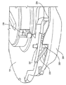
図17〜図20及び図38及び図39を参照すると、カムガイド式チャージャ(充填)機構365は、往復プランジャ又はピストン350と、弾性的にたわみ可能なカムアーム373とを有する。プランジャ350は、スライダ362上で並進可能に取り付けられて、駆動ばねによって駆動され、それにより、作動ランセットをその穿刺行程に沿って推進することができる。好ましくは、プランジャ350は、作動ランセットの足部又は他の部分を受容し係合する顎部(ジョー)356を形成するリセスを有する。プランジャ350には好ましくは、プランジャを作動準備状態に保持して、起動前に駆動ばねに力を蓄えさせ、起動ボタンを作動させることによって解放され、それにより、作動ランセットをその穿刺行程に沿って推進することができる捕捉部(キャッチ部)355を有するたわみ解放アーム353がさらに設けられている。また、ロック従動部(ロックフォロワ)374が、プランジャ350から(すなわち、プランジャの底部から下向きに)延出して、スライダ362によって画定された直立ロック壁375に係合するようになっている。また、チャージ従動部(チャージフォロワ)376が、プランジャ350から(すなわち、プランジャの底部から下向きに、且つロック従動部374から間隔をおいて)延出している。
Referring to FIGS. 17-20, 38 and 39, the cam-guided charger (filling)
弾性的にたわみ可能なカムアーム373は好ましくは、スライダ362と一体成形され、且つ成形プラスチックで形成されるが、他の材料及び製造技法を使用してもよい。カムアーム373の材料及び寸法は、それが弾性的にたわみ可能であるように選択される。また、アーム373は、チャージカム面378及びたわみカム面379を画定する片持ち式部材377を有する。たわみカム面379は、プランジャのチャージ従動部376に係合し、それにより、カムアーム373をたわませる。また、チャージカム面378は、プランジャのチャージ従動部376に係合してそれを案内し、それにより、プランジャ350を後退させて駆動ばねに力を蓄えさせるようにする。
Elastically
さらに、壁380が、ハウジングベース306から上向きに延出しており、スライダ362がその伸張/後退行程を移動するとき、静止したままである。壁380には、ランセットがその穿刺行程に沿って推進されるとき、プランジャのチャージ従動部376が通過する開口381が設けられている。
Further, the
図40〜図44は、前進機構360のカムガイド式チャージャ機構365の動作の詳細を示す。図40は、スライダ362が図17の後退位置にあるときのカムアーム373及びプランジャ350のチャージ従動部376の位置を示す。この一連の図面にはプランジャ350の従動部374及び376が示されているが、わかりやすくするために、プランジャの本体は示されていない。図41では、スライダ362が(直線方向矢印で示すように)引き出し中/伸張中であり、それにより、たわみカム面379がプランジャのチャージ従動部376に係合するようになり、その係合により、カムアーム373が(曲線状の方向矢印で示すように)たわむ。従動部374及び376及びプランジャ350は、スライダ362の行程方向に移動しないので、それらは静止したままである。図42では、スライダ362が図20の完全伸張位置へ移動しており、たわみカム面379は、チャージ従動部376を越えて側方に移動しており、それにより、カムアーム373は、壁380に隣接したニュートラル位置に弾性的に戻っている。
40 to 44 show details of the operation of the cam guide
図43では、スライダ362が(方向矢印で示すように)押し込み中/後退中であり、それにより、今度はチャージカム面378がプランジャのチャージ従動部376に係合するようになる。カムアーム373は、隙間なく壁380に隣接する位置にあり、それにより、チャージ従動部376を滑らせる、又は持ち上げることができ、また、カム部材377は、チャージ従動部にこの方向から出会ったときにたわむことを防止するため、曲がっている。このように、カムアーム373は、チャージ従動部376を位置付けるための一方向弁として機能し、それにより、チャージ従動部376をチャージカム面378によって駆動することができる。次に、スライダを押し込む/後退させるとき、チャージカム面378はチャージ従動部376を、したがってプランジャ350を(方向矢印で示すように)戻り方向に駆動し、それにより、駆動機構に力を蓄えさせることができる。図44では、スライダ362が図17の完全後退位置へ押し戻されている/後退している。この位置では、チャージカム面378がプランジャ350を駆動してその作動準備位置へ戻しており、プランジャ350の解放アームキャッチ355が係合し、それにより、プランジャをこの作動準備位置に保持することができる。
In FIG. 43, the
キャリア318は、第1実施形態のキャップガイドトラック19と同様なキャップガイドトラックを有する。キャップガイドトラックは、ランセットキャップを所定位置に保持し、それにより、活動ランセットをプランジャ350が後退させるとき、活動ランセットはそのキャップから離脱される。また、カムガイド式キャップ変位機構366に関連して説明したように、ランセットキャップが穿刺行程経路からその交差方向に変位させられるとき、キャップガイドトラックがランセットキャップを案内する。
The
次に、起動ボタンの作動により、プランジャ350をその作動準備位置から解放し、それにより、作動ランセットをその穿刺行程に沿って推進することができる。図44に示された位置では、スライダ362から上向きに延出したロック壁375が、プランジャ350のロック従動部374の経路上の遮断位置から側方へ移動している。また、チャージ従動部376は、静止壁380の開口381と整合した位置に留まっている。そのため、プランジャ350の移動経路上に障害物がまったくなく、それは起動準備ができている。被験体の皮膚に穿刺するために穿刺装置300を起動した後、前進機構360のカムガイド式チャージャ機構365は、再び図40に示した位置にある。
The activation button can then be actuated to release the
図17〜図21及び図45及び図46を参照すると、カムガイド式キャップ変位機構366には、離脱したランセットキャップを作動ランセットの穿刺行程経路から外れたその交差方向に移動させるために、カム面384に沿って進む従動部(フォロワ)383を有するリフター部材(昇降部材)382が設けられている。リフター382は、穿刺移動経路に対して直角方向に移動し、且つリフターガイドトラック385によって案内される。また、リフター382は好ましくはフォーク形であり、2つの(又は他の数の)尖った先に変位面386及び開口387を有し、ランセット本体がその穿刺位置へ移動するとき、ランセット本体がその開口を通過する。カム面384は好ましくは、スライダ362内に画定されたスロットによって少なくとも部分的に形成され、これは、リフター382の位置を確実に制御するために、上昇カム面384a及び下降カム面384bを有する。代替の実施形態では、カムガイド式キャップ変位機構366は、リフターの上昇又は下降のいずれか一方を行う1つのみのカム面と、リフタを他方の非カム駆動方向に移動させるばね部材とを有する。
Referring to FIGS. 17-21, 45 and 46, the cam-guided
図47〜図53は、前進機構360のカムガイド式キャップ変位機構366の動作の詳細を示す。図47は、スライダ362が図17の後退位置にあるとき、リフター従動部383が、上昇カム面384aとの係合によってその上昇位置にあるところを示す。図48では、スライダ362が(方向矢印で示すように)引き出される/伸張するとき、リフター従動部383が下降カム面384bに沿って下方へ案内されている。図49では、リフター従動部383が下降して、スライダ362が、リフター従動部383を越えて側方にさらに引き出されて/伸張している。図48及び図49に示す位置は、それぞれ図18及び図19に示したスライダ位置に対応する。リフター382がその下降位置にあるとき、それは邪魔にならない位置にあり、それにより、割り出しラチェット機構363によって次のランセットを作動位置へ回転前進させることができる。リフター382がより下方へ移動するのを防止するために、穿刺装置300は、リフター従動部383が乗るスライダ362用のベース、ハウジング302のベース306の内壁上のガイド面、及び/又はスライダ362、ハウジング302、リフターガイドトラック385又は穿刺装置上のいずれかの場所の停止面を備えてもよい。また、図50は、スライダが図20の完全伸張位置にあるときにリフター従動部383がスライダ362に対してとる下降位置を示す。
47 to 53 show details of the operation of the cam guide type
図51では、スライダ362が、(方向矢印で示すように)側方へ下降ーリフタ従動部383を越えて押し戻されている/後退している。スライダ後退運動のこの第1部分の間、リフター382は下降状態のままである一方、カムガイド式チャージャ機構365の動作により、ランセットキャップ328がランセット本体324から離脱されつつある。図52では、スライダ362がスライダ後退運動の第2部分においてさらに押し込まれる/後退するとき、リフター従動部383は、上昇カム面384aに沿って上方へ駆動されている。また、図53において、スライダ362が図17のその完全後退位置に押し戻される/後退するとき、リフター従動部383が上昇カム面384aによってその上昇位置へ駆動されて、リフター382がその上昇位置に戻る。
In FIG. 51, the
リフタ382が上昇するとき、その変位面386が、その時点において離脱しているランセットキャップ328を作動ランセット320の穿刺移動経路外へ押し出す。好ましくは、変位したランセットキャップ328は、ランセットキャリア318のキャップガイドトラックの機能部によってそこに保持される。ここで、ランセット320をその穿刺行程に発射することができ、その間に、ランセットは、その穿刺位置へ移動するとき、リフター382内の開口387を通過する。ランセット320がリフターの開口387を通過するとき、この開口は作動ランセットの位置付けを維持し、且つランセットキャリアの回転を防止する。
When the
穿刺装置300の構造、動作及び使用の詳細を説明してきたが、ここで図22a〜図22fを参照し、これらは新しいランセットカートリッジ310を穿刺装置300のハウジング302に挿入するプロセスを示す。図22aでは、前進機構360のスライダ362を第1/後退位置から第2/伸張位置へ引き出している。図22bでは、ハウジング302を開いている。図22cでは、ランセットカートリッジ310を開放状態のハウジング302内に挿入している。図22dでは、ハウジング302を閉鎖している。図22eでは、スライダ362をその後退位置へ押し戻している。ここで、穿刺装置300は使用準備ができる。図22fでは、起動ボタン320を押圧しており、それにより、ランセットのうちの最初のもので穿刺するように穿刺装置300を起動することができる。
Having described details of the structure, operation and use of the lancing
図22gに示されているように、前進機構360は、スライダ362から延出してそれを押し引きできるようにするハンドル361を有する。ハンドル361は、好ましくはC字形であって、クラムシェルハウジング302の上下部分の周囲をクランプのように包み込む2つのフランジ361aを備える。前進機構360が完全後退位置にあるとき、ハンドル361のフランジ361aがハウジングの上部及び底部に重なり、それにより、ハウジングを閉鎖状態にロックすることができる。これにより、ランセットが作動位置へ前進して、駆動部材がチャージされたとき即ち力を蓄えたとき、ユーザがハウジング302を開くことが防止される。これが、図22a〜図22eのステップに示されているように、前進機構360を引き出し、且つ押し込む理由である。ハンドル361のフランジ361aを十分に長くし、それにより、ハウジング302を開くために必要な隙間を設ける(すなわち、フランジ361aがハウジングの上部及び底部に重ならない)ために、ハンドルを完全に引き出さなければならない。これにより、チャージ済みランセットが作動位置から進められ、次の未チャージランセットが作動位置へ進められるまで、ハウジング302を決して開くことができない。
As shown in FIG. 22g, the
図23a〜図23cは、穿刺のためにランセットのうちの次のものを前進させるプロセスを示す。図23aでは、前進機構360のスライダ362を後退位置から伸張位置へ引き出しており、それにより、キャリアを回転させることができ、これにより、使用済みランセットが作動位置外へ進められ、次のランセットが作動位置へ進められる。図23bでは、スライダ362をその後退位置へ押し戻しており、それにより、作動ランセットをチャージ即ち充填するとともにキャップを外し、次にキャップを穿刺行程経路外へ変位させることができる。ここで、穿刺装置300は、次のランセットで穿刺するための起動準備ができる。また、図23cでは、起動ボタン320が押圧されており、それにより、次のランセットで穿刺するように穿刺装置300が起動される。
Figures 23a-23c illustrate the process of advancing the next of the lancets for puncture. In FIG. 23a, the
図24a〜図24eは、ランセットの各々を作動位置へ順次前進させて使用した後に使用済みカートリッジ310を取り外すプロセスを示す。図24aでは、前進機構360のスライダ362を後退位置から伸張位置へ引き出しており、それにより、ハウジング302のロックを解除することができる。図24bでは、ハウジング302を開いている。図24cでは、使用済みカートリッジ310をハウジング302から取り外している。所望ならば、ここで新しいカートリッジ310をハウジング302に挿入して使用できるようにすることができる。そうでなければ、図24dでは、ハウジングをさしあたり閉鎖し、図24eでは、スライダ362をその後退位置へ押し戻し、それにより、ハウジングを再ロックすることができる。そして、新しいカートリッジ310を後に、図22a〜図22fに示すプロセスに従って挿入することができる。
FIGS. 24a-24e illustrate the process of removing the used
図25a〜図25eは、ランセットのすべてを使い切る前に部分的に使用済みのカートリッジ310を取り外すプロセスを示す。図25aでは、前進機構360のスライダ362を後退位置から伸張位置へ引き出しており、それにより、ハウジング302のロックを解除することができる。図25bでは、ハウジング302を開いている。図25cでは、部分的に使用済みのカートリッジ310をハウジング302から取り外している。図25dでは、ハウジング302を閉鎖している。また図25eでは、スライダ362をその後退位置へ押し戻し、それにより、ハウジング302を再ロックすることができる。
Figures 25a-25e illustrate the process of removing a partially used
図26a〜図26fは、すべてのランセットを使い切る前に取り外された部分的に使用済みのカートリッジ310を後に再挿入するプロセスを示す。図26aでは、前進機構360のスライダ362を後退位置から伸張位置へ引き出しており、それによりハウジング302のロックを解除することができる。図26bでは、ハウジング302を開いている。図26cでは、部分的に使用済みのカートリッジ310をハウジング302内に再挿入している。図26dでは、ハウジング302を閉鎖している。図26eでは、スライダ362をその後退位置へ押し戻しており、それにより、ハウジング302を再ロックすることができる。また、図26fでは、起動ボタン320を押圧しており、それにより、その時に作動中のランセットで穿刺するように穿刺装置300を起動させることができる。もちろん、代わりに新しいカートリッジ310を、図22a〜図22fに示したプロセスに従って挿入することができる。
Figures 26a-26f illustrate the process of later reinserting a partially used
図27a〜図27fは、詰まりを起こした場合に穿刺装置300の詰まりを取り除くプロセスを示す。図27aでは、前進機構360のフェールセーフ解除機構363を起動させており、それにより、前進機構を解除することができる。好ましくは、フェールセーフ解除機構363は、ハウジング302に小さい開口を有し、それを通して薄くて細長い物体(すなわち、紙クリップのワイヤ又はペン先)を挿入して、スライダ362を自在に移動できるようにする解除部に係合させることができる。図27bでは、スライダ362を後退位置から伸張位置へ引き出しており、それにより、ハウジング302のロックを解除することができる。図27cでは、ハウジング302を開いている。図27dでは、詰まったランセットカートリッジ310をハウジングから取り外している。図27eでは、ハウジングを閉鎖している。また、図27fでは、スライダ362をその後退位置へ押し戻しており、それにより、ハウジング302を再ロックすることができる。ここで、新しいカートリッジ310を、図22a〜図22fに示したプロセスに従って挿入してもよく、或いは、これをハウジング302の閉鎖前に行うこともできる。
FIGS. 27a-f show the process of clearing the lancing
図28は、穿刺深さを設定するための深さ調節機構311の使用を示す。深さ調節機構311は、図13に示す深さ制御リング212か、又はランセットの穿刺深さを選択的に制御するための別の通常の機構を備えてもよい。
FIG. 28 illustrates the use of the
好適且つ例示的な実施形態を参照しながら本発明を説明してきたが、添付の特許請求の範囲によって規定される本発明の範囲内においてさまざまな修正、追加及び削除が行われることは、当業者には理解されるであろう。 Although the invention has been described with reference to preferred and exemplary embodiments, it will be appreciated by those skilled in the art that various modifications, additions and deletions can be made within the scope of the invention as defined by the appended claims. Will be understood.
Claims (40)
前記カートリッジアセンブリを受容するハウジングと、
前記ランセットを作動ランセット位置へ順次前進させるようにする割り出しラチェット機構と、
前記ランセットのうちの作動位置のランセットに係合してそれを後退させ、それにより、作動位置の対応するキャップを離脱させることができ、且つ前記作動位置のランセットを穿刺行程に沿って駆動するようにする駆動部材を有する駆動機構と、
前記駆動部材を後退させるようにするチャージャ機構と、
前記作動位置の離脱したランセットキャップに係合して、それを前記作動位置のランセットの前記穿刺行程経路外へ移動させるようにするカム変位機構と、
前記ハウジングに対して摺動可能であるスライダとを備え、該スライダを第1の位置と第2の位置との間で移動させることにより、前記割り出しラチェット機構、前記チャージャ機構及び前記キャップ変位機構を作動させるように該スライダが構成されている、穿刺装置。 A lancing device for use with a cartridge assembly having an array of lancets, each lancet having a removable cap,
A housing for receiving the cartridge assembly;
An index ratchet mechanism for sequentially advancing the lancet to an operating lancet position;
Engage with and retract the lancet in the operative position of the lancet so that the corresponding cap in the operative position can be removed and drive the lancet in the operative position along the puncture stroke A drive mechanism having a drive member to be
A charger mechanism for retracting the drive member;
A cam displacement mechanism that engages the lancet cap that has been disengaged from the operating position and moves it out of the puncture stroke path of the lancet at the operating position;
A slider that is slidable with respect to the housing, and moving the slider between a first position and a second position so that the index ratchet mechanism, the charger mechanism, and the cap displacement mechanism are A puncture device, wherein the slider is configured to operate.
前記カートリッジアセンブリを受容するハウジングと、
前記ランセットのうちの作動位置のランセットに係合してそれを作動準備位置へ後退させ、且つ前記作動位置のランセットを穿刺行程に沿って駆動するようにする駆動部材を有する駆動機構と、
前記駆動部材を後退させるようにするカムガイド式チャージャ機構と
を備える穿刺装置。 A lancing device for use with a cartridge assembly having an array of lancets adapted to be sequentially advanced to an operating position,
A housing for receiving the cartridge assembly;
A drive mechanism having a drive member that engages the lancet in the operative position of the lancet to retract the lancet to the operation ready position and drives the lancet in the operative position along the puncturing stroke;
A puncture device comprising a cam-guided charger mechanism for retracting the drive member.
前記カートリッジアセンブリを受容するハウジングと、
前記ランセットのうちの作動位置のランセットに係合してそれを後退させ、それにより、作動位置の対応するキャップを離脱させることができ、且つ前記作動位置のランセットを穿刺行程に沿って駆動するようにする駆動部材を有する駆動機構と、
前記作動位置の離脱したランセットキャップに係合して、それを前記作動位置のランセットの前記穿刺行程経路外へ移動させるようにするカムガイド式キャップ変位機構と
を備える穿刺装置。 A lancing device for use with a cartridge assembly having an array of lancets, each lancet having a removable cap,
A housing for receiving the cartridge assembly;
Engage with and retract the lancet in the operative position of the lancet so that the corresponding cap in the operative position can be removed and drive the lancet in the operative position along the puncture stroke A drive mechanism having a drive member to be
A puncture device comprising a cam-guided cap displacement mechanism that engages with the lancet cap that has been detached from the operating position and moves it outside the puncture stroke path of the lancet at the operating position.
ハウジングと、
該ハウジング内に回転可能に取り付けられたキャリアと、
該キャリアによって担持され、各々が離脱可能な保護キャップを有しかつ穿刺行程経路に沿って移動可能であるランセットのアレイと、
前記キャリアから前記カートリッジハウジング外へ延出した複数のラチェット歯と
を備え、前記歯は、前記爪に順次係合して、穿刺のために作動位置へ前進するように構成される、カートリッジアセンブリ。 A cartridge assembly for a puncture device having a lancet indexing ratchet mechanism having a nail,
A housing;
A carrier rotatably mounted in the housing;
An array of lancets carried by the carrier, each having a removable protective cap and movable along the puncture path;
A cartridge assembly comprising a plurality of ratchet teeth extending out of the cartridge housing from the carrier, wherein the teeth are sequentially engaged with the pawl and advanced to an operating position for puncturing.
Applications Claiming Priority (2)
| Application Number | Priority Date | Filing Date | Title |
|---|---|---|---|
| US58411504P | 2004-06-30 | 2004-06-30 | |
| PCT/US2005/023155 WO2006004859A2 (en) | 2004-06-30 | 2005-06-30 | Lancing device and multi-lancet cartridge |
Publications (1)
| Publication Number | Publication Date |
|---|---|
| JP2008504893A true JP2008504893A (en) | 2008-02-21 |
Family
ID=35783339
Family Applications (1)
| Application Number | Title | Priority Date | Filing Date |
|---|---|---|---|
| JP2007519406A Pending JP2008504893A (en) | 2004-06-30 | 2005-06-30 | Puncture device and multi-lancet cartridge |
Country Status (4)
| Country | Link |
|---|---|
| US (2) | US7837633B2 (en) |
| EP (1) | EP1804663A4 (en) |
| JP (1) | JP2008504893A (en) |
| WO (1) | WO2006004859A2 (en) |
Cited By (5)
| Publication number | Priority date | Publication date | Assignee | Title |
|---|---|---|---|---|
| JP2013505795A (en) * | 2009-09-28 | 2013-02-21 | ファセット・テクノロジーズ・エルエルシー | Cartridge type feed mechanism |
| JP2014522709A (en) * | 2011-08-03 | 2014-09-08 | インテュイティ メディカル インコーポレイテッド | Body fluid extraction and analysis apparatus and method |
| JP2015503982A (en) * | 2012-01-18 | 2015-02-05 | エフ ホフマン−ラ ロッシュ アクチェン ゲゼルシャフト | Analysis system for examining body fluid and method of operating the analysis system |
| US11933789B2 (en) | 2009-11-30 | 2024-03-19 | Intuity Medical, Inc. | Calibration material delivery devices and methods |
| US11986293B2 (en) | 2008-06-06 | 2024-05-21 | Intuity Medical, Inc. | Medical diagnostic devices and methods |
Families Citing this family (77)
| Publication number | Priority date | Publication date | Assignee | Title |
|---|---|---|---|---|
| US6391005B1 (en) | 1998-03-30 | 2002-05-21 | Agilent Technologies, Inc. | Apparatus and method for penetration with shaft having a sensor for sensing penetration depth |
| US8641644B2 (en) | 2000-11-21 | 2014-02-04 | Sanofi-Aventis Deutschland Gmbh | Blood testing apparatus having a rotatable cartridge with multiple lancing elements and testing means |
| US9795747B2 (en) | 2010-06-02 | 2017-10-24 | Sanofi-Aventis Deutschland Gmbh | Methods and apparatus for lancet actuation |
| US9427532B2 (en) | 2001-06-12 | 2016-08-30 | Sanofi-Aventis Deutschland Gmbh | Tissue penetration device |
| WO2002100251A2 (en) | 2001-06-12 | 2002-12-19 | Pelikan Technologies, Inc. | Self optimizing lancing device with adaptation means to temporal variations in cutaneous properties |
| US7981056B2 (en) | 2002-04-19 | 2011-07-19 | Pelikan Technologies, Inc. | Methods and apparatus for lancet actuation |
| US8337419B2 (en) | 2002-04-19 | 2012-12-25 | Sanofi-Aventis Deutschland Gmbh | Tissue penetration device |
| WO2002100460A2 (en) | 2001-06-12 | 2002-12-19 | Pelikan Technologies, Inc. | Electric lancet actuator |
| US7041068B2 (en) | 2001-06-12 | 2006-05-09 | Pelikan Technologies, Inc. | Sampling module device and method |
| EP1404235A4 (en) | 2001-06-12 | 2008-08-20 | Pelikan Technologies Inc | METHOD AND APPARATUS FOR INTEGRATED LANCET LAUNCH DEVICE ON BLOOD SAMPLING CARTRIDGE |
| US9226699B2 (en) | 2002-04-19 | 2016-01-05 | Sanofi-Aventis Deutschland Gmbh | Body fluid sampling module with a continuous compression tissue interface surface |
| DE20213607U1 (en) * | 2002-02-21 | 2003-07-03 | Paul Hartmann AG, 89522 Heidenheim | Blood analyzer for the determination of an analyte |
| US7175642B2 (en) | 2002-04-19 | 2007-02-13 | Pelikan Technologies, Inc. | Methods and apparatus for lancet actuation |
| US7297122B2 (en) | 2002-04-19 | 2007-11-20 | Pelikan Technologies, Inc. | Method and apparatus for penetrating tissue |
| US7976476B2 (en) | 2002-04-19 | 2011-07-12 | Pelikan Technologies, Inc. | Device and method for variable speed lancet |
| US7713214B2 (en) | 2002-04-19 | 2010-05-11 | Pelikan Technologies, Inc. | Method and apparatus for a multi-use body fluid sampling device with optical analyte sensing |
| US7674232B2 (en) | 2002-04-19 | 2010-03-09 | Pelikan Technologies, Inc. | Method and apparatus for penetrating tissue |
| US8702624B2 (en) | 2006-09-29 | 2014-04-22 | Sanofi-Aventis Deutschland Gmbh | Analyte measurement device with a single shot actuator |
| US8784335B2 (en) | 2002-04-19 | 2014-07-22 | Sanofi-Aventis Deutschland Gmbh | Body fluid sampling device with a capacitive sensor |
| US7901362B2 (en) | 2002-04-19 | 2011-03-08 | Pelikan Technologies, Inc. | Method and apparatus for penetrating tissue |
| US8360992B2 (en) | 2002-04-19 | 2013-01-29 | Sanofi-Aventis Deutschland Gmbh | Method and apparatus for penetrating tissue |
| US7229458B2 (en) | 2002-04-19 | 2007-06-12 | Pelikan Technologies, Inc. | Method and apparatus for penetrating tissue |
| US8221334B2 (en) | 2002-04-19 | 2012-07-17 | Sanofi-Aventis Deutschland Gmbh | Method and apparatus for penetrating tissue |
| US8267870B2 (en) | 2002-04-19 | 2012-09-18 | Sanofi-Aventis Deutschland Gmbh | Method and apparatus for body fluid sampling with hybrid actuation |
| US9314194B2 (en) | 2002-04-19 | 2016-04-19 | Sanofi-Aventis Deutschland Gmbh | Tissue penetration device |
| US7491178B2 (en) | 2002-04-19 | 2009-02-17 | Pelikan Technologies, Inc. | Method and apparatus for penetrating tissue |
| US8372016B2 (en) | 2002-04-19 | 2013-02-12 | Sanofi-Aventis Deutschland Gmbh | Method and apparatus for body fluid sampling and analyte sensing |
| US9795334B2 (en) | 2002-04-19 | 2017-10-24 | Sanofi-Aventis Deutschland Gmbh | Method and apparatus for penetrating tissue |
| US7547287B2 (en) | 2002-04-19 | 2009-06-16 | Pelikan Technologies, Inc. | Method and apparatus for penetrating tissue |
| US9248267B2 (en) | 2002-04-19 | 2016-02-02 | Sanofi-Aventis Deustchland Gmbh | Tissue penetration device |
| US7892183B2 (en) | 2002-04-19 | 2011-02-22 | Pelikan Technologies, Inc. | Method and apparatus for body fluid sampling and analyte sensing |
| US7232451B2 (en) | 2002-04-19 | 2007-06-19 | Pelikan Technologies, Inc. | Method and apparatus for penetrating tissue |
| US7331931B2 (en) | 2002-04-19 | 2008-02-19 | Pelikan Technologies, Inc. | Method and apparatus for penetrating tissue |
| US7909778B2 (en) | 2002-04-19 | 2011-03-22 | Pelikan Technologies, Inc. | Method and apparatus for penetrating tissue |
| US8579831B2 (en) | 2002-04-19 | 2013-11-12 | Sanofi-Aventis Deutschland Gmbh | Method and apparatus for penetrating tissue |
| US8574895B2 (en) | 2002-12-30 | 2013-11-05 | Sanofi-Aventis Deutschland Gmbh | Method and apparatus using optical techniques to measure analyte levels |
| DE602004028463D1 (en) | 2003-05-30 | 2010-09-16 | Pelikan Technologies Inc | METHOD AND DEVICE FOR INJECTING LIQUID |
| EP1633235B1 (en) | 2003-06-06 | 2014-05-21 | Sanofi-Aventis Deutschland GmbH | Apparatus for body fluid sampling and analyte sensing |
| WO2006001797A1 (en) | 2004-06-14 | 2006-01-05 | Pelikan Technologies, Inc. | Low pain penetrating |
| EP1663001A2 (en) * | 2003-08-20 | 2006-06-07 | Facet Technologies, LLC | Multi-lancet device with sterility cap repositioning mechanism |
| US8282576B2 (en) | 2003-09-29 | 2012-10-09 | Sanofi-Aventis Deutschland Gmbh | Method and apparatus for an improved sample capture device |
| US9351680B2 (en) | 2003-10-14 | 2016-05-31 | Sanofi-Aventis Deutschland Gmbh | Method and apparatus for a variable user interface |
| US8221332B2 (en) * | 2003-11-12 | 2012-07-17 | Facet Technologies, Llc | Multi-lancet cartridge and lancing device |
| US7822454B1 (en) | 2005-01-03 | 2010-10-26 | Pelikan Technologies, Inc. | Fluid sampling device with improved analyte detecting member configuration |
| WO2005065414A2 (en) | 2003-12-31 | 2005-07-21 | Pelikan Technologies, Inc. | Method and apparatus for improving fluidic flow and sample capture |
| PL1732627T3 (en) | 2004-03-31 | 2010-09-30 | Lilly Co Eli | Injection apparatus having a needle cassette for delivering a pharmaceutical liquid |
| EP1751546A2 (en) | 2004-05-20 | 2007-02-14 | Albatros Technologies GmbH & Co. KG | Printable hydrogel for biosensors |
| EP1765194A4 (en) | 2004-06-03 | 2010-09-29 | Pelikan Technologies Inc | METHOD AND APPARATUS FOR MANUFACTURING A DEVICE FOR SAMPLING LIQUIDS |
| US9775553B2 (en) | 2004-06-03 | 2017-10-03 | Sanofi-Aventis Deutschland Gmbh | Method and apparatus for a fluid sampling device |
| US9788771B2 (en) | 2006-10-23 | 2017-10-17 | Abbott Diabetes Care Inc. | Variable speed sensor insertion devices and methods of use |
| US8652831B2 (en) | 2004-12-30 | 2014-02-18 | Sanofi-Aventis Deutschland Gmbh | Method and apparatus for analyte measurement test time |
| JP4642082B2 (en) * | 2005-09-29 | 2011-03-02 | 泉株式会社 | Lancet assembly and lancing device |
| US8801631B2 (en) | 2005-09-30 | 2014-08-12 | Intuity Medical, Inc. | Devices and methods for facilitating fluid transport |
| WO2008064333A2 (en) * | 2006-11-21 | 2008-05-29 | Stat Medical Devices, Inc. | Lancet device utilizing a revolver-type cartridge, revolver-type cartridge, and method of making and/or using the cartridge and the lancet device |
| US9392968B2 (en) * | 2008-01-23 | 2016-07-19 | Stat Medical Devices, Inc. | Lancet needle cartridge, cartridge lancet device, and method of using and making the same |
| US9386944B2 (en) | 2008-04-11 | 2016-07-12 | Sanofi-Aventis Deutschland Gmbh | Method and apparatus for analyte detecting device |
| US8029526B2 (en) * | 2008-08-14 | 2011-10-04 | Abbott Diabetes Care Inc. | Cocking mechanism for lancing device |
| US9375169B2 (en) | 2009-01-30 | 2016-06-28 | Sanofi-Aventis Deutschland Gmbh | Cam drive for managing disposable penetrating member actions with a single motor and motor and control system |
| US9517027B2 (en) * | 2009-07-10 | 2016-12-13 | Facet Techonologies, Llc | Advancement mechanism for cartridge-based devices |
| US8834553B2 (en) | 2009-09-11 | 2014-09-16 | Gi Dynamics, Inc. | Anchors with biodegradable constraints |
| US8965476B2 (en) | 2010-04-16 | 2015-02-24 | Sanofi-Aventis Deutschland Gmbh | Tissue penetration device |
| USD648852S1 (en) * | 2010-11-16 | 2011-11-15 | Sterilance Medical (Suzhou) Inc. | Heel incision safety lancet |
| CA2818165C (en) | 2010-11-19 | 2016-02-09 | Eli Lilly And Company | Needle magazine for medication injection device |
| US9717452B2 (en) | 2010-12-30 | 2017-08-01 | Roche Diabetes Care, Inc. | Handheld medical diagnostic devices with lancing speed control |
| US8158428B1 (en) | 2010-12-30 | 2012-04-17 | General Electric Company | Methods, systems and apparatus for detecting material defects in combustors of combustion turbine engines |
| US8852123B2 (en) | 2010-12-30 | 2014-10-07 | Roche Diagnostics Operations, Inc. | Handheld medical diagnostic devices housing with sample transfer |
| WO2014052362A1 (en) * | 2012-09-27 | 2014-04-03 | Facet Technologies, Llc | Depth-adjust mechanism for lancing device |
| USD806864S1 (en) * | 2016-08-19 | 2018-01-02 | Sterilance Medical (Suzhou) Inc. | Disposable heel blood collecting device |
| CN110461217B (en) | 2017-01-23 | 2022-09-16 | 雅培糖尿病护理公司 | Systems, devices, and methods for analyte sensor insertion |
| WO2018204476A1 (en) | 2017-05-03 | 2018-11-08 | Abbott Diabetes Care Inc. | Systems, devices, and methods with duration-based adjustment of sensor data |
| USD872260S1 (en) * | 2017-12-11 | 2020-01-07 | Deka Products Limited Partnership | Reservoir |
| ES3026571T3 (en) | 2018-06-07 | 2025-06-11 | Abbott Diabetes Care Inc | Analyte monitoring systems |
| US12521041B2 (en) | 2018-12-21 | 2026-01-13 | Abbott Diabetes Care Inc. | Systems, devices, and methods for analyte sensor insertion |
| PL429290A1 (en) * | 2019-03-15 | 2020-09-21 | Uniwersytet Medyczny w Łodzi | Device for collecting blood samples and analysing blood parameters |
| EP4203819B1 (en) | 2020-08-31 | 2024-07-31 | Abbott Diabetes Care Inc. | Systems, devices, and methods for analyte sensor insertion |
| CN116709978A (en) | 2020-12-31 | 2023-09-05 | 雅培糖尿病护理公司 | Embedded Systems in Medical Monitoring Systems |
| CN115886810B (en) * | 2022-12-13 | 2025-11-21 | 山东威高血液净化制品股份有限公司 | Pipeline sampling port |
Citations (2)
| Publication number | Priority date | Publication date | Assignee | Title |
|---|---|---|---|---|
| WO2003070099A1 (en) * | 2002-02-21 | 2003-08-28 | Facet Technologies, Llc | Blood analyzer and pricking device for use in blood analysis |
| WO2004041082A1 (en) * | 2002-11-01 | 2004-05-21 | Pelikan Technologies, Inc. | Method and apparatus for body fluid sampling |
Family Cites Families (103)
| Publication number | Priority date | Publication date | Assignee | Title |
|---|---|---|---|---|
| US3760809A (en) | 1971-10-22 | 1973-09-25 | Damon Corp | Surgical lancet having casing |
| USD245040S (en) | 1976-02-25 | 1977-07-12 | Ryder International Corporation | Surgical lancet |
| US4643189A (en) | 1985-02-19 | 1987-02-17 | W. T. Associates | Apparatus for implementing a standardized skin incision |
| USD297978S (en) | 1985-08-16 | 1988-10-04 | Baxter Travenol Laboratories, Inc. | Automatic retractable lancet for bleed time determination |
| IL80628A0 (en) | 1985-11-18 | 1987-02-27 | Bajada Serge | Apparatus for testing the sensory system in humans or animals |
| US4794926A (en) | 1986-11-24 | 1989-01-03 | Invictus, Inc. | Lancet cartridge |
| US4892097A (en) | 1988-02-09 | 1990-01-09 | Ryder International Corporation | Retractable finger lancet |
| US4995402A (en) | 1988-10-12 | 1991-02-26 | Thorne, Smith, Astill Technologies, Inc. | Medical droplet whole blood and like monitoring |
| US4983178A (en) | 1988-11-14 | 1991-01-08 | Invictus, Inc. | Lancing device |
| US5196025A (en) | 1990-05-21 | 1993-03-23 | Ryder International Corporation | Lancet actuator with retractable mechanism |
| DE4212315A1 (en) | 1992-04-13 | 1993-10-14 | Boehringer Mannheim Gmbh | Blood lancet device for drawing blood for diagnostic purposes |
| US5477209A (en) | 1992-05-01 | 1995-12-19 | Adonis Incorporated | Remote controlled safety light having increased noise discrimination |
| US5318583A (en) | 1992-05-05 | 1994-06-07 | Ryder International Corporation | Lancet actuator mechanism |
| IL107396A (en) | 1992-11-09 | 1997-02-18 | Boehringer Mannheim Gmbh | Method and apparatus for analytical determination of glucose in a biological matrix |
| DE4243142A1 (en) | 1992-12-19 | 1994-06-23 | Boehringer Mannheim Gmbh | Device for in-vivo determination of an optical property of the aqueous humor of the eye |
| EP0644412A3 (en) | 1993-09-17 | 1995-08-09 | Boehringer Mannheim Gmbh | Method for the analysis of liquids and suspensions of clinical interest. |
| DE4337570A1 (en) | 1993-11-04 | 1995-05-11 | Boehringer Mannheim Gmbh | Method for the analysis of glucose in a biological matrix |
| US5395388A (en) | 1993-11-15 | 1995-03-07 | Schraga; Steven | Single unit lancet device |
| US5464418A (en) | 1993-12-09 | 1995-11-07 | Schraga; Steven | Reusable lancet device |
| DE4415896A1 (en) | 1994-05-05 | 1995-11-09 | Boehringer Mannheim Gmbh | Analysis system for monitoring the concentration of an analyte in the blood of a patient |
| TW275570B (en) | 1994-05-05 | 1996-05-11 | Boehringer Mannheim Gmbh | |
| DE4417639A1 (en) | 1994-05-19 | 1995-11-23 | Boehringer Mannheim Gmbh | Analysis of concns. of substances in a biological sample |
| US5527334A (en) | 1994-05-25 | 1996-06-18 | Ryder International Corporation | Disposable, retractable lancet |
| US5476474A (en) | 1994-07-27 | 1995-12-19 | Ryder International Corporation | Rotary lancet |
| DE4427101A1 (en) | 1994-07-30 | 1996-02-01 | Boehringer Mannheim Gmbh | Apparatus and method for the optical characterization of the structure and composition of a scattering sample |
| US5514152A (en) | 1994-08-16 | 1996-05-07 | Specialized Health Products, Inc. | Multiple segment encapsulated medical lancing device |
| USD376203S (en) | 1994-10-31 | 1996-12-03 | Steven Schraga | Single use lancet |
| DE4445683A1 (en) | 1994-12-21 | 1996-06-27 | Boehringer Mannheim Gmbh | Method for examining a scattering medium with intensity-modulated light |
| EP0722691A1 (en) | 1994-12-24 | 1996-07-24 | Roche Diagnostics GmbH | System for determining properties of tissue |
| DE19509094A1 (en) | 1995-03-16 | 1996-09-26 | Boehringer Mannheim Gmbh | Quantitative transmission spectroscopy using sample carriers with networks |
| US5628764A (en) | 1995-03-21 | 1997-05-13 | Schraga; Steven | Collar lancet device |
| DE19543020A1 (en) | 1995-11-18 | 1997-05-22 | Boehringer Mannheim Gmbh | Method and device for determining analytical data on the interior of a scattering matrix |
| EP0876595B1 (en) | 1996-01-26 | 2002-11-27 | Roche Diagnostics GmbH | Low-coherence interferometric device |
| IL125475A0 (en) | 1996-01-26 | 1999-03-12 | Boehringer Mannheim Gmbh | Process and device for determining an analyte contained in a scattering matrix |
| DE19604156A1 (en) | 1996-02-06 | 1997-08-07 | Boehringer Mannheim Gmbh | Skin cutting device for taking pain-free small amounts of blood |
| US5772677A (en) | 1996-09-24 | 1998-06-30 | International Technidyne Corporation | Incision device capable of automatic assembly and a method of assembly |
| US5776157A (en) | 1996-10-02 | 1998-07-07 | Specialized Health Products, Inc. | Lancet apparatus and methods |
| US6071249A (en) | 1996-12-06 | 2000-06-06 | Abbott Laboratories | Method and apparatus for obtaining blood for diagnostic tests |
| DE19721902A1 (en) | 1997-05-26 | 1998-12-03 | Boehringer Mannheim Gmbh | Method and device for in-vivo detection of the direction of Langer lines in the skin |
| US5984940A (en) | 1997-05-29 | 1999-11-16 | Atrion Medical Products, Inc. | Lancet device |
| EP1001701B1 (en) | 1997-08-09 | 2004-10-06 | Roche Diagnostics GmbH | Analytical device for in vivo analysis in the body of a patient |
| US5971941A (en) | 1997-12-04 | 1999-10-26 | Hewlett-Packard Company | Integrated system and method for sampling blood and analysis |
| US6036924A (en) * | 1997-12-04 | 2000-03-14 | Hewlett-Packard Company | Cassette of lancet cartridges for sampling blood |
| US6071294A (en) | 1997-12-04 | 2000-06-06 | Agilent Technologies, Inc. | Lancet cartridge for sampling blood |
| DE19840856B4 (en) | 1998-09-07 | 2008-04-10 | Roche Diagnostics Gmbh | System for obtaining a body fluid, lancet magazine, lancet, lancet set, lancing device and method for removing a lancet from a lancet magazine and use of the system |
| JP3361470B2 (en) | 1999-03-02 | 2003-01-07 | アプルス株式会社 | Lancet device for forming precisely controlled incidents |
| US6306152B1 (en) | 1999-03-08 | 2001-10-23 | Agilent Technologies, Inc. | Lancet device with skin movement control and ballistic preload |
| DE19919608A1 (en) | 1999-05-27 | 2000-11-30 | Roche Diagnostics Gmbh | Sample holder for the IR spectroscopy of sample liquids |
| SG85117A1 (en) | 1999-06-18 | 2001-12-19 | Surgilance Pte Ltd | Lancet assembly |
| US6168606B1 (en) | 1999-11-10 | 2001-01-02 | Palco Labs, Inc. | Single-use lancet device |
| FR2797579A1 (en) | 1999-08-16 | 2001-02-23 | Jean Yves Rouviere | Lancing pen for use by diabetics has hollow body containing disposable lancets |
| USD444557S1 (en) | 1999-10-19 | 2001-07-03 | Facet Technologies, Llc | Lancing device |
| US6228100B1 (en) | 1999-10-25 | 2001-05-08 | Steven Schraga | Multi-use lancet device |
| EP1271136B1 (en) | 2000-02-23 | 2009-09-23 | ARKRAY, Inc. | Sensor cartridge, sensor feeder, and measuring instrument |
| US6706159B2 (en) | 2000-03-02 | 2004-03-16 | Diabetes Diagnostics | Combined lancet and electrochemical analyte-testing apparatus |
| DE10010694A1 (en) | 2000-03-04 | 2001-09-06 | Roche Diagnostics Gmbh | Lancet including tipped needle with body surrounding tip |
| US6540675B2 (en) | 2000-06-27 | 2003-04-01 | Rosedale Medical, Inc. | Analyte monitor |
| DE10047419A1 (en) | 2000-09-26 | 2002-04-11 | Roche Diagnostics Gmbh | Lancet system |
| EP1203563A3 (en) | 2000-10-31 | 2004-01-02 | Boehringer Mannheim Gmbh | Analyzing mean with integrated lancet |
| DE10057832C1 (en) * | 2000-11-21 | 2002-02-21 | Hartmann Paul Ag | Blood analysis device has syringe mounted in casing, annular mounting carrying needles mounted behind test strip and being swiveled so that needle can be pushed through strip and aperture in casing to take blood sample |
| CN100593390C (en) | 2001-01-19 | 2010-03-10 | 松下电器产业株式会社 | Lancet-integrated sensor |
| WO2002100274A1 (en) | 2001-06-08 | 2002-12-19 | Hoffmann-La Roche Ag | Bodily fluid sampling device and test media cassette to be used with such a device |
| US7001344B2 (en) | 2001-06-12 | 2006-02-21 | Pelikan Technologies, Inc. | Blood sampling device with diaphragm actuated lancet |
| US7041068B2 (en) | 2001-06-12 | 2006-05-09 | Pelikan Technologies, Inc. | Sampling module device and method |
| USD458127S1 (en) | 2001-06-15 | 2002-06-04 | Dart Industries Inc. | Curved hinged clamshell container |
| US20030073089A1 (en) | 2001-10-16 | 2003-04-17 | Mauze Ganapati R. | Companion cartridge for disposable diagnostic sensing platforms |
| US6966880B2 (en) | 2001-10-16 | 2005-11-22 | Agilent Technologies, Inc. | Universal diagnostic platform |
| US7357808B2 (en) | 2002-01-31 | 2008-04-15 | Facet Technologies, Llc | Single use device for blood microsampling |
| US7524462B2 (en) | 2002-03-29 | 2009-04-28 | Agilent Technologies, Inc. | Capillary flow for a heterogenous assay in a micro-channel environment |
| US7648468B2 (en) | 2002-04-19 | 2010-01-19 | Pelikon Technologies, Inc. | Method and apparatus for penetrating tissue |
| US7524293B2 (en) | 2002-04-19 | 2009-04-28 | Pelikan Technologies, Inc. | Method and apparatus for penetrating tissue |
| WO2003088824A2 (en) * | 2002-04-19 | 2003-10-30 | Pelikan Technologies, Inc. | Device and method for variable speed lancet |
| US7244265B2 (en) | 2002-04-19 | 2007-07-17 | Pelikan Technologies, Inc. | Method and apparatus for penetrating tissue |
| US7141058B2 (en) | 2002-04-19 | 2006-11-28 | Pelikan Technologies, Inc. | Method and apparatus for a body fluid sampling device using illumination |
| US8267870B2 (en) * | 2002-04-19 | 2012-09-18 | Sanofi-Aventis Deutschland Gmbh | Method and apparatus for body fluid sampling with hybrid actuation |
| US7713214B2 (en) * | 2002-04-19 | 2010-05-11 | Pelikan Technologies, Inc. | Method and apparatus for a multi-use body fluid sampling device with optical analyte sensing |
| US7331931B2 (en) | 2002-04-19 | 2008-02-19 | Pelikan Technologies, Inc. | Method and apparatus for penetrating tissue |
| US7291117B2 (en) | 2002-04-19 | 2007-11-06 | Pelikan Technologies, Inc. | Method and apparatus for penetrating tissue |
| US7481776B2 (en) | 2002-04-19 | 2009-01-27 | Pelikan Technologies, Inc. | Method and apparatus for penetrating tissue |
| US7374544B2 (en) | 2002-04-19 | 2008-05-20 | Pelikan Technologies, Inc. | Method and apparatus for penetrating tissue |
| US7563232B2 (en) | 2002-04-19 | 2009-07-21 | Pelikan Technologies, Inc. | Method and apparatus for penetrating tissue |
| US7674232B2 (en) | 2002-04-19 | 2010-03-09 | Pelikan Technologies, Inc. | Method and apparatus for penetrating tissue |
| US7410468B2 (en) | 2002-04-19 | 2008-08-12 | Pelikan Technologies, Inc. | Method and apparatus for penetrating tissue |
| US7229458B2 (en) | 2002-04-19 | 2007-06-12 | Pelikan Technologies, Inc. | Method and apparatus for penetrating tissue |
| US7371247B2 (en) | 2002-04-19 | 2008-05-13 | Pelikan Technologies, Inc | Method and apparatus for penetrating tissue |
| US7175642B2 (en) * | 2002-04-19 | 2007-02-13 | Pelikan Technologies, Inc. | Methods and apparatus for lancet actuation |
| US7547287B2 (en) | 2002-04-19 | 2009-06-16 | Pelikan Technologies, Inc. | Method and apparatus for penetrating tissue |
| US7582099B2 (en) | 2002-04-19 | 2009-09-01 | Pelikan Technologies, Inc | Method and apparatus for penetrating tissue |
| US7717863B2 (en) | 2002-04-19 | 2010-05-18 | Pelikan Technologies, Inc. | Method and apparatus for penetrating tissue |
| US7485128B2 (en) * | 2002-04-19 | 2009-02-03 | Pelikan Technologies, Inc. | Method and apparatus for penetrating tissue |
| US7297122B2 (en) | 2002-04-19 | 2007-11-20 | Pelikan Technologies, Inc. | Method and apparatus for penetrating tissue |
| US7901362B2 (en) | 2002-04-19 | 2011-03-08 | Pelikan Technologies, Inc. | Method and apparatus for penetrating tissue |
| US7232451B2 (en) | 2002-04-19 | 2007-06-19 | Pelikan Technologies, Inc. | Method and apparatus for penetrating tissue |
| US7491178B2 (en) | 2002-04-19 | 2009-02-17 | Pelikan Technologies, Inc. | Method and apparatus for penetrating tissue |
| US6929649B2 (en) | 2002-04-23 | 2005-08-16 | Lifescan, Inc. | Lancing device with automatic stick and return |
| US7303726B2 (en) | 2002-05-09 | 2007-12-04 | Lifescan, Inc. | Minimal procedure analyte test system |
| US7343188B2 (en) | 2002-05-09 | 2008-03-11 | Lifescan, Inc. | Devices and methods for accessing and analyzing physiological fluid |
| US20030211619A1 (en) | 2002-05-09 | 2003-11-13 | Lorin Olson | Continuous strip of fluid sampling and testing devices and methods of making, packaging and using the same |
| US20030143113A2 (en) | 2002-05-09 | 2003-07-31 | Lifescan, Inc. | Physiological sample collection devices and methods of using the same |
| US20030212344A1 (en) | 2002-05-09 | 2003-11-13 | Vadim Yuzhakov | Physiological sample collection devices and methods of using the same |
| US20030223906A1 (en) * | 2002-06-03 | 2003-12-04 | Mcallister Devin | Test strip container system |
| US6852119B1 (en) | 2002-09-09 | 2005-02-08 | Ramzi F. Abulhaj | Adjustable disposable lancet and method |
| US7192405B2 (en) * | 2002-09-30 | 2007-03-20 | Becton, Dickinson And Company | Integrated lancet and bodily fluid sensor |
-
2005
- 2005-06-30 JP JP2007519406A patent/JP2008504893A/en active Pending
- 2005-06-30 US US11/571,378 patent/US7837633B2/en active Active
- 2005-06-30 EP EP05766910.3A patent/EP1804663A4/en not_active Withdrawn
- 2005-06-30 WO PCT/US2005/023155 patent/WO2006004859A2/en not_active Ceased
-
2009
- 2009-12-29 US US12/648,776 patent/US20100106174A1/en not_active Abandoned
Patent Citations (3)
| Publication number | Priority date | Publication date | Assignee | Title |
|---|---|---|---|---|
| WO2003070099A1 (en) * | 2002-02-21 | 2003-08-28 | Facet Technologies, Llc | Blood analyzer and pricking device for use in blood analysis |
| WO2003071940A1 (en) * | 2002-02-21 | 2003-09-04 | Facet Technologies, Llc | Blood sampling device |
| WO2004041082A1 (en) * | 2002-11-01 | 2004-05-21 | Pelikan Technologies, Inc. | Method and apparatus for body fluid sampling |
Cited By (7)
| Publication number | Priority date | Publication date | Assignee | Title |
|---|---|---|---|---|
| US11986293B2 (en) | 2008-06-06 | 2024-05-21 | Intuity Medical, Inc. | Medical diagnostic devices and methods |
| JP2013505795A (en) * | 2009-09-28 | 2013-02-21 | ファセット・テクノロジーズ・エルエルシー | Cartridge type feed mechanism |
| US11933789B2 (en) | 2009-11-30 | 2024-03-19 | Intuity Medical, Inc. | Calibration material delivery devices and methods |
| JP2014522709A (en) * | 2011-08-03 | 2014-09-08 | インテュイティ メディカル インコーポレイテッド | Body fluid extraction and analysis apparatus and method |
| JP2023164837A (en) * | 2011-08-03 | 2023-11-14 | インテュイティ メディカル インコーポレイテッド | Analyte monitoring system and method of monitoring analyte |
| JP2015503982A (en) * | 2012-01-18 | 2015-02-05 | エフ ホフマン−ラ ロッシュ アクチェン ゲゼルシャフト | Analysis system for examining body fluid and method of operating the analysis system |
| JP2017200594A (en) * | 2012-01-18 | 2017-11-09 | エフ ホフマン−ラ ロッシュ アクチェン ゲゼルシャフト | Analysis system for examining body fluid and method of operating the analysis system |
Also Published As
| Publication number | Publication date |
|---|---|
| US20100106174A1 (en) | 2010-04-29 |
| WO2006004859A3 (en) | 2009-05-14 |
| US7837633B2 (en) | 2010-11-23 |
| US20080119883A1 (en) | 2008-05-22 |
| WO2006004859A2 (en) | 2006-01-12 |
| EP1804663A2 (en) | 2007-07-11 |
| EP1804663A4 (en) | 2015-05-20 |
Similar Documents
| Publication | Publication Date | Title |
|---|---|---|
| JP2008504893A (en) | Puncture device and multi-lancet cartridge | |
| JP4944770B2 (en) | Cap displacement mechanism for puncture device and multi-lancet cartridge | |
| CA2675275C (en) | Multi-lancet cartridge and lancing device | |
| US20100094326A1 (en) | Multi-lancet cartridge and lancing device | |
| EP3019085B1 (en) | Lancet ejection and advancement mechanism for multi-lancet cartridge | |
| US9517027B2 (en) | Advancement mechanism for cartridge-based devices | |
| US20050154410A1 (en) | Lancing device and multi-lancet cartridge | |
| EP1659960A2 (en) | Lancing device with replaceable multi-lancet carousel | |
| EP2483187B1 (en) | Advancement mechanism for cartridge-based devices | |
| US20120220895A1 (en) | Alignment mechanism for cartridge-based devices |
Legal Events
| Date | Code | Title | Description |
|---|---|---|---|
| A621 | Written request for application examination |
Free format text: JAPANESE INTERMEDIATE CODE: A621 Effective date: 20080627 |
|
| A131 | Notification of reasons for refusal |
Free format text: JAPANESE INTERMEDIATE CODE: A131 Effective date: 20101129 |
|
| A601 | Written request for extension of time |
Free format text: JAPANESE INTERMEDIATE CODE: A601 Effective date: 20110228 |
|
| A602 | Written permission of extension of time |
Free format text: JAPANESE INTERMEDIATE CODE: A602 Effective date: 20110307 |
|
| A02 | Decision of refusal |
Free format text: JAPANESE INTERMEDIATE CODE: A02 Effective date: 20110801 |