JP2004131736A - Catalyst recovery from light olefin fcc effluent - Google Patents
Catalyst recovery from light olefin fcc effluent Download PDFInfo
- Publication number
- JP2004131736A JP2004131736A JP2003350226A JP2003350226A JP2004131736A JP 2004131736 A JP2004131736 A JP 2004131736A JP 2003350226 A JP2003350226 A JP 2003350226A JP 2003350226 A JP2003350226 A JP 2003350226A JP 2004131736 A JP2004131736 A JP 2004131736A
- Authority
- JP
- Japan
- Prior art keywords
- oil
- inventory
- filter
- catalyst
- quench
- Prior art date
- Legal status (The legal status is an assumption and is not a legal conclusion. Google has not performed a legal analysis and makes no representation as to the accuracy of the status listed.)
- Granted
Links
- 239000003054 catalyst Substances 0.000 title claims description 112
- 150000001336 alkenes Chemical class 0.000 title abstract description 16
- JRZJOMJEPLMPRA-UHFFFAOYSA-N olefin Natural products CCCCCCCC=C JRZJOMJEPLMPRA-UHFFFAOYSA-N 0.000 title abstract description 14
- 238000011084 recovery Methods 0.000 title description 3
- 238000010791 quenching Methods 0.000 claims abstract description 90
- 238000000034 method Methods 0.000 claims abstract description 47
- 239000007788 liquid Substances 0.000 claims abstract description 19
- 230000000171 quenching effect Effects 0.000 claims abstract description 16
- 239000003921 oil Substances 0.000 claims description 85
- 239000002002 slurry Substances 0.000 claims description 46
- 239000000295 fuel oil Substances 0.000 claims description 34
- 238000001914 filtration Methods 0.000 claims description 24
- 238000001816 cooling Methods 0.000 claims description 11
- 239000010419 fine particle Substances 0.000 claims description 11
- 238000002156 mixing Methods 0.000 claims description 11
- 239000000706 filtrate Substances 0.000 claims description 9
- 238000011001 backwashing Methods 0.000 claims description 8
- 239000013618 particulate matter Substances 0.000 claims description 8
- 230000003134 recirculating effect Effects 0.000 claims description 6
- 230000001172 regenerating effect Effects 0.000 claims description 6
- 238000010438 heat treatment Methods 0.000 claims description 3
- 238000005406 washing Methods 0.000 claims description 3
- 238000007599 discharging Methods 0.000 claims description 2
- 238000006243 chemical reaction Methods 0.000 abstract description 13
- 239000000571 coke Substances 0.000 abstract description 8
- 230000003197 catalytic effect Effects 0.000 abstract description 4
- 230000015572 biosynthetic process Effects 0.000 abstract description 3
- 238000004523 catalytic cracking Methods 0.000 abstract 1
- 239000002994 raw material Substances 0.000 abstract 1
- 238000004064 recycling Methods 0.000 abstract 1
- 239000007789 gas Substances 0.000 description 60
- 238000004231 fluid catalytic cracking Methods 0.000 description 55
- 239000000446 fuel Substances 0.000 description 16
- 238000002485 combustion reaction Methods 0.000 description 12
- 229930195733 hydrocarbon Natural products 0.000 description 11
- 150000002430 hydrocarbons Chemical class 0.000 description 11
- 238000000926 separation method Methods 0.000 description 11
- 238000009826 distribution Methods 0.000 description 10
- 230000008929 regeneration Effects 0.000 description 9
- 238000011069 regeneration method Methods 0.000 description 9
- JTJMJGYZQZDUJJ-UHFFFAOYSA-N phencyclidine Chemical class C1CCCCN1C1(C=2C=CC=CC=2)CCCCC1 JTJMJGYZQZDUJJ-UHFFFAOYSA-N 0.000 description 7
- 239000004215 Carbon black (E152) Substances 0.000 description 5
- 239000002737 fuel gas Substances 0.000 description 5
- 239000000203 mixture Substances 0.000 description 5
- 239000002245 particle Substances 0.000 description 5
- 239000000047 product Substances 0.000 description 5
- QVGXLLKOCUKJST-UHFFFAOYSA-N atomic oxygen Chemical compound [O] QVGXLLKOCUKJST-UHFFFAOYSA-N 0.000 description 4
- 229910052760 oxygen Inorganic materials 0.000 description 4
- 239000001301 oxygen Substances 0.000 description 4
- QQONPFPTGQHPMA-UHFFFAOYSA-N propylene Natural products CC=C QQONPFPTGQHPMA-UHFFFAOYSA-N 0.000 description 4
- 125000004805 propylene group Chemical group [H]C([H])([H])C([H])([*:1])C([H])([H])[*:2] 0.000 description 4
- OKTJSMMVPCPJKN-UHFFFAOYSA-N Carbon Chemical compound [C] OKTJSMMVPCPJKN-UHFFFAOYSA-N 0.000 description 3
- UGFAIRIUMAVXCW-UHFFFAOYSA-N Carbon monoxide Chemical compound [O+]#[C-] UGFAIRIUMAVXCW-UHFFFAOYSA-N 0.000 description 3
- VGGSQFUCUMXWEO-UHFFFAOYSA-N Ethene Chemical compound C=C VGGSQFUCUMXWEO-UHFFFAOYSA-N 0.000 description 3
- 239000005977 Ethylene Substances 0.000 description 3
- 229910052799 carbon Inorganic materials 0.000 description 3
- 239000003546 flue gas Substances 0.000 description 3
- 239000012530 fluid Substances 0.000 description 3
- 239000011261 inert gas Substances 0.000 description 3
- 239000010724 circulating oil Substances 0.000 description 2
- 238000004891 communication Methods 0.000 description 2
- 238000005367 electrostatic precipitation Methods 0.000 description 2
- 239000000463 material Substances 0.000 description 2
- 238000012986 modification Methods 0.000 description 2
- 230000004048 modification Effects 0.000 description 2
- BASFCYQUMIYNBI-UHFFFAOYSA-N platinum Chemical compound [Pt] BASFCYQUMIYNBI-UHFFFAOYSA-N 0.000 description 2
- 238000000197 pyrolysis Methods 0.000 description 2
- 239000000654 additive Substances 0.000 description 1
- 230000000996 additive effect Effects 0.000 description 1
- 239000003570 air Substances 0.000 description 1
- 238000009835 boiling Methods 0.000 description 1
- 239000011449 brick Substances 0.000 description 1
- 239000012141 concentrate Substances 0.000 description 1
- 238000005260 corrosion Methods 0.000 description 1
- 230000007797 corrosion Effects 0.000 description 1
- 238000005336 cracking Methods 0.000 description 1
- 238000000354 decomposition reaction Methods 0.000 description 1
- 230000008021 deposition Effects 0.000 description 1
- 238000013461 design Methods 0.000 description 1
- 238000010586 diagram Methods 0.000 description 1
- 239000003085 diluting agent Substances 0.000 description 1
- 238000010790 dilution Methods 0.000 description 1
- 239000012895 dilution Substances 0.000 description 1
- 239000006185 dispersion Substances 0.000 description 1
- 238000004821 distillation Methods 0.000 description 1
- 230000000694 effects Effects 0.000 description 1
- 230000005684 electric field Effects 0.000 description 1
- 238000011049 filling Methods 0.000 description 1
- 238000005243 fluidization Methods 0.000 description 1
- 238000011010 flushing procedure Methods 0.000 description 1
- 238000004508 fractional distillation Methods 0.000 description 1
- 239000003502 gasoline Substances 0.000 description 1
- 230000020169 heat generation Effects 0.000 description 1
- 230000001939 inductive effect Effects 0.000 description 1
- 238000009434 installation Methods 0.000 description 1
- 238000004519 manufacturing process Methods 0.000 description 1
- 238000012856 packing Methods 0.000 description 1
- 229910052697 platinum Inorganic materials 0.000 description 1
- 239000002574 poison Substances 0.000 description 1
- 231100000614 poison Toxicity 0.000 description 1
- 238000012545 processing Methods 0.000 description 1
- 238000011027 product recovery Methods 0.000 description 1
- 239000010454 slate Substances 0.000 description 1
- 239000007787 solid Substances 0.000 description 1
- 238000005507 spraying Methods 0.000 description 1
- 239000013589 supplement Substances 0.000 description 1
- 230000000153 supplemental effect Effects 0.000 description 1
- 238000011144 upstream manufacturing Methods 0.000 description 1
- 238000009834 vaporization Methods 0.000 description 1
- 230000008016 vaporization Effects 0.000 description 1
- 238000009423 ventilation Methods 0.000 description 1
- 239000002918 waste heat Substances 0.000 description 1
Images


Classifications
-
- C—CHEMISTRY; METALLURGY
- C10—PETROLEUM, GAS OR COKE INDUSTRIES; TECHNICAL GASES CONTAINING CARBON MONOXIDE; FUELS; LUBRICANTS; PEAT
- C10G—CRACKING HYDROCARBON OILS; PRODUCTION OF LIQUID HYDROCARBON MIXTURES, e.g. BY DESTRUCTIVE HYDROGENATION, OLIGOMERISATION, POLYMERISATION; RECOVERY OF HYDROCARBON OILS FROM OIL-SHALE, OIL-SAND, OR GASES; REFINING MIXTURES MAINLY CONSISTING OF HYDROCARBONS; REFORMING OF NAPHTHA; MINERAL WAXES
- C10G11/00—Catalytic cracking, in the absence of hydrogen, of hydrocarbon oils
- C10G11/14—Catalytic cracking, in the absence of hydrogen, of hydrocarbon oils with preheated moving solid catalysts
- C10G11/18—Catalytic cracking, in the absence of hydrogen, of hydrocarbon oils with preheated moving solid catalysts according to the "fluidised-bed" technique
- C10G11/182—Regeneration
Landscapes
- Chemical & Material Sciences (AREA)
- Oil, Petroleum & Natural Gas (AREA)
- Engineering & Computer Science (AREA)
- Chemical Kinetics & Catalysis (AREA)
- General Chemical & Material Sciences (AREA)
- Organic Chemistry (AREA)
- Production Of Liquid Hydrocarbon Mixture For Refining Petroleum (AREA)
- Devices And Processes Conducted In The Presence Of Fluids And Solid Particles (AREA)
Abstract
Description
本発明は、軽質(light)FCC型流出物から触媒を回収することに関し、その回収した触媒を再生することにも関する。 The present invention relates to recovering a catalyst from a light FCC type effluent, and also relates to regenerating the recovered catalyst.
重質パラフィン及びオレフィンの混合物から、例えば、レイション(Leyshon)その他による米国特許第5,043,522号;ガフニー(Gaffney)その他による第5,171,921号;及びファング(Fung)その他による第6,118,035号明細書に記載されている反応条件で、流動接触分解(FCC)装置を用いてエチレン及びプロピレンのような軽質オレフィンを製造することが提案されてきている。この装置では、粒状触媒及び供給原料が、特定の反応条件下の反応器に入る。反応器流出物は、通常容器(vessel)中に収められた一連のサイクロン分離器で処理され、慣用的製油所FCC操作と同様なやり方で、殆どの再生すべき触媒を流出物から分離して再生器へ再循環し、そして次に反応器へ再循環する。サイクロンからの触媒に乏しい熱い流出物ガスを次に冷却し、分別蒸留により分離し、例えば、生成物成分に分別する。 From mixtures of heavy paraffins and olefins, see, for example, U.S. Patent No. 5,043,522 to Leyshon et al .; 5,171,921 to Gaffney et al .; and No. 6 to Fung et al. It has been proposed to produce light olefins such as ethylene and propylene using a fluid catalytic cracking (FCC) unit under the reaction conditions described in U.S. Pat. In this apparatus, the particulate catalyst and feed enter the reactor under specific reaction conditions. The reactor effluent is treated in a series of cyclone separators, usually contained in vessels, to separate most of the catalyst to be regenerated from the effluent in a manner similar to conventional refinery FCC operation. Recycle to the regenerator and then to the reactor. The catalyst-poor hot effluent gas from the cyclone is then cooled and separated by fractional distillation, for example, into product components.
しかし、軽質オレフィンFCC法と、慣用的製油所FCC操作との間には幾つかの重要な差が存在する。慣用的FCC法では、急冷塔で凝縮されるかなりの量の重質炭化水素を有する流出物を生ずる。その流出物中には、サイクロンにより除去されなかった少量の残留触媒も含まれおり、それらは急冷塔中で凝縮される重質炭化水素と一緒に収集され、スラリーオイルを形成する。急冷塔からのスラリーオイルはしばしば処理及び(又は)廃棄するのが困難であり、それは頻繁に燃料油として燃焼される。軽質オレフィンFCC法では、流出物ガス中にはほんの僅かな量の重質炭化水素しか存在せず、即ち、比較的大きな触媒対燃料油比を有し、従って触媒微粒物の除去が問題になる。なぜなら、非常に僅かな重質油しか回収されず、どのようなスラリーオイルでも、慣用的製油所FCC法の場合よりも遥かに大きな触媒含有量を有するからである。 However, there are some important differences between the light olefin FCC process and conventional refinery FCC operations. Conventional FCC processes produce effluents with significant amounts of heavy hydrocarbons that are condensed in the quench tower. The effluent also contains small amounts of residual catalyst not removed by the cyclone, which are collected along with heavy hydrocarbons condensed in the quench tower to form a slurry oil. Slurry oil from quench towers is often difficult to process and / or discard and it is frequently burned as fuel oil. In light olefin FCC processes, only a small amount of heavy hydrocarbons are present in the effluent gas, i.e., have a relatively high catalyst to fuel oil ratio, and thus removal of catalyst particulates is a problem . Because very little heavy oil is recovered, any slurry oil has a much higher catalyst content than in a conventional refinery FCC process.
軽質オレフィンFCC法の別の問題は、サイクロンにより上昇管流出物から回収された触媒の再生である。慣用的製油所FCC単位装置(unit)では、上昇管中でかなりの量のコークスが形成され、触媒粒子に付着する。再生器中では、このコークスは、再生器容器中の酸素と燃焼させる燃料源として用い、装置の熱収支に必要な熱を供給することができる。再生器は、触媒が余り熱くならないように冷却することが頻繁に必要であり、特に供給原料が多量の炭素を触媒に付着する場合にはそうである。一方、従来法の軽質オレフィンFCC法では、一般に触媒再生及び反応熱を維持するのには不充分なコークスの付着をその軽質オレフィンFCC過程で生ずる。 Another problem with the light olefin FCC process is the regeneration of catalyst recovered from the riser effluent by cyclones. In a conventional refinery FCC unit, significant amounts of coke are formed in the riser and adhere to the catalyst particles. In the regenerator, this coke can be used as a fuel source to combust the oxygen in the regenerator vessel and supply the heat required for the heat balance of the device. Regenerators often need to be cooled so that the catalyst does not get too hot, especially if the feedstock deposits a large amount of carbon on the catalyst. On the other hand, in the conventional light olefin FCC process, in general, insufficient coke deposition occurs in the light olefin FCC process to maintain catalyst regeneration and reaction heat.
慣用的ガソリンFCC法では、非定常状態の運転中、例えば、装置始動時、適当な再生器温度を達成するための反応熱及び触媒再生に必要な温度を達成するために、燃料ガス又は燃料油〔トーチ油(torch oil)〕のような補給燃料を再生器へ導入することができることが示唆されてきている。しかし、本出願人の知る限り、連続運転のために、低炭素触媒を処理するFCC再生器の高密度相床(dense phase bed)中へ燃料を導入するのに適切な装置は知られていない。 In a conventional gasoline FCC process, during unsteady state operation, for example, at unit start-up, the fuel gas or fuel oil is used to achieve the heat of reaction to achieve the appropriate regenerator temperature and the temperature required for catalyst regeneration. It has been suggested that make-up fuel such as [torch oil] can be introduced into the regenerator. However, to the applicant's knowledge, there is no known device suitable for introducing fuel into the dense phase bed of an FCC regenerator treating a low carbon catalyst for continuous operation. .
更に、従来不適切なコークス形成を生ずる軽質供給原料を処理することができ、然も、反応器で必要な反応熱を得るのに幾らか改良された軽質オレフィンFCC法及び装置が要求されている。 In addition, there is a need for a light olefin FCC process and apparatus that can process light feedstocks that would otherwise result in inappropriate coke formation, and that still provide some improved heat of reaction in the reactor. .
本発明は、好ましくは、急冷塔への燃料油添加及び急冷塔油の再循環を用いて流出物ガスから触媒を洗浄し、再循環する急冷油(quench oil)から燃料油に入った触媒のスラリーを回収し、そのスラリーを再生器中へ連続的に導入して触媒を回収し、触媒再生及び反応熱に必要な熱量を供給することにより、上で注目した軽質オレフィンFCC法の触媒取扱い問題に取り組むものである。このやり方で、流出物ガスから触媒を洗浄するために供給した燃料油は、好ましくは再生器に必要な熱量を供給するのに用いることができると同時に、流出物ガス中に触媒が失われるのを防ぐことができる。 The present invention preferably uses the addition of fuel oil to the quench tower and the recirculation of the quench tower oil to wash the catalyst from the effluent gas and the recycle of the quench oil into the fuel oil from the quench oil. By recovering the slurry and continuously introducing the slurry into the regenerator to recover the catalyst and supplying the heat required for catalyst regeneration and heat of reaction, the catalyst handling problem of the light olefin FCC method noted above It is something to work on. In this manner, the fuel oil supplied to clean the catalyst from the effluent gas can preferably be used to supply the required heat to the regenerator, while the catalyst is lost in the effluent gas. Can be prevented.
本発明は、軽質FCC型流出物ガスから微粒物を回収するための方法及び装置にある。そのような軽質FCC装置のための供給原料は、従来不適切なコークス形成を起こす供給原料、例えば、C4〜C12供給原料、好ましくはC4〜C8供給原料である。反応器からの分解されたガスは、例えば、油急冷塔中で循環する油と直接接触させることにより冷却する。反応器流出物と共に運ばれた触媒微粒物は、それらガスから洗浄除去される。ポンプによる油循環経路はガスを冷却し、微粒物を除去する。急冷油の後流(slipstream)を触媒分離系へ送り、触媒微粒物を分離する。例えば、濾過、ハイドロクロニック(hydroclonic)分離、静電沈澱、及びそれらの組合せにより触媒除去を達成することができる。例えば、触媒濾過を用いた場合、急冷油の後流を、少なくとも二つのフィルターの一つに通して送り、微粒物を除去することができる。別のフィルターは、圧縮ガスを用いた逆洗浄操作で、収集微粒物を除去する。回収された微粒物は急冷油と一緒にし、それら微粒物をFCC再生器へ運ぶスラリーを形成する。スラリー中の急冷油は再生器中で燃焼し、FCC系で必要な熱量を供給する簡単な方法を与えると同時に、反応器流出物ガスから回収された触媒微粒物をFCC系へ戻す。このやり方で、触媒の損失を、希薄相(dilute phase)からの再生器排出物中に取り込まれた何らかの微粒物のみとすることができる。FCCでは最小量の油しか発生しないので、急冷油は急冷塔インベントリー(inventory)に入れられ、再生器で必要な熱を与える。 The present invention resides in a method and apparatus for recovering fines from light FCC type effluent gas. Feedstock for such a light FCC unit, feedstock causing conventional inappropriate coke formation, for example, C 4 -C 12 feedstock, preferably a C 4 -C 8 feedstock. The cracked gas from the reactor is cooled, for example, by direct contact with the circulating oil in an oil quench tower. Catalyst particulates carried with the reactor effluent are washed away from the gases. The oil circulation path by the pump cools the gas and removes fine particles. The slipstream of the quench oil is sent to a catalyst separation system to separate catalyst particulates. For example, catalyst removal can be achieved by filtration, hydroclonic separation, electrostatic precipitation, and combinations thereof. For example, if catalytic filtration is used, the wake of the quenched oil can be sent through one of at least two filters to remove particulate matter. Another filter removes collected particulates in a backwash operation using compressed gas. The recovered fines are combined with the quench oil to form a slurry that carries the fines to the FCC regenerator. The quench oil in the slurry burns in the regenerator and provides a simple way to supply the required heat in the FCC system, while returning catalyst particulates recovered from the reactor effluent gas to the FCC system. In this way, the loss of catalyst can be solely due to any particulate matter entrained in the regenerator effluent from the dilute phase. Since only a minimal amount of oil is generated in the FCC, the quench oil is placed in the quench tower inventory to provide the necessary heat in the regenerator.
一つの広い態様として、本発明は、軽質FCC型流出物ガスから触媒微粒物を回収する方法を与える。その方法は、次の工程:
(a) 急冷油を供給してその定常状態のインベントリーを維持する工程、
(b) 流出物ガスを急冷油と接触させて流出物ガスを冷却し、触媒微粒物を洗浄除去して、微粒物を本質的に含まない冷却流出物ガスを得る工程、
(c) 急冷油を接触工程からインベントリーへ戻す工程、
(d) 急冷油をインベントリーから接触工程へ連続的に再循環する工程、
(e) インベントリーからの急冷油の流れから微粒物を分離し、それら微粒物を回収し、前記微粒物がインベントリー中に蓄積しないように保つ工程、及び
(f) 分離工程から回収された前記微粒物をスラリーにする工程、
を含む。
In one broad aspect, the present invention provides a method for recovering catalyst particulates from light FCC type effluent gas. The method involves the following steps:
(A) supplying quench oil to maintain its steady state inventory;
(B) contacting the effluent gas with quench oil to cool the effluent gas and wash away catalyst particulates to obtain a cooled effluent gas essentially free of particulates;
(C) returning the quenching oil from the contacting process to the inventory,
(D) continuously recirculating the quench oil from the inventory to the contact process;
(E) separating fines from the quenched oil stream from the inventory, collecting the fines, and keeping the fines from accumulating in the inventory; and (f) collecting the fines from the separation step. A process of turning the material into a slurry,
including.
本方法では、接触及び収集工程は、急冷油のインベントリーを保持する底部領域及び気・液接触部材を有する急冷塔中で行うことができる。再循環された急冷油は、接触工程前に冷却することができる。分離は、例えば、濾過、静電分離、及びハイドロクローン(hydroclone)の使用のようないずれの適当な手段によっても行うことができ、分離は連続的であるのが好ましい。 で は In this method, the contacting and collecting steps can be performed in a quench tower having a bottom region holding an inventory of quench oil and gas-liquid contact members. The recirculated quench oil can be cooled before the contacting step. Separation can be performed by any suitable means, such as, for example, filtration, electrostatic separation, and the use of hydroclone, and the separation is preferably continuous.
濾過を用いた場合、分離は少なくとも二つのフィルターを用いて行うのが好ましい。この場合、第一フィルターが濾過方式になっている一方、第二フィルターを平行して逆洗浄するのに用い、収集微粒物を除去する。濾液はインベントリーへ戻すことができる。濾過及び逆洗浄は、第一及び第二フィルターを、濾過と逆洗浄の方式の間で周期的に交替させることも含んでいる。逆洗浄は、少なくとも一つのフィルターを通る少なくとも一つの圧縮ガスパルスを用いるのが好ましく、そのフィルターは分離された微粒物を除去するため逆流動方向に逆洗浄方式になっており、分離された微粒物を保持容器中に収集する。分離微粒物は燃料油又は急冷油のような重質油と一緒にしてスラリーを形成し、好ましくは保持容器中で形成する。 When filtration is used, separation is preferably performed using at least two filters. In this case, while the first filter is of a filtration type, the second filter is used for back washing in parallel to remove collected fine particles. The filtrate can be returned to the inventory. Filtration and backwashing also involves periodically switching the first and second filters between a filtration and backwash mode. The backwash preferably uses at least one compressed gas pulse passing through at least one filter, the filter being backwashed in the reverse flow direction to remove the separated fines, In a holding container. The separated fines are combined with a heavy oil such as a fuel oil or quench oil to form a slurry, preferably in a holding vessel.
静電沈澱法は、複数の単位装置がオンラインになっていて、1回以上の逆洗浄を行いながら触媒微粒物を収集する限り、濾過法と同様である。この逆洗浄工程は、清浄な燃料油又は循環急冷油を用いる。分離は、充填媒体を通る電場を誘発することにより達成される。触媒粒子はイオン化されるか且つ(又は)分極され、充填媒体中の接触点で収集される。粒子の除去は、電極を不活性化し、遊離粒子を逆フラッシュ(back-flushing)することにより達成される。 The electrostatic precipitation method is the same as the filtration method as long as a plurality of unit devices are online and the catalyst fines are collected while performing one or more backwashing steps. This backwashing step uses clean fuel oil or circulating quenching oil. Separation is achieved by inducing an electric field through the filling medium. The catalyst particles are ionized and / or polarized and collected at contact points in the fill medium. Particle removal is achieved by passivating the electrode and back-flushing free particles.
ハイドロクローン分離法は、直列にした少なくとも二つの段階のハイドロクローンを有し、各段階が複数の小さな直径のハイドロクローンを平行に有するようにしてあるのが好ましい。ハイドロクローンは、サイクロンと同じ原理で作動する。特に遠心力を用いて油と触媒粒子とを分離する。アンダーフロー(underflow)流を濃縮するためには、最低限二つの段階が必要である。典型的には、ハイドロクローンからのアンダーフローは、全流れの20〜40%である。この方法の必要条件は、固体が全導入流の5〜10%であるアンダーフロー流中に濃縮されることである。例として、もし循環油が50,000ポンド/時で、正味の燃料油が5,000ポンド/時であるならば、正味のアンダーフローは、全流の10%であるか、又は各段階から31.6%(0.316×0.316=0.1)でなければならない。各段階からのアンダーフローが同じである必要はないが、正味のアンダーフローは、燃料油の必要量を満たさなければならない。アンダーフローの量は、オーバーフロー(overflow)流とアンダーフロー流の出口の所の制御バルブにより制御するのが典型的である。 The hydroclone separation method preferably has at least two stages of hydroclones in series, each stage having a plurality of small diameter hydroclones in parallel. Hydroclones operate on the same principle as cyclones. In particular, centrifugal force is used to separate oil and catalyst particles. At least two stages are required to concentrate the underflow stream. Typically, underflow from a hydroclone is 20-40% of the total flow. The prerequisite for this process is that the solids are concentrated in an underflow stream that is 5-10% of the total input stream. As an example, if the circulating oil is 50,000 lb / hr and the net fuel oil is 5,000 lb / hr, the net underflow is 10% of the total flow or from each stage It must be 31.6% (0.316 × 0.316 = 0.1). The underflow from each stage need not be the same, but the net underflow must meet the fuel oil requirements. The amount of underflow is typically controlled by a control valve at the outlet of the overflow and underflow streams.
微粒物と急冷油とを一緒にすることによりスラリーを形成する。急冷油中に微粒物を更に分散させるため、時々スチーム(steam;蒸気、水蒸気)を添加する。保持容器からのスラリーを、軽質FCC単位装置中の触媒再生器中へ導入し、燃焼させてFCC法に必要な熱量を供給する。燃焼に必要な量を越えたスラリーは、FCC単位装置中の反応器中へ導入することができ、そこでそれは気化して流出物ガス中へ入る。補充急冷油を、インベントリー、再循環経路、又はフィルター逆洗浄として直接添加してもよい。 ス ラ リ ー A slurry is formed by combining the fine particles and the quenching oil. From time to time, steam (steam, steam) is added to further disperse the fines in the quench oil. The slurry from the holding vessel is introduced into the catalyst regenerator in the light FCC unit and burned to supply the heat required for the FCC method. Slurry in excess of the amount required for combustion can be introduced into the reactor in the FCC unit where it vaporizes into the effluent gas. Make-up quench oil may be added directly as an inventory, recirculation route, or filter backwash.
別の態様として、本発明は、軽質FCC型流出物ガスから微粒物を回収するための装置を与える。この装置は、急冷油を供給し、その定常状態のインベントリーを維持するための手段、流出物ガスと前記急冷油とを接触させて前記流出物ガスを冷却し、触媒微粒子を洗浄除去して本質的に微粒子を含まない冷却流出物ガスを得る手段、前記急冷油を接触工程からインベントリーへ戻すための手段、急冷油をインベントリーから接触工程へ連続的に再循環させる手段、インベントリーからの急冷油の流れから微粒物を分離してそれら微粒物を回収し、微粒物がインベントリー中に蓄積しないように維持する手段、及び分離工程から回収された微粒物をスラリーにする手段を有する。 In another aspect, the present invention provides an apparatus for recovering fines from light FCC type effluent gas. This device is a means for supplying quenching oil and maintaining its steady state inventory, cooling the effluent gas by contacting the effluent gas with the quenching oil, washing and removing catalyst fines, and Means for obtaining a cooled effluent gas which is free of particulates, means for returning said quench oil from the contacting step to the inventory, means for continuously recirculating the quench oil from the inventory to the contacting step, for the quenching oil from the inventory. Means for separating the fines from the stream and recovering the fines, keeping the fines from accumulating in the inventory, and means for slurrying the fines recovered from the separation step.
本発明の更に別の態様は、軽質FCC型流出物ガスから微粒物を回収するための装置で、流出物ガスを受ける入口、前記入口の上に配置された、流出物ガスを冷却し、微粒物を洗浄除去するための気液接触部材、前記接触部材の上の、取り込まれた微粒物を本質的に含まない冷却流出物ガスを放出するためのガス出口、及び前記入口の下にある、前記接触部材からの急冷油を収集するための液体保持領域を有する急冷塔、を含む上記微粒物回収装置にある。再循環経路は、急冷油を液体保持領域から接触部材へ連続的に再循環するために与えられている。少なくとも二つのフィルターは、濾過方式と逆洗浄方式との両方で交互に操作することができる。濾過経路は、急冷油を液体保持領域から濾過方式のフィルターを通って循環し、濾液を液体保持領域へ戻すために与えられている。逆洗浄経路は、フィルター中に収集された微粒物を除去し、収集された微粒物をスラリー収集領域へ送るために与えられている。重油、例えば、燃料油又はインベントリーからの急冷油をスラリー収集領域へ添加し、その中に前記収集微粒物のスラリーを形成する。 Yet another aspect of the present invention is an apparatus for recovering fines from a light FCC type effluent gas, comprising an inlet for receiving the effluent gas, cooling the effluent gas disposed above the inlet, and providing fines. A gas-liquid contact member for washing away the object, a gas outlet above the contact member for discharging a cooling effluent gas essentially free of entrained particulate matter, and below the inlet. A quenching tower having a liquid holding area for collecting quenching oil from the contact member. A recirculation path is provided for continuously recirculating the quench oil from the liquid holding area to the contact member. At least two filters can be operated alternately in both a filtration mode and a backwash mode. A filtration path is provided to circulate the quench oil from the liquid holding area through a filter of the filtration type and return the filtrate to the liquid holding area. A backwash path is provided to remove fines collected in the filter and to send the collected fines to the slurry collection area. A heavy oil, for example, a fuel oil or a quench oil from an inventory, is added to the slurry collection area to form a slurry of the collected particulates therein.
装置はまた、流出物ガスを入口へ導入するための急冷導管で、急冷油を受け取って流出物ガスを冷却するための混合領域を含む急冷導管、及び濾液方式のフィルターから、濾液を急冷油として供給するための混合領域へ通ずる濾液導管を有することができる。急冷塔へ、又は再循環経路へ補充急冷油を供給するための導管を配備してもよい。フィルターを濾過方式と逆洗浄方式に選択的に設定するため、逆洗浄経路及び再循環経路中にバルブを用いることができる。装置は、圧縮ガス源、その源から逆洗浄経路への導管、及び圧縮ガスを逆洗浄経路へパルス状に送り、逆洗浄方式フィルターからの微粒物除去を促進するための導管中のバルブを含むこともできる。 The apparatus also provides a quench line for introducing effluent gas to the inlet, a quench line including a mixing zone for receiving quench oil and cooling the effluent gas, and a filtrate-type filter for converting the filtrate to quench oil. It may have a filtrate conduit leading to the mixing area for feeding. A conduit may be provided to supply make-up quench oil to the quench tower or to the recirculation path. Valves can be used in the backwash path and the recirculation path to selectively set the filter to a filtration system or a backwash system. The apparatus includes a source of compressed gas, a conduit from the source to the backwash path, and a valve in the conduit for pulsing the compressed gas to the backwash path to facilitate particulate removal from the backwash filter. You can also.
装置は、別法として、又は付加的に、スラリー収集領域からスラリーをFCC単位装置中の反応器へ供給するための導管を含む。装置はスラリー収集領域からスラリーを再生器の高密度相床中へ供給するための導管を有するのが好ましく、その再生器は、ストリッパーからの触媒を受け取って再生し、FCC反応器へ再循環し、その反応器は流出物を前記ストリッパーへ供給する。再生器は、スラリーとストリッパーからの触媒とを混合するための混合領域、及びその混合物を混合領域から高密度相床内へ、好ましくは高密度相床の頂部の下へ導入するための排出領域を有するのが好ましい。混合領域は、高密度相床内の中心部へ配置された環状部分であるのが好ましい。再生器は、排出領域に隣接して酸素含有ガスを導入するための下にある空気分配器を、好ましくは有孔体又は多数のノズルを有するパイプリング、又は別法として、環状部分の回りに且つ排出領域の下に複数の分岐腕を有するパイプグリッド(pipe grid)の形で有することができる。 The apparatus alternatively or additionally includes a conduit for supplying slurry from the slurry collection area to the reactor in the FCC unit. The apparatus preferably has a conduit for feeding slurry from the slurry collection area into the dense phase bed of the regenerator, which receives and regenerates the catalyst from the stripper and recycles it to the FCC reactor. The reactor feeds the effluent to the stripper. The regenerator has a mixing zone for mixing the slurry with the catalyst from the stripper, and a discharge zone for introducing the mixture from the mixing zone into the dense phase bed, preferably below the top of the dense phase bed. It is preferred to have Preferably, the mixing zone is an annular portion located centrally within the dense phase bed. The regenerator may include an underlying air distributor adjacent the discharge area for introducing oxygen-containing gas, preferably a perforated body or a pipe with multiple nozzles, or, alternatively, around an annular section. And it can be in the form of a pipe grid having a plurality of branch arms below the discharge area.
更に、本発明は、使用済み軽質FCC触媒を再生するための触媒再生器を与える。その再生器は、高密度相触媒床を入れる再生器容器、再生すべき使用済み触媒を受け取るための中心直立スタンドパイプ(standpipe)部分、及びスタンドパイプ部分の下端を受け、スタンドパイプ部分と中心ウエル(centerwell)の内径との間の環状部分を定める中心ウエルを有する。スタンドパイプ部分からの使用済み触媒を環状部分中へ導入するのを制御するためのバルブが存在する。中心垂直スタンドパイプ構成を有するFCC単位装置で有用な一つの態様として、そのバルブは、垂直スタンドパイプの下端の所にあるスタンドパイプ部分の下端の所に位置している。別の態様として、FCC単位装置は横に並列した設計によるものであり、バルブは、再生器の横へ或る角度で入るパイプ中に配置された触媒スライドバルブ(slide valve)である。角度を持つパイプは再生器の中心部分へ伸び、スタンドパイプ部分はその端の部分に結合されるか又はその部分として形成されている。燃料分配器が、中心ウエル中へ燃料を導入し、環状部分中の触媒と混合するために与えられている。中心ウエル中へ流動化ガスを導入し、環状部分中の触媒を流動化するために流動化分配器が与えられている。環状部分から触媒・燃料混合物を、床の上表面下にある高密度相床内へ導入するために、中心ウエル中に放射状スロット(radial slot)が形成されている。空気分配リング又はパイプ分配器が、高密度相床中へ燃焼空気を導入するために放射状スロットの下の中心ウエルの回りの高密度相床内に配置されている。触媒排出出口は、高密度相床と流体流通している。オフガス排出出口は、高密度相床上の希薄相と流体流通している。再生器は、燃料油を燃料分配器へ供給するための燃料油源、酸素含有ガスではなく、例えば、スチーム、不活性ガス、及び燃料ガスである流動化媒体を流動化分配器へ供給するための流動化媒体源、及び(又は)場合により燃料分配器へスチームを供給するためのスチーム源も有することができる。更に、再生器は、例えば、始動中、空気分配器を通って導入する前に、空気を加熱するための空気予熱器を含むことができる。 The present invention further provides a catalyst regenerator for regenerating spent light FCC catalyst. The regenerator receives a regenerator vessel containing a dense phase catalyst bed, a central upright standpipe section for receiving spent catalyst to be regenerated, and a lower end of the standpipe section, the standpipe section and the central well. a center well defining an annular portion between the inner diameter of the (centerwell). There is a valve to control the introduction of spent catalyst from the standpipe section into the annular section. In one embodiment useful in FCC units having a central vertical standpipe configuration, the valve is located at the lower end of the standpipe section at the lower end of the vertical standpipe. Alternatively, the FCC unit is of a side-by-side design and the valve is a catalytic slide valve located in a pipe that enters the regenerator at an angle. The angled pipe extends to the central portion of the regenerator, and the standpipe portion is connected to or formed as an end portion. A fuel distributor is provided for introducing fuel into the center well and mixing with the catalyst in the annulus. A fluidizing distributor is provided for introducing the fluidizing gas into the central well and fluidizing the catalyst in the annular section. Radial slots are formed in the central well for introducing the catalyst / fuel mixture from the annulus into the dense phase bed below the upper surface of the bed. An air distribution ring or pipe distributor is located in the dense phase bed around the central well below the radial slots for introducing combustion air into the dense phase bed. The catalyst discharge outlet is in fluid communication with the dense phase bed. The offgas outlet is in fluid communication with the dilute phase on the dense phase bed. The regenerator is not a fuel oil source for supplying fuel oil to the fuel distributor, but a fluidizing medium for supplying steam to the fluidizing distributor, for example, steam, an inert gas, and a fuel gas, instead of an oxygen-containing gas. And / or optionally a steam source for supplying steam to the fuel distributor. Further, the regenerator can include an air preheater to heat the air, for example, during startup and before introduction through the air distributor.
本発明の別の態様は、横に並列した構成の最初のFCC単位装置(original FCC unit)を、軽質供給原料を処理するための変換FCC単位装置(converted FCC unit)へ変換する方法を与えることである。この方法では、最初のFCC単位装置は、少なくとも一つの最初の再生器、使用済み触媒入口へ結合された角度を持つ使用済み触媒供給管、及びその角度を付けた供給管中の触媒スライドバルブを有する。再生器は、使用済み触媒入口、空気入口、再生器の底内及びその近くの空気入口に結合された空気分配組立体を有する。変換には、最初の再生器を、本発明による再生器で置き換えることが含まれる。 Another aspect of the present invention provides a method for converting an original FCC unit in a side-by-side configuration to a converted FCC unit for processing light feedstocks. It is. In this method, the first FCC unit comprises at least one first regenerator, an angled spent catalyst supply tube coupled to the spent catalyst inlet, and a catalyst slide valve in the angled supply tube. Have. The regenerator has a spent catalyst inlet, an air inlet, and an air distribution assembly coupled to an air inlet in and near the bottom of the regenerator. The conversion involves replacing the original regenerator with a regenerator according to the present invention.
本発明によるそのような変換の一つの態様として、その方法は、再生器の空気供給組立体を取り除くことを含んでいる。中心ウエルを再生器の内部底上に設置する。流動化ガス入口及び少なくとも一つの燃料入口を、中心ウエル内の再生器の底を通って配備する。流動化ガス分配リングを設置し、流動化ガス入口に接続する。少なくとも一つの燃料分布ノズルを、中心ウエル内の再生器の内部底の所にある対応する燃料入口へ接続する。空気入口を、中心ウエルの外側の再生器を通って配備する。中心ウエル内に偏向板を設置する。使用済み触媒供給入口へ内部パイプを設置し、接続する。内部パイプは角度のある使用済み触媒供給管と同様な角度で傾斜部分を有し、スタンドパイプ部分及びそのスタンドパイプ部分に結合された環状板を有する。スタンドパイプ部分の下端は、中心ウエル内に伸び、環状板と中心ウエルの頂部縁との間に放射状スロットを形成する。スタンドパイプ部分の下端は、偏向板上に間隔を開けて配置されており、使用済み触媒の流れが、スタンドパイプ部分を通って流れ、使用済み触媒の流れの方向の偏向を与え、使用済み触媒と、燃料油とを混合し、その燃料油は修正FCC単位装置(modified FCC unit)が操作されている時、中心ウエル内で気化する。中心ウエルの回り及び放射状スロットの下に、空気分布パイプが設置され、空気入口に結合されている。 In one embodiment of such a conversion according to the present invention, the method includes removing the regenerator air supply assembly. Place the center well on the inner bottom of the regenerator. A fluidizing gas inlet and at least one fuel inlet are provided through the bottom of the regenerator in the center well. Install a fluidizing gas distribution ring and connect to the fluidizing gas inlet. At least one fuel distribution nozzle is connected to a corresponding fuel inlet at the inner bottom of the regenerator in the center well. An air inlet is deployed through the regenerator outside the center well. A deflector is installed in the center well. Install and connect an internal pipe to the used catalyst supply inlet. The inner pipe has an inclined portion at an angle similar to the angled spent catalyst supply pipe, and has a stand pipe portion and an annular plate coupled to the stand pipe portion. The lower end of the standpipe section extends into the center well and forms a radial slot between the annular plate and the top edge of the center well. The lower end of the standpipe section is spaced apart on the deflector, and the flow of spent catalyst flows through the standpipe section, giving a deflection in the direction of the flow of spent catalyst, And a fuel oil that evaporates in the center well when the modified FCC unit is operating. Around the center well and below the radial slots, air distribution pipes are installed and connected to the air inlet.
発明の詳細な記述
本発明は、軽質FCC流出物からの微粒物を回収し、使用済み触媒を再生するための方法及び装置にある。本明細書及び特許請求の範囲で用いられている軽質FCC単位装置又は方法は、FCC上昇管への炭化水素供給原料が、非常に低い残留物含有量を有し、そのため触媒に付着した炭素では、補充燃料源を用いずに、再生するための燃焼を持続するのには不充分であり、慣用的スラリー油回収のためには上昇管流出物中の燃料油は不充分であり、即ち、上昇管からの反応器流出物ガス中の炭化水素で288℃(550°F)より大きい大気圧沸点を有するものは2重量%未満しかない。しかし、この量が2重量%より大きくなれば、場合によりフィルターを迂回し、この材料をスラリーとして用いることができる。FCC法は、流動接触反応装置を包含し、好ましくは大きなオレフィン含有量を有する軽質炭化水素供給物流を、プロピレン及びエチレンに富む生成物スレート(slate)へ転化する。反応器からの典型的なプロピレン/エチレン生成物比は、約2.0になりうる。FCC反応器は非常に融通のきくものであって、それはオレフィンプラント又は製油所から入手できるオレフィンに富む多くの流れ、例えば、オレフィンプラントC4/C5流、製油所C4、熱分解又は接触分解法で生成した軽質ナフサ等のようなものを処理することができる。
DETAILED DESCRIPTION OF THE INVENTION The present invention resides in a method and apparatus for recovering fines from light FCC effluent and regenerating spent catalyst. The light FCC units or methods used herein and in the claims are characterized in that the hydrocarbon feed to the FCC riser has a very low residue content, so that the Insufficient fuel oil to sustain combustion for regeneration without a supplemental fuel source, and insufficient fuel oil in the riser effluent for conventional slurry oil recovery, i.e. Less than 2% by weight of the hydrocarbons in the reactor effluent gas from the riser have an atmospheric boiling point greater than 288 ° C (550 ° F). However, if this amount is greater than 2% by weight, the material can be used as a slurry, possibly bypassing the filter. The FCC process involves a fluid catalytic reactor and converts a light hydrocarbon feed stream, preferably having a high olefin content, to a propylene and ethylene rich product slate. A typical propylene / ethylene product ratio from the reactor can be about 2.0. The FCC reactor is very versatile, and it contains many olefin-rich streams available from olefin plants or refineries, such as olefin plant C 4 / C 5 streams, refineries C 4 , pyrolysis or contacting. Such as light naphtha produced by the decomposition method can be treated.
図1に関し、過熱供給物、典型的には800°Fの供給物を導管100を通り、上昇管102へ導入し、そこでそれを導管104を通って供給された高温再生触媒と混合する。もし望むならば、この点で上昇管102中へスチームを注入することもできる。上昇管102中の反応条件は、米国特許第5,043,522号、第5,171,921号、及び第6,118,035号明細書(この各々は参考のため全体的にここに入れてある)に記載されたように維持される。炭化水素ガス及び触媒流は、上昇管102中を上方へ流れ、そこでクラッキング反応が行われる。炭化水素ガス及び触媒は、一連の慣用的サイクロン106、108で分離され、典型的には1100〜1200°Fの温度にある生成物ガスが、ストリッパー容器110の頂部から導管112を通り排出される。
Referring to FIG. 1, a superheated feed, typically 800 ° F., is introduced through
導管112中の流出物ガスを冷却して廃熱ボイラー(図示されていない)中で水蒸気を発生させることができ、次に急冷塔114へ送り、そこで循環急冷油と接触させることによりガスからそれに取り込まれていた触媒を洗浄する。典型的には、200〜400°Fの温度にある導管116中の塔114からの塔頂蒸気を、次に蒸留塔(図示されていない)のような慣用的生成物回収設備へ送り、エチレン、プロピレン、及び他の生成物を回収する。
The effluent gas in
サイクロン106、108によって分離された触媒を、ストリッパー110の底に収集し、スチーム(図示されていない)と接触させて触媒から残留炭化水素ガスをストリップする。スチームと炭化水素はストリッパー110を出、前に述べたように、他の流出物ガスはサイクロン108及び導管112を通る。
触媒 The catalyst separated by
次に触媒はスタンドパイプ118を通って下方へ流れ、下の再生器120へ入る。再生器120中では、触媒上に形成されていた少量のコークスを高密度相床122で燃焼し、触媒活性度を回復させ、前に述べたように導管104を通り上昇管102へ再循環する。典型的な再生温度1250〜1350°Fでの再生を持続するのに必要な反応熱を与えるのには不充分なコークスしか存在しないので、反応器系で熱収支を完成するのに付加的燃料が必要である。燃料は、燃料油、例えば熱分解燃料油の形態になっているのが好ましく、それは後で一層詳細に述べるように、急冷塔114からの触媒微粒物を含有するが、必要に応じ加熱を補充するための燃料ガスを追加する能力を与えることもできる。スラリーは、導管126を通りスラリー送出ドラム124から再生器120へ連続的に供給され、それは潜在的な腐食を軽減するように設計されている。
The catalyst then flows downward through the
付属装置には、例えば、空気供給源、触媒ホッパー、煙道ガス(flue gas)取扱い及び熱回収のような慣用的FCC装置が含まれる。空気コンプレッサー(図示されていない)は、触媒を再生するために導管128を通り空気を供給する。空気加熱器(図示されていない)は、始動のために配備することができる。新しい及び使用済み触媒ホッパー(図示されていない)は、補充及び使用/平衡触媒を貯蔵するために与えられており、その触媒は、当業者によく知られているように、夫々再生器へ添加されるか、又は再生器から取り出されるのが典型的である。
Auxiliary equipment includes, for example, conventional FCC equipment such as air sources, catalyst hoppers, flue gas handling and heat recovery. An air compressor (not shown) supplies air through
再生器120では、触媒を、一つ以上のサイクロン130で煙道ガスから分離する。もし望むならば、慣用的第三段階分離サイクロン(図示されていない)を用いて触媒の損失を最少にすることができる。煙道ガスは、高圧水蒸気を過熱することにより冷却され、排気されるのが典型的である。第三段階分離器からの微粒物を含む使用済み触媒は、軽質オレフィンFCC法では比較的清浄な供給原料が用いられるため、典型的な製油所FCC触媒に見出される触媒毒は全く含まないか、ほんの微量しか含まず、コンクリート又はレンガ製造の添加物として用いるか、又は埋立地に廃棄することができる。
In the
急冷塔114は、気・液接触領域130を含み、それは慣用的充填物又はトレイを含むことができ、液体保持領域132の上に配置されている。導管112からの流出物ガスは、接触領域130の下に導入される。再循環経路134は、ポンプ136、熱交換器138、及び戻り導管140を有し、接触領域130の上の液体分配器142へ連続的に供給される急冷油を導入する。接触領域130では、流出物ガス中の触媒微粒物は洗浄されて急冷油中へ入り、流出物ガスは冷却される。流出物ガスは800〜1000°Fで急冷塔114へ入り、200〜400°Fで出るのが典型的である。急冷油は、350〜700°Fの温度で保持領域132中に維持され、熱交換器138中で供給原料流又はスチームにより300〜550°Fへ冷却することができる。
The quench
もし望むならば、急冷塔114は、一次接触領域130の上に、ポンプ循環経路(pumparound loop)146を持つ同様な構成の二次冷却領域144を持っていてもよく、その経路は急冷油を、例えば、200〜450°Fへ更に冷却するための熱交換器148を有する。収集領域150からの急冷油の一部分は、導管152を通り導管112へ導入し、急冷塔114より上流にある混合領域154中の流出物ガスの最初の冷却を与えることができる。例えば、導管152中の500〜550°Fの急冷油は、混合領域154中で流出物ガスを800〜1000°Fへ冷却することができる。
If desired, the quench
濾過循環経路156には、ポンプ158、フィルター160a、160b、及び導管162が含まれ、濾液を急冷塔114へ直接又は再循環経路134を通って戻す。逆洗浄ガス状媒体は導管164を通って与えられ、収集された微粒物を加圧し、導管166及びスラリードラム124へフラッシュする。逆洗浄ガス状媒体は、不活性ガス、空気、及び燃料ガスから選択することができる。フィルター160a又は160bの一つが濾過方式状態になっているのに対し、他方は逆洗浄方式になっている。例えば、バルブ168、170、172及び174を開き、バルブ175、176、180及び182を閉じると、フィルター160aは濾過を行い、フィルター160bは逆洗浄を受けている。それらのバルブは、フィルター160aに微粒物が蓄積した後に切り変え、それは直ちに逆洗浄される。濾過は連続的であるのが好ましく、急冷油中の微粒物レベルが、好ましくは急冷油中0.5重量%以下の微粒物、一層好ましくは0.2重量%以下、更に一層好ましくは0.1重量%以下の微粒物である過剰レベルになるまで蓄積しないように維持する速度であるのがよい。説明のための例として、再循環経路134中に0.2重量%の触媒濃度を維持するためには、急冷塔中で流出物ガス中50〜200ポンド/時の触媒微粒物、例えば、100ポンド/時を受け取ると、50,000ポンド/時の急冷油を濾過しなければならない。
循環
逆洗浄は、10〜20重量%の程度の高濃度の触媒微粒物を含有する。この濃度を取扱い可能なレベル、例えば、2〜4重量%まで、スラリードラム124中で燃料油及び(又は)循環急冷油で希釈することにより減少させる。希釈油の量は、再生器中での燃焼に必要な量に等しいのが好ましい。もし微粒物濃度が取扱い可能なレベルを越えているならば、付加的燃料油及び(又は)急冷油をスラリードラム124へ導入し、この過剰分を導管127を通り上昇管へ再循環することができる。
Backwash contains high concentrations of catalyst particulates, on the order of 10-20% by weight. This concentration is reduced to a manageable level, for example, 2-4% by weight, by dilution with fuel oil and / or circulating quench oil in the
もし望むならば、圧縮ガスでドラム124を簡単に加圧することができ、それによりスラリーを導管126を通り再生器120中へ移動させるのにポンプを用いる必要はない。既に述べたように、ドラム124からの急冷油スラリーを、再生器120へ供給して燃焼し、必要な熱量を供給し、触媒を再生器・上昇管系へ戻す。しかし、もし過剰のスラリーが存在するならば、それを、導管127を通り上昇管102へ導入することもできる。このやり方で、上昇管102へ供給されたスラリー中の急冷油は、サイクロン106、108により流出物ガスへ添加され、続いて急冷塔114で凝縮されるのに対し、取り込まれた触媒は最終的に再生器120へ、サイクロン106、108から回収された他の触媒と共に移される。
望 む If desired, the
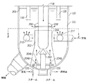
再生器120では(図2及び3参照)、スタンドパイプ118及びプラグバルブ200が存在する。使用済み触媒はスタンドパイプ118を流下し、触媒プラグバルブ200を通過する。プラグバルブ200を通過した後、触媒は、バルブ200の下の中心ウエル204中に配置された分配環204bへ、導管125から導入された流動化ガスを用いて方向を変え、使用済み触媒中心ウエル204の環状部分202を通り、上方へ流れる。流動化媒体又はガスは、例えば、スチーム、不活性ガス、及び燃料ガスにすることができる。スラリー油(導管126)及び流動化ガス(導管123)は、ノズル204aを通って導入される。流動化ガス、例えばスチームは、スラリー油が中心ウエル204中の触媒中に放出された時に、その分散及び噴霧を促進する。分散スチーム及びスラリー油は、高温使用済み触媒と接触して気化し、触媒のための付加的流動化を与える。この時点で、スラリー油の気化が必要である。酸素含有ガスは、中心ウエル204内で燃焼が起きないように、又は少なくともそれを最少にするため、ここでは流動化ガスとして用いないのが好ましい。触媒は、中心ウエル204の上端及び環状板208の外周により定められた環状スロット206から外側へ向けられて高密度相床122中へ入る。環状板208はスタンドパイプ118の回りに固定し、少なくとも中心ウエル204の外径と同じ外径を有するのが好ましい。このやり方で、触媒は放射状に外側へ分布されて高密度相触媒床122中へ、その上表面209より充分下へ入る。
In the regenerator 120 (see FIGS. 2 and 3), the
高密度流動化床122に、空気分配リング210の形態を取るのが好ましい空気グリッドにより与えられた空気を通す。リング210は、中心ウエル204の外径と、再生器120中の高密度相床122の外径との間の直径を有する。通気用空気は、有孔体又はノズル211から上方へ移動し、高密度相床122中へ入ると、スラリー油及び触媒上の炭素が燃焼してCO2を形成する。床122内で良好な燃焼を確実に行わせ、熱を発生させるためには、空気に比較的近接させて床122の上表面209の下へ高密度相床122中へスラリー油/触媒混合物を導入することが重要である。再生器120は1250〜1350°Fで操作されるのが典型的であり、好ましくは1275〜1325°Fである。リング210からの空気と、スロット206からの触媒/油混合物の合流物は高密度相床122内で比較的大きな速度をもち、床122内の燃焼領域で良好な混合を促進し、触媒の均一な加熱及び再生を与える。再生器床は、0.5〜7ft/秒、好ましくは1.5〜5ft/秒、一層好ましくは2〜3ft/秒の蒸気表面速度になるように設計されるべきである。空気リング210の上の床122の体積は、本質的に完全な触媒再生を確実に与えるのに、充分な残留時間を与えるように設計されるべきである。
The dense
再生器120から分離器サイクロン130及び塔頂導管212を通り、塔頂からオフガスが従来通り回収される(図1参照)。再生器120は完全燃焼方式で操作されるので、一般に大気中へ排出される前に、COをCO2へ転化するCO燃焼器は不必要であるが、もし望むならば、それを配備してもよい。完全燃焼が達成される場合、燃焼熱が一層多く発生するならば、必要な燃料油は少なくなる。一般に過剰の空気は用いないようにするが、実際問題として完全燃焼を達成するためには僅かに過剰である必要がある。
From the
再生器120は、COからCO2への転化を促進するために一般に添加されるCO促進剤、典型的には白金のような触媒を用い、又は用いずに操作することができる。
従来法の並列型の慣用的FCC再生器の下方部分が図4に示してある。触媒は傾斜(angled)パイプ414、触媒スライドバルブ416、及び入口420を通り再生器へ供給される。一対のハイドロクローン430の端部が、高密度床122の上表面209の下へ伸びている。燃焼空気は高密度床122中へ空気供給装置409により供給される。
The lower part of a conventional parallel conventional FCC regenerator is shown in FIG. Catalyst is supplied to the regenerator through an
図5に示した再生器400は、本発明によるものであり、並列型構成を持つFCC単位装置で有用であり、図4に示した再生器の代わりに置き換えることができる。新規な設置又は改装装置の一部分として、そのような再生器400は、従来の供給物又は軽質供給物を許容する一層大きな供給物融通性を与える。なぜなら、燃料油、急冷油、又はスラリー油供給能力が、必要な反応熱を与えるために軽質FCC供給物を処理した場合に与えられるからである。
The
図4に示したように、触媒供給のための傾斜パイプ414は、入口420の所では未だ終わっていない。むしろ傾斜パイプ414は、触媒スライドバルブ416を経て傾斜パイプ417へ結合されており、後者のパイプはそこから実質的に再生器400の垂直中心軸の方へ伸び、直立部分418を有し、そこから中心ウエル204の中へ伸びている。偏向板450がスタンド部分418の下端の下に配置されており、それによって触媒の流れを再び偏向する。同じ参照番号を有する残りの部品は、前の図の場合と同じである。
傾斜 As shown in FIG. 4, the
更に、慣用的再生器、例えば、図4に示した再生器を有する並列型構成のFCC単位装置は、図5に示した再生器400を有する変換FCC単位装置になるように変換し、新しい再生器を製造するのに伴われる資本コストを減少することができる。空気供給組立体460は取り除かれるであろう。中心ウエル204、流動化媒体分配リング204b、及び燃料分配ノズル204aは、中心ウエル204内の再生器の内部底に設置される。空気分配パイプ210を中心ウエル204の回り及び放射状スロット206の下に設置する。円状偏向板450を、中心ウエル204の中に設置する。スタンドパイプ部分418及び環状板208を有するパイプ417を、そのスタンドパイプ部分418の端が、偏向板450の上に充分な距離、中心ウエル204の中へ伸び、触媒の流れを可能にし、中心ウエル204中で気化する燃料油と触媒とを混合するために触媒の流れの方向を適切に偏向するように設置する。ハイドロクローン430は、再生器400内で置き換えるか、又は調整し直すか、又は再配置する必要があってもなくてもよく、それらの端部は高密度床122の上表面209より下に伸びている。
Further, a conventional regenerator, for example, an FCC unit in a parallel configuration having the regenerator shown in FIG. 4 is converted into a converted FCC unit having the regenerator 400 shown in FIG. The capital costs associated with manufacturing a vessel can be reduced. The air supply assembly 460 will be removed. The center well 204, the fluidizing
本発明を特定の態様に関連して上で例示してきた。それらを考慮して種々の変更及び修正が当業者には思い付くであろう。そのような修正は、全て特許請求の範囲の本質及び範囲内に入り、それらによって包含されるものである。 The invention has been illustrated above with reference to specific embodiments. Various changes and modifications will occur to those skilled in the art in light of the above. All such modifications fall within and are encompassed by the spirit and scope of the appended claims.
Claims (18)
(a) 急冷油インベントリーへ急冷油を供給し、前記インベントリーを定常状態に維持する工程、
(b) 前記流出物ガスを前記急冷油と接触させて前記流出物ガスを冷却し、触媒微粒物を洗浄除去し、微粒物を本質的に含まない冷却された流出物ガスを得る工程、
(c) 前記接触工程からの前記急冷油をインベントリーへ戻す工程、
(d) 前記インベントリーからの急冷油を前記接触工程へ連続的に再循環する工程、
(e) 前記インベントリーからの急冷油の流れから微粒物を連続的に分離し、微粒物を回収し、微粒物が前記インベントリー中に蓄積しないように維持する工程、及び
(f) 前記分離工程から回収された微粒物をスラリーにする工程、
を含む上記微粒物回収方法。 A method for recovering fine particulate matter from light FCC type effluent gas, comprising:
(A) supplying quenching oil to a quench oil inventory and maintaining said inventory in a steady state;
(B) contacting the effluent gas with the quench oil to cool the effluent gas, wash away catalyst particulates, and obtain a cooled effluent gas essentially free of particulates;
(C) returning the quenched oil from the contacting step to inventory.
(D) continuously recirculating the quench oil from the inventory to the contacting step;
(E) continuously separating fines from the quench oil stream from the inventory, collecting the fines, and maintaining the fines so that they do not accumulate in the inventory; and (f) from the separating step. A step of slurrying the collected fine particles,
The method for collecting fine particles described above.
流出物ガスを重油と連続的に接触させて流出物ガスを冷却し、そこに取り込まれていた微粒物を洗浄除去し、取り込まれた微粒物を本質的に含まない冷却された流出物ガスを得るための手段、
前記接触工程からの重油を液体受容器中に収集する手段、
前記液体受容器からの重油を、接触工程へ連続的に再循環する手段、
前記液体受容器からの重油を少なくとも一つのフィルターに通し、前記重油から微粒物を除去し、少なくとも一つのフィルターで前記微粒物を収集する手段、
少なくとも一つのフィルターを少なくとも周期的に逆洗浄して収集微粒物を除去する手段、及び
収集微粒物、及び第二重油、その重油の一部分、及びそれらの組合せから選択されたスラリー油を用いて、微粒物に富むスラリーを生成させる手段、
を含む上記微粒物回収装置。 An apparatus for recovering fine particles from light FCC type effluent gas,
The effluent gas is continuously contacted with heavy oil to cool the effluent gas, wash away fines trapped therein, and remove the cooled effluent gas essentially free of the trapped fines. Means to obtain,
Means for collecting the heavy oil from the contacting step in a liquid receiver;
Means for continuously recirculating heavy oil from the liquid receiver to the contacting step,
Means for passing heavy oil from the liquid receiver through at least one filter, removing fines from the heavy oil, and collecting the fines with at least one filter;
Means for at least periodically backwashing at least one filter to remove collected particulates; andusing the collected particulates and a slurry oil selected from a second oil, a portion of the heavy oil, and combinations thereof, Means for producing a slurry rich in fine particles,
The above-mentioned fine particle collection device comprising:
流出物ガスを受けるための入口、前記流出物ガスを冷却し、前記微粒物を洗浄除去するための、前記入口の上に配置された気・液接触部材、取り込まれた微粒物を本質的に含まない冷却流出物ガスを排出するための、前記接触部材より上にあるガス出口、及び前記接触部材から急冷油を収集するための、前記入口の下にある液体保持領域、を有する急冷塔、
前記液体保持領域から前記接触部材へ急冷油を連続的に再循環するための再循環経路、
交互に濾過方式と逆洗浄方式とで操作することができる少なくとも二つのフィルター、
前記液体保持領域から急冷油を、濾過方式のフィルターに通して循環させ、濾液を前記液体保持領域へ戻す濾過経路、及び
圧縮ガスを逆洗浄方式のフィルターに通し、そこからの微粒物をスラリー収集領域へ導入する逆洗浄経路、
を含む上記微粒物回収装置。 An apparatus for recovering fine particles from light FCC type effluent gas,
An inlet for receiving the effluent gas, a gas-liquid contact member disposed above the inlet for cooling the effluent gas and washing and removing the fines, essentially removing the entrapped fines; A quench tower having a gas outlet above the contact member for discharging the cooling effluent gas free, and a liquid holding area below the inlet for collecting quench oil from the contact member;
A recirculation path for continuously recirculating quenching oil from the liquid holding area to the contact member,
At least two filters, which can be operated alternately in a filtration mode and a backwash mode,
The quenched oil from the liquid holding area is circulated through a filter of a filtration system, a filtration path for returning the filtrate to the liquid holding area, and a compressed gas is passed through a filter of a back washing type, and fine particles therefrom are collected as slurry Backwash route to be introduced into the area,
The above-mentioned fine particle collection device comprising:
Applications Claiming Priority (1)
| Application Number | Priority Date | Filing Date | Title |
|---|---|---|---|
| US10/065,377 US7011740B2 (en) | 2002-10-10 | 2002-10-10 | Catalyst recovery from light olefin FCC effluent |
Publications (2)
| Publication Number | Publication Date |
|---|---|
| JP2004131736A true JP2004131736A (en) | 2004-04-30 |
| JP4351019B2 JP4351019B2 (en) | 2009-10-28 |
Family
ID=32067692
Family Applications (1)
| Application Number | Title | Priority Date | Filing Date |
|---|---|---|---|
| JP2003350226A Expired - Lifetime JP4351019B2 (en) | 2002-10-10 | 2003-10-09 | Catalyst recovery from light olefin FCC effluent |
Country Status (10)
| Country | Link |
|---|---|
| US (1) | US7011740B2 (en) |
| EP (2) | EP1413621B1 (en) |
| JP (1) | JP4351019B2 (en) |
| CN (1) | CN100537715C (en) |
| CA (1) | CA2437651C (en) |
| DE (1) | DE60333334D1 (en) |
| ES (1) | ES2345042T3 (en) |
| MX (1) | MXPA03009298A (en) |
| RU (1) | RU2330059C2 (en) |
| SG (1) | SG111144A1 (en) |
Cited By (4)
| Publication number | Priority date | Publication date | Assignee | Title |
|---|---|---|---|---|
| JP2008260713A (en) * | 2007-04-12 | 2008-10-30 | Sumitomo Chemical Co Ltd | Filtration method |
| KR20190119637A (en) * | 2017-02-28 | 2019-10-22 | 부르크하르트 콤프레션 아게 | Apparatus and method for separating lubricant from gas streams and systems and methods for compressing flammable gases |
| KR20200078012A (en) * | 2018-12-21 | 2020-07-01 | 한국기계연구원 | Fluidized bed catalyst regenerator |
| US11279885B2 (en) | 2018-05-10 | 2022-03-22 | Korea Institute Of Machinery & Materials | Catalyst regenerator |
Families Citing this family (50)
| Publication number | Priority date | Publication date | Assignee | Title |
|---|---|---|---|---|
| US7329790B2 (en) * | 2004-04-15 | 2008-02-12 | Uop Llc | Wet scrubbing and recycle of effluent-contaminating catalyst particles in an oxygenate-to-olefin process |
| CN1325607C (en) * | 2005-12-07 | 2007-07-11 | 江苏工业学院 | Filter device for reaction system of petroleum catalytic cracking experiment apparatus |
| CN100386127C (en) * | 2006-03-24 | 2008-05-07 | 天津大学 | Coke arresting device at the bottom of the vacuum tower and its application |
| US7572364B2 (en) * | 2006-04-27 | 2009-08-11 | Intercat Equipment, Inc. | Fluid catalytic cracking system with fines addition system |
| US7491315B2 (en) * | 2006-08-11 | 2009-02-17 | Kellogg Brown & Root Llc | Dual riser FCC reactor process with light and mixed light/heavy feeds |
| EP2082010A4 (en) * | 2006-09-28 | 2014-12-03 | Uop Llc | Process for enhanced olefin production |
| US7687677B1 (en) | 2006-09-29 | 2010-03-30 | Uop Llc | Process for recovering thermal energy from a reactor effluent stream |
| US7611622B2 (en) | 2006-12-29 | 2009-11-03 | Kellogg Brown & Root Llc | FCC process for converting C3/C4 feeds to olefins and aromatics |
| US8608942B2 (en) * | 2007-03-15 | 2013-12-17 | Kellogg Brown & Root Llc | Systems and methods for residue upgrading |
| US8044254B2 (en) * | 2007-09-27 | 2011-10-25 | Uop Llc | Process for enhanced olefin production |
| US8137535B2 (en) * | 2008-01-29 | 2012-03-20 | Kellogg Brown & Root Llc | Method for adjusting catalyst activity |
| US7883618B2 (en) * | 2008-02-28 | 2011-02-08 | Kellogg Brown & Root Llc | Recycle of olefinic naphthas by removing aromatics |
| US8735642B2 (en) * | 2008-06-30 | 2014-05-27 | Uop Llc | Two stage contact cooler design for hot water generation |
| US8618012B2 (en) | 2010-04-09 | 2013-12-31 | Kellogg Brown & Root Llc | Systems and methods for regenerating a spent catalyst |
| US8618011B2 (en) | 2010-04-09 | 2013-12-31 | Kellogg Brown & Root Llc | Systems and methods for regenerating a spent catalyst |
| US8383052B2 (en) * | 2010-04-16 | 2013-02-26 | Kellogg Brown & Root Llc | System for a heat balanced FCC forlight hydrocarbon feeds |
| US8506795B2 (en) | 2010-06-04 | 2013-08-13 | Uop Llc | Process for fluid catalytic cracking |
| CN102002385B (en) * | 2010-12-07 | 2014-08-06 | 上海蓝科石化工程技术有限公司 | Device and method for separating residue from catalytic cracking oil slurry |
| US8877997B2 (en) * | 2010-12-20 | 2014-11-04 | Uop Llc | Quench tower catalyst recovery |
| US8889942B2 (en) | 2010-12-23 | 2014-11-18 | Kellogg Brown & Root Llc | Integrated light olefin separation/cracking process |
| US8815082B2 (en) | 2011-12-12 | 2014-08-26 | Uop Llc | Process and apparatus for mixing two streams of catalyst |
| US8747758B2 (en) | 2011-12-12 | 2014-06-10 | Uop Llc | Process and apparatus for mixing two streams of catalyst |
| US8747759B2 (en) | 2011-12-12 | 2014-06-10 | Uop Llc | Process and apparatus for mixing two streams of catalyst |
| US8747657B2 (en) | 2011-12-12 | 2014-06-10 | Uop Llc | Process and apparatus for mixing two streams of catalyst |
| US8932452B2 (en) | 2012-01-11 | 2015-01-13 | Cameron International Corporation | Method for separating entrained catalyst and catalyst fines from slurry oil |
| US9446364B2 (en) * | 2012-02-23 | 2016-09-20 | Kellogg Brown & Root Llc | Surge drum mixing system |
| US8916099B2 (en) | 2012-03-20 | 2014-12-23 | Uop Llc | Process and apparatus for mixing two streams of catalyst |
| US8936758B2 (en) | 2012-03-20 | 2015-01-20 | Uop Llc | Process and apparatus for mixing two streams of catalyst |
| US9375695B2 (en) | 2012-03-20 | 2016-06-28 | Uop Llc | Process and apparatus for mixing two streams of catalyst |
| US8815166B2 (en) | 2012-03-20 | 2014-08-26 | Uop Llc | Process and apparatus for mixing two streams of catalyst |
| DE102012006992A1 (en) * | 2012-04-05 | 2013-10-10 | Linde Aktiengesellschaft | Process for the separation of olefins with mild cleavage |
| US9745519B2 (en) | 2012-08-22 | 2017-08-29 | Kellogg Brown & Root Llc | FCC process using a modified catalyst |
| US9205394B2 (en) | 2014-03-31 | 2015-12-08 | Uop Llc | Process and apparatus for distributing fluidizing gas to an FCC riser |
| US9376633B2 (en) | 2014-03-31 | 2016-06-28 | Uop Llc | Process and apparatus for distributing fluidizing gas to an FCC riser |
| WO2016053780A1 (en) | 2014-09-29 | 2016-04-07 | Uop Llc | Methods for reducing flue gas emissions from fluid catalytic cracking unit regenerators |
| AR111992A1 (en) | 2017-06-19 | 2019-09-11 | Dow Global Technologies Llc | REACTOR SYSTEMS THAT INCLUDE THE RECYCLING OF FLUIDS |
| CN107597201B (en) * | 2017-09-13 | 2019-10-08 | 上海华畅环保设备发展有限公司 | Oil-containing outlet catalyst treatment and sorting reuse method and device |
| CN108061297B (en) * | 2017-11-21 | 2019-05-14 | 中国能源建设集团华东电力试验研究院有限公司 | 300MW circulating fluidized bed boiler and its control method |
| KR102740707B1 (en) * | 2018-05-23 | 2024-12-11 | 켈로그 브라운 앤드 루트 엘엘씨 | Regulatory controller for use in catalytic olefin units |
| CN112166171B (en) * | 2018-05-23 | 2023-01-31 | 凯洛格·布朗及鲁特有限公司 | Conditioning controller for a catalytic olefin unit |
| US11118117B2 (en) | 2019-05-23 | 2021-09-14 | Kellogg Brown & Root Llc | Regulatory controller for usage in a catalytic olefins |
| CN109647544B (en) * | 2019-01-03 | 2021-06-11 | 飞潮(无锡)过滤技术有限公司 | Process for recovering waste copper bismuth catalyst by dry-wet composite regeneration |
| US20220250049A1 (en) * | 2019-03-21 | 2022-08-11 | Kellogg Brown & Root Llc | Processes for catalytic paraffin dehydrogenation and catalyst recovery |
| WO2020191192A1 (en) * | 2019-03-21 | 2020-09-24 | Kellogg Brown & Root Llc | Processes for catalytic paraffin dehydrogenation and catalyst recovery |
| CN113646286A (en) * | 2019-03-21 | 2021-11-12 | 凯洛格·布朗及鲁特有限公司 | Systems and methods for removing catalyst from MTO effluent |
| US11117108B2 (en) * | 2019-09-13 | 2021-09-14 | Kellogg Brown & Root Llc | Use of a fuel oil wash to remove catalyst from a fluidized-bed propane dehydrogenation reactor effluent |
| US11725153B2 (en) * | 2020-04-17 | 2023-08-15 | Uop Llc | Process and apparatus for recovering catalyst from a product stream |
| CN114433250A (en) * | 2020-10-16 | 2022-05-06 | 中国石油化工股份有限公司 | Slurry recovery device, slurry preparation system, and slurry recovery method |
| US20230133426A1 (en) * | 2021-11-02 | 2023-05-04 | Uop Llc | Process and apparatus for reacting feed with cooled regenerated catalyst |
| WO2023212497A1 (en) * | 2022-04-25 | 2023-11-02 | Kellogg Brown & Root Llc | Processes for catalytic paraffin dehydrogenation and catalyst recovery |
Family Cites Families (19)
| Publication number | Priority date | Publication date | Assignee | Title |
|---|---|---|---|---|
| US2663676A (en) * | 1951-03-16 | 1953-12-22 | Standard Oil Dev Co | Catalyst recovery |
| DE1180361B (en) * | 1959-12-22 | 1964-10-29 | Basf Ag | Process for regulating the grain size distribution in the autothermal splitting of hydrocarbons in a fluidized bed of solids |
| BE601348A (en) * | 1960-03-16 | |||
| US3338821A (en) * | 1964-11-18 | 1967-08-29 | Phillips Petroleum Co | Quenching of catalytic cracking reactor vapors in feed line to fractionator |
| US4285805A (en) * | 1980-03-20 | 1981-08-25 | Phillips Petroleum Company | Time-delay process and control system for electrostatic filter |
| US5167795A (en) * | 1988-01-28 | 1992-12-01 | Stone & Webster Engineering Corp. | Process for the production of olefins and aromatics |
| US5271826A (en) * | 1988-03-03 | 1993-12-21 | Mobil Oil Corporation | Catalytic cracking of coke producing hydrocarbons |
| US5234578A (en) * | 1988-08-26 | 1993-08-10 | Uop | Fluidized catalytic cracking process utilizing a high temperature reactor |
| US5043522A (en) * | 1989-04-25 | 1991-08-27 | Arco Chemical Technology, Inc. | Production of olefins from a mixture of Cu+ olefins and paraffins |
| US5073249A (en) * | 1989-11-21 | 1991-12-17 | Mobil Oil Corporation | Heavy oil catalytic cracking process and apparatus |
| US5171921A (en) * | 1991-04-26 | 1992-12-15 | Arco Chemical Technology, L.P. | Production of olefins |
| US5220093A (en) * | 1992-04-03 | 1993-06-15 | Stone & Webster Engineering Corporation | Process for production of olefins from mixtures of light paraffins |
| CN1089641A (en) * | 1992-08-20 | 1994-07-20 | 史东及韦伯斯特工程公司 | The catalyst cracking method that contains the paraffin-rich feedstock of high and low Kang Laxun carbon residue component |
| US5346613A (en) * | 1993-09-24 | 1994-09-13 | Uop | FCC process with total catalyst blending |
| US5858207A (en) * | 1997-12-05 | 1999-01-12 | Uop Llc | FCC process with combined regenerator stripper and catalyst blending |
| US5965012A (en) * | 1997-12-05 | 1999-10-12 | Uop Llc | FCC process with short primary contacting and controlled secondary contacting |
| US6118035A (en) | 1998-05-05 | 2000-09-12 | Exxon Research And Engineering Co. | Process for selectively producing light olefins in a fluid catalytic cracking process from a naphtha/steam feed |
| US6113776A (en) * | 1998-06-08 | 2000-09-05 | Uop Llc | FCC process with high temperature cracking zone |
| US6139720A (en) * | 1999-02-19 | 2000-10-31 | Uop Llc | FCC process with carbon monoxide management and hot stripping |
-
2002
- 2002-10-10 US US10/065,377 patent/US7011740B2/en not_active Expired - Lifetime
-
2003
- 2003-08-20 CA CA2437651A patent/CA2437651C/en not_active Expired - Fee Related
- 2003-08-28 SG SG200304859A patent/SG111144A1/en unknown
- 2003-09-25 EP EP03021732A patent/EP1413621B1/en not_active Expired - Lifetime
- 2003-09-25 EP EP09175966.2A patent/EP2161322B1/en not_active Expired - Lifetime
- 2003-09-25 ES ES03021732T patent/ES2345042T3/en not_active Expired - Lifetime
- 2003-09-25 DE DE60333334T patent/DE60333334D1/en not_active Expired - Lifetime
- 2003-10-09 JP JP2003350226A patent/JP4351019B2/en not_active Expired - Lifetime
- 2003-10-09 RU RU2003129991/04A patent/RU2330059C2/en active
- 2003-10-10 MX MXPA03009298A patent/MXPA03009298A/en active IP Right Grant
- 2003-10-10 CN CNB2003101006420A patent/CN100537715C/en not_active Expired - Lifetime
Cited By (6)
| Publication number | Priority date | Publication date | Assignee | Title |
|---|---|---|---|---|
| JP2008260713A (en) * | 2007-04-12 | 2008-10-30 | Sumitomo Chemical Co Ltd | Filtration method |
| KR20190119637A (en) * | 2017-02-28 | 2019-10-22 | 부르크하르트 콤프레션 아게 | Apparatus and method for separating lubricant from gas streams and systems and methods for compressing flammable gases |
| KR102549756B1 (en) | 2017-02-28 | 2023-06-29 | 부르크하르트 콤프레션 아게 | Apparatus and method for separating lubricants from gas streams and systems and methods for compressing combustible gases |
| US11279885B2 (en) | 2018-05-10 | 2022-03-22 | Korea Institute Of Machinery & Materials | Catalyst regenerator |
| KR20200078012A (en) * | 2018-12-21 | 2020-07-01 | 한국기계연구원 | Fluidized bed catalyst regenerator |
| KR102232804B1 (en) | 2018-12-21 | 2021-03-26 | 한국기계연구원 | Fluidized bed catalyst regenerator |
Also Published As
| Publication number | Publication date |
|---|---|
| EP2161322B1 (en) | 2014-08-27 |
| EP1413621B1 (en) | 2010-07-14 |
| JP4351019B2 (en) | 2009-10-28 |
| CA2437651A1 (en) | 2004-04-10 |
| MXPA03009298A (en) | 2004-04-28 |
| ES2345042T3 (en) | 2010-09-14 |
| CA2437651C (en) | 2013-02-19 |
| SG111144A1 (en) | 2005-05-30 |
| DE60333334D1 (en) | 2010-08-26 |
| EP2161322A1 (en) | 2010-03-10 |
| CN100537715C (en) | 2009-09-09 |
| EP1413621A1 (en) | 2004-04-28 |
| US7011740B2 (en) | 2006-03-14 |
| US20040069684A1 (en) | 2004-04-15 |
| CN1497040A (en) | 2004-05-19 |
| RU2330059C2 (en) | 2008-07-27 |
| RU2003129991A (en) | 2005-03-27 |
Similar Documents
| Publication | Publication Date | Title |
|---|---|---|
| JP4351019B2 (en) | Catalyst recovery from light olefin FCC effluent | |
| JP4284146B2 (en) | Catalyst regenerator with a central well | |
| US7026262B1 (en) | Apparatus and process for regenerating catalyst | |
| EP0848051B1 (en) | Fluid catalytic cracking of hydrocarbons with integrated apparatus for separating and stripping catalyst | |
| JP2523325B2 (en) | Novel downflow fluidized catalytic cracking reactor | |
| US5582712A (en) | Downflow FCC reaction arrangement with upflow regeneration | |
| CN1263829C (en) | Stripping process and apparatus | |
| US20030047437A1 (en) | Process for the conversion of waste plastics to produce hydrocarbon oils | |
| US6039863A (en) | Fluidized particle contacting process with elongated combustor | |
| RU2079541C1 (en) | Method and apparatus for conducting catalytic cracking of raw material in fluidized bed | |
| US3846280A (en) | Method of improving a dense fluid bed catalyst regenerator used in conjunction with a riser hydrocarbon conversion operation | |
| JP6860675B2 (en) | Processes and equipment for improved removal of contaminants in fluid cracking processes | |
| JPH0321695A (en) | Fluid cat cracking of hydro- carbon feedstock using mixture capable of separating catalyst from adsorbent and its device | |
| US4428822A (en) | Fluid catalytic cracking | |
| EP0309244B1 (en) | Fluid catalytic cracking regeneration with spent catalyst separator | |
| EP0490453A1 (en) | Process and apparatus for removal of carbonaceous materials from particles containing such materials | |
| RU2411284C2 (en) | Device and method for catalyst regeneration | |
| AU724751B2 (en) | Fluid catalytic cracking of hydrocarbons with integrated apparatus for separating and stripping catalyst | |
| EP0078797A1 (en) | A combination process for upgrading residual oils | |
| TWI414359B (en) | Apparatus and process for regenerating catalyst |
Legal Events
| Date | Code | Title | Description |
|---|---|---|---|
| A621 | Written request for application examination |
Free format text: JAPANESE INTERMEDIATE CODE: A621 Effective date: 20060510 |
|
| A131 | Notification of reasons for refusal |
Free format text: JAPANESE INTERMEDIATE CODE: A131 Effective date: 20081010 |
|
| RD04 | Notification of resignation of power of attorney |
Free format text: JAPANESE INTERMEDIATE CODE: A7424 Effective date: 20081015 |
|
| A601 | Written request for extension of time |
Free format text: JAPANESE INTERMEDIATE CODE: A601 Effective date: 20090113 |
|
| A602 | Written permission of extension of time |
Free format text: JAPANESE INTERMEDIATE CODE: A602 Effective date: 20090116 |
|
| A521 | Request for written amendment filed |
Free format text: JAPANESE INTERMEDIATE CODE: A523 Effective date: 20090210 |
|
| A131 | Notification of reasons for refusal |
Free format text: JAPANESE INTERMEDIATE CODE: A131 Effective date: 20090313 |
|
| A521 | Request for written amendment filed |
Free format text: JAPANESE INTERMEDIATE CODE: A523 Effective date: 20090611 |
|
| TRDD | Decision of grant or rejection written | ||
| A01 | Written decision to grant a patent or to grant a registration (utility model) |
Free format text: JAPANESE INTERMEDIATE CODE: A01 Effective date: 20090703 |
|
| A01 | Written decision to grant a patent or to grant a registration (utility model) |
Free format text: JAPANESE INTERMEDIATE CODE: A01 |
|
| A61 | First payment of annual fees (during grant procedure) |
Free format text: JAPANESE INTERMEDIATE CODE: A61 Effective date: 20090723 |
|
| FPAY | Renewal fee payment (event date is renewal date of database) |
Free format text: PAYMENT UNTIL: 20120731 Year of fee payment: 3 |
|
| R150 | Certificate of patent or registration of utility model |
Ref document number: 4351019 Country of ref document: JP Free format text: JAPANESE INTERMEDIATE CODE: R150 Free format text: JAPANESE INTERMEDIATE CODE: R150 |
|
| FPAY | Renewal fee payment (event date is renewal date of database) |
Free format text: PAYMENT UNTIL: 20130731 Year of fee payment: 4 |
|
| R250 | Receipt of annual fees |
Free format text: JAPANESE INTERMEDIATE CODE: R250 |
|
| R250 | Receipt of annual fees |
Free format text: JAPANESE INTERMEDIATE CODE: R250 |
|
| R250 | Receipt of annual fees |
Free format text: JAPANESE INTERMEDIATE CODE: R250 |
|
| R250 | Receipt of annual fees |
Free format text: JAPANESE INTERMEDIATE CODE: R250 |
|
| R250 | Receipt of annual fees |
Free format text: JAPANESE INTERMEDIATE CODE: R250 |
|
| R250 | Receipt of annual fees |
Free format text: JAPANESE INTERMEDIATE CODE: R250 |
|
| R250 | Receipt of annual fees |
Free format text: JAPANESE INTERMEDIATE CODE: R250 |
|
| R250 | Receipt of annual fees |
Free format text: JAPANESE INTERMEDIATE CODE: R250 |
|
| R250 | Receipt of annual fees |
Free format text: JAPANESE INTERMEDIATE CODE: R250 |
|
| R250 | Receipt of annual fees |
Free format text: JAPANESE INTERMEDIATE CODE: R250 |
|
| R250 | Receipt of annual fees |
Free format text: JAPANESE INTERMEDIATE CODE: R250 |
|
| R250 | Receipt of annual fees |
Free format text: JAPANESE INTERMEDIATE CODE: R250 |
|
| EXPY | Cancellation because of completion of term |