EP4259231B1 - Manifold assembly for a peritoneal dialysis apparatus and peritoneal dialysis apparatus comprising said manifold assembly - Google Patents
Manifold assembly for a peritoneal dialysis apparatus and peritoneal dialysis apparatus comprising said manifold assembly Download PDFInfo
- Publication number
- EP4259231B1 EP4259231B1 EP21831296.5A EP21831296A EP4259231B1 EP 4259231 B1 EP4259231 B1 EP 4259231B1 EP 21831296 A EP21831296 A EP 21831296A EP 4259231 B1 EP4259231 B1 EP 4259231B1
- Authority
- EP
- European Patent Office
- Prior art keywords
- casing
- compartment
- assembly
- pump
- valve
- Prior art date
- Legal status (The legal status is an assumption and is not a legal conclusion. Google has not performed a legal analysis and makes no representation as to the accuracy of the status listed.)
- Active
Links
Images


Classifications
-
- A—HUMAN NECESSITIES
- A61—MEDICAL OR VETERINARY SCIENCE; HYGIENE
- A61M—DEVICES FOR INTRODUCING MEDIA INTO, OR ONTO, THE BODY; DEVICES FOR TRANSDUCING BODY MEDIA OR FOR TAKING MEDIA FROM THE BODY; DEVICES FOR PRODUCING OR ENDING SLEEP OR STUPOR
- A61M1/00—Suction or pumping devices for medical purposes; Devices for carrying-off, for treatment of, or for carrying-over, body-liquids; Drainage systems
- A61M1/14—Dialysis systems; Artificial kidneys; Blood oxygenators ; Reciprocating systems for treatment of body fluids, e.g. single needle systems for hemofiltration or pheresis
- A61M1/28—Peritoneal dialysis ; Other peritoneal treatment, e.g. oxygenation
- A61M1/281—Instillation other than by gravity
-
- A—HUMAN NECESSITIES
- A61—MEDICAL OR VETERINARY SCIENCE; HYGIENE
- A61M—DEVICES FOR INTRODUCING MEDIA INTO, OR ONTO, THE BODY; DEVICES FOR TRANSDUCING BODY MEDIA OR FOR TAKING MEDIA FROM THE BODY; DEVICES FOR PRODUCING OR ENDING SLEEP OR STUPOR
- A61M1/00—Suction or pumping devices for medical purposes; Devices for carrying-off, for treatment of, or for carrying-over, body-liquids; Drainage systems
- A61M1/14—Dialysis systems; Artificial kidneys; Blood oxygenators ; Reciprocating systems for treatment of body fluids, e.g. single needle systems for hemofiltration or pheresis
- A61M1/15—Dialysis systems; Artificial kidneys; Blood oxygenators ; Reciprocating systems for treatment of body fluids, e.g. single needle systems for hemofiltration or pheresis with a cassette forming partially or totally the flow circuit for the treating fluid, e.g. the dialysate fluid circuit or the treating gas circuit
- A61M1/152—Details related to the interface between cassette and machine
- A61M1/1524—Details related to the interface between cassette and machine the interface providing means for actuating on functional elements of the cassette, e.g. plungers
-
- A—HUMAN NECESSITIES
- A61—MEDICAL OR VETERINARY SCIENCE; HYGIENE
- A61M—DEVICES FOR INTRODUCING MEDIA INTO, OR ONTO, THE BODY; DEVICES FOR TRANSDUCING BODY MEDIA OR FOR TAKING MEDIA FROM THE BODY; DEVICES FOR PRODUCING OR ENDING SLEEP OR STUPOR
- A61M1/00—Suction or pumping devices for medical purposes; Devices for carrying-off, for treatment of, or for carrying-over, body-liquids; Drainage systems
- A61M1/14—Dialysis systems; Artificial kidneys; Blood oxygenators ; Reciprocating systems for treatment of body fluids, e.g. single needle systems for hemofiltration or pheresis
- A61M1/15—Dialysis systems; Artificial kidneys; Blood oxygenators ; Reciprocating systems for treatment of body fluids, e.g. single needle systems for hemofiltration or pheresis with a cassette forming partially or totally the flow circuit for the treating fluid, e.g. the dialysate fluid circuit or the treating gas circuit
- A61M1/153—Dialysis systems; Artificial kidneys; Blood oxygenators ; Reciprocating systems for treatment of body fluids, e.g. single needle systems for hemofiltration or pheresis with a cassette forming partially or totally the flow circuit for the treating fluid, e.g. the dialysate fluid circuit or the treating gas circuit the cassette being adapted for heating or cooling the treating fluid, e.g. the dialysate or the treating gas
-
- A—HUMAN NECESSITIES
- A61—MEDICAL OR VETERINARY SCIENCE; HYGIENE
- A61M—DEVICES FOR INTRODUCING MEDIA INTO, OR ONTO, THE BODY; DEVICES FOR TRANSDUCING BODY MEDIA OR FOR TAKING MEDIA FROM THE BODY; DEVICES FOR PRODUCING OR ENDING SLEEP OR STUPOR
- A61M1/00—Suction or pumping devices for medical purposes; Devices for carrying-off, for treatment of, or for carrying-over, body-liquids; Drainage systems
- A61M1/14—Dialysis systems; Artificial kidneys; Blood oxygenators ; Reciprocating systems for treatment of body fluids, e.g. single needle systems for hemofiltration or pheresis
- A61M1/15—Dialysis systems; Artificial kidneys; Blood oxygenators ; Reciprocating systems for treatment of body fluids, e.g. single needle systems for hemofiltration or pheresis with a cassette forming partially or totally the flow circuit for the treating fluid, e.g. the dialysate fluid circuit or the treating gas circuit
- A61M1/154—Dialysis systems; Artificial kidneys; Blood oxygenators ; Reciprocating systems for treatment of body fluids, e.g. single needle systems for hemofiltration or pheresis with a cassette forming partially or totally the flow circuit for the treating fluid, e.g. the dialysate fluid circuit or the treating gas circuit with sensing means or components thereof
-
- A—HUMAN NECESSITIES
- A61—MEDICAL OR VETERINARY SCIENCE; HYGIENE
- A61M—DEVICES FOR INTRODUCING MEDIA INTO, OR ONTO, THE BODY; DEVICES FOR TRANSDUCING BODY MEDIA OR FOR TAKING MEDIA FROM THE BODY; DEVICES FOR PRODUCING OR ENDING SLEEP OR STUPOR
- A61M1/00—Suction or pumping devices for medical purposes; Devices for carrying-off, for treatment of, or for carrying-over, body-liquids; Drainage systems
- A61M1/14—Dialysis systems; Artificial kidneys; Blood oxygenators ; Reciprocating systems for treatment of body fluids, e.g. single needle systems for hemofiltration or pheresis
- A61M1/15—Dialysis systems; Artificial kidneys; Blood oxygenators ; Reciprocating systems for treatment of body fluids, e.g. single needle systems for hemofiltration or pheresis with a cassette forming partially or totally the flow circuit for the treating fluid, e.g. the dialysate fluid circuit or the treating gas circuit
- A61M1/155—Dialysis systems; Artificial kidneys; Blood oxygenators ; Reciprocating systems for treatment of body fluids, e.g. single needle systems for hemofiltration or pheresis with a cassette forming partially or totally the flow circuit for the treating fluid, e.g. the dialysate fluid circuit or the treating gas circuit with treatment-fluid pumping means or components thereof
-
- A—HUMAN NECESSITIES
- A61—MEDICAL OR VETERINARY SCIENCE; HYGIENE
- A61M—DEVICES FOR INTRODUCING MEDIA INTO, OR ONTO, THE BODY; DEVICES FOR TRANSDUCING BODY MEDIA OR FOR TAKING MEDIA FROM THE BODY; DEVICES FOR PRODUCING OR ENDING SLEEP OR STUPOR
- A61M1/00—Suction or pumping devices for medical purposes; Devices for carrying-off, for treatment of, or for carrying-over, body-liquids; Drainage systems
- A61M1/14—Dialysis systems; Artificial kidneys; Blood oxygenators ; Reciprocating systems for treatment of body fluids, e.g. single needle systems for hemofiltration or pheresis
- A61M1/15—Dialysis systems; Artificial kidneys; Blood oxygenators ; Reciprocating systems for treatment of body fluids, e.g. single needle systems for hemofiltration or pheresis with a cassette forming partially or totally the flow circuit for the treating fluid, e.g. the dialysate fluid circuit or the treating gas circuit
- A61M1/156—Constructional details of the cassette, e.g. specific details on material or shape
- A61M1/1561—Constructional details of the cassette, e.g. specific details on material or shape at least one cassette surface or portion thereof being flexible, e.g. the cassette having a rigid base portion with preformed channels and being covered with a foil
-
- A—HUMAN NECESSITIES
- A61—MEDICAL OR VETERINARY SCIENCE; HYGIENE
- A61M—DEVICES FOR INTRODUCING MEDIA INTO, OR ONTO, THE BODY; DEVICES FOR TRANSDUCING BODY MEDIA OR FOR TAKING MEDIA FROM THE BODY; DEVICES FOR PRODUCING OR ENDING SLEEP OR STUPOR
- A61M1/00—Suction or pumping devices for medical purposes; Devices for carrying-off, for treatment of, or for carrying-over, body-liquids; Drainage systems
- A61M1/14—Dialysis systems; Artificial kidneys; Blood oxygenators ; Reciprocating systems for treatment of body fluids, e.g. single needle systems for hemofiltration or pheresis
- A61M1/15—Dialysis systems; Artificial kidneys; Blood oxygenators ; Reciprocating systems for treatment of body fluids, e.g. single needle systems for hemofiltration or pheresis with a cassette forming partially or totally the flow circuit for the treating fluid, e.g. the dialysate fluid circuit or the treating gas circuit
- A61M1/156—Constructional details of the cassette, e.g. specific details on material or shape
- A61M1/1563—Details of incorporated filters
-
- A—HUMAN NECESSITIES
- A61—MEDICAL OR VETERINARY SCIENCE; HYGIENE
- A61M—DEVICES FOR INTRODUCING MEDIA INTO, OR ONTO, THE BODY; DEVICES FOR TRANSDUCING BODY MEDIA OR FOR TAKING MEDIA FROM THE BODY; DEVICES FOR PRODUCING OR ENDING SLEEP OR STUPOR
- A61M1/00—Suction or pumping devices for medical purposes; Devices for carrying-off, for treatment of, or for carrying-over, body-liquids; Drainage systems
- A61M1/14—Dialysis systems; Artificial kidneys; Blood oxygenators ; Reciprocating systems for treatment of body fluids, e.g. single needle systems for hemofiltration or pheresis
- A61M1/28—Peritoneal dialysis ; Other peritoneal treatment, e.g. oxygenation
- A61M1/282—Operational modes
-
- A—HUMAN NECESSITIES
- A61—MEDICAL OR VETERINARY SCIENCE; HYGIENE
- A61M—DEVICES FOR INTRODUCING MEDIA INTO, OR ONTO, THE BODY; DEVICES FOR TRANSDUCING BODY MEDIA OR FOR TAKING MEDIA FROM THE BODY; DEVICES FOR PRODUCING OR ENDING SLEEP OR STUPOR
- A61M1/00—Suction or pumping devices for medical purposes; Devices for carrying-off, for treatment of, or for carrying-over, body-liquids; Drainage systems
- A61M1/14—Dialysis systems; Artificial kidneys; Blood oxygenators ; Reciprocating systems for treatment of body fluids, e.g. single needle systems for hemofiltration or pheresis
- A61M1/28—Peritoneal dialysis ; Other peritoneal treatment, e.g. oxygenation
- A61M1/288—Priming
-
- A—HUMAN NECESSITIES
- A61—MEDICAL OR VETERINARY SCIENCE; HYGIENE
- A61M—DEVICES FOR INTRODUCING MEDIA INTO, OR ONTO, THE BODY; DEVICES FOR TRANSDUCING BODY MEDIA OR FOR TAKING MEDIA FROM THE BODY; DEVICES FOR PRODUCING OR ENDING SLEEP OR STUPOR
- A61M2205/00—General characteristics of the apparatus
- A61M2205/12—General characteristics of the apparatus with interchangeable cassettes forming partially or totally the fluid circuit
- A61M2205/121—General characteristics of the apparatus with interchangeable cassettes forming partially or totally the fluid circuit interface between cassette and base
-
- A—HUMAN NECESSITIES
- A61—MEDICAL OR VETERINARY SCIENCE; HYGIENE
- A61M—DEVICES FOR INTRODUCING MEDIA INTO, OR ONTO, THE BODY; DEVICES FOR TRANSDUCING BODY MEDIA OR FOR TAKING MEDIA FROM THE BODY; DEVICES FOR PRODUCING OR ENDING SLEEP OR STUPOR
- A61M2205/00—General characteristics of the apparatus
- A61M2205/12—General characteristics of the apparatus with interchangeable cassettes forming partially or totally the fluid circuit
- A61M2205/123—General characteristics of the apparatus with interchangeable cassettes forming partially or totally the fluid circuit with incorporated reservoirs
-
- A—HUMAN NECESSITIES
- A61—MEDICAL OR VETERINARY SCIENCE; HYGIENE
- A61M—DEVICES FOR INTRODUCING MEDIA INTO, OR ONTO, THE BODY; DEVICES FOR TRANSDUCING BODY MEDIA OR FOR TAKING MEDIA FROM THE BODY; DEVICES FOR PRODUCING OR ENDING SLEEP OR STUPOR
- A61M2205/00—General characteristics of the apparatus
- A61M2205/12—General characteristics of the apparatus with interchangeable cassettes forming partially or totally the fluid circuit
- A61M2205/125—General characteristics of the apparatus with interchangeable cassettes forming partially or totally the fluid circuit with incorporated filters
- A61M2205/126—General characteristics of the apparatus with interchangeable cassettes forming partially or totally the fluid circuit with incorporated filters with incorporated membrane filters
-
- A—HUMAN NECESSITIES
- A61—MEDICAL OR VETERINARY SCIENCE; HYGIENE
- A61M—DEVICES FOR INTRODUCING MEDIA INTO, OR ONTO, THE BODY; DEVICES FOR TRANSDUCING BODY MEDIA OR FOR TAKING MEDIA FROM THE BODY; DEVICES FOR PRODUCING OR ENDING SLEEP OR STUPOR
- A61M2205/00—General characteristics of the apparatus
- A61M2205/12—General characteristics of the apparatus with interchangeable cassettes forming partially or totally the fluid circuit
- A61M2205/128—General characteristics of the apparatus with interchangeable cassettes forming partially or totally the fluid circuit with incorporated valves
-
- A—HUMAN NECESSITIES
- A61—MEDICAL OR VETERINARY SCIENCE; HYGIENE
- A61M—DEVICES FOR INTRODUCING MEDIA INTO, OR ONTO, THE BODY; DEVICES FOR TRANSDUCING BODY MEDIA OR FOR TAKING MEDIA FROM THE BODY; DEVICES FOR PRODUCING OR ENDING SLEEP OR STUPOR
- A61M2205/00—General characteristics of the apparatus
- A61M2205/33—Controlling, regulating or measuring
- A61M2205/3331—Pressure; Flow
- A61M2205/3341—Pressure; Flow stabilising pressure or flow to avoid excessive variation
-
- A—HUMAN NECESSITIES
- A61—MEDICAL OR VETERINARY SCIENCE; HYGIENE
- A61M—DEVICES FOR INTRODUCING MEDIA INTO, OR ONTO, THE BODY; DEVICES FOR TRANSDUCING BODY MEDIA OR FOR TAKING MEDIA FROM THE BODY; DEVICES FOR PRODUCING OR ENDING SLEEP OR STUPOR
- A61M2205/00—General characteristics of the apparatus
- A61M2205/70—General characteristics of the apparatus with testing or calibration facilities
-
- A—HUMAN NECESSITIES
- A61—MEDICAL OR VETERINARY SCIENCE; HYGIENE
- A61M—DEVICES FOR INTRODUCING MEDIA INTO, OR ONTO, THE BODY; DEVICES FOR TRANSDUCING BODY MEDIA OR FOR TAKING MEDIA FROM THE BODY; DEVICES FOR PRODUCING OR ENDING SLEEP OR STUPOR
- A61M2205/00—General characteristics of the apparatus
- A61M2205/75—General characteristics of the apparatus with filters
- A61M2205/7536—General characteristics of the apparatus with filters allowing gas passage, but preventing liquid passage, e.g. liquophobic, hydrophobic, water-repellent membranes
-
- A—HUMAN NECESSITIES
- A61—MEDICAL OR VETERINARY SCIENCE; HYGIENE
- A61M—DEVICES FOR INTRODUCING MEDIA INTO, OR ONTO, THE BODY; DEVICES FOR TRANSDUCING BODY MEDIA OR FOR TAKING MEDIA FROM THE BODY; DEVICES FOR PRODUCING OR ENDING SLEEP OR STUPOR
- A61M2206/00—Characteristics of a physical parameter; associated device therefor
- A61M2206/10—Flow characteristics
- A61M2206/22—Flow characteristics eliminating pulsatile flows, e.g. by the provision of a dampening chamber
Definitions
- the present disclosure relates to a manifold assembly for a peritoneal dialysis apparatus and to a peritoneal dialysis apparatus comprising said manifold assembly.
- the present disclosure also relates to a method for controlling the peritoneal dialysis apparatus.
- Renal failure produces several physiological derangements. It is no longer possible to balance water and minerals or to excrete daily metabolic load. Toxic end products of metabolism, such as, urea, creatinine, uric acid and others, may accumulate in a patient's blood and tissue.
- Dialysis removes waste, toxins and excess water from the body that normal functioning kidneys would otherwise remove. Dialysis treatment for replacement of kidney functions is critical to many people because the treatment is lifesaving.
- kidney failure therapy is peritoneal dialysis ("PD"), which infuses a dialysis solution, also called dialysis fluid, into a patient's peritoneal chamber via a catheter.
- the dialysis fluid is in contact with the peritoneal membrane in the patient's peritoneal chamber. Waste, toxins and excess water pass from the patient's bloodstream, through the capillaries in the peritoneal membrane, and into the dialysis fluid due to diffusion and osmosis, i.e., an osmotic gradient occurs across the membrane.
- An osmotic agent in the PD dialysis fluid provides the osmotic gradient. Used or spent dialysis fluid is drained from the patient, removing waste, toxins and excess water from the patient. This cycle is repeated, e.g., multiple times.
- CAPD continuous ambulatory peritoneal dialysis
- APD automated peritoneal dialysis
- CFPD continuous flow peritoneal dialysis
- CAPD is a manual dialysis treatment.
- the patient manually connects an implanted catheter to a drain to allow used or spent dialysis fluid to drain from the peritoneal chamber.
- the patient then switches fluid communication so that the patient catheter communicates with a bag of fresh dialysis fluid to infuse the fresh dialysis fluid through the catheter and into the patient.
- the patient disconnects the catheter from the fresh dialysis fluid bag and allows the dialysis fluid to dwell within the peritoneal chamber, wherein the transfer of waste, toxins and excess water takes place. After a dwell period, the patient repeats the manual dialysis procedure, for example, four times per day. Manual peritoneal dialysis requires a significant amount of time and effort from the patient, leaving ample room for improvement.
- APD Automated peritoneal dialysis
- CAPD Automated peritoneal dialysis
- APD machines perform the cycles automatically, typically while the patient sleeps.
- APD machines free patients from having to manually perform the treatment cycles and from having to transport supplies during the day.
- APD machines connect fluidly to an implanted catheter, to a source or bag of fresh dialysis fluid and to a fluid drain.
- APD machines pump fresh dialysis fluid from a dialysis fluid source, through the catheter and into the patient's peritoneal chamber.
- APD machines also allow for the dialysis fluid to dwell within the chamber and for the transfer of waste, toxins and excess water to take place.
- the source may include multiple liters of dialysis fluid including several solution bags.
- APD machines pump used or spent dialysate from the patient's peritoneal cavity, though the catheter, and to the drain. As with the manual process, several drain, fill and dwell cycles occur during dialysis. A "last fill” may occur at the end of the APD treatment. The last fill fluid may remain in the peritoneal chamber of the patient until the start of the next treatment, or may be manually emptied at some point during the day.
- Known APD systems include a machine or cycler that accepts and actuates a disposable pumping device or cassette having a hard part and a soft part that is deformable for performing pumping and valving operations.
- a main identified disadvantage of such approach refers to the management and modulation of low fluids flow rates, namely flow rate values of an order of magnitude smaller than the volumes of the expansion chambers of the device (typically >15 ml).
- the alternating pumping system leads to a discretization of the flow with a decreased level of accuracy.
- the possibility to manage carefully low flow rates is particularly important in the phase of drainage of fluid from the patient, which often is reported as a painful stage of the treatment for the patient.
- the alternating pumping approach results in a slight pulsatile flow that does not represent the best case for the mentioned phase of fluid drainage from the patient and for the administration phase too, in comparison with a smooth and laminar flow regime.
- sealing the fluid disposable device with a pneumatic path via a gasket to provide actuation has proven to be a potential field issue, which can delay treatment start time and affect user experience.
- Pneumatic cassette systems also produce acoustic noise, which may be a source of customer dissatisfaction.
- a manifold assembly for a peritoneal dialysis apparatus and a peritoneal dialysis apparatus according to the present disclosure comprises the technical features as defined in independent claim 1.
- the cycler 2 comprises a box 4 housing all the mechanical and electronical parts of the cycler 2.
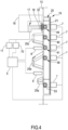
- the cycler 2 comprises an electronic control unit 5 ( Figs. 4 ), a roller peristaltic pump 6 ( Fig.1 ), a plurality of occlusion elements 7, a first or high level sensor 8 and a second or low level sensor 9, a pressure transducer 10 and an air pump 11 (schematically illustrated in Fig. 4 ).
- the cycler 2 may also comprise a heater, not shown.
- the peristaltic pump shown in Figures 3 and 25 comprises two pressing rollers 6a angularly spaced of 180°.
- a motor, not shown, of the peristaltic pump 6 is housed in the box 4 and a rotor 12 of the peristaltic pump 6 is positioned on a front panel 13 of the box 4 ( Fig.1 ).
- a site 14 of the front panel 13 next to the rotor 6 is configured to retain in removable manner the manifold assembly 3 on said front panel 13.
- the site 14 may comprise retaining elements configured to be coupled to the manifold assembly 3 and/or the manifold assembly 3 comprises hooking elements configured to hook, in removable manner, said disposable assembly 3 to the front panel 13 of the cycler 2.
- the occlusion elements 7 protrude from the front panel at the site 14.
- Each occlusion element 7 comprises a plunger 15 ( Figs.6A and 6B ) moved by a respective actuator, not shown, housed in the box 4.
- the actuator is configured to move the plunger 15 between a retracted position ( Fig.6A ) and a forward position ( Fig.6B ), as will be discussed herein.
- the first level sensor 8 and the second level sensor 9 are installed on the lid 16 and protrude from a side of the lid 16 configured to face the front panel 13 and/or the manifold assembly 3 when the lid 16 is in the closed position ( Fig.4 ).
- the illustrated level sensors 8, 9 are capacitive sensors. In other embodiments, not shown in the attached Figures, the level sensors 8, 9 may be ultrasonic sensors or other type of sensors and/or may be installed on the front panel of the box 4.
- An air conduit 17 is mounted on the lid 16 and comprises a coupling end 18.
- the coupling end 18 is configured to face the manifold assembly 3 when the lid 16 is in the closed position ( Figs.4 and 5 ), as will be discussed herein.
- the air conduit 17 is in air communication with the pressure transducer 10 and the air pump 11.
- the pressure transducer 10 and the air pump 11 may be installed in the lid 16 or in the box 4.
- the control unit 5 is operationally connected to the motor of the peristaltic pump 6, to the actuators of the occlusion elements 7, to the pressure transducer 10 and the air pump 11, to the first level sensor 8 and second level sensor 9, to the heater and to any other device or sensor of the cycler 2 and is configured/programmed to control operation of the peritoneal dialysis apparatus 1.
- the control unit may be also connected to a display, a keyboard or a touch screen 100 configured to show working parameters of the apparatus 1 and/or to allow a user to set up the apparatus 1 ( Fig.1 ).
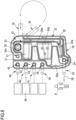
- the manifold assembly 3 for the peritoneal dialysis apparatus 1 comprises a disposable casing 19 comprising a rigid molded plastic rigid shell 20, e.g. made of PETG (polyethylene terephthalate glycol-modified) polymer ( Figs. 2 , 3 and 4 ), and a plastic sheet 21, e.g. a polyvinyl chloride soft sheet ( Fig. 4 ).
- the rigid molded plastic rigid shell 20 delimits a front and sides of the casing 19 and the plastic sheet 21 is a back of the casing 19 ( Fig.4 ).
- the plastic rigid shell 20 has a substantially flattened shape and comprises septa and recesses on the inner side of the casing 19.
- Said septa delimit internally a first compartment 22 and a second compartment 23 for fresh and spent dialysis fluid ( Fig.3 ).
- Said recesses delimit internally respective three expansion chambers 24a, 24b, 24c and externally, on the front of the casing 19, respective three protrusions 25a, 25b, 25c ( Figs 2 and 3 ).
- the plastic rigid shell 20 and the casing 19 have a substantially rectangular outline with two long sides and two short sides. When the casing 19 is properly mounted on the cycler 2, the two long sides are vertical.
- the first compartment 22 is delimited by an outer septum 26 positioned on a peripheral border of the plastic rigid shell 20 and by a first inner septum 27.
- the first inner septum 27 has a first extremity connected to the outer septum 26 on the top short side of the plastic rigid shell 20 and a second extremity connected to the outer septum 26 on the right long side of the of the plastic rigid shell 20.
- the first inner septum 27 has a substantially U-shape and develops substantially parallel to the left long side, to the bottom short side and to the right long side of the plastic rigid shell 20.
- the first compartment 22 is a U-shaped first elongated passage.
- the second compartment 23 is delimited by the first inner septum 27 and by a portion of the outer septum 26 not delimiting the first compartment 22, such that the second compartment 23 is partly surrounded by the U-shaped first compartment 22.
- a second inner septum 28 is positioned inside the second compartment 23 to create a route in the second compartment 23.
- the second inner septum 28 has a first extremity connected to the first inner septum 27 at a location close to the first extremity of said first inner septum 27 and a second free extremity positioned close to a lower right corner of the plastic rigid shell 20.
- the second inner septum 28 has a substantially inverted U-shape and develops substantially parallel to the top short side and to the right long side of the plastic rigid shell 20. Therefore, the second compartment 23 comprises an inverted U-shaped second elongated passage.
- a long stretch of the inverted U-shaped second elongated passage is parallel to a right long stretch of the U-shaped first elongated passage.
- the second compartment 23 comprises a main central part divided, in part, from the second elongated passage by the second inner septum 28.
- the second elongated passage has a second extremity communicating with the main central part.
- the three expansion chambers 24a, 24b, 24c are fashioned in the main central part of the second compartment 23 and each expansion chamber 24a, 24b, 24c has a depth greater than a depth of a remaining part of the second compartment 23.
- Two through apertures 29a, 29b pass through the plastic rigid shell 20 and the main central portion of the second compartment 23. These two through apertures are surrounded and delimited by respective further septa 30 connected to the first inner septum 27 Therefore, also these further septa 30 delimit the second compartment 23.
- a first aperture 29a and a second aperture 29b are positioned between two of said three of expansion chambers 24a, 24b, 24c.
- a first expansion chamber 24a of the three expansion chambers 24a, 24b, 24c is close to the bottom short side of the casing 19 and to a short stretch of the U-shaped first elongated passage;
- a second expansion chamber 24b of the three expansion chambers 24a, 24b, 24c is placed between the first aperture 29a and the second aperture 29b;
- a third expansion chamber 24c of the three expansion chambers 24a, 24b, 24c is placed above the second aperture 29b.
- An inner volume delimited in the second compartment 23 is greater than an inner volume delimited in the first compartment 22.
- the inner volume of the second compartment 23 is about 55 m 3 and the inner volume of the first compartment 22 is about 14 m 3 .
- a hole 31 ( Fig.3 ) is fashioned in the front of the plastic rigid shell 20 located between the third expansion chamber 24c and the second inner septum 28.
- a rigid plastic frame 32 supporting a breathable membrane 33 ( Fig.2 ) is joined, by welding or gluing, to an edge of the hole 31.
- the breathable membrane 33 may be of PTFE (polytetrafluoroethylene).
- an upper part of the second compartment 23 provided with the breathable membrane 33 delimits an air buffer volume, as will be discussed herein.
- the plastic sheet 21 ( Fig.4 ) is welded or glued to the plastic rigid shell 20
- the plastic sheet 21 is joined to the outer septum 26, the first inner septum 27, the second inner septum 28 and to the further septa 30, to seal the first compartment 22 and the second compartment 23.
- the plastic rigid shell 20 comprises a first pump port 34 comprising a hollow cylinder protruding from a right side (in Figs. 3 and 8 - 11 ) of the casing 19.
- the first pump port 34 is in fluid communication with the first compartment 22.
- the first pump port 34 opens inside the first compartment 22 at an extremity of the right long stretch of the U-shaped first elongated passage.
- the plastic rigid shell 20 comprises a second pump port 35 comprising a hollow cylinder protruding from the right side (in Figs. 3 and 7 - 10 ) of the casing 19.
- the second pump port 35 is in fluid communication with the second compartment 23.
- the second pump port 35 opens inside the second compartment 23 at a first extremity of the second elongated passage.
- the first pump port 34 and the second pump port 35 are close to each other but separated by the first inner septum 27.
- the hollow cylinders defining the first pump port 34 and the second pump port 35 diverge from each other away from the casing 19.
- the plastic rigid shell 20 comprises a drain port 36 comprising a hollow cylinder 37 protruding from the left side (in Figs. 3 and 7 - 10 ) of the casing 19.
- the hollow cylinder 37 of the drain port 36 passes through the outer septum 26 such that said drain port 36 is in fluid communication with the first compartment 22.
- the drain port 36 comprises a short hollow barrel 38 connected to the hollow cylinder 37.
- a central axis of the hollow cylinder 37 is perpendicular to a main axis of the hollow barrel 38 and the cavities delimited inside the hollow cylinder 37 and the hollow barrel 38 are in fluid communication with each other.
- the hollow barrel 38 protrudes from a bottom surface of the first compartment 22 and opens inside the first compartment 22 ( Figs.6A and 6B ).
- the hollow barrel 38 is shorter than the adjacent outer septum 26 (as shown in Figs. 6A and 6B ), than the first inner septum 27, than the second inner septum 28, than the further septa 30, such that the plastic sheet 21 is spaced from an edge of the hollow barrel 38, when said plastic sheet 21 is not deformed, as shown in Fig.6A .
- the edge of the hollow barrel 38 and a part of the plastic sheet 21 facing said edge form a drain valve 39 of the drain port 36.
- the plastic rigid shell 20 further comprises a first dialysis port 40 and a second dialysis port 41.
- Each of these ports 40, 41 protrudes from the left side (in Figs. 3 and 7 - 10 ) of the casing 19 and has the same structure as the drain port 36 detailed above (hollow cylinder 37 and hollow barrel 38).
- the first dialysis port 40 and a second dialysis port 41 have a receptive first dialysis valve 42 and a respective second dialysis valve 43.
- the plastic rigid shell 20 further comprises a heater port 44 which also protrudes from the left side (in Figs. 3 and 7 - 10 ) of the casing 19 and is structurally similar to the drain port 36 detailed above (hollow cylinder 37 and hollow barrel 38).
- the heater port 44 has a heater valve 45. The heater port 44 is placed close to an upper left corner of the plastic rigid shell 20.
- the hollow barrel 38 of the heater port 44 is also in fluid communication with an opening 46 fashioned through the front of the casing 19 ( Fig.7 ).
- the plastic rigid shell 20 comprises a further hollow barrel 47 placed in the second compartment 23 and close to the hollow barrel 38 of the heater port 44.
- the first inner septum 27 is located between the further hollow barrel 47 and the hollow barrel 38.
- the further hollow barrel 47 is in fluid communication with a further opening 48 fashioned through the front of the casing 19 ( Fig.7 ) and the opening 46 and the further opening 48 are connected by a by-pass channel 49 delimited by a cover 50 welded or glued to the front of the plastic rigid shell 20.
- the by-pass channel 49 is in fluid communication with the first compartment 22, with the second compartment 23 and with the heater line tube 63.
- An edge of the further hollow barrel 47 and a part of the plastic sheet 21 facing said edge form a by-pass valve 51.
- the further hollow barrel 47 is part of a by-pass port 52 provided with the by-pass valve 51.
- the second inner septum 28 separates an area of the second compartment 23 with the hole 31 and the breathable membrane 33 from the by-pass valve 51 ( Figs 3 and 8 ).
- the plastic rigid shell 20 further comprises a patient port 53.
- the patient port 53 protrudes from the left side (in Figs. 3 and 7 - 10 ) of the casing 19 and has the same structure as the drain port 36 detailed above (hollow cylinder 37 and hollow barrel 38).
- the hollow cylinder 37 of the patient port 53 passes through the outer septum 26 and the first inner septum 27 such that said patient port 53 is in fluid communication with the second compartment 23 ( Fig.3 ).
- the patient port 53 has a patient valve 54.
- All the valves are structurally and functionally identical and, when the manifold assembly 3 is properly mounted on the cycler 2, they are each placed in front of a respective occlusion element 7 of the cycler 2.
- Each occlusion element 7 of the cycler 2 is configured to open or close the respective valve ( Figs 6A and 6B ).
- the occlusion element 7 may be installed on the lid 16 and the structure of the manifold assembly 3 is such to cooperate with said occlusion element 7 on the lid 16.
- the hollow cylinders 37 of the heater port 44, the first dialysis port 40, the second dialysis port 41, the drain port 36 and the patient port 53 are parallel with respect to each other.
- the heater port 44 is above the first dialysis port 40 which in turn is above the second dialysis port 41 which in turn is above the drain port 36 which in turn is above the patient port 53.
- the first compartment 22 shaped like a U-shaped first elongated passage extends between the heater port 44 and the first end of the first pump port 34.
- the second elongated passage has a first extremity connected to the second pump port 35.
- the manifold assembly 3 comprises a yielding pump tube 55 having a first end 56 connected to the first pump port 34 and to first compartment 22 and a second end 57 connected to the second pump port 35 and to the second compartment 23 ( Fig. 1 ).
- the yielding pump tube 55 extends outside the casing 19 and is shaped as a loop or as an eyelet having an omega " ⁇ " shape to be placed in part around the rotor 12 of the peristaltic pump 6 of the cycler 2.
- the manifold assembly 3 further comprises ( Fig.3 ): a patient line tube 58 having a first end connected to the patient port 53 and a second end connectable to a patient's peritoneal cavity; a first dialysis fluid line tube 59 having a first end connected to the first dialysis port 40 and a second end connected to a first supply bag 60; a second dialysis fluid line tube 61 having a first end connected to the second dialysis port 41 and a second end connected to a second supply bag 62; a heater line tube 63 having a first end connected to the heater port 44 and a second end connected to a heater bag 64; a drain fluid line tube 65 having a first end connected to the drain port 36 and a second end connected to a drain 66.
- the patient line tube 58 may extend to a patient line connector, which may for example connect to a patient's transfer set leading to an indwelling catheter that extends to the patient's peritoneal cavity.
- the first compartment 22, the yielding pump tube 55 and the second compartment 23 delimit together a fluid path extending between one of the first dialysis fluid line tube 59, second dialysis fluid line tube 61, heater line tube 63, drain fluid line tube 65 and the patient line tube 58, to allow fluid flow from one of the fluid line tubes to the patient line tube 58 or from the patient line tube 58 to one of the fluid line tubes when the peristaltic pump 6 of the cycler 2 is actuated.
- the casing 19 of the manifold assembly 3 is mounted on the front panel 13 of the cycler 2, the yielding pump tube 55 is coupled to the rotor 12 and the first dialysis fluid line tube 59, second dialysis fluid line tube 61, heater line tube 63, drain fluid line tube 65 are properly arranged and connected to the respective first supply bag 60, second supply bag 62, heater bag 64 and drain 66.
- the patient line tube 58 is properly arranged and connected to the patient P.
- the heater bag 64 is coupled to the heater of the cycler 2.
- the shape of the casing 19, with the three protrusions 25a, 25b, 25c and the two through apertures 29a, 29b, facilitate the user to grab the casing 19 and to mount the casing 19 on the cycler 2.
- the user closes the lid 16 so that the first level sensor 8 and the second level sensor 9 are positioned in front of an external flat surface of the casing 19.
- the position of the first level sensor 8 and the second level sensor 9 when the lid 16 is closed is shown in Fig.2 and Fig.4 .
- Fig.2 the positions of the first level sensor 8 and second level sensor 9 are schematically represented through dashed line circles.
- the first level sensor 8 and the second level sensor 9 are placed one above the other.
- the first level sensor 8 is positioned between the third expansion chamber 24c and the second expansion chamber 24b.
- the second level sensor 9 is positioned between the second expansion chamber 24b and the first expansion chamber 24a.
- the coupling end 18 of the air conduit 17 is coupled to the rigid plastic frame 32 supporting the breathable membrane 33 ( Figs.4 and 5 ) such that the coupling end 18 faces the breathable membrane 33.
- the pressure transducer 10 and the air pump 11 of the cycler 2 are put into communication with the breathable membrane 33 and with the upper part of the second compartment 23, i.e. with the air buffer volume.
- control unit 5 commands the actuators of the occlusion elements 7 to open or close the drain valve 39, first dialysis valve 42, second dialysis valve 43, heater valve 45, by-pass valve 51 and patient valve 54 according to the steps to be performed.
- the patient line tube 58 When the valve 54 of the patient port 53 is open, the patient line tube 58 is in fluid communication with the second compartment 23, when the valve 54 of the patient port 53 is closed, fluid communication between the patient line tube 58 and the second compartment 23 is prevented.
- the first dialysis fluid line tube 59 When the first dialysis valve 42 of the first dialysis fluid port 40 is open, the first dialysis fluid line tube 59 is in fluid communication with the first compartment 22, when the first dialysis valve 42 of the first dialysis fluid port 40 is closed, fluid communication between the first dialysis fluid line tube 59 and the first compartment 22 is prevented.
- the heater line tube 63 When the heater valve 45 of the heater port 44 is open, the heater line tube 63 is in fluid communication with the first compartment 22, when the heater valve 45 of the heater port 44 is closed, fluid communication between the heater line tube 63 and the first compartment 22 is prevented.
- the drain fluid line tube 65 When the drain valve 39 of the drain port 36 is open, the drain fluid line tube 65 is in fluid communication with the first compartment 22, when the drain valve 39 of the drain port 36 is closed, fluid communication between the fluid drain line tube 65 and the first compartment 22 is prevented.
- the plunger 15 of the occlusion element 7 When the actuator moves the plunger 15 of the occlusion element 7 in the forward position of Fig.6B and keeps the plunger 15 in said forward position, the plunger 15 is accommodated in part in the hollow barrel 38.
- the plunger 15 pushes, deforms and keeps a portion of plastic sheet 21 against the edge of the hollow barrel 38.
- the hollow barrel 38 is a seat for the plunger 15 and for the portion of plastic sheet 21 trapped between. A fluid flow between the hollow barrel 38 and the first compartment 22 is prevented (valve closed). All valves work in this way.
- Table 1 Step From To Valves Open Pump Direction 1 Heater bag Drain By-pass valve ClockWise Drain valve 2 First supply bag Expansion chambers First dialysis valve CounterClockWise 3 Expansion chambers Drain Drain valve ClockWise 4 Second supply bag Expansion chambers Second dialysis valve CounterClockWise 5 Expansion chambers Drain Drain valve ClockWise 6 Heater bag Patient Heater valve CounterClockWise Patient valve
- Another priming procedure may be performed using communication vessels as disclosed in the following Table 2.
- Table 2 Step From To Valves Open Pump Direction 1 Heater bag Patient line tube All valves and yielding pump tube open -
- patient treatment may be started.
- the control unit 5 commands the peritoneal dialysis apparatus 1 to move the dialysis fluid from the first supply bag 60 to the patient P.
- the control unit 5 closes and keeps closed the heater valve 45, the by-pass valve 51, the second dialysis valve 43 and the drain valve 39, opens and keeps open the first dialysis valve 42 and the patient valve 54.
- the control unit 5 commands the motor to rotate the peristaltic pump 6 in a first rotation direction (CounterClockWise in Fig.8 ) to pump the dialysis fluid from the first compartment 22 to the second compartment 23.
- An auxiliary in-line heater may be placed on the first dialysis fluid line tube 59 to heat the dialysis fluid while flowing through said dialysis fluid line tube 59 and towards the patient P.
- the control unit 5 commands the peritoneal dialysis apparatus 1 to move the dialysis fluid from the first supply bag 60 towards the heater bag 64.
- the auxiliary in-line heater is not used.
- the control unit 5 opens and keeps open the by-pass valve 51 and the first dialysis valve 42 while closes and keeps closed the heater valve 45, the second dialysis valve 43, the drain valve 39 and the patient valve 54.
- the control unit 5 commands the motor to rotate the peristaltic pump 6 in a first rotation direction (CounterClockWise in Fig.9 ) to pump the dialysis fluid from the first compartment 22 to the second compartment 23 and then to the heater bag 64 through the by-pass channel 49.
- control unit 5 commands the peritoneal dialysis apparatus 1 to move the heated dialysis fluid from the heater bag 64 towards the patient P.
- the control unit 5 opens and keeps open the heater valve 45 and the patient valve 54 and closes and keeps closed the by-pass valve 51, the first dialysis valve 42, the second dialysis valve 43 and the drain valve 39.
- the control unit 5 commands the motor to rotate the peristaltic pump 6 in a first rotation direction (CounterClockWise in Fig.10 ) to pump the dialysis fluid from the first compartment 22 to the second compartment 23.
- the spent dialysis fluid is removed from the patient P.
- the control unit 5 commands the peritoneal dialysis apparatus 1 to move the spent dialysis fluid from the patient P towards the drain 66.
- the control unit 5 opens and keeps the drain valve 39 and the patient valve 54 and closes and keeps closed the heater valve 45, the by-pass valve 51, the first dialysis valve 42, the second dialysis valve 43.
- the control unit 5 commands the motor to rotate the peristaltic pump 6 in a second rotation direction (ClockWise in Fig.11 ) to pump the dialysis fluid from the second compartment 23 to the first compartment 22.
- Table 3 Step From To Valves Open Pump Direction 1 First supply bag Heater bag First dialysis valve CounterClockWise By-pass valve 2 Heater bag Patient Heater valve CounterClockWise Patient valve 3 Patient Drain Drain valve Patient valve ClockWise
- Figures 16 and 17 show another embodiment of the manifold assembly 3 of the peritoneal dialysis apparatus 1 (APD).
- the cycler 2 of this embodiment is not shown and may have the same structure/architecture disclosed for the first embodiment.
- the manifold assembly 3 ( Figs. 16 and 17 ) that organizes tubing and performs many functions discussed herein is different from the manifold assembly 3 of embodiment 1 in the following features.
- first dialysis port 40 and the second dialysis port 41 open inside the second compartment 23 instead of the first compartment 22.
- the first dialysis valve 42 and the second dialysis valve 43 are positioned in the second compartment 23 and close to the second expansion chamber 24b.
- the first dialysis fluid line tube 59 has the first end connected to the first supply bag 60 and the second end connected to the second compartment 23.
- the second dialysis fluid line tube 61 has the first end connected to the second supply bag 62 and the second end connected to the second compartment 23.
- drain port 36 and the drain fluid line tube 65 are arranged close to a top of the casing 19 and, when the manifold assembly 3 is properly mounted on the cycler 2, are located above the heater port 44 and the heater line tube 63.
- the second inner septum 28 has a first extremity connected to the right long side of the plastic rigid shell 20, close to the second pump port 35 and, differently from the embodiment of Figure 3 , the area of the second compartment 23 with the hole 31 and the breathable membrane 33 is not separated from the by-pass valve 51 by said second inner septum 28.
- hole 31 and the breathable membrane 33 are next to the top short side of the plastic rigid shell 20.
- An area 67 of the plastic sheet 21 is configured to be coupled to displacement sensor 68 (shown only schematically) of the cycler 2 when the manifold assembly 3 is properly mounted on the cycler 2.
- Figure 16 shows that said area 67 faces a zone of the first compartment 22 located at a right bottom elbow the substantially U-shaped first elongated passage.
- the displacement sensor 68 is mounted on the front panel 13 of the cycler 2.
- the flow route from the first supply bag 60 to the heater bag 64 is other than the one shown in Fig.9 .
- the control unit 5 opens and keeps open the heater valve 45 and the first dialysis valve 42 while closes and keeps closed the by-pass valve 51, the second dialysis valve 43, the drain valve 39 and the patient valve 54.
- the control unit 5 commands the motor to rotate the peristaltic pump 6 in the second rotation direction (ClockWise in Fig.9 ) to pump the dialysis fluid from the second compartment 23 to the first compartment 22.
- Table 4 The treatment sequence for the manifold assembly 3 of the second embodiment is shown in the following table (Table 4).
- Table 4 Step From To Valves Open Pump Direction 1 First supply bag Heater bag Heater valve ClockWise First dialysis valve 2 Heater bag Patient Heater valve CounterClockWise Patient valve 3 Patient Drain Drain valve ClockWise Patient valve
- Table 5 Step From To Valves Open Pump Direction 1 Heater bag Drain By-pass valve ClockWise Drain valve 2 First supply bag Drain First dialysis valve ClockWise Drain valve 3 Second supply bag Drain Second dialysis valve ClockWise Drain valve 4 Heater bag Patient Heater valve CounterClockWise Patient valve
- Figures 19 shows another embodiment of the manifold assembly 3 of the peritoneal dialysis apparatus 1 (APD).
- the cycler 2 of this embodiment is different from the first embodiment, because the valves are not part of the casing 7 and the occlusion elements of the cycler 2 are pinch valves.
- All the ports do not comprise valves or part of valves.
- the drain port 36 and the drain fluid line tube 65 are arranged close to a top of the casing 19, like in the second embodiment.
- the second inner septum 28 separates the area of the second compartment 23 with the hole 31 and the breathable membrane from an area of the second compartment 23 with an auxiliary drain port 69 connected to an auxiliary drain fluid line tube 70.
- the drain valve 39, first dialysis valve 42, second dialysis valve 43, heater valve 45, patient valve 54 are clamps part of the cycler 2 and operating on tube sections of the drain fluid line tube 65, first dialysis fluid line tube 59, second dialysis fluid line tube 61, heater line tube 63, patient line tube 58.
- the clamp and the tube section form together a pinch valve.
- an auxiliary drain valve 71 works on the auxiliary drain fluid line tube 70 and the drain fluid line tube 65 merges with the auxiliary drain fluid line tube 70 in a common drain line before reaching the drain 66 ( Figure 19 ).
- the flow route from the first supply bag 60 to the heater bag 64 is the same of the second embodiment (see Table 3).
- Table 6 A possible priming sequence is represented in the following table (Table 6).
- Table 6 Step From To Valves Open Pump Direction 1 Heater bag Drain Heater valve CounterClockWise Auxiliary drain valve 2 First supply bag Drain First dialysis valve ClockWise Drain valve 3 Second supply bag Drain Second dialysis valve ClockWise Drain valve 4 Heater bag Patient Heater valve CounterClockWise Patient valve
- valves are part of the casing and are shaped like in Figures 20A, 20B, 20C .
- all the valves (drain valve 39, first dialysis valve 42, second dialysis valve 43, heater valve 45, by-pass valve 51, patient valve 54) of embodiment two of Figures 16 and 17 are of the type shown in Figure 20A .
- This kind of valves is configured to work with the occlusion element 7 illustrated in Figures 21A, 21B, 21C, 21D , 22 and 23 .
- the occlusion element 7 comprises the plunger 15, like the one of Figures 6A, 6B and 7 , and further comprises a mechanical tensioning plunger 76. Both the plunger 15 and the tensioning plunger 76 are mechanically coupled to an actuator 73, shown in Figures 22 and 23 .
- the actuator 73 is a linear actuator connected to a shaft 74.
- a distal end of the shaft 74 carries the plunger 15 and a damping and/or resilient element 75 (like a spring) is placed between the distal end and said plunger 15.
- the plunger 15 is shaped like a cup housing the spring.
- the damping and/or resilient element 75 allows to reduce the force exerted on the membrane 21 to avoid damaging said membrane 21.
- the actuator 73 is configured to move the plunger 15 along an axial direction and between the retracted position, in which the plunger 15 is spaced from the soft membrane 21 and the port is open, and a forward position, in which the plunger 15 is at least in part accommodated in the seat and the soft membrane 21 is deformed and trapped between said plunger 15 and said seat to close the port.
- the membrane tensioner 72 is configured to raise the soft membrane 21 away from the seat when the plunger 15 goes back to the retracted position and to counteract a possible negative pressure tending to keep the valve closed.
- the membrane tensioner 72 comprises a tensioning plunger 76 which is also mechanically connected to the actuator 73.
- the tensioning plunger 76 is shaped substantially like a cylinder, is coaxial to the plunger 15 and surrounds at least in part the plunger 15.
- the tensioning plunger 76 comprises two arched walls 76a coaxial to a central axis.
- the walls 76a are spaced one from the other to delimit two windows 76b between them ( Figures 24 and 25 ).
- the tensioning plunger 76 is fitted on the shaft 74 and is axially movable along said shaft 74. Borders of the arched walls 76a of the tensioning plunger 76 face the soft membrane 21 and the plunger 15 may protrude from the tensioning plunger 76.
- the actuator 73 is also configured to move the tensioning plunger 76 between a retracted position, in which the tensioning plunger 76 is spaced from the soft membrane 21, and a forward position, in which the tensioning plunger 76 engages the soft membrane 21 at locations other than an edge of the seat, to move away the soft membrane 21 from the edge and to stretch said soft membrane 21 above the seat.
- the tensioning plunger 76 may be moved by an auxiliary actuator, not shown.
- the actuator 73 is housed in the box 4 of the cycler 2; the plunger 15, the tensioning plunger 76 and the shaft 74 are guided through openings fashioned in the box 4 of the cycler 2.
- the tensioning plunger 76 is in the retracted position when the plunger 15 is in the forward position ( Figures 21A and 21B ). In this configuration, the plunger 15 protrudes from the tensioning plunger 76.
- the tensioning plunger 76 is in the forward position when the plunger 15 is in the retracted position ( Figures 21C and 21D ). In this configuration, the plunger 15 is entirely housed within the tensioning plunger 76 and does not protrude beyond the borders of the tensioning plunger 76.
- the occlusion element 7 comprises a reverse mechanism connecting the tensioning plunger 76 and the plunger 15.
- the reverse mechanism is configured to move the plunger 15 in an opposite direction with respect to a moving direction of the tensioning plunger 76 when the plunger 15 is moved by the actuator 73.
- the tensioning plunger 76 comprises a projection 77 extending parallel to the shaft 74 and a rocker lever 78.
- a first end of the rocker lever 78 is hinged to the shaft 74 of the plunger 15
- a second end of the rocker lever 78 is hinged to the projection 77 of the tensioning plunger 76 and a middle portion of the rocker lever 78 is hinged to a stationary part of the cycler 2, for instance to a part of the box 4.
- the variant embodiment of Figure 22A comprises an additional damping and/or resilient element 75a (a spring) coupled to the tensioning plunger 76.
- the cylinder defining the tensioning plunger 76 is in two parts. A first part is rigidly connected to the projection 77. A second part carries the borders of the arched walls 76a of the tensioning plunger 76 facing the membrane 21.
- the additional damping and/or resilient element 75a is interposed between the first and the second part.
- the additional damping and/or resilient element 75a allows to reduce the force exerted on the membrane 21 by the tensioning plunger 76, to avoid damaging said membrane 21.
- a further function of the additional damping and/or resilient element 75a is to compensate for possible plastic deformation of the membrane 21 that may lose elasticity and may plastically deform over time. Even if the membrane 21 is plastically stretched, the additional damping and/or resilient element 75a is always able to push the borders of the arched walls 76a of the tensioning plunger 76 against the membrane 21 (forward position), to move away said soft membrane 21 from the edge and to stretch said soft membrane 21 above the seat.
- the actuator 73 is a stepper motor comprising a rotatable shaft 79 connected to the shaft 74 of the plunger 15.
- the rotatable shaft 79 has an outer thread and is coupled, through a left hand threaded coupling 80, to an inner thread of the shaft 74.
- the shaft 74 has an outer thread and is coupled, through a right hand threaded coupling 81, to an inner thread of the tensioning plunger 76.
- the tensioning plunger 76 and the shaft 74 are axially guided by a stationary element 82, for instance to a part of the box 4.
- the rotation of the rotatable shaft 79 caused by the stepper motor makes the shaft 74 moving only axially in a first direction (the shaft 74 does not revolve), e.g. towards the forward position of the plunger 15.
- the axial movement of the shaft 74 drives the rotation of the tensioning plunger 76 and, due to a different pitch of the left hand threaded coupling 80 and right hand threaded coupling 81, also the axial movement of said tensioning plunger 76 in a second direction, opposite the first direction, e.g. towards a retracted position of the tensioning plunger 76.
- the stepper motor moves the plunger 15 towards the forward position
- the left hand threaded coupling 80 and right hand threaded coupling 81 work to move the tensioning plunger 76 towards the retracted position.
- the left hand threaded coupling 80 and right hand threaded coupling 81 work to move the tensioning plunger 76 towards the forward position.
- the valve In order to properly work with the plunger 15 and with the membrane tensioner 72, the valve has a circular edge 83 delimiting the seat and also an auxiliary edge 84 extending in part around the circular edge 83 and spaced with respect to said edge 83.
- the valve comprises a shaped member 85 which protrudes from the bottom surface of the respective compartment 22, 23 and comprises the edge 83 and the auxiliary edge 84.
- the shaped member 85 is substantially cylindrical and delimits a central cylindrical cavity 86.
- the edge 83 delimits an upper part of said cavity 86 and the auxiliary edge 84 comprises two arch shaped parts coaxial to the cavity and to the edge 83.
- the auxiliary edge 84 is raised with respect to the edge 83 such that, when the manifold assembly 3 is properly mounted on the site 14 of the cycler 2, the auxiliary edge 84 is closer to the occlusion element than the edge 83.
- Figures 21A to 21D show working steps of the assembly comprising the valve and the occlusion element 7.
- the shaped member 85 is at least in part positioned inside the tensioning plunger 76.
- Each arched wall 76a of the tensioning plunger 76 is placed close to one of the two arch shaped part of the auxiliary edge 84 and radially outside said arch shaped part of the auxiliary edge 84, as shown in Figure 25 .
- the windows 76b face radial openings delimited between the arched walls 76a and allow fluid communication between the cylindrical cavity 86 and the first or second compartment 22, 23, therefore the valve is open ( Figure 21D ).
- valve and occlusion element 7 just disclosed may be also part of other kind of medical apparatuses (e.g. dialysis apparatuses for extracorporeal treatment of blood), not necessarily of the peritoneal dialysis apparatus disclosed above.
- the medical apparatus may comprise a dialysis machine and a manifold assembly and the manifold assembly is mounted or mountable on the dialysis machine.
- the manifold assembly comprises a casing comprising a rigid shell and at least one soft membrane, the rigid shell and soft membrane delimit at least a first fluid passage.
- the rigid shell comprises at least one port in fluid communication with the first fluid passage and with a second fluid passage.
- the at least one port has a seat and the soft membrane facing the seat.
- the dialysis machine comprises at least one occlusion element 7 which, when the manifold assembly is properly mounted on the dialysis device, faces the seat with the soft membrane 21 there between.
- the seat is configured for accommodating, at least partially, a respective occlusion element 7 of the dialysis machine.
- the dialysis apparatus may be an apparatus for extracorporeal treatment of blood comprising: a blood treatment device; an extracorporeal blood circuit coupled to the blood treatment device; a blood pump, wherein a pump section of the extracorporeal blood circuit being configured to be coupled to the blood pump; a treatment fluid circuit operatively connected to the extracorporeal blood circuit and/or to the blood treatment device.
- the treatment fluid circuit comprises a dialysis line connected to a fluid chamber of the treatment unit and a fluid evacuation line connected to the fluid chamber.
- the treatment fluid circuit comprises an infusion circuit comprising one or more infusion lines of a replacement fluid.
- the manifold assembly may be part of the extracorporeal blood circuit or of the treatment fluid circuit.
- the manifold assembly 3 described above may be used to calibrate the peristaltic pump 6, i.e. to estimate the stroke liquid volume of the yielding pump tube 55 connected to the peristaltic pump 6 in order to reach volumetric accuracy measure requirements.
- the peristaltic pump 6 comprises an encoder or is coupled to an encoder, not shown in the attached Figures.
- the encoder is operatively connected to the control unit 5 and is configured to detect the position and movement of the pressing rollers 6a of the peristaltic pump 6.
- the control unit 5 is operatively connected the motor of the peristaltic pump 6, to the first level sensor 8, to the second level sensor 9, to the air valve 10, to the actuators of the occlusion elements 7 and to the pressure transducer 10 and is configured and/or programmed to calibrate the peristaltic pump 6 according to the method here detailed.
- the first level sensor 8 or high level sensor and the second level sensor 9 or low level sensor delimit a high level "C” and a low level "A" in the second compartment 23.
- a first volume “V1” is delimited in the second compartment 23 below the low level “A”.
- the first volume “V1” is about 10 ml.
- a second volume “V2” is delimited in the second compartment 23 between the low level “A” and the high level “C”.
- the second volume “V2” is between two and four times a nominal stroke liquid volume of the peristaltic pump 6.
- the nominal stroke liquid volume of the peristaltic pump 6 may be 7 ml and the second volume “V2" is about 21 ml.
- a third volume “V3” is delimited in the second compartment 23 above the high level “C”.
- the third volume “V3” is about 15 ml.
- the auxiliary chamber 87 delimits inside a fourth volume "V4" of a about 26 ml.
- a sum of the second, third and fourth volume is about 62 ml.
- the yielding pump tube 55 shaped as a loop comprises a rounded part 55a and two straight parts 55b.
- the rounded part 55a and two straight parts 55b form a single tube.
- the straight parts 55b are respectively connected to the first pump port 34 and the second pump port 35.
- the rounded part 55a is configured to be pressed and deformed/squeezed by the pressing rollers 6a of the peristaltic pump 6.
- each of the two pressing rollers 6a starts squeezing the rounded part 55a at a bottom portion, between the rounded part 55a and the lower of the two straight parts 55b, and releases the rounded part 55a at a top portion, between the rounded part 55a and the upper of the two straight parts 55b.
- the drain valve 39, first dialysis valve 42, second dialysis valve 43, by-pass valve 51, patient valve 54 are closed.
- the heater valve 45 is open and the heater bag 64 is filled with water.
- the air valve 89 is open.
- the control unit 5 controls the peristaltic pump 6 to start rotating counterclockwise, to pump water from the heater bag 64 into the first compartment 22 and then into the second compartment 23.
- the low level sensor 9 detects water (A II in Figure 27 )
- the peristaltic pump 6 is stopped.
- the peristaltic pump 6 is then rotated clockwise to lower the water level until water is no more detected by the low level sensor 9 and then stopped again (A I in Figure 27 ).
- the peristaltic pump 6 is again rotated counterclockwise.
- the control unit 5 controls the peristaltic pump 6 to keep rotating counterclockwise and pumping water in the second compartment 23. Meanwhile, the control unit 5 starts counting encoder pulses starting from the detection of water by the low level sensor 9.
- the position of one of the two pressing rollers 6a at the end of the predetermined angle "Delta” of rotation is a predetermined position.
- Such predetermined position may be at a portion of the yielding pump tube 55 between the rounded part 55a and one of the two straight parts 55b.
- the water level when the pressing roller 6a is in the predetermined position is the first level B.
- An extra volume “Extra_Volume” of water is pumped to raise the level from the low liquid level A to the first level B ( Figures 26 and 27 ).
- the rotational speed of the peristaltic pump 6 may be 5 rpm.
- Air pressure in the second compartment 23 is measured by the pressure transducer 10.
- An initial pressure P Init before air compression (first level B) and a final pressure P Final after air compression (second level D) are taken.
- the initial pressure P Init is about 0 mmHg (differential pressure with respect to atmospheric pressure) and the final pressure is about 400 mmHg.
- a variation of liquid volume "Vol_Moved” in the second compartment 23, due to the rotation of the peristaltic pump 6 of the predetermined rotation "Rotor_rev", is then calculated as a function of an initial air volume "Compensated _Volume” above the first level B and of the initial pressure P Init and the final pressure P Final .
- the initial air volume "Compensated _Volume” is a difference between a volume of air above the low liquid level “A” (i.e. V2 + V3 + V4) and the extra volume of water “Extra_Volume", wherein the extra volume of water “Extra_Volume” is the volume of water between the first level B and the low liquid level A, i.e. the volume of water moved by the rotation "Delta” of the peristaltic pump 6.
- the stroke liquid volume "Stroke_Vol_Press” of the peristaltic pump 6 is calculated as a ratio between the variation of liquid volume “Vol_Moved” and the "n" half-revolutions of the peristaltic pump 6.
- the calculation of the stroke liquid volume "Stroke_Vol_Press” as disclosed may be executed consecutively two to five times and an average stroke liquid volume is determined.
- the method of calibration may also be implemented in other medical apparatuses comprising a medical machine provided with a peristaltic pump and comprising a manifold assembly, for instance in an apparatus for extracorporeal treatment of blood of the kind above disclosed.
Landscapes
- Health & Medical Sciences (AREA)
- Heart & Thoracic Surgery (AREA)
- Emergency Medicine (AREA)
- Urology & Nephrology (AREA)
- Anesthesiology (AREA)
- Engineering & Computer Science (AREA)
- Vascular Medicine (AREA)
- Biomedical Technology (AREA)
- Hematology (AREA)
- Life Sciences & Earth Sciences (AREA)
- Animal Behavior & Ethology (AREA)
- General Health & Medical Sciences (AREA)
- Public Health (AREA)
- Veterinary Medicine (AREA)
- External Artificial Organs (AREA)
Description
- The present disclosure relates to a manifold assembly for a peritoneal dialysis apparatus and to a peritoneal dialysis apparatus comprising said manifold assembly. The present disclosure also relates to a method for controlling the peritoneal dialysis apparatus.
- Due to various causes, a person's renal system can fail. Renal failure produces several physiological derangements. It is no longer possible to balance water and minerals or to excrete daily metabolic load. Toxic end products of metabolism, such as, urea, creatinine, uric acid and others, may accumulate in a patient's blood and tissue.
- Reduced kidney function and, above all, kidney failure is treated with dialysis. Dialysis removes waste, toxins and excess water from the body that normal functioning kidneys would otherwise remove. Dialysis treatment for replacement of kidney functions is critical to many people because the treatment is lifesaving.
- One type of kidney failure therapy is peritoneal dialysis ("PD"), which infuses a dialysis solution, also called dialysis fluid, into a patient's peritoneal chamber via a catheter. The dialysis fluid is in contact with the peritoneal membrane in the patient's peritoneal chamber. Waste, toxins and excess water pass from the patient's bloodstream, through the capillaries in the peritoneal membrane, and into the dialysis fluid due to diffusion and osmosis, i.e., an osmotic gradient occurs across the membrane. An osmotic agent in the PD dialysis fluid provides the osmotic gradient. Used or spent dialysis fluid is drained from the patient, removing waste, toxins and excess water from the patient. This cycle is repeated, e.g., multiple times.
- There are various types of peritoneal dialysis therapies, including continuous ambulatory peritoneal dialysis ("CAPD"), automated peritoneal dialysis ("APD"), tidal flow dialysis and continuous flow peritoneal dialysis ("CFPD"). CAPD is a manual dialysis treatment. Here, the patient manually connects an implanted catheter to a drain to allow used or spent dialysis fluid to drain from the peritoneal chamber. The patient then switches fluid communication so that the patient catheter communicates with a bag of fresh dialysis fluid to infuse the fresh dialysis fluid through the catheter and into the patient. The patient disconnects the catheter from the fresh dialysis fluid bag and allows the dialysis fluid to dwell within the peritoneal chamber, wherein the transfer of waste, toxins and excess water takes place. After a dwell period, the patient repeats the manual dialysis procedure, for example, four times per day. Manual peritoneal dialysis requires a significant amount of time and effort from the patient, leaving ample room for improvement.
- Automated peritoneal dialysis ("APD") is similar to CAPD in that the dialysis treatment includes drain, fill and dwell cycles. APD machines, however, perform the cycles automatically, typically while the patient sleeps. APD machines free patients from having to manually perform the treatment cycles and from having to transport supplies during the day. APD machines connect fluidly to an implanted catheter, to a source or bag of fresh dialysis fluid and to a fluid drain. APD machines pump fresh dialysis fluid from a dialysis fluid source, through the catheter and into the patient's peritoneal chamber. APD machines also allow for the dialysis fluid to dwell within the chamber and for the transfer of waste, toxins and excess water to take place. The source may include multiple liters of dialysis fluid including several solution bags.
- APD machines pump used or spent dialysate from the patient's peritoneal cavity, though the catheter, and to the drain. As with the manual process, several drain, fill and dwell cycles occur during dialysis. A "last fill" may occur at the end of the APD treatment. The last fill fluid may remain in the peritoneal chamber of the patient until the start of the next treatment, or may be manually emptied at some point during the day.
- Known APD systems include a machine or cycler that accepts and actuates a disposable pumping device or cassette having a hard part and a soft part that is deformable for performing pumping and valving operations.
- Most of the cycler machines on the market implements pumping systems based on the compression/expansion of the fluids volume within expansion chambers that are part of a disposable device (alternating pumping system). The compression/expansion is performed by the action on the flexible diaphragm incorporated in the chambers of the disposable device, obtaining a continuous flow of boluses of fluid with volumes linked to the volumes of the expansion chambers itself. With such design, the flow rates and thus the fluids volumes exchange are controlled leveraging on the "Ideal Gas Law" combined with the knowledge of the chambers volumes and the pressure monitoring.
- Systems of this kind for performing peritoneal dialysis are disclosed, for instance, in
US 2011/0092893 andUS 2020/0230310 . - A main identified disadvantage of such approach refers to the management and modulation of low fluids flow rates, namely flow rate values of an order of magnitude smaller than the volumes of the expansion chambers of the device (typically >15 ml). In such range, the alternating pumping system leads to a discretization of the flow with a decreased level of accuracy. The possibility to manage carefully low flow rates is particularly important in the phase of drainage of fluid from the patient, which often is reported as a painful stage of the treatment for the patient.
- Furthermore, the alternating pumping approach results in a slight pulsatile flow that does not represent the best case for the mentioned phase of fluid drainage from the patient and for the administration phase too, in comparison with a smooth and laminar flow regime.
- Furthermore, sealing the fluid disposable device with a pneumatic path via a gasket to provide actuation has proven to be a potential field issue, which can delay treatment start time and affect user experience.
- Pneumatic cassette systems also produce acoustic noise, which may be a source of customer dissatisfaction.
- Some types of cycler machines leverage on the usage of scale for the control of the exchange fluids volumes. Drawback of this approach relate to the need of an accurate and frequent calibration of the scale present on the cycler machine, a procedure exposed to possible errors and which complicates the operations for managing the cycler maintenance.
- An additional drawback common to the existing solutions is the lack of a way to manage and remove the potential presence of gas bubbles within the "PD" solutions to be administered to the patient.
- Systems of performing peritoneal dialysis through a peristaltic pump are also known. For instance, such systems are disclosed in documents
WO2012129501A2 ,WO2019169081 ,US2005/0209563 , andWO 2018237375 . - These systems too have drawbacks related to need for calibration, pulsatile flow, removal of gas bubbles, etc..
- It is therefore an object of the present disclosure to provide a manifold assembly for a peritoneal dialysis apparatus and a peritoneal dialysis apparatus allowing a more accurate and simple control of the fluids flows and an enhanced monitoring of the effectiveness of the peritoneal dialysis treatment.
- It is an object of the present disclosure to provide a manifold assembly for a peritoneal dialysis apparatus and a peritoneal dialysis apparatus capable to guarantee a continuous flow with the possibility to modulate and assure high accuracy, also at a low flow rate range (e.g. 5-10 ml/min).
- It is a further object of the present disclosure to provide a manifold assembly and an apparatus able to manage the fluid levels and to assure to keep the fluid level within a defined range.
- It is a further object of the present disclosure to provide a manifold assembly and an apparatus that attenuates the effect of the peristalsis of the pump, providing a flow that does not present the pulsation typical of alternating pumping systems or of the prior art systems employing peristaltic pumps.
- It is a further object of the present disclosure to provide a manifold assembly and an apparatus providing a possible reduction of treatment times.
- It is a further object of the present disclosure to provide a manifold assembly and an apparatus allowing the detection of the potential occurrence of extreme negative pressure values in the chamber compartment connected to the drain and bags lines.
- It is a further object of the present disclosure to provide a manifold assembly and an apparatus capable of removing gas bubbles potentially present in the "PD" solutions before administration to the patient.
- It is a further object of the present disclosure to provide a manifold assembly and an apparatus offering the possibility to monitor the pressure values within a chamber compartment of said manifold assembly connected to the patient line and to adjust the fluid level of the chamber compartment.
- It is a further object of the present disclosure to provide a manifold assembly which is reliable and can be easily interfaced/coupled to the hardware components of a cycler of the apparatus.
- It is a further object of the present disclosure to provide a manifold assembly which can be easily handled and easily mounted/removed on/from the cycler of the apparatus by a user.
- At least one of the above objects is substantially reached by a manifold assembly for a peritoneal dialysis apparatus and a peritoneal dialysis apparatus according to the present disclosure. A manifold assembly for a peritoneal dialysis apparatus according to the present invention comprises the technical features as defined in independent claim 1.
-
-
Fig. 1 is a perspective view of one embodiment for an automated peritoneal dialysis apparatus ("APD") of the present disclosure; -
Fig.2 is a front view of one embodiment for a manifold assembly of the APD apparatus of the present disclosure; -
Fig.3 is a rear view of the manifold assembly ofFig.2 with some parts removed to illustrate the interior and some other parts schematically represented; -
Fig.4 is a side view of the manifold assembly ofFig.2; -
Fig.5 is a schematic sectional view of a portion of the side view ofFig.4 ; -
Figs.6A and 6B are schematic sectional views of another portion of the assembly taken along section line VI-VI ofFig. 3 ; -
Figs.7 is a schematic sectional view of another portion of the assembly taken along section line VII-VII ofFig. 3 ; -
Figs.8 to 11 show the rear view ofFig.3 illustrating respective configurations of the manifold assembly and related liquid flow paths; -
Figs.12 to 15 are flow diagrams illustrating the configurations ofFigs.8 to 11 ; -
Fig. 16 shows is a rear view of another embodiment of the manifold assembly with some parts removed to illustrate the interior and some other parts schematically represented; -
Fig.17 is the rear view ofFigure 16 illustrating a respective flow configuration; -
Fig.18 is a flow diagram illustrating the configuration ofFigs.17 ; -
Fig.19 is a rear view of further embodiment of the manifold assembly with some parts removed to illustrate the interior and some other parts schematically represented; -
Figs.20A, 20B and 20C show embodiments of the valves of the embodiment ofFigures 16 ,17 and18 ; -
Figs. 21A to 21D show working steps of the valve ofFig.20A cooperating with an element of the cycler; -
Fig.22 is an embodiment of the element ofFigure 21A ; -
Fig.22A is a variant of the embodiment offigure 22 ; -
Fig.23 shows another embodiment of the element ofFigure 21A ; -
Fig.24 shows a member of the element ofFigures 22 or23 ; -
Fig 25 is a schematic top view of the valve ofFigure 20A and the member ofFigure 24 ; -
Fig.26 shows the manifold assembly ofFigures 16 and17 configured to perform a method of calibration; -
Fig.27 shows the manifold assembly ofFigure 26 and liquid levels in the manifold during calibration; -
Fig.28 is a chart showing the method of calibration; -
Fig.29 is a flowchart showing the method of calibration. - Referring now to the
Figures 1 to 15 , an embodiment of a peritoneal dialysis apparatus 1 (APD) comprises acycler 2 and a manifold assembly 3 (Figs. 2 and3 ) that organizes tubing and performs many functions discussed herein. - The
cycler 2 comprises abox 4 housing all the mechanical and electronical parts of thecycler 2. Thecycler 2 comprises an electronic control unit 5 (Figs. 4 ), a roller peristaltic pump 6 (Fig.1 ), a plurality ofocclusion elements 7, a first orhigh level sensor 8 and a second orlow level sensor 9, apressure transducer 10 and an air pump 11 (schematically illustrated inFig. 4 ). Thecycler 2 may also comprise a heater, not shown. - The peristaltic pump shown in
Figures 3 and25 comprises twopressing rollers 6a angularly spaced of 180°. - A motor, not shown, of the
peristaltic pump 6 is housed in thebox 4 and arotor 12 of theperistaltic pump 6 is positioned on afront panel 13 of the box 4 (Fig.1 ). - A
site 14 of thefront panel 13 next to therotor 6 is configured to retain in removable manner the manifold assembly 3 on saidfront panel 13. Thesite 14 may comprise retaining elements configured to be coupled to the manifold assembly 3 and/or the manifold assembly 3 comprises hooking elements configured to hook, in removable manner, said disposable assembly 3 to thefront panel 13 of thecycler 2. - The occlusion elements 7 (
Fig.4 ) protrude from the front panel at thesite 14. Eachocclusion element 7 comprises a plunger 15 (Figs.6A and 6B ) moved by a respective actuator, not shown, housed in thebox 4. The actuator is configured to move theplunger 15 between a retracted position (Fig.6A ) and a forward position (Fig.6B ), as will be discussed herein. - The
cycler 2 comprises a lid 16 (Figs.1 and4 ) movable between a closed position, in which thelid 16 covers thefront panel 13, and an open position, in which thelid 16 is spaced from thefront panel 13 to allow a user to access to saidfront panel 13. Thelid 16 of the embodiment of the attached Figures is hinged to thebox 4 and may be rotated between the open and the closed position. For sake of simplicity, elements detailed below and belonging to thelid 16 have not been depicted inFigure 1 . - When the manifold assembly 3 is properly mounted on the
site 14 of thecycler 2 and thelid 16 is in the closed position, said manifold assembly 3 is closed between thefront panel 13 and thelid 16. - The
first level sensor 8 and thesecond level sensor 9 are installed on thelid 16 and protrude from a side of thelid 16 configured to face thefront panel 13 and/or the manifold assembly 3 when thelid 16 is in the closed position (Fig.4 ). The illustratedlevel sensors level sensors box 4. - An
air conduit 17 is mounted on thelid 16 and comprises acoupling end 18. Thecoupling end 18 is configured to face the manifold assembly 3 when thelid 16 is in the closed position (Figs.4 and5 ), as will be discussed herein. Theair conduit 17 is in air communication with thepressure transducer 10 and the air pump 11. Thepressure transducer 10 and the air pump 11 may be installed in thelid 16 or in thebox 4. - The
control unit 5, schematically shown infigure 4 , is operationally connected to the motor of theperistaltic pump 6, to the actuators of theocclusion elements 7, to thepressure transducer 10 and the air pump 11, to thefirst level sensor 8 andsecond level sensor 9, to the heater and to any other device or sensor of thecycler 2 and is configured/programmed to control operation of the peritoneal dialysis apparatus 1. - The control unit may be also connected to a display, a keyboard or a
touch screen 100 configured to show working parameters of the apparatus 1 and/or to allow a user to set up the apparatus 1 (Fig.1 ). - The
lid 16 and/or thefront panel 13 of thebox 4 may also comprise further elements, not shown, configured to manage and route tubing of the manifold assembly 3. - The manifold assembly 3 for the peritoneal dialysis apparatus 1 comprises a
disposable casing 19 comprising a rigid molded plasticrigid shell 20, e.g. made of PETG (polyethylene terephthalate glycol-modified) polymer (Figs. 2 ,3 and4 ), and aplastic sheet 21, e.g. a polyvinyl chloride soft sheet (Fig. 4 ). The rigid molded plasticrigid shell 20 delimits a front and sides of thecasing 19 and theplastic sheet 21 is a back of the casing 19 (Fig.4 ). - The plastic
rigid shell 20 has a substantially flattened shape and comprises septa and recesses on the inner side of thecasing 19. Said septa delimit internally afirst compartment 22 and asecond compartment 23 for fresh and spent dialysis fluid (Fig.3 ). Said recesses delimit internally respective threeexpansion chambers casing 19, respective threeprotrusions Figs 2 and3 ). - In a front view or back view, the plastic
rigid shell 20 and thecasing 19 have a substantially rectangular outline with two long sides and two short sides. When thecasing 19 is properly mounted on thecycler 2, the two long sides are vertical. - The
first compartment 22 is delimited by anouter septum 26 positioned on a peripheral border of the plasticrigid shell 20 and by a firstinner septum 27. Referring to the back view ofFigs.3 ,8 ,9 ,10 ,11 , the firstinner septum 27 has a first extremity connected to theouter septum 26 on the top short side of the plasticrigid shell 20 and a second extremity connected to theouter septum 26 on the right long side of the of the plasticrigid shell 20. - The first
inner septum 27 has a substantially U-shape and develops substantially parallel to the left long side, to the bottom short side and to the right long side of the plasticrigid shell 20. Thefirst compartment 22 is a U-shaped first elongated passage. - The
second compartment 23 is delimited by the firstinner septum 27 and by a portion of theouter septum 26 not delimiting thefirst compartment 22, such that thesecond compartment 23 is partly surrounded by the U-shapedfirst compartment 22. - A second
inner septum 28 is positioned inside thesecond compartment 23 to create a route in thesecond compartment 23. The secondinner septum 28 has a first extremity connected to the firstinner septum 27 at a location close to the first extremity of said firstinner septum 27 and a second free extremity positioned close to a lower right corner of the plasticrigid shell 20. - Referring to the back view of
Figs.3 ,8 ,9 ,10 ,11 , the secondinner septum 28 has a substantially inverted U-shape and develops substantially parallel to the top short side and to the right long side of the plasticrigid shell 20. Therefore, thesecond compartment 23 comprises an inverted U-shaped second elongated passage. - A long stretch of the inverted U-shaped second elongated passage is parallel to a right long stretch of the U-shaped first elongated passage. The
second compartment 23 comprises a main central part divided, in part, from the second elongated passage by the secondinner septum 28. The second elongated passage has a second extremity communicating with the main central part. - The three
expansion chambers second compartment 23 and eachexpansion chamber second compartment 23. - Two through
apertures Figs 2 and3 ) pass through the plasticrigid shell 20 and the main central portion of thesecond compartment 23. These two through apertures are surrounded and delimited by respectivefurther septa 30 connected to the firstinner septum 27 Therefore, also thesefurther septa 30 delimit thesecond compartment 23. - A
first aperture 29a and asecond aperture 29b are positioned between two of said three ofexpansion chambers first expansion chamber 24a of the threeexpansion chambers casing 19 and to a short stretch of the U-shaped first elongated passage; asecond expansion chamber 24b of the threeexpansion chambers first aperture 29a and thesecond aperture 29b; athird expansion chamber 24c of the threeexpansion chambers second aperture 29b. - An inner volume delimited in the
second compartment 23 is greater than an inner volume delimited in thefirst compartment 22. For instance, the inner volume of thesecond compartment 23 is about 55 m3 and the inner volume of thefirst compartment 22 is about 14 m3. - A hole 31 (
Fig.3 ) is fashioned in the front of the plasticrigid shell 20 located between thethird expansion chamber 24c and the secondinner septum 28. Arigid plastic frame 32 supporting a breathable membrane 33 (Fig.2 ) is joined, by welding or gluing, to an edge of thehole 31. Thebreathable membrane 33 may be of PTFE (polytetrafluoroethylene). - When the assembly 3 is properly mounted on the
cycler 2, an upper part of thesecond compartment 23 provided with thebreathable membrane 33 delimits an air buffer volume, as will be discussed herein. - The plastic sheet 21 (
Fig.4 ) is welded or glued to the plasticrigid shell 20 Theplastic sheet 21 is joined to theouter septum 26, the firstinner septum 27, the secondinner septum 28 and to thefurther septa 30, to seal thefirst compartment 22 and thesecond compartment 23. - The plastic
rigid shell 20 comprises afirst pump port 34 comprising a hollow cylinder protruding from a right side (inFigs. 3 and8 - 11 ) of thecasing 19. Thefirst pump port 34 is in fluid communication with thefirst compartment 22. Thefirst pump port 34 opens inside thefirst compartment 22 at an extremity of the right long stretch of the U-shaped first elongated passage. - The plastic
rigid shell 20 comprises asecond pump port 35 comprising a hollow cylinder protruding from the right side (inFigs. 3 and7 - 10 ) of thecasing 19. Thesecond pump port 35 is in fluid communication with thesecond compartment 23. Thesecond pump port 35 opens inside thesecond compartment 23 at a first extremity of the second elongated passage. - The
first pump port 34 and thesecond pump port 35 are close to each other but separated by the firstinner septum 27. The hollow cylinders defining thefirst pump port 34 and thesecond pump port 35 diverge from each other away from thecasing 19. - The plastic
rigid shell 20 comprises adrain port 36 comprising ahollow cylinder 37 protruding from the left side (inFigs. 3 and7 - 10 ) of thecasing 19. - The
hollow cylinder 37 of thedrain port 36 passes through theouter septum 26 such that saiddrain port 36 is in fluid communication with thefirst compartment 22. - The
drain port 36 comprises a shorthollow barrel 38 connected to thehollow cylinder 37. A central axis of thehollow cylinder 37 is perpendicular to a main axis of thehollow barrel 38 and the cavities delimited inside thehollow cylinder 37 and thehollow barrel 38 are in fluid communication with each other. Thehollow barrel 38 protrudes from a bottom surface of thefirst compartment 22 and opens inside the first compartment 22 (Figs.6A and 6B ). - The
hollow barrel 38 is shorter than the adjacent outer septum 26 (as shown inFigs. 6A and 6B ), than the firstinner septum 27, than the secondinner septum 28, than thefurther septa 30, such that theplastic sheet 21 is spaced from an edge of thehollow barrel 38, when saidplastic sheet 21 is not deformed, as shown inFig.6A . - As will be discussed herein, the edge of the
hollow barrel 38 and a part of theplastic sheet 21 facing said edge form adrain valve 39 of thedrain port 36. - The plastic
rigid shell 20 further comprises afirst dialysis port 40 and asecond dialysis port 41. Each of theseports Figs. 3 and7 - 10 ) of thecasing 19 and has the same structure as thedrain port 36 detailed above (hollow cylinder 37 and hollow barrel 38). - The
first dialysis port 40 and asecond dialysis port 41 have a receptivefirst dialysis valve 42 and a respectivesecond dialysis valve 43. - The plastic
rigid shell 20 further comprises aheater port 44 which also protrudes from the left side (inFigs. 3 and7 - 10 ) of thecasing 19 and is structurally similar to thedrain port 36 detailed above (hollow cylinder 37 and hollow barrel 38). Theheater port 44 has aheater valve 45. Theheater port 44 is placed close to an upper left corner of the plasticrigid shell 20. - Differently from the
drain port 36, from thefirst dialysis port 40 and from thesecond dialysis port 41, thehollow barrel 38 of theheater port 44 is also in fluid communication with anopening 46 fashioned through the front of the casing 19 (Fig.7 ). - The plastic
rigid shell 20 comprises a furtherhollow barrel 47 placed in thesecond compartment 23 and close to thehollow barrel 38 of theheater port 44. The firstinner septum 27 is located between the furtherhollow barrel 47 and thehollow barrel 38. - The further
hollow barrel 47 is in fluid communication with afurther opening 48 fashioned through the front of the casing 19 (Fig.7 ) and theopening 46 and thefurther opening 48 are connected by a by-pass channel 49 delimited by acover 50 welded or glued to the front of the plasticrigid shell 20. The by-pass channel 49 is in fluid communication with thefirst compartment 22, with thesecond compartment 23 and with theheater line tube 63. - An edge of the further
hollow barrel 47 and a part of theplastic sheet 21 facing said edge form a by-pass valve 51. The furtherhollow barrel 47 is part of a by-pass port 52 provided with the by-pass valve 51. - The second
inner septum 28 separates an area of thesecond compartment 23 with thehole 31 and thebreathable membrane 33 from the by-pass valve 51 (Figs 3 and8 ). - The plastic
rigid shell 20 further comprises apatient port 53. Thepatient port 53 protrudes from the left side (inFigs. 3 and7 - 10 ) of thecasing 19 and has the same structure as thedrain port 36 detailed above (hollow cylinder 37 and hollow barrel 38). - The
hollow cylinder 37 of thepatient port 53 passes through theouter septum 26 and the firstinner septum 27 such that saidpatient port 53 is in fluid communication with the second compartment 23 (Fig.3 ). Thepatient port 53 has apatient valve 54. - All the valves (
drain valve 39,first dialysis valve 42,second dialysis valve 43,heater valve 45, by-pass valve 51, patient valve 54) are structurally and functionally identical and, when the manifold assembly 3 is properly mounted on thecycler 2, they are each placed in front of arespective occlusion element 7 of thecycler 2. Eachocclusion element 7 of thecycler 2 is configured to open or close the respective valve (Figs 6A and 6B ). In other embodiments, not shown in the attached Figures, theocclusion element 7 may be installed on thelid 16 and the structure of the manifold assembly 3 is such to cooperate with saidocclusion element 7 on thelid 16. - The
hollow cylinders 37 of theheater port 44, thefirst dialysis port 40, thesecond dialysis port 41, thedrain port 36 and thepatient port 53 are parallel with respect to each other. In the embodiment of the attached Figures, when the manifold assembly 3 is properly mounted on thecycler 2, theheater port 44 is above thefirst dialysis port 40 which in turn is above thesecond dialysis port 41 which in turn is above thedrain port 36 which in turn is above thepatient port 53. - The
first compartment 22 shaped like a U-shaped first elongated passage extends between theheater port 44 and the first end of thefirst pump port 34. The second elongated passage has a first extremity connected to thesecond pump port 35. - The manifold assembly 3 comprises a yielding
pump tube 55 having afirst end 56 connected to thefirst pump port 34 and tofirst compartment 22 and asecond end 57 connected to thesecond pump port 35 and to the second compartment 23 (Fig. 1 ). The yieldingpump tube 55 extends outside thecasing 19 and is shaped as a loop or as an eyelet having an omega "Ω" shape to be placed in part around therotor 12 of theperistaltic pump 6 of thecycler 2. - The manifold assembly 3 further comprises (
Fig.3 ): apatient line tube 58 having a first end connected to thepatient port 53 and a second end connectable to a patient's peritoneal cavity; a first dialysisfluid line tube 59 having a first end connected to thefirst dialysis port 40 and a second end connected to afirst supply bag 60; a second dialysisfluid line tube 61 having a first end connected to thesecond dialysis port 41 and a second end connected to asecond supply bag 62; aheater line tube 63 having a first end connected to theheater port 44 and a second end connected to aheater bag 64; a drainfluid line tube 65 having a first end connected to thedrain port 36 and a second end connected to adrain 66. - The
patient line tube 58 may extend to a patient line connector, which may for example connect to a patient's transfer set leading to an indwelling catheter that extends to the patient's peritoneal cavity. - The
first compartment 22, the yieldingpump tube 55 and thesecond compartment 23 delimit together a fluid path extending between one of the first dialysisfluid line tube 59, second dialysisfluid line tube 61,heater line tube 63, drainfluid line tube 65 and thepatient line tube 58, to allow fluid flow from one of the fluid line tubes to thepatient line tube 58 or from thepatient line tube 58 to one of the fluid line tubes when theperistaltic pump 6 of thecycler 2 is actuated. - The
casing 19 of the manifold assembly 3 is mounted on thefront panel 13 of thecycler 2, the yieldingpump tube 55 is coupled to therotor 12 and the first dialysisfluid line tube 59, second dialysisfluid line tube 61,heater line tube 63, drainfluid line tube 65 are properly arranged and connected to the respectivefirst supply bag 60,second supply bag 62,heater bag 64 anddrain 66. Thepatient line tube 58 is properly arranged and connected to the patient P. Theheater bag 64 is coupled to the heater of thecycler 2. - The shape of the
casing 19, with the threeprotrusions apertures casing 19 and to mount thecasing 19 on thecycler 2. - The user closes the
lid 16 so that thefirst level sensor 8 and thesecond level sensor 9 are positioned in front of an external flat surface of thecasing 19. The position of thefirst level sensor 8 and thesecond level sensor 9 when thelid 16 is closed is shown inFig.2 andFig.4 . InFig.2 the positions of thefirst level sensor 8 andsecond level sensor 9 are schematically represented through dashed line circles. - The
first level sensor 8 and thesecond level sensor 9 are placed one above the other. Thefirst level sensor 8 is positioned between thethird expansion chamber 24c and thesecond expansion chamber 24b. Thesecond level sensor 9 is positioned between thesecond expansion chamber 24b and thefirst expansion chamber 24a. - When the
lid 16 is closed, thecoupling end 18 of theair conduit 17 is coupled to the rigidplastic frame 32 supporting the breathable membrane 33 (Figs.4 and5 ) such that thecoupling end 18 faces thebreathable membrane 33. This way, thepressure transducer 10 and the air pump 11 of thecycler 2 are put into communication with thebreathable membrane 33 and with the upper part of thesecond compartment 23, i.e. with the air buffer volume. - According to a method for controlling the peritoneal dialysis apparatus 1, the
control unit 5 commands the actuators of theocclusion elements 7 to open or close thedrain valve 39,first dialysis valve 42,second dialysis valve 43,heater valve 45, by-pass valve 51 andpatient valve 54 according to the steps to be performed. - When the
valve 54 of thepatient port 53 is open, thepatient line tube 58 is in fluid communication with thesecond compartment 23, when thevalve 54 of thepatient port 53 is closed, fluid communication between thepatient line tube 58 and thesecond compartment 23 is prevented. - When the
first dialysis valve 42 of the firstdialysis fluid port 40 is open, the first dialysisfluid line tube 59 is in fluid communication with thefirst compartment 22, when thefirst dialysis valve 42 of the firstdialysis fluid port 40 is closed, fluid communication between the first dialysisfluid line tube 59 and thefirst compartment 22 is prevented. - When the
second dialysis valve 43 of the seconddialysis fluid port 41 is open, the second dialysisfluid line tube 61 is in fluid communication with thefirst compartment 22, when thesecond dialysis valve 43 of the seconddialysis fluid port 41 is closed, fluid communication between the second dialysisfluid line tube 61 and thefirst compartment 22 is prevented. - When the
heater valve 45 of theheater port 44 is open, theheater line tube 63 is in fluid communication with thefirst compartment 22, when theheater valve 45 of theheater port 44 is closed, fluid communication between theheater line tube 63 and thefirst compartment 22 is prevented. - When the
drain valve 39 of thedrain port 36 is open, the drainfluid line tube 65 is in fluid communication with thefirst compartment 22, when thedrain valve 39 of thedrain port 36 is closed, fluid communication between the fluiddrain line tube 65 and thefirst compartment 22 is prevented. - When the by-
pass valve 51 of the by-pass port 52 is open, theheater line tube 63 is in fluid communication with thesecond compartment 23; when the by-pass valve 51 of the by-pass port 52 is closed, fluid communication between theheater line tube 63 and thesecond compartment 23 is prevented. - As shown in
Figs.6A and 6B and7 , when the actuator keeps theplunger 15 of theocclusion element 7 in the retracted position ofFig.6A , theplastic sheet 21 is spaced from the edge of thehollow barrel 38 and fluid may flow between thehollow barrel 38 and the first compartment 22 (valve open). - When the actuator moves the
plunger 15 of theocclusion element 7 in the forward position ofFig.6B and keeps theplunger 15 in said forward position, theplunger 15 is accommodated in part in thehollow barrel 38. - The
plunger 15 pushes, deforms and keeps a portion ofplastic sheet 21 against the edge of thehollow barrel 38. Thehollow barrel 38 is a seat for theplunger 15 and for the portion ofplastic sheet 21 trapped between. A fluid flow between thehollow barrel 38 and thefirst compartment 22 is prevented (valve closed). All valves work in this way. - Before patient treatment, the manifold assembly 3 is primed. A possible priming sequence is represented in the following table (Table 1).
Table 1 Step From To Valves Open Pump Direction 1 Heater bag Drain By-pass valve ClockWise Drain valve 2 First supply bag Expansion chambers First dialysis valve CounterClockWise 3 Expansion chambers Drain Drain valve ClockWise 4 Second supply bag Expansion chambers Second dialysis valve CounterClockWise 5 Expansion chambers Drain Drain valve ClockWise 6 Heater bag Patient Heater valve CounterClockWise Patient valve - Another priming procedure may be performed using communication vessels as disclosed in the following Table 2.
Table 2 Step From To Valves Open Pump Direction 1 Heater bag Patient line tube All valves and yielding pump tube open - - After priming, patient treatment may be started.
- According to an embodiment of the method for controlling the peritoneal dialysis apparatus 1 (
Figs.8 and12 ), thecontrol unit 5 commands the peritoneal dialysis apparatus 1 to move the dialysis fluid from thefirst supply bag 60 to the patient P. - The
control unit 5 closes and keeps closed theheater valve 45, the by-pass valve 51, thesecond dialysis valve 43 and thedrain valve 39, opens and keeps open thefirst dialysis valve 42 and thepatient valve 54. Thecontrol unit 5 commands the motor to rotate theperistaltic pump 6 in a first rotation direction (CounterClockWise inFig.8 ) to pump the dialysis fluid from thefirst compartment 22 to thesecond compartment 23. - An auxiliary in-line heater, not shown, may be placed on the first dialysis
fluid line tube 59 to heat the dialysis fluid while flowing through said dialysisfluid line tube 59 and towards the patient P. - According to another embodiment of the method for controlling the peritoneal dialysis apparatus 1 (
Figs.9 ,10 ,11 ,13 ,14, 15 ), thecontrol unit 5 commands the peritoneal dialysis apparatus 1 to move the dialysis fluid from thefirst supply bag 60 towards theheater bag 64. In this embodiment, the auxiliary in-line heater is not used. - The
control unit 5 opens and keeps open the by-pass valve 51 and thefirst dialysis valve 42 while closes and keeps closed theheater valve 45, thesecond dialysis valve 43, thedrain valve 39 and thepatient valve 54. Thecontrol unit 5 commands the motor to rotate theperistaltic pump 6 in a first rotation direction (CounterClockWise inFig.9 ) to pump the dialysis fluid from thefirst compartment 22 to thesecond compartment 23 and then to theheater bag 64 through the by-pass channel 49. - Once the dialysis fluid has been heated in the
heater bag 64 coupled to the heater of thecycler 2, thecontrol unit 5 commands the peritoneal dialysis apparatus 1 to move the heated dialysis fluid from theheater bag 64 towards the patient P. - The
control unit 5 opens and keeps open theheater valve 45 and thepatient valve 54 and closes and keeps closed the by-pass valve 51, thefirst dialysis valve 42, thesecond dialysis valve 43 and thedrain valve 39. Thecontrol unit 5 commands the motor to rotate theperistaltic pump 6 in a first rotation direction (CounterClockWise inFig.10 ) to pump the dialysis fluid from thefirst compartment 22 to thesecond compartment 23. - At the end of the patient treatment, the spent dialysis fluid is removed from the patient P. The
control unit 5 commands the peritoneal dialysis apparatus 1 to move the spent dialysis fluid from the patient P towards thedrain 66. - The
control unit 5 opens and keeps thedrain valve 39 and thepatient valve 54 and closes and keeps closed theheater valve 45, the by-pass valve 51, thefirst dialysis valve 42, thesecond dialysis valve 43. Thecontrol unit 5 commands the motor to rotate theperistaltic pump 6 in a second rotation direction (ClockWise inFig.11 ) to pump the dialysis fluid from thesecond compartment 23 to thefirst compartment 22. - This treatment sequence is represented in the following table (Table 3).
Table 3 Step From To Valves Open Pump Direction 1 First supply bag Heater bag First dialysis valve CounterClockWise By- pass valve 2 Heater bag Patient Heater valve CounterClockWise Patient valve 3 Patient Drain Drain valve Patient valve ClockWise -
Figures 16 and17 show another embodiment of the manifold assembly 3 of the peritoneal dialysis apparatus 1 (APD). Thecycler 2 of this embodiment is not shown and may have the same structure/architecture disclosed for the first embodiment. - The manifold assembly 3 (
Figs. 16 and17 ) that organizes tubing and performs many functions discussed herein is different from the manifold assembly 3 of embodiment 1 in the following features. - As can be seen comparing
Figures 3 and16 (the same reference numerals are used for the same elements), thefirst dialysis port 40 and thesecond dialysis port 41 open inside thesecond compartment 23 instead of thefirst compartment 22. Thefirst dialysis valve 42 and thesecond dialysis valve 43 are positioned in thesecond compartment 23 and close to thesecond expansion chamber 24b. - The first dialysis
fluid line tube 59 has the first end connected to thefirst supply bag 60 and the second end connected to thesecond compartment 23. The second dialysisfluid line tube 61 has the first end connected to thesecond supply bag 62 and the second end connected to thesecond compartment 23. - In addition, the
drain port 36 and the drainfluid line tube 65 are arranged close to a top of thecasing 19 and, when the manifold assembly 3 is properly mounted on thecycler 2, are located above theheater port 44 and theheater line tube 63. - The second
inner septum 28 has a first extremity connected to the right long side of the plasticrigid shell 20, close to thesecond pump port 35 and, differently from the embodiment ofFigure 3 , the area of thesecond compartment 23 with thehole 31 and thebreathable membrane 33 is not separated from the by-pass valve 51 by said secondinner septum 28. - Furthermore, the
hole 31 and thebreathable membrane 33 are next to the top short side of the plasticrigid shell 20. - An
area 67 of theplastic sheet 21 is configured to be coupled to displacement sensor 68 (shown only schematically) of thecycler 2 when the manifold assembly 3 is properly mounted on thecycler 2. -
Figure 16 shows that saidarea 67 faces a zone of thefirst compartment 22 located at a right bottom elbow the substantially U-shaped first elongated passage. Thedisplacement sensor 68 is mounted on thefront panel 13 of thecycler 2. - The flow route from the
heater bag 64 to the patient P and the flow route from the patient P to drain are the same shown inFigs.10 and11 and disclosed in the previous paragraphs. - Because of the different position of the
first dialysis valve 42 andsecond dialysis valve 43, the flow route from thefirst supply bag 60 to theheater bag 64 is other than the one shown inFig.9 . - Indeed, in this second embodiment (
Figs.17 and18 ), thecontrol unit 5 opens and keeps open theheater valve 45 and thefirst dialysis valve 42 while closes and keeps closed the by-pass valve 51, thesecond dialysis valve 43, thedrain valve 39 and thepatient valve 54. Thecontrol unit 5 commands the motor to rotate theperistaltic pump 6 in the second rotation direction (ClockWise inFig.9 ) to pump the dialysis fluid from thesecond compartment 23 to thefirst compartment 22. - The treatment sequence for the manifold assembly 3 of the second embodiment is shown in the following table (Table 4).
Table 4 Step From To Valves Open Pump Direction 1 First supply bag Heater bag Heater valve ClockWise First dialysis valve 2 Heater bag Patient Heater valve CounterClockWise Patient valve 3 Patient Drain Drain valve ClockWise Patient valve - Before patient treatment, the manifold assembly 3 of the second embodiment is primed. A possible priming sequence is represented in the following table (Table 5).
Table 5 Step From To Valves Open Pump Direction 1 Heater bag Drain By-pass valve ClockWise Drain valve 2 First supply bag Drain First dialysis valve ClockWise Drain valve 3 Second supply bag Drain Second dialysis valve ClockWise Drain valve 4 Heater bag Patient Heater valve CounterClockWise Patient valve -
Figures 19 shows another embodiment of the manifold assembly 3 of the peritoneal dialysis apparatus 1 (APD). Thecycler 2 of this embodiment is different from the first embodiment, because the valves are not part of thecasing 7 and the occlusion elements of thecycler 2 are pinch valves. - In this third embodiment, like in the second embodiment, as can be seen comparing
Figures 3 ,16 and19 (the same reference numerals are used for the same elements), thefirst dialysis port 40 and thesecond dialysis port 41 open inside thesecond compartment 23 instead of thefirst compartment 22. - All the ports do not comprise valves or part of valves. The
drain port 36 and the drainfluid line tube 65 are arranged close to a top of thecasing 19, like in the second embodiment. - The second
inner septum 28 separates the area of thesecond compartment 23 with thehole 31 and the breathable membrane from an area of thesecond compartment 23 with anauxiliary drain port 69 connected to an auxiliary drainfluid line tube 70. - The
drain valve 39,first dialysis valve 42,second dialysis valve 43,heater valve 45,patient valve 54 are clamps part of thecycler 2 and operating on tube sections of the drainfluid line tube 65, first dialysisfluid line tube 59, second dialysisfluid line tube 61,heater line tube 63,patient line tube 58. The clamp and the tube section form together a pinch valve. - In addition, an
auxiliary drain valve 71 works on the auxiliary drainfluid line tube 70 and the drainfluid line tube 65 merges with the auxiliary drainfluid line tube 70 in a common drain line before reaching the drain 66 (Figure 19 ). - The flow route from the
heater bag 64 to the patient P and the flow route from the patient P to drain are the same shown inFigs. 10 and11 and disclosed in the previous paragraphs (first embodiment). - The flow route from the
first supply bag 60 to theheater bag 64 is the same of the second embodiment (see Table 3). - A possible priming sequence is represented in the following table (Table 6).
Table 6 Step From To Valves Open Pump Direction 1 Heater bag Drain Heater valve CounterClockWise Auxiliary drain valve 2 First supply bag Drain First dialysis valve ClockWise Drain valve 3 Second supply bag Drain Second dialysis valve ClockWise Drain valve 4 Heater bag Patient Heater valve CounterClockWise Patient valve - In some embodiments, the valves are part of the casing and are shaped like in
Figures 20A, 20B, 20C . For instance, all the valves (drain valve 39,first dialysis valve 42,second dialysis valve 43,heater valve 45, by-pass valve 51, patient valve 54) of embodiment two ofFigures 16 and17 are of the type shown inFigure 20A . - This kind of valves is configured to work with the
occlusion element 7 illustrated inFigures 21A, 21B, 21C, 21D ,22 and23 . - The
occlusion element 7 comprises theplunger 15, like the one ofFigures 6A, 6B and7 , and further comprises amechanical tensioning plunger 76. Both theplunger 15 and thetensioning plunger 76 are mechanically coupled to anactuator 73, shown inFigures 22 and23 . - In the embodiment of
Figure 22 , theactuator 73 is a linear actuator connected to ashaft 74. A distal end of theshaft 74 carries theplunger 15 and a damping and/or resilient element 75 (like a spring) is placed between the distal end and saidplunger 15. Theplunger 15 is shaped like a cup housing the spring. - The damping and/or
resilient element 75 allows to reduce the force exerted on themembrane 21 to avoid damaging saidmembrane 21. - Like in
Figures 16 and17 , theactuator 73 is configured to move theplunger 15 along an axial direction and between the retracted position, in which theplunger 15 is spaced from thesoft membrane 21 and the port is open, and a forward position, in which theplunger 15 is at least in part accommodated in the seat and thesoft membrane 21 is deformed and trapped between saidplunger 15 and said seat to close the port. - The
membrane tensioner 72 is configured to raise thesoft membrane 21 away from the seat when theplunger 15 goes back to the retracted position and to counteract a possible negative pressure tending to keep the valve closed. - The
membrane tensioner 72 comprises atensioning plunger 76 which is also mechanically connected to theactuator 73. The tensioningplunger 76 is shaped substantially like a cylinder, is coaxial to theplunger 15 and surrounds at least in part theplunger 15. - The tensioning
plunger 76 comprises twoarched walls 76a coaxial to a central axis. Thewalls 76a are spaced one from the other to delimit twowindows 76b between them (Figures 24 and 25 ). - The tensioning
plunger 76 is fitted on theshaft 74 and is axially movable along saidshaft 74. Borders of thearched walls 76a of thetensioning plunger 76 face thesoft membrane 21 and theplunger 15 may protrude from the tensioningplunger 76. - The
actuator 73 is also configured to move thetensioning plunger 76 between a retracted position, in which thetensioning plunger 76 is spaced from thesoft membrane 21, and a forward position, in which thetensioning plunger 76 engages thesoft membrane 21 at locations other than an edge of the seat, to move away thesoft membrane 21 from the edge and to stretch saidsoft membrane 21 above the seat. - In other embodiments, not shown, the tensioning
plunger 76 may be moved by an auxiliary actuator, not shown. - The
actuator 73 is housed in thebox 4 of thecycler 2; theplunger 15, the tensioningplunger 76 and theshaft 74 are guided through openings fashioned in thebox 4 of thecycler 2. - The tensioning
plunger 76 is in the retracted position when theplunger 15 is in the forward position (Figures 21A and 21B ). In this configuration, theplunger 15 protrudes from the tensioningplunger 76. - The tensioning
plunger 76 is in the forward position when theplunger 15 is in the retracted position (Figures 21C and 21D ). In this configuration, theplunger 15 is entirely housed within the tensioningplunger 76 and does not protrude beyond the borders of thetensioning plunger 76. - The
occlusion element 7 comprises a reverse mechanism connecting thetensioning plunger 76 and theplunger 15. The reverse mechanism is configured to move theplunger 15 in an opposite direction with respect to a moving direction of thetensioning plunger 76 when theplunger 15 is moved by theactuator 73. - In the embodiment of
Figure 22 , the tensioningplunger 76 comprises aprojection 77 extending parallel to theshaft 74 and arocker lever 78. A first end of therocker lever 78 is hinged to theshaft 74 of theplunger 15, a second end of therocker lever 78 is hinged to theprojection 77 of thetensioning plunger 76 and a middle portion of therocker lever 78 is hinged to a stationary part of thecycler 2, for instance to a part of thebox 4. - When the linear actuator moves the
plunger 15 towards the forward position, therocker lever 78 tilts and moves thetensioning plunger 76 towards the retracted position. When the linear actuator moves theplunger 15 towards the retracted position, therocker lever 78 tilts and moves thetensioning plunger 76 towards the forward position. - The variant embodiment of
Figure 22A comprises an additional damping and/orresilient element 75a (a spring) coupled to thetensioning plunger 76. In this embodiment, the cylinder defining thetensioning plunger 76 is in two parts. A first part is rigidly connected to theprojection 77. A second part carries the borders of thearched walls 76a of thetensioning plunger 76 facing themembrane 21. The additional damping and/orresilient element 75a is interposed between the first and the second part. - The additional damping and/or
resilient element 75a allows to reduce the force exerted on themembrane 21 by the tensioningplunger 76, to avoid damaging saidmembrane 21. A further function of the additional damping and/orresilient element 75a is to compensate for possible plastic deformation of themembrane 21 that may lose elasticity and may plastically deform over time. Even if themembrane 21 is plastically stretched, the additional damping and/orresilient element 75a is always able to push the borders of thearched walls 76a of thetensioning plunger 76 against the membrane 21 (forward position), to move away saidsoft membrane 21 from the edge and to stretch saidsoft membrane 21 above the seat. - In the embodiment of
Figure 23 , theactuator 73 is a stepper motor comprising arotatable shaft 79 connected to theshaft 74 of theplunger 15. Therotatable shaft 79 has an outer thread and is coupled, through a left hand threadedcoupling 80, to an inner thread of theshaft 74. - The
shaft 74 has an outer thread and is coupled, through a right hand threadedcoupling 81, to an inner thread of thetensioning plunger 76. - The tensioning
plunger 76 and theshaft 74 are axially guided by astationary element 82, for instance to a part of thebox 4. - The rotation of the
rotatable shaft 79 caused by the stepper motor makes theshaft 74 moving only axially in a first direction (theshaft 74 does not revolve), e.g. towards the forward position of theplunger 15. - Because of the left hand threaded
coupling 80, the axial movement of theshaft 74 drives the rotation of thetensioning plunger 76 and, due to a different pitch of the left hand threadedcoupling 80 and right hand threadedcoupling 81, also the axial movement of saidtensioning plunger 76 in a second direction, opposite the first direction, e.g. towards a retracted position of thetensioning plunger 76. - When the stepper motor moves the
plunger 15 towards the forward position, the left hand threadedcoupling 80 and right hand threadedcoupling 81 work to move thetensioning plunger 76 towards the retracted position. When the stepper motor moves theplunger 15 towards the retracted position, the left hand threadedcoupling 80 and right hand threadedcoupling 81 work to move thetensioning plunger 76 towards the forward position. - In order to properly work with the
plunger 15 and with themembrane tensioner 72, the valve has acircular edge 83 delimiting the seat and also anauxiliary edge 84 extending in part around thecircular edge 83 and spaced with respect to saidedge 83. - Instead of the
hollow barrel 38 ofFigures 6A, 6B and7 , the valve comprises a shapedmember 85 which protrudes from the bottom surface of therespective compartment edge 83 and theauxiliary edge 84. - The shaped
member 85 is substantially cylindrical and delimits a centralcylindrical cavity 86. Theedge 83 delimits an upper part of saidcavity 86 and theauxiliary edge 84 comprises two arch shaped parts coaxial to the cavity and to theedge 83. - As shown in
Figures 20A to 21D , theauxiliary edge 84 is raised with respect to theedge 83 such that, when the manifold assembly 3 is properly mounted on thesite 14 of thecycler 2, theauxiliary edge 84 is closer to the occlusion element than theedge 83. -
Figures 21A to 21D show working steps of the assembly comprising the valve and theocclusion element 7. - In
Figure 21A , the valve is closed. Theplunger 15 is in the forward position and in part accommodated in the seat, thesoft membrane 21 is trapped between saidplunger 15 and theedge 83. - In
Figure 21B , the valve is still closed even if theplunger 15 is partly raised, because of negative pressure which keeps thesoft membrane 21 against theedge 83. - In
Figure 21C , the valve is open, because thetensioning plunger 76 in the forward position partly surrounds the shapedmember 85 and theauxiliary edge 84 and pulls thesoft membrane 21 against theauxiliary edge 84. This way, thesoft membrane 21 is detached from theedge 83. - In this position, the shaped
member 85 is at least in part positioned inside the tensioningplunger 76. Eacharched wall 76a of thetensioning plunger 76 is placed close to one of the two arch shaped part of theauxiliary edge 84 and radially outside said arch shaped part of theauxiliary edge 84, as shown inFigure 25 . - The
windows 76b face radial openings delimited between thearched walls 76a and allow fluid communication between thecylindrical cavity 86 and the first orsecond compartment Figure 21D ). - The structure of valve and
occlusion element 7 just disclosed may be also part of other kind of medical apparatuses (e.g. dialysis apparatuses for extracorporeal treatment of blood), not necessarily of the peritoneal dialysis apparatus disclosed above. - The medical apparatus may comprise a dialysis machine and a manifold assembly and the manifold assembly is mounted or mountable on the dialysis machine.
- The manifold assembly comprises a casing comprising a rigid shell and at least one soft membrane, the rigid shell and soft membrane delimit at least a first fluid passage. The rigid shell comprises at least one port in fluid communication with the first fluid passage and with a second fluid passage. The at least one port has a seat and the soft membrane facing the seat.
- The dialysis machine comprises at least one
occlusion element 7 which, when the manifold assembly is properly mounted on the dialysis device, faces the seat with thesoft membrane 21 there between. The seat is configured for accommodating, at least partially, arespective occlusion element 7 of the dialysis machine. - The dialysis apparatus may be an apparatus for extracorporeal treatment of blood comprising: a blood treatment device; an extracorporeal blood circuit coupled to the blood treatment device; a blood pump, wherein a pump section of the extracorporeal blood circuit being configured to be coupled to the blood pump; a treatment fluid circuit operatively connected to the extracorporeal blood circuit and/or to the blood treatment device. The treatment fluid circuit comprises a dialysis line connected to a fluid chamber of the treatment unit and a fluid evacuation line connected to the fluid chamber. The treatment fluid circuit comprises an infusion circuit comprising one or more infusion lines of a replacement fluid. The manifold assembly may be part of the extracorporeal blood circuit or of the treatment fluid circuit.
- The manifold assembly 3 described above may be used to calibrate the
peristaltic pump 6, i.e. to estimate the stroke liquid volume of the yieldingpump tube 55 connected to theperistaltic pump 6 in order to reach volumetric accuracy measure requirements. - The following description is referred to the manifold assembly 3 of the second embodiment of
Figures 16 and17 . This embodiment is illustrated also inFigures 25 and26 . The upper part of thesecond compartment 23 and the air buffer volume are in fluid communication, through thehole 31, thebreathable membrane 33 and anair filter 88, with anauxiliary chamber 87 part of thecycler 2. Thepressure transducer 10 is connected to theauxiliary chamber 87 and anair valve 89 allows to open or close communication of theauxiliary chamber 87 with ambient air. - The
peristaltic pump 6 comprises an encoder or is coupled to an encoder, not shown in the attached Figures. The encoder is operatively connected to thecontrol unit 5 and is configured to detect the position and movement of thepressing rollers 6a of theperistaltic pump 6. - The
control unit 5 is operatively connected the motor of theperistaltic pump 6, to thefirst level sensor 8, to thesecond level sensor 9, to theair valve 10, to the actuators of theocclusion elements 7 and to thepressure transducer 10 and is configured and/or programmed to calibrate theperistaltic pump 6 according to the method here detailed. - As shown in
Figure 26 , thefirst level sensor 8 or high level sensor and thesecond level sensor 9 or low level sensor, delimit a high level "C" and a low level "A" in thesecond compartment 23. - A first volume "V1" is delimited in the
second compartment 23 below the low level "A". The first volume "V1" is about 10 ml. A second volume "V2" is delimited in thesecond compartment 23 between the low level "A" and the high level "C". The second volume "V2" is between two and four times a nominal stroke liquid volume of theperistaltic pump 6. The nominal stroke liquid volume of theperistaltic pump 6 may be 7 ml and the second volume "V2" is about 21 ml. A third volume "V3" is delimited in thesecond compartment 23 above the high level "C". The third volume "V3" is about 15 ml. Theauxiliary chamber 87 delimits inside a fourth volume "V4" of a about 26 ml. A sum of the second, third and fourth volume is about 62 ml. - The yielding
pump tube 55 shaped as a loop comprises arounded part 55a and twostraight parts 55b. Therounded part 55a and twostraight parts 55b form a single tube. Thestraight parts 55b are respectively connected to thefirst pump port 34 and thesecond pump port 35. Therounded part 55a is configured to be pressed and deformed/squeezed by thepressing rollers 6a of theperistaltic pump 6. - Looking at
Figure 25 , if theperistaltic pump 6 rotates counterclockwise, each of the twopressing rollers 6a starts squeezing therounded part 55a at a bottom portion, between therounded part 55a and the lower of the twostraight parts 55b, and releases therounded part 55a at a top portion, between therounded part 55a and the upper of the twostraight parts 55b. - In order to calibrate the
peristaltic pump 6, i.e. to estimate the stroke liquid volume of the yieldingpump tube 55, the following procedure is performed (reference is made toFigures 25 to 28 ). - The
drain valve 39,first dialysis valve 42,second dialysis valve 43, by-pass valve 51,patient valve 54 are closed. Theheater valve 45 is open and theheater bag 64 is filled with water. Theair valve 89 is open. - The
control unit 5 controls theperistaltic pump 6 to start rotating counterclockwise, to pump water from theheater bag 64 into thefirst compartment 22 and then into thesecond compartment 23. When thelow level sensor 9 detects water (AII inFigure 27 ), theperistaltic pump 6 is stopped. - The
peristaltic pump 6 is then rotated clockwise to lower the water level until water is no more detected by thelow level sensor 9 and then stopped again (AI inFigure 27 ). - The
peristaltic pump 6 is again rotated counterclockwise. When thelow level sensor 9 detects again water (low liquid level A inFigures 26 and27 ), thecontrol unit 5 controls theperistaltic pump 6 to keep rotating counterclockwise and pumping water in thesecond compartment 23. Meanwhile, thecontrol unit 5 starts counting encoder pulses starting from the detection of water by thelow level sensor 9. - When a predetermined number of pulses "Delta_Encoder_Pulses" (e.g. 280 pulses), corresponding to a predetermined angle of rotation "Delta" (e.g. 105°) of the
peristaltic pump 6, is reached and the water level is at a first level B (Figures 26 and27 ), theair valve 89 is closed and theperistaltic pump 6 to keeps on rotating counterclockwise to pump more water in thesecond compartment 23 and to compress air in the volume above the water level. - The position of one of the two
pressing rollers 6a at the end of the predetermined angle "Delta" of rotation is a predetermined position. Such predetermined position may be at a portion of the yieldingpump tube 55 between therounded part 55a and one of the twostraight parts 55b. The water level when thepressing roller 6a is in the predetermined position is the first level B. An extra volume "Extra_Volume" of water is pumped to raise the level from the low liquid level A to the first level B (Figures 26 and27 ). - Starting from said predetermined position of the
peristaltic pump 6 and from the first level B, thecontrol unit 5 rotates theperistaltic pump 6 of a counterclockwise predetermined rotation "Rotor_rev" defined by "n" half-revolutions of theperistaltic pump 6, where "n" is an integer (e.g. n = 7). The rotational speed of theperistaltic pump 6 may be 5 rpm. - This way, at the end of the "n" half-revolutions, the same
pressing roller 6a is positioned again in the predetermined position and the water level is raised to a second level D. - Since the
pressing roller 6a passes in the predetermined position several times during the "n" half-revolutions, the water level is sensed through thehigh level sensor 8 and the rotation of theperistaltic pump 6 is stopped when thepressing element 6a is in the predetermined position for a first time after sensing the high level C (Figures 26 and27 ). - Air pressure in the
second compartment 23 is measured by thepressure transducer 10. An initial pressure PInit before air compression (first level B) and a final pressure PFinal after air compression (second level D) are taken. The initial pressure PInit is about 0 mmHg (differential pressure with respect to atmospheric pressure) and the final pressure is about 400 mmHg. - After stopping the rotation of the
peristaltic pump 6 and before taking the final pressure PFinal, it is provided for waiting for a stabilizing time and keeping on measuring pressure (DI inFigure 27 ), to check for possible leakages. - A variation of liquid volume "Vol_Moved" in the
second compartment 23, due to the rotation of theperistaltic pump 6 of the predetermined rotation "Rotor_rev", is then calculated as a function of an initial air volume "Compensated _Volume" above the first level B and of the initial pressure PInit and the final pressure PFinal. - The initial air volume "Compensated _Volume" is a difference between a volume of air above the low liquid level "A" (i.e. V2 + V3 + V4) and the extra volume of water "Extra_Volume", wherein the extra volume of water "Extra_Volume" is the volume of water between the first level B and the low liquid level A, i.e. the volume of water moved by the rotation "Delta" of the
peristaltic pump 6. - The stroke liquid volume "Stroke_Vol_Press" of the
peristaltic pump 6 is calculated as a ratio between the variation of liquid volume "Vol_Moved" and the "n" half-revolutions of theperistaltic pump 6. The calculation of the stroke liquid volume "Stroke_Vol_Press" as disclosed may be executed consecutively two to five times and an average stroke liquid volume is determined. - The method of calibration may also be implemented in other medical apparatuses comprising a medical machine provided with a peristaltic pump and comprising a manifold assembly, for instance in an apparatus for extracorporeal treatment of blood of the kind above disclosed.
- The procedure detailed above may be summarized through the following formulas.
- a.

- b.

- c.
Vol_Moved = Compensated_Volume * ((Pressure_Final - Pressure_Init) / Pressure_Final) - d.

- e.

- f.
Stroke_Vol_Press = 2* (m/(Zc - Yc)) * ((V2 + V3 + V4) -(Delta_Encoder_Pulses / 2m * Stroke_Vol_Press)) / ((Pressure_Final - Pressure_Init) / Pressure_Final))
| Stroke_Vol_Press | Ratio between the variation of liquid volume "Vol_Moved" (B to D in |
| m | Number of pulses (e.g. 480 pulses) measured by the encoder per each revolution of the |
| Zc - Yc | Number of pulses measured by the encoder (B to D in |
| V2 + V3 + V4 | Volume of air above the low liquid level A. |
| Delta_Encoder_Pulses | Number of pulses measured by the encoder (e.g. 280 pulses) when liquid level is raised from A to B. |
| Pressure_Final | Final pressure after compression (C and D). |
| Pressure_Init | Initial pressure before compression (B). |
Claims (15)
- A manifold assembly for a peritoneal dialysis apparatus, comprising:a casing (19) delimiting internally a first compartment (22) and a second compartment (23);a yielding pump tube (55) having a first end (56) connected or connectable to the first compartment (22) and a second end (57) connected or connectable to the second compartment (23), wherein the yielding pump tube (55) extends outside the casing (19) to be coupled to a peristaltic pump (6) of a cycler (2) of a peritoneal dialysis apparatus (1); wherein the casing (19) comprises a first pump port (34) connected or connectable to the first end of the yielding pump tube (55) and a second pump port (35) connected or connectable to the second end of the yielding pump tube (55);a plurality of line tubes (58, 59, 61, 63, 65) each having a first end connected or connectable to the first compartment (22) or to the second compartment (23) and a second end connected or connectable to a fluid source (60, 62, 64) or to a drain (66) or to a patient (P); wherein the casing (19) comprises a plurality of ports (53, 36, 40, 41, 44) each connected or connectable to the first end of one line tube (58, 59, 61, 63, 65);wherein the casing (19) has a substantially flattened shape provided with a front, a back and a plurality of sides; wherein the back is configured to be coupled to a front panel (13) of the cycler (2);characterized in that the first pump port (34) and the second pump port (35) are placed on a first side of the casing (19); wherein the ports (53, 36, 40, 41, 44) are placed on a second side of the casing (19), opposite the first side.
- The assembly of Claim 1, wherein each of the first pump port (34), the second pump port (35) and the plurality of ports (53, 36, 40, 41, 44) protrudes from the respective side of the casing (19).
- The assembly of Claim 1 or 2, wherein each of the first pump port (34), the second pump port (35) and the plurality of ports (53, 36, 40, 41, 44) is shaped like an hollow cylinder.
- The assembly of Claim 3, wherein the hollow cylinders of the plurality of ports (53, 36, 40, 41, 44) are parallel to each other.
- The assembly of Claim 3 or 4, wherein the hollow cylinders of the first pump port (34) and the second pump port (35) diverge from each other away from the casing (19) such that the yielding pump tube (55) is shaped as a loop having an omega shape.
- The assembly of any of Claims 1 to 5, wherein the casing (19) has a substantially rectangular outline with two long sides and two short sides; wherein the first side and the second side are both long sides of the casing (19).
- The assembly of any of Claims 1 to 6, wherein the casing (19) comprises a rigid shell (20), defining the front and the plurality of sides of said casing (19), and one soft membrane (21) defining the back of said casing (19).
- The assembly of any of Claims 1 to 7, wherein the casing (19) has through apertures (29a, 29b) passing through said casing (19); optionally wherein said through apertures (29a, 29b) are configured to engage with retaining elements of the cycler (2).
- The assembly of any of Claims 1 to 8, wherein the casing (19) comprises at least one recess/protrusion (25a, 25b, 25c) delimiting at least one expansion chamber (24a, 24b, 24c) in the second compartment (23), such that said at least one expansion chamber (24a, 24b, 24c) has a depth greater than a depth of a remaining part of the second compartment (23); optionally wherein the recess/protrusion (25a, 25b, 25c) protrude from a front of the casing (19); optionally wherein an external shape of the recess/protrusion (25a, 25b, 25c) is configured to be grabbed by one hand of a user.
- The assembly of Claim 9 when depending on claim 8, wherein the casing (19) comprises a plurality of recesses/protrusions (25a, 25b, 25c) and the through apertures (29a, 29b) are between two of said recesses/protrusions (25a, 25b, 25c).
- The assembly of any of Claims 1 to 10, wherein the casing (19) comprises a breathable membrane (33) joined to an edge of hole (31) in the casing (19) and configured, when the manifold assembly (3) is properly mounted on the cycler (2), to put into communication a pressure transducer (10) and/or an air pump (11) of the cycler (2) with an upper part of the second compartment (23).
- The assembly of Claims 11, wherein the hole (31) in the casing (19) is fashioned in the front of the casing (19); optionally wherein a rigid frame (32) supports the breathable membrane (33).
- The assembly of any of Claims 1 to 12, wherein the first compartment (22) is a U-shaped elongated passage and the second compartment (23) is partly surrounded by the U-shaped elongated passage.
- The assembly of any of Claims 1 to 13, wherein the plurality of line tubes (58, 59, 61, 63, 65) comprises:a patient line tube (58) having a first end connected or connectable to the second compartment (23) and a second end connectable to a peritoneal cavity of a patient (P); wherein a patient port (53) of the plurality of ports (53, 36, 40, 41, 44) is connected or connectable to the first end of the patient line tube (58);at least one fluid line tube (59, 61, 63, 65; 63, 65) having a first end connected or connectable to the first compartment (22) and a second end connected or connectable to a fluid source (60, 62, 64; 64) and/or to a drain (66); wherein, optionally, at least one fluid line tube (59, 61) has a first end connected or connectable to the second compartment (23) and a second end connected or connectable to a fluid source (60, 62); wherein fluid ports (36, 40, 41, 44) of the plurality of ports (53, 36, 40, 41, 44) are connected or connectable to one of the first ends of the fluid line tubes (59, 61, 63, 65).
- The assembly of any of Claims 1 to 14, wherein the casing (19) comprises a by-pass channel (49) in fluid communication with the first compartment (22) and with the second compartment (23) and with a heater line tube (63); wherein the by-pass channel (49) is at least in part delimited by a cover (50) joined to an exterior surface of the casing (19), optionally to the front of the casing (19).
Applications Claiming Priority (2)
| Application Number | Priority Date | Filing Date | Title |
|---|---|---|---|
| IT102020000030326A IT202000030326A1 (en) | 2020-12-10 | 2020-12-10 | MANIFOLD ASSEMBLY FOR A PERITONEAL DIALYSIS SYSTEM AND PERITONEAL DIALYSIS SYSTEM INCLUDING SUCH MANIFOLD ASSEMBLY |
| PCT/EP2021/085031 WO2022122941A1 (en) | 2020-12-10 | 2021-12-09 | Manifold assembly for a peritoneal dialysis apparatus and peritoneal dialysis apparatus comprising said manifold assembly |
Publications (2)
| Publication Number | Publication Date |
|---|---|
| EP4259231A1 EP4259231A1 (en) | 2023-10-18 |
| EP4259231B1 true EP4259231B1 (en) | 2024-10-09 |
Family
ID=74592631
Family Applications (1)
| Application Number | Title | Priority Date | Filing Date |
|---|---|---|---|
| EP21831296.5A Active EP4259231B1 (en) | 2020-12-10 | 2021-12-09 | Manifold assembly for a peritoneal dialysis apparatus and peritoneal dialysis apparatus comprising said manifold assembly |
Country Status (6)
| Country | Link |
|---|---|
| US (1) | US20240042112A1 (en) |
| EP (1) | EP4259231B1 (en) |
| JP (1) | JP2023553900A (en) |
| CN (1) | CN116829207B (en) |
| IT (1) | IT202000030326A1 (en) |
| WO (1) | WO2022122941A1 (en) |
Family Cites Families (12)
| Publication number | Priority date | Publication date | Assignee | Title |
|---|---|---|---|---|
| US7153286B2 (en) * | 2002-05-24 | 2006-12-26 | Baxter International Inc. | Automated dialysis system |
| US7238164B2 (en) * | 2002-07-19 | 2007-07-03 | Baxter International Inc. | Systems, methods and apparatuses for pumping cassette-based therapies |
| US20050209563A1 (en) * | 2004-03-19 | 2005-09-22 | Peter Hopping | Cassette-based dialysis medical fluid therapy systems, apparatuses and methods |
| US8226595B2 (en) | 2006-05-26 | 2012-07-24 | Baxter International Inc. | Automated dialysis system driven by gravity and vacuum |
| CN101977642B (en) | 2008-01-23 | 2015-05-13 | 德卡产品有限公司 | pump box |
| CN103619372A (en) * | 2011-03-23 | 2014-03-05 | 纳科斯达格医药股份有限公司 | Peritoneal dialysis system, device and method |
| US9700457B2 (en) * | 2012-03-17 | 2017-07-11 | Abbott Medical Optics Inc. | Surgical cassette |
| US9579443B2 (en) * | 2013-01-10 | 2017-02-28 | Fresenius Medical Care Holdings, Inc. | Peritoneal dialysis systems and related devices and methods |
| US9433720B2 (en) * | 2013-03-14 | 2016-09-06 | Fresenius Medical Care Holdings, Inc. | Universal portable artificial kidney for hemodialysis and peritoneal dialysis |
| EP3641850B1 (en) | 2017-06-24 | 2024-10-09 | NxStage Medical Inc. | Peritoneal dialysis fluid preparation systems |
| JP2021516089A (en) * | 2018-02-28 | 2021-07-01 | ネクステージ メディカル インコーポレイテッド | Fluid preparation and treatment equipment, methods, and systems |
| CN210933035U (en) * | 2019-06-19 | 2020-07-07 | 余俐 | Automated peritoneal dialysis apparatus |
-
2020
- 2020-12-10 IT IT102020000030326A patent/IT202000030326A1/en unknown
-
2021
- 2021-12-09 US US18/266,224 patent/US20240042112A1/en active Pending
- 2021-12-09 EP EP21831296.5A patent/EP4259231B1/en active Active
- 2021-12-09 JP JP2023534725A patent/JP2023553900A/en active Pending
- 2021-12-09 CN CN202180093524.8A patent/CN116829207B/en active Active
- 2021-12-09 WO PCT/EP2021/085031 patent/WO2022122941A1/en not_active Ceased
Also Published As
| Publication number | Publication date |
|---|---|
| JP2023553900A (en) | 2023-12-26 |
| CN116829207B (en) | 2026-01-13 |
| WO2022122941A1 (en) | 2022-06-16 |
| CN116829207A (en) | 2023-09-29 |
| US20240042112A1 (en) | 2024-02-08 |
| EP4259231A1 (en) | 2023-10-18 |
| IT202000030326A1 (en) | 2022-06-10 |
Similar Documents
| Publication | Publication Date | Title |
|---|---|---|
| US7935074B2 (en) | Cassette system for peritoneal dialysis machine | |
| AU2008312005B2 (en) | Apparatus and methods for hemodialysis | |
| AU2008316727B2 (en) | Personal hemodialysis system | |
| US11291753B2 (en) | Determining a volume of medical fluid pumped into or out of a medical fluid cassette | |
| US20240058515A1 (en) | Peritoneal dialysis system including peristaltic pump | |
| CA2574537A1 (en) | System and method for peritoneal dialysis | |
| EP4259232B1 (en) | Manifold assembly for a peritoneal dialysis apparatus and peritoneal dialysis apparatus comprising said manifold assembly | |
| EP4161605B1 (en) | Automated peritoneal dialysis using bellows | |
| CA3244373A1 (en) | Peritoneal dialysis system with constant volume disposable pump | |
| EP4259231B1 (en) | Manifold assembly for a peritoneal dialysis apparatus and peritoneal dialysis apparatus comprising said manifold assembly | |
| US12544496B2 (en) | Medical apparatus | |
| EP4259229B1 (en) | Medical apparatus | |
| EP4259230B1 (en) | Method for calibrating a peristaltic pump in a medical apparatus and medical apparatus for performing this method | |
| EP4157392B1 (en) | Peritoneal dialysis using pressurized cylinder | |
| AU2015202293B2 (en) | Dialysis system including heparin injection | |
| AU2013209331B2 (en) | Hemodialysis systems and methods for same |
Legal Events
| Date | Code | Title | Description |
|---|---|---|---|
| STAA | Information on the status of an ep patent application or granted ep patent |
Free format text: STATUS: UNKNOWN |
|
| STAA | Information on the status of an ep patent application or granted ep patent |
Free format text: STATUS: THE INTERNATIONAL PUBLICATION HAS BEEN MADE |
|
| PUAI | Public reference made under article 153(3) epc to a published international application that has entered the european phase |
Free format text: ORIGINAL CODE: 0009012 |
|
| STAA | Information on the status of an ep patent application or granted ep patent |
Free format text: STATUS: REQUEST FOR EXAMINATION WAS MADE |
|
| 17P | Request for examination filed |
Effective date: 20230607 |
|
| AK | Designated contracting states |
Kind code of ref document: A1 Designated state(s): AL AT BE BG CH CY CZ DE DK EE ES FI FR GB GR HR HU IE IS IT LI LT LU LV MC MK MT NL NO PL PT RO RS SE SI SK SM TR |
|
| DAV | Request for validation of the european patent (deleted) | ||
| DAX | Request for extension of the european patent (deleted) | ||
| GRAP | Despatch of communication of intention to grant a patent |
Free format text: ORIGINAL CODE: EPIDOSNIGR1 |
|
| STAA | Information on the status of an ep patent application or granted ep patent |
Free format text: STATUS: GRANT OF PATENT IS INTENDED |
|
| INTG | Intention to grant announced |
Effective date: 20240507 |
|
| GRAS | Grant fee paid |
Free format text: ORIGINAL CODE: EPIDOSNIGR3 |
|
| GRAA | (expected) grant |
Free format text: ORIGINAL CODE: 0009210 |
|
| STAA | Information on the status of an ep patent application or granted ep patent |
Free format text: STATUS: THE PATENT HAS BEEN GRANTED |
|
| AK | Designated contracting states |
Kind code of ref document: B1 Designated state(s): AL AT BE BG CH CY CZ DE DK EE ES FI FR GB GR HR HU IE IS IT LI LT LU LV MC MK MT NL NO PL PT RO RS SE SI SK SM TR |
|
| RAP1 | Party data changed (applicant data changed or rights of an application transferred) |
Owner name: VANTIVE HEALTH GMBH Owner name: BAXTER INTERNATIONAL INC. |
|
| REG | Reference to a national code |
Ref country code: CH Ref legal event code: EP |
|
| REG | Reference to a national code |
Ref country code: DE Ref legal event code: R096 Ref document number: 602021020125 Country of ref document: DE |
|
| REG | Reference to a national code |
Ref country code: IE Ref legal event code: FG4D |
|
| REG | Reference to a national code |
Ref country code: LT Ref legal event code: MG9D |
|
| REG | Reference to a national code |
Ref country code: NL Ref legal event code: MP Effective date: 20241009 |
|
| REG | Reference to a national code |
Ref country code: AT Ref legal event code: MK05 Ref document number: 1729891 Country of ref document: AT Kind code of ref document: T Effective date: 20241009 |
|
| PG25 | Lapsed in a contracting state [announced via postgrant information from national office to epo] |
Ref country code: NL Free format text: LAPSE BECAUSE OF FAILURE TO SUBMIT A TRANSLATION OF THE DESCRIPTION OR TO PAY THE FEE WITHIN THE PRESCRIBED TIME-LIMIT Effective date: 20241009 |
|
| PG25 | Lapsed in a contracting state [announced via postgrant information from national office to epo] |
Ref country code: NL Free format text: LAPSE BECAUSE OF FAILURE TO SUBMIT A TRANSLATION OF THE DESCRIPTION OR TO PAY THE FEE WITHIN THE PRESCRIBED TIME-LIMIT Effective date: 20241009 |
|
| PG25 | Lapsed in a contracting state [announced via postgrant information from national office to epo] |
Ref country code: IS Free format text: LAPSE BECAUSE OF FAILURE TO SUBMIT A TRANSLATION OF THE DESCRIPTION OR TO PAY THE FEE WITHIN THE PRESCRIBED TIME-LIMIT Effective date: 20250209 Ref country code: HR Free format text: LAPSE BECAUSE OF FAILURE TO SUBMIT A TRANSLATION OF THE DESCRIPTION OR TO PAY THE FEE WITHIN THE PRESCRIBED TIME-LIMIT Effective date: 20241009 Ref country code: PT Free format text: LAPSE BECAUSE OF FAILURE TO SUBMIT A TRANSLATION OF THE DESCRIPTION OR TO PAY THE FEE WITHIN THE PRESCRIBED TIME-LIMIT Effective date: 20250210 |
|
| PG25 | Lapsed in a contracting state [announced via postgrant information from national office to epo] |
Ref country code: FI Free format text: LAPSE BECAUSE OF FAILURE TO SUBMIT A TRANSLATION OF THE DESCRIPTION OR TO PAY THE FEE WITHIN THE PRESCRIBED TIME-LIMIT Effective date: 20241009 |
|
| PG25 | Lapsed in a contracting state [announced via postgrant information from national office to epo] |
Ref country code: BG Free format text: LAPSE BECAUSE OF FAILURE TO SUBMIT A TRANSLATION OF THE DESCRIPTION OR TO PAY THE FEE WITHIN THE PRESCRIBED TIME-LIMIT Effective date: 20241009 |
|
| PG25 | Lapsed in a contracting state [announced via postgrant information from national office to epo] |
Ref country code: ES Free format text: LAPSE BECAUSE OF FAILURE TO SUBMIT A TRANSLATION OF THE DESCRIPTION OR TO PAY THE FEE WITHIN THE PRESCRIBED TIME-LIMIT Effective date: 20241009 |
|
| PG25 | Lapsed in a contracting state [announced via postgrant information from national office to epo] |
Ref country code: NO Free format text: LAPSE BECAUSE OF FAILURE TO SUBMIT A TRANSLATION OF THE DESCRIPTION OR TO PAY THE FEE WITHIN THE PRESCRIBED TIME-LIMIT Effective date: 20250109 |
|
| PG25 | Lapsed in a contracting state [announced via postgrant information from national office to epo] |
Ref country code: LV Free format text: LAPSE BECAUSE OF FAILURE TO SUBMIT A TRANSLATION OF THE DESCRIPTION OR TO PAY THE FEE WITHIN THE PRESCRIBED TIME-LIMIT Effective date: 20241009 Ref country code: GR Free format text: LAPSE BECAUSE OF FAILURE TO SUBMIT A TRANSLATION OF THE DESCRIPTION OR TO PAY THE FEE WITHIN THE PRESCRIBED TIME-LIMIT Effective date: 20250110 Ref country code: AT Free format text: LAPSE BECAUSE OF FAILURE TO SUBMIT A TRANSLATION OF THE DESCRIPTION OR TO PAY THE FEE WITHIN THE PRESCRIBED TIME-LIMIT Effective date: 20241009 |
|
| PG25 | Lapsed in a contracting state [announced via postgrant information from national office to epo] |
Ref country code: PL Free format text: LAPSE BECAUSE OF FAILURE TO SUBMIT A TRANSLATION OF THE DESCRIPTION OR TO PAY THE FEE WITHIN THE PRESCRIBED TIME-LIMIT Effective date: 20241009 |
|
| PG25 | Lapsed in a contracting state [announced via postgrant information from national office to epo] |
Ref country code: RS Free format text: LAPSE BECAUSE OF FAILURE TO SUBMIT A TRANSLATION OF THE DESCRIPTION OR TO PAY THE FEE WITHIN THE PRESCRIBED TIME-LIMIT Effective date: 20250109 |
|
| PG25 | Lapsed in a contracting state [announced via postgrant information from national office to epo] |
Ref country code: SM Free format text: LAPSE BECAUSE OF FAILURE TO SUBMIT A TRANSLATION OF THE DESCRIPTION OR TO PAY THE FEE WITHIN THE PRESCRIBED TIME-LIMIT Effective date: 20241009 |
|
| PG25 | Lapsed in a contracting state [announced via postgrant information from national office to epo] |
Ref country code: MC Free format text: LAPSE BECAUSE OF FAILURE TO SUBMIT A TRANSLATION OF THE DESCRIPTION OR TO PAY THE FEE WITHIN THE PRESCRIBED TIME-LIMIT Effective date: 20241009 |
|
| PG25 | Lapsed in a contracting state [announced via postgrant information from national office to epo] |
Ref country code: DK Free format text: LAPSE BECAUSE OF FAILURE TO SUBMIT A TRANSLATION OF THE DESCRIPTION OR TO PAY THE FEE WITHIN THE PRESCRIBED TIME-LIMIT Effective date: 20241009 |
|
| REG | Reference to a national code |
Ref country code: DE Ref legal event code: R097 Ref document number: 602021020125 Country of ref document: DE |
|
| PG25 | Lapsed in a contracting state [announced via postgrant information from national office to epo] |
Ref country code: EE Free format text: LAPSE BECAUSE OF FAILURE TO SUBMIT A TRANSLATION OF THE DESCRIPTION OR TO PAY THE FEE WITHIN THE PRESCRIBED TIME-LIMIT Effective date: 20241009 |
|
| PG25 | Lapsed in a contracting state [announced via postgrant information from national office to epo] |
Ref country code: RO Free format text: LAPSE BECAUSE OF FAILURE TO SUBMIT A TRANSLATION OF THE DESCRIPTION OR TO PAY THE FEE WITHIN THE PRESCRIBED TIME-LIMIT Effective date: 20241009 |
|
| PG25 | Lapsed in a contracting state [announced via postgrant information from national office to epo] |
Ref country code: SK Free format text: LAPSE BECAUSE OF FAILURE TO SUBMIT A TRANSLATION OF THE DESCRIPTION OR TO PAY THE FEE WITHIN THE PRESCRIBED TIME-LIMIT Effective date: 20241009 |
|
| PG25 | Lapsed in a contracting state [announced via postgrant information from national office to epo] |
Ref country code: CZ Free format text: LAPSE BECAUSE OF FAILURE TO SUBMIT A TRANSLATION OF THE DESCRIPTION OR TO PAY THE FEE WITHIN THE PRESCRIBED TIME-LIMIT Effective date: 20241009 |
|
| PG25 | Lapsed in a contracting state [announced via postgrant information from national office to epo] |
Ref country code: IT Free format text: LAPSE BECAUSE OF FAILURE TO SUBMIT A TRANSLATION OF THE DESCRIPTION OR TO PAY THE FEE WITHIN THE PRESCRIBED TIME-LIMIT Effective date: 20241009 |
|
| REG | Reference to a national code |
Ref country code: CH Ref legal event code: PL |
|
| PLBE | No opposition filed within time limit |
Free format text: ORIGINAL CODE: 0009261 |
|
| STAA | Information on the status of an ep patent application or granted ep patent |
Free format text: STATUS: NO OPPOSITION FILED WITHIN TIME LIMIT |
|
| PG25 | Lapsed in a contracting state [announced via postgrant information from national office to epo] |
Ref country code: LU Free format text: LAPSE BECAUSE OF NON-PAYMENT OF DUE FEES Effective date: 20241209 |
|
| PG25 | Lapsed in a contracting state [announced via postgrant information from national office to epo] |
Ref country code: SE Free format text: LAPSE BECAUSE OF FAILURE TO SUBMIT A TRANSLATION OF THE DESCRIPTION OR TO PAY THE FEE WITHIN THE PRESCRIBED TIME-LIMIT Effective date: 20241009 |
|
| 26N | No opposition filed |
Effective date: 20250710 |
|
| REG | Reference to a national code |
Ref country code: BE Ref legal event code: MM Effective date: 20241231 |
|
| PG25 | Lapsed in a contracting state [announced via postgrant information from national office to epo] |
Ref country code: BE Free format text: LAPSE BECAUSE OF NON-PAYMENT OF DUE FEES Effective date: 20241231 |
|
| PG25 | Lapsed in a contracting state [announced via postgrant information from national office to epo] |
Ref country code: CH Free format text: LAPSE BECAUSE OF NON-PAYMENT OF DUE FEES Effective date: 20241231 |
|
| PG25 | Lapsed in a contracting state [announced via postgrant information from national office to epo] |
Ref country code: IE Free format text: LAPSE BECAUSE OF NON-PAYMENT OF DUE FEES Effective date: 20241209 |
|
| REG | Reference to a national code |
Ref country code: GB Ref legal event code: 732E Free format text: REGISTERED BETWEEN 20251030 AND 20251105 |
|
| PGFP | Annual fee paid to national office [announced via postgrant information from national office to epo] |
Ref country code: DE Payment date: 20251126 Year of fee payment: 5 |
|
| PGFP | Annual fee paid to national office [announced via postgrant information from national office to epo] |
Ref country code: GB Payment date: 20251119 Year of fee payment: 5 |
|
| PGFP | Annual fee paid to national office [announced via postgrant information from national office to epo] |
Ref country code: FR Payment date: 20251120 Year of fee payment: 5 |