CN103619372A - Peritoneal dialysis system, device and method - Google Patents
Peritoneal dialysis system, device and method Download PDFInfo
- Publication number
- CN103619372A CN103619372A CN201280015466.8A CN201280015466A CN103619372A CN 103619372 A CN103619372 A CN 103619372A CN 201280015466 A CN201280015466 A CN 201280015466A CN 103619372 A CN103619372 A CN 103619372A
- Authority
- CN
- China
- Prior art keywords
- pressure
- fluid
- patient
- dialysis solution
- controller
- Prior art date
- Legal status (The legal status is an assumption and is not a legal conclusion. Google has not performed a legal analysis and makes no representation as to the accuracy of the status listed.)
- Pending
Links
Images


Classifications
-
- A—HUMAN NECESSITIES
- A61—MEDICAL OR VETERINARY SCIENCE; HYGIENE
- A61M—DEVICES FOR INTRODUCING MEDIA INTO, OR ONTO, THE BODY; DEVICES FOR TRANSDUCING BODY MEDIA OR FOR TAKING MEDIA FROM THE BODY; DEVICES FOR PRODUCING OR ENDING SLEEP OR STUPOR
- A61M1/00—Suction or pumping devices for medical purposes; Devices for carrying-off, for treatment of, or for carrying-over, body-liquids; Drainage systems
- A61M1/14—Dialysis systems; Artificial kidneys; Blood oxygenators ; Reciprocating systems for treatment of body fluids, e.g. single needle systems for hemofiltration or pheresis
- A61M1/28—Peritoneal dialysis ; Other peritoneal treatment, e.g. oxygenation
- A61M1/282—Operational modes
-
- A—HUMAN NECESSITIES
- A61—MEDICAL OR VETERINARY SCIENCE; HYGIENE
- A61M—DEVICES FOR INTRODUCING MEDIA INTO, OR ONTO, THE BODY; DEVICES FOR TRANSDUCING BODY MEDIA OR FOR TAKING MEDIA FROM THE BODY; DEVICES FOR PRODUCING OR ENDING SLEEP OR STUPOR
- A61M1/00—Suction or pumping devices for medical purposes; Devices for carrying-off, for treatment of, or for carrying-over, body-liquids; Drainage systems
- A61M1/14—Dialysis systems; Artificial kidneys; Blood oxygenators ; Reciprocating systems for treatment of body fluids, e.g. single needle systems for hemofiltration or pheresis
- A61M1/28—Peritoneal dialysis ; Other peritoneal treatment, e.g. oxygenation
-
- A—HUMAN NECESSITIES
- A61—MEDICAL OR VETERINARY SCIENCE; HYGIENE
- A61M—DEVICES FOR INTRODUCING MEDIA INTO, OR ONTO, THE BODY; DEVICES FOR TRANSDUCING BODY MEDIA OR FOR TAKING MEDIA FROM THE BODY; DEVICES FOR PRODUCING OR ENDING SLEEP OR STUPOR
- A61M1/00—Suction or pumping devices for medical purposes; Devices for carrying-off, for treatment of, or for carrying-over, body-liquids; Drainage systems
- A61M1/14—Dialysis systems; Artificial kidneys; Blood oxygenators ; Reciprocating systems for treatment of body fluids, e.g. single needle systems for hemofiltration or pheresis
- A61M1/15—Dialysis systems; Artificial kidneys; Blood oxygenators ; Reciprocating systems for treatment of body fluids, e.g. single needle systems for hemofiltration or pheresis with a cassette forming partially or totally the flow circuit for the treating fluid, e.g. the dialysate fluid circuit or the treating gas circuit
- A61M1/152—Details related to the interface between cassette and machine
- A61M1/1524—Details related to the interface between cassette and machine the interface providing means for actuating on functional elements of the cassette, e.g. plungers
-
- A—HUMAN NECESSITIES
- A61—MEDICAL OR VETERINARY SCIENCE; HYGIENE
- A61M—DEVICES FOR INTRODUCING MEDIA INTO, OR ONTO, THE BODY; DEVICES FOR TRANSDUCING BODY MEDIA OR FOR TAKING MEDIA FROM THE BODY; DEVICES FOR PRODUCING OR ENDING SLEEP OR STUPOR
- A61M1/00—Suction or pumping devices for medical purposes; Devices for carrying-off, for treatment of, or for carrying-over, body-liquids; Drainage systems
- A61M1/14—Dialysis systems; Artificial kidneys; Blood oxygenators ; Reciprocating systems for treatment of body fluids, e.g. single needle systems for hemofiltration or pheresis
- A61M1/15—Dialysis systems; Artificial kidneys; Blood oxygenators ; Reciprocating systems for treatment of body fluids, e.g. single needle systems for hemofiltration or pheresis with a cassette forming partially or totally the flow circuit for the treating fluid, e.g. the dialysate fluid circuit or the treating gas circuit
- A61M1/154—Dialysis systems; Artificial kidneys; Blood oxygenators ; Reciprocating systems for treatment of body fluids, e.g. single needle systems for hemofiltration or pheresis with a cassette forming partially or totally the flow circuit for the treating fluid, e.g. the dialysate fluid circuit or the treating gas circuit with sensing means or components thereof
-
- A—HUMAN NECESSITIES
- A61—MEDICAL OR VETERINARY SCIENCE; HYGIENE
- A61M—DEVICES FOR INTRODUCING MEDIA INTO, OR ONTO, THE BODY; DEVICES FOR TRANSDUCING BODY MEDIA OR FOR TAKING MEDIA FROM THE BODY; DEVICES FOR PRODUCING OR ENDING SLEEP OR STUPOR
- A61M1/00—Suction or pumping devices for medical purposes; Devices for carrying-off, for treatment of, or for carrying-over, body-liquids; Drainage systems
- A61M1/14—Dialysis systems; Artificial kidneys; Blood oxygenators ; Reciprocating systems for treatment of body fluids, e.g. single needle systems for hemofiltration or pheresis
- A61M1/15—Dialysis systems; Artificial kidneys; Blood oxygenators ; Reciprocating systems for treatment of body fluids, e.g. single needle systems for hemofiltration or pheresis with a cassette forming partially or totally the flow circuit for the treating fluid, e.g. the dialysate fluid circuit or the treating gas circuit
- A61M1/155—Dialysis systems; Artificial kidneys; Blood oxygenators ; Reciprocating systems for treatment of body fluids, e.g. single needle systems for hemofiltration or pheresis with a cassette forming partially or totally the flow circuit for the treating fluid, e.g. the dialysate fluid circuit or the treating gas circuit with treatment-fluid pumping means or components thereof
-
- A—HUMAN NECESSITIES
- A61—MEDICAL OR VETERINARY SCIENCE; HYGIENE
- A61M—DEVICES FOR INTRODUCING MEDIA INTO, OR ONTO, THE BODY; DEVICES FOR TRANSDUCING BODY MEDIA OR FOR TAKING MEDIA FROM THE BODY; DEVICES FOR PRODUCING OR ENDING SLEEP OR STUPOR
- A61M1/00—Suction or pumping devices for medical purposes; Devices for carrying-off, for treatment of, or for carrying-over, body-liquids; Drainage systems
- A61M1/14—Dialysis systems; Artificial kidneys; Blood oxygenators ; Reciprocating systems for treatment of body fluids, e.g. single needle systems for hemofiltration or pheresis
- A61M1/15—Dialysis systems; Artificial kidneys; Blood oxygenators ; Reciprocating systems for treatment of body fluids, e.g. single needle systems for hemofiltration or pheresis with a cassette forming partially or totally the flow circuit for the treating fluid, e.g. the dialysate fluid circuit or the treating gas circuit
- A61M1/156—Constructional details of the cassette, e.g. specific details on material or shape
- A61M1/1562—Details of incorporated reservoirs
-
- A—HUMAN NECESSITIES
- A61—MEDICAL OR VETERINARY SCIENCE; HYGIENE
- A61M—DEVICES FOR INTRODUCING MEDIA INTO, OR ONTO, THE BODY; DEVICES FOR TRANSDUCING BODY MEDIA OR FOR TAKING MEDIA FROM THE BODY; DEVICES FOR PRODUCING OR ENDING SLEEP OR STUPOR
- A61M1/00—Suction or pumping devices for medical purposes; Devices for carrying-off, for treatment of, or for carrying-over, body-liquids; Drainage systems
- A61M1/14—Dialysis systems; Artificial kidneys; Blood oxygenators ; Reciprocating systems for treatment of body fluids, e.g. single needle systems for hemofiltration or pheresis
- A61M1/15—Dialysis systems; Artificial kidneys; Blood oxygenators ; Reciprocating systems for treatment of body fluids, e.g. single needle systems for hemofiltration or pheresis with a cassette forming partially or totally the flow circuit for the treating fluid, e.g. the dialysate fluid circuit or the treating gas circuit
- A61M1/156—Constructional details of the cassette, e.g. specific details on material or shape
- A61M1/1565—Details of valves
-
- A—HUMAN NECESSITIES
- A61—MEDICAL OR VETERINARY SCIENCE; HYGIENE
- A61M—DEVICES FOR INTRODUCING MEDIA INTO, OR ONTO, THE BODY; DEVICES FOR TRANSDUCING BODY MEDIA OR FOR TAKING MEDIA FROM THE BODY; DEVICES FOR PRODUCING OR ENDING SLEEP OR STUPOR
- A61M1/00—Suction or pumping devices for medical purposes; Devices for carrying-off, for treatment of, or for carrying-over, body-liquids; Drainage systems
- A61M1/14—Dialysis systems; Artificial kidneys; Blood oxygenators ; Reciprocating systems for treatment of body fluids, e.g. single needle systems for hemofiltration or pheresis
- A61M1/15—Dialysis systems; Artificial kidneys; Blood oxygenators ; Reciprocating systems for treatment of body fluids, e.g. single needle systems for hemofiltration or pheresis with a cassette forming partially or totally the flow circuit for the treating fluid, e.g. the dialysate fluid circuit or the treating gas circuit
- A61M1/159—Dialysis systems; Artificial kidneys; Blood oxygenators ; Reciprocating systems for treatment of body fluids, e.g. single needle systems for hemofiltration or pheresis with a cassette forming partially or totally the flow circuit for the treating fluid, e.g. the dialysate fluid circuit or the treating gas circuit specially adapted for peritoneal dialysis
-
- A—HUMAN NECESSITIES
- A61—MEDICAL OR VETERINARY SCIENCE; HYGIENE
- A61M—DEVICES FOR INTRODUCING MEDIA INTO, OR ONTO, THE BODY; DEVICES FOR TRANSDUCING BODY MEDIA OR FOR TAKING MEDIA FROM THE BODY; DEVICES FOR PRODUCING OR ENDING SLEEP OR STUPOR
- A61M1/00—Suction or pumping devices for medical purposes; Devices for carrying-off, for treatment of, or for carrying-over, body-liquids; Drainage systems
- A61M1/14—Dialysis systems; Artificial kidneys; Blood oxygenators ; Reciprocating systems for treatment of body fluids, e.g. single needle systems for hemofiltration or pheresis
- A61M1/16—Dialysis systems; Artificial kidneys; Blood oxygenators ; Reciprocating systems for treatment of body fluids, e.g. single needle systems for hemofiltration or pheresis with membranes
- A61M1/1654—Dialysates therefor
- A61M1/1656—Apparatus for preparing dialysates
- A61M1/166—Heating
- A61M1/1664—Heating with temperature control
-
- A—HUMAN NECESSITIES
- A61—MEDICAL OR VETERINARY SCIENCE; HYGIENE
- A61M—DEVICES FOR INTRODUCING MEDIA INTO, OR ONTO, THE BODY; DEVICES FOR TRANSDUCING BODY MEDIA OR FOR TAKING MEDIA FROM THE BODY; DEVICES FOR PRODUCING OR ENDING SLEEP OR STUPOR
- A61M1/00—Suction or pumping devices for medical purposes; Devices for carrying-off, for treatment of, or for carrying-over, body-liquids; Drainage systems
- A61M1/14—Dialysis systems; Artificial kidneys; Blood oxygenators ; Reciprocating systems for treatment of body fluids, e.g. single needle systems for hemofiltration or pheresis
- A61M1/16—Dialysis systems; Artificial kidneys; Blood oxygenators ; Reciprocating systems for treatment of body fluids, e.g. single needle systems for hemofiltration or pheresis with membranes
- A61M1/1654—Dialysates therefor
- A61M1/1656—Apparatus for preparing dialysates
- A61M1/1668—Details of containers
- A61M1/167—Flexible packaging for solid concentrates
-
- A—HUMAN NECESSITIES
- A61—MEDICAL OR VETERINARY SCIENCE; HYGIENE
- A61M—DEVICES FOR INTRODUCING MEDIA INTO, OR ONTO, THE BODY; DEVICES FOR TRANSDUCING BODY MEDIA OR FOR TAKING MEDIA FROM THE BODY; DEVICES FOR PRODUCING OR ENDING SLEEP OR STUPOR
- A61M1/00—Suction or pumping devices for medical purposes; Devices for carrying-off, for treatment of, or for carrying-over, body-liquids; Drainage systems
- A61M1/14—Dialysis systems; Artificial kidneys; Blood oxygenators ; Reciprocating systems for treatment of body fluids, e.g. single needle systems for hemofiltration or pheresis
- A61M1/16—Dialysis systems; Artificial kidneys; Blood oxygenators ; Reciprocating systems for treatment of body fluids, e.g. single needle systems for hemofiltration or pheresis with membranes
- A61M1/1654—Dialysates therefor
- A61M1/1656—Apparatus for preparing dialysates
- A61M1/1672—Apparatus for preparing dialysates using membrane filters, e.g. for sterilising the dialysate
-
- A—HUMAN NECESSITIES
- A61—MEDICAL OR VETERINARY SCIENCE; HYGIENE
- A61M—DEVICES FOR INTRODUCING MEDIA INTO, OR ONTO, THE BODY; DEVICES FOR TRANSDUCING BODY MEDIA OR FOR TAKING MEDIA FROM THE BODY; DEVICES FOR PRODUCING OR ENDING SLEEP OR STUPOR
- A61M1/00—Suction or pumping devices for medical purposes; Devices for carrying-off, for treatment of, or for carrying-over, body-liquids; Drainage systems
- A61M1/14—Dialysis systems; Artificial kidneys; Blood oxygenators ; Reciprocating systems for treatment of body fluids, e.g. single needle systems for hemofiltration or pheresis
- A61M1/16—Dialysis systems; Artificial kidneys; Blood oxygenators ; Reciprocating systems for treatment of body fluids, e.g. single needle systems for hemofiltration or pheresis with membranes
- A61M1/1654—Dialysates therefor
- A61M1/1656—Apparatus for preparing dialysates
- A61M1/1674—Apparatus for preparing dialysates using UV radiation sources for sterilising the dialysate
-
- A—HUMAN NECESSITIES
- A61—MEDICAL OR VETERINARY SCIENCE; HYGIENE
- A61M—DEVICES FOR INTRODUCING MEDIA INTO, OR ONTO, THE BODY; DEVICES FOR TRANSDUCING BODY MEDIA OR FOR TAKING MEDIA FROM THE BODY; DEVICES FOR PRODUCING OR ENDING SLEEP OR STUPOR
- A61M1/00—Suction or pumping devices for medical purposes; Devices for carrying-off, for treatment of, or for carrying-over, body-liquids; Drainage systems
- A61M1/14—Dialysis systems; Artificial kidneys; Blood oxygenators ; Reciprocating systems for treatment of body fluids, e.g. single needle systems for hemofiltration or pheresis
- A61M1/28—Peritoneal dialysis ; Other peritoneal treatment, e.g. oxygenation
- A61M1/281—Instillation other than by gravity
-
- A—HUMAN NECESSITIES
- A61—MEDICAL OR VETERINARY SCIENCE; HYGIENE
- A61M—DEVICES FOR INTRODUCING MEDIA INTO, OR ONTO, THE BODY; DEVICES FOR TRANSDUCING BODY MEDIA OR FOR TAKING MEDIA FROM THE BODY; DEVICES FOR PRODUCING OR ENDING SLEEP OR STUPOR
- A61M1/00—Suction or pumping devices for medical purposes; Devices for carrying-off, for treatment of, or for carrying-over, body-liquids; Drainage systems
- A61M1/14—Dialysis systems; Artificial kidneys; Blood oxygenators ; Reciprocating systems for treatment of body fluids, e.g. single needle systems for hemofiltration or pheresis
- A61M1/28—Peritoneal dialysis ; Other peritoneal treatment, e.g. oxygenation
- A61M1/285—Catheters therefor
-
- A—HUMAN NECESSITIES
- A61—MEDICAL OR VETERINARY SCIENCE; HYGIENE
- A61M—DEVICES FOR INTRODUCING MEDIA INTO, OR ONTO, THE BODY; DEVICES FOR TRANSDUCING BODY MEDIA OR FOR TAKING MEDIA FROM THE BODY; DEVICES FOR PRODUCING OR ENDING SLEEP OR STUPOR
- A61M1/00—Suction or pumping devices for medical purposes; Devices for carrying-off, for treatment of, or for carrying-over, body-liquids; Drainage systems
- A61M1/14—Dialysis systems; Artificial kidneys; Blood oxygenators ; Reciprocating systems for treatment of body fluids, e.g. single needle systems for hemofiltration or pheresis
- A61M1/28—Peritoneal dialysis ; Other peritoneal treatment, e.g. oxygenation
- A61M1/287—Dialysates therefor
-
- A—HUMAN NECESSITIES
- A61—MEDICAL OR VETERINARY SCIENCE; HYGIENE
- A61M—DEVICES FOR INTRODUCING MEDIA INTO, OR ONTO, THE BODY; DEVICES FOR TRANSDUCING BODY MEDIA OR FOR TAKING MEDIA FROM THE BODY; DEVICES FOR PRODUCING OR ENDING SLEEP OR STUPOR
- A61M1/00—Suction or pumping devices for medical purposes; Devices for carrying-off, for treatment of, or for carrying-over, body-liquids; Drainage systems
- A61M1/14—Dialysis systems; Artificial kidneys; Blood oxygenators ; Reciprocating systems for treatment of body fluids, e.g. single needle systems for hemofiltration or pheresis
- A61M1/28—Peritoneal dialysis ; Other peritoneal treatment, e.g. oxygenation
- A61M1/288—Priming
-
- A—HUMAN NECESSITIES
- A61—MEDICAL OR VETERINARY SCIENCE; HYGIENE
- A61M—DEVICES FOR INTRODUCING MEDIA INTO, OR ONTO, THE BODY; DEVICES FOR TRANSDUCING BODY MEDIA OR FOR TAKING MEDIA FROM THE BODY; DEVICES FOR PRODUCING OR ENDING SLEEP OR STUPOR
- A61M25/00—Catheters; Hollow probes
- A61M2025/0001—Catheters; Hollow probes for pressure measurement
- A61M2025/0002—Catheters; Hollow probes for pressure measurement with a pressure sensor at the distal end
-
- A—HUMAN NECESSITIES
- A61—MEDICAL OR VETERINARY SCIENCE; HYGIENE
- A61M—DEVICES FOR INTRODUCING MEDIA INTO, OR ONTO, THE BODY; DEVICES FOR TRANSDUCING BODY MEDIA OR FOR TAKING MEDIA FROM THE BODY; DEVICES FOR PRODUCING OR ENDING SLEEP OR STUPOR
- A61M2205/00—General characteristics of the apparatus
- A61M2205/12—General characteristics of the apparatus with interchangeable cassettes forming partially or totally the fluid circuit
- A61M2205/123—General characteristics of the apparatus with interchangeable cassettes forming partially or totally the fluid circuit with incorporated reservoirs
-
- A—HUMAN NECESSITIES
- A61—MEDICAL OR VETERINARY SCIENCE; HYGIENE
- A61M—DEVICES FOR INTRODUCING MEDIA INTO, OR ONTO, THE BODY; DEVICES FOR TRANSDUCING BODY MEDIA OR FOR TAKING MEDIA FROM THE BODY; DEVICES FOR PRODUCING OR ENDING SLEEP OR STUPOR
- A61M2205/00—General characteristics of the apparatus
- A61M2205/12—General characteristics of the apparatus with interchangeable cassettes forming partially or totally the fluid circuit
- A61M2205/128—General characteristics of the apparatus with interchangeable cassettes forming partially or totally the fluid circuit with incorporated valves
-
- A—HUMAN NECESSITIES
- A61—MEDICAL OR VETERINARY SCIENCE; HYGIENE
- A61M—DEVICES FOR INTRODUCING MEDIA INTO, OR ONTO, THE BODY; DEVICES FOR TRANSDUCING BODY MEDIA OR FOR TAKING MEDIA FROM THE BODY; DEVICES FOR PRODUCING OR ENDING SLEEP OR STUPOR
- A61M2205/00—General characteristics of the apparatus
- A61M2205/14—Detection of the presence or absence of a tube, a connector or a container in an apparatus
-
- A—HUMAN NECESSITIES
- A61—MEDICAL OR VETERINARY SCIENCE; HYGIENE
- A61M—DEVICES FOR INTRODUCING MEDIA INTO, OR ONTO, THE BODY; DEVICES FOR TRANSDUCING BODY MEDIA OR FOR TAKING MEDIA FROM THE BODY; DEVICES FOR PRODUCING OR ENDING SLEEP OR STUPOR
- A61M2205/00—General characteristics of the apparatus
- A61M2205/18—General characteristics of the apparatus with alarm
-
- A—HUMAN NECESSITIES
- A61—MEDICAL OR VETERINARY SCIENCE; HYGIENE
- A61M—DEVICES FOR INTRODUCING MEDIA INTO, OR ONTO, THE BODY; DEVICES FOR TRANSDUCING BODY MEDIA OR FOR TAKING MEDIA FROM THE BODY; DEVICES FOR PRODUCING OR ENDING SLEEP OR STUPOR
- A61M2205/00—General characteristics of the apparatus
- A61M2205/33—Controlling, regulating or measuring
- A61M2205/3331—Pressure; Flow
- A61M2205/3334—Measuring or controlling the flow rate
-
- A—HUMAN NECESSITIES
- A61—MEDICAL OR VETERINARY SCIENCE; HYGIENE
- A61M—DEVICES FOR INTRODUCING MEDIA INTO, OR ONTO, THE BODY; DEVICES FOR TRANSDUCING BODY MEDIA OR FOR TAKING MEDIA FROM THE BODY; DEVICES FOR PRODUCING OR ENDING SLEEP OR STUPOR
- A61M2205/00—General characteristics of the apparatus
- A61M2205/33—Controlling, regulating or measuring
- A61M2205/3331—Pressure; Flow
- A61M2205/3351—Controlling upstream pump pressure
-
- A—HUMAN NECESSITIES
- A61—MEDICAL OR VETERINARY SCIENCE; HYGIENE
- A61M—DEVICES FOR INTRODUCING MEDIA INTO, OR ONTO, THE BODY; DEVICES FOR TRANSDUCING BODY MEDIA OR FOR TAKING MEDIA FROM THE BODY; DEVICES FOR PRODUCING OR ENDING SLEEP OR STUPOR
- A61M2205/00—General characteristics of the apparatus
- A61M2205/33—Controlling, regulating or measuring
- A61M2205/3331—Pressure; Flow
- A61M2205/3355—Controlling downstream pump pressure
-
- A—HUMAN NECESSITIES
- A61—MEDICAL OR VETERINARY SCIENCE; HYGIENE
- A61M—DEVICES FOR INTRODUCING MEDIA INTO, OR ONTO, THE BODY; DEVICES FOR TRANSDUCING BODY MEDIA OR FOR TAKING MEDIA FROM THE BODY; DEVICES FOR PRODUCING OR ENDING SLEEP OR STUPOR
- A61M2205/00—General characteristics of the apparatus
- A61M2205/50—General characteristics of the apparatus with microprocessors or computers
- A61M2205/52—General characteristics of the apparatus with microprocessors or computers with memories providing a history of measured variating parameters of apparatus or patient
-
- A—HUMAN NECESSITIES
- A61—MEDICAL OR VETERINARY SCIENCE; HYGIENE
- A61M—DEVICES FOR INTRODUCING MEDIA INTO, OR ONTO, THE BODY; DEVICES FOR TRANSDUCING BODY MEDIA OR FOR TAKING MEDIA FROM THE BODY; DEVICES FOR PRODUCING OR ENDING SLEEP OR STUPOR
- A61M2230/00—Measuring parameters of the user
- A61M2230/005—Parameter used as control input for the apparatus
Landscapes
- Health & Medical Sciences (AREA)
- Heart & Thoracic Surgery (AREA)
- Urology & Nephrology (AREA)
- Emergency Medicine (AREA)
- Anesthesiology (AREA)
- Engineering & Computer Science (AREA)
- Vascular Medicine (AREA)
- Biomedical Technology (AREA)
- Hematology (AREA)
- Life Sciences & Earth Sciences (AREA)
- Animal Behavior & Ethology (AREA)
- General Health & Medical Sciences (AREA)
- Public Health (AREA)
- Veterinary Medicine (AREA)
- External Artificial Organs (AREA)
Abstract
一种自动腹膜透析系统提供各种特征,该特征包括根据处方的透析液制备、集成一次性流体回路以及允许具有高安全裕度的准确填充和排出控制的传感器能力。特征包括在任意一端具有压力传感器的腹水电路以及使用压力信号的方法和装置。公开了其他特征和实施方式。
An automated peritoneal dialysis system offers various features including prescription-based dialysate preparation, an integrated disposable fluid circuit, and sensor capabilities that allow for accurate filling and draining control with a high safety margin. Features include an ascites circuit with a pressure sensor at either end, and methods and apparatus for using the pressure signal. Other features and embodiments are disclosed.
Description
相关申请的交叉引用Cross References to Related Applications
本申请要求2011年3月23日递交的美国临时申请61/466,921、2011年5月26日递交的61/470,183和2011年7月19日递交的61/509,240的优先权。This application claims priority to US Provisional Applications 61/466,921, filed March 23, 2011, 61/470,183, filed May 26, 2011, and 61/509,240, filed July 19, 2011.
背景技术Background technique
本文公开的主题整体而言涉及晚期肾功能衰竭的治疗,并且更具体而言涉及用于执行腹膜透析的装置、方法、系统、改进和组件。The subject matter disclosed herein relates generally to the treatment of advanced renal failure, and more specifically to devices, methods, systems, improvements and assemblies for performing peritoneal dialysis.
腹膜透析是已经使用多年的成熟技术。它是两种常用的透析形式中的一种,另一种常用透析形式是血液透析,其中,血液透析使用人工膜来直接净化肾病患者的血液。腹膜透析使用腹膜的天然膜以允许从血液去除过量的水和毒素。Peritoneal dialysis is a well-established technique that has been used for many years. It is one of two commonly used forms of dialysis, the other being hemodialysis, which uses artificial membranes to directly purify the blood of people with kidney disease. Peritoneal dialysis uses the natural membrane of the peritoneum to allow excess water and toxins to be removed from the blood.
在腹膜透析中,使用已经经过腹壁插入的导管将无菌腹膜溶液注入患者的腹腔内。该溶液在停留周期期间保持在腹腔中。经过腹膜膈膜发生于患者的血液的渗透交换,从血液去除尿素和其他毒素和过量的水。还经过该膈膜交换需要调节的离子。过量的水的去除导致从患者去除的流体的容量比注入的更高。该净值被称为超滤液,并且该去除过程被称为超过滤。在停留时间之后,经过导管从体腔去除透析液。In peritoneal dialysis, a sterile peritoneal solution is injected into the patient's abdominal cavity using a catheter that has been inserted through the abdominal wall. This solution remains in the abdominal cavity during the dwell period. Osmotic exchange of the patient's blood occurs through the peritoneal diaphragm, removing urea and other toxins and excess water from the blood. Ions that require regulation are also exchanged across the diaphragm. The removal of excess water results in a higher volume of fluid being removed from the patient than injected. This net is called ultrafiltrate, and the removal process is called ultrafiltration. After the dwell time, the dialysate is removed from the body cavity through the catheter.
由于腹膜感染的高风险,因此腹膜透析要求维持严格的无菌。由于患者长时期暴露于透析液,因此感染的风险特别高。Due to the high risk of peritoneal infection, peritoneal dialysis requires the maintenance of strict sterility. The risk of infection is particularly high due to the prolonged exposure of the patient to the dialysate.
在一种形式的腹膜透析中,使用自动循环仪来注入并且排出透析液。可以在当患者睡觉时的夜晚自动地完成该形式的治疗。用于该治疗的一种安全机制是由循环仪监视超滤液的数量。循环仪通过测量注入的流体的数量以及去除的数量以计算净流体去除来执行该监视功能。In one form of peritoneal dialysis, an automated cycler is used to infuse and drain dialysate. This form of therapy can be done automatically at night while the patient is sleeping. A safety mechanism for this treatment is the monitoring of the amount of ultrafiltrate by the cycler. The cycler performs this monitoring function by measuring the amount of fluid injected and the amount removed to calculate net fluid removal.
除了当患者无需用透析液填充腹膜就开始自动治疗时的所谓的“干燥日”之外,治疗顺序通常始于最初排出循环以清空腹腔中用过的透析液。循环仪然后执行一系列填充、停留和排出循环,一般以填充循环结束。Except for so-called "dry days" when the patient begins automatic therapy without filling the peritoneum with dialysate, the treatment sequence usually begins with an initial drain cycle to empty the peritoneal cavity of spent dialysate. The cycler then performs a series of fill, dwell and drain cycles, typically ending with a fill cycle.
填充循环引起了使腹腔超压的风险,其中,腹腔具有低的过压耐受力。在传统腹膜透析中,将透析液容器升高到高于患者的腹部的特定水平面,因而由高度差确定填充压力。自动系统有时候使用不能生成超过特定等级的压力的泵,但是该系统不是万无一失的,因为液柱高度可能由于患者循环仪水平面差而升高并且导致超压。反高度差还可能由于排出不完全而引起流体平衡计算中的错误。The filling cycle poses the risk of overpressurizing the abdominal cavity, which has a low tolerance to overpressure. In conventional peritoneal dialysis, the dialysate container is raised to a certain level above the patient's abdomen, whereby the filling pressure is determined by the height difference. Automatic systems sometimes use pumps that cannot generate pressure above a certain level, but such systems are not foolproof because the fluid column height may rise due to poor patient cycler levels and cause overpressure. Inverse height differences can also cause errors in fluid balance calculations due to incomplete drainage.
现代循环仪可以通过在每个循环期间调节填充容量来进行填充。可以基于处方将该容量输入控制器。该处方可以基于患者的尺码、重量和其他标准,其中该处方还确定透析液的构成。由于错误,可能不正确地或不完美地执行处方,导致对患者的康宁和健康的损害。Modern cyclers can fill by adjusting the fill volume during each cycle. This volume can be entered into the controller based on a prescription. The prescription can be based on the patient's size, weight, and other criteria, where the prescription also determines the composition of the dialysate. Due to errors, prescriptions may be executed incorrectly or imperfectly, resulting in damage to the well-being and health of the patient.
提出了用于测量压力的系统。例如描述了与循环仪处的流体回路接触的压力传感器。该传感器指示填充/排出管线的近端处的压力。在操作期间,连接到该压力传感器的控制器响应于由该压力传感器感测的压力的改变,来改变腹膜透析机器的操作。A system for measuring pressure is presented. For example, a pressure sensor in contact with the fluid circuit at the cycler is described. The sensor indicates the pressure at the proximal end of the fill/drain line. During operation, a controller coupled to the pressure sensor alters the operation of the peritoneal dialysis machine in response to changes in pressure sensed by the pressure sensor.
发明内容Contents of the invention
简单地说,一种自动腹膜透析系统提供各种特征,该特征包括根据处方的透析液制备、集成一次性流体回路以及允许具有高安全裕度的准确填充和排出控制的传感器能力。特征包括在任意一端具有压力传感器的腹水回路以及使用压力信号的方法和装置。公开了其他特征和实施方式。Briefly, an automated peritoneal dialysis system offers various features including prescription-based dialysate preparation, integrated disposable fluid circuits, and sensor capabilities allowing accurate filling and draining control with high safety margins. Features include an ascites circuit with pressure sensors at either end and methods and devices for using the pressure signal. Other features and implementations are disclosed.
当结合附图来考虑时,本文公开的主题的实施方式的目的和优点将从下文的描述变得显而易见。Objects and advantages of embodiments of the herein disclosed subject matter will become apparent from the following description when considered in conjunction with the accompanying drawings.
附图说明Description of drawings
下文将参考附图详细描述实施方式,其中,相同的附图标记表示相同的元素。附图无需按比例绘制。在可应用的情况下,可以不示出一些特征以助于根本特征的描述。Embodiments will be described in detail below with reference to the accompanying drawings, wherein like reference numerals denote like elements. The drawings are not necessarily drawn to scale. Where applicable, some features may not be shown to facilitate the description of the underlying features.
图1根据本文公开的主题的实施方式显示了具有位于患者处的压力传感器和位于腹膜透析循环仪处的压力传感器的腹膜透析系统。Figure 1 shows a peritoneal dialysis system with a pressure sensor at the patient and a pressure sensor at the peritoneal dialysis cycler, according to an embodiment of the subject matter disclosed herein.
图2A根据本文公开的主题的实施方式显示了吊舱型压力传感器。Figure 2A shows a pod-type pressure sensor, according to an embodiment of the subject matter disclosed herein.
图2B根据本文公开的主题的实施方式显示了具有集成压力传感器的腹膜透析管道组。Figure 2B shows a peritoneal dialysis tubing set with integrated pressure sensors, according to an embodiment of the subject matter disclosed herein.
图3A根据本文公开的主题的实施方式显示了循环仪和腹膜透析填充/排出管线。Figure 3A shows a cycler and peritoneal dialysis fill/drain lines, according to an embodiment of the herein disclosed subject matter.
图3B根据本文公开的主题的实施方式显示了具有腹膜导管的填充/排出管线。Figure 3B shows a fill/drain line with a peritoneal catheter, according to an embodiment of the herein disclosed subject matter.
图4A和4B根据本文公开的主题的实施方式显示了具有腹膜导管的填充/排出管线。4A and 4B show a fill/drain line with a peritoneal catheter, according to an embodiment of the herein disclosed subject matter.
图5A-5B根据本文公开的主题的实施方式显示了用于使用压力传感器监视循环仪的填充/排出过程的程序的线程。5A-5B show threads of a program for monitoring a fill/drain process of a cycler using a pressure sensor, according to an embodiment of the subject matter disclosed herein.
图6A根据本文公开的主题的实施方式显示了腹膜透析溶液制备和治疗系统。Figure 6A shows a peritoneal dialysis solution preparation and treatment system, according to an embodiment of the subject matter disclosed herein.
图6B根据本文公开的主题的实施方式显示了处于流体制备的第一阶段的、图6A的腹膜透析溶液制备和治疗系统,其中,在该第一阶段中向配合料容器增加渗透剂。6B shows the peritoneal dialysis solution preparation and treatment system of FIG. 6A in a first stage of fluid preparation in which osmotic agent is added to the batch container, according to an embodiment of the herein disclosed subject matter.
图6C根据本文公开的主题的实施方式显示了处于流体制备的第二阶段的、图6A的腹膜透析溶液制备和治疗系统,其中,在该第二阶段中通过稀释和混合配合料容器的内含物获得透析液前体。6C shows the peritoneal dialysis solution preparation and treatment system of FIG. 6A in a second stage of fluid preparation in which the fluid is diluted and mixed with the contents of the batch container, according to an embodiment of the herein disclosed subject matter. material to obtain dialysate precursor.
图6D根据本文公开的主题的实施方式显示了处于流体制备的第三阶段的、图6A的腹膜透析溶液制备和治疗系统,其中,在该第三阶段中核实透析液前体特性。6D shows the peritoneal dialysis solution preparation and treatment system of FIG. 6A in a third phase of fluid preparation in which dialysate precursor properties are verified, according to an embodiment of the herein disclosed subject matter.
图6E根据本文公开的主题的实施方式显示了处于流体制备的第四阶段的、图6A的腹膜透析溶液制备和治疗系统,其中,在该第四阶段中通过向配合料容器增加电解质来进一步制备透析液前体。Figure 6E shows the peritoneal dialysis solution preparation and treatment system of Figure 6A in a fourth stage of fluid preparation in which further preparation is made by adding electrolyte to the batch container, according to an embodiment of the herein disclosed subject matter Dialysate precursor.
图6F根据本文公开的主题的实施方式显示了处于流体制备的第五阶段的、图6A的腹膜透析溶液制备和治疗系统,其中,在该第五阶段中通过调整配合料容器内含物的稀释来制备最终使用透析溶液。FIG. 6F shows the peritoneal dialysis solution preparation and treatment system of FIG. 6A in a fifth stage of fluid preparation in which dilution of the batch container contents is adjusted, according to an embodiment of the herein disclosed subject matter. To prepare the final use dialysis solution.
图6G根据本文公开的主题的实施方式显示了处于流体制备的第六阶段的、图6A的腹膜透析溶液制备和治疗系统,其中,在该第六阶段中核实配合料容器中的透析溶液。6G shows the peritoneal dialysis solution preparation and treatment system of FIG. 6A in a sixth stage of fluid preparation in which the dialysis solution in the batch container is verified, according to an embodiment of the herein disclosed subject matter.
图6H和6K根据本文公开的主题的实施方式显示了处于各种治疗模式中的、图6A的腹膜透析溶液制备和治疗系统。Figures 6H and 6K show the peritoneal dialysis solution preparation and treatment system of Figure 6A in various treatment modes, according to embodiments of the herein disclosed subject matter.
图7A显示了用于根据本文公开的主题的实施方式的图6A的腹膜透析系统的一次性用具。Figure 7A shows a disposable set for use with the peritoneal dialysis system of Figure 6A, according to an embodiment of the herein disclosed subject matter.
图7B和7C显示了显示了根据本文公开的主题的实施方式的图7A的一次性用具用于循环仪和流体制备装置上的一个实施方式。7B and 7C show one embodiment of the disposable set of FIG. 7A used on a cycler and fluid preparation device according to an embodiment of the subject matter disclosed herein.
图8A根据本文公开的主题的实施方式显示了用于从浓缩液生成腹膜透析溶液的腹膜透析系统的示意图。8A shows a schematic diagram of a peritoneal dialysis system for generating a peritoneal dialysis solution from a concentrate, according to an embodiment of the subject matter disclosed herein.
图8B和8C显示了歧管模块的阀如何进行操作以选择性地阻止并且允许流体经过歧管模块的流动。8B and 8C show how the valves of the manifold modules operate to selectively prevent and allow fluid flow through the manifold modules.
图8D和8E显示了流体回路实施方式。Figures 8D and 8E show fluid circuit embodiments.
图9根据本文公开的主题的实施方式显示了具有用于支持肾脏替代医疗传递系统的特征的水净化器的示意图。9 shows a schematic diagram of a water purifier with features for supporting a renal replacement medical delivery system, according to an embodiment of the subject matter disclosed herein.
图10根据本文公开的主题的实施方式显示了使用预先混合的透析液的腹膜透析系统的示意图。10 shows a schematic diagram of a peritoneal dialysis system using premixed dialysate, according to an embodiment of the herein disclosed subject matter.
图11显示了分别描述用于制备用于治疗的腹膜透析系统的方法以及用于使用预先混合的透析液或浓缩液中的任意一个来执行治疗的方法的流程图。FIG. 11 shows a flow chart describing a method for preparing a peritoneal dialysis system for therapy and a method for performing therapy using either premixed dialysate or concentrate, respectively.
图12显示了可用于根据本文公开的主题的实施方式的图11中所示的其中一个过程的流体回路填装方法。Figure 12 shows a fluid circuit priming method that may be used in one of the processes shown in Figure 11 in accordance with an embodiment of the herein disclosed subject matter.
图13显示了可用于根据本文公开的主题的实施方式的图11中所示的其中一个过程的流体制备方法。Figure 13 shows a fluid preparation method that may be used in one of the processes shown in Figure 11 in accordance with an embodiment of the herein disclosed subject matter.
图14显示了可用于根据本文公开的主题的实施方式的图11中所示的其中一个过程的、用于对无菌过滤器进行压力测试的方法。Figure 14 shows a method for pressure testing a sterile filter that may be used in one of the processes shown in Figure 11 in accordance with an embodiment of the herein disclosed subject matter.
图15显示了可用于根据本文公开的主题的实施方式的图11中所示的其中一个过程的、用于填装导向患者通道的患者管线的方法。Figure 15 shows a method for priming a patient line leading to a patient access that may be used in one of the processes shown in Figure 11 in accordance with an embodiment of the herein disclosed subject matter.
图16显示了可用于根据本文公开的主题的实施方式的图11中所示的其中一个过程的、用于断开并且冲刷已用流体回路的方法。Figure 16 shows a method for disconnecting and flushing a spent fluid circuit that may be used in one of the processes shown in Figure 11 in accordance with an embodiment of the herein disclosed subject matter.
图17A到17T示出了可用于根据本文公开的主题的实施方式的图11中所示的其中一个过程的医疗准备和终止的步骤。17A through 17T illustrate steps that may be used in medical preparation and termination of one of the procedures shown in FIG. 11 in accordance with embodiments of the herein disclosed subject matter.
图18显示了根据本文公开的主题的实施方式的控制系统。Figure 18 shows a control system according to an embodiment of the herein disclosed subject matter.
图19显示了根据本文公开的主题的实施方式的流体路径和致动器布局。Figure 19 shows a fluid path and actuator layout according to an embodiment of the subject matter disclosed herein.
具体实施方式Detailed ways
参考图1,腹膜透析系统100包括具有内部泵(未显示)的腹膜透析(PD)循环仪101。PD循环仪101从容器106如袋或其他源,通过至腹膜导管114的填充/排出管线112向患者通道114泵送透析溶液,进而到患者108的腹膜中。这发生在填充循环期间。Referring to FIG. 1 , a
在排出循环期间,用过的透析液通过反向经过填充/排出管线流动回到循环仪101并且经过排水管104流出而回收。循环仪101将注入和排出的流体容量量化并且提供关于差异的结算,以允许确定从患者回收的流体的净容量。During the drain cycle, spent dialysate is recovered by flowing in reverse through the fill/drain line back to the
该泵可以是任意合适的泵如隔膜泵或蠕动泵。可替换地,循环仪可以依赖于其他流体传送系统如超压或欠压供应/集水容器、重力给水或其他合适的机制。The pump may be any suitable pump such as a diaphragm pump or a peristaltic pump. Alternatively, the cycler may rely on other fluid delivery systems such as over or under pressure supply/collection vessels, gravity fed water, or other suitable mechanisms.
控制器116允许系统调节流动速率以确保患者的腹腔不超压。可以通过改变泵的速度或者借助可变流动限流器或符合所应用的流动传送系统类型的要求的任意合适的机制实现流动调节。
现有技术的系统已经由各种机制来防止超过关于腹膜压力的安全限制,其中,该机制包括使用位于PD循环仪上的压力传感器来测量填充管线中的压力并且应用泵的反馈控制来确保不超过限制。另一个用于防止腹腔超压的现有技术设备通过应用重力给水来限制总的水头压力。Prior art systems have prevented exceeding safe limits with respect to peritoneal pressure by various mechanisms including using a pressure sensor located on the PD cycler to measure the pressure in the fill line and applying feedback control of the pump to ensure that no exceed the limit. Another prior art device for preventing abdominal overpressure limits the total head pressure by applying gravity to feed the water.
另一个替换方式可以使用位于填充管线112的末端、与患者108相邻、或者位于通道114自身处的压力检测装置110,以取得靠近患者的压力读数。通过使用来自该位置的压力测量,消除在腔体的填充期间由于填充管线中的压力损失而导致的腹腔的压力测量中的错误。这样,可以由连续反馈环路控制流动速率,以维持腔体压力低于希望的安全门限。靠近患者放置压力传感器还消除了可能由于填充管线112的供应侧与填充管线的导管末端之间的水平面差而引起的另一个错误源。即如果循环仪101被放置得高于患者通道,则填充管道的重力水头压力将导致比位于PD循环仪处的现有技术压力传感器所指示的压力更大的压力(否则可能无法解决),导致应用过多的压力。低的循环仪可能导致压力不足并且减缓填充循环。Another alternative could be to use the
在图1的实施方式中,为了提高准确的压力指示,将压力检测装置110靠近患者108放置,以将对腹腔压力的改变的响应性最大化并且将由于流阻导致的压降效果最小化。可以将电气压力变换器放置在管线的末端。可替换地,可以使用所附的美国专利公布20070179422中所述的压力吊舱(pressure pod)。在一个实施方式中,可以将压力变换器如图1中所示地放置在控制器或循环仪处并且还放置在患者通道处以测量腹膜空间的压力,而不会有由管线112中的管线压降产生的信号偏移。In the embodiment of FIG. 1 , to improve accurate pressure indication, the
图2显示了压力测量吊舱10。在吊舱10中,空气室45与空气端口12和可以连接到压力变换器(未显示)的空气管线40连通。流体在连接到入口端口70的入口管线35流动经过流体室60并且经过出口端口72流出流体室60进入出口管线15。流体室60中的流体的压力移动横膈膜25,直到空气室45和流体室60平衡为止,这在当空气室45与流体室60等压时是优选的情况。FIG. 2 shows the
吊舱10主要由用于一起形成外壳5的两部分即流体侧壳体30和空气侧壳体17构成,其中,外壳5用于限定流体室60和空气室45。空气室45的最小容积与最大容积(包括管线40和端口12的容积)的比率与可由附接到管线40的变换器测量的总压力变化成正比。The
现在参考图3A,填充/排出管道组309具有用于指示压力的吊舱304。吊舱304可以符合图2A的吊舱10的设计并且可用于在填充/排出管线306的远端处提供压力指示。图3A显示了PD循环仪318,其具有透析液源320以及分别用于填充/排出管线和压力感测管线302的连接器316和314。压力感测管线302将PD循环仪318上的压力变换器(未显示)连接到吊舱304,以允许变换器读取施加在吊舱304的横膈膜(图3A中未显示)的压力。将吊舱304以内嵌构造直接连接到填充/排出管线306并且靠近通道连接器326,其中,可以由连接器324将腹膜导管322连接到该通道连接器326。例如由一系列连接器308将压力感测管线302附接到填充/排出管线306,因而压力感测管线302沿填充/排出管线306平行地延伸。PD循环仪318还具有用于形成流体回路的一部分的附加的压力感测装置,其附接到填充/排出管线306,并且被配置为测量靠近PD循环仪318的填充/排出管线306中的压力。Referring now to FIG. 3A , the fill/drain tubing set 309 has a
因此,在本实施方式中,可以由用于在PD循环仪318的操作期间一直操作循环仪的控制器来确定在填充/排出管线306的每个末端的压力,并且可以将该压力作为在填充和排出操作期间到该控制器的连续输入信号。如下文所讨论的,这些输入可用于允许生命体征的获取和存储、填充/排出管线306中的结和流动限制的检测,并且允许当管理腹膜中的压力时调节流动速率。Thus, in this embodiment, the pressure at each end of the fill/
图2B显示了具有位于填充-排出管线47的远端的集成压力传感器45的腹膜透析管道组60。填充-排出管线可以具有一个或两个分别用于共享的或独立的填充和排出用途的内腔。压力变换器45与填充-排出管线47的内腔压力连通。如果存在独立的填充内腔和排出内腔,则每个内腔可以携带它自己的压力变换器45或者仅有一个内腔例如填充管线可以携带压力变换器45。该变换器可以例如是对各向同性压力(例如完全浸湿或浸没)做出反应的应变仪组件或者可以是内置在内嵌流动传送组件的壁中的应变仪组件。其他配置也可能实现用于在填充-排出管线47的远端处提供压力感测的效果。一对(或者根据需要有更多)导体48沿填充-排出管线47的长度延伸,以连接到电气连接器50,其中,电气连接器50连接到驱动器电路51。该驱动器电路可以包括电源和阅读器电路或用于在填充-排出管线47的远端处从由填充-排出管线47的内腔中的流体所施加的压力而生成压力信号的其他合适电路。将被配置为用于到腹膜导管的连接的连接器46附接到填充-排出管线47的远端,并且将用于连接到流体源和/或宿的连接器49放置在填充-排出管线47的近端上。可以将连接器46永久地附接到腹膜导管或者连接器46可以具有预先安装在那里的腹膜导管。可以将连接器49和46密封,以将内腔与作为具有无菌内腔的密封单元来传递的单元60隔绝。FIG. 2B shows a peritoneal dialysis tubing set 60 with an
现在参考图3B,与图3A的实施方式309类似的填充/排出管线管道组330的变形具有双层管332,其在一侧具有填充/排出管线部分332A并且在另一侧具有压力管线部分332B,其中,填充/排出管线部分332A具有大直径的内腔并且压力管线部分332B具有小直径的内腔。两个内腔在填充/排出管道组330的整个长度上延伸。在近端处提供连接器334和336,以用于将填充/排出管线侧332A内腔和压力管线侧332B内腔分别连接到流体回路和压力传感器。连接压力吊舱331,以经过压力管线侧332B的小的内腔传送压力信号。将压力吊舱331与填充/排出内腔内嵌连接,因而压力被应用到用于指示填充/排出内腔的远端处的压力的内部横膈膜。注意到可以用各种方式例如通过将两个管道焊接在一起或者通过在两个管道之间用完整的网状物挤压两个管道来形成填充/排出管道组330。可以提供匹配的连接器326和324以用于连接腹膜导管322。Referring now to FIG. 3B , a variation of the fill/drain line tubing set 330 similar to the
可以按照与图3A相同的方式使用图3B的实施方式。因此,在该实施方式中,也可以由用于在任意合适的PD循环仪的操作期间一直操作循环仪的控制器来确定在填充/排出管线的每个末端处的压力,并且可以将该压力作为在填充和排出操作期间到该控制器的连续输入信号。The embodiment of Figure 3B can be used in the same manner as Figure 3A. Thus, in this embodiment, the pressure at each end of the fill/drain line may also be determined by the controller for operating the cycler during operation of any suitable PD cycler, and the pressure may be As a continuous input signal to the controller during filling and draining operations.
现在参考图4A和4B,腹膜导管350具有集成压力变换器342,该集成压力变换器342由沿导管350延伸的嵌入式电气导线340连接到终端连接器340。将一对袖套344放置在靠近具有流体连接器352的近端的近端节段348上。压力变换器342可以是具有可以被焊接到导管或者一体铸模在导管中的弹性密封封套的应变仪装置。连接器336可以具有任意合适的类型并且与图3A(或图3B或任意其他合适的设计)的设计相似,可以连接填充/排出管道组360上携带的导线365。导线365可以具有合适的匹配电气连接器,以用于连接到具有控制器循环仪从而应用来自变换器342的信号。如同用于腹膜透析的已知导管,导管350具有开口以在腹腔中分配外流和抽吸。Referring now to FIGS. 4A and 4B , a
任意一个前述实施方式的变形可以是具有独立的填充管线和排出管线的填充/排出管线,其中该填充管线和排出管线中的每个具有各自的内腔。可以由独立的附接物将管线连接到循环仪,其中,在循环仪处由T型或Y型接头合并该附接物,在腹膜导管处合并该附接物或者利用这些合并的组合。A variation of any of the preceding embodiments may be a fill/drain line having separate fill and drain lines, each of which has a respective lumen. The tubing may be connected to the cycler by a separate attachment, incorporated at the cycler by a T- or Y-connector, incorporated at the peritoneal catheter, or utilizing a combination of these.
现在参考图5A到5C,现在描述用于从前述腹膜装置监视压力信号的示例性过程。图5A显示了用于将一串压力信号样本存储一个时间间隔的过程。可以例如在S12在20秒的周期期间以100ms的时间间隔抽样压力信号,并且在延迟S10之后重复该过程。可以针对覆盖整个治疗的许多样本或者仅针对治疗的一部分,将样本存储在存储器中。作为图5A的过程的替换,每个压力传感器各自的数据样本可以被连续地存储在存储器中并且在紧接着治疗的存档之后被刷新或者根据时间间隔以先入先出的方式被刷新以便仅保存短期历史记录。在另一个替换方式中,可以仅存储即时压力数据。Referring now to FIGS. 5A through 5C , an exemplary process for monitoring pressure signals from the aforementioned peritoneal devices will now be described. Figure 5A shows the process for storing a series of pressure signal samples for a time interval. The pressure signal may eg be sampled at 100 ms intervals during a 20 second period at S12 and the process repeated after a delay S10. The samples may be stored in memory for many samples covering the entire treatment or for only a part of the treatment. As an alternative to the process of FIG. 5A , individual data samples for each pressure sensor may be stored continuously in memory and refreshed immediately after archiving of the therapy or in a first-in-first-out manner according to time intervals in order to save only short-term history record. In another alternative, only immediate pressure data may be stored.
图5B的程序从由图5A的操作存储的数据得出各种信息。可以将该操作应用于每个压力信号包括例如由远端压力传感器(例如图1的110)和近端压力传感器(例如图1的102)提供的那些压力信号。图5A的程序恢复存储的信号片段S22并且对其进行处理以去除噪声S24(例如低通滤波、平滑、门限处理或其他合适的滤波处理)。在S26,分析压力信号片段以生成用于指示该压力信号片段的准确性的可靠性度量。可以用各种方式来完成指示该压力信号片段的准确性,例如通过对存储的实际读数与测量压力或压力改变速率之差进行识别。另外或可替换地,压力分布与存储模型的拟合的优度可以提供准确性的测量(在S28中拟合该曲线)。可以将压力读数与分布比较。在S28中,通过将期望的呼吸和脉搏曲线与存储的数据和可靠性度量拟合以及分析,而将压力分布数据转换成呼吸率和脉搏率。The program of FIG. 5B derives various information from the data stored by the operation of FIG. 5A. This operation may be applied to every pressure signal including, for example, those provided by a distal pressure sensor (eg, 110 of FIG. 1 ) and a proximal pressure sensor (eg, 102 of FIG. 1 ). The procedure of FIG. 5A retrieves the stored signal segment S22 and processes it to remove noise S24 (eg, low pass filtering, smoothing, thresholding or other suitable filtering). At S26, the pressure signal segment is analyzed to generate a reliability measure indicative of the accuracy of the pressure signal segment. Indicating the accuracy of the pressure signal segment can be accomplished in various ways, such as by identifying the difference between the stored actual reading and the measured pressure or rate of change of pressure. Additionally or alternatively, the goodness of fit of the pressure distribution to the stored model may provide a measure of accuracy (fitting the curve in S28). Pressure readings can be compared to distributions. In S28, the pressure distribution data is converted to respiration rate and pulse rate by fitting and analyzing the expected respiration and pulse curves to the stored data and reliability metrics.
在S28中也可以例如通过将测量的数据曲线与用表征可识别的条件例如危险条件的曲线拟合来完成更加精妙的分析。可以例如由远端位置处的压力的急剧下降连同衰退的压力的渐进趋势来指示泄露。可以经由试验或建模或者简单地通过判断确定用于表征事件的分布模板并且将该分布模板存储在控制器的存储器中。可以例如通过比较远端压力读数和近端压力读数来识别的其他事件是填充/排出管线中的结或流动限制或者流体特性的改变例如可能是明显的腹膜感染。可以通过在排出操作期间识别可能由于用过的透析液中的过大的粘稠度导致的填充/排出管线中的过大的压降来检测后者。A more sophisticated analysis can also be done in S28, for example by fitting the measured data curve to a curve characterizing an identifiable condition, such as a hazardous condition. A leak may be indicated, for example, by a sharp drop in pressure at the distal location coupled with a gradual trend of decaying pressure. A distribution template characterizing an event may be determined via experimentation or modeling, or simply by judgment, and stored in the memory of the controller. Other events that can be identified eg by comparing distal and proximal pressure readings are knots or flow restrictions in the fill/drain line or changes in fluid properties such as may be evident peritoneal infection. The latter can be detected by identifying an excessive pressure drop in the fill/drain line during the drain operation, possibly due to excessive viscosity in the spent dialysate.
在S30中,更新在分布数据、当前压力值、历史数据和可靠性估计中检测的事件。当前数据可以例如存储在用于表示当前值的位置中,并且历史数据可以与时间和日期值一起存储在用于表示历史值的存储器位置中。存储器位置可以例如保持填充/排出管线的通畅性的当前估计。可以将事件检测结果表示为状态标志位和相关的可靠性估计或其他度量如对特征曲线或即时值的拟合的优度的测量。In S30, events detected in distribution data, current pressure values, historical data and reliability estimates are updated. Current data may, for example, be stored in locations representing current values, and historical data may be stored, along with time and date values, in memory locations representing historical values. The memory location may, for example, hold a current estimate of the patency of the fill/drain line. Event detection results can be expressed as state flags and associated reliability estimates or other metrics such as measures of goodness of fit to characteristic curves or instantaneous values.
参考图5C,在填充或排出循环S42期间,由控制器从控制器存储器读取事件识别状态和/或即时值如压力的那些事件识别状态和/或即时值S44,并且将它们与各种门限等级比较S46、S48、S50,并且如果满足门限测试,则可以生成警报指示S52并且可以将循环仪置于与检测的事件或条件相对应的安全模式。否则,控制可以返回S42。Referring to FIG. 5C, during a fill or drain cycle S42, event identification states and/or immediate values such as those of pressure are read S44 by the controller from the controller memory and compared to various thresholds The levels are compared S46, S48, S50, and if the threshold test is met, an alarm indication can be generated S52 and the cycler can be placed in a safe mode corresponding to the detected event or condition. Otherwise, control may return to S42.
可以例如应用因特网连接将存档数据传递到数据存储器以便与多个患者的数据的组合,以用于分析和比较。Archived data can be transferred to a data store for combination with data of multiple patients for analysis and comparison, for example using an Internet connection.
S46、S48、S50中检测的条件可以例如包括:The conditions detected in S46, S48, S50 may for example include:
1、用于表明管线障碍、通畅性的丢失或其他问题的生命体征(例如呼吸、脉1. Vital signs (e.g., breathing, pulse,
搏)信号的长度的降低;beat) signal length reduction;
2、即时流动速率的过大压力损失,其可以指示管线障碍、结或管线的箍缩或2. Excessive pressure loss at the immediate flow rate, which may indicate a line obstruction, knot, or pinch of the line or
其他问题;other problems;
3、可以通过降低或者停止流动速率来补偿的过大的腹膜压力;3. Excessive peritoneal pressure that can be compensated by reducing or stopping the flow rate;
4、由于可以指示感染的高粘稠度导致的排出中的过大排出流动压力损失。4. Excessive discharge flow pressure loss in discharge due to high viscosity which may indicate infection.
现在参考图6A,腹膜循环仪系统600根据控制器610中存储的处方生成常规的腹膜透析溶液。可以经由用户接口601、经由远程终端和/或服务器603或者由其他装置如智能卡或条形码阅读器(未显示)来将处方输入到控制器中。控制器将控制信号应用于流体传送器和电路开关616和水净化器620并且分别接收来自可以与前述的实施方式一致的填充/排出管线650上的远端压力传感器513和近端压力传感器614的信号。Referring now to FIG. 6A , the
流体传送器和电路开关616是具有一个或多个传感器、致动器和/或泵的流体回路元件,该流体回路元件响应于来自控制器610的控制信号而在所选择的管线642、644、646、648、640与618之间有效地传送流体。本文描述了示例性实施方式,但是从用于制造该装置的现有技术知道因此在此补详述许多细节。Fluid transmitter and
多容器单元641包括用于渗透剂浓缩液的预先填充并且预先杀菌的渗透剂容器602以及具有电解质浓缩液的另一个电解质容器604。单元641还包括空的配合料容器606,其中,配合料容器606足够大以保持用于自动腹膜透析治疗的至少一个填充循环的完成的足够容量的透析溶液。容器602、604和606可以是这样一种弹性袋状容器,其中,当从该弹性袋状容器排出流体时该弹性袋状容器瘪掉并且因此当排水时不需要任何用于向它们中输送空气的装置。The
渗透剂容器602、电解质容器604和配合料容器606全部由各自的管线642、648、644和646连接到流体传送器和电路开关616。一个(或多个)填充/排出管线650以及具有导电率传感器628的用过流体排出管线618也可以连接到流体传送器和电路开关616。
流体传送器和电路开关616还具有用于接收水的填充管线631。水净化器620可以是净化器或包括用于水的预先杀菌的容器或多个容器的任意无菌或纯净水源。在一个优选的配置中,可以如通过参考的方式整体并入本文并且被临时申请附带的WO2007/118235(PCT/US2007/066251)中所述那样配置水净化器620。水净化器620可以例如包括图22的包括水净化阶段的流动电路组件并且大体符合所合并(附带)的公开的图24中所示的机械包装设计。The fluid transmitter and
图6B根据所公开的主题的实施方式显示了在治疗之前的流体制备的预备阶段。控制器610响应于治疗制备初始命令,读取处方并且生成命令,以将渗透剂浓缩液从容器602流动到配合料容器606。将该命令应用于流体传送器和电路开关616,以将渗透剂浓缩液管线642连接到配合料填充管线644并且还将渗透剂浓缩液传送到配合料容器606中。这主要由形成流体传送器和电路开关616的一个或多个阀致动器以及一个或多个泵完成。流体传送器和电路开关616可以被配置为根据电解质和水的稀释的预测数量,精确地计量渗透剂的数量,以实现处方。可以由流体传送器和电路开关616内部固有的正位移泵或其他手段如渗透剂容器602或配合料容器的重量的测量或者容积流量测量装置来执行该计量。Figure 6B shows a preparatory stage of fluid preparation prior to treatment, according to an embodiment of the disclosed subject matter.
在一个可替换的实施方式中,在将渗透剂和(如果需要的)电解质泵送到配合料容器之前,首先向配合料容器增加一部分水(少于如下文参考图6C所述的用于稀释的总量)。In an alternative embodiment, before pumping osmotic agent and (if required) electrolytes to the batch container, a portion of water (less than that used for dilution as described below with reference to FIG. 6C ) is first added to the batch container. total amount).
现在参考图6C,使用透析循环仪系统600执行稀释阶段。控制器610响应于处方生成命令,以将净化的水从水净化器620流动到配合料容器606。将该命令应用于流体传送器和电路开关616,以将净化水管线631连接到配合料容器606以增加测量数量的水来稀释配合料容器606中的渗透剂浓缩液。控制器可以控制流体传送器和电路开关616以确保传送正确容量的水。可替换地,水净化器可以包括流动测量装置或计量泵或其他合适的机制以传送正确数量的水。控制器610可以连接到水净化器620以完成稀释结果。流体传送器和电路开关616还可以根据可替换的实施方式被配置为要么与稀释同时地要么在稀释的水已经被传递到配合料容器之后,计算经过管线644和646的稀释渗透剂溶液。Referring now to FIG. 6C , the dilution phase is performed using the
可以基于泵的按比例度量的配比特性来限定水、渗透剂和电解质的相对数量。由于单个管道用于向配合料容器中传送所有液体,所以(例如基于轴旋转的)预测泵送速率与实际泵送速率之间的偏移的大部分根源大致均等地影响所有流体。The relative amounts of water, osmotic agent and electrolyte can be defined based on the proportioning characteristics of the pump scaled. Since a single conduit is used to convey all liquids into the batch container, most sources of misalignment between predicted and actual pumping rates (eg, based on shaft rotation) affect all fluids approximately equally.
现在参考图6D,测试配合料容器606中稀释渗透剂溶液,以确保实现渗透剂的正确的浓度。在一个实施方式中,渗透剂浓缩液602具有大量的电解质浓缩液,以便当来自配合料容器606的流体被流体传送器和电路开关616经过导电率传感器628传送到排出管线618时使用导电率传感器628生成导电率信号。与渗透剂预先混合的电解质的数量可以是可行的配方可能需要的电解质与渗透剂的最低比率。流体传送器和电路开关616可以使用用于形成流体传送器和电路开关616的一个或多个阀致动器以及一个或多个泵执行该功能。流体传送器和电路开关616可以被配置为精确地计量水的数量,或者可以由水净化器620提供该功能。如果渗透剂/电解质的测量浓度不准确,控制器可以增加附加的水或者渗透剂并且再次测试导电率。除了在渗透剂容器602中使用组合的渗透剂和电解质浓缩液之外,在一个可替换的实施方式中,配合料容器606盛放不具有电解质的渗透剂并且由其他装置例如具体的重力(液体比重计)、折射率(折射仪)、极化、红外吸收或其他光谱图形技术直接测量渗透剂浓度。Referring now to FIG. 6D , the diluted osmotic agent solution in the
图6E据所公开的主题的实施方式显示了在治疗之前的流体制备的电解质添加阶段。控制器610读取处方并且生成命令,以将电解质从容器604流动到配合料容器606。将该命令应用于流体传送器和电路开关616以将电解质浓缩液管线648连接到配合料填充管线644并且还将电解质浓缩液传送到配合料容器606中。这可以由用于形成流体传送器和电路开关616的一个或多个阀致动器以及一个或多个泵来完成。流体传送器和电路开关616可以被配置为根据以前确定的将处于配合料容器606中的渗透剂和水的稀释的预测数量,来精确地计量电解质的数量,以实现处方。可以由流体传送器和电路开关616内部固有的正位移泵或其他手段如电解质容器604或配合料容器606的重量的测量或者容积流量测量装置来执行该计量。Figure 6E shows the electrolyte addition phase of fluid preparation prior to treatment, in accordance with an embodiment of the disclosed subject matter.
现在参考图6F,可以使用闭合环路中的配合料填充管线646和排出管线644混合电解质。如果有必要,则依赖于在渗透剂稀释过程中执行了多少稀释,如上所述地执行进一步的稀释。可以由图6F中所示的过程实现最终配方。然后如图6G中所示,可以通过将样本流动经过电导率传感器628,利用电导率传感器628确定配合料容器60中的混合物的最终电解质浓度。Referring now to FIG. 6F , the electrolyte can be mixed using
除了质量和导电性测量之外,可以使用其他类型的测量来测量透析液组分和稀释的比例。可以例如使用化学指示剂如放射性指示剂。In addition to mass and conductivity measurements, other types of measurements can be used to measure the ratio of dialysate components and dilutions. Chemical indicators such as radioactive indicators can be used, for example.
虽然将比重测量和指示剂/导电性感测描述为用于确保用于实现目标比例的正确配比和稀释率的装置,但是应该明白该系统特别是在应用正位移泵时还可以应用比例计量的配比。比例计量的配比利用特定泵的容量计量可重复性和可预测性。特定泵可以例如在给定数量的泵送循环(例如用于蠕动泵的泵旋转和用于膈膜泵的循环)期间提供可高度重复容量的流体。如果使用例如包括蠕动泵的泵送管道片段的相同的泵将所有透析溶液组分(例如水、渗透剂浓缩液和电解质浓缩液)传递到混合容器,则在如下文所述的潜在的流动路径和/或粘稠度差异的调整之后,组分的容量比率将完全由用于传送每个组分的泵循环的数量确定。While specific gravity measurement and indicator/conductivity sensing are described as means used to ensure correct proportioning and dilution rates for achieving target ratios, it should be understood that the system can also employ ratiometric metering, particularly when using positive displacement pumps Matching. Proportional metering takes advantage of the repeatability and predictability of specific pump capacity metering. A particular pump may, for example, provide a highly repeatable volume of fluid during a given number of pumping cycles (eg, pump revolutions for a peristaltic pump and cycles for a diaphragm pump). If all dialysis solution components (e.g. water, osmotic agent concentrate, and electrolyte concentrate) are delivered to the mixing vessel using the same pump, for example including a pumping tubing segment of a peristaltic pump, then in the potential flow paths as described below After adjustment for differences in viscosity and/or viscosity, the volumetric ratio of the components will be determined entirely by the number of pump cycles used to deliver each component.
该配比可以补充或者替换流体导电性或密度的测量或其他测量。为了将泵循环的数量转换成实际位移质量或体积,可以执行校准并且/或者可以应用(包括流体特性的)流动路径补偿参数。流动路径补偿参数可以对应于每个具体流体流动路径和/或流体类型或者可以对于所有流体路径和流体类型是相同的。为了提供增强的准确性,可以经过校准程序生成一个或多个泵校准和/或流动路径补偿参数。一般而言,在系统的开发期间期间建立流动路径补偿因子并且将该流动路径补偿因子存储在非易失性存储器中。一般而言,当由患者使用该系统时,可以执行一个或多个流动路径校准程序。可以在安装每个新流体组之后或者在每个配合料制备循环之前执行或者甚至在单个配合料的制备期间多次执行校准程序。可以每天安装一次性流体组。可以使用水来完成校准程序。该校准可以经过以下阶段中的一个或多个阶段来顺序地泵送流体:This ratio may supplement or replace measurements of fluid conductivity or density or other measurements. To convert the number of pump cycles into actual displaced mass or volume, a calibration may be performed and/or flow path compensation parameters (including fluid properties) may be applied. Flow path compensation parameters may correspond to each specific fluid flow path and/or fluid type or may be the same for all fluid paths and fluid types. To provide enhanced accuracy, one or more pump calibration and/or flow path compensation parameters may be generated via a calibration procedure. In general, flow path compensation factors are established and stored in non-volatile memory during development of the system. In general, one or more flow path calibration procedures may be performed while the system is being used by a patient. The calibration procedure may be performed after installation of each new fluid set or before each batch preparation cycle or even multiple times during the preparation of a single batch. Disposable fluid sets can be installed daily. Water can be used to complete the calibration procedure. The calibration may sequentially pump fluid through one or more of the following stages:
在校准程序中,在任意一个或全部的以上识别的路径之间泵送流体。可以对于每个路径生成独立的校准系数。可以将该校准系数例如作为用于表示每个泵旋转(或隔膜泵循环)的毫升数量的参数或者作为相对于具体的参考流体路径的比例,存储在存储器或非易失性数据存储器中。可以通过包括容量或质量测量设备的任意合适的装置(流量传感器)或者利用积分的直接流动速率测量例如使用激光多普勒速度计、传热时间、磁流体动力计、螺旋桨液体比重计、正位移流动测量、经过阻力如文氏管、管嘴、孔盘或其他流动障碍的差分压力、可变面积或转子流量计、皮托管或全压管、涡流发散频率计数、超声波或其他装置,测量在校准步骤期间传输的实际流体数量。所公开的实施方式中的任意一个可以使用这样一种流量传感器:其中,该流量传感器用于携带流体的至少一部分是一次性的,因而可以在允许一次性流体回路的使用时向控制器输入流动速率(或者总位移流体数量)。实例包括由应力测量装置(SMD)构成的超声软管流量计,该应力测量装置(SMD)借助在流体回路安装期间可以将一个长度的管道插入的槽式变换器来非侵入式地测量软管道中的流动。对筒式实施方式,PD循环仪可以使用用于在筒的被动插入之后接合该筒的暴露的管道长度的移动变换器级。During the calibration procedure, fluid is pumped between any or all of the above-identified paths. Independent calibration coefficients can be generated for each path. This calibration factor may be stored in memory or non-volatile data storage eg as a parameter representing the number of milliliters per pump revolution (or diaphragm pump cycle) or as a ratio relative to a specific reference fluid path. Direct flow rate measurements may be made by any suitable means including volumetric or mass measuring devices (flow sensors) or by means of integration e.g. using laser Doppler velocimeters, heat transfer times, magnetohydrodynamic meters, propeller hydrometers, positive displacement Flow measurement, differential pressure across resistances such as venturi tubes, nozzles, orifice disks or other flow obstructions, variable area or rotameters, pitot tubes or total pressure tubes, vortex divergence frequency counting, ultrasonic or other devices, measured in The actual amount of fluid transferred during the calibration step. Any of the disclosed embodiments may use a flow sensor in which at least a portion of the flow sensor used to carry fluid is disposable so that flow can be input to the controller while allowing the use of a disposable fluid circuit Velocity (or Total Displacement Fluid Quantity). Examples include ultrasonic hose flow meters consisting of a strain measurement device (SMD) that non-intrusively measures hose with the aid of a slot transducer into which a length of tubing can be inserted during fluid circuit installation flow in the way. For cartridge embodiments, the PD cycler may use a mobile transducer stage for engaging the exposed tubing length of the cartridge after passive insertion of the cartridge.
依赖于由系统设计者选择的预先确定的公差,泵送系统也可以是以这样一种方式充分可重复的,其中,该方式允许无需校准就建立精确的比例。如果充分地控制制造公差(包括材料),可以实现希望的基于比例的控制等级而无需在原位置(护理点)的校准。就保证可重复性而言特别敏感的组件是蠕动泵的泵送管道片段。在第一实施方式中,由机械公差和材料公差被控制在预先限定的限制之内的材料制造蠕动泵管道片段。管道回路元件的长度和机械参数也被控制在相应的预先限定的限制内。然后可以在治疗环境之外例如在实验室中完成校准,以计算精确的值来将泵循环转换为对于单批次可替换流体回路所传递的流体数量。可以对于多个批次完成该校准。也可以对于每个流体回路完成该校准。可以由用于每个流体回路的治疗系统完成该校准。也可以对于有流体回路制备的每批量流体完成该校准。Depending on the predetermined tolerances chosen by the system designer, the pumping system may also be sufficiently repeatable in a manner that allows accurate ratios to be established without calibration. If manufacturing tolerances (including materials) are adequately controlled, the desired level of scale-based control can be achieved without in situ (point-of-care) calibration. A particularly sensitive component in terms of ensuring reproducibility is the pumping tubing section of the peristaltic pump. In a first embodiment, the peristaltic pump tubing segments are manufactured from materials whose mechanical and material tolerances are controlled within predefined limits. The length and mechanical parameters of the piping loop elements are also controlled within corresponding predefined limits. Calibration can then be done outside of the therapeutic environment, such as in a laboratory, to calculate precise values to convert pump cycles to fluid quantities delivered for a single batch of the replaceable fluid circuit. This calibration can be done for multiple batches. This calibration can also be done for each fluid circuit. This calibration can be done by the therapy system for each fluid circuit. This calibration can also be done for each batch of fluid prepared by the fluid circuit.
参考图6H,在如上所述的配合料容器606的内含物的制备之后,流体传送器和电路开关616可以被配置为根据患者的当前状态对患者611进行排水。用过的透析液可以被流体传送器和电路开关616回收并且经过排出管线618传送。然后,可以如图6K中所示地向患者传送配合料容器606的内含物。在这里,控制器610已经配置流体传送器和电路开关616向患者612流动流体。Referring to FIG. 6H , following preparation of the contents of
现在参考图7A,用于实现图6A的实施方式的流体回路实施方式包括一次性流体回路700。流体回路700可以包括预先附接的渗透剂和电解质浓缩液容器760和762。并且,流体回路700可以包括预先附接的配合料容器764。渗透剂和电解质浓缩液容器760和762的内含物可能足以用于多个循环并且因此覆盖完整的自动腹膜透析治疗。配合料容器的内部容量可能足以用于单个自动腹膜透析治疗中的一个循环或多个循环。Referring now to FIG. 7A , a fluid circuit embodiment for implementing the embodiment of FIG. 6A includes a disposable
流体回路700优选地是除了用于到纯净水源的连接的水入口连接730、排出连接713以及用于患者通道的连接717之外具有完全密封的内部容积的一次性单元。可以用可去除的连接器帽密封连接器730、713和717,并且将整个一次性流体回路700作为一个单元来杀菌。水入口管线726可以包括无菌过滤器(例如具有0.2微米或更小的尺寸的细孔的无菌过滤器)形式的无菌屏障728,以将污染物过滤掉。有效地,仅剩下患者通道连接717和排出连接713作为污染物的可能的进入通道。然而,排出管线712可以包括止回阀以防止流体经过排出管线712流入。排出管线712通常还是个单向路径,因此将除了患者通道连接717之外的所有路线排除作为污染物可用于流动进入流体回路700的密封容积中的可能路线。The
流体回路700包括流体回路歧管面板702和704,其中,流体回路歧管面板702和704中的每一个沿它们各自的长度分配流量,有效地允许所连接的相应管线中的任意管线之间的流动。来自渗透剂管线724的流体可以例如流动进入歧管702并且经过被配置为与蠕动泵匹配的泵管线706而被泵送到歧管704中并且随后进入混合管线715、排出管线714和/或填充/排出管线716中的所选择的一个或多个管线中。流体回路歧管702和704可以包括传感器区域(未指示)。
可以使用各种可替换的歧管和/或致动装置来实现本文所述的方法。例如,参考图8D,流体筒800具有用于部分地围绕管道组的两个外壳部分802和803,其中,该管道组具有从歧管部分812A和812B遏制的歧管支路806(典型的)。每个外壳部分802和803中的窗口810、805在支路806的任意一侧成对地出现,以允许线性致动器(螺旋管钳、步进器螺丝钉装置、箍缩机制如钳柄或其他种类的机制)来从外壳外部接入并且选择性地夹住片段816。Various alternative manifolds and/or actuation devices may be used to implement the methods described herein. For example, referring to FIG. 8D , a
如虚线箭头所指示地将外壳壳体组装到部分外壳中。可替换地,可以将管道部分和歧管附接到单个底板或插入到PD循环仪的永久安装固定装置上的支架中。Assemble the housing shells into the partial housings as indicated by the dashed arrows. Alternatively, the tubing sections and manifolds can be attached to a single base plate or inserted into brackets on a permanently installed fixture of the PD cycler.
由开口804和815提供的窗口类似地提供由蠕动泵转子到泵管道片段816的通道。可以由压力吊舱814将泵管道片段816侧接到连接管道并且还与该连接管道尺寸匹配。用于流体压力测量的压力吊舱是本领域已知的并且在本文不提供它的细节。The windows provided by
可以使用各种结构实现前文的图的歧管。例如流体回路部分826使用Y型接头828和连接片段827来互连管道支路828。该结构可以例如用于代替歧管部分812B和歧管部分的变形812A。The manifolds of the preceding figures can be implemented using various structures. For example, fluid circuit portion 826 interconnects pipe branches 828 using Y-joints 828 and connecting segments 827 . This structure may, for example, be used in place of
完整的设备800可以形成这样一种流体筒,其中,该流体筒可以像土司中的面包片一样插入循环仪壳体中或者可以用任意方式附接到致动器。The
致动器区域732A-732H允许连接到相应的管线如排出管线716的选择性闭合。这允许通过闭合除了所选择的管线之外的所有其他管线,来将连接到歧管702的管线中的任意管线经过泵送管线706连接到歧管704的管线。在歧管704中,致动器区域732A控制到患者通道管线716的通道。致动器区域732B控制到排出管线714的通道。致动器区域732C控制到混合管线715的通道。在歧管702中,致动器区域732D控制到配合料填充管线718的通道。致动器区域732E控制到排出管线718的通道。致动器区域732F控制到电解质填充管线722的通道。致动器区域732G控制到渗透剂填充管线724的通道。致动器区域732H控制到水填充管线726的通道。
患者通道管线可以包括压力传感器735例如如上所述的压力吊舱,其中,压力传感器735具有空气管线734和连接器736以用于连接到腹膜透析循环仪上的压力变换器或者可替换地连接到流体回路歧管上的传感器区域。The patient access line may include a
参照图7B,结合的流体制备设备和PD循环仪788与形成PD系统701的水净化器790结合。一次性流体回路单元758与图7A的实施例700的通用描述一致。自动腹膜透析循环仪788具有控制面板776并且被配置为使用一次性流体回路758。在772处通常指示各种致动器和传感器(例如压力变换器、温度传感器、光学泄露检测器等等)。舱口773可以在一次性单元盒758上面闭合,以使得一次性单元盒758的组件与各种致动器和传感器772接合。Referring to FIG. 7B , a combined fluid preparation device and
一次性流体回路单元758具有包括(分别与图7A的歧管702和704相对应的)歧管762和764的盒部分766。将歧管762和764彼此附接但是歧管762和764具有不流体连通(彼此隔绝)的内部流动区域,因而仅泵管线768允许歧管762和764之间的流体连通。参考图7A来描述流体回路758的其他元件。自动腹膜透析循环仪788被显示为设置在水净化器790的顶上。自动腹膜透析循环仪788可以包括用于支撑配合料容器764的托盘780和/或用于测量其重量的秤778。支架782分别支撑渗透剂和电解质浓缩液容器760和762。Disposable
自动腹膜透析循环仪788的记录区域770(例如凹处区域)具有蠕动泵致动器774。如图7C中所示,该记录区域接收一次性流体回路单元758的盒部分766,因而泵管线768接合蠕动泵致动器774,并且该盒的传感器和致动器区域接合自动腹膜透析循环仪788的对应的传感器和致动器772。The recording area 770 (eg, pocket area) of the automated
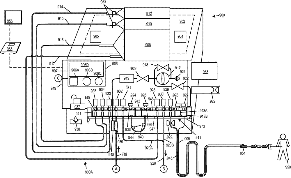
现在参考图8A和图9,图8A和图9显示了作为如本说明书中所述的完整的系统来一起操作的腹膜透析系统900和水净化系统901的示意图。腹膜透析系统900包括流体管理组900A。流体管理组900A与水净化系统901的流体回路耦接,其中,该水净化系统901包括永久模块952和包括过滤器媒体的可消耗组件以及管道组901A。腹膜透析系统900包括PD循环仪和透析液制备模块949,其包括控制以及许多永久硬件;可以将水净化系统互连到共享控制,因而单个用户接口面板906可用于针对治疗管理而控制这两者。Reference is now made to FIGS. 8A and 9 , which show schematic diagrams of a
PD循环仪和透析液制备模块949具有控制器907,其中,控制907具有用户接口面板906。用户接口面板具有控制件906A、906B、906C和显示器906D。用户接口面板906的控制和其他特征可以包括音频输出装置、LED灯、触摸屏输入以及可用于与数字电子控制系统交互的其他装置。用户接口面板906、控制件906A、906B、906C优选地是用颜色编码和形状区分的一小组明显地区分的控制件。The PD cycler and
流体管理组900A包括一次性的配合料容器908、电解质容器910和渗透剂浓缩液容器912,例如连接到各自的透析溶液汲取管线916、电解质汲取管线915、和渗透剂汲取管线914的袋子。配合料容器908优选是空的预先杀菌的弹性容器,其中,该容器被排空空气或流体并且永久附接到透析溶液汲取管线和配合料填充管线917,其中,配合料填充管线917用于向袋子增加流体并且透析溶液汲取管线916用于从袋子汲取内含物。电解质容器910和渗透剂浓缩液容器912分别存储电解质和渗透剂浓缩液并且还被永久附接到渗透剂和电解质汲取管线914和915。在无菌条件下预先附接并且提供容器和管线。配合料容器908最终充满无菌的水、渗透剂和电解质的混合物,以形成透析溶液处方。配合料容器908具有两个管线,而其他容器具有单个管线。可以用不可再开启的夹子953安装渗透剂容器912和电解质容器910。Fluid management set 900A includes
配合料容器908可以被配置为容纳用于单个腹膜透析填充循环的充足透析溶液或者其可以足够大以用于多个填充循环。因此,制备循环可以生成足以用于完整的治疗的透析液(例如包括多个排出-填充循环的夜间治疗循环)。
配合料容器908、电解质浓缩液容器910和渗透剂浓缩液容器912可以搁在由虚线所指示的加热器和/或秤902上。可以在加热器和/或秤902的表面上提供温度传感器904或905,以向用于控制加热器和/或秤902的控制器907提供温度信号。该控制器可以被配置为加热直接搁在加热器和/或秤902上的配合料容器908中的透析液。温度传感器904或905可以被定位为确保配合料容器908直接搁在温度传感器904或905上。大的配合料容器908(数升)中的自由对流的组合、配合料容器908的薄壁以及壁的柔软度助于确保用于反映配合料容器908的内含物的温度的、温度传感器904或905的读数。注意到虽然温度传感器904或905被显示为远离配合料容器908、电解质容器910和渗透剂浓缩液容器912定位,但是想到可以将其紧邻配合料容器908放置。
用由屏障节段842分离并且由泵管道片段944互连的两个阀头部941和946将汲取管线914、915和916和填充管线917连接到歧管模块911。阀头部941和946之间的流动仅经过泵片段944或者经过与泵片段944链接的管线之间的外部连接发生,如通过经由阀头部941和946以及汲取管线916和填充管线917流动经过配合料容器908。与蠕动泵致动器943以及阀致动器929、930、928、931、932、933、934和935结合的歧管模块911提供并且调节所选择的多对管道管线914、915和916,填充管线917、排出管线920A和920B、产物水管线919和患者管线945之间的流体的流动。歧管模块911还具有传感器区域936和相应的压力变换器924和925,以产生反映泵管道片段944的任意一侧上的压力的压力信号。
歧管模块911还具有室913A和913B和相应的压力变换器926和927以产生用于反映患者管线945的近端和远端上的压力的压力信号。压力室913B连接到气动信号管线909,气动信号管线909相应地连接到压力吊舱951,压力吊舱951被配置为经过气动信号管线909向室913B传输患者管线945远端中的压力。室913A与患者管线945的靠近室913A的末端连通并且向变换器926传送压力以生成用于表示患者管线945的近端处的压力的信号。连接控制器907以控制蠕动泵致动器943和阀致动器929、930、928、931、932、933、934和935并且经过927接收来自压力变换器924的压力信号。可以借助可以具有如附图中所示的铰链和门闩的门973来紧靠着阀致动器929、930、928、931、932、933、934和935按压歧管模块911[注释:见用于关于如何实际配置其的最新思想的背景材料]。
一个可替换的实施方式用直接压电变换器代替压力吊舱951,这避免了在该实施方式中对于室913B的需求。直接压电变换器可以采取可浸没应变仪的形式,其中,该可浸没应变仪是可体积模式(bulk-mode)变形的,以便提供负的和正的压力值或者根据需要提供负的和正的压力值中的任意一个。电气导线和无线信道可以向控制器907传送压力信号。可以将该变换器与用于患者通道的连接器集成。可替换地,该直接压电变换器可以是压力导管例如如本文任意地方所述的一个与压力导管集成的直接压电变换器。An alternative embodiment replaces
歧管模块911具有相应的方框形阀头部941和946。每个头部具有多个由阀致动器929、930、928、931、932、933、934和935中相应的一个阀致动器所致动的阀结构。阀致动器929、930、928、931、932、933、934和935可以是电磁锤、线性马达、气动锤或用于应用力以按压在相应的一个阀头部(在140处指示的阀中的一个)上的任意合适的设备。参考图8B和8C,阀140被显示为处于开启位置(图8B)和闭合位置(图8C)。致动器(如929)的柱塞136垂直地移动以在膈膜134上施加力以将膈膜134闭合在开口132上。通过使用吻合端口133将管道131绑定到头部壁135来附接管道131,以允许管道131能够接收及密封到头部壁135上。将管道131密封到头部壁135上以防止当将膈膜134闭合在开口132上时在管道的内腔之间的流动。因此仅可以通过操作致动器来相应地驱动柱塞13来可选择性地接入阀头部941和946的内部容积130。通过选择打开一对致动器,流动可以经过与被激活打开的该对致动器相对应的两个管道的内腔之间的阀头部的内部容积而发生。可以由弹簧(或其他装置)常闭该致动器,并且仅当该致动器被赋能时才开启该致动器。可替换地,它们可以常开。The
产物水管线919连接到水净化系统(管线继续到用图9中相同的接合符号A所标记的管线)。排出管线920连接到水净化系统(管线继续到用图9中相同的接合符号B所标记的管线)。可以提供由连接符号C指示的(可以有线或无线的)控制管线连接,以将内部中央控制器959连接到控制器906以允许来自控制器906的命令用于控制水净化系统901。注意到,可替换地,数据总线或等效的通信网络如线束或无线网(未显示)可以代替控制器959而给予控制器906到水净化系统901的全部传感器和最终控制器和致动器的直接通道,因而水净化系统仅仅是腹膜透析系统900的组件。在其他实施方式中,水净化系统可以作为独立的设备来操作并且包括它自己的用户接口和控制件,以供应用于其他功能如血液透析的产物水。在实施方式中,可以将用户接口906的功能合并或包括在无线输入设备如秤955或便携式用户接口模块956中。The
提供无菌过滤器939以无菌过滤在产物水管线919中提供的产物水。在一批透析溶液的制备期间、之前或之后,可以通过执行始沸点或压力下降测试来测试过滤器的泄露。德尔塔压力变换器(由膈膜分离的两个压力传感器)或单个压力变换器在浸湿膈膜的空气侧上。在本实施方式中,位于919处的变换器919测量与无菌过滤器939的浸湿膈膜的空气侧连通的空气室948中的压力。压力变换器919用于检测压力下降(或者在其他实施方式中跨膈膜的压力TMP下降分布)以确定过滤器完整性是否处于期望的限制内。在本实施方式中,空气泵917经过过滤器921汲取空气并且经过控制阀923和压力传感器选择性地泵送空气。泵917可以使用压力调整的阀917连续地运行,以维持到阀923和阀922的希望的压力供应,其中,可以选择性地开启阀923和阀922以将空气传递到室913B和/或948中。将空气流到室948中的目的在于执行在制造了一批透析溶液之后完成的始沸或压力下降测试并且确认在产物水的传递期间维持过滤器完整性。完成将空气吹到室948中的目的在于重设压力吊舱951的空气侧室的容量。可以从压力吊舱选择性地泄露空气或者将空气选择性地泵送到压力吊舱中,以避免横膈膜压靠在它的行进范围中的一侧或另一侧上,从而防止伪读取。总而言之,由控制器907控制阀918、923和922(通过旁路流动)调节压力,并且选择性地允许空气流动到室913B和/或945以用于所述功能。A
现在具体参考图9,水净化系统901经过应用粗糙颗粒和/或沉淀阱944的第一阶段来净化水。第二阶段应用碳过滤器。第三阶段使用紫外线灯来对水去污染。第四阶段使用逆渗透。第五阶段使用碳抛光过滤器,其后紧接着消电离过滤的第六阶段。第七和最终阶段是使用一对串联的超滤器的杀菌阶段,其中,提供该超滤器以防止最终的产物水的伴生污染。Referring now specifically to FIG. 9 , a
永久过滤子系统952包括泵900、紫外线灯982、传感器模块984和985、用于逆渗透系统的自动截止阀988、压力传感器992、981、953、989以及阀991和993。
来自排出管线920的排出流体经过连接器978并且进入一对分别用于检测并且测量导电率和温度的传感器模块984和985。传感器模块984和985提供冗余,以作为针对其中一个模块中的错误的保护。可以例如通过强制这样一种要求来确保安全性,其中该要求是:串行互连的传感器模块984和985提供总是一致的信号,并且在不一致的情况中,根据操作状态可以生成警报或者采取一些其他行动。尿素传感器953可用于生成用于指示尿素的水平的信号。在一些模式中排出管线携带用过的透析液并且尿素内含物可以被记录或者否则用于根据已知的原理确保血液肾透析患者的正确治疗。尿素水平可以显示在显示器906D上或者记录在控制器907的数据存储器中或者还或者可替换地存储在因特网服务器上或者外部数据存储器(未显示)上。在各个位置处的止回阀987防止回流。在排出管线中的一个止回阀987可以用于放置回流到腹膜透析系统900中。另一个止回阀987防止排出流体回流到逆渗透过滤器975中并且另一个防止从逆渗透过滤器975流出的预先过滤的水逆向流动。另一个止回阀987防止进入粒子过滤器994的系统上游的原生水逆向流动。Exhaust fluid from
除了传感器模块984和985之外,或者可替换地,提供流体数量测量模块。原生水经过连接器978和止回阀987进入水净化系统901并且进入粒子过滤器994。已过滤的水传递经过压力控制阀996,经过气孔999到达用于将气孔999连接到永久过滤子系统952的连接器978。速度已调节的泵990经过阀汲取水。分别由传感器992和989测量泵990的上游和下游的压力。旁路阀991允许再次流通水以控制压力。由控制器955控制旁路阀991以调节离开泵990的压力。In addition to
自动截止阀988利用相应的废水连接、产物水连接和给水连接978,将水供给到碳和RO子系统997。给水经过用于向控制器955应用导电率信号的导电率传感器977并且随后经过激活的碳过滤器床。Automatic shut-off
在传递经过RO膈膜975之后,产物水流动经过止回阀987经过管线957到达压力传感器981,经过自动截止阀988到达紫外线过滤器,其中,在该紫外线灯之后产物水经过连接器978离开永久过滤子系统952。用于从永久过滤子系统952接收产物水的连接器978是包括碳963、隔离床去离子过滤器959(每个具有阳离子床965和阴离子964)和混合床去离子过滤器966的一次性过滤器模块970的一部分。一次性过滤器模块970还包括一对具有气孔956的分离的超滤器958。导电率传感器968A检测污染物的早期泄露,其中,该早期泄露可以被控制器955用于生产需要改变过滤器模块970的指示。可以经由用户接口面板906或者一个独立的用户接口面板输出过滤器模块970到期的指示。超滤器958被分离,以杀菌并且防止伴生污染。止回阀969防止逆流。当首次连接过滤器模块970时烧断保险丝。控制器955防止具有烧断的保险丝的过滤器模块970的重新连接,从而防止以前使用的过滤器模块970的重新使用。湿度传感器938连接到控制器955并且当被泄露浸湿时生成被应用于控制器955的信号。After passing through the RO diaphragm 975, the product water flows through the
图10显示了腹膜透析系统900被重配置为使用预先杀菌的容器1002中的制备透析液的腹膜透析系统。与系统900不同,本系统不需要水净化系统901来工作。将新鲜透析溶液袋1002连接到管道组1000,其中,管道组1000被配置为允许PD循环仪和透析液制备模块949用于制备的袋装透析液。除了注意到在一些实例中由控制器907的命令信号再次分配致动器929、930、928、931、932、933、934和935的功能之外,将不再描述PD循环仪和透析液制备模块949。FIG. 10 shows a
如图可见,管线1010、1011、1012和1013将透析溶液袋1002连接到歧管模块911。将至少一个透析溶液袋1002附接到两个阀头部941和946中的不同的阀头部,以允许袋之间的透析溶液的传递,这相应地允许管道组1000的填装和其他功能。还注意到,将管线1010耦合到管线945以允许来自阀头部941和946中的任意一个的流体被泵送到患者管线945中。由该配置使能的功能包括例如允许流体从任意其他透析溶液袋1002被传送到在1020处所指示的可以搁在加热器903上的透析溶液袋1002中的一个。然后,在将袋1020清空之后,可以从其他袋1002中的一个袋传递流体以填充该袋1020,并且袋1020在注入之前被加热。管道组1000和阀头部941和946的检查弄清楚仅由929、930、928、931、932、933、934和935的合适的顺序使能这些功能。每个透析溶液袋1002具有不可再开启的夹子1005、无针端口1007以及在袋1002和管道组1000上的匹配连接器1006和1007。As can be seen,
图11显示了用于制备任意一个前述腹膜透析系统的方法的概述。图11的流程图的左侧显示用于使用袋装的透析液的系统的方法并且右侧是用于制备透析液的系统如系统900。首先悬挂第一新袋S10(在实施方式902中将一个袋放置在加热器上)。然后将筒或管道组加载到循环仪上S12。在袋装流体系统中,将新袋连接到管道组或筒S14并且连接排出和患者管线S16。加热器上的袋1020用于第一循环并且可以被预先填充。在一个可替换的实施方式中,加热器上的袋最初是空的并且形成流体回路1000的预先附接的部分。稍后在第一循环之后,加热器上的袋可以是空的并且从一个或多个其他袋1002填充该袋。加热器上的袋1020无论是否被填充都用于通过经过流体回路和患者管线流动透析溶液S19来填装S17。在填装期间可以经过排出以导向流体并且将该流体如上所述用于测试导电率。Figure 11 shows an overview of the method used to prepare any of the aforementioned peritoneal dialysis systems. The left side of the flowchart of FIG. 11 shows a method for a system using bagged dialysate and the right side is a system, such as
在S18处,可以执行自测试程序以例如完成泵校准,检查压力范围,在过滤器膈膜上执行始沸点或压力下降测试等等。然后将患者通道连接到患者管线和排出循环S22,紧接着执行填充循环S24。可以重复排出循环和填充循环,直到治疗完成检查S26指示已经执行了排出循环和填充循环的一个完整的组为止。可以排出袋1002中的剩余的流体并且可以断开并且处置通道、袋和流体组S30和S32。At S18, a self-test routine may be performed to eg complete pump calibration, check pressure ranges, perform bubble point or pressure drop tests on filter diaphragms, and the like. The patient access is then connected to the patient line and drain cycle S22, followed by a fill cycle S24. The drain and fill cycles may be repeated until the treatment complete check S26 indicates that a complete set of drain and fill cycles have been performed. The remaining fluid in the
仍然参考图11,一种用于腹膜系统900的方法可以制备透析液的每个配合料。在该方法中,流体管理组900A被加载到该系统上,包括将一次性配合料容器908、电解质浓缩液容器910和渗透剂浓缩液容器912可以搁在由虚线所指示的加热器和/或秤902上S40。加载流体管理组900A的包括歧管模块911的剩余部分,并且关闭门973以靠着阀致动器929、930、928、931、932、933、934和935夹住歧管模块911。可替换地,可以加载任意其他合适的流体回路例如图8D和8E的实例以及它们的变形。在S16处,连接患者管线和排出管线并且在S46、S48处填装回路900A并且如果需要则冲刷流体回路900A。填装S50用于连接管线的一次性配合料容器908、电解质浓缩液容器910和渗透剂浓缩液容器912并且执行S52配合料制备和过滤器测试。填装S19患者管线并且连接S20患者通道。可以重复排出循环和填充循环,直到治疗完成检查S26指示已经执行了排出循环和填充循环的一个完整的组为止。清空S58并且断开S60一次性配合料容器908、电解质浓缩液容器910和渗透剂浓缩液容器912并且在S32处断开该排出。Still referring to FIG. 11 , one method for the
图12示出了图11的S50中的过程,其中,在该过程中填装用于连接管线的一次性配合料容器908、电解质浓缩液容器910和渗透剂浓缩液容器912。在S50B处,经过传导单元填充并且排出渗透剂管线914,直到在S50A传导单元显示流体出现在哪个点为止,在S50D同样对于电解质管线913完成这个直到在S50C处由导电率传感器检测到电解质为止。回想起来导电率传感器984和985可以通过检测连接到水净化系统901的排出管线中的流体特性来用于该目的。接下来,在S50F纯净的产物水冲刷用于填装排出管线的任意浓缩液流体,并且填装产物水管线919直到时间间隔S50G消逝为止,并且确认产物水的导电率。然后填装配合料填充管线919并且用200ml或更多的水填充配合料容器908S50G。将水经过配合料容器汲取管线916排出配合料容器908,直到已经去除100ml为止S50J。在一个实施方式中,此时可以在配合料容器908中应用真空,以优化流体汲取循环中的可重复性。FIG. 12 shows the process in S50 of FIG. 11 , in which the
图13示出了图11的S52中的过程,其中,在该过程中由腹膜透析系统900或类似的系统制备透析液的配合料。在S52B,用产物水填充配合料容器908直到移动了1500ml(这在S52A处检测)为止。该数量仅仅是个实例并且在不同的实施方式中可以改变。渗透剂浓缩液然后被52D汲取并且泵送到配合料容器908中直到配合料容器的总混合容量是1550ml为止52C。可以用测容量或比重计量或任意其他合适的方式确认配合料容器的填充状态。如上文所讨论的,在其他实施方式中,或者在本实施方式中,除了通过检测进行的控制和确认之外,或者可替换地,在形成如上所述的本系统的目标处方和比率计量的配比方面而言最重要的流体比率确保实现电解质和渗透剂比率和稀释。接下来,在S52F处,将电解质浓缩液汲取并且泵送到配合料容器908,直到配合料容器的总混合容量是1650ml为止52E。如上所述,在此时可以选择性地执行紧接着导电率测试的混合步骤。通过在一个时间段期间S52J或者基于预先限定数量的泵循环,经过管线916和917汲取并且填充来混合配合料容器908的内含物。可以多次发生该混合,其中,在混合循环期间具有休息间隔。其后可以紧接电解质的附加补充,以实现希望的处方。将剩余的产物水泵送到配合料容器908中S52H,直到在S52G处实现填充数量为止。在S52C、S52E、S52G中的每一个处,可以例如通过经过水净化系统901的排出而自动地排出少的样本,来检查配合料容器908的内含物的导电率。然后通过在一个时间段期间S52J或者基于预先限定数量的泵循环,经过管线916和917汲取并且填充来混合配合料容器908的内含物。可以多次发生该混合,其中,在混合循环期间具有休息间隔。确认导电率并且该程序结束(S52结束),或者如果导电率测试失败(未实现透析液导电率)则输出警报S52L。最后,通过经过膈膜泵送空气,利用始沸点或压力下降测试来测试无菌过滤器完整性S61。FIG. 13 shows the process in S52 of FIG. 11 , in which a batch of dialysate is prepared by the
图14显示了图11的S61中的过程的细节。在S61B处,阀923开启,918闭合并且由压力传感器919记录的气压增加,直到在S61A处压力达到预先确定的压力(例如45帕)为止,然后关掉气泵并且阀923闭合。在S61D处,在一个时间间隔例如在S61C处的3分钟期间监视如由压力传感器919指示(并且可用于生成下降曲线)的压力。如果该压力下降到门限(例如40帕)之下,则在S16F输出警报并且否则(S61C)阀918和923开启直到在S61E检测到919处的压力低于门限例如100mm Hg为止。FIG. 14 shows details of the process in S61 of FIG. 11 . At S61B,
图15显示了图11的S19中的过程的细节。图16显示了图11的S58中的过程的细节。FIG. 15 shows details of the process in S19 of FIG. 11 . FIG. 16 shows details of the process in S58 of FIG. 11 .
图17A到17T示出了根据前述的系统实施方式的腹膜透析系统的方法和基础结构。配合料容器202具有配合料容器填充管线222和配合料容器排出管线224。渗透剂浓缩液容器204具有渗透剂浓缩液排出管线220。电解质浓缩液容器206具有电解质浓缩液排出管线218。净化水源216如净水厂具有净化水源供应管线223,其中,该净化水源供应管线223向由无菌水供应管线226所连接的无菌过滤器210给水,其中,无菌水供应管线226用于将无菌过滤器210连接到歧管/泵送配置208。主排出228向导电率传感器212发送废的和填装的流体并且经过最终排出管线230放出。患者管线234连接到歧管/泵送配置208。17A to 17T illustrate the method and basic structure of a peritoneal dialysis system according to the aforementioned system embodiments. The batch container 202 has a batch
下文的描述应用于通用PD系统,并且可以根据各种设计和技术方法中的任意一个来配置元件。歧管/泵送配置208可以例如使用横膈膜配置或离心泵来泵送流体并且包括各种种类的流动控制,包括永久阀、流动开关、管线钳等等。配合料容器202、渗透剂浓缩液容器204和电解质浓缩液容器206可以是刚性的或袋型的容器并且可以是一次性的或者具有消毒工厂的永久性的。The following description applies to a general PD system, and elements may be configured according to any of various design and technical approaches. The manifold/
图17A显示了渗透剂浓缩液排出管线220、歧管/泵送配置208经由经过如上所述的导电率传感器212的主排出228和最终排出管线230的初始填充。歧管/泵送配置208被配置为提供所显示的流量,并且提供控制器以基于下一个配置而改变。在图17B中,歧管/泵送配置208被配置为从电解质浓缩液容器206流动电解质浓缩液,其中,电解质浓缩液容器206经由经过导电率传感器212的主排出228和最终排出管线230填装电解质浓缩液。在图17C中,由歧管/泵送配置208经过净化水源供应管线223、经过无菌过滤器210、经过226来移动水并且经过导电率传感器212经由主排出228和最终排出管线230来移出水,从而从歧管/泵送配置208和主排出228和最终排出管线230冲刷出浓缩液。在每个阶段,由导电率传感器212测量导电率并且将导电率与参考范围比较。如果值在该参考范围之外,则停止生产并且生成错误消息。Figure 17A shows the initial filling of the osmotic agent
图17D显示了配合料容器202的初始填充。由歧管/泵送配置208经过净化水源供应管线223、无菌过滤器210、和无菌水供应管线226将净化的水泵送到配合料容器202中直到传递了预先限定的最小容量(例如200ml)为止。渗透剂浓缩液排出管线220和电解质浓缩液排出管线218如填充模式所显示地保持被填装。接下来,在图17E中,由歧管/泵送配置208经过导电率传感器212经由主排出228和最终排出管线230排出配合料容器202的一些内含物(例如100ml),并且根据结果继续导电率确定和后续的控制处理(停止和警报)。在图17E中,歧管/泵送配置208被配置为通过经过无菌过滤器210和无菌水供应管线226从净化水源216汲取水并且最终经由配合料容器填充管线222进入配合料容器202,来部分地填充歧管/泵送配置208。配合料容器排出管线224、渗透剂浓缩液排出管线220和电解质浓缩液排出管线218向主排出228和最终排出管线230一样保持被填装。Figure 17D shows the initial filling of the batch container 202. Purified water is pumped by manifold/
在图17G中,由歧管/泵送配置208汲取并且经由经过导电率传感器212的主排出228和最终排出管线230排出来自配合料容器202的样本。再次由导电率传感器212验证流体特性及通过或报警。在图17H中,由歧管/泵送配置208经由渗透剂浓缩液排出管线220从渗透剂浓缩液容器204汲取渗透剂,并且经过配合料容器填充管线222将渗透剂泵送到配合料容器202中。在图17J中,由歧管/泵送配置208从配合料容器202汲取样本并且经由经过导电率传感器212的主排出228和最终排出管线230将该样本排出。再次由导电率传感器212验证流体特性及通过或报警。In FIG. 17G , a sample from batch container 202 is drawn by manifold/
在图17K中,由歧管/泵送配置208经由电解质浓缩液排出管线218从电解质浓缩液容器206汲取电介质,并且将电介质经由配合料容器填充管线222传递到配合料容器202。在图17L中,由歧管/泵送配置208从配合料容器202汲取样本并且经过导电率传感器212经由主排出228和最终排出管线230将该样本排出。再次由导电率传感器212验证流体特性及通过或报警。在图17M中,由歧管/泵送配置208经过净化水源供应管线223、经过无菌过滤器210、经过226来汲取水,并且经由配合料容器填充管线222将水传递到配合料容器202。在图17N中,由歧管/泵送配置208从配合料容器202汲取样本并且经过导电率传感器212经由主排出228和最终排出管线230将该样本排出。再次由导电率传感器212验证流体特性及通过或报警。In FIG. 17K , electrolyte is drawn from electrolyte concentrate container 206 via electrolyte
图17P显示了这样一种流体混合配置,其中在该流体混合配置中歧管/泵送配置208被配置为循环经由配合料容器填充管线222和配合料容器排出管线224经过配合料容器202的流体。这针对预先限定的时间周期、预计的流体循环数量或泵循环数量来完成。在图17Q中,由歧管/泵送配置208从配合料容器202汲取最终透析产物的样本并且经过导电率传感器212经由主排出228和最终排出管线230将该样本排出。再次由导电率传感器212验证流体特性及通过或报警。如果需要调整流体配方,则可以增加少量的渗透剂浓缩液或电介质浓缩液或者稀释用水并且重复该测试直到达到希望的配方为止。Figure 17P shows a fluid mixing arrangement in which the manifold/
图17R显示了由歧管/泵送配置208经过配合料容器排出管线224汲取并且流出患者管线234以填装患者管线234的流体。在图17S中,用于患者214的通道已经被连接到患者管线234并且执行排出操作,其中,在该排出操作中由歧管/泵送配置208经过患者管线234从患者214排出用过的透析液并且经过导电率传感器212经由主排出228和最终排出管线230传递出去。检测的导电率和压力改变可用于诊断问题例如如上所述的腹膜的渗透率、感染等等。图17T显示了患者填充循环,其中,在该患者填充循环中由歧管/泵送配置208从配合料容器202汲取流体并且将流体泵送到患者管线234中并且泵送到患者214中。FIG. 17R shows fluid being drawn by manifold/
在图17A到17T的实施方式中,歧管/泵送配置208可以包括控制器、用户接口、阀、一个或多个泵、传感器、流速传感器、测容量的位移传感器和/或其他组件以实现所述功能。In the embodiment of FIGS. 17A through 17T , the manifold/
在任意前述实施方式中,渗透剂浓缩液可以包括允许通过传导单元来测量电解质浓度来确定渗透剂的数量或浓度的预先限定份额的电解质浓缩液。通过基于用渗透剂浓缩液所传递的已知数量来配比电解质浓缩液以实现最终电解质浓度。In any of the preceding embodiments, the osmotic agent concentrate may comprise a pre-defined fraction of the electrolyte concentrate that allows measurement of the electrolyte concentration by the conduction cell to determine the amount or concentration of the osmotic agent. The final electrolyte concentration is achieved by dosing the electrolyte concentrate based on known quantities delivered with the osmotic agent concentrate.
图18显示了根据本文公开的主题的实施方式的控制系统。控制器830可以接收PD系统838中的任意点的传感器信号包括导电率、温度和流动速率。控制器可以应用致动器控制信号以利用可变再循环旁路管线或可变管线内阻力如流动调节器阀来调节泵或等效流动速率调节器(如固定速率泵)的速度。以调节后的速率将从PD系统838提供的流体传递到腹膜管线842,其中,腹膜管线842可以包括用于流出和返回流体的单个管线或者一对管线,其中,该对管线中的每个管线分别用于流出和返回流体。压力传感器834生成用于指示流出腹膜管线或者在两个方向中传递流体的腹膜管线中的远端点处的压力的信号。附加的压力传感器可分别用于流出和返回管线。数据存储器836可以存储一个或多个治疗分布,该一个或多个治疗分布专用于包括流体回路的一次性单元(其可以根据流体回路的特性而改变),其专用于具体的患者或患者类别或其他需求。Figure 18 shows a control system according to an embodiment of the herein disclosed subject matter. The controller 830 may receive sensor signals including conductivity, temperature, and flow rate at any point in the PD system 838 . A controller can apply an actuator control signal to adjust the speed of a pump or an equivalent flow rate regulator (eg, a fixed rate pump) using a variable recirculation bypass line or a variable inline resistance such as a flow regulator valve. Fluid provided from PD system 838 is delivered at an adjusted rate to
可以从附接到一次性单元的数据存储器841获得在数据存储器836上存储的压力分布数据或者该数据可以基于识别关于该数据存储器841的信息从服务器下载。可替换地,可以将压力分布数据周期性地存储在836上,并且在治疗期间从控制器的用户接口选择将要用于治疗的具体数据例如用于经过该用户接口所识别的具体患者的数据,其中从患者专用的治疗数据的库获得该患者的分布数据。该压力分布数据可以包括用于表示压力传感器834的点处的最大压力的单个压力值,其中,该单个压力值指示最大压力并且作为关于如根据任意一个前述实施方式所述的控制器830所控制的泵840的泵速率的限制。压力分布数据可以包括用于表示腹膜透析填充循环的相应阶段的多个压力值。压力值可以例如将容量与压力或者泵旋转的数量与压力相关联,因此定义分布。在一个实例中,该速率可以逐步地升高到最大值并且随后逐渐地减缓以快速的平衡吞吐量与患者舒适度的希望。The pressure profile data stored on the
图19显示了根据本文公开的实施方式的流体路径和致动器布局。本实施方式显示关于上述实施方式的变形。例如,独立的填充管线861和排出管线862连接到患者(单内腔或双内腔腹膜导管)。在填充管线内提供无菌滤波器860。可以例如在854和/或855所示处提供一个或多个流动传感器,其中,该一个或多个流动传感器可以如上所述用于错误条件检测或者用于实现校准程序以得出泵循环到净位移质量的转换或者每个流体路径各自的容量。相应的阀G1、P1、P1、P2、S1、S1、W1和E1控制回路中的流体的流动。泵858移动回路中的流体。下文的表格显示了用于由图19所覆盖的实施方式的操作程序的实施方式。可以将这些特征中的任意一个组合在任意一个前述实施方式中以形成附加的实施方式。例如,可以在图6A到6K或7A到10或17A到17T的实施方式中提供一个或多个流动传感器。还可以修改方法实施方式以增加上文概述的校准程序。Figure 19 shows a fluid path and actuator layout according to embodiments disclosed herein. This embodiment shows a modification of the above-described embodiment. For example,

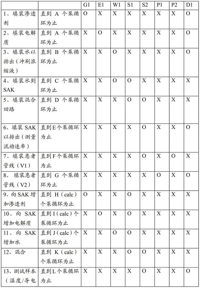
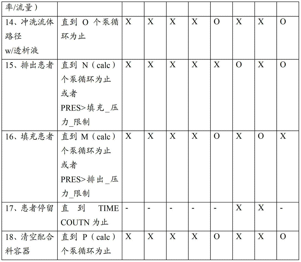
在第二列中,泵操作、字母A、B、C、D等等涉及预先限定的值。蠕动泵可以例如每被泵送2ml旋转一次,因而该值可以对应于泵送的流体的数量。被标记为阀状态的列涉及图19中所标记的阀的状态,其中,X涉及闭合情况并且O涉及开启情况。泵操作列中的项(calc)指示根据从如上所述的校准获得的参数调整泵循环的数量。In the second column, pump operation, letters A, B, C, D, etc. refer to predefined values. The peristaltic pump may eg rotate once every 2 ml pumped, so this value may correspond to the amount of fluid pumped. The column labeled Valve Status relates to the status of the valves marked in Figure 19, where X relates to the closed condition and O relates to the open condition. The entry (calc) in the pump operation column indicates the number of pump cycles to adjust according to the parameters obtained from calibration as described above.
在任意一个所公开并且/或者要求的、将配合料容器清空的方法、控制或系统实施方式中,可以在一个时间周期期间将负的泵送压力应用于容器以确保完全清空。并且,在任意一个所公开并且/或者要求的方法、控制或系统实施方式中,配合料容器可以位于带角度的底座上,其中,该配合料容器的排出开口位于最低点,这同样助于完全清空配合料容器。通过提供用于挤或振动配合料容器和/或其他流体容器以助于确保水不被截留的机制,可以形成其他实施方式。In any of the disclosed and/or claimed method, control or system embodiments for emptying a batch container, negative pumping pressure may be applied to the container during a period of time to ensure complete emptying. Also, in any of the disclosed and/or claimed method, control, or system embodiments, the batch container may be positioned on an angled base, wherein the discharge opening of the batch container is at the lowest point, which also facilitates complete Empty the batch container. Other embodiments may be formed by providing a mechanism for squeezing or vibrating the batch container and/or other fluid container to help ensure that water is not trapped.
在任意一个前述歧管实施方式中,可以如同图7A、7B和8A中的实施方式,将排出管线分裂给泵管道的两侧上的阀,或者可以如同图10和19,将患者管线分裂给泵管道的两侧上的阀。当分裂排出管线时,可能需要倒转泵,以便填充并且排出患者的腹膜。通过分裂患者管线,可以构造并且操作歧管和泵,因而根据这样一种实施方式泵仅需要在单个方向中运转以提供所有需要的功能,其中,在该实施方式中:(1)水、治疗流体组件和一个配合料容器出口都经由各自的控制阀连接到泵入口,并且配合料容器入口和排出管经过各自的控制阀连接到泵出口;并且(2)患者管线经过各自的控制阀连接到泵入口和出口。提供在单个方向中运行泵,可以更好地维持从泵循环到所传递的流体的转换的重复性。在一个可替换的实施方式中,由独立的泵管线从患者排出流体。这可以通过双内腔腹膜管线或单内腔管线来完成。In any of the foregoing manifold embodiments, the discharge line can be split into valves on both sides of the pump tubing as in the embodiment in FIGS. 7A, 7B and 8A, or the patient line can be split into Valves on both sides of the pump piping. When splitting the drain line, it may be necessary to reverse the pump in order to fill and drain the patient's peritoneum. By splitting the patient line, the manifold and pump can be constructed and operated so that the pump only needs to operate in a single direction to provide all required functions according to an embodiment in which: (1) water, therapy Both the fluid assembly and a batch container outlet are connected to the pump inlet via respective control valves, and the batch container inlet and discharge tubing are connected to the pump outlet via respective control valves; and (2) the patient line is connected to the pump outlet via respective control valves; Pump inlet and outlet. Provided that the pump is run in a single direction, the repeatability of switching from pump circulation to the fluid being delivered can be better maintained. In an alternative embodiment, fluid is drained from the patient by a separate pump line. This can be done with a double lumen peritoneal line or a single lumen line.
在任意一个前述实施方式中,可以使用独立的填充管线和排出管线来替代单个填充/排出管线。在具有独立的填充管线和排出管线的实施方式中,可以仅在填充管线上,仅在排出管线上携带压力吊舱或者可以在填充管线和排出管线上都提供压力吊舱。对于腹膜治疗管线的其它压力测量实施方式也是这样。如将显而易见的,压力测量能力可用于用过的透析液特性的检测并且用于填充流动速率的调整以及本文所述的其他目的。In any of the foregoing embodiments, separate fill and drain lines may be used instead of a single fill/drain line. In embodiments having separate fill and discharge lines, pressure pods may be carried on the fill line only, on the discharge line only or may be provided on both the fill and discharge lines. The same is true for other pressure measurement embodiments of the peritoneal therapy line. As will be apparent, the pressure measurement capability can be used for detection of spent dialysate properties and for adjustment of fill flow rate, among other purposes described herein.
在本实施方式以及任意一个其他实施方式中,可以排出足够数量的流体以便接触导电率传感器以形成可靠的读数。可以例如使用25到100ml范围中或者优选地50到70ml范围中的数量.In this embodiment, as well as any of the other embodiments, a sufficient amount of fluid can be expelled to contact the conductivity sensor to form a reliable reading. Quantities in the range of 25 to 100 ml or preferably in the range of 50 to 70 ml can be used, for example.
在任意一个所述实施方式中,渗透剂可以是或者包括葡萄糖、左旋肉碱、甘油、艾考糊精或任意其他合适的剂。此外,用于组合成腹膜透析容易的组分可以改变数量,并且可以通过实施方式的直接修改从单个浓缩液组分或任意其他数量的浓缩液组分构成任意一个所述实施方式。缓冲剂(例如醋酸盐、重碳酸盐、乳酸盐)可以例如与电解质分离,其中该电解质可以与渗透剂分离。In any of the described embodiments, the osmotic agent can be or include dextrose, L-carnitine, glycerol, icodextrin, or any other suitable agent. Furthermore, the components used to combine into peritoneal dialysis can vary in number and any one of the described embodiments can be constructed from a single concentrate component or any other number of concentrate components by direct modification of the embodiment. Buffering agents (eg acetate, bicarbonate, lactate) can eg be separated from the electrolyte, where the electrolyte can be separated from the osmotic agent.
在应用稀释流体的直接附接的任意一个所公开的实施方式例如图10的实施方式中,可以将无菌过滤器预先安装在流体管线上(例如管线1010、1011和1012)以防止接触污染导致流动到患者的流体的污染。In any of the disclosed embodiments employing direct attachment of dilution fluids, such as the embodiment of FIG. Contamination of fluid flowing to the patient.
在任意一个所公开的实施方式中,当存在无流动、低速流动条件时可以生成腹膜管线的近端和远端的压力信号。可以将其控制为发生在治疗的准备或质量期间中的特定时刻,以生成管线中的静态水头的指示。例如,如果患者掉下床并且出现近端与远端之间的突然高度差,则可以检测到压力差。该检测可以触发警报或其他输出,并且可以例示机器状态的改变例如关闭。在低速流动或无流动期间来自超限压力差的另一个推论是系统的异常建立。在实施方式中,可以由假定的系统配置来管控从泵循环到总传递的流量的转换,其中,该假定的系统配置可以包括腹膜管线的远端与近端之间的的高度差的特定范围。下文的表格显示了一些可能的行为。In any of the disclosed embodiments, pressure signals at the proximal and distal ends of the peritoneal line can be generated when no-flow, low-velocity flow conditions exist. This can be controlled to occur at specific times during the preparation or quality of treatment to generate an indication of static head in the line. For example, if a patient falls out of bed and there is a sudden height difference between the proximal and distal ends, a pressure differential can be detected. This detection may trigger an alarm or other output, and may illustrate a change in machine state such as shutting down. Another inference from excessive pressure differentials during periods of low or no flow is abnormal build-up of the system. In embodiments, the transition from pump circulation to total delivered flow may be governed by an assumed system configuration, which may include a specific range of height differences between the distal and proximal ends of the peritoneal line . The table below shows some possible behaviors.


在上文的表格中,由字母识别的范围可以表示压力分布,其中,该压力分布是在渐进的过程期间改变的压力值(上限或下限或者刚刚好的上限或刚刚好的下限)。压力范围C可以随着泵循环的数量一起升高。该范围数据可以存储在控制器的存储器中并且/或者可以存储在可替换的管道组的存储器设备中并且/或者可以从远程服务器读取或者由任意其他合适的系统传递。压力范围数据可以与具体的管道组模型、治疗类型和/或患者相对应,并且选择可以是自动的或者经过用户接口来手动地做出的。术语误配置可以涉及结、障碍、泄漏、连接断开或其他类型的管线问题。在该表格中,任何地方的报警或其它输入可以被指示为行动,这可以包括或者在可替换地指示用户采取一些行动来核实问题或者采取什么行动的详细解释。例如,如果指示了连接的误操作,则。In the tables above, the ranges identified by letters may represent pressure profiles, where the pressure profile is a pressure value (upper or lower or just right upper or just right lower limit) that changes during the progressive process. The pressure range C can increase with the number of pump cycles. The range data may be stored in the memory of the controller and/or may be stored in a memory device of an alternate pipe set and/or may be read from a remote server or communicated by any other suitable system. Pressure range data may correspond to a specific tubing set model, therapy type, and/or patient, and selection may be made automatically or manually via a user interface. The term misconfiguration can refer to knots, snags, leaks, broken connections, or other types of pipeline problems. Anywhere in the form, an alert or other input may be indicated as an action, which may include or alternatively instruct the user to take some action to verify the problem or a detailed explanation of what action to take. For example, if misoperation of the connection is indicated.
在任意一个所公开的实施方式中,可以将远端压力传感器放置在腹膜循环仪机器中或者在导向患者并且靠近该机器的管道组上。可以将该远端压力传感器靠近患者放置或者放置在管道组上或者腹膜导管中。远端压力传感器还可以与管道组分离并且位于腹膜中。在该实施方式中,压力传感器管线可以附接到管道组。例如管道的金属化的表面或者混合挤压(电线绝缘并且管道被混合挤压)或在沿着管道的点处简单地附接到管道。In any of the disclosed embodiments, the distal pressure sensor can be placed in the peritoneal cycler machine or on the tubing set leading to the patient and proximate to the machine. The distal pressure sensor can be placed close to the patient or on the tubing set or in the peritoneal catheter. The distal pressure sensor may also be separate from the tubing set and located in the peritoneum. In this embodiment, a pressure sensor line may be attached to the tubing set. For example a metallized surface of the pipe or a co-extrusion (the wire is insulated and the pipe is co-extruded) or simply attached to the pipe at points along the pipe.
在任意一个所公开的实施方式中,包含葡萄糖或任意其他透析溶液前体的、浓缩的或稀释的渗透剂或腹膜透析溶液或腹膜透析溶液的浓缩液可以包含未被热处理的葡萄糖。在这些实施方式中的任意一个实施方式中,可以杀菌过滤葡萄糖浓缩液或溶液或透析溶液或包含葡萄糖的前体,因为其被存储在无菌容器中而完全无需使用热杀菌。这避免了有毒的葡萄糖的热杀菌的副产品。在一个方法实施方式中,包括袋的无菌包装在它的填充端口具有内嵌的杀菌过滤器(例如0.1微米多孔杀菌过滤器)。该端口可以是细长的并且在填充端口上具有不可重开启的封闭物。在填充时被密封的另一个端口可以用于接入内含物。在填充之前,由伽马杀菌或热杀菌来杀菌密封的容器。然后经过内嵌的无菌过滤器将葡萄糖溶液泵送到容器中并且闭合该不可重开启的封闭物。该不可重开启的特征可以仅仅是可以通过热塑焊接的可焊接的管道颈部。可以使用其他密封装置。In any of the disclosed embodiments, the concentrated or diluted osmotic agent or peritoneal dialysis solution or concentrate of peritoneal dialysis solution comprising glucose or any other dialysis solution precursor may comprise glucose that has not been heat-treated. In any of these embodiments, the glucose concentrate or solution or dialysis solution or glucose-containing precursor can be sterile filtered as it is stored in a sterile container without the use of heat sterilization at all. This avoids the toxic by-product of heat sterilization of glucose. In one method embodiment, the sterile package including the pouch has an inline sterilizing filter (eg, a 0.1 micron porous sterilizing filter) at its fill port. The port may be elongate and have a non-reopenable closure over the fill port. Another port that is sealed upon filling can be used to access the contents. Prior to filling, the sealed containers are sterilized by gamma sterilization or heat sterilization. The glucose solution is then pumped into the container through the inline sterile filter and the non-reopenable closure is closed. The non-reopenable feature may simply be a weldable pipe neck which may be thermoplastic welded. Other sealing arrangements may be used.
根据实施方式,所公开的主题包括一种用于执行透析治疗的方法。该方法使用透析液供应管线,该供应管线具有近端和远端,其中,将腹膜透析液供应到该近端中并且从该近端回收用过的透析液,并且该远端连接到患者的腹膜通道。该方法包括使用分别位于该供应管线的该近端和该远端的压力检测器生成近端压力信号和远端压力信号。该方法进一步包括以响应于该远端压力信号的速率供应腹膜透析液。可以例如以由控制器响应于该近端压力信号和远端压力信号两者(即两者的组合)调整的可变速率来供应腹膜透析液。例如,可以由控制器计算压降并且该压降用于调节流动。该压降可以例如表示流体管线中的粘稠度特征或结。该粘稠度特征可以是可用于指示疾病如腹膜炎的粘稠度。另一个实例是由于患者相对于腹膜透析循环仪单元处于非常高或低的位置而导致压力差可能升高。在后一种情况中,可以指示患者从他的床上掉下来并且该指示用于生成警报。因而控制器可以具有压力差的预先限定的操作限制,每个限制可以依赖于机器的具体流动范围或流动速率或状态并且用于推断一些要么正常要么错误的状态。因此,所公开的方法包括这样一种方法,其中,在该方法中前述供应操作包括计算该透析液供应管线的特征,并且以响应于该特征的速率来供应腹膜透析液。所公开的方法包括这样一种方法,其中,在该方法中前述供应操作包括计算该透析液供应管线的特征,并且生成响应于该特征的输出。该输出可以是使用循环仪的用户接口并且连接到控制器的文本或可听输出。该输出还可以被发送到远程位置例如用于监视家庭治疗的诊所或者自动手机消息或呼叫。因此所公开的方法还包括这样的方法,其中,在那些方法中该供应包括响应于该近端压力与远端压力的差计算液柱的高度,并且以响应于该高度的速率来供应腹膜透析液。该供应可以包括响应于该近端压力信号与远端压力信号之间的差改变透析液的泵送速率,因而维持在进入该腹膜的入口点处的流体的输入压力,该输入压力与用于控制该供应的速率的控制器中所存储的预先限定的压力相对应。该供应可以有效地限制由该近端压力信号与该远端压力信号之间的控制器确定的压力差。该供应可以有效地限制由用于控制泵送的速率的控制器接收的远端压力信号所指示的压力。According to an embodiment, the disclosed subject matter includes a method for performing dialysis therapy. The method uses a dialysate supply line having a proximal end into which peritoneal dialysate is supplied and from which spent dialysate is withdrawn, and a distal end connected to the patient's peritoneal channel. The method includes generating a proximal pressure signal and a distal pressure signal using pressure detectors respectively located at the proximal end and the distal end of the supply line. The method further includes supplying peritoneal dialysis fluid at a rate responsive to the distal pressure signal. Peritoneal dialysis fluid may be supplied, for example, at a variable rate adjusted by a controller in response to both (ie, a combination of) the proximal and distal pressure signals. For example, a pressure drop can be calculated by the controller and used to regulate flow. This pressure drop may, for example, indicate a viscosity feature or a knot in the fluid line. The viscosity characteristic may be a viscosity that can be used to indicate a disease such as peritonitis. Another example is a possible increase in pressure differential due to the patient being in a very high or low position relative to the peritoneal dialysis cycler unit. In the latter case, the patient may be indicated to have fallen off his bed and this indication used to generate an alarm. The controller may thus have pre-defined operating limits for pressure differential, each limit may depend on a specific flow range or flow rate or state of the machine and be used to infer some normal or false state. Accordingly, the disclosed method includes a method in which the aforementioned supply operation includes calculating a characteristic of the dialysate supply line and supplying peritoneal dialysate at a rate responsive to the characteristic. The disclosed method includes a method wherein the aforementioned supply operation includes calculating a characteristic of the dialysate supply line and generating an output responsive to the characteristic. This output can be a text or audible output using the user interface of the cycler and connected to the controller. The output can also be sent to a remote location such as a clinic for monitoring home treatments or an automated cell phone message or call. The disclosed methods therefore also include methods in which the supplying comprises calculating the height of the fluid column responsive to the difference between the proximal pressure and the distal pressure, and supplying peritoneal dialysis at a rate responsive to the height liquid. The supply may include varying the pumping rate of the dialysate in response to the difference between the proximal pressure signal and the distal pressure signal, thereby maintaining an input pressure of the fluid at the entry point into the peritoneum, which is consistent with the input pressure for A pre-defined pressure stored in a controller controlling the rate of this supply corresponds. The supply is effective to limit a pressure differential determined by the controller between the proximal pressure signal and the distal pressure signal. The supply may be effective to limit the pressure indicated by the remote pressure signal received by the controller for controlling the rate of pumping.
根据实施方式,所公开的主题包括一种用于执行透析治疗的方法,其中,使用泵和透析液供应管线。该供应管线具有近端,其中,将腹膜透析液供应到该近端中并且从该近端回收用过的透析液。注意到该方法可用于双内腔管线。远端连接到患者的腹膜通道。该方法包括当生成远端压力信号和近端压力信号时向活的患者的该腹膜供应腹膜透析液,该生成包括使用位于该近端和该远端的压力检测器。该方法包括当该近端压力信号与远端压力信号之间的差上升到高于门限值时,降低透析液的流动速率或者停止透析液的流动。该降低可以包括使用控制器从该近端压力信号和远端压力信号计算与该近端压力信号和远端压力信号的差相关联的特征,并且响应于该特征降低该流动速率;或者当该近端压力信号与远端压力信号之间的该差上升到高于该门限值时,使用控制器响应于该近端压力信号和远端压力信号生成用于指示该供应管线有问题的警报指示。可替换地,其可以包括当该近端压力信号与远端压力信号之间的该差上升到高于该门限值时,响应于该近端压力信号和远端压力信号降低该供应的该流动速率;当该近端压力信号与远端压力信号之间的该差上升到高于该门限值时,响应于该近端压力信号和远端压力信号停止该供应的该流动速率;以及/或者响应于该近端压力信号和远端压力信号,在非易失性数据存储器中记录错误事件的数字记录。According to an embodiment, the disclosed subject matter includes a method for performing dialysis therapy using a pump and a dialysate supply line. The supply line has a proximal end into which peritoneal dialysis fluid is supplied and from which spent dialysis fluid is withdrawn. Note that this method can be used with dual lumen lines. The distal end is connected to the patient's peritoneal channel. The method includes supplying peritoneal dialysis fluid to the peritoneum of a living patient when generating a distal pressure signal and a proximal pressure signal, the generating including using pressure detectors located at the proximal end and the distal end. The method includes reducing the flow rate of dialysate or stopping the flow of dialysate when the difference between the proximal pressure signal and the distal pressure signal rises above a threshold value. The reducing may comprise calculating, using a controller, a characteristic associated with the difference between the proximal and distal pressure signals from the proximal and distal pressure signals, and reducing the flow rate in response to the characteristic; or when the when the difference between the proximal pressure signal and the distal pressure signal rises above the threshold value, a use controller is responsive to the proximal pressure signal and the distal pressure signal to generate an alarm indicating a problem with the supply line instruct. Alternatively, it may comprise reducing the supply in response to the proximal and distal pressure signals when the difference between the proximal and distal pressure signals rises above the threshold value. a flow rate; the flow rate at which the supply is stopped in response to the proximal and distal pressure signals when the difference between the proximal and distal pressure signals rises above the threshold; and and/or in response to the proximal pressure signal and the distal pressure signal, a digital record of error events is recorded in non-volatile data storage.
根据实施方式,所公开的主题包括一种使用泵和透析液供应管线来传输腹膜透析液以用于执行透析治疗的方法。该供应管线具有近端和远端,其中,将腹膜透析液供应到该近端中并且从该近端回收用过的透析液(或者具有两个内腔的组合管线,一个管线用于填充并且一个管线用于排出),并且该远端连接到患者的腹膜通道。该方法包括使用分别位于该供应管线的该近端和该远端的压力检测器生成近端压力信号和远端压力信号。该方法可以包括在用于从该患者泵送用过的透析液的排出循环期间,响应于该近端压力信号和远端压力信号检测该远端与该近端之间的压力差的特征,其中,由透析液特性的预测改变来确定该压力差的量值,并且响应于该特征生成用于指示该透析液特性的改变的信号。According to an embodiment, the disclosed subject matter includes a method of using a pump and a dialysate supply line to deliver peritoneal dialysate for performing dialysis therapy. The supply line has a proximal end into which peritoneal dialysis fluid is supplied and from which spent dialysis fluid is withdrawn (or a combined line with two lumens, one for filling and one for filling) and a distal end. one line for drainage), and the distal end is connected to the patient's peritoneal access. The method includes generating a proximal pressure signal and a distal pressure signal using pressure detectors respectively located at the proximal end and the distal end of the supply line. The method may include detecting a characteristic of a pressure differential between the distal end and the proximal end in response to the proximal end pressure signal and the distal end pressure signal during a drain cycle for pumping spent dialysate from the patient, Therein, the magnitude of the pressure difference is determined from a predicted change in the dialysate property, and a signal indicative of the change in the dialysate property is generated in response to the characteristic.
该透析液特性的改变可以包括导致压降增加的粘稠度增加,并且该方法可以包括生成用于指示粘稠度改变的显示,可能的疾病条件的指示或其他种类的消息或警报。该方法可以包括在非易失性数据存储器中记录包括该透析液特性的标识符和患者的标识符的病理事件指示符,或者向护理提供商服务发射消息,该消息指示该病理事件。The change in dialysate properties may include an increase in viscosity resulting in an increase in pressure drop, and the method may include generating a display indicative of a change in viscosity, an indication of a possible disease condition, or other kind of message or alarm. The method may include recording a pathological event indicator including an identifier of the dialysate property and an identifier of the patient in a non-volatile data store, or transmitting a message to a care provider service indicating the pathological event.
根据实施方式,所公开的主题包括一种应用被配置为向患者泵送药剂的治疗机器的医疗装置。该治疗装置拥有具有位于该治疗机器处的近端和可附接到患者通道的远端的流动管线。近端压力传感器被放置为用于检测流动管线近端中的压力。远端压力传感器被放置为用于在该远端处检测该流动管线中的压力。该远端压力传感器包括位于该远端处的管线内压力吊舱,该管线内压力吊舱具有与该流动管线平行地延伸并且附接到沿该流动管线的多个点的空气管线。该空气管线的一端连接到该压力吊舱并且该空气管线的另一端连接到位于该治疗机器处的压力传感组件。该空气管线可以是用空气填充的管道管线。可替换地,该压力吊舱和空气管线可以应用与空气不同的工作流体例如煤气或液体。该治疗机器可以是被配置为提供自动腹膜透析的腹膜循环仪。该治疗机器可以包括被配置为实现任意一个所述方法的控制器。According to an implementation, the disclosed subject matter includes a medical device employing a therapy machine configured to pump a medicament to a patient. The treatment device possesses a flow line having a proximal end at the treatment machine and a distal end attachable to a patient pathway. A proximal pressure sensor is positioned to detect pressure in the proximal end of the flow line. A distal pressure sensor is positioned for detecting pressure in the flow line at the distal end. The distal pressure sensor includes an inline pressure pod at the distal end, the inline pressure pod having an air line extending parallel to the flow line and attached to points along the flow line. One end of the air line is connected to the pressure pod and the other end of the air line is connected to a pressure sensing assembly located at the therapy machine. The air line may be a duct line filled with air. Alternatively, the pressure pod and air line may use a working fluid other than air such as gas or liquid. The treatment machine may be a peritoneal cycler configured to provide automated peritoneal dialysis. The treatment machine may include a controller configured to implement any one of the described methods.
根据实施方式,所公开的主题包括一种包括被配置为向患者泵送药剂的治疗机器的医疗装置。具有位于该治疗机器处的近端和可附接到患者通道的远端的流动管线具有被放置为用于检测流动管线近端中的压力的近端压力传感器。远端压力传感器被放置为用于在该远端处检测该流动管线中的压力。该远端压力传感器包括位于该远端处的远端压力变换器。该远端压力变换器包括这样一种半导体,其中,该半导体的至少一个侧面上受到来自流体管线中的流体的压力并且因此该半导体被配置为检测该流体管线的该远端处的压力。所述压力变换器被配置为当所述流体管线正在输送流体时将被完全浸没在流体中。该治疗机器可以是腹膜透析仪。该治疗机器可以包括被配置为实现任意一个所公开的方法的控制器。According to an implementation, the disclosed subject matter includes a medical device including a therapy machine configured to pump a medicament to a patient. A flow line having a proximal end at the therapy machine and a distal end attachable to the patient pathway has a proximal pressure sensor positioned for detecting pressure in the proximal end of the flow line. A distal pressure sensor is positioned for detecting pressure in the flow line at the distal end. The distal pressure sensor includes a distal pressure transducer at the distal end. The remote pressure transducer includes a semiconductor, wherein at least one side of the semiconductor is under pressure from fluid in the fluid line and thus the semiconductor is configured to sense pressure at the distal end of the fluid line. The pressure transducer is configured to be fully submerged in fluid when the fluid line is delivering fluid. The treatment machine may be a peritoneal dialysis machine. The treatment machine may include a controller configured to implement any one of the disclosed methods.
根据实施方式,所公开的主题包括一种用于使用泵和透析液供应管线执行透析治疗的方法,其中,该供应管线具有近端和远端,其中,将腹膜透析液供应到该近端中并且从该近端回收用过的透析液,并且该远端连接到患者的腹膜通道。该方法包括向活的患者的该腹膜供应腹膜透析液,以使用连接到该供应管线的压力检测器生成压力信号。该方法进一步包括响应于该压力信号,生成用于指示呼吸率或心率的出现或者用于指示该呼吸率或心率的量值和/或警报条件的指示符信号。该生成可以包括将该压力信号的特征应用于分类器,并且使用该分类器将特征信号与至少一个预先限定的参数比较;并且响应于该比较的结果生成该指示符信号。According to an embodiment, the disclosed subject matter includes a method for performing dialysis treatment using a pump and a dialysate supply line, wherein the supply line has a proximal end and a distal end, wherein peritoneal dialysate is supplied into the proximal end And the spent dialysate is withdrawn from the proximal end, and the distal end is connected to the patient's peritoneal channel. The method includes supplying peritoneal dialysis fluid to the peritoneum of a living patient to generate a pressure signal using a pressure detector connected to the supply line. The method further comprises, in response to the pressure signal, generating an indicator signal indicating the presence of a breathing rate or heart rate or indicating a magnitude of the breathing rate or heart rate and/or an alarm condition. The generating may include applying a feature of the pressure signal to a classifier, and using the classifier to compare the feature signal to at least one predefined parameter; and generating the indicator signal in response to a result of the comparison.
根据实施方式,所公开的主题包括一种用于使用泵和透析液供应管线执行透析治疗的方法,该供应管线具有近端和远端,其中,将腹膜透析液供应到该近端中并且从该近端回收用过的透析液,并且该远端连接到患者的腹膜通道。该方法包括用腹膜透析溶液填充该供应管线,使用位于该供应管线的该远端处的压力检测器,从远端压力信号检测患者的呼吸率或心率,并且输出响应于该检测的信号。该填充可以包括经过该供应管线流动腹膜透析液。该方法可以包括将状态信号应用于控制器,并且使用该控制器响应于该信号改变该流动的速率。According to an embodiment, the disclosed subject matter includes a method for performing dialysis treatment using a pump and a dialysate supply line having a proximal end and a distal end, wherein peritoneal dialysate is supplied into the proximal end and from The proximal end retrieves spent dialysate and the distal end connects to the patient's peritoneal channel. The method includes filling the supply line with peritoneal dialysis solution, using a pressure detector located at the distal end of the supply line, detecting a patient's respiration rate or heart rate from a distal pressure signal, and outputting a signal responsive to the detection. The filling may include flowing peritoneal dialysis fluid through the supply line. The method may include applying a status signal to a controller, and using the controller to alter the rate of the flow in response to the signal.
根据实施方式,所公开的主题包括一种用于使用泵向供应管线填充腹膜透析溶液来执行透析治疗的方法,其中,该供应管线具有近端和远端,其中,将腹膜透析液供应到该近端中并且从该近端回收用过的透析液,并且该远端连接到患者的腹膜通道。该方法包括使用分别位于该供应管线的该近端和该远端的压力检测器生成近端压力信号和远端压力信号。该方法还包括响应于该近端压力信号和远端压力信号,检测患者的呼吸或血压,以生成相应的近端呼吸信号和远端呼吸信号。该方法进一步包括在非易失性数据存储器中记录响应于该近端呼吸信号和远端呼吸信号中的至少一个的数据。该供应管线可以包括腹膜导管,并且该远端与该腹膜导管重合。生成该远端压力信号可以包括使用位于腹膜导管上的压力检测器。According to an embodiment, the disclosed subject matter includes a method for performing dialysis treatment using a pump to fill a supply line with peritoneal dialysis solution, wherein the supply line has a proximal end and a distal end, wherein the peritoneal dialysis fluid is supplied to the The proximal end is in and from which spent dialysate is withdrawn, and the distal end is connected to the patient's peritoneal channel. The method includes generating a proximal pressure signal and a distal pressure signal using pressure detectors respectively located at the proximal end and the distal end of the supply line. The method also includes detecting respiration or blood pressure of the patient in response to the proximal and distal pressure signals to generate corresponding proximal and distal respiration signals. The method further includes recording data responsive to at least one of the proximal respiration signal and the distal respiration signal in a non-volatile data memory. The supply line may include a peritoneal catheter, and the distal end coincides with the peritoneal catheter. Generating the distal pressure signal may include using a pressure detector located on the peritoneal catheter.
根据实施方式,所公开的主题包括一种用于使用泵和透析液供应管线执行透析治疗的方法,其中,该供应管线具有近端和远端,其中,将腹膜透析液供应到该近端中并且从该近端回收用过的透析液,并且该远端连接到患者的腹膜通道。该方法包括使用分别位于该供应管线的该近端和该远端的压力检测器生成近端压力信号和远端压力信号。该方法进一步包括响应于该近端压力信号和远端压力信号,检测患者的呼吸或血压,以生成相应的近端呼吸信号和远端呼吸信号;并且生成响应于该近端呼吸信号和远端呼吸信号的组合的警报信号。该组合可以是近端呼吸信号的等级与该远端呼吸信号的等级之间的差,并且该警报信号指示该供应管线中通畅性的失去。该记录可以包括记录与该数据相对应的可靠性度量,该可靠性响应于对应的呼吸信号的等级。According to an embodiment, the disclosed subject matter includes a method for performing dialysis treatment using a pump and a dialysate supply line, wherein the supply line has a proximal end and a distal end, wherein peritoneal dialysate is supplied into the proximal end And the spent dialysate is withdrawn from the proximal end, and the distal end is connected to the patient's peritoneal channel. The method includes generating a proximal pressure signal and a distal pressure signal using pressure detectors respectively located at the proximal end and the distal end of the supply line. The method further includes detecting the patient's respiration or blood pressure in response to the proximal and distal pressure signals to generate corresponding proximal and distal respiration signals; Alarm signal for a combination of breathing signals. The combination may be the difference between the level of the proximal breathing signal and the level of the distal breathing signal, and the alarm signal is indicative of a loss of patency in the supply line. The recording may include recording a measure of reliability corresponding to the data, the reliability being responsive to the level of the corresponding respiratory signal.
根据实施方式,所公开的主题包括一种包括治疗机器以及流动管线的医疗装置,其中,该治疗机器被配置为向患者泵送药剂,并且该流动管线具有位于该治疗机器处的近端和可附接到患者通道的远端。近端压力传感器被放置为用于检测流动管线近端中的压力。远端压力传感器被放置为用于在该远端处检测该流动管线中的压力。该远端压力传感器包括位于该远端处的远端压力变换器,该远端压力变换器包括这样一种半导体,其中,该半导体的至少一个侧面上受到来自流体管线中的流体的压力并且因此该半导体被配置为检测该流体管线的该远端处的压力。According to an embodiment, the disclosed subject matter includes a medical device including a therapy machine configured to pump a drug to a patient and a flow line having a proximal end at the therapy machine and a flow line that can Attaches to the distal end of the patient pathway. A proximal pressure sensor is positioned to detect pressure in the proximal end of the flow line. A distal pressure sensor is positioned for detecting pressure in the flow line at the distal end. The remote pressure sensor includes a remote pressure transducer at the distal end, the remote pressure transducer including a semiconductor, wherein at least one side of the semiconductor is subjected to pressure from fluid in the fluid line and thus The semiconductor is configured to detect pressure at the distal end of the fluid line.
根据实施方式,所公开的主题包括一种用于执行腹膜透析治疗的方法,该方法始于将一次性单元连接到水源,其中,该一次性单元至少包括用于盛放包括渗透剂的无菌浓缩液的第一容器、用于盛放包括电解质的无菌浓缩液的第二容器、空的无菌混合容器以及具有预先附接的腹膜填充/排出管线的管道组。该方法包括由控制器接收处方命令,该处方命令至少指示在该治疗之下将要用于当前填充循环的渗透剂的填充容量和希望的最终浓度。该方法进一步包括使用该控制器将至少足以实现该希望的最终浓度的大量浓缩渗透剂泵送到该混合容器;混合该混合容器的内含物;并且进一步稀释浓缩渗透剂或者向该混合容器进一步增加浓缩渗透剂。该方法还包括将流体从该混合容器流动到患者。在该泵送大量该浓缩渗透剂之前,并且响应于该处方命令,该控制器可以由将水容量从该水源泵送到该混合容器。在该混合之后,可以检测该混合容器中的渗透剂的该浓度。该第一容器可以盛放包括渗透剂和包括电解质的预先限定的混合物两者的无菌浓缩液,该混合物用作用于建立在适用于闭环控制的范围之内单调的导电率对浓度特征的标记。该方法可以包括将大量该浓缩电解质从该第二容器泵送到该混合容器中,其中,该大量该浓缩电解质与从该第一容器泵送的所选择的大量浓缩液的组合在进一步稀释之后将导致希望的最终透析液配方。According to an embodiment, the disclosed subject matter includes a method for performing peritoneal dialysis treatment that begins with connecting a disposable unit to a water source, wherein the disposable unit includes at least a sterile A first container of concentrate, a second container for sterile concentrate including electrolytes, an empty sterile mixing container, and a tubing set with pre-attached peritoneal fill/drain lines. The method includes receiving, by the controller, a prescription order indicating at least a fill volume and a desired final concentration of osmotic agent to be used for a current fill cycle under the treatment. The method further includes pumping, using the controller, a quantity of concentrated osmotic agent at least sufficient to achieve the desired final concentration to the mixing vessel; mixing the contents of the mixing vessel; and further diluting the concentrated osmotic agent or adding further Add concentrated penetrant. The method also includes flowing fluid from the mixing container to the patient. Prior to the pumping of the quantity of concentrated osmotic agent, and in response to the prescription command, the controller may pump a volume of water from the water source to the mixing vessel. After the mixing, the concentration of the osmotic agent in the mixing vessel can be detected. The first container may hold a sterile concentrate comprising both an osmotic agent and a pre-defined mixture comprising an electrolyte, the mixture being used as a marker for establishing a monotonic conductivity versus concentration profile within a range suitable for closed loop control . The method may include pumping a quantity of the concentrated electrolyte from the second vessel into the mixing vessel, wherein the combination of the quantity of the concentrated electrolyte with the selected quantity of concentrate pumped from the first vessel after further dilution Will result in the desired final dialysate formulation.
该方法可以进一步包括混合该混合容器的内含物;检测该混合容器中的电解质的最终浓度;响应于该检测的结果,进一步稀释浓缩电解质或者向该混合容器进一步增加浓缩电解质;并且将流体从该混合容器流动到患者。该电解质标记可以与该第二容器中所盛放的电解质浓缩液同种。检测渗透剂的该浓度可以包括使用电导率传感器来检测该电解质标记的该浓度,因而,从电解质的伴随浓度推断该渗透剂的该浓度。该电解质标记和渗透剂可以被配比为使得当该处方命令需要最大希望浓度(对于渗透剂而言一般是4.25%)时仅需要来自该第一容器的浓缩液。该一次性单元还可以包括用于盛放缓冲剂的第三容器。在该第一容器中盛放的该浓缩渗透剂的pH值可以小于4.0,并且在该第二容器和/或第三容器中盛放的该浓缩液的pH值使得该最终配方的pH值将处于6.0到8.0的范围中。该渗透剂可以包括葡萄糖。该一次性单元可以包括除菌级过滤器。该方法可以包括将来自该源的水在流入该混合容器之前流过该除菌级过滤器;并且在向患者供应流体之前确认该过滤器的完整性。该方法还可以包括将该第一容器和第二容器的内含物在流动进入该混合容器之前流过该除菌级过滤器;并且在向患者供应流体之前确认该过滤器的完整性。该水容量最初小于处方规定的填充容量的110%并且优先地小于处方规定的填充容量的100%。该透析治疗可以包括多个填充循环,并且从循环到循环可以改变该渗透剂的该填充容量和希望的最终浓度。The method may further comprise mixing the contents of the mixing vessel; detecting the final concentration of electrolyte in the mixing vessel; further diluting the concentrated electrolyte or adding further concentrated electrolyte to the mixing vessel in response to a result of the detecting; and transferring the fluid from The mixing container flows to the patient. The electrolyte mark can be the same type as the electrolyte concentrate contained in the second container. Detecting the concentration of osmolyte may comprise detecting the concentration of the electrolyte marker using a conductivity sensor, thereby inferring the concentration of the osmolyte from the concomitant concentration of electrolyte. The electrolyte marker and osmotic agent may be proportioned such that concentrate from the first container is only required when the prescription orders the maximum desired concentration (typically 4.25% for osmotic agent). The disposable unit may also include a third container for holding a buffer. The pH of the concentrated osmotic agent held in the first container may be less than 4.0, and the pH of the concentrate held in the second and/or third container is such that the pH of the final formulation will be In the range of 6.0 to 8.0. The osmotic agent may include glucose. The disposable unit may include a sterilizing grade filter. The method may include passing water from the source through the sterilizing grade filter prior to flowing into the mixing container; and confirming the integrity of the filter prior to supplying fluid to the patient. The method may also include flowing the contents of the first container and the second container through the sterilizing grade filter prior to flowing into the mixing container; and confirming the integrity of the filter prior to supplying the fluid to the patient. The water volume is initially less than 110% of the prescribed fill volume and preferably less than 100% of the prescribed fill volume. The dialysis treatment may include filling cycles, and the fill volume and desired final concentration of the osmotic agent may vary from cycle to cycle.
根据实施方式,所公开的主题包括另一种用于产生批量腹膜透析液的方法。该方法包括提供用第一浓缩液预先填充的第一容器,其中,该第一浓缩液包括按照预先限定的比率与电解质组合的渗透剂;并且从该容器向配合料混合容器传递大量该第一浓缩液。该方法进一步包括测量该配合料混合容器中的电解质的浓度,并且通过稀释该第一浓缩液或者向该配合料混合容器增加附加量的该第一浓缩液来修正该浓度。该修正可以包括稀释该配合料容器中的混合物。该方法可以进一步包括接收指示出将要用于治疗的渗透剂的数量的处方命令。该修正可以响应于该处方命令。接收处方命令可以包括:从将要治疗的当前患者的以前治疗检测并且存储用过的透析液的参数,读取所存储参数,并且响应于该存储参数生成处方命令。According to an embodiment, the disclosed subject matter includes another method for producing a batch of peritoneal dialysis fluid. The method includes providing a first container pre-filled with a first concentrate, wherein the first concentrate includes an osmotic agent combined with an electrolyte in a predefined ratio; and transferring a quantity of the first concentrate from the container to a batch mixing container. Concentrate. The method further includes measuring the concentration of electrolyte in the batch mixing vessel and correcting the concentration by diluting the first concentrate or adding an additional amount of the first concentrate to the batch mixing vessel. The correction may include diluting the mixture in the batch container. The method may further include receiving a prescription order indicating the quantity of osmotic agent to be used for the treatment. The modification may be in response to the prescription order. Receiving the prescription order may include detecting and storing parameters of the used dialysate from previous treatments of the current patient to be treated, reading the stored parameters, and generating the prescription order in response to the stored parameters.
根据实施方式,所公开的主题包括一种腹膜透析一次性单元。该单元具有歧管单元,该歧管单元包括用于选择性地将流体路径的第一阵列分别与流体路径的第二阵列互连的机制,经过泵送部分完成该互连;并且该歧管单元的该第一阵列的主入口流体路径连接到纯净水源。该单元进一步包括连接到用于盛放无菌浓缩渗透剂的第一容器的、该歧管单元的该第二阵列的相应的流体路径和空的无菌混合容器和连接到包括预先附接的腹膜填充/排出管线的管道组的、该歧管单元的该第一阵列的流体路径。该第一容器可以包括处于预先限定的浓度比率的无菌渗透剂和电解质的混合物,其中,该预先限定的浓度比率有效地允许该电解质的浓度被检测并且因而用作用于建立在适用于腹膜透析的浓度范围之内单调的导电率对浓度特征的标记。连接到纯净水源的该流体路径可以包括内嵌除菌过滤器。该流体路径可以限定闭合无菌系统,该密闭无菌系统仅经过所述主入口流体路径和所述管道组而接通外部环境,所述主入口流体路径和所述管道组都由可去除的密封件密封。在前述系统中,空气管线可以将该腹膜填充/排出管线上的压力吊舱与压力变换器连接。该泵送部分可以包括泵送管道片段。该泵送部分可以仅包括一个泵送管道片段。According to an embodiment, the disclosed subject matter includes a peritoneal dialysis disposable unit. The unit has a manifold unit comprising a mechanism for selectively interconnecting a first array of fluid paths with a second array of fluid paths respectively, the interconnection being accomplished via a pumping section; and the manifold The main inlet fluid path of this first array of cells is connected to a purified water source. The unit further includes corresponding fluid pathways and empty sterile mixing containers of the second array of the manifold unit connected to the first container for holding sterile concentrated osmotic agent and connected to the pre-attached The fluid path of the first array of manifold units of the tubing set of peritoneal fill/drain lines. The first container may comprise a mixture of sterile osmotic agent and electrolyte at a pre-defined concentration ratio effective to allow the concentration of the electrolyte to be detected and thus used for establishing The monotonic conductivity-vs-concentration signature over the concentration range. This fluid path connected to a purified water source may include an inline sterilizing filter. The fluid path may define a closed aseptic system that is connected to the external environment only via the main inlet fluid path and the tubing set, both of which are covered by a removable The seal seals. In the foregoing systems, an air line may connect the pressure pod on the peritoneal fill/drain line to the pressure transducer. The pumping section may comprise pumping tubing segments. The pumping section may comprise only one pumping tubing segment.
根据实施方式,所公开的主题包括一种具有包括可选择地闭合的部分的歧管部分腹膜透析一次性单元。源连接器被配置为将该歧管连接到纯净水源。该单元包括填充有渗透剂的渗透剂容器、填充有无菌电解质的电解质容器以及空的无菌混合容器和具有预先附接的腹膜填充/排出管线的管道组。该渗透剂容器、该电解质容器和该空的无菌容器经过该歧管连接到该源。该歧管部分被配置为允许该渗透剂容器、该电解质容器和该源连接器之间的流体经过相同的泵送管道部分到该混合容器的流动,而不开封或破坏该一次性单元的连接。According to an embodiment, the disclosed subject matter includes a peritoneal dialysis disposable unit having a manifold portion including a selectively closable portion. A source connector is configured to connect the manifold to a purified water source. The unit includes an osmotic agent container filled with osmotic agent, an electrolyte container filled with sterile electrolyte, and an empty sterile mixing container and tubing set with pre-attached peritoneal fill/drain lines. The osmotic agent container, the electrolyte container and the empty sterile container are connected to the source through the manifold. The manifold portion is configured to allow flow of fluid between the osmotic agent container, the electrolyte container and the source connector through the same pumping tubing portion to the mixing container without unsealing or breaking the connections of the disposable unit .
一种控制器可以被配置为控制这样一种致动器,其中,该致动器被适配为经过任意一个前述的一次性单元来流动流体。该控制器可以被编程为:首先计算用于将该混合容器连接到该源连接器、该渗透剂容器和该电解质容器的相应的流动路径的相应的流动特征,并且稍后使用所计算流动特征来控制从到该源连接器、该渗透剂容器和该电解质容器流动到该混合容器的流体的数量。该控制器可以被编程为通过命令致动器机制经过该一次性单元流动流体并且记录用于指示该流体的流动速率的传感器信号来计算相应的流动路径的相应的流动特征。该控制器可以进一步被编程为:检测该一次性单元的该连接;并且响应于该一次性单元的连接的检测,计算该相应的流动特征。该控制器可以被编程为通过在使用连接到泵出口的流动传感器来同时地测量流动速率时泵送流体来计算该相应的流动特征A controller may be configured to control an actuator adapted to flow fluid through any one of the aforementioned disposable units. The controller can be programmed to first calculate the respective flow characteristics for the respective flow paths connecting the mixing vessel to the source connector, the osmotic agent vessel and the electrolyte vessel, and later use the calculated flow characteristics to control the amount of fluid flowing from to the source connector, the osmotic agent container and the electrolyte container to the mixing container. The controller may be programmed to calculate a corresponding flow characteristic of the corresponding flow path by commanding the actuator mechanism to flow fluid through the disposable unit and recording a sensor signal indicative of the flow rate of the fluid. The controller may be further programmed to: detect the connection of the disposable unit; and in response to detection of the connection of the disposable unit, calculate the corresponding flow characteristic. The controller can be programmed to calculate the corresponding flow characteristic by pumping fluid while simultaneously measuring the flow rate using a flow sensor connected to the pump outlet
根据实施方式,所公开的主题包括一种腹膜透析装置,该腹膜透析装置具有包括填充管线的一次性管道组,该填充管线具有位于一端的患者通道连接器以及与患者通道连接器端对立的透析液体接收端。填充侧压力测量传感器附接在填充端并且形成该管道组的一次性组件。患者侧压力测量传感器位于该液体接收端处。该患者侧压力测量传感器和填充侧压力测量传感器被适配为测量在它们的相应的端处的该填充管线中的压力。控制器被配置为响应于至少来自该患者侧压力测量传感器的信号调节该填充管线中的流动速率。该控制器可以被配置为响应于至少来自填充侧压力测量传感装置和患者侧压力测量传感装置的信号,调节该填充管线中的流动。According to an implementation, the disclosed subject matter includes a peritoneal dialysis device having a disposable tubing set including a fill line having a patient access connector at one end and a dialysis tube opposite the patient access connector end. Liquid receiving end. A fill-side pressure measurement sensor is attached at the fill end and forms a disposable component of the tubing set. A patient side pressure measurement sensor is located at the fluid receiving end. The patient side pressure measurement sensor and the fill side pressure measurement sensor are adapted to measure the pressure in the fill line at their respective ends. A controller is configured to adjust the flow rate in the fill line in response to at least a signal from the patient-side pressure measurement sensor. The controller may be configured to regulate flow in the fill line in response to signals from at least a fill-side pressure measurement sensing device and a patient-side pressure measurement sensing device.
根据实施方式,所公开的主题包括一种具有一次性管道组的腹膜透析装置。一次性管道组包括填充管线,该填充管线具有位于一端的患者通道连接器以及与患者通道连接器端对立的透析液体接收端。患者侧压力测量传感器位于该液体接收端处。患者侧压力测量传感装置被适配为测量在该填充管线的患者端处的该填充管线中的压力。该装置还包括具有控制器的腹膜透析仪,该控制器被配置为响应于至少来自该患者侧压力测量传感装置的信号调节该填充管线中的流动速率。该患者侧压力测量传感装置可以被放置为与该通道连接器相距不大于20cm的距离。该患者侧压力测量传感装置可以包括具有空气侧和流体侧的压力吊舱型装置,该空气侧与沿该填充管线的长度延伸的信号管线流体连通以连接到循环仪位置处的压力变换器。该患者侧压力测量传感装置可以包括与该控制器进行信号通信的压力变换器。According to an embodiment, the disclosed subject matter includes a peritoneal dialysis device having a disposable tubing set. The disposable tubing set includes a fill line having a patient access connector at one end and a dialysis fluid receiving end opposite the patient access connector end. A patient side pressure measurement sensor is located at the fluid receiving end. A patient side pressure measurement sensing device is adapted to measure the pressure in the fill line at the patient end of the fill line. The apparatus also includes a peritoneal dialysis machine having a controller configured to adjust a flow rate in the fill line in response to at least a signal from the patient-side pressure measurement sensing device. The patient side pressure measurement sensing device may be placed at a distance of no greater than 20 cm from the channel connector. The patient side pressure measurement sensing device may comprise a pressure pod type device having an air side and a fluid side, the air side being in fluid communication with a signal line running along the length of the fill line for connection to a pressure transducer at the cycler location . The patient-side pressure measurement sensing device may include a pressure transducer in signal communication with the controller.
根据实施方式,所公开的主题包括一种用于执行腹膜透析治疗的方法,该方法包括:在患者填充阶段期间经过导管向腹膜腔输送透析液;并且在患者停留阶段期间允许该透析液停留在该腹膜腔之中。该方法进一步包括在患者排出阶段期间经过该导管输送透析液离开该腹膜腔;并且经由位于填充管线的一端处并且与该导管相邻的压力检测装置来感测经过该导管的腹膜内压力,以调节在该患者填充期间输送的流体的数量,因而在该治疗期间该腹膜腔不会超压。该方法可以进一步包括将该输送、停留和感测步骤重复至少一次。向该腹膜腔输送透析液的步骤和用于输送透析液离开该腹膜腔的中的至少一个可以进一步包括泵送该透析液。可以在该填充阶段执行该感测步骤。According to an embodiment, the disclosed subject matter includes a method for performing peritoneal dialysis treatment, the method comprising: delivering dialysate to the peritoneal cavity through a catheter during a patient fill phase; and allowing the dialysate to remain in the peritoneal cavity during a patient dwell phase in the peritoneal cavity. The method further includes delivering dialysate out of the peritoneal cavity through the catheter during a patient expulsion phase; and sensing intraperitoneal pressure through the catheter via a pressure sensing device located at one end of the fill line and adjacent the catheter to The amount of fluid delivered during filling of the patient is adjusted so the peritoneal cavity is not overpressurized during the treatment. The method may further comprise repeating the delivering, dwelling and sensing steps at least once. At least one of the steps of delivering dialysate to the peritoneal cavity and delivering dialysate out of the peritoneal cavity may further comprise pumping the dialysate. The sensing step may be performed during the filling phase.
根据实施方式,所公开的主题包括一种用于执行透析治疗的方法,该方法包括:将医疗学程序存储在控制器的存储器中,该程序包括具有至少两个压力量值的目标压力分布的压力数据特征,其中,每个压力量值对应于在腹膜填充循环期间传输的透析液的相应的总数。该方法包括使用泵和透析液供应管线,该供应管线具有近端和远端,其中,将腹膜透析液供应到该近端中并且从该近端回收用过的透析液,并且该远端连接到患者的腹膜通道;使用位于该远端处的压力检测器获取该压力数据并且当向该控制器应用用于表示该远端处的透析液的压力的压力信号时向活的患者的该腹膜供应腹膜透析液。该供应的速率响应于该压力信号和该压力数据。该供应的速率可以响应于由该控制器计算的、传输透析液的累积数量。该压力目标压力分布可以包括用于表示一系列压力的数据,其中,该一系列压力最初为高并且在总传输透析液的液面更高时下降到较低的等级。该供应可以包括响应于近端压力信号与远端压力信号之间的差来改变透析液的泵送速率,以便维持在进入腹膜的入口点处的流体的压力,其中该压力与固定的水头压力相对应,允许患者的腹膜被填充处方规定容量而不超过安全压力限制,该处方规定容量包括腹膜的完全容量。该供应可有效地限制由近端信号与远端信号之间的控制器确定的压力差。该供应可有效地限制由用于控制泵送的速率的控制器接收的远端压力信号所指示的压力差。According to an embodiment, the disclosed subject matter includes a method for performing dialysis therapy comprising: storing in a memory of a controller a medical program comprising a target pressure profile having at least two pressure magnitudes A pressure data feature, wherein each pressure magnitude corresponds to a respective total number of dialysate delivered during the peritoneal filling cycle. The method includes using a pump and a dialysate supply line having a proximal end into which peritoneal dialysate is supplied and from which spent dialysate is withdrawn, and a distal end connected to to the patient's peritoneum; the pressure data is acquired using a pressure detector located at the distal end and is transmitted to the peritoneum of the living patient when a pressure signal representing the pressure of the dialysate at the distal end is applied to the controller Provide peritoneal dialysis fluid. The rate of supply is responsive to the pressure signal and the pressure data. The rate of supply may be responsive to the cumulative amount of dialysate delivered calculated by the controller. The pressure target pressure profile may include data representing a range of pressures that are initially high and drop to lower levels as the level of total dialysate delivered is higher. The supply may include varying the pumping rate of the dialysate in response to the difference between the proximal and distal pressure signals in order to maintain the pressure of the fluid at the point of entry into the peritoneum, wherein the pressure corresponds to a fixed head pressure Accordingly, the patient's peritoneum is allowed to be filled to a prescribed volume, including the full volume of the peritoneum, without exceeding safe pressure limits. The supply is effective to limit the pressure differential determined by the controller between the proximal and distal signals. This supply is effective to limit the pressure differential indicated by the remote pressure signal received by the controller controlling the rate of pumping.
根据实施方式,所公开的主题包括一种用于使用泵和透析液供应管线执行透析治疗的方法,其中,该供应管线具有近端和远端,其中,将腹膜透析液供应到该近端中并且从该近端回收用过的透析液,并且该远端连接到患者的腹膜通道。该方法包括使用分别位于该供应管线的该近端和该远端的压力检测器生成近端压力信号和远端压力信号;并且当该近端压力信号与远端压力信号之间的差上升到高于门限值时,降低透析液的流动速率或者停止透析液的流动。该方法可以包括当该近端压力信号与远端压力信号之间的压力差上升到高于该门限值时,生成用于指示该供应管线有问题的警报指示;或者当该近端压力信号与远端压力信号之间的该差上升到高于该门限值时,降低该供应的该流动速率。该方法可以包括当该近端压力信号与远端压力信号之间的该差上升到高于该门限值时,停止该供应。该方法可以包括响应于该供应管线中的高的压降的检测以生成警报指示,并且在数字显示器上输出该警报和该警报的类型的指示。该方法可以包括括响应于该供应管线中的高的压降的检测以生成警报指示,并且在非易失性数据存储器中记录错误事件的数字记录。According to an embodiment, the disclosed subject matter includes a method for performing dialysis treatment using a pump and a dialysate supply line, wherein the supply line has a proximal end and a distal end, wherein peritoneal dialysate is supplied into the proximal end And the spent dialysate is withdrawn from the proximal end, and the distal end is connected to the patient's peritoneal channel. The method includes generating a proximal pressure signal and a distal pressure signal using pressure detectors respectively located at the proximal end and the distal end of the supply line; and when the difference between the proximal pressure signal and the distal pressure signal rises to Above the threshold value, reduce the flow rate of the dialysate or stop the flow of the dialysate. The method may include generating an alarm indication indicating a problem with the supply line when the pressure differential between the proximal pressure signal and the distal pressure signal rises above the threshold; or when the proximal pressure signal When the difference with the distal pressure signal rises above the threshold, the flow rate of the supply is reduced. The method may include ceasing the supply when the difference between the proximal and distal pressure signals rises above the threshold. The method may include generating an alarm indication in response to detection of a high pressure drop in the supply line, and outputting the alarm and an indication of the type of alarm on a digital display. The method may include generating an alarm indication in response to detection of a high pressure drop in the supply line, and recording a digital record of the error event in a non-volatile data memory.
根据实施方式,所公开的主题包括一种用于使用泵和透析液供应管线执行透析治疗的方法,其中,该供应管线具有近端和远端,其中,将腹膜透析液供应到该近端中并且从该近端回收用过的透析液,并且该远端连接到患者的腹膜通道。该方法包括使用分别位于该供应管线的该近端和该远端的压力检测器生成近端压力信号和远端压力信号;并且在用于从患者泵送用过的透析液的排出循环期间,响应于该近端压力信号和远端压力信号,检测由于透析液特性的改变导致的该远端与该近端之间的压力差,并且生成用于指示透析液特性的改变的信号。透析液特性的该改变可以包括导致压降增加的粘稠度增加。该方法可以包括生成用于指示粘稠度改变的显示。该方法可以包括在非易失性数据存储器中记录包括该透析液特性的标识符和患者的标识符的病理事件指示符。该方法可以包括向护理提供商服务发射消息,该消息指示该病理事件。According to an embodiment, the disclosed subject matter includes a method for performing dialysis treatment using a pump and a dialysate supply line, wherein the supply line has a proximal end and a distal end, wherein peritoneal dialysate is supplied into the proximal end And the spent dialysate is withdrawn from the proximal end, and the distal end is connected to the patient's peritoneal channel. The method includes generating a proximal pressure signal and a distal pressure signal using pressure detectors respectively located at the proximal and distal ends of the supply line; and during a drain cycle for pumping spent dialysate from a patient, In response to the proximal pressure signal and the distal pressure signal, a pressure differential between the distal end and the proximal end due to a change in dialysate property is detected and a signal indicative of the change in dialysate property is generated. This change in dialysate properties may include an increase in viscosity leading to an increase in pressure drop. The method may include generating a display indicating a change in viscosity. The method may include recording a pathological event indicator including an identifier of the dialysate characteristic and an identifier of the patient in a non-volatile data store. The method may include transmitting a message to a care provider service indicating the pathological event.
根据实施方式,所公开的主题包括一种被编程为实现根据任意一个前述方法权利要求的控制器。According to an embodiment, the disclosed subject matter includes a controller programmed to perform according to any one of the preceding method claims.
根据实施方式,所公开的主题包括一种计算机可读介质,该计算机可读介质上记录根据任意一个前述权利要求该的方法的计算机可实现的程序。According to an embodiment, the disclosed subject matter comprises a computer readable medium having recorded thereon a computer implementable program according to the method of any preceding claim.
根据实施方式,所公开的主题包括一种被配置为自动地执行根据任意一个前述权利要求该的方法的任意程序的系统。According to an embodiment, the disclosed subject matter includes a system configured to automatically perform any procedure of the method according to any one of the preceding claims.
根据实施方式,所公开的主题包括一种一次性流体回路,包括:包括连接管道的腹膜透析管道组,该连接管道具有用于远端处的腹膜导管的连接器以及被配置为连接到位于近端处的腹膜循环仪的连接器。该电路包括位于该远端处的压力吊舱,该压力吊舱是这样一种类型的压力吊舱,其中,该类型的压力吊舱具有用于携带流体的流动室以及由隔膜和空气端口与该流动室分离的空气室,其中,该空气端口与该空气室流体连通。该流动室与该连接管道的内腔内嵌连接。该电路包括从空气端口沿该连接管道的长度延伸的一段管道,其中,该段管道在近端具有被配置为连接压力变换器的连接器。该流体回路可以整体是聚合体,该连接管道的该内腔在两个末端被密封并且无菌。该远端可以具有腹膜导管,其中,该腹膜导管具有与该远端互连的内腔,并且该腹膜导管的内腔与该连接管道流动连通。该流体回路可以包括连接到该连接管道的该近端的流体容器。该流体回路可以包括在该连接管道的该近端连接到连接管道内腔的、具有至少一种药剂成分的容器。该流体回路可以包括连接到该连接管道的该近端的第一空流体容器以及由至少一个阀连接到该第一空流体容器的、具有至少一种药剂成分的第二已填充流体容器。According to an embodiment, the disclosed subject matter includes a disposable fluid circuit comprising: a peritoneal dialysis tubing set including a connecting tubing having a connector for a peritoneal catheter at a distal end and configured to connect to a connector at the end of the peritoneal cycler. The circuit includes a pressure pod at the distal end, the pressure pod being of the type having a flow chamber for carrying fluid and a connection between a diaphragm and an air port. The flow chamber separates an air chamber, wherein the air port is in fluid communication with the air chamber. The flow chamber is in-line connected with the inner cavity of the connecting pipe. The circuit includes a length of tubing extending from the air port along the length of the connecting tubing, wherein the length of tubing has a connector at a proximal end configured to connect to a pressure transducer. The fluid circuit may be polymeric in its entirety, the lumen of the connecting tubing being sealed and sterile at both ends. The distal end may have a peritoneal catheter, wherein the peritoneal catheter has a lumen interconnected with the distal end, and the lumen of the peritoneal catheter is in flow communication with the connecting tubing. The fluid circuit may include a fluid container connected to the proximal end of the connecting conduit. The fluid circuit may include a container having at least one medicament component connected to a lumen of the connecting conduit at the proximal end of the connecting conduit. The fluid circuit may comprise a first empty fluid container connected to the proximal end of the connecting conduit and a second filled fluid container having at least one medicament component connected to the first empty fluid container by at least one valve.
根据实施方式,所公开的主题包括一种一次性流体回路,该电路具有包括连接管道的腹膜透析管道组,该连接管道具有用于远端处的腹膜导管的连接器以及被配置为连接到位于近端处的腹膜循环仪的连接器。该电路可以包括位于所述远端处的压力变换器,该传感器具有用于连接到驱动器电路的导线。压力变换器与所述连接管道的内腔压力连通。导线附接到该连接管道并且沿该连接管道的长度延伸,其中,该导线具有在近端处在导线上并且被配置为连接到驱动器电路的连接器。该流体回路可以在两个末端被密封并且内部无菌。该远端可以具有腹膜导管,其中,该腹膜导管具有与该远端互连的内腔,并且该腹膜导管的内腔与该连接管道流动连通。流体容器可以连接到该连接管道的该近端。该流体回路可以进一步包括在该连接管道的该近端连接到连接管道内腔的、具有至少一种药剂成分的容器。该流体回路可以进一步包括连接到该连接管道的该近端的第一空流体容器以及由至少一个阀连接到该第一空流体容器的、具有至少一种药剂成分的第二已填充流体容器。该导线可以是同轴的和/或RF屏蔽的。According to an embodiment, the disclosed subject matter includes a disposable fluid circuit having a peritoneal dialysis tubing set including connecting tubing having a connector for a peritoneal catheter at a distal end and configured to connect to a Connector for the peritoneal cycler at the proximal end. The circuit may include a pressure transducer at the distal end, the sensor having leads for connection to the driver circuit. The pressure transducer is in pressure communication with the inner chamber of the connecting pipeline. A lead is attached to the connection conduit and extends along the length of the connection conduit, wherein the lead has a connector at the proximal end on the lead and configured to connect to the driver circuit. The fluid circuit can be sealed at both ends and sterile inside. The distal end may have a peritoneal catheter, wherein the peritoneal catheter has a lumen interconnected with the distal end, and the lumen of the peritoneal catheter is in flow communication with the connecting tubing. A fluid container can be connected to the proximal end of the connecting conduit. The fluid circuit may further include a container having at least one medicament component connected to the lumen of the connecting conduit at the proximal end of the connecting conduit. The fluid circuit may further comprise a first empty fluid container connected to the proximal end of the connecting conduit and a second filled fluid container having at least one medicament component connected to the first empty fluid container by at least one valve. The wire can be coaxial and/or RF shielded.
根据实施方式,所公开的主题包括一种具有泵的用于腹膜透析的流体流动系统。该泵具有入口和出口并且被配置为从该入口向该出口泵送流体。第一流动路径被可选择性地连接到泵入口,该第一流动路径分别连接到至少一种浓缩液和水的相应的源并且连接到透析液配合料容器。第二流动路径被可选择性地连接到泵出口,该第二流动路径分别连接到该透析液配合料容器、患者通道管线和排出管。控制器可以被包括在该系统中并且被配置为在单个方向中操作该泵。该第一流动路径和第二流动路径包括为了由控制器控制而连接的控制阀,该控制器被配置为操作该泵和该控制阀以将该至少一种浓缩液和水流动到该透析液配合料容器中,以混合该至少一种浓缩液。该控制器可以进一步被配置为操作该泵和该控制阀以将流体从该透析液配合料容器传递到该患者通道。该控制器可以进一步被配置为操作该泵和该控制阀以将流体从该患者通道传递到该排出管。该系统可以包括在连接到该排出管的该第二流动路径中的流体特性传感器,其中,该控制器进一步被配置为操作该泵和该控制阀以将流体从该透析液配合料容器传递到该排出管并且以接收用于指示该流体的特性的信号。该系统还可以包括在连接到该排出管的第二流动路径中的流体特性传感器,其中,该控制器进一步被配置为操作该泵和该控制阀以将流体从该透析液配合料容器传递到该排出管并且以接收用于指示该流体的特性的信号。该至少一种浓缩液可以包括电介质和渗透剂。该至少一种浓缩液可以包括电介质和渗透剂。According to an implementation, the disclosed subject matter includes a fluid flow system for peritoneal dialysis with a pump. The pump has an inlet and an outlet and is configured to pump fluid from the inlet to the outlet. A first flow path is selectively connected to the pump inlet, the first flow path is connected to a respective source of at least one concentrate and water, respectively, and to a dialysate batch container. A second flow path is selectively connected to the pump outlet, the second flow path being connected to the dialysate batch container, patient access line, and drain, respectively. A controller may be included in the system and configured to operate the pump in a single direction. The first and second flow paths include a control valve connected for control by a controller configured to operate the pump and the control valve to flow the at least one concentrate and water to the dialysate batch container to mix the at least one concentrate. The controller can be further configured to operate the pump and the control valve to deliver fluid from the dialysate batch container to the patient channel. The controller can be further configured to operate the pump and the control valve to communicate fluid from the patient channel to the drain. The system can include a fluid property sensor in the second flow path connected to the drain, wherein the controller is further configured to operate the pump and the control valve to transfer fluid from the dialysate batch container to The discharge tube also receives a signal indicative of a property of the fluid. The system can also include a fluid property sensor in a second flow path connected to the drain, wherein the controller is further configured to operate the pump and the control valve to transfer fluid from the dialysate batch container to The discharge tube also receives a signal indicative of a property of the fluid. The at least one concentrate may include an electrolyte and an osmotic agent. The at least one concentrate may include an electrolyte and an osmotic agent.
根据实施方式,所公开的主题包括一种具有腹膜填充管线的腹膜透析系统,其中,该腹膜填充管线包括位于该腹膜填充管线的远端的腹膜导管并且连接到位于该腹膜填充管线的近端的流体源,该近端与该远端对立。该系统具有控制器和位于该远端处并且被配置为向该控制器应用远端压力信号的远端压力传感器以及位于该近端处并且被配置为向该控制器应用近端压力信号的近端压力传感器。该控制器被配置为用于检测由该近端压力信号和远端压力信号所表示的压力的差超过预先限定的门限的情况并且用于响应于该情况生成第一输出。该控制器可以进一步被配置为访问用于指示目标流动速率的数据并且响应于该近端压力信号和远端压力信号中的一个以及该数据来维持目标流动速率。该第一输出可以是警报信号。该控制器可以被配置为调节该腹膜填充管线中的流体的流动速率,并且进一步被配置为使得该第一输出包括用于改变该腹膜填充管线中的流体的流动速率的命令。该控制器被配置为响应于由该近端压力信号和远端压力信号所表示的压力的差,调节该腹膜填充管线中的流体的流动速率。该控制器被配置为响应于由该近端压力信号和远端压力信号所表示的压力的差并且响应于该腹膜填充管线中的流体的流动速率来检测压降特性,并且响应于该压降特性生成第二输出。该第二输出可以包括在用户接口上用于指示腹膜填充管线错误条件的UI输出。当流体从该腹膜填充管线的该近端向该腹膜填充管线的该远端流动时,可以生成该第二输出。该第二输出可以包括在用户接口上用于指示患者健康条件的UI输出。当流体从该腹膜填充管线的该远端向该腹膜填充管线的该近端流动时,可以生成该第二输出。According to an embodiment, the disclosed subject matter includes a peritoneal dialysis system having a peritoneal filling line, wherein the peritoneal filling line includes a peritoneal catheter at a distal end of the peritoneal filling line and is connected to a peritoneal catheter at a proximal end of the peritoneal filling line. A source of fluid, the proximal end is opposed to the distal end. The system has a controller and a distal pressure sensor located at the distal end and configured to apply a distal pressure signal to the controller and a proximal pressure sensor located at the proximal end and configured to apply a proximal pressure signal to the controller. terminal pressure sensor. The controller is configured to detect a condition in which a difference in pressure represented by the proximal pressure signal and the distal pressure signal exceeds a predefined threshold and to generate a first output in response thereto. The controller may be further configured to access data indicative of a target flow rate and to maintain the target flow rate in response to the data and one of the proximal and distal pressure signals. The first output may be an alarm signal. The controller may be configured to adjust a flow rate of fluid in the peritoneal fill line, and further configured such that the first output includes a command to change the flow rate of fluid in the peritoneal fill line. The controller is configured to adjust a flow rate of fluid in the peritoneal fill line in response to a difference in pressure represented by the proximal pressure signal and the distal pressure signal. The controller is configured to detect a pressure drop characteristic in response to the difference in pressure represented by the proximal pressure signal and the distal pressure signal and in response to the flow rate of fluid in the peritoneal fill line, and to respond to the pressure drop The characteristic generates a second output. The second output may comprise a UI output on the user interface for indicating a peritoneal fill line error condition. The second output may be generated as fluid flows from the proximal end of the peritoneal fill line to the distal end of the peritoneal fill line. The second output may comprise a UI output on the user interface indicating the patient's health condition. The second output may be generated as fluid flows from the distal end of the peritoneal fill line to the proximal end of the peritoneal fill line.
根据实施方式,所公开的主题包括一种具有循环仪单元的用于腹膜透析的流体流动系统,其中,该循环仪单元具备泵致动器、控制器和阀致动器。该控制器被配置为操作该泵致动器和阀致动器以控制第一一次性流体回路和第二一次性流体回路中的流动。该第一一次性流体回路包括被配置为与该阀致动器接合的阀部分、被配置为与该泵致动器接合的泵部分以及用于水、至少一个浓缩液源、一个配合料容器和腹膜填充管线的相应的连接。该第二一次性流体回路包括被配置为与该阀致动器接合的阀部分、被配置为与该泵致动器接合的泵部分以及用于至少一个透析液源和腹膜填充管线的相应的连接。该控制器和该循环仪单元被配置为使用该第一一次性流体回路制备批量腹膜透析液并且利用该批量执行自动医疗学治疗。该控制器和该循环仪单元进一步被配置为使用该第二一次性流体回路来利用来自透析液源的流体执行自动医疗学治疗。该控制器可以被配置为在单个方向中操作该泵。该控制器可以进一步被配置为操作该泵和该控制阀以将流体从透析液配合料容器传递到该腹膜填充管线。该控制器可以进一步被配置为操作该泵和该控制阀以将流体从腹膜填充管线传递到排出管。在连接到该排出管的第二流动路径中可以提供流体特性传感器,其中,该控制器进一步被配置为操作该泵和该控制阀以将流体从该透析液配合料容器传递到该排出管并且以接收用于指示该流体的特性的信号。第二一次性流体回路相应的用于腹膜透析液的连接器可以包括内嵌无菌过滤器。According to an implementation, the disclosed subject matter includes a fluid flow system for peritoneal dialysis having a cycler unit, wherein the cycler unit is provided with a pump actuator, a controller, and a valve actuator. The controller is configured to operate the pump actuator and valve actuator to control flow in the first disposable fluid circuit and the second disposable fluid circuit. The first disposable fluid circuit includes a valve portion configured to engage the valve actuator, a pump portion configured to engage the pump actuator and for water, at least one concentrate source, a batch Corresponding connection of container and peritoneal filling line. The second disposable fluid circuit includes a valve portion configured to engage the valve actuator, a pump portion configured to engage the pump actuator, and corresponding ones for at least one source of dialysate and a peritoneal fill line. Connection. The controller and the cycler unit are configured to prepare a batch of peritoneal dialysis fluid using the first disposable fluid circuit and to perform automated medical therapy using the batch. The controller and the cycler unit are further configured to use the second disposable fluid circuit to perform automated medical therapy with fluid from the dialysate source. The controller can be configured to operate the pump in a single direction. The controller can be further configured to operate the pump and the control valve to transfer fluid from the dialysate batch container to the peritoneal fill line. The controller may be further configured to operate the pump and the control valve to deliver fluid from the peritoneal fill line to the drain. A fluid property sensor may be provided in a second flow path connected to the drain, wherein the controller is further configured to operate the pump and the control valve to transfer fluid from the dialysate batch container to the drain and to receive a signal indicative of a property of the fluid. The corresponding connector for the peritoneal dialysis fluid of the second disposable fluid circuit may include an inline sterile filter.
虽然已经结合大量实施方式描述了本发明的,但是本发明不限于本文所包括的实施方式的描述而是由本文所附的权利要求和它们的等效物限定的。进一步明白对于可应用领域的普通技术人员而言,许多替换、修改和变形将或者是显而易见的。因此,申请人意图包括落入本发明的精神和范围中的全部该替换、修改、等效物和变形。While this invention has been described in connection with a number of embodiments, the invention is not limited to the description of the embodiments contained herein but is defined by the claims appended hereto and their equivalents. It is further appreciated that many alternatives, modifications, and variations will be or will be apparent to those of ordinary skill in the applicable arts. Applicants therefore intend to embrace all such alternatives, modifications, equivalents, and variations that fall within the spirit and scope of the invention.
在任意一个前述实施方式中,可以使用公知的数字系统实现方法、系统和装置。要认识到,可以用硬件、由软件编程的硬件、存储在非暂态计算机可读介质中的软件指令或以上的组合来实现本文描述并且/或者建议的模块、过程、系统和片段。可以例如使用被配置为执行存储在非暂态计算机可读介质上的编程指令序列的处理器来实现用于控制所公开的系统的方法。处理器可以例如包括但不限于包括处理器、微处理器、微控制器装置或由包括集成电路例如专用集成电路(ASIC)的控制逻辑构成的个人计算机或工作站或其他计算系统。可以从根据编程语言如Java、C++、C#.net得到的提供的源代码指令编译该指令。该指令还可以包括根据例如Visual BasicTM语言LabVIEW或其他结构化或面向对象的编程语言提供的代码和数据对象。可以将该编码指令序列以及与之相关联的数据存储在非暂态计算机可读介质如计算机存储器或者可以是任意合适的存储器设备的存储器装置中例如但不限于只读存储器(ROM)、可编程只读存储器(PROM)、电可擦写只读存储器(EEPROM)、随机访问存储器(RAM)、闪存、盘驱动器等等。In any of the foregoing embodiments, the methods, systems and apparatus can be implemented using well-known digital systems. It will be appreciated that the modules, processes, systems and segments described and/or suggested herein can be implemented in hardware, hardware programmed by software, software instructions stored on a non-transitory computer readable medium, or a combination of the above. Methods for controlling the disclosed system may be implemented, for example, using a processor configured to execute a sequence of programmed instructions stored on a non-transitory computer readable medium. A processor may, for example, include, but is not limited to, a personal computer or workstation or other computing system comprising a processor, microprocessor, microcontroller device, or control logic comprising an integrated circuit such as an application specific integrated circuit (ASIC). The instructions can be compiled from provided source code instructions available in accordance with programming languages such as Java, C++, C#.net. The instructions may also include code and data objects provided in accordance with, for example, the Visual Basic ™ language LabVIEW or other structured or object-oriented programming languages. The sequence of encoded instructions and data associated therewith may be stored on a non-transitory computer readable medium such as computer memory or a memory device which may be any suitable memory device such as, but not limited to, read-only memory (ROM), programmable Read Only Memory (PROM), Electrically Erasable Read Only Memory (EEPROM), Random Access Memory (RAM), Flash Memory, Disk Drives, and more.
此外,可以将模块、过程、系统和片段实现为单个处理器或分布式处理器。此外,应该认识到,可以在单个或分布式处理器(单个和/或多个内核)上执行上述步骤。并且,在各个特征中并且用于以上实施方式的过程、模块和子模块可以分布在多个计算机或系统上或者共同位于单个处理器或系统中。下文提供适用于实现本文所述的模块、片段、系统、模块或过程的示例性结构实施方式替换。Furthermore, the modules, procedures, systems and segments can be implemented as a single processor or as distributed processors. Furthermore, it should be appreciated that the steps described above can be performed on a single or distributed processor (single and/or multiple cores). Also, the procedures, modules and sub-modules in the various features and used in the above embodiments may be distributed over multiple computers or systems or co-located in a single processor or system. Exemplary structural embodiment alternatives suitable for implementing the modules, segments, systems, modules or processes described herein are provided below.
例如,可以将上文所述的模块、处理器或系统实现为已编程通用计算机、用微代码编程的电子装置、硬线模拟逻辑电路、存储在计算机可读介质或信号上的软件、光学计算装置、电子和/或光学装置的联网系统、专用计算装置、集成电路装置、半导体芯片和存储在计算机可读介质或信号上的软件模块或对象。For example, the modules, processors, or systems described above can be implemented as a programmed general purpose computer, an electronic device programmed with microcode, a hardwired analog logic circuit, software stored on a computer readable medium or a signal, an optical computing devices, networked systems of electronic and/or optical devices, special purpose computing devices, integrated circuit devices, semiconductor chips, and software modules or objects stored on computer readable media or signals.
可以将方法和系统(或它们的子组件或模块)的实施方式实现在通用计算机、专用计算机、已变成微处理器或微控制器和外围集成电路元件、ASIC或其他集成电路、数字信号处理器、硬线电子或光学电路如离散元件电路、已编程逻辑电路如可编程逻辑器件(PLD)、可编程逻辑阵列(PLA)、现场可编程门阵列(FPGA)、可编程阵列逻辑(PLA)器件等等。总而言之,能够实现本文所述的功能或步骤的任意过程都可用于实现方法、系统或计算机程序产品(存储在非暂态计算机可读介质上的软件程序)的实施方式。Embodiments of the methods and systems (or their subassemblies or modules) can be implemented in a general purpose computer, special purpose computer, microprocessor or microcontroller and peripheral integrated circuit components, ASIC or other integrated circuit, digital signal processing hardwired electronic or optical circuits such as discrete component circuits, programmed logic circuits such as programmable logic devices (PLD), programmable logic arrays (PLA), field programmable gate arrays (FPGA), programmable array logic (PLA) devices and so on. In conclusion, any process that can implement the functions or steps described herein can be used to implement the method, system or computer program product (software program stored on a non-transitory computer readable medium) embodiment.
此外,可以例如容易使用用于提供可用于各种平台上的便携式源代码的对象或面向对象的软件开发环境来完全地或部分地实现本文公开的方法、系统和计算机程序产品的实施方式。可替换地,可以使用例如标准逻辑电路或超大规模集成(VLSI)设计在硬件中部分地或完全地实现实现本文公开的方法、系统和计算机程序产品的实施方式。根据系统的速率和/或效率要求、具体的功能和/或所使用的具体的软件或硬件系统、微处理器或微计算机,可以使用其他硬件或软件来实现实施方式。可以由可用技术领域中的普通技术人员根据本文提供的功能描述,并且利用控制系统和/或计算机编程领域的通用基础知识,使用任意已知的或以后开发的系统或结构、装置和/或软件,在硬件和/或软件中实现本文公开的方法、系统和计算机程序产品的实施方式。Furthermore, embodiments of the methods, systems, and computer program products disclosed herein can be implemented, in whole or in part, for example, readily using an object or object-oriented software development environment for providing portable source code usable on various platforms. Alternatively, implementations of the methods, systems and computer program products disclosed herein may be implemented partially or fully in hardware using, for example, standard logic circuits or very large scale integration (VLSI) designs. Depending on the speed and/or efficiency requirements of the system, the specific functions and/or the specific software or hardware system, microprocessor or microcomputer used, other hardware or software may be used to implement the embodiments. Any known or hereafter developed system or structure, device, and/or software may be used by one of ordinary skill in the art available in light of the functional description provided herein, and with general basic knowledge in the field of control systems and/or computer programming , implementing the embodiments of the methods, systems and computer program products disclosed herein in hardware and/or software.
此外,可以在执行在已编程通用计算机、专用计算机、微处理器等等的软件中实现本文公开的方法、系统和计算机程序产品的实施方式。Furthermore, embodiments of the methods, systems and computer program products disclosed herein may be implemented in software executing on programmed general purpose computers, special purpose computers, microprocessors, and the like.
因此,显然根据本文的公开提供了腹膜透析装置、方法和系统。本文的公开使得许多替换、修改和变形成为可能。在本发明的范围之内可以组合、重组、省略所公开的实施方式的特征以产生附加的实施方式。此外,有时候可以利用特定特征而无需其他特征的对应使用。因此,申请人意图包括落入本发明的精神和范围中的全部该替换、修改、等效物和变形。Thus, it is evident that there are provided peritoneal dialysis devices, methods and systems in light of the disclosure herein. The disclosure herein enables many alternatives, modifications and variations. Features of the disclosed embodiments may be combined, rearranged, omitted, within the scope of the invention to create additional embodiments. Furthermore, certain features can sometimes be utilized without the corresponding use of other features. Applicants therefore intend to embrace all such alternatives, modifications, equivalents, and variations that fall within the spirit and scope of the invention.
Claims (137)
Applications Claiming Priority (7)
| Application Number | Priority Date | Filing Date | Title |
|---|---|---|---|
| US201161466921P | 2011-03-23 | 2011-03-23 | |
| US61/466,921 | 2011-03-23 | ||
| US201161490183P | 2011-05-26 | 2011-05-26 | |
| US61/490,183 | 2011-05-26 | ||
| US201161509240P | 2011-07-19 | 2011-07-19 | |
| US61/509,240 | 2011-07-19 | ||
| PCT/US2012/030350 WO2012129501A2 (en) | 2011-03-23 | 2012-03-23 | Peritoneal dialysis systems, devices, and methods |
Publications (1)
| Publication Number | Publication Date |
|---|---|
| CN103619372A true CN103619372A (en) | 2014-03-05 |
Family
ID=46880067
Family Applications (1)
| Application Number | Title | Priority Date | Filing Date |
|---|---|---|---|
| CN201280015466.8A Pending CN103619372A (en) | 2011-03-23 | 2012-03-23 | Peritoneal dialysis system, device and method |
Country Status (9)
| Country | Link |
|---|---|
| US (17) | US9907897B2 (en) |
| EP (4) | EP3536361B1 (en) |
| JP (4) | JP6049685B2 (en) |
| CN (1) | CN103619372A (en) |
| AU (1) | AU2012230767A1 (en) |
| CA (1) | CA2830085A1 (en) |
| DE (1) | DE112012001381T5 (en) |
| GB (1) | GB2503162B (en) |
| WO (1) | WO2012129501A2 (en) |
Cited By (43)
| Publication number | Priority date | Publication date | Assignee | Title |
|---|---|---|---|---|
| CN105079902A (en) * | 2014-05-16 | 2015-11-25 | 彭罗民 | Standard peritoneal dialysis house |
| CN105342849A (en) * | 2015-10-09 | 2016-02-24 | 步建设 | Integral distributor for western medicaments |
| CN106730090A (en) * | 2016-12-13 | 2017-05-31 | 中国船舶重工集团公司第七六研究所 | Automated peritoneal dialysis machine pressure sensor condition checkout gear and method |
| CN107206147A (en) * | 2014-12-17 | 2017-09-26 | 纽索尔技术股份有限公司 | peritoneal dialysis system and method |
| CN107206146A (en) * | 2014-10-17 | 2017-09-26 | 生物技术公司 | Delivery system and its mode of operation |
| CN107261233A (en) * | 2013-03-15 | 2017-10-20 | 费森尤斯医疗保健集团 | The vehicles |
| CN107441574A (en) * | 2016-04-25 | 2017-12-08 | B·布莱恩·阿维图姆股份公司 | It is related to the device for extracorporeal blood treatment of concentrate change |
| CN107715209A (en) * | 2016-08-10 | 2018-02-23 | 美敦力公司 | Peritoneal dialysis filter liquor samples and adaptive prescription |
| CN108348670A (en) * | 2015-10-29 | 2018-07-31 | 日机装株式会社 | Apparatus for purifying blood |
| CN108367112A (en) * | 2015-12-03 | 2018-08-03 | 费森尤斯医疗护理德国有限责任公司 | Dialysis apparatus |
| CN108601879A (en) * | 2015-05-28 | 2018-09-28 | 库克医学技术有限责任公司 | peritoneal dialysis system and method |
| CN108778363A (en) * | 2016-04-04 | 2018-11-09 | 美敦力公司 | Peritoneal dialysis solution fluid generation system |
| CN108778362A (en) * | 2016-04-04 | 2018-11-09 | 美敦力公司 | Peritoneal Dialysate Generation System with Integrated Circulator |
| CN108883221A (en) * | 2016-04-04 | 2018-11-23 | 美敦力公司 | Regenerated peritoneal dialysis system |
| CN109432526A (en) * | 2018-11-13 | 2019-03-08 | 重庆本善医疗设备有限公司 | Quantitatively generate the device and method of peritoneal dialysis liquid online with dry powder |
| CN109529143A (en) * | 2018-11-05 | 2019-03-29 | 中国船舶重工集团公司第七六研究所 | Automated peritoneal dialysis machine flow control method |
| CN109562216A (en) * | 2016-08-10 | 2019-04-02 | 美敦力股份有限公司 | Conduit and peritonaeum health monitoring |
| CN109589467A (en) * | 2017-10-03 | 2019-04-09 | 美敦力公司 | Peritoneal dialysis solution Pureness control system |
| CN109589466A (en) * | 2017-10-03 | 2019-04-09 | 美敦力公司 | Peritoneal dialysis solution humidity control system |
| CN110049790A (en) * | 2016-07-11 | 2019-07-23 | 普拉卡斯医疗公司 | Conduit connection systems for disinfection by ultraviolet light |
| CN110461386A (en) * | 2017-03-24 | 2019-11-15 | 费森尤斯医疗护理德国有限责任公司 | Device comprising means for determining characteristics, especially geometrical characteristics, of the device |
| CN110582308A (en) * | 2017-05-05 | 2019-12-17 | 甘布罗伦迪亚股份公司 | Systems and methods for producing microbially controlled fluids |
| CN110612133A (en) * | 2017-05-10 | 2019-12-24 | 费森尤斯医疗保健控股公司 | Use tablets to mix dialysate on demand |
| CN110621362A (en) * | 2017-05-16 | 2019-12-27 | 费森尤斯医疗护理德国有限责任公司 | Peritoneal dialysis apparatus |
| CN110799240A (en) * | 2017-06-28 | 2020-02-14 | 费森尤斯医疗护理德国有限责任公司 | Peritoneal Dialysis System |
| CN111912744A (en) * | 2016-08-10 | 2020-11-10 | 美敦力公司 | Peritoneal Dialysis Fluid Path Sensing |
| CN112105400A (en) * | 2018-05-16 | 2020-12-18 | 巴克斯特国际公司 | Dialysis transfer kit with filter integrity test |
| US10874790B2 (en) | 2016-08-10 | 2020-12-29 | Medtronic, Inc. | Peritoneal dialysis intracycle osmotic agent adjustment |
| CN112236176A (en) * | 2018-06-15 | 2021-01-15 | 费森尤斯医疗保健控股公司 | Smart Connectors for Medical Devices |
| CN114040788A (en) * | 2019-06-27 | 2022-02-11 | 波士顿科学医学有限公司 | Endoscopic Inspection for Fluid Management Systems |
| CN114618036A (en) * | 2022-03-02 | 2022-06-14 | 佛山复星禅诚医院有限公司 | Hemodialysis A liquid quality monitoring system |
| CN115721798A (en) * | 2017-06-22 | 2023-03-03 | 巴克斯特国际公司 | Systems and methods for incorporating patient pressure into medical fluid delivery |
| CN116531584A (en) * | 2017-10-23 | 2023-08-04 | 史赛克公司 | Autonomous waste collection assembly and medical waste collection system and method |
| US11724085B2 (en) | 2015-03-18 | 2023-08-15 | Puracath Medical, Inc. | Catheter connection system for ultraviolet light disinfection |
| CN116669785A (en) * | 2020-12-29 | 2023-08-29 | 巴克斯特国际公司 | Peritoneal dialysis system configured to detect intraperitoneal pressure |
| US11759557B2 (en) | 2011-04-29 | 2023-09-19 | Mozarc Medical Us Llc | Adaptive system for blood fluid removal |
| US11806457B2 (en) | 2018-11-16 | 2023-11-07 | Mozarc Medical Us Llc | Peritoneal dialysis adequacy meaurements |
| US11806456B2 (en) | 2018-12-10 | 2023-11-07 | Mozarc Medical Us Llc | Precision peritoneal dialysis therapy based on dialysis adequacy measurements |
| US11965763B2 (en) | 2021-11-12 | 2024-04-23 | Mozarc Medical Us Llc | Determining fluid flow across rotary pump |
| TWI859211B (en) * | 2019-04-08 | 2024-10-21 | 香港商路申西亞公司 | A medical apparatus and a method for detecting a flow of fluid through a fluid conduit of a medical apparatus |
| US12154673B2 (en) | 2021-08-02 | 2024-11-26 | Mozarc Medical Us Llc | Artificial intelligence assisted home therapy settings for dialysis |
| US12329892B2 (en) | 2016-04-04 | 2025-06-17 | Mozarc Medical Us Llc | Dextrose concentration sensor for a peritoneal dialysis system |
| US12491301B2 (en) | 2016-04-04 | 2025-12-09 | Mozarc Medical Us Llc | Peritoneal dialysate preparation and sensor system |
Families Citing this family (146)
| Publication number | Priority date | Publication date | Assignee | Title |
|---|---|---|---|---|
| AU2003249296A1 (en) | 2002-07-19 | 2004-02-09 | Baxter Healthcare S.A. | Systems and methods for performing peritoneal dialysis |
| US8202248B2 (en) | 2004-08-18 | 2012-06-19 | Sequana Medical Ag | Dialysis implant and methods of use |
| US7967022B2 (en) | 2007-02-27 | 2011-06-28 | Deka Products Limited Partnership | Cassette system integrated apparatus |
| EP2724736B1 (en) | 2006-04-14 | 2022-06-08 | DEKA Products Limited Partnership | Pod pump cassette |
| US10537671B2 (en) | 2006-04-14 | 2020-01-21 | Deka Products Limited Partnership | Automated control mechanisms in a hemodialysis apparatus |
| MX337294B (en) | 2007-02-27 | 2016-02-23 | Deka Products Lp | Hemodialysis systems and methods. |
| US10463774B2 (en) | 2007-02-27 | 2019-11-05 | Deka Products Limited Partnership | Control systems and methods for blood or fluid handling medical devices |
| US8409441B2 (en) | 2007-02-27 | 2013-04-02 | Deka Products Limited Partnership | Blood treatment systems and methods |
| US8562834B2 (en) | 2007-02-27 | 2013-10-22 | Deka Products Limited Partnership | Modular assembly for a portable hemodialysis system |
| US9028691B2 (en) | 2007-02-27 | 2015-05-12 | Deka Products Limited Partnership | Blood circuit assembly for a hemodialysis system |
| US8042563B2 (en) | 2007-02-27 | 2011-10-25 | Deka Products Limited Partnership | Cassette system integrated apparatus |
| US8491184B2 (en) | 2007-02-27 | 2013-07-23 | Deka Products Limited Partnership | Sensor apparatus systems, devices and methods |
| US7736328B2 (en) | 2007-07-05 | 2010-06-15 | Baxter International Inc. | Dialysis system having supply container autoconnection |
| US10201647B2 (en) | 2008-01-23 | 2019-02-12 | Deka Products Limited Partnership | Medical treatment system and methods using a plurality of fluid lines |
| US11833281B2 (en) | 2008-01-23 | 2023-12-05 | Deka Products Limited Partnership | Pump cassette and methods for use in medical treatment system using a plurality of fluid lines |
| US10973968B2 (en) | 2008-02-14 | 2021-04-13 | Baxter International Inc. | Control of a water device via a dialysis machine user interface |
| US8057679B2 (en) | 2008-07-09 | 2011-11-15 | Baxter International Inc. | Dialysis system having trending and alert generation |
| US12171922B2 (en) | 2008-08-27 | 2024-12-24 | Deka Products Limited Partnership | Blood treatment systems and methods |
| CN104841030B (en) | 2009-10-30 | 2017-10-31 | 德卡产品有限公司 | For the apparatus and method for the disconnection for detecting intravascular access device |
| CA3210106A1 (en) | 2010-07-07 | 2012-01-12 | Deka Products Limited Partnership | Medical treatment system and methods using a plurality of fluid lines |
| CN103619372A (en) | 2011-03-23 | 2014-03-05 | 纳科斯达格医药股份有限公司 | Peritoneal dialysis system, device and method |
| EP4464325A3 (en) | 2011-05-24 | 2025-01-29 | DEKA Products Limited Partnership | Blood treatment systems and methods |
| US9999717B2 (en) | 2011-05-24 | 2018-06-19 | Deka Products Limited Partnership | Systems and methods for detecting vascular access disconnection |
| SG10201604142SA (en) | 2011-05-24 | 2016-07-28 | Deka Products Lp | Hemodialysis System |
| JP2014533133A (en) | 2011-10-07 | 2014-12-11 | ホーム・ダイアリシス・プラス・リミテッドHome DialysisPlus, Ltd. | Purification of heat exchange fluids for dialysis systems |
| US12303631B2 (en) | 2011-11-04 | 2025-05-20 | Deka Products Limited Partnership | Medical treatment system and methods using a plurality of fluid lines |
| WO2013067359A2 (en) | 2011-11-04 | 2013-05-10 | Deka Products Limited Partnership | Medical treatment system and methods using a plurality of fluid lines |
| US8585635B2 (en) | 2012-02-15 | 2013-11-19 | Sequana Medical Ag | Systems and methods for treating chronic liver failure based on peritoneal dialysis |
| DE102012103010A1 (en) * | 2012-04-05 | 2013-10-10 | Fresenius Medical Care Deutschland Gmbh | Method and device for determining the composition of medical fluids in terms of their content of electrolytes and non-electrolytes |
| US10850016B2 (en) | 2013-02-01 | 2020-12-01 | Medtronic, Inc. | Modular fluid therapy system having jumpered flow paths and systems and methods for cleaning and disinfection |
| US10010663B2 (en) | 2013-02-01 | 2018-07-03 | Medtronic, Inc. | Fluid circuit for delivery of renal replacement therapies |
| US9623164B2 (en) | 2013-02-01 | 2017-04-18 | Medtronic, Inc. | Systems and methods for multifunctional volumetric fluid control |
| JP2014176610A (en) * | 2013-03-14 | 2014-09-25 | Baxter Internatl Inc | Control of water treatment device via dialysis machine user interface |
| US12421952B2 (en) | 2013-03-15 | 2025-09-23 | Deka Products Limited Partnership | Reciprocating diaphragm pumps for blood treatment systems and methods |
| CN103394141A (en) * | 2013-07-31 | 2013-11-20 | 北京戴博瑞克技术发展有限公司 | Portable device used for peritoneal dialysis and pipeline of portable device |
| JP6679483B2 (en) | 2013-08-13 | 2020-04-15 | スミス アンド ネフュー インコーポレイテッド | System and method for performing reduced pressure therapy |
| WO2015066731A2 (en) | 2013-11-04 | 2015-05-07 | Medtronic, Inc. | Method and device to manage fluid volumes in the body |
| SE538124C2 (en) * | 2014-02-28 | 2016-03-08 | Triomed Ab | Apparatus for peritoneal ultrafiltration including control of glucose concentration in the peritoneal cavity |
| EP3137128B1 (en) | 2014-04-29 | 2021-02-24 | Outset Medical, Inc. | Dialysis system and methods |
| US12026271B2 (en) | 2014-05-27 | 2024-07-02 | Deka Products Limited Partnership | Control systems and methods for blood or fluid handling medical devices |
| MX382557B (en) * | 2014-06-05 | 2025-03-13 | Deka Products Lp | SYSTEM FOR CALCULATING A CHANGE IN FLUID VOLUME IN A PUMPING CHAMBER. |
| US10502477B2 (en) | 2014-07-28 | 2019-12-10 | Haier Us Appliance Solutions, Inc. | Refrigerator appliance |
| DE102014013419A1 (en) | 2014-09-10 | 2016-03-10 | Fresenius Medical Care Deutschland Gmbh | Device comprising a multi-lumen tube |
| US20160082172A1 (en) * | 2014-09-18 | 2016-03-24 | Steven Michael Miller | Dialysis machine having a conductivity sensor for determining fluid properties |
| EP3220975B1 (en) * | 2014-11-21 | 2024-01-24 | Triomed AB | Apparatus for performing peritoneal ultrafiltration |
| US9713665B2 (en) | 2014-12-10 | 2017-07-25 | Medtronic, Inc. | Degassing system for dialysis |
| US10874787B2 (en) | 2014-12-10 | 2020-12-29 | Medtronic, Inc. | Degassing system for dialysis |
| US10098993B2 (en) | 2014-12-10 | 2018-10-16 | Medtronic, Inc. | Sensing and storage system for fluid balance |
| WO2016178114A1 (en) * | 2015-05-07 | 2016-11-10 | Koninklijke Philips N.V. | Monitoring the degradation of a component of a patient interface device |
| CN116206744A (en) | 2015-06-25 | 2023-06-02 | 甘布罗伦迪亚股份公司 | Medical device systems and methods with distributed databases |
| WO2017019635A1 (en) | 2015-07-24 | 2017-02-02 | Medtronic, Inc. | Dialysis priming steps using an infusate caddy |
| US11103626B2 (en) * | 2015-07-24 | 2021-08-31 | Medtronic, Inc. | Infusate holder |
| ES2942732T3 (en) | 2015-07-24 | 2023-06-06 | Medtronic Inc | Dialysis Infusion Fluid Cart |
| EP3325038B1 (en) | 2015-07-24 | 2021-09-22 | Medtronic, Inc. | Fluid connectors for dialysis |
| DE102015010468A1 (en) * | 2015-08-11 | 2017-02-16 | Fresenius Medical Care Deutschland Gmbh | peritoneal dialysis |
| WO2017030976A1 (en) | 2015-08-14 | 2017-02-23 | Baxter International Inc. | Medical device data integration apparatus and methods |
| SE539744C2 (en) * | 2015-08-27 | 2017-11-14 | Triomed Ab | Apparatus for performing peritoneal ultrafiltration |
| US10391430B2 (en) | 2015-09-21 | 2019-08-27 | Haier Us Appliance Solutions, Inc. | Filter assembly |
| WO2017053882A1 (en) * | 2015-09-25 | 2017-03-30 | C. R. Bard, Inc. | Catheter assembly including monitoring capabilities |
| US10518014B2 (en) * | 2015-10-30 | 2019-12-31 | Nxstage Medical, Inc. | Treatment fluid devices methods and systems |
| EP3411093A4 (en) | 2016-02-01 | 2020-05-06 | Liberdi Ltd. | PUMP FOR DIALYSIS SYSTEM WITH CONNECTOR |
| US20180021500A1 (en) * | 2016-04-04 | 2018-01-25 | Medtronic, Inc. | Peritoneal dialysate temperature regulation system |
| US20180043081A1 (en) * | 2016-04-04 | 2018-02-15 | Medtronic, Inc. | Peritoneal dialysate purity control system |
| EP4218848A1 (en) * | 2016-05-06 | 2023-08-02 | Gambro Lundia AB | System for peritoneal dialysis having point of use dialysis fluid preparation including testing thereof |
| US10894119B2 (en) * | 2016-05-06 | 2021-01-19 | Gambro Lundia Ab | System for proportioning fluids |
| JP7034933B2 (en) | 2016-05-06 | 2022-03-14 | ガンブロ・ルンディア・エービー | Dialysis concentrate |
| US20230331613A1 (en) * | 2016-05-06 | 2023-10-19 | Baxter International Inc. | System and method for producing microbiologically controlled fluid |
| US10744253B2 (en) | 2016-08-10 | 2020-08-18 | Medtronic, Inc. | Adaptive peritoneal dialysis intra-session adjustments for overall session optimization |
| US10537673B2 (en) | 2016-08-10 | 2020-01-21 | Medtronic, Inc. | Intersession adaptive peritoneal dialysis fluid removal for multiple session optimization |
| WO2018035520A1 (en) | 2016-08-19 | 2018-02-22 | Outset Medical, Inc. | Peritoneal dialysis system and methods |
| CN110249389A (en) | 2016-08-26 | 2019-09-17 | 塞奎阿纳医疗股份公司 | System and method for managing and analyzing data generated by implantable devices |
| US11865243B2 (en) | 2016-08-30 | 2024-01-09 | Nxstage Medical, Inc. | Parameter monitoring in medical treatment systems |
| ES3005107T3 (en) | 2016-09-02 | 2025-03-13 | Baxter Int | Apparatus for providing automated peritoneal dialysis |
| US11013843B2 (en) | 2016-09-09 | 2021-05-25 | Medtronic, Inc. | Peritoneal dialysis fluid testing system |
| US10441702B2 (en) | 2016-10-04 | 2019-10-15 | Fresenius Medical Care Holdings, Inc. | Medical fluid temperature control |
| US20180128530A1 (en) * | 2016-11-10 | 2018-05-10 | Haier Us Appliance Solutions, Inc. | Refrigerator appliance and ice-making assembly therefor |
| FR3058893B1 (en) * | 2016-11-21 | 2019-02-01 | Fresenius Medical Care Deutschland Gmbh | METHOD, INSTALLATION AND TANK FOR MANUFACTURING A LIQUID ACID CONCENTRATE FOR HEMODIALYSIS MACHINE |
| EP3559951B1 (en) | 2016-12-21 | 2022-01-12 | Gambro Lundia AB | Medical device system including information technology infrastructure having secure cluster domain supporting external domain |
| DE102017000533A1 (en) | 2017-01-11 | 2018-07-12 | Fresenius Medical Care Deutschland Gmbh | Apparatus and method for the preparation of ready-to-use solutions for peritoneal dialysis |
| US10571179B2 (en) | 2017-01-26 | 2020-02-25 | Haier Us Appliance Solutions, Inc. | Refrigerator appliance with a clear icemaker |
| US10605493B2 (en) | 2017-01-26 | 2020-03-31 | Haier Us Appliance Solutions, Inc. | Refrigerator appliance with a clear icemaker |
| US10274237B2 (en) | 2017-01-31 | 2019-04-30 | Haier Us Appliance Solutions, Inc. | Ice maker for an appliance |
| CN110234371A (en) * | 2017-02-01 | 2019-09-13 | 利比迪公司 | Intelligent peritoneal dialysis device |
| US10561779B2 (en) | 2017-05-12 | 2020-02-18 | Medtronic, Inc. | Infusate containers |
| US10493192B2 (en) | 2017-05-12 | 2019-12-03 | Medtronic, Inc. | Infusate sleeve |
| EP3403678A1 (en) * | 2017-05-16 | 2018-11-21 | Fresenius Medical Care Deutschland GmbH | Apparatus for performing peritoneal dialysis |
| US11559618B2 (en) | 2017-05-24 | 2023-01-24 | Sequana Medical Nv | Formulations and methods for direct sodium removal in patients having severe renal dysfunction |
| DE102017111803A1 (en) * | 2017-05-30 | 2018-12-06 | Fresenius Medical Care Deutschland Gmbh | Apparatus and method for the preparation of a peritoneal dialysis solution |
| EP3641850B1 (en) | 2017-06-24 | 2024-10-09 | NxStage Medical Inc. | Peritoneal dialysis fluid preparation systems |
| EP3703774B1 (en) * | 2017-11-01 | 2024-06-19 | Baxter International Inc | Mixing for online medical fluid generation |
| US20200345762A1 (en) | 2017-11-03 | 2020-11-05 | Gambro Lundia Ab | Method and system for providing peritoneal dialysis fluids with varying sodium concentrations |
| WO2019086317A1 (en) | 2017-11-03 | 2019-05-09 | Gambro Lundia Ab | Method and system for providing peritoneal dialysis fluids with variable potassium concentrations |
| US11278654B2 (en) | 2017-12-07 | 2022-03-22 | Medtronic, Inc. | Pneumatic manifold for a dialysis system |
| US10881347B2 (en) | 2017-12-29 | 2021-01-05 | Fresenius Medical Care Holdings, Inc. | Closed loop dialysis treatment using adaptive ultrafiltration rates |
| JP6483874B1 (en) * | 2018-01-18 | 2019-03-13 | 日機装株式会社 | Pressure detector adjustment device |
| JP6978951B2 (en) * | 2018-01-24 | 2021-12-08 | 日機装株式会社 | Dialysis base unit and dialysis system |
| DE102018102151A1 (en) * | 2018-01-31 | 2019-08-01 | Fresenius Medical Care Deutschland Gmbh | Apparatus and method for determining static patient pressure |
| US11033667B2 (en) | 2018-02-02 | 2021-06-15 | Medtronic, Inc. | Sorbent manifold for a dialysis system |
| US11110215B2 (en) | 2018-02-23 | 2021-09-07 | Medtronic, Inc. | Degasser and vent manifolds for dialysis |
| US10514363B2 (en) | 2018-02-23 | 2019-12-24 | The Boeing Company | Laser ultrasound scanning for visualizing damage or irregularities |
| JP2021516089A (en) | 2018-02-28 | 2021-07-01 | ネクステージ メディカル インコーポレイテッド | Fluid preparation and treatment equipment, methods, and systems |
| CA3095364A1 (en) | 2018-03-30 | 2019-10-03 | Deka Products Limited Partnership | Liquid pumping cassettes, pressure distribution manifold, and related methods |
| US10814057B2 (en) | 2018-04-05 | 2020-10-27 | Baxter International Inc. | Disposable set for a gravity fed dialysis system |
| BR112020023301A2 (en) | 2018-05-15 | 2021-02-02 | Baxter International Inc. | method and apparatus for assessing the condition of a water purification system |
| KR20250041083A (en) * | 2018-07-26 | 2025-03-25 | 백스터 인터내셔널 인코포레이티드 | Peritoneal dialysis system with sensors and configured to diagnose peritonitis |
| JP2021533881A (en) | 2018-08-23 | 2021-12-09 | アウトセット・メディカル・インコーポレイテッドOutset Medical, Inc. | Dialysis system and method |
| MY190678A (en) * | 2018-10-30 | 2022-05-10 | Kaisen Tech Sdn Bhd | A system for peritoneal dialysis |
| EP3873551B1 (en) * | 2018-11-02 | 2025-10-15 | Solventum Intellectual Properties Company | Wound therapy tubeset system for wound volume estimation |
| CN109432525B (en) * | 2018-11-13 | 2023-09-08 | 福州东泽医疗器械有限公司 | Continuous dilution type complete sequential treatment peritoneal dialysis solution treatment system |
| US12433976B2 (en) | 2019-01-08 | 2025-10-07 | Mozarc Medical Us Llc | Bicarbonate sensor for dialysis |
| US12415023B2 (en) * | 2019-04-09 | 2025-09-16 | Nxstage Medical, Inc. | Disposable medical flow-regulating device and system |
| JP7580396B2 (en) | 2019-04-30 | 2024-11-11 | アウトセット・メディカル・インコーポレイテッド | Dialysis systems and methods |
| US12263286B2 (en) | 2019-05-23 | 2025-04-01 | Nxstage Medical, Inc. | Medicament preparation devices, methods, and systems |
| EP4061447B1 (en) * | 2019-11-21 | 2025-10-15 | NxStage Medical, Inc. | Peritoneal dialysis systems, devices, and methods |
| KR102513260B1 (en) * | 2019-12-17 | 2023-03-24 | 서울대학교병원 | Automatic Dialysis Apparatus |
| US12128165B2 (en) | 2020-04-27 | 2024-10-29 | Mozarc Medical Us Llc | Dual stage degasser |
| US11548161B2 (en) | 2020-05-14 | 2023-01-10 | The Boeing Company | Methods of performing a plurality of operations within a region of a part utilizing an end effector of a robot and robots that perform the methods |
| EP3912656A1 (en) * | 2020-05-19 | 2021-11-24 | CoreQuest Sagl | Peritoneal dialysis solution |
| US12409258B2 (en) | 2020-07-27 | 2025-09-09 | Byonyks Medical Devices, Inc. | Pressure sensors, including pressure sensors for automated peritoneal dialysis systems, and associated systems, devices, and methods |
| WO2022040325A2 (en) * | 2020-08-19 | 2022-02-24 | Byonyks Medical Devices, Inc. | Identification systems, including anti-counterfeit and anti-reuse identification systems for automated peritoneal dialysis systems, and associated systems, devices, and methods |
| AU2021364808A1 (en) * | 2020-10-23 | 2023-06-08 | Nxstage Medical, Inc. | Medicament preparation devices, methods, and systems |
| EP3992982A1 (en) | 2020-10-28 | 2022-05-04 | Bellco S.r.l. | Apparatus for dialysis and communication method for a dialysis machine |
| WO2022099202A1 (en) * | 2020-11-09 | 2022-05-12 | Outset Medical, Inc. | Dialysis system and methods |
| US12306638B2 (en) | 2020-11-18 | 2025-05-20 | The Boeing Company | Methods and scan systems for analyzing an object |
| EP4008376A1 (en) * | 2020-12-03 | 2022-06-08 | Medtronic, Inc. | Flexible tube routing accessory for peritoneal dialysis system |
| IT202000030326A1 (en) * | 2020-12-10 | 2022-06-10 | Baxter Int | MANIFOLD ASSEMBLY FOR A PERITONEAL DIALYSIS SYSTEM AND PERITONEAL DIALYSIS SYSTEM INCLUDING SUCH MANIFOLD ASSEMBLY |
| IT202000030332A1 (en) | 2020-12-10 | 2022-06-10 | Baxter Int | MANIFOLD ASSEMBLY FOR A PERITONEAL DIALYSIS SYSTEM AND PERITONEAL DIALYSIS SYSTEM INCLUDING SUCH MANIFOLD ASSEMBLY |
| IT202000030350A1 (en) | 2020-12-10 | 2022-06-10 | Baxter Int | METHOD FOR THE CALIBRATION OF A PERISTALTIC PUMP IN A MEDICAL EQUIPMENT AND MEDICAL EQUIPMENT FOR PERFORMING THIS METHOD |
| US11639914B2 (en) | 2020-12-16 | 2023-05-02 | The Boeing Company | Non-destructive test systems with infrared thermography assemblies and ultrasonic test assemblies, and associated methods |
| WO2022140054A1 (en) * | 2020-12-24 | 2022-06-30 | Baxter International Inc. | Peritoneal dialysis system including peristaltic pump |
| CN117042823A (en) * | 2021-03-17 | 2023-11-10 | 纳科斯达格医药股份有限公司 | Drug preparation device, method and system |
| US12329893B2 (en) | 2021-03-22 | 2025-06-17 | Mozarc Medical Us Llc | Single container preparation of peritoneal dialysis fluid |
| CN117098569A (en) * | 2021-03-31 | 2023-11-21 | 纳科斯达格医药股份有限公司 | Drug preparation device, method and system |
| WO2022226061A1 (en) * | 2021-04-21 | 2022-10-27 | Pmr Device, Llc | Medical drain device |
| WO2022232686A1 (en) * | 2021-04-30 | 2022-11-03 | Baxter International Inc. | Correlation between intraperitoneal pressure ("ipp") measurements and patient intraperitoneal volume ("ipv") methods, apparatuses, and systems |
| US12076721B2 (en) * | 2021-05-03 | 2024-09-03 | Asahi Kasei Bioprocess America, Inc. | Systems and methods for testing the integrity of a virus removal filter |
| EP4094785A1 (en) * | 2021-05-28 | 2022-11-30 | Bellco S.r.l. | Integrated filter in cassette system |
| US11850344B2 (en) | 2021-08-11 | 2023-12-26 | Mozarc Medical Us Llc | Gas bubble sensor |
| EP4398950A4 (en) * | 2021-09-09 | 2025-09-03 | Univ Wayne State | Methods and compositions for reducing cell deposition and hydrocephalus shunt failure |
| US12318517B2 (en) | 2021-10-25 | 2025-06-03 | Mozarc Medical Us Llc | Inline heater for a peritoneal dialysis system |
| US11944733B2 (en) | 2021-11-18 | 2024-04-02 | Mozarc Medical Us Llc | Sodium and bicarbonate control |
| US12440660B2 (en) | 2022-11-29 | 2025-10-14 | Becton, Dickinson And Company | Multiuse disinfection cap assembly |
| EP4680299A2 (en) * | 2023-03-16 | 2026-01-21 | Byonyks Medical Devices, Inc. | Closed-loop peritoneal dialysis system |
| EP4688035A1 (en) * | 2023-04-27 | 2026-02-11 | Byonyks Medical Devices, Inc. | System for producing dialysate and quantifying glucose in spent dialysate |
| WO2025038986A1 (en) * | 2023-08-16 | 2025-02-20 | Kiljanek Lukasz R | Systems and methods for peritoneal dialysis with continuous flow |
| DE102024114201A1 (en) * | 2024-05-21 | 2025-11-27 | Rz-Medizintechnik Gmbh | Medical device and method for determining a height level difference between a first component of a medical device and a second component of the medical device |
Citations (1)
| Publication number | Priority date | Publication date | Assignee | Title |
|---|---|---|---|---|
| WO2007118235A2 (en) * | 2006-04-07 | 2007-10-18 | Nxstage Medical Inc. | Filtration system for preparation of fluids for medical applications. |
Family Cites Families (801)
| Publication number | Priority date | Publication date | Assignee | Title |
|---|---|---|---|---|
| US2369070A (en) | 1943-12-14 | 1945-02-06 | Bell Telephone Labor Inc | Signal for electric bridge measurements |
| US2575447A (en) | 1947-10-04 | 1951-11-20 | Rca Corp | Fail-safe feature for balanced bridge indicators |
| US2874351A (en) | 1956-09-14 | 1959-02-17 | Western Electric Co | Impedance measuring system |
| GB1213459A (en) | 1967-03-21 | 1970-11-25 | Lucas Industries Ltd | Artificial kidney machines |
| US3526834A (en) | 1968-04-04 | 1970-09-01 | Bell Telephone Labor Inc | Impedance loss meter measuring voltage differences independently of signal source error by comparing test and reference voltages derived from a common source |
| US3563381A (en) * | 1968-12-18 | 1971-02-16 | Andrew Charles Edelson | Dialysis apparatus |
| US3786810A (en) | 1971-03-22 | 1974-01-22 | Levoy Inc S | Placement apparatus for positioning an elongated element in a body lument |
| US3753493A (en) | 1971-04-23 | 1973-08-21 | E Mellor | Artificial kidney cleaning apparatus |
| GB1368518A (en) | 1972-03-14 | 1974-09-25 | Dialysis Systems Ltd | Artificial kidney machines |
| US3786710A (en) * | 1972-06-01 | 1974-01-22 | Asea Ab | Means for cutting plates for transformer cores |
| US3847809A (en) | 1972-07-03 | 1974-11-12 | David Kopf Syst | Proportioning system |
| US3861388A (en) | 1973-07-30 | 1975-01-21 | Robert Lee Vaughn | Apparatus for administering supplemental medication with parenteral solutions |
| US3992301A (en) | 1973-11-19 | 1976-11-16 | Raypak, Inc. | Automatic flushing system for membrane separation machines such as reverse osmosis machines |
| FR2269970A1 (en) | 1974-05-07 | 1975-12-05 | Crinospital Spa | |
| IL49031A (en) | 1976-02-13 | 1979-11-30 | Ramot Plastics | Peritoneal artificial kidney |
| US4107039A (en) * | 1976-04-07 | 1978-08-15 | Extracorporeal Medical Systems, Inc. | Dialysate preparation system |
| SE401893B (en) | 1976-10-14 | 1978-06-05 | Gambro Ab | DIALYSIS SYSTEM |
| US4161264A (en) * | 1977-06-17 | 1979-07-17 | Johnson Bryan E | Fluid metering and mixing device having inlet and outlet valves |
| US4138639A (en) | 1977-07-14 | 1979-02-06 | Hutchins Thomas B | Fluid conductivity measurement |
| US4197848A (en) | 1978-01-06 | 1980-04-15 | Baxter Travenol Laboratories, Inc. | Closed urinary irrigation site |
| US4420752A (en) | 1978-03-20 | 1983-12-13 | Murray W. Davis | Real-time parameter sensor-transmitter |
| JPS5817627B2 (en) | 1978-05-18 | 1983-04-08 | バクスタ−、トラベノ−ル、ラボラトリ−ズ、インコ−ポレイテツド | Medical set for diffuser |
| DE2838414C2 (en) | 1978-09-02 | 1984-10-31 | Fresenius AG, 6380 Bad Homburg | Device for hemodialysis and for withdrawing ultrafiltrate |
| US4209391A (en) | 1978-11-06 | 1980-06-24 | Cordis Dow Corp. | Apparatus and method for automatically controlling hemodialysis at a pre-selected ultrafiltration rate |
| US4435171A (en) | 1979-06-04 | 1984-03-06 | Goldberg Edward M | Apparatus to be worn and method for removing fluid from a living subject |
| NL172405C (en) | 1979-07-03 | 1983-09-01 | Wafilin Bv | METHOD AND APPARATUS FOR FLUSHING A NUMBER OF SERIAL FILTRATION UNITS FOR PERFORMING A MEMBRANE FILTRATION UNDER PRESSURE. |
| US4439188A (en) | 1980-09-15 | 1984-03-27 | Baxter Travenol Laboratories, Inc. | Tube connector |
| US4489535A (en) | 1980-10-02 | 1984-12-25 | Veltman Preston Leonard | Materials and method for preparing dialysis solutions containing bicarbonate ions |
| FR2491336A1 (en) | 1980-10-06 | 1982-04-09 | Hospal Sodip | ARTIFICIAL RESIN WITH DIALYSIS LIQUID CIRCUIT FOR SINGLE USE |
| US4396362A (en) | 1980-10-31 | 1983-08-02 | Union Carbide Corporation | Cryogenic reciprocating pump |
| US4399030A (en) | 1981-04-28 | 1983-08-16 | Cobe Laboratories, Inc. | Rinsing, cleaning and disinfecting dialysate preparation and supply apparatus |
| US4412834A (en) * | 1981-06-05 | 1983-11-01 | Baxter Travenol Laboratories | Antimicrobial ultraviolet irradiation of connector for continuous ambulatory peritoneal dialysis |
| US4447230A (en) | 1981-08-05 | 1984-05-08 | Quest Medical, Inc. | Intravenous administration set assembly |
| US4396382A (en) | 1981-12-07 | 1983-08-02 | Travenol European Research And Development Centre | Multiple chamber system for peritoneal dialysis |
| WO1983002060A1 (en) | 1981-12-10 | 1983-06-23 | Baxter Travenol Lab | Ultraviolet sterilizable connector having spike with projecting vanes |
| US4439179A (en) | 1982-02-16 | 1984-03-27 | Baxter Travenol Laboratories, Inc. | Dual tubing clamp |
| JPS58165865A (en) | 1982-03-26 | 1983-09-30 | 川澄化学工業株式会社 | Body liquid treating apparatus |
| US4867739A (en) | 1982-03-26 | 1989-09-19 | Kawasumi Laboratories Inc. | Sterilizing method |
| SE456637B (en) | 1982-04-13 | 1988-10-24 | Gambro Lundia Ab | HEATER RELIABLE CLUTCH |
| US4432759A (en) | 1982-04-26 | 1984-02-21 | Abbott Laboratories | Connecting device for medical liquid containers |
| US4440207A (en) | 1982-05-14 | 1984-04-03 | Baxter Travenol Laboratories, Inc. | Antibacterial protective cap for connectors |
| US4823833A (en) | 1982-06-24 | 1989-04-25 | Baxter Healthcare Corporation | Fluid communication device |
| DE3377867D1 (en) | 1982-06-24 | 1988-10-06 | Baxter Travenol Lab | Fluid communication device |
| IE54194B1 (en) | 1982-06-30 | 1989-07-05 | Boots Co Plc | Medical connector |
| EP0113758A1 (en) | 1982-07-09 | 1984-07-25 | Baxter Travenol Laboratories, Inc. | A sterile fluid transfer system and an associated multiple access fluid transfer device |
| US4432765A (en) | 1982-07-14 | 1984-02-21 | Oscarsson Rolf A | Attachment device for medical fluids bag |
| CA1201999A (en) | 1982-08-03 | 1986-03-18 | Peter G. Wheeldon | Fluid flow control process and apparatus |
| US4493705A (en) | 1982-08-10 | 1985-01-15 | Bentley Laboratories, Inc. | Blood reservoir |
| US4477342A (en) | 1982-08-31 | 1984-10-16 | Becton, Dickinson And Company | Apparatus and method for controlling ultrafiltration during hemodialysis |
| JPS59105458A (en) | 1982-12-10 | 1984-06-18 | 株式会社 日本メデイカル・サプライ | Automatic abdominal membrane irrigation apparatus |
| US4479760A (en) | 1982-12-28 | 1984-10-30 | Baxter Travenol Laboratories, Inc. | Actuator apparatus for a prepackaged fluid processing module having pump and valve elements operable in response to applied pressures |
| US4752292A (en) | 1983-01-24 | 1988-06-21 | Icu Medical, Inc. | Medical connector |
| ATE22013T1 (en) | 1983-03-01 | 1986-09-15 | Sartorius Gmbh | DEVICE FOR PREPARATION OF MEDICAL INFUSION SOLUTIONS. |
| DE3319504A1 (en) | 1983-05-28 | 1984-11-29 | Akzo Gmbh, 5600 Wuppertal | CLEANING TREATMENT OF THE BLOOD COMPARTMENT OF DIALYSTS |
| US4612170A (en) | 1983-06-13 | 1986-09-16 | Luther Ronald B | Blood oxygenator with dual sparger and reuseable heat exchanger |
| FR2548907B1 (en) * | 1983-07-13 | 1985-11-08 | Rhone Poulenc Sa | PLASMAPHERESE PROCESS AND APPARATUS FOR USE IN PARTICULAR FOR THIS PROCESS |
| US4663006A (en) | 1983-09-08 | 1987-05-05 | The Montefiore Hospital Association Of Western Pennsylvania | Cyclic controlled electrolysis |
| US4846950A (en) | 1983-09-08 | 1989-07-11 | Montefiore Hospital Assn Of Western Pa | Cyclic controlled electrolysis apparatus |
| DE3333362C2 (en) * | 1983-09-15 | 1986-03-20 | Fresenius AG, 6380 Bad Homburg | Peritoneal dialysis machine |
| US4585436A (en) * | 1983-11-03 | 1986-04-29 | Baxter Travenol Laboratories, Inc. | Peritoneal dialysis apparatus |
| US4747950A (en) | 1983-12-16 | 1988-05-31 | Cd Medical, Inc. | Method and apparatus for controlled ultrafiltration during hemodialysis |
| JPS60155952A (en) | 1984-01-25 | 1985-08-16 | Denki Kagaku Keiki Co Ltd | Concentration measurement method |
| US4553552A (en) | 1984-02-21 | 1985-11-19 | Valdespino Joseph M | Hemodialysis meter |
| US4605895A (en) | 1984-03-09 | 1986-08-12 | Park Alan J C | Domestic electrical tester |
| DE3416956C2 (en) | 1984-05-08 | 1986-12-04 | Fresenius AG, 6380 Bad Homburg | Measuring device for determining the activity or the concentration of ions in solutions |
| CS248305B1 (en) | 1984-06-18 | 1987-02-12 | Miroslav Skala | Blood cleaning instrument |
| ATE70193T1 (en) * | 1984-06-29 | 1991-12-15 | Baxter Int | METHOD AND DEVICE FOR CONTROLLING THE COLLECTION AND SUBSEQUENT INFUSION OF BLOOD. |
| US4747822A (en) | 1984-07-09 | 1988-05-31 | Peabody Alan M | Continuous flow peritoneal dialysis system and method |
| US4559043A (en) | 1984-10-29 | 1985-12-17 | Drs Infusion Systems, Inc. | Assembly with septum fitting for connecting adaptor and fluid tube |
| JPH0680937B2 (en) | 1984-12-05 | 1994-10-12 | 松下電器産業株式会社 | Substrate transfer device |
| DE3444671A1 (en) | 1984-12-07 | 1986-06-12 | Fresenius AG, 6380 Bad Homburg | HAEMODIA FILTRATION DEVICE |
| US4654026A (en) | 1984-12-26 | 1987-03-31 | Underwood Mara Z | Intravascular tube assembly |
| US4695385A (en) | 1985-04-29 | 1987-09-22 | Colorado Medical, Inc. | Dialyzer reuse system |
| FR2594340A1 (en) | 1986-02-14 | 1987-08-21 | Pf Medicament | Improved dialysis device |
| US4825168A (en) | 1986-05-30 | 1989-04-25 | Cobe Laboratories, Inc. | Remote conductivity sensor using square wave excitation |
| GB8615056D0 (en) | 1986-06-20 | 1986-07-23 | Betabrook Ltd | Peritoneal dialysis |
| FR2605228B1 (en) | 1986-10-20 | 1988-12-02 | Hospal Ind | PUMPING METHOD FOR ARTIFICIAL KIDNEY OF TWO EQUAL QUANTITIES AND PUMPING DEVICE USING THE SAME |
| US4876515A (en) | 1987-05-08 | 1989-10-24 | The Boeing Company | Self-checking ohmmeter that checks for contact resistance of its probes |
| US4954782A (en) | 1987-05-08 | 1990-09-04 | The Boeing Company | Self-checking ohmmeter that checks for contact resistance of its probes |
| US4871353A (en) | 1987-06-24 | 1989-10-03 | John Thomsen | Method and apparatus for injecting fluids into IV line |
| US4981469A (en) | 1988-04-18 | 1991-01-01 | Dij Catheter Corp. | Septum adapter assembly and external needle adapter fitting |
| US4966585A (en) | 1988-05-31 | 1990-10-30 | Gangemi Ronald J | Infusion apparatus |
| US4976685A (en) | 1988-06-15 | 1990-12-11 | Block Jr Frank E | Method of blood-gas interface control in surgical gas traps |
| US5224932A (en) | 1988-09-27 | 1993-07-06 | Venivee, Inc. | System for intravenous administration of a plurality of medicaments and/or nutrients |
| DE3837498A1 (en) | 1988-11-04 | 1990-05-17 | Fresenius Ag | METHOD AND DEVICE FOR ULTRAFILTRATION IN HAEMODIALYSIS |
| US5087245A (en) | 1989-03-13 | 1992-02-11 | Ivac Corporation | System and method for detecting abnormalities in intravascular infusion |
| US5004535A (en) | 1989-04-17 | 1991-04-02 | Aquatec Water Systems Incorporated | Water purification system |
| US5135492A (en) | 1989-06-26 | 1992-08-04 | University Of Florida | Arterial/venous fluid transfer system |
| US5078699A (en) | 1989-09-22 | 1992-01-07 | Habley Medical Technology Corporation | Compact, easy to assemble, safety IV system |
| US5268144A (en) | 1989-11-04 | 1993-12-07 | Fresenius Ag | Method for sterilizing a medical unit |
| US5062774A (en) | 1989-12-01 | 1991-11-05 | Abbott Laboratories | Solution pumping system including disposable pump cassette |
| US5256371A (en) | 1989-12-13 | 1993-10-26 | Medical Support Gmbh | Method and arrangement for disinfecting a dialysis fluid circuit |
| US5141493A (en) * | 1990-01-26 | 1992-08-25 | Sarcos Group | Peritoneal dialysis system |
| SE466813B (en) | 1990-02-15 | 1992-04-06 | Gambro Dialysatoren | APPLICATION OF A NIPLE, INTENDED TO PREPARE A PART OF A S HANSEN COUPLING |
| US5139483A (en) | 1990-05-07 | 1992-08-18 | Ryan Medical, Inc. | Medical intravenous administration line connector |
| US5071413A (en) | 1990-06-13 | 1991-12-10 | Utterberg David S | Universal connector |
| US5139675A (en) | 1990-08-08 | 1992-08-18 | Arnold Edward R | Filtration cleaning system |
| US5209800A (en) | 1990-08-20 | 1993-05-11 | Denco, Inc. | Total containment welding of plastic tubes |
| EP0544839A4 (en) * | 1990-08-20 | 1993-08-11 | Abbott Laboratories | Medical drug formulation and delivery system |
| US5344392A (en) | 1990-09-28 | 1994-09-06 | Baxter International Inc. | Method and apparatus for preparation of solutions from concentrates |
| US5336173A (en) | 1990-11-30 | 1994-08-09 | Fresenius Usa, Inc. | Peritoneal dialysis tubing set and method of operation |
| US5061365A (en) | 1991-01-22 | 1991-10-29 | Utterberg David S | Medical fluid flow set |
| US5225783A (en) | 1991-02-18 | 1993-07-06 | Mitsubishi Denki Kabushiki Kaisha | Dielectric constant detection apparatus for fuel |
| US5486286A (en) | 1991-04-19 | 1996-01-23 | Althin Medical, Inc. | Apparatus for performing a self-test of kidney dialysis membrane |
| US5326476A (en) | 1991-04-19 | 1994-07-05 | Althin Medical, Inc. | Method and apparatus for kidney dialysis using machine with programmable memory |
| US5336165A (en) | 1991-08-21 | 1994-08-09 | Twardowski Zbylut J | Artificial kidney for frequent (daily) Hemodialysis |
| US5211849B1 (en) | 1991-10-11 | 1997-05-27 | Childrens Hosp Medical Center | Hemofiltration system and method |
| US6139754A (en) | 1991-11-15 | 2000-10-31 | Baxter International Inc. | Hemodialysis conductivity servo-proportioning system and method |
| US5242392A (en) | 1992-02-13 | 1993-09-07 | Vaughn Dale T | Intravenous piggyback flush apparatus |
| DE4208274C1 (en) | 1992-03-13 | 1993-10-21 | Medical Support Gmbh | Method and arrangement for rinsing and filling the extracorporeal blood circuit of dialysis machines |
| US5328461A (en) | 1992-04-30 | 1994-07-12 | Utterberg David S | Blow molded venous drip chamber for hemodialysis |
| US5644240A (en) | 1992-09-30 | 1997-07-01 | Cobe Laboratories, Inc. | Differential conductivity hemodynamic monitor |
| US5631552A (en) | 1992-09-30 | 1997-05-20 | Cobe Laboratories, Inc. | Hemodynamic monitor for detecting air bubbles |
| EP0590810B1 (en) | 1992-09-30 | 1998-07-15 | Cobe Laboratories, Inc. | Differential conductivity recirculation monitor |
| ES2132260T3 (en) | 1992-10-13 | 1999-08-16 | Baxter Int | FLUID SAMPLING MODULE. |
| US5441636A (en) | 1993-02-12 | 1995-08-15 | Cobe Laboratories, Inc. | Integrated blood treatment fluid module |
| BR9404317A (en) | 1993-03-03 | 1999-06-15 | Deka Products Lp | Process for performing peritoneal dialysis system for performing peritoneal dialysis fluid dispensing cassette for performing peritoneal dialysis procedure fluid distribution set for peritoneal dialysis system and peritoneal dialysis system |
| DE4308586C1 (en) | 1993-03-18 | 1994-05-11 | Fresenius Ag | Haemodialysis appts. with balance chamber - involves inner volume of balance chamber being at most two thirds of that of dialysis fluid chamber |
| US5346472A (en) | 1993-06-02 | 1994-09-13 | Baxter International Inc. | Apparatus and method for preventing hypotension in a dialysis patient |
| US5589070A (en) | 1993-07-16 | 1996-12-31 | Cobe Laboratories, Inc. | Method and apparatus for cleaning a dialysate circuit downstream of a dialyzer |
| US5485083A (en) | 1993-10-28 | 1996-01-16 | Smiths Industries | Transformer coupled in-line metallic debris sensor |
| FR2713937B1 (en) | 1993-12-17 | 1996-05-31 | Hospal Ind | Method for determining a significant parameter of the progress of an extracorporeal blood treatment. |
| US5360395A (en) | 1993-12-20 | 1994-11-01 | Utterberg David S | Pump conduit segment having connected, parallel branch line |
| DE4440556A1 (en) | 1994-11-12 | 1996-05-15 | Polaschegg Hans Dietrich Dr | Device and method for determining the amount of uremia toxins removed during hemodialysis treatment |
| US5932110A (en) | 1995-02-13 | 1999-08-03 | Aksys, Ltd. | Dialysate conductivity adjustment in a batch dialysate preparation system |
| US5591344A (en) | 1995-02-13 | 1997-01-07 | Aksys, Ltd. | Hot water disinfection of dialysis machines, including the extracorporeal circuit thereof |
| EP0763728A4 (en) | 1995-03-29 | 1999-01-27 | Toa Electronics | Method of determining nonelectrolyte concentration in electrolyte solution and method and apparatus for preparing solution containing mixture of electrolyte with nonelectrolyte |
| US6391404B1 (en) | 1995-06-07 | 2002-05-21 | Baxter International Inc. | Coextruded multilayer film materials and containers made therefrom |
| US5650071A (en) | 1995-06-07 | 1997-07-22 | Cobe Laboratories, Inc. | Technique for priming and recirculating fluid through a dialysis machine to prepare the machine for use |
| US5800383A (en) * | 1996-07-17 | 1998-09-01 | Aquarius Medical Corporation | Fluid management system for arthroscopic surgery |
| US5925011A (en) | 1995-08-30 | 1999-07-20 | Baxter International Inc. | System and method for providing sterile fluids for admixed solutions in automated peritoneal dialysis |
| US5938634A (en) | 1995-09-08 | 1999-08-17 | Baxter International Inc. | Peritoneal dialysis system with variable pressure drive |
| DE19534417A1 (en) | 1995-09-16 | 1997-03-20 | Fresenius Ag | Method for checking at least one filter arranged in the dialysis fluid system of a device for extracorporeal blood treatment |
| DE19546027C1 (en) | 1995-12-09 | 1997-04-03 | Fresenius Ag | Appts. removing toxic substances from blood by dialysis or related techniques |
| DE19546028C2 (en) | 1995-12-09 | 2000-04-27 | Fresenius Ag | Balancing disposable for balancing liquids for a medical treatment device and a medical treatment device with a system insert for receiving such a balancing disposable |
| SE9600631D0 (en) | 1996-02-20 | 1996-02-20 | Gambro Ab | Use of a solution containing glucose for peritonial dialysis having reduced formation of AGE products |
| US5800363A (en) | 1996-03-27 | 1998-09-01 | Cheng; Shu Lin | Method for diagnosing and monitoring osteoporosis |
| US5782805A (en) | 1996-04-10 | 1998-07-21 | Meinzer; Randolph | Medical infusion pump |
| US5820582A (en) | 1996-05-03 | 1998-10-13 | Baxter International Inc. | Dual-filled twin bag, a package and a method for forming a package for administering a solution |
| FR2749761B1 (en) | 1996-06-18 | 1998-07-31 | Hospal Ind | DISINFECTION PROCESS FOR A DIALYSIS MACHINE |
| US5836933A (en) | 1996-06-19 | 1998-11-17 | Baxter International, Inc. | Parenteral fluid delivery bag with integral line set |
| US6544193B2 (en) | 1996-09-04 | 2003-04-08 | Marcio Marc Abreu | Noninvasive measurement of chemical substances |
| JP4177898B2 (en) | 1996-10-22 | 2008-11-05 | リーナル・ソリューションズ・インコーポレーテッド | Continuous flow-through peritoneal dialysis (CFPD) with controlled intra-abdominal pressure |
| US5945449A (en) | 1996-11-01 | 1999-08-31 | Dialysis Solutions Inc. | Sterile bicarbonate concentrate |
| US6129699A (en) | 1997-10-31 | 2000-10-10 | Sorenson Development, Inc. | Portable persistaltic pump for peritoneal dialysis |
| US5865764A (en) * | 1996-12-30 | 1999-02-02 | Armoor Opthalmics, Inc. | Device and method for noninvasive measurement of internal pressure within body cavities |
| US6689275B1 (en) | 1996-12-31 | 2004-02-10 | Ajay Gupta | Method and pharmaceutical composition for replacing iron losses in dialysis patients |
| US6036680A (en) | 1997-01-27 | 2000-03-14 | Baxter International Inc. | Self-priming solution lines and a method and system for using same |
| US5968009A (en) | 1997-01-29 | 1999-10-19 | Baxter International Inc. | Double lumen tubing design for catheter |
| FR2771931B1 (en) * | 1997-12-09 | 2000-01-07 | Hospal Ind | METHOD FOR DETERMINING A SIGNIFICANT PARAMETER OF THE PROGRESS OF AN EXTRACORPOREAL BLOOD TREATMENT |
| GB9714218D0 (en) | 1997-07-04 | 1997-09-10 | Allied Therapeutics Ltd | Peritoneal dialysis fluid |
| SE512266C2 (en) | 1997-07-09 | 2000-02-21 | Gambro Med Tech Ab | Method and Device for Integrity Testing of a Hose Kit Intended for Use in a Peritoneal Dialysis Cycler |
| CA2211848C (en) | 1997-07-28 | 2002-06-11 | Joseph E. Dadson | Peritoneal dialysis apparatus |
| US6228047B1 (en) | 1997-07-28 | 2001-05-08 | 1274515 Ontario Inc. | Method and apparatus for performing peritoneal dialysis |
| US8329388B2 (en) | 1997-07-30 | 2012-12-11 | Cytosorbents, Inc. | Biocompatible devices, systems, and methods for reducing levels of proinflammatory of antiinflammatory stimulators or mediators in the blood |
| WO1999007419A1 (en) | 1997-08-07 | 1999-02-18 | Ajay Gupta | Dialysis solutions containing water soluble vitamins and nutrients |
| DE19742637C5 (en) | 1997-09-26 | 2005-06-02 | Fresenius Medical Care Deutschland Gmbh | Device and method for operating medical devices |
| US6183460B1 (en) | 1998-01-22 | 2001-02-06 | Baxter International Inc. | Multi-use solution container having flaps |
| EP1066068B1 (en) | 1998-04-02 | 2006-07-12 | Debiotech S.A. | Device for peritoneal dialysis |
| EP0958832B1 (en) | 1998-05-21 | 2006-01-25 | Nipro Corporation | Albumin containing peritoneal dialysis fluid |
| DE69927093T2 (en) | 1998-07-07 | 2006-06-29 | Terumo K.K. | Solution for peritoneal dialysis |
| US20020156431A1 (en) | 1998-09-17 | 2002-10-24 | Feith Raymond P. | Multi-valve injection/aspiration manifold with needleless access connection |
| JP2000107286A (en) | 1998-10-07 | 2000-04-18 | Akira Sakai | Perfusion apparatus for peritoneal dialyzate and perfusion method |
| US6610206B1 (en) | 1998-10-20 | 2003-08-26 | Advanced Renal Technologies | Buffered compositions for dialysis |
| US7670491B2 (en) | 1998-10-20 | 2010-03-02 | Advanced Renal Technologies | Buffered compositions for dialysis |
| SE9803987L (en) | 1998-11-20 | 2000-05-02 | Gambro Ab | Method and apparatus for preventing protein loss in peritoneal dialysis |
| US6168578B1 (en) | 1999-02-18 | 2001-01-02 | Melvin Diamond | Portable kidney dialysis system |
| US6254567B1 (en) | 1999-02-26 | 2001-07-03 | Nxstage Medical, Inc. | Flow-through peritoneal dialysis systems and methods with on-line dialysis solution regeneration |
| US6605214B1 (en) | 1999-03-03 | 2003-08-12 | Prismedical Corporation | Devices for preparing hemodialysis solutions |
| WO2000057833A1 (en) | 1999-03-25 | 2000-10-05 | Gambro Lundia Ab | Method and supply bag for providing a medical solution |
| SE9903331D0 (en) | 1999-09-16 | 1999-09-16 | Gambro Lundia Ab | Method and apparatus for sterilizing a heat sensitive fluid |
| SE9901165D0 (en) | 1999-03-30 | 1999-03-30 | Gambro Lundia Ab | Method, apparatus and components of dialysis systems |
| JP3856981B2 (en) | 1999-04-27 | 2006-12-13 | テルモ株式会社 | Tube connection device |
| JP2000308686A (en) | 1999-04-27 | 2000-11-07 | Terumo Corp | Tube connection device |
| US6423029B1 (en) | 1999-04-29 | 2002-07-23 | Medtronic, Inc. | System and method for detecting abnormal medicament pump fluid pressure |
| US6491658B1 (en) | 1999-06-29 | 2002-12-10 | Jms Co., Ltd. | Automated solution injection-discharge system and automated peritoneal dialysis system |
| US6488647B1 (en) | 1999-06-29 | 2002-12-03 | Hiromu Miura | Automated solution injection-discharge system and automated peritoneal dialysis system (APDS) |
| DE29918801U1 (en) | 1999-07-06 | 2000-03-23 | HAAS Medizintechnik GmbH, 97076 Würzburg | Dialysis concentrate and device for processing this dialysis concentrate |
| DE19931077B4 (en) | 1999-07-06 | 2009-02-26 | Sterisafe Gmbh | Procedure for the production of acid dialysis concentrate |
| US6877713B1 (en) | 1999-07-20 | 2005-04-12 | Deka Products Limited Partnership | Tube occluder and method for occluding collapsible tubes |
| US6495366B1 (en) | 1999-09-03 | 2002-12-17 | Therakos, Inc. | Uninterrupted flow pump apparatus and method |
| US6270673B1 (en) | 1999-09-03 | 2001-08-07 | Baxter International Inc. | Door latching assembly for holding a fluid pressure actuated cassette during use |
| US20040215129A1 (en) | 1999-09-16 | 2004-10-28 | Gambro Ab | Method and cycler for the administration of a peritoneal dialysis fluid |
| PT1218039E (en) | 1999-09-22 | 2009-05-25 | Advanced Renal Technologies | Use of high citrate dialysate |
| DE19947973C2 (en) | 1999-10-05 | 2003-06-26 | Fresenius Ag | Unit of an infusion pump with an infusion tubing set, as well as a hose clamp, infusion pump and infusion tubing set |
| IT1308861B1 (en) | 1999-11-02 | 2002-01-11 | Gambro Dasco Spa | METHOD OF CONTROL OF A DIALYSIS EQUIPMENT DEDICATED TO THE IMPLEMENTATION OF THE AFBK DIALYTIC TECHNIQUE AND RELATED |
| US6517508B1 (en) * | 1999-11-03 | 2003-02-11 | Dsu Medical Corporation | Set for blood processing |
| DE19953837A1 (en) | 1999-11-09 | 2001-05-23 | Fresenius Medical Care De Gmbh | Software update for a medical device |
| DE19955578C1 (en) | 1999-11-18 | 2001-09-06 | Fresenius Medical Care De Gmbh | Multi-chamber container, with glucose concentrate compartment and hydrochloric acid concentrate compartment |
| DE19962314B4 (en) | 1999-12-23 | 2005-10-13 | Fresenius Medical Care Deutschland Gmbh | Device for peritoneal dialysis |
| JP2001178817A (en) | 1999-12-24 | 2001-07-03 | Terumo Corp | Device for artificial kidney, quality evaluating device using the same and fluid circuit |
| US6497676B1 (en) | 2000-02-10 | 2002-12-24 | Baxter International | Method and apparatus for monitoring and controlling peritoneal dialysis therapy |
| AU2000239905A1 (en) | 2000-02-28 | 2001-09-12 | Gambro Lundia A.B. | Method and device for pd cyclers |
| DE10010539B4 (en) * | 2000-03-03 | 2004-02-05 | Disetronic Licensing Ag | Affinity viscometry method and viscosimetric affinity sensor |
| US6626862B1 (en) | 2000-04-04 | 2003-09-30 | Acist Medical Systems, Inc. | Fluid management and component detection system |
| US6648906B2 (en) * | 2000-04-06 | 2003-11-18 | Innercool Therapies, Inc. | Method and apparatus for regulating patient temperature by irrigating the bladder with a fluid |
| US6887214B1 (en) * | 2000-09-12 | 2005-05-03 | Chf Solutions, Inc. | Blood pump having a disposable blood passage cartridge with integrated pressure sensors |
| US6503062B1 (en) | 2000-07-10 | 2003-01-07 | Deka Products Limited Partnership | Method for regulating fluid pump pressure |
| ES2271055T3 (en) | 2000-07-17 | 2007-04-16 | Peugeot Citroen Automobiles Sa | CARRERA LIMITATION DEVICE FOR SUSPENSION OF MOTOR VEHICLE AND MANUFACTURING PROCEDURE OF SUCH DEVICE. |
| DE10038835B4 (en) | 2000-08-04 | 2005-07-07 | Roche Diagnostics Gmbh | Microdialysis system |
| JP4136293B2 (en) | 2000-08-10 | 2008-08-20 | パイオニア株式会社 | Optical recording medium, manufacturing method and manufacturing apparatus |
| US6913590B2 (en) | 2000-09-22 | 2005-07-05 | Sorenson Development, Inc. | Apparatus and method for peritoneal dialysis |
| EP1258260A3 (en) | 2000-10-04 | 2003-11-26 | Terumo Kabushiki Kaisha | Peritoneal dialysis apparatus |
| AU2002232900A1 (en) | 2000-10-19 | 2002-04-29 | Nephros, Inc. | Method and apparatus for generating a sterile infusion fluid |
| US6471855B1 (en) | 2000-11-22 | 2002-10-29 | Baxter International Inc. | Cassette with integral separation device |
| US6489785B2 (en) | 2000-12-05 | 2002-12-03 | Agilent Technologies, Inc. | Comparative contactless conductivity detector |
| US6592558B2 (en) | 2000-12-28 | 2003-07-15 | Baxter International Inc. | Clamp device, method and system for exchanging a solution |
| US20030034305A1 (en) | 2001-01-05 | 2003-02-20 | Gambro, Inc. | Purified water supply system for high demand devices and applications |
| SE523860C2 (en) | 2001-01-08 | 2004-05-25 | Gambro Lundia Ab | Coupling device and medical wiring set with such coupling device |
| US6986752B2 (en) | 2001-01-09 | 2006-01-17 | Rex Medical, Lp | Peritoneal dialysis catheter and insertion method |
| US6758975B2 (en) * | 2001-02-16 | 2004-07-06 | Piedmont Renal Clinic, Pa | Automated peritoneal dialysis system and process with in-line sterilization of dialysate |
| DE50210617D1 (en) | 2001-03-02 | 2007-09-20 | Manfred Voelker | Ultrapure water supply system and method for the thermal disinfection of the ultrapure water supply system of dialysis machines |
| US6889713B2 (en) | 2001-03-16 | 2005-05-10 | John A. Navis | Peritoneal dialysis catheter |
| US7250619B2 (en) | 2001-05-14 | 2007-07-31 | Prismedical Corporation | Powered sterile solution device |
| US7299981B2 (en) | 2001-05-21 | 2007-11-27 | Scott Laboratories, Inc. | Smart supplies, components and capital equipment |
| JP4049550B2 (en) | 2001-05-31 | 2008-02-20 | 株式会社ジェイ・エム・エス | Apparatus and method for remote collection of medical data |
| JP4826991B2 (en) | 2001-07-19 | 2011-11-30 | 株式会社ジェイ・エム・エス | Circuit for automatic peritoneal dialysis machine with sanitizing filter |
| US6769231B2 (en) | 2001-07-19 | 2004-08-03 | Baxter International, Inc. | Apparatus, method and flexible bag for use in manufacturing |
| DE10136262A1 (en) | 2001-07-25 | 2003-02-20 | Fresenius Medical Care De Gmbh | Method and device as well as connector and concentrate container unit for the preparation of solutions |
| US6749580B2 (en) | 2001-10-05 | 2004-06-15 | Medical Components, Inc. | Catheter |
| US6911014B2 (en) | 2001-10-05 | 2005-06-28 | Medical Components, Inc. | Continuous flow peritoneal dialysis catheter |
| US6981977B2 (en) | 2001-10-26 | 2006-01-03 | Atrium Medical Corporation | Body fluid cartridge exchange platform device |
| US7241272B2 (en) | 2001-11-13 | 2007-07-10 | Baxter International Inc. | Method and composition for removing uremic toxins in dialysis processes |
| EP1314442A1 (en) | 2001-11-26 | 2003-05-28 | Infomed S.A. | Intra- and extracorporeal purification device |
| PT1465687E (en) | 2002-01-15 | 2007-07-13 | Sterisafe Gmbh | Production of a dialysis concentrate from a highly densified concentrate precursor and device for using on the site of dialysis |
| JP2003205031A (en) | 2002-01-15 | 2003-07-22 | Terumo Corp | Peritoneal dialysis support system |
| US7153285B2 (en) | 2002-01-17 | 2006-12-26 | Baxter International Inc. | Medical fluid heater using radiant energy |
| ATE479456T1 (en) | 2002-01-28 | 2010-09-15 | Debiotech Sa | PERITONEAL DIALYSIS SYSTEM |
| US9125989B2 (en) | 2003-01-23 | 2015-09-08 | Debiotech S.A. | Device for determining the characteristics of peritoneal membrane |
| US10173008B2 (en) | 2002-01-29 | 2019-01-08 | Baxter International Inc. | System and method for communicating with a dialysis machine through a network |
| US6913056B2 (en) | 2002-01-31 | 2005-07-05 | Baxter International Inc. | Apparatus and method for connecting and disconnecting flexible tubing |
| SE0200370D0 (en) | 2002-02-08 | 2002-02-08 | Gambro Lundia Ab | Method and apparatus for determining access flow |
| US7198611B2 (en) | 2002-02-11 | 2007-04-03 | Baxter International Inc. | Dialysis connector and cap having an integral disinfectant |
| ITMI20020516A1 (en) | 2002-03-12 | 2003-09-12 | Gambro Lundia Ab | LIQUIDS FOR PERITONEAL DIALYSIS HEMODIALYSIS AND REINTEGRATION |
| US20040254513A1 (en) | 2002-04-10 | 2004-12-16 | Sherwin Shang | Conductive polymer materials and applications thereof including monitoring and providing effective therapy |
| US7138088B2 (en) | 2002-04-10 | 2006-11-21 | Baxter International Inc. | Access disconnection system and methods |
| US7052480B2 (en) | 2002-04-10 | 2006-05-30 | Baxter International Inc. | Access disconnection systems and methods |
| US10155082B2 (en) | 2002-04-10 | 2018-12-18 | Baxter International Inc. | Enhanced signal detection for access disconnection systems |
| US7033539B2 (en) | 2002-05-24 | 2006-04-25 | Baxter International Inc. | Graphical user interface for automated dialysis system |
| US7175606B2 (en) | 2002-05-24 | 2007-02-13 | Baxter International Inc. | Disposable medical fluid unit having rigid frame |
| US6929751B2 (en) | 2002-05-24 | 2005-08-16 | Baxter International Inc. | Vented medical fluid tip protector methods |
| MXPA04011689A (en) | 2002-05-24 | 2005-07-27 | Baxter Int | Automated dialysis system. |
| US7153286B2 (en) | 2002-05-24 | 2006-12-26 | Baxter International Inc. | Automated dialysis system |
| US6814547B2 (en) | 2002-05-24 | 2004-11-09 | Baxter International Inc. | Medical fluid pump |
| US6803363B2 (en) | 2002-05-31 | 2004-10-12 | Nd Partners, Llc | Peritoneal dialysis solution with taurolidine |
| DE10224750A1 (en) | 2002-06-04 | 2003-12-24 | Fresenius Medical Care De Gmbh | Device for the treatment of a medical fluid |
| JPWO2004006776A1 (en) | 2002-07-10 | 2005-11-10 | 株式会社ジェイ・エム・エス | Testing method for peritoneal function |
| JP4028776B2 (en) | 2002-07-15 | 2007-12-26 | 株式会社ジェイ・エム・エス | Medical data warning notification system and method |
| JP4129726B2 (en) | 2002-07-17 | 2008-08-06 | ニプロ株式会社 | Peritoneal dialysis machine |
| EP1523351B1 (en) | 2002-07-19 | 2010-01-06 | Baxter International Inc. | System for peritoneal dialysis |
| ATE414549T1 (en) | 2002-07-19 | 2008-12-15 | Terumo Corp | DEVICE FOR PERITONEAL DIALYSIS |
| AU2003249296A1 (en) | 2002-07-19 | 2004-02-09 | Baxter Healthcare S.A. | Systems and methods for performing peritoneal dialysis |
| US7905134B2 (en) | 2002-08-06 | 2011-03-15 | The Regents Of The University Of California | Biomarker normalization |
| DE10239598B3 (en) | 2002-08-28 | 2004-05-06 | Fresenius Medical Care Deutschland Gmbh | Device for conveying liquids for a medical treatment device |
| ITMI20021895A1 (en) | 2002-09-06 | 2004-03-07 | Gambro Lundia Ab | FLOW INTERCEPTION BODY. |
| US7175614B2 (en) | 2002-10-17 | 2007-02-13 | Baxter International Inc. | Peelable seal |
| US7507226B2 (en) | 2002-10-22 | 2009-03-24 | Baxter International Inc. | Access port with safety tab and fluid container employing same |
| US7544191B2 (en) | 2002-10-22 | 2009-06-09 | Baxter International Inc. | Formed, filled, sealed solution container, port and method for establishing flow between the container and an administration set |
| JP4162973B2 (en) | 2002-11-01 | 2008-10-08 | テルモ株式会社 | Tube joining device |
| US7572237B2 (en) | 2002-11-06 | 2009-08-11 | Abbott Diabetes Care Inc. | Automatic biological analyte testing meter with integrated lancing device and methods of use |
| CA2411569A1 (en) | 2002-11-12 | 2004-05-12 | Ross E. Mantle | Medical device for the extravascular recirculation of fluid in body cavities at controlled temperature and pressure |
| KR101192899B1 (en) | 2002-11-13 | 2012-10-18 | 데카 프로덕츠 리미티드 파트너쉽 | Pressurized vapor cycle liquid distillation |
| US7441108B2 (en) | 2002-11-19 | 2008-10-21 | Ken Scott Fisher | Portable memory drive with portable applications and cross-computer system management application |
| AU2003284594B2 (en) | 2002-11-21 | 2009-01-15 | Kowa Co., Ltd | Peritoneal dialysis method |
| US7890341B2 (en) | 2002-12-09 | 2011-02-15 | Baxter International Inc. | System and a method for providing integrated access management for peritoneal dialysis and hemodialysis |
| SE524574C2 (en) | 2002-12-09 | 2004-08-31 | Otre Ab | Method of signal processing for voltammetry |
| US7559927B2 (en) | 2002-12-20 | 2009-07-14 | Medtronic Xomed, Inc. | Surgical instrument with telescoping attachment |
| DE602004021672D1 (en) | 2003-01-07 | 2009-08-06 | Nxstage Medical Inc | CHARGE FILTRATION SYSTEM FOR PRODUCING A STERILE SPARELIFE FLUID FOR NURSING TREATMENTS |
| US9700663B2 (en) | 2005-01-07 | 2017-07-11 | Nxstage Medical, Inc. | Filtration system for preparation of fluids for medical applications |
| US7214228B2 (en) | 2003-01-14 | 2007-05-08 | Crabtree John H | Tunnel port apparatus |
| US7848935B2 (en) | 2003-01-31 | 2010-12-07 | I.M.D. Soft Ltd. | Medical information event manager |
| US6861473B2 (en) | 2003-02-28 | 2005-03-01 | Baxter International Inc. | Macromolecular ketoaldehydes |
| EP1470828A1 (en) | 2003-04-25 | 2004-10-27 | Medtronic Vascular, Inc. | Plasticized stent coatings |
| US7235569B2 (en) | 2003-05-02 | 2007-06-26 | Wyeth | Piperidinyl indole and tetrohydropyridinyl indole derivatives and method of their use |
| DE10321099A1 (en) | 2003-05-09 | 2004-11-25 | Cgs Sensortechnik Gmbh | Pressure measuring device |
| JP4379027B2 (en) | 2003-05-14 | 2009-12-09 | 株式会社ジェイ・エム・エス | Peritoneal dialysis and hemodialysis combined planning method and peritoneal dialysis and hemodialysis combined planning device |
| JP4479323B2 (en) | 2003-05-14 | 2010-06-09 | 株式会社ジェイ・エム・エス | Peritoneal function testing method and peritoneal dialysis planning device |
| WO2004105589A2 (en) | 2003-05-28 | 2004-12-09 | Hemocleanse Technologies, Llc | Sorbent reactor for extracorporeal blood treatment systems, peritoneal dialysis systems, and other body fluid treatment systems |
| US7053059B2 (en) | 2003-07-25 | 2006-05-30 | Baxter International Inc. | Dialysis solutions with reduced levels of glucose degradation products |
| EP1648537B1 (en) | 2003-07-31 | 2011-04-20 | Debiotech S.A. | A system for performing fluid administration in peritoneal dialysis |
| US8585634B2 (en) * | 2003-07-31 | 2013-11-19 | Debiotech S.A. | System for performing peritoneal dialysis |
| EP1671664B1 (en) | 2003-10-02 | 2017-05-03 | Terumo Kabushiki Kaisha | Method of producing blood processing circuits and filter unit |
| US7320676B2 (en) | 2003-10-02 | 2008-01-22 | Medtronic, Inc. | Pressure sensing in implantable medical devices |
| SE0302698A0 (en) | 2003-10-13 | 2005-04-14 | Gambro Lundia Ab | Device for performing a peritoneal dialysis treatment |
| US7029456B2 (en) | 2003-10-15 | 2006-04-18 | Baxter International Inc. | Medical fluid therapy flow balancing and synchronization system |
| DE10349011A1 (en) | 2003-10-17 | 2005-05-19 | Fresenius Medical Care Deutschland Gmbh | PVC-free multilayer tubing with improved peel safety for medical purposes, process for its preparation and use |
| EP1680155B2 (en) | 2003-10-28 | 2015-11-04 | Baxter International Inc. | Dialysis machine with improved integrity test |
| US7632080B2 (en) | 2003-10-30 | 2009-12-15 | Deka Products Limited Partnership | Bezel assembly for pneumatic control |
| US8038639B2 (en) | 2004-11-04 | 2011-10-18 | Baxter International Inc. | Medical fluid system with flexible sheeting disposable unit |
| US7776006B2 (en) | 2003-11-05 | 2010-08-17 | Baxter International Inc. | Medical fluid pumping system having real time volume determination |
| US7744553B2 (en) | 2003-12-16 | 2010-06-29 | Baxter International Inc. | Medical fluid therapy flow control systems and methods |
| US7243893B2 (en) | 2003-12-18 | 2007-07-17 | Baxter International Inc. | Dialysis solution bag stand |
| FI116863B (en) | 2004-01-19 | 2006-03-15 | Abb Oy | Switching device equipped with zero conductor |
| DE102004005372A1 (en) | 2004-02-03 | 2005-08-18 | Fresenius Medical Care Deutschland Gmbh | Apparatus and method for introducing a stopper into a patient connector for peritoneal dialysis |
| US6995563B2 (en) | 2004-02-17 | 2006-02-07 | Invensys Systems, Inc. | Nonmetallic process connection |
| US7118857B2 (en) | 2004-02-27 | 2006-10-10 | Baxter International Inc. | Methods and compositions for detection of microbial contaminants in peritoneal dialysis solutions |
| US8296071B2 (en) | 2004-03-15 | 2012-10-23 | Terumo Bct Biotechnologies, Llc | Methods for uniformly treating biological samples with electromagnetic radiation |
| US20050209563A1 (en) | 2004-03-19 | 2005-09-22 | Peter Hopping | Cassette-based dialysis medical fluid therapy systems, apparatuses and methods |
| US7722733B2 (en) | 2004-03-29 | 2010-05-25 | Baxter International Inc. | Method for sterile connection of tubing |
| FR2870346B1 (en) | 2004-05-17 | 2006-09-08 | Millipore Corp | CELL OF CONDUCTIVITY MEASUREMENT OF A FLUID |
| DE102004027743A1 (en) | 2004-06-07 | 2006-01-05 | Fresenius Medical Care Deutschland Gmbh | Cap, in particular disinfection cap, peritoneal dialysis detection device, peritoneal dialysis bag set and its use |
| US8992454B2 (en) | 2004-06-09 | 2015-03-31 | Bard Access Systems, Inc. | Splitable tip catheter with bioresorbable adhesive |
| US8202248B2 (en) | 2004-08-18 | 2012-06-19 | Sequana Medical Ag | Dialysis implant and methods of use |
| US7544301B2 (en) | 2004-08-19 | 2009-06-09 | Hhd Llc | Citrate-based dialysate chemical formulations |
| US7235589B2 (en) | 2004-09-21 | 2007-06-26 | Bio Numerik Pharmaceuticals, Inc. | Method of treating patients undergoing kidney dialysis |
| US7396051B2 (en) | 2005-01-14 | 2008-07-08 | Baxa Corporation | Swabable fluid connectors and fluid connector pairs |
| US7935070B2 (en) | 2005-01-28 | 2011-05-03 | Fresenius Medical Care North America | Systems and methods for dextrose containing peritoneal dialysis (PD) solutions with neutral pH and reduced glucose degradation product |
| JP4848642B2 (en) | 2005-02-09 | 2011-12-28 | 株式会社ジェイ・エム・エス | Peritoneal perfusion device and its driving program |
| US7935074B2 (en) | 2005-02-28 | 2011-05-03 | Fresenius Medical Care Holdings, Inc. | Cassette system for peritoneal dialysis machine |
| US20060195064A1 (en) | 2005-02-28 | 2006-08-31 | Fresenius Medical Care Holdings, Inc. | Portable apparatus for peritoneal dialysis therapy |
| KR101338766B1 (en) | 2005-04-20 | 2013-12-06 | 가부시끼가이샤 하야시바라 세이부쓰 가가꾸 겐꾸조 | Peritoneal dialysis fluid |
| US7279903B2 (en) | 2005-05-02 | 2007-10-09 | Invensys Systems, Inc. | Non-metallic flow-through electrodeless conductivity sensor with leak and temperature detection |
| JP5181394B2 (en) | 2005-05-06 | 2013-04-10 | クアンタ フルーイド ソリューションズ リミテッド | Dialysis machine |
| WO2006130065A1 (en) | 2005-05-30 | 2006-12-07 | Gambro Lundia Ab | Peritoneal dialysis fluid |
| US7556481B2 (en) | 2005-08-26 | 2009-07-07 | Baxter International Inc. | Rotary axial peristaltic pumps and related methods |
| US20070093697A1 (en) * | 2005-10-21 | 2007-04-26 | Theranova, Llc | Method and apparatus for detection of right to left shunting in the cardiopulmonary vasculature |
| US8092414B2 (en) | 2005-11-09 | 2012-01-10 | Nxstage Medical, Inc. | Diaphragm pressure pod for medical fluids |
| US8740864B2 (en) | 2005-11-17 | 2014-06-03 | Becton, Dickinson And Company | Patient fluid line access valve antimicrobial cap/cleaner |
| WO2007061368A1 (en) | 2005-11-28 | 2007-05-31 | As Ldiamon | System for a patient treatment workstation |
| BRPI0620935B8 (en) | 2005-12-29 | 2021-06-22 | Cuva Aps | home dialysis method and device |
| EP1813300A1 (en) | 2006-01-26 | 2007-08-01 | Debiotech S.A. | Pressure measurement unit for determinig fluid pressure within medical disposables |
| JP5000667B2 (en) | 2006-01-30 | 2012-08-15 | ザ・リージエンツ・オブ・ザ・ユニバーシテイー・オブ・カリフオルニア | Peritoneal dialysis method and apparatus |
| US8876753B2 (en) | 2006-01-30 | 2014-11-04 | The Regents Of The University Of California | Peritoneal dialysis methods and apparatus |
| WO2007091217A1 (en) | 2006-02-08 | 2007-08-16 | Debiotech S.A. | Peritoneal dialysis system |
| GB0603037D0 (en) * | 2006-02-15 | 2006-03-29 | Renishaw Plc | Implantable fluid distribution device and a method of drug delivery |
| JP4353194B2 (en) * | 2006-03-06 | 2009-10-28 | 株式会社ジェイ・エム・エス | Automatic peritoneal dialysis machine |
| US8715221B2 (en) | 2006-03-08 | 2014-05-06 | Fresenius Medical Care Holdings, Inc. | Wearable kidney |
| EP1839695A1 (en) | 2006-03-31 | 2007-10-03 | Debiotech S.A. | Medical liquid injection device |
| AU2007233576B2 (en) | 2006-04-05 | 2013-10-03 | Noble House Group Pty Ltd | Non-reopening locking pinch clamp for tubing |
| US7590583B1 (en) | 2006-04-07 | 2009-09-15 | Genesis Financial Products, Inc. | Computer based method of pricing equity indexed annuity product with guaranteed lifetime income benefits |
| EP2724736B1 (en) | 2006-04-14 | 2022-06-08 | DEKA Products Limited Partnership | Pod pump cassette |
| US7967022B2 (en) | 2007-02-27 | 2011-06-28 | Deka Products Limited Partnership | Cassette system integrated apparatus |
| US20080240929A1 (en) | 2007-03-30 | 2008-10-02 | Deka Products Limited Partnership | Pumping Cassette |
| US7686279B2 (en) | 2006-05-12 | 2010-03-30 | Caridianbct, Inc. | Non-reopenable clamp for tubing sets |
| FR2900817B1 (en) | 2006-05-12 | 2008-12-19 | Gambro Lundia Ab | MEDICAL BANDAGE FOR AN IMPLANTED TUBE IN A PATIENT, AND METHOD FOR APPLYING THE BANDAGE TO A PATIENT'S SKIN |
| US8226595B2 (en) | 2006-05-26 | 2012-07-24 | Baxter International Inc. | Automated dialysis system driven by gravity and vacuum |
| US8062269B2 (en) | 2006-06-09 | 2011-11-22 | Baxter International Inc. | Fail safe dual chamber peritoneal dialysis/infusion system |
| EP2035059B1 (en) | 2006-06-15 | 2015-11-18 | Metpro AB | Container, system and method for providing a solution |
| JP5204996B2 (en) | 2006-06-22 | 2013-06-05 | 日機装株式会社 | Dialysis treatment system and its disinfection method |
| US7905353B2 (en) | 2006-06-30 | 2011-03-15 | Greatbatch Ltd. | Stackable containment trays and cases with slide latches |
| US20080107564A1 (en) | 2006-07-20 | 2008-05-08 | Shmuel Sternberg | Medical fluid access site with antiseptic indicator |
| US8777891B2 (en) | 2006-07-27 | 2014-07-15 | Fresenius Medical Care Holdings, Inc. | Apparatus and methods for early stage peritonitis detection and for in vivo testing of bodily fluid |
| US8728023B2 (en) | 2006-07-27 | 2014-05-20 | Fresenius Medical Care Holdings, Inc. | Apparatus and methods for early stage peritonitis detection including self-cleaning effluent chamber |
| US8801652B2 (en) | 2006-07-27 | 2014-08-12 | Fresenius Medical Care Holding, Inc. | Early stage peritonitis detection apparatus and methods |
| US7398813B2 (en) | 2006-07-31 | 2008-07-15 | Denco Inc. | Device for welding plastic tubes |
| ES2701984T3 (en) | 2006-08-04 | 2019-02-26 | Medica S P A | Conductivity probe and dialysis machine including the probe |
| US20080058712A1 (en) | 2006-08-31 | 2008-03-06 | Plahey Kulwinder S | Peritoneal dialysis machine with dual voltage heater circuit and method of operation |
| US8870811B2 (en) | 2006-08-31 | 2014-10-28 | Fresenius Medical Care Holdings, Inc. | Peritoneal dialysis systems and related methods |
| US8926550B2 (en) | 2006-08-31 | 2015-01-06 | Fresenius Medical Care Holdings, Inc. | Data communication system for peritoneal dialysis machine |
| FR2905429A1 (en) | 2006-09-04 | 2008-03-07 | Debiotech Sa | DEVICE FOR DELIVERING A LIQUID COMPRISING A PUMP AND A VALVE |
| US8147696B1 (en) | 2006-09-19 | 2012-04-03 | Pandya Ken V | High-efficiency water-softening process |
| US7857805B2 (en) | 2006-10-02 | 2010-12-28 | B. Braun Medical Inc. | Ratcheting luer lock connector |
| CN101164530B (en) | 2006-10-18 | 2010-10-20 | 周方强 | Aqueous solution containing stable sodium pyruvate and its preparation method and use |
| EP2079828A4 (en) | 2006-11-09 | 2010-03-10 | Sense Ltd G | System and method for pseudo-continuous measurement of metabolite concentrations in a mammalian body |
| GB2467062B (en) | 2006-12-06 | 2010-09-29 | Abb Ltd | Conductivity sensor |
| AU2007328506B2 (en) | 2006-12-07 | 2013-09-12 | Gambro Lundia Ab | Multicompartment container |
| US9033908B2 (en) | 2006-12-21 | 2015-05-19 | Nederlandse Organisatie Voor Toegepast—Natuurwetenschappelijk Onderzoek Tno | Device for the removal of toxic substances from blood |
| US20080161751A1 (en) | 2006-12-29 | 2008-07-03 | Plahey Kulwinder S | Peritoneal dialysis therapy validation |
| CA2574537C (en) | 2007-01-19 | 2014-03-25 | Joseph E. Dadson, Sr. | System and method for peritoneal dialysis |
| US7618406B2 (en) | 2007-01-22 | 2009-11-17 | Baxter International, Inc. | Break seal before access dual chamber bag |
| US7998115B2 (en) | 2007-02-15 | 2011-08-16 | Baxter International Inc. | Dialysis system having optical flowrate detection |
| US8361023B2 (en) | 2007-02-15 | 2013-01-29 | Baxter International Inc. | Dialysis system with efficient battery back-up |
| US7731689B2 (en) | 2007-02-15 | 2010-06-08 | Baxter International Inc. | Dialysis system having inductive heating |
| US8870812B2 (en) | 2007-02-15 | 2014-10-28 | Baxter International Inc. | Dialysis system having video display with ambient light adjustment |
| US8558964B2 (en) | 2007-02-15 | 2013-10-15 | Baxter International Inc. | Dialysis system having display with electromagnetic compliance (“EMC”) seal |
| DE102007009269B4 (en) | 2007-02-26 | 2010-11-11 | Fresenius Medical Care Deutschland Gmbh | Device and method for filling and / or emptying a dialysis machine |
| US8357298B2 (en) | 2007-02-27 | 2013-01-22 | Deka Products Limited Partnership | Hemodialysis systems and methods |
| US8393690B2 (en) | 2007-02-27 | 2013-03-12 | Deka Products Limited Partnership | Enclosure for a portable hemodialysis system |
| US8491184B2 (en) | 2007-02-27 | 2013-07-23 | Deka Products Limited Partnership | Sensor apparatus systems, devices and methods |
| US8042563B2 (en) | 2007-02-27 | 2011-10-25 | Deka Products Limited Partnership | Cassette system integrated apparatus |
| US8409441B2 (en) | 2007-02-27 | 2013-04-02 | Deka Products Limited Partnership | Blood treatment systems and methods |
| MX337294B (en) | 2007-02-27 | 2016-02-23 | Deka Products Lp | Hemodialysis systems and methods. |
| WO2010027437A2 (en) | 2007-02-27 | 2010-03-11 | Deka Products Limited Partnership | Blood treatment systems and methods |
| US8562834B2 (en) | 2007-02-27 | 2013-10-22 | Deka Products Limited Partnership | Modular assembly for a portable hemodialysis system |
| CA2679970A1 (en) | 2007-03-09 | 2008-09-18 | Asahi Kasei Kuraray Medical Co., Ltd. | Forming method of bodily fluid purification cassette |
| US8348904B2 (en) | 2007-03-21 | 2013-01-08 | Novo Nordisk A/S | Medical delivery system having container recognition and container for use with the medical delivery system |
| US8798284B2 (en) | 2007-04-02 | 2014-08-05 | Baxter International Inc. | User selectable masking sounds for medical instruments |
| DE102007018362A1 (en) | 2007-04-18 | 2008-10-30 | Fresenius Medical Care Deutschland Gmbh | Method for preparing a treatment machine and treatment machine |
| DE102007020573B4 (en) | 2007-05-02 | 2014-12-04 | Fresenius Medical Care Deutschland Gmbh | Hose roller pump |
| WO2008144726A1 (en) | 2007-05-21 | 2008-11-27 | Halkey-Roberts Corporation | Leaf clamp for tubing |
| US8505323B2 (en) | 2007-06-07 | 2013-08-13 | Deka Products Limited Partnership | Water vapor distillation apparatus, method and system |
| US8006511B2 (en) | 2007-06-07 | 2011-08-30 | Deka Products Limited Partnership | Water vapor distillation apparatus, method and system |
| EP2002855B1 (en) | 2007-06-14 | 2012-07-11 | RenApta B.V. | Artificial kidney |
| GB0715264D0 (en) | 2007-08-06 | 2007-09-12 | Smith & Nephew | Determining flow rate |
| EP2011540A1 (en) | 2007-07-02 | 2009-01-07 | Ulrich GmbH & Co. KG | Hose System for an Injector, Squeeze Valve and Pressure Measuring Interface |
| US7736328B2 (en) | 2007-07-05 | 2010-06-15 | Baxter International Inc. | Dialysis system having supply container autoconnection |
| US8094307B2 (en) | 2007-07-05 | 2012-01-10 | Baxter International Inc. | Method and apparatus for measuring the presence and concentration of pharmaceutical substances in a medical fluid administered by a medication delivery system |
| US8157761B2 (en) | 2007-07-05 | 2012-04-17 | Baxter International Inc. | Peritoneal dialysis patient connection system |
| US8105266B2 (en) | 2007-07-05 | 2012-01-31 | Baxter International Inc. | Mobile dialysis system having supply container detection |
| US8496609B2 (en) | 2007-07-05 | 2013-07-30 | Baxter International Inc. | Fluid delivery system with spiked cassette |
| US7955295B2 (en) | 2007-07-05 | 2011-06-07 | Baxter International Inc. | Fluid delivery system with autoconnect features |
| US8330579B2 (en) | 2007-07-05 | 2012-12-11 | Baxter International Inc. | Radio-frequency auto-identification system for dialysis systems |
| US7957927B2 (en) | 2007-07-05 | 2011-06-07 | Baxter International Inc. | Temperature compensation for pneumatic pumping system |
| US8057423B2 (en) | 2007-07-05 | 2011-11-15 | Baxter International Inc. | Dialysis system having disposable cassette |
| US8197087B2 (en) | 2007-07-05 | 2012-06-12 | Baxter International Inc. | Peritoneal dialysis patient connection system using ultraviolet light emitting diodes |
| US7901376B2 (en) | 2007-07-05 | 2011-03-08 | Baxter International Inc. | Dialysis cassette having multiple outlet valve |
| US20090007642A1 (en) | 2007-07-05 | 2009-01-08 | Baxter International Inc. | Dialysis fluid measurement method and apparatus using conductive contacts |
| US8287724B2 (en) | 2007-07-05 | 2012-10-16 | Baxter International Inc. | Dialysis fluid measurement systems using conductive contacts |
| US7909795B2 (en) | 2007-07-05 | 2011-03-22 | Baxter International Inc. | Dialysis system having disposable cassette and interface therefore |
| US7905855B2 (en) | 2007-07-05 | 2011-03-15 | Baxter International Inc. | Dialysis system having non-invasive temperature sensing |
| US8764702B2 (en) | 2007-07-05 | 2014-07-01 | Baxter International Inc. | Dialysis system having dual patient line connection and prime |
| US8512553B2 (en) | 2007-07-05 | 2013-08-20 | Baxter International Inc. | Extracorporeal dialysis ready peritoneal dialysis machine |
| US20090024096A1 (en) | 2007-07-20 | 2009-01-22 | Baxter International Inc. | Immobilization of dyes and antimicrobial agents on a medical device |
| US9125973B2 (en) | 2007-07-20 | 2015-09-08 | Baxter International Inc. | Antimicrobial housing and cover for a medical device |
| JP4224117B1 (en) | 2007-08-15 | 2009-02-12 | 株式会社ケイロン・ジャパン | Peritoneal dialysate |
| FR2920513B1 (en) | 2007-09-04 | 2021-05-28 | Fresenius Vial | CLAMP FOR SOFT TUBING, PUMP EQUIPPED WITH MEANS FOR OPENING SUCH CLAMP AND INFUSION SET EQUIPPED WITH SUCH CLAMP. |
| DE102007042964A1 (en) | 2007-09-10 | 2009-03-19 | Fresenius Medical Care Deutschland Gmbh | Apparatus and method for treating a medical fluid and medical cassette |
| US8240636B2 (en) | 2009-01-12 | 2012-08-14 | Fresenius Medical Care Holdings, Inc. | Valve system |
| US9199022B2 (en) | 2008-09-12 | 2015-12-01 | Fresenius Medical Care Holdings, Inc. | Modular reservoir assembly for a hemodialysis and hemofiltration system |
| US8105487B2 (en) | 2007-09-25 | 2012-01-31 | Fresenius Medical Care Holdings, Inc. | Manifolds for use in conducting dialysis |
| US7871462B2 (en) | 2007-10-01 | 2011-01-18 | Baxter International Inc. | Dialysis systems having air separation chambers with internal structures to enhance air removal |
| US7892332B2 (en) | 2007-10-01 | 2011-02-22 | Baxter International Inc. | Dialysis systems having air traps with internal structures to enhance air removal |
| US8444587B2 (en) | 2007-10-01 | 2013-05-21 | Baxter International Inc. | Fluid and air handling in blood and dialysis circuits |
| US7892331B2 (en) | 2007-10-01 | 2011-02-22 | Baxter International Inc. | Dialysis systems having air separation chambers with internal structures to enhance air removal |
| US7658952B2 (en) | 2007-10-11 | 2010-02-09 | Baxter International Inc. | Dialysis solutions containing pyrophosphates |
| US8123947B2 (en) | 2007-10-22 | 2012-02-28 | Baxter International Inc. | Priming and air removal systems and methods for dialysis |
| US8114276B2 (en) | 2007-10-24 | 2012-02-14 | Baxter International Inc. | Personal hemodialysis system |
| US7905853B2 (en) | 2007-10-30 | 2011-03-15 | Baxter International Inc. | Dialysis system having integrated pneumatic manifold |
| US8728056B2 (en) | 2007-11-07 | 2014-05-20 | Psi Medical Catheter Care, Llc | Apparatus and method for sterile docking of male medical line connectors |
| DE102007053752B4 (en) | 2007-11-12 | 2019-04-04 | Fresenius Medical Care Deutschland Gmbh | A method for determining at least one index concerning the glucose metabolism of a patient and device therefor |
| US8889004B2 (en) | 2007-11-16 | 2014-11-18 | Fresenius Medical Care Holdings, Inc. | Dialysis systems and methods |
| JP2009131573A (en) | 2007-11-28 | 2009-06-18 | Daiki Iwami | Constitution of and method for using artificial kidney for completely embedding in body |
| US20090143723A1 (en) | 2007-11-29 | 2009-06-04 | Baxter International Inc. | Flow control device for peritoneal dialysis |
| CA3057806C (en) | 2007-11-29 | 2021-11-23 | Fresenius Medical Care Holdings, Inc. | System and method for conducting hemodialysis and hemofiltration |
| JP2009139091A (en) | 2007-12-03 | 2009-06-25 | Kurita Water Ind Ltd | Liquid flow measurement method and liquid flow measurement system |
| US8323268B2 (en) * | 2007-12-06 | 2012-12-04 | The Alfred E. Mann Foundation For Scientific Research | Implantable infusion devices including apparatus for confirming fluid flow and systems, apparatus and methods associated with same |
| JP5405736B2 (en) | 2007-12-13 | 2014-02-05 | 孜 佐中 | Dialysis aqueous solution |
| WO2009086301A1 (en) | 2007-12-27 | 2009-07-09 | Baxter International Inc. | Radiation curable coatings |
| DE102008003090A1 (en) | 2008-01-03 | 2009-07-16 | Fresenius Medical Care Deutschland Gmbh | Hollow fiber membrane |
| CN104307210B (en) | 2008-01-18 | 2017-09-29 | 弗雷塞尼斯医疗保健控股公司 | Carbon dioxide is removed from the fluid circuit of dialysis apparatus |
| CN101977642B (en) | 2008-01-23 | 2015-05-13 | 德卡产品有限公司 | pump box |
| CN201150709Y (en) | 2008-01-28 | 2008-11-19 | 北京奥星医药耗材有限公司 | Tube connector with breaking plug and peritoneal dialysis system with the tube connector |
| US9101716B2 (en) | 2008-02-01 | 2015-08-11 | Baxter International Inc. | Multi-pass dialysis |
| JP2008119509A (en) | 2008-02-07 | 2008-05-29 | Baxter Internatl Inc | Solution set for preparation of peritoneal dialysis fluid |
| US20100019686A1 (en) | 2008-02-13 | 2010-01-28 | Gutierrez Jr Enrique | Devices and methods for generating beam patterns with controllable intensity, color, or information content |
| US7892423B2 (en) | 2008-02-14 | 2011-02-22 | Baxter International Inc. | Dialysis system including multi-heater power coordination |
| US8034235B2 (en) | 2008-02-14 | 2011-10-11 | Baxter International Inc. | Dialysis system including supplemental power source |
| US10973968B2 (en) | 2008-02-14 | 2021-04-13 | Baxter International Inc. | Control of a water device via a dialysis machine user interface |
| US8027572B2 (en) | 2008-02-22 | 2011-09-27 | Baxter International Inc. | Dialysis machine having multiple line voltage heater |
| DE102008010948B4 (en) | 2008-02-25 | 2013-10-17 | Fresenius Medical Care Deutschland Gmbh | Method for calibrating a sensor within a chamber; Sensor, disposable and treatment device with such a sensor |
| US8152116B2 (en) | 2008-02-27 | 2012-04-10 | Baxter International Inc. | Dialysate bag seal breakage sensor incorporated in dialysate bag management |
| DE102008011822A1 (en) | 2008-02-29 | 2009-09-10 | Fresenius Medical Care Deutschland Gmbh | Method for checking and / or monitoring the tightness of several pneumatically or hydraulically actuated actuators and machine, in particular medical treatment machine |
| DE102008011828A1 (en) | 2008-02-29 | 2009-09-10 | Fresenius Medical Care Deutschland Gmbh | Method and device for heating solutions, preferably dialysis solutions |
| US8321044B2 (en) | 2008-02-29 | 2012-11-27 | Fresenius Medical Care Holdings, Inc. | Multimedia system for dialysis machine |
| DE102008011827A1 (en) | 2008-02-29 | 2009-09-10 | Fresenius Medical Care Deutschland Gmbh | Method for controlling valves for flow path control and machines, in particular medical treatment machines |
| US8728025B2 (en) | 2008-03-10 | 2014-05-20 | S.E.A. Medical Systems, Inc. | Intravenous fluid monitoring |
| EP2288397B1 (en) | 2008-04-01 | 2019-03-13 | Gambro Lundia AB | An apparatus and a method for monitoring a vascular access |
| WO2009127683A1 (en) | 2008-04-17 | 2009-10-22 | Gambro Lundia Ab | Method and devices for monitoring flow circuits |
| US9348975B2 (en) | 2008-05-02 | 2016-05-24 | Baxter International Inc. | Optimizing therapy outcomes for peritoneal dialysis |
| US8882700B2 (en) | 2008-05-02 | 2014-11-11 | Baxter International Inc. | Smart patient transfer set for peritoneal dialysis |
| JP5228617B2 (en) | 2008-05-21 | 2013-07-03 | 株式会社ジェイ・エム・エス | Hemodialysis system |
| JP2009279532A (en) | 2008-05-23 | 2009-12-03 | Daiso Co Ltd | Method and apparatus for water treatment with chlorine dioxide |
| US8449495B2 (en) | 2008-05-28 | 2013-05-28 | Baxter Healthcare Inc. | Dialysis system having automated effluent sampling and peritoneal equilibration test |
| US8262602B2 (en) | 2008-06-02 | 2012-09-11 | Baxter International Inc. | Remote exchange peritoneal dialysis |
| US7911353B2 (en) | 2008-06-02 | 2011-03-22 | Baxter International Inc. | Verifying speaker operation during alarm generation |
| US7988849B2 (en) | 2008-06-03 | 2011-08-02 | Baxter International Inc. | Customizable personal dialysis device having ease of use and therapy enhancement features |
| US8323503B2 (en) | 2008-06-11 | 2012-12-04 | Fresenius Medical Care Holdings, Inc. | User interface processing device |
| US9180238B2 (en) | 2008-06-11 | 2015-11-10 | Baxter International Inc. | Distributed processing system and method for dialysis machines |
| ES2823159T3 (en) | 2008-06-23 | 2021-05-06 | Temasek Polytechnic | A flow system of a dialysis device and a portable dialysis device |
| US9821105B2 (en) | 2008-07-01 | 2017-11-21 | Baxter International Inc. | Nanoclay sorbents for dialysis |
| DE102008035742B3 (en) | 2008-07-04 | 2010-01-14 | Fresenius Medical Care Deutschland Gmbh | Device for peritoneal dialysis |
| DE102008031660A1 (en) | 2008-07-04 | 2010-01-07 | Fresenius Medical Care Deutschland Gmbh | Device for peritoneal dialysis |
| DE102008031662A1 (en) * | 2008-07-04 | 2010-01-07 | Fresenius Medical Care Deutschland Gmbh | Device for peritoneal dialysis |
| US9514283B2 (en) | 2008-07-09 | 2016-12-06 | Baxter International Inc. | Dialysis system having inventory management including online dextrose mixing |
| US7981281B2 (en) | 2008-07-09 | 2011-07-19 | Baxter International, Inc. | Dialysis system having regimen generation methodology |
| US8168063B2 (en) | 2008-07-09 | 2012-05-01 | Baxter International Inc. | Dialysis system having filtering method for determining therapy prescriptions |
| US10089443B2 (en) | 2012-05-15 | 2018-10-02 | Baxter International Inc. | Home medical device systems and methods for therapy prescription and tracking, servicing and inventory |
| US8057679B2 (en) | 2008-07-09 | 2011-11-15 | Baxter International Inc. | Dialysis system having trending and alert generation |
| US9147045B2 (en) | 2008-07-09 | 2015-09-29 | Baxter International Inc. | Peritoneal equilibration test and dialysis system using same |
| US8062513B2 (en) * | 2008-07-09 | 2011-11-22 | Baxter International Inc. | Dialysis system and machine having therapy prescription recall |
| DE102008034154B4 (en) | 2008-07-22 | 2011-08-25 | Fresenius Medical Care Deutschland GmbH, 61352 | Method for operating a pressure measuring device, device with at least one pressure measuring device, device with such a device |
| US8349174B2 (en) | 2008-07-23 | 2013-01-08 | Baxter International Inc. | Portable power dialysis machine |
| DE102008038097A1 (en) | 2008-08-18 | 2010-02-25 | Fresenius Medical Care Deutschland Gmbh | Cassette for conveying liquids, in particular dialysis liquids |
| DE102008039022B4 (en) | 2008-08-21 | 2014-08-28 | Fresenius Medical Care Deutschland Gmbh | A method and apparatus for monitoring a peristaltic peristaltic pump for delivering a fluid in a tubing |
| BRPI0917384A2 (en) | 2008-08-28 | 2015-11-17 | Deka Products Lp | product dispensing system |
| US20100051552A1 (en) | 2008-08-28 | 2010-03-04 | Baxter International Inc. | In-line sensors for dialysis applications |
| DE102008045422B4 (en) | 2008-09-02 | 2017-10-12 | Fresenius Medical Care Deutschland Gmbh | Device for filling a filter and method for this purpose |
| US8398590B2 (en) | 2008-09-09 | 2013-03-19 | Baxter International Inc. | Device to indicate priming of an infusion line |
| JP5134142B2 (en) | 2008-09-22 | 2013-01-30 | フラウンホーファー−ゲゼルシャフト ツル フェルデルング デル アンゲヴァンテン フォルシュング エー ファウ | Apparatus and method for measuring at least one flow parameter |
| DE102008048988A1 (en) | 2008-09-25 | 2010-04-08 | Fresenius Kabi Deutschland Gmbh | Device for connecting a syringe to a container or a hose line |
| US8409444B2 (en) | 2008-09-30 | 2013-04-02 | Fresenius Medical Care Holdings, Inc. | Acid zirconium phosphate and alkaline hydrous zirconium oxide materials for sorbent dialysis |
| DE102008051163B4 (en) | 2008-10-10 | 2014-04-24 | Fresenius Kabi Deutschland Gmbh | Device for opening a pipe |
| JP2010088759A (en) | 2008-10-10 | 2010-04-22 | Daicel Chem Ind Ltd | Method for processing wastewater including dialyzate wastewater generated by dialysis treatment |
| WO2010045474A2 (en) | 2008-10-16 | 2010-04-22 | Fresenius Medical Care Holdings, Inc. | Method of removing protein-bound deleterious substances during extracorporeal renal replacement treatment |
| WO2010046728A1 (en) | 2008-10-22 | 2010-04-29 | Debiotech S.A. | Mems fluid pump with integrated pressure sensor for dysfunction detection |
| JP5248979B2 (en) | 2008-10-27 | 2013-07-31 | 株式会社ダイセル | Artificial dialysis wastewater treatment equipment |
| JP3150035U (en) | 2008-10-31 | 2009-04-30 | 有道 丹野 | Peritoneal dialysis catheter |
| US8777892B2 (en) | 2008-11-03 | 2014-07-15 | Fresenius Medical Care Holdings, Inc. | Portable peritoneal dialysis system |
| US8298167B2 (en) | 2008-11-03 | 2012-10-30 | B. Braun Avitum Ag | Modular hemofiltration apparatus with interactive operator instructions and control system |
| DE102008058272A1 (en) | 2008-11-20 | 2010-05-27 | Fresenius Medical Care Deutschland Gmbh | Disposable bag comprising a multilayer film |
| US20100130918A1 (en) | 2008-11-21 | 2010-05-27 | Baxter International Inc. | Systems and methods for removing air from supply containers and associated fill tubing |
| US9555180B2 (en) | 2008-11-21 | 2017-01-31 | Baxter International Inc. | Systems and methods for removing air from the patient's peritoneal cavity |
| US9044544B2 (en) | 2008-11-21 | 2015-06-02 | Baxter International Inc. | Dialysis machine having auto-connection system with roller occluder |
| JP5028397B2 (en) | 2008-12-03 | 2012-09-19 | 株式会社オスモ | Method for producing medical purified water |
| JP5339878B2 (en) | 2008-12-08 | 2013-11-13 | 株式会社アストム | Bipolar membrane and manufacturing method thereof |
| US8135876B2 (en) | 2008-12-31 | 2012-03-13 | Fresenius Medical Care Holdings, Inc. | Identifying when a USB self-powered device is connected to a medical device by triggering an alert about a potential risk to patient |
| US8145800B2 (en) | 2008-12-31 | 2012-03-27 | Fresenius Medical Card Holdings, Inc. | Identifying when a USB self-powered device is connected to a medical device by triggering an alert about a potential risk to patient |
| US8267885B2 (en) | 2008-12-31 | 2012-09-18 | Fresenius Medical Care Holdings, Inc. | Methods and apparatus for delivering peritoneal dialysis (PD) solution with a peristaltic pump |
| US8698741B1 (en) | 2009-01-16 | 2014-04-15 | Fresenius Medical Care Holdings, Inc. | Methods and apparatus for medical device cursor control and touchpad-based navigation |
| JP5280874B2 (en) | 2009-01-27 | 2013-09-04 | テルモ株式会社 | Peritoneal injury detection method |
| US8142649B2 (en) | 2009-01-29 | 2012-03-27 | Baxter International Inc. | Method for optimizing tidal therapies employing ultrafiltrate trending |
| US8182673B2 (en) | 2009-01-29 | 2012-05-22 | Baxter International Inc. | Drain and fill logic for automated peritoneal dialysis |
| WO2010088512A1 (en) | 2009-01-30 | 2010-08-05 | Baxter International Inc. | Transfer sets for therapy optimization |
| AU2010210385A1 (en) | 2009-02-06 | 2011-08-18 | Velomedix, Inc. | Method and apparatus for inducing therapeutic hypothermia |
| EP2218472B2 (en) | 2009-02-11 | 2022-03-16 | B. Braun Avitum AG | Device for treating blood outside the body |
| US20100217179A1 (en) | 2009-02-20 | 2010-08-26 | Baxter International Inc. | Bulk delivery peritoneal dialysis system and method |
| US8521482B2 (en) | 2009-02-20 | 2013-08-27 | Baxter International Inc. | Simulation of patient drain phase in peritoneal dialysis |
| US20100217178A1 (en) | 2009-02-20 | 2010-08-26 | Baxter International Inc. | Prediction of peritoneal dialysis therapy outcomes using dialysates mixed at different glucose concentrations |
| AU2010221201B2 (en) | 2009-03-06 | 2014-06-12 | Baxter Healthcare Sa | Hemodialysis and peritoneal dialysis systems having electrodeionization capabilities |
| US9005440B2 (en) | 2009-03-06 | 2015-04-14 | Baxter International Inc. | Hemodialysis and peritoneal dialysis systems having electrodialysis and electrodeionization capabilities |
| US8137083B2 (en) | 2009-03-11 | 2012-03-20 | Baxter International Inc. | Infusion pump actuators, system and method for controlling medical fluid flowrate |
| US8192401B2 (en) | 2009-03-20 | 2012-06-05 | Fresenius Medical Care Holdings, Inc. | Medical fluid pump systems and related components and methods |
| ES2548570T3 (en) | 2009-03-24 | 2015-10-19 | Gambro Lundia Ab | Dialysis device |
| JP5404137B2 (en) | 2009-03-31 | 2014-01-29 | テルモ株式会社 | Remote diagnostic system |
| US8167259B2 (en) | 2009-04-06 | 2012-05-01 | Baxter International Inc. | Rapid attach and release clamps |
| US8182452B2 (en) | 2009-04-06 | 2012-05-22 | Carefusion 303, Inc. | Closed male luer device for use with needleless access devices |
| US8808595B2 (en) | 2009-04-07 | 2014-08-19 | Cryovac, Inc. | Multilayer film for medical solution pouches having reduced proficiency for forming bubbles |
| FR2944264B1 (en) | 2009-04-08 | 2011-04-22 | Fresenius Medical Care De Gmbh | INSERT FOR CONTAINER CONTAINING SOLID PRODUCTS TO DISSOLVE |
| US7866617B2 (en) | 2009-04-08 | 2011-01-11 | Baxter International Inc. | Slide and lock clamps |
| DE102009024575A1 (en) | 2009-04-23 | 2010-12-23 | Fresenius Medical Care Deutschland Gmbh | Connection mechanism for use in e.g. peritoneal dialysis device for extracorporeal blood treatment in medical and laboratory technology, has pre-centering device provided for alignment of tubular pieces, which are connected with each other |
| FR2944714B1 (en) | 2009-04-23 | 2012-06-01 | Fresenius Medical Deutschland Gmbh | DEVICE FOR SOLUTIONING A SOLID CONCENTRATE |
| DE102009018806A1 (en) | 2009-04-24 | 2010-11-25 | Fresenius Medical Care Deutschland Gmbh | A computer system and method for generating at least one machine-readable file for a medical treatment device |
| US8587516B2 (en) | 2009-04-24 | 2013-11-19 | Baxter International Inc. | User interface powered via an inductive coupling |
| US20130313191A1 (en) | 2009-05-14 | 2013-11-28 | Omni Water Solutions, Inc. | Water treatment systems and methods |
| US8282829B2 (en) | 2009-05-20 | 2012-10-09 | Baxter International Inc. | System and method for automated data collection of twenty-four hour ultrafiltration and other patient parameters using wired or wireless technology |
| EP2435194A1 (en) | 2009-05-26 | 2012-04-04 | Debiotech S.A. | Controlling the porosity in an anisotropic coating |
| US8600772B2 (en) | 2009-05-28 | 2013-12-03 | 3M Innovative Properties Company | Systems and methods for interfacing with healthcare organization coding system |
| JP5425527B2 (en) | 2009-06-02 | 2014-02-26 | 三菱レイヨン・クリンスイ株式会社 | Dialysis system |
| EP2258418A1 (en) | 2009-06-05 | 2010-12-08 | Fresenius Medical Care Deutschland GmbH | Device for collecting samples |
| US9435459B2 (en) | 2009-06-05 | 2016-09-06 | Baxter International Inc. | Solenoid pinch valve apparatus and method for medical fluid applications having reduced noise production |
| US20100312174A1 (en) | 2009-06-06 | 2010-12-09 | Hoffman Josef C A | Peritoneal Dialysis System |
| WO2010143184A1 (en) | 2009-06-07 | 2010-12-16 | Ramot At Tel Aviv University Ltd. | Device and method for water filtration using recycled medical filters |
| US8080161B2 (en) | 2009-06-11 | 2011-12-20 | Baxter International Inc. | Dialysis treatment devices for removing urea |
| KR101292899B1 (en) | 2009-06-12 | 2013-08-02 | 가부시끼가이샤 제이엠에스 | Medical device for forming liquid communication path |
| GB0910247D0 (en) | 2009-06-15 | 2009-07-29 | Imi Vision Ltd | Dialysis machine calibration |
| US8801922B2 (en) | 2009-06-24 | 2014-08-12 | State Of Oregon Acting By And Through The State Board Of Higher Education On Behalf Of Oregon State University | Dialysis system |
| US8685251B2 (en) | 2009-12-05 | 2014-04-01 | Home Dialysis Plus, Ltd. | Ultra-pasteurization for dialysis machines |
| US8180574B2 (en) | 2009-07-07 | 2012-05-15 | Baxter International | Simplified peritoneal equilibration test for peritoneal dialysis |
| US8926551B2 (en) | 2009-07-07 | 2015-01-06 | Baxter Healthcare Inc. | Peritoneal dialysis therapy with large dialysis solution volumes |
| EP2453946B1 (en) | 2009-07-15 | 2013-02-13 | Fresenius Medical Care Holdings, Inc. | Medical fluid cassettes and related systems |
| KR101642171B1 (en) | 2009-08-04 | 2016-07-22 | 프레제니우스 메디칼 케어 홀딩스 인코퍼레이티드 | Dialysis systems, components, and methods |
| US7988666B2 (en) | 2009-08-04 | 2011-08-02 | Honeywell International, Inc. | Broadband infrared heating of medical fluids |
| US8720913B2 (en) | 2009-08-11 | 2014-05-13 | Fresenius Medical Care Holdings, Inc. | Portable peritoneal dialysis carts and related systems |
| US20110038755A1 (en) | 2009-08-12 | 2011-02-17 | Baxter International Inc. | Containers comprising peelable seals |
| DE102009037917B4 (en) | 2009-08-19 | 2016-04-07 | Fresenius Medical Care Deutschland Gmbh | Tube set for a blood treatment device and blood treatment device with a tube set |
| DE102009038571B4 (en) | 2009-08-22 | 2011-07-14 | Völker, Manfred, 63825 | Supply device for dialysis machines |
| US20120205306A1 (en) | 2009-08-28 | 2012-08-16 | The Trustees Of Columbia University In The City Of New York | Multi-layered blood component exchange devices, systems, and methods |
| JP4897022B2 (en) | 2009-09-09 | 2012-03-14 | 有限会社コメット | Water treatment method for producing purified water |
| US8617465B2 (en) | 2009-09-15 | 2013-12-31 | Baxter International Inc. | Dialysis connector and cap compatible with gas sterilization |
| JP5539692B2 (en) | 2009-09-28 | 2014-07-02 | テルモ株式会社 | Operation guidance display device, operation guidance display system, and medical device |
| US9020827B2 (en) | 2009-10-16 | 2015-04-28 | Baxter International Inc. | Peritoneal dialysis optimized using a patient hand-held scanning device |
| JP5423318B2 (en) | 2009-10-29 | 2014-02-19 | ニプロ株式会社 | Dialysate concentration monitoring device and operating method thereof |
| TWI438264B (en) | 2009-11-02 | 2014-05-21 | Hosokawa Yoko Kk | Plastic film and infusion bag having oxigen absorption capability |
| DE102009051805A1 (en) | 2009-11-03 | 2011-05-05 | Gambro Lundia Ab | Dialysis devices with piezo pumps |
| US8632485B2 (en) | 2009-11-05 | 2014-01-21 | Fresenius Medical Care Holdings, Inc. | Patient treatment and monitoring systems and methods |
| US9757693B1 (en) | 2009-11-13 | 2017-09-12 | Kevin C. Gillespie | Dialysis water purification system |
| US20120217162A1 (en) | 2009-11-25 | 2012-08-30 | Kurita Water Industries Ltd. | Apparatus and method for treating nitrogen compound-containing acidic liquid |
| JP2011131209A (en) | 2009-11-25 | 2011-07-07 | Kurita Water Ind Ltd | Method and apparatus for treating acidic solution |
| JP2010042312A (en) | 2009-11-26 | 2010-02-25 | Baxter Internatl Inc | Solution set for preparation of peritoneal dialysis fluid |
| US8753515B2 (en) | 2009-12-05 | 2014-06-17 | Home Dialysis Plus, Ltd. | Dialysis system with ultrafiltration control |
| US20110189048A1 (en) | 2009-12-05 | 2011-08-04 | Curtis James R | Modular dialysis system |
| AU2010328630B2 (en) | 2009-12-07 | 2014-05-15 | Fresenius Medical Care Holdings, Inc. | Water purification cartridge using zirconium ion-exchange sorbents |
| US20110138936A1 (en) | 2009-12-10 | 2011-06-16 | Nephros, Inc. | Means for testing filter integrity in a liquid purification system |
| JP2011120713A (en) | 2009-12-10 | 2011-06-23 | Jms Co Ltd | Connection structure |
| DE102009058445B4 (en) | 2009-12-16 | 2016-09-15 | Fresenius Medical Care Deutschland Gmbh | Multi-chamber bags |
| US20110141116A1 (en) | 2009-12-16 | 2011-06-16 | Baxter International Inc. | Methods and apparatus for displaying flow rate graphs and alarms on a dialysis system |
| US9925323B2 (en) * | 2009-12-17 | 2018-03-27 | Gambro Lundia Ab | Apparatus for extracorporeal blood treatment and method of operation |
| DE102009060330A1 (en) | 2009-12-23 | 2011-06-30 | Fresenius Medical Care Deutschland GmbH, 61352 | Dialysis machine, in particular peritoneal dialysis machine |
| EP2338557A1 (en) | 2009-12-23 | 2011-06-29 | Debiotech S.A. | Soluble microneedle |
| CN105251071B (en) | 2009-12-24 | 2017-08-25 | 昆山韦睿医疗科技有限公司 | Automated peritoneal dialysis circulatory system weighing unit |
| US8382447B2 (en) | 2009-12-31 | 2013-02-26 | Baxter International, Inc. | Shuttle pump with controlled geometry |
| US9677555B2 (en) | 2011-12-21 | 2017-06-13 | Deka Products Limited Partnership | System, method, and apparatus for infusing fluid |
| US10453157B2 (en) | 2010-01-22 | 2019-10-22 | Deka Products Limited Partnership | System, method, and apparatus for electronic patient care |
| DE102010005746A1 (en) | 2010-01-26 | 2011-07-28 | Fresenius Medical Care Deutschland GmbH, 61352 | Medical device |
| TWI442910B (en) | 2010-01-27 | 2014-07-01 | Ta Lun Tan | Intelligent automatic peritoneal dialysis apparatus |
| US8337448B2 (en) | 2010-01-29 | 2012-12-25 | Baxter International Inc. | Apparatus for monitoring and controlling peritoneal dialysis |
| DE102010009816B4 (en) | 2010-03-02 | 2016-11-24 | Manfred Völker | Fluid system for supplying a device with highly pure liquid |
| JP6110587B2 (en) | 2010-03-08 | 2017-04-05 | 国立大学法人京都大学 | Pharmaceutical composition for preventing peritoneal adhesion |
| JP5477067B2 (en) | 2010-03-10 | 2014-04-23 | トヨタ自動車株式会社 | Vehicle travel control device |
| JP5539758B2 (en) | 2010-03-15 | 2014-07-02 | テルモ株式会社 | Automatic peritoneal dialysis machine and cassette used for this |
| DE102010012179A1 (en) | 2010-03-19 | 2011-09-22 | Fresenius Medical Care Deutschland Gmbh | Device for peritoneal dialysis |
| DE102010012183A1 (en) | 2010-03-19 | 2011-09-22 | Fresenius Medical Care Deutschland Gmbh | Esterified polysaccharide osmotica |
| EP2552459B1 (en) | 2010-04-01 | 2018-07-18 | Cytosorbents Corporation | Method of treating inflammation |
| JP5736661B2 (en) | 2010-04-09 | 2015-06-17 | ニプロ株式会社 | Contamination prevention method in dialysis piping |
| DE102010014785A1 (en) | 2010-04-13 | 2011-10-13 | Fresenius Medical Care Deutschland Gmbh | Multilayer film, use of a multilayer film and method for producing a multilayer film |
| EP2381376A1 (en) | 2010-04-22 | 2011-10-26 | Debiotech S.A. | Peritoneal dialysis prescription system and method |
| KR102080749B1 (en) | 2010-04-23 | 2020-02-24 | 백스터 인터내셔널 인코포레이티드 | Methods and compositions for reducing or preventing vascular calcification during peritoneal dialysis therapy |
| US8585681B2 (en) | 2010-05-10 | 2013-11-19 | Puracath Medical, Inc. | Systems and methods for increasing sterilization during peritoneal dialysis |
| JP2011241174A (en) | 2010-05-18 | 2011-12-01 | Jms Co Ltd | Solution composition containing amyloid formation inhibitor |
| DE202010007120U1 (en) | 2010-05-21 | 2011-09-07 | Novomatic Ag | Cooling air cleaner of an electronic device |
| EP2576453B1 (en) | 2010-05-24 | 2018-08-22 | Baxter International Inc. | Systems and methods for removing hydrogen peroxide from water purification systems |
| CN102258942A (en) | 2010-05-26 | 2011-11-30 | 覃正元 | Three-stage reverse osmosis |
| US9514131B1 (en) | 2010-05-30 | 2016-12-06 | Crisi Medical Systems, Inc. | Medication container encoding, verification, and identification |
| JP5033222B2 (en) | 2010-06-04 | 2012-09-26 | 株式会社アワジテック | Arm holder |
| US8501009B2 (en) | 2010-06-07 | 2013-08-06 | State Of Oregon Acting By And Through The State Board Of Higher Education On Behalf Of Oregon State University | Fluid purification system |
| BR112012032770A2 (en) | 2010-06-23 | 2016-12-20 | Gambro Lundia Ab | preparation of medical solutions from powder material |
| AT509192B1 (en) | 2010-06-24 | 2011-07-15 | Zentrum Fuer Biomedizinische Technologie Der Donau Uni Krems | SORPTION FOR ENDOTOXINES |
| CN201710718U (en) | 2010-06-25 | 2011-01-19 | 董大泉 | Simple and convenient automatic peritoneal dialysis equipment |
| US8834718B2 (en) | 2010-07-09 | 2014-09-16 | Wd Manor Mechanical Contractors, Inc. | Dialysis service box |
| CN101901000B (en) | 2010-07-22 | 2011-11-16 | 西安建筑科技大学 | Ultra-filtration automatic control system and control method based on membrane structure parameter model |
| DE102010033241A1 (en) | 2010-08-03 | 2012-02-09 | Fresenius Medical Care Deutschland Gmbh | Device with a hose roller pump and method for this purpose |
| EP2418012A1 (en) | 2010-08-11 | 2012-02-15 | Gambro Lundia AB | Device and process for testing filters |
| EP2420286A1 (en) | 2010-08-18 | 2012-02-22 | Fresenius Kabi Deutschland GmbH | Method and device for sterile connection of hoses |
| DE102010036295A1 (en) | 2010-09-03 | 2012-03-08 | Fresenius Medical Care Deutschland Gmbh | Electric device that can be operated via a mains voltage connection |
| AU2011299019A1 (en) | 2010-09-09 | 2013-03-28 | S.E.A. Medical Systems, Inc. | Systems and methods for intravenous drug management using immittance spectroscopy |
| US8936720B2 (en) | 2010-09-17 | 2015-01-20 | Baxter International Inc. | Drain and fill logic for automated peritoneal dialysis |
| CN201806987U (en) | 2010-09-29 | 2011-04-27 | 四川大学华西医院 | Graduated cylinder peritoneal dialysis unit |
| JP5413684B2 (en) | 2010-09-29 | 2014-02-12 | 株式会社クラレ | Soft water production method, soft water production apparatus, and mosaic charged membrane |
| US9069886B2 (en) | 2010-09-29 | 2015-06-30 | Terumo Kabushiki Kaisha | Home medical apparatus |
| JP2012075574A (en) | 2010-09-30 | 2012-04-19 | Terumo Corp | Automatic peritoneal dialysis machine |
| JP5688943B2 (en) | 2010-09-30 | 2015-03-25 | テルモ株式会社 | Automatic peritoneal dialysis machine |
| JP5632247B2 (en) | 2010-09-30 | 2014-11-26 | テルモ株式会社 | Automatic peritoneal dialysis machine |
| JP5539834B2 (en) | 2010-09-30 | 2014-07-02 | テルモ株式会社 | Automatic peritoneal dialysis machine |
| WO2012044812A2 (en) | 2010-10-01 | 2012-04-05 | Zevex, Inc. | Pressure monitoring system for infusion pumps |
| EP2441958A1 (en) | 2010-10-13 | 2012-04-18 | Fresenius Kabi Deutschland GmbH | Pump module, pump base module and pump system |
| US9585810B2 (en) | 2010-10-14 | 2017-03-07 | Fresenius Medical Care Holdings, Inc. | Systems and methods for delivery of peritoneal dialysis (PD) solutions with integrated inter-chamber diffuser |
| EP2446910A1 (en) | 2010-10-27 | 2012-05-02 | Fresenius Kabi Deutschland GmbH | Pump and method for conveying a fluid and cavity for a pump |
| DE102010053903B4 (en) | 2010-12-09 | 2016-03-31 | Fresenius Medical Care Deutschland Gmbh | pump rotor |
| EP2462913A1 (en) | 2010-12-10 | 2012-06-13 | Fresenius Medical Care Deutschland GmbH | Insert and vial for the infusion of liquids |
| US9408958B2 (en) | 2010-12-17 | 2016-08-09 | Fresenius Medical Care Holdings, Inc. | User interfaces for dialysis devices |
| US9694125B2 (en) | 2010-12-20 | 2017-07-04 | Fresenius Medical Care Holdings, Inc. | Medical fluid cassettes and related systems and methods |
| EP2469089A1 (en) | 2010-12-23 | 2012-06-27 | Debiotech S.A. | Electronic control method and system for a piezo-electric pump |
| US9495511B2 (en) | 2011-03-01 | 2016-11-15 | Covidien Lp | Remote monitoring systems and methods for medical devices |
| US9674811B2 (en) | 2011-01-16 | 2017-06-06 | Q-Core Medical Ltd. | Methods, apparatus and systems for medical device communication, control and localization |
| US20120199205A1 (en) | 2011-02-03 | 2012-08-09 | Fresenius Medical Care Deutschland Gmbh | System for preparing a medical fluid and method for preparing a medical fluid |
| DE102011011767A1 (en) | 2011-02-18 | 2012-08-23 | Fresenius Medical Care Deutschland Gmbh | Medical device with multi-function display |
| DE102011011769A1 (en) | 2011-02-18 | 2012-08-23 | Fresenius Medical Care Deutschland Gmbh | Medical device with touch screen and procedure |
| DE102011004620B4 (en) | 2011-02-23 | 2016-02-04 | Fresenius Medical Care Deutschland Gmbh | Apparatus and method for assisting an operator in operating a medical device, and disposable items for a medical device |
| US8636699B2 (en) | 2011-03-02 | 2014-01-28 | Dale Medical Products, Inc. | Percutaneous catheter anchoring device |
| US9907908B2 (en) | 2011-03-08 | 2018-03-06 | Baxter International Inc. | Non-invasive radio frequency medical fluid level and volume detection system and method |
| US9624915B2 (en) | 2011-03-09 | 2017-04-18 | Fresenius Medical Care Holdings, Inc. | Medical fluid delivery sets and related systems and methods |
| JP6388475B2 (en) | 2011-03-18 | 2018-09-12 | バクスター・インターナショナル・インコーポレイテッドBaxter International Incorp0Rated | Peritoneal dialysis solution containing glucose polymer |
| EP2503150A1 (en) | 2011-03-21 | 2012-09-26 | SMC-Swiss Medical Care S.A. | Device for detecting and measuring the rotation of a peristaltic cassette |
| JP2014511913A (en) | 2011-03-23 | 2014-05-19 | ダウ グローバル テクノロジーズ エルエルシー | Polyalkylene glycol heat transfer fluid and single fluid engine oil |
| US9861733B2 (en) | 2012-03-23 | 2018-01-09 | Nxstage Medical Inc. | Peritoneal dialysis systems, devices, and methods |
| CN103619372A (en) | 2011-03-23 | 2014-03-05 | 纳科斯达格医药股份有限公司 | Peritoneal dialysis system, device and method |
| US9433768B2 (en) | 2011-03-25 | 2016-09-06 | Becton, Dickinson And Company | Drug delivery connectors |
| JP2012210382A (en) | 2011-03-31 | 2012-11-01 | Terumo Corp | Peritoneal dialysis apparatus controlling system and peritoneal dialysis apparatus controlling method |
| EP2694180A4 (en) | 2011-04-01 | 2014-10-22 | Fresenius Med Care Hldg Inc | APPARATUS AND METHOD FOR PURGING GAS FROM A LIQUID |
| US20140021115A1 (en) | 2011-04-04 | 2014-01-23 | Pure H20 A/S | Mobile Water Purification System |
| EP2510958B2 (en) | 2011-04-11 | 2023-02-15 | Fresenius Medical Care Deutschland GmbH | Method and apparatus for monitoring a treatment of a patient, preferably for monitoring hemodialysis, hemodiafiltration and/or peritoneal dialysis |
| DE102011017048A1 (en) | 2011-04-14 | 2012-10-18 | Fresenius Medical Care Deutschland Gmbh | Multi-chamber container for the production of medical solutions |
| JP2012223248A (en) | 2011-04-15 | 2012-11-15 | Terumo Corp | Peritoneal dialyzer control system |
| KR20120118906A (en) | 2011-04-20 | 2012-10-30 | 조경란 | The apparatus preventing contamination of tube connector for peritoneal dialysis system |
| TWM411244U (en) | 2011-04-20 | 2011-09-11 | Ta-Lun Tan | Peritoneal dialysis device |
| EP3006059B1 (en) | 2011-04-21 | 2017-09-27 | Fresenius Medical Care Holdings, Inc. | Medical fluid pumping systems and related devices and methods |
| JP2012228285A (en) | 2011-04-23 | 2012-11-22 | Sunceramics Corp | Dialysing fluid enhanced in concentration of oxygen |
| WO2012148781A1 (en) | 2011-04-29 | 2012-11-01 | Medtronic, Inc. | Multimodal dialysis system |
| US9320842B2 (en) | 2011-04-29 | 2016-04-26 | Medtronic, Inc. | Multimodal dialysis system |
| EP4464325A3 (en) * | 2011-05-24 | 2025-01-29 | DEKA Products Limited Partnership | Blood treatment systems and methods |
| US10159939B2 (en) | 2011-05-27 | 2018-12-25 | Vivonic Gmbh | Reverse osmosis system |
| WO2012166377A1 (en) | 2011-06-01 | 2012-12-06 | Fresenius Medical Care Holdings, Inc. | Method and system for inlet temperature monitoring for centralized heat disinfection of dialysis machine inlet lines |
| JP5483741B2 (en) | 2011-06-01 | 2014-05-07 | 日機装株式会社 | Blood purification system |
| ITTO20110481A1 (en) | 2011-06-01 | 2012-12-02 | Borla Ind | NEEDLE POINT FOR MEDICAL TUBULAR FITTINGS |
| KR101093489B1 (en) | 2011-06-02 | 2011-12-16 | 박시명 | Apparatus for hemodialysis, hemodiafiltration, hemofiltration or peritoneal dialysis with warming function |
| DE102011103325A1 (en) | 2011-06-03 | 2012-12-06 | Fresenius Medical Care Deutschland Gmbh | Method for setting a continuous dialysate volume flow in a dialysis machine and dialysis machine |
| EP2532999A1 (en) | 2011-06-09 | 2012-12-12 | SIS-TER S.p.A. | Heat exchange device |
| WO2012172818A1 (en) | 2011-06-16 | 2012-12-20 | テルモ株式会社 | Color display circuit for liquid crystal display |
| JP5244944B2 (en) | 2011-06-20 | 2013-07-24 | 株式会社ジェイ・エム・エス | Contact heating device |
| CN202116617U (en) | 2011-06-21 | 2012-01-18 | 蔡成俊 | Heat processing furnace |
| JP5121982B2 (en) | 2011-06-22 | 2013-01-16 | 株式会社アストム | Electrodialysis system |
| CA2835174C (en) | 2011-06-23 | 2020-03-24 | Debiotech S.A. | Vented reservoir for medical pump |
| AU2012272483B2 (en) | 2011-06-24 | 2016-06-16 | Lo, Richard W. C. | Multi-container systems and uses thereof |
| FR2976819B1 (en) | 2011-06-24 | 2013-08-02 | Millipore Corp | SYSTEM AND METHOD FOR PURIFYING WATER, WITH AUTOMATIC PURGING |
| DE102011105916B4 (en) | 2011-06-29 | 2013-03-28 | Fresenius Medical Care Deutschland Gmbh | dialysis machine |
| US9741227B1 (en) | 2011-07-12 | 2017-08-22 | Cerner Innovation, Inc. | Method and process for determining whether an individual suffers a fall requiring assistance |
| US8974437B2 (en) | 2011-07-28 | 2015-03-10 | Applied Medical Technology, Inc. | Coupling for medical fluids |
| DE102011108781A1 (en) | 2011-07-29 | 2013-01-31 | Fresenius Medical Care Deutschland Gmbh | Touch protection device for medical fluid-carrying cassette and cassette |
| WO2013019179A1 (en) | 2011-07-29 | 2013-02-07 | Baxter International Inc. | Sodium management for dialysis systems |
| JP5918059B2 (en) | 2011-07-29 | 2016-05-18 | 日機装株式会社 | Dialysis agent and method for producing dialysis agent |
| JP5918058B2 (en) | 2011-07-29 | 2016-05-18 | 日機装株式会社 | Dialysis agent and method for producing dialysis agent |
| US20130030356A1 (en) | 2011-07-29 | 2013-01-31 | Baxter Healthcare S.A. | Sodium management for dialysis systems |
| DE102011109093B4 (en) | 2011-08-01 | 2025-09-11 | Vivonic Gmbh | Combination of a single-user RO device with a hemodialysis machine |
| ES2647775T3 (en) | 2011-08-02 | 2017-12-26 | Medtronic, Inc. | Hemodialysis system that has a flow path with a controlled distensible volume |
| EP2554214A1 (en) | 2011-08-04 | 2013-02-06 | B. Braun Melsungen AG | Needle free connector with a collapsible resilient membrane fitting and corresponding method |
| US20130037142A1 (en) | 2011-08-08 | 2013-02-14 | Fresenius Medical Care Holdings, Inc. | Dialysis system having peristaltic pump arrangement |
| JP2014523058A (en) | 2011-08-12 | 2014-09-08 | フレゼニウス カービ ドイチュラント ゲーエムベーハー | Medical device barcode reader |
| US20130056419A1 (en) | 2011-08-30 | 2013-03-07 | James R. Curtis | Dialysate mixing and dialyzer control for dialysis system |
| MX356623B (en) | 2011-09-01 | 2018-06-06 | Fresenius Medical Care Holdings Inc | Kit for sampling and detection of endotoxin in aqueous solution. |
| US8801677B2 (en) | 2011-09-14 | 2014-08-12 | Brandon Wallin | Medical clamp for flexible tubing |
| WO2013040420A2 (en) | 2011-09-15 | 2013-03-21 | Deka Products Limited Partnership | Systems, apparatus, and methods for a water purification system |
| US20130075309A1 (en) | 2011-09-26 | 2013-03-28 | Nelson Environmental Technologies, Inc. | Self-Test of a Dual-Probe Chlorine Sensor for a Hemodialysis System |
| US8636682B2 (en) | 2011-09-29 | 2014-01-28 | Covidien Lp | Catheter with articulable septum extension |
| US20130085451A1 (en) | 2011-09-29 | 2013-04-04 | Tyco Healthcare Group Lp | Plasma-treated dialysis catheter cuff |
| CN202379834U (en) | 2011-09-30 | 2012-08-15 | 潍坊中洋水处理工程有限公司 | EDI (electrodeionization) haemodialysis water equipment |
| MY167182A (en) | 2011-10-04 | 2018-08-13 | Chin Guan Low | Peritoneal dialysis machine |
| US9458846B2 (en) | 2011-10-21 | 2016-10-04 | Fresenius Vial Sas | Peristaltic pump for pumping a liquid and method for operating a peristaltic pump |
| SG11201401634RA (en) | 2011-10-21 | 2014-09-26 | Univ Singapore | An array of elements forming a human-computer interface device |
| CN202355628U (en) | 2011-10-27 | 2012-08-01 | 尹良红 | Infusion bag type online liquid dispensing peritoneal dialysis machine |
| CN102363054A (en) | 2011-10-27 | 2012-02-29 | 尹良红 | Liquid bag type online liquid dispensing peritoneal dialysis machine |
| US9186449B2 (en) | 2011-11-01 | 2015-11-17 | Fresenius Medical Care Holdings, Inc. | Dialysis machine support assemblies and related systems and methods |
| WO2013067359A2 (en) | 2011-11-04 | 2013-05-10 | Deka Products Limited Partnership | Medical treatment system and methods using a plurality of fluid lines |
| US8992777B2 (en) | 2011-11-18 | 2015-03-31 | Fresenius Medical Care Holdings, Inc. | Systems and methods for providing notifications in dialysis systems |
| US9050447B2 (en) | 2011-11-23 | 2015-06-09 | Carefusion 303, Inc. | Positive bolus clamp |
| US8613739B2 (en) | 2011-12-16 | 2013-12-24 | Baxter International Inc. | Medical tubing connection assembly |
| DE102011121668A1 (en) | 2011-12-20 | 2013-06-20 | Fresenius Medical Care Deutschland Gmbh | Method and device for preparing medical treatment devices |
| US9435455B2 (en) | 2011-12-21 | 2016-09-06 | Deka Products Limited Partnership | System, method, and apparatus for monitoring, regulating, or controlling fluid flow |
| JP6033884B2 (en) | 2011-12-21 | 2016-11-30 | フェンウォール、インコーポレイテッド | Fluid flow conduit and apparatus and method for making and connecting fluid conduits |
| US8856668B2 (en) | 2011-12-22 | 2014-10-07 | Fresenius Medical Care Holdings, Inc. | Drug delivery devices and related systems and methods |
| CN202505852U (en) | 2011-12-27 | 2012-10-31 | 旭化成医疗株式会社 | Dialysate adjusting device and dialysis device with same |
| US8568360B2 (en) | 2011-12-28 | 2013-10-29 | Palyon Medical (Bvi) Limited | Programmable implantable pump design |
| WO2013103607A1 (en) | 2012-01-04 | 2013-07-11 | Fresenius Medical Care Holdings, Inc. | Method and system of enhancing removal of toxic anions and organic solutes in sorbent dialysis |
| US9152918B1 (en) | 2012-01-10 | 2015-10-06 | Cerner Innovation, Inc. | Resource forecasting using Bayesian model reduction |
| BR112014017681A8 (en) | 2012-01-19 | 2017-07-11 | Baxter Int | METHOD AND COMPOSITION FOR THE REMOVAL OF UREMIC TOXINS IN DIALYSIS PROCESSES |
| GB201201330D0 (en) | 2012-01-26 | 2012-03-14 | Quanta Fluid Solutions Ltd | Dialysis machine |
| US10076597B2 (en) | 2012-02-02 | 2018-09-18 | Quanta Fluid Systems Ltd. | Dialysis machine |
| US9165112B2 (en) | 2012-02-03 | 2015-10-20 | Fresenius Medical Care Holdings, Inc. | Systems and methods for displaying objects at a medical treatment apparatus display screen |
| WO2013121162A1 (en) | 2012-02-14 | 2013-08-22 | Quanta Fluid Solutions Ltd | Dialysis machine |
| US8585635B2 (en) | 2012-02-15 | 2013-11-19 | Sequana Medical Ag | Systems and methods for treating chronic liver failure based on peritoneal dialysis |
| CN202478260U (en) | 2012-02-28 | 2012-10-10 | 智红晓 | Peritoneal dialysis device for controlling using amount and flow velocity of peritoneal dialysis solution |
| SE536913C2 (en) | 2012-03-08 | 2014-10-28 | Gambro Lundia Ab | Composition for dialysis |
| DE102012004673A1 (en) | 2012-03-12 | 2013-09-12 | Fresenius Medical Care Deutschland Gmbh | Hose adapter for influencing the pressure within a hose section during a medical treatment |
| DE102012005093A1 (en) | 2012-03-14 | 2013-09-19 | Festo Ag & Co. Kg | diaphragm valve |
| DE102012005187B4 (en) | 2012-03-16 | 2023-03-30 | Fresenius Medical Care Deutschland Gmbh | Medical device with a socket unit for connecting a device for supplying medical liquids |
| DE102012005189A1 (en) | 2012-03-16 | 2013-09-19 | Fresenius Medical Care Deutschland Gmbh | Medical device with a socket unit for connecting a device for providing medical fluids |
| WO2013142094A1 (en) | 2012-03-21 | 2013-09-26 | Biometrix Ltd. | Extensionless reversible connection catheter apparatus |
| EP3222306B1 (en) | 2012-03-23 | 2018-11-14 | NxStage Medical, Inc. | Peritoneal dialysis systems and devices |
| JP5985224B2 (en) | 2012-03-29 | 2016-09-06 | テルモ株式会社 | Peritoneal dialysis machine |
| CN202542986U (en) | 2012-04-01 | 2012-11-21 | 潍坊中洋水处理工程有限公司 | Residual chlorine removing duplex security device for water equipment for hematodialysis |
| TWI469416B (en) | 2012-04-03 | 2015-01-11 | 廣達電腦股份有限公司 | Rechargeable battery module, battery powered electronic device, and battery charging method |
| DE102012103010A1 (en) | 2012-04-05 | 2013-10-10 | Fresenius Medical Care Deutschland Gmbh | Method and device for determining the composition of medical fluids in terms of their content of electrolytes and non-electrolytes |
| DE102012007412B4 (en) | 2012-04-16 | 2023-09-28 | Fresenius Medical Care Deutschland Gmbh | Methods and devices for modulating the operating point of liquid pumps in medical treatment devices |
| DE102012007904B4 (en) | 2012-04-23 | 2015-08-27 | Fresenius Medical Care Deutschland Gmbh | Bag with connected rigid plastic part |
| EP2656785B9 (en) | 2012-04-26 | 2019-08-28 | Fresenius Medical Care Deutschland GmbH | Electrodes for a bio-impedance measuring device, and devices used during dialysis |
| WO2013163949A1 (en) | 2012-05-03 | 2013-11-07 | 重庆智延科技发展有限公司 | Tube abutting operational bin for peritoneal dialysis |
| US9364655B2 (en) | 2012-05-24 | 2016-06-14 | Deka Products Limited Partnership | Flexible tubing occlusion assembly |
| US9610392B2 (en) | 2012-06-08 | 2017-04-04 | Fresenius Medical Care Holdings, Inc. | Medical fluid cassettes and related systems and methods |
| EP2858569B1 (en) | 2012-06-08 | 2017-12-06 | Fresenius Medical Care Holdings, Inc. | System of monitoring and control of ultrafiltration volume during peritoneal dialysis using segmental bioimpedance |
| US9500188B2 (en) | 2012-06-11 | 2016-11-22 | Fresenius Medical Care Holdings, Inc. | Medical fluid cassettes and related systems and methods |
| EP2674103A1 (en) | 2012-06-15 | 2013-12-18 | Fresenius Medical Care Deutschland GmbH | Method and device for monitoring an extracorporeal blood treatment of a patient |
| JP6017911B2 (en) | 2012-06-15 | 2016-11-02 | 株式会社日本トリム | Artificial dialysis water production equipment for personal dialysis |
| KR101375973B1 (en) | 2012-06-22 | 2014-03-19 | 영남대학교 산학협력단 | Connecting cap of peritoneal dialysis for catheter |
| AU2013201556B2 (en) | 2012-07-13 | 2014-06-05 | Gambro Lundia Ab | Filtering of pressure signals for suppression of periodic pulses |
| ES2536239T3 (en) | 2012-07-26 | 2015-05-21 | Manfred Völker | RO installation and procedure for the disinfection of RO system ducts |
| EP2890421B1 (en) | 2012-08-28 | 2019-01-09 | Fenwal, Inc. | Spring-open sheeting for fluid processing cassette |
| GB201217798D0 (en) | 2012-10-04 | 2012-11-14 | Quanta Fluid Solutions Ltd | Pump rotor |
| US9138520B2 (en) | 2012-10-22 | 2015-09-22 | Baxter International Inc. | Total chlorine water detection system and method for medical fluid treatments |
| CN202822485U (en) | 2012-10-29 | 2013-03-27 | 陈鼎然 | Quick release connector for air pipe |
| DE102012021805A1 (en) | 2012-11-08 | 2014-05-08 | Fresenius Medical Care Deutschland Gmbh | Apparatus and method for monitoring the treatment of a patient |
| SE537061C2 (en) | 2012-11-23 | 2014-12-23 | Triomed Ab | Device for adsorbing potassium ions from a peritoneal dialysis fluid or hemodialysis fluid |
| CN102989047A (en) | 2012-12-25 | 2013-03-27 | 董大泉 | Household peritoneal dialysis liquid manufacture equipment |
| CN104394900A (en) | 2012-12-31 | 2015-03-04 | 甘布罗伦迪亚肾脏产品公司 | Pressure-Based Leak Detection in Extracorporeal Blood Processing Devices |
| US9579443B2 (en) | 2013-01-10 | 2017-02-28 | Fresenius Medical Care Holdings, Inc. | Peritoneal dialysis systems and related devices and methods |
| US9526822B2 (en) | 2013-02-01 | 2016-12-27 | Medtronic, Inc. | Sodium and buffer source cartridges for use in a modular controlled compliant flow path |
| US10010663B2 (en) | 2013-02-01 | 2018-07-03 | Medtronic, Inc. | Fluid circuit for delivery of renal replacement therapies |
| WO2014124186A2 (en) | 2013-02-07 | 2014-08-14 | Rocomp Global, Llc | Electromagnetic radiation targeting devices, assemblies, systems and methods |
| US9597439B2 (en) | 2013-03-15 | 2017-03-21 | Fresenius Medical Care Holdings, Inc. | Medical fluid sensing and concentration determination using radio frequency energy and a magnetic field |
| JP6056587B2 (en) | 2013-03-22 | 2017-01-11 | 三浦工業株式会社 | Water treatment equipment |
| JP6065687B2 (en) | 2013-03-22 | 2017-01-25 | 三浦工業株式会社 | Water treatment equipment |
| JP6107287B2 (en) | 2013-03-25 | 2017-04-05 | 三浦工業株式会社 | Water treatment equipment |
| JP6255686B2 (en) | 2013-03-25 | 2018-01-10 | 三浦工業株式会社 | Water treatment equipment |
| GB201305755D0 (en) | 2013-03-28 | 2013-05-15 | Quanta Fluid Solutions Ltd | Re-Use of a Hemodialysis Cartridge |
| DE102013103223B4 (en) | 2013-03-28 | 2021-12-09 | B. Braun Melsungen Aktiengesellschaft | Peristaltic squeezing pump with a clamping device that changes the squeezing force and a method for changing a squeezing pressure in an infusion tube of a peristaltic pump |
| WO2014162489A1 (en) | 2013-04-01 | 2014-10-09 | テルモ株式会社 | Automated peritoneal dialysis machine |
| EP2988797B1 (en) | 2013-04-25 | 2017-02-15 | Gambro Lundia AB | System and method for preparation of a medical fluid |
| DE102013013414B3 (en) | 2013-08-09 | 2015-01-29 | Fresenius Medical Care Deutschland Gmbh | cassette module |
| DE102013013415A1 (en) | 2013-08-09 | 2015-02-12 | Fresenius Medical Care Deutschland Gmbh | cassette module |
| CN104619246B (en) | 2013-09-09 | 2016-11-30 | 甘布罗伦迪亚股份公司 | Separation of Interfering Pulses from Physiological Pulses in Pressure Signals |
| DE102013016204A1 (en) | 2013-09-28 | 2015-04-02 | Fresenius Medical Care Deutschland Gmbh | Sensor technology for the detection of phases and / or phase transitions in peritoneal dialysis treatments |
| WO2015050752A1 (en) | 2013-10-01 | 2015-04-09 | Baxter International Inc. | Pump system with removable cartridge |
| DE102013018444A1 (en) | 2013-11-05 | 2015-05-07 | Novalung Gmbh | Device with a fluid pump, at least two abdominal wall access and fluid pump and abdominal wall connecting hoses |
| US9354640B2 (en) | 2013-11-11 | 2016-05-31 | Fresenius Medical Care Holdings, Inc. | Smart actuator for valve |
| US20150159643A1 (en) | 2013-12-10 | 2015-06-11 | Terumo Cardiovascular Systems Corporation | Magnetically-retained shielding cap for peristaltic pump |
| JP6276037B2 (en) | 2014-01-10 | 2018-02-07 | 旭化成株式会社 | Hollow fiber membrane module and filtration method |
| DE102014201714A1 (en) | 2014-01-31 | 2015-08-06 | Schaeffler Technologies AG & Co. KG | Electric peristaltic pump with roller bearing elements |
| JP5805895B2 (en) | 2014-02-18 | 2015-11-10 | シナノケンシ株式会社 | Pump for artificial dialysis |
| DE102014004476A1 (en) | 2014-03-28 | 2015-10-01 | Fresenius Medical Care Deutschland Gmbh | Peristaltic pump, pumping device and portable blood treatment device |
| WO2015177606A1 (en) | 2014-05-22 | 2015-11-26 | Debiotech S.A. | Home hemodialysis systems |
| CA2950325A1 (en) | 2014-05-27 | 2015-12-03 | Deka Products Limited Partnership | Control systems and methods for blood or fluid handling medical devices |
| MX382557B (en) | 2014-06-05 | 2025-03-13 | Deka Products Lp | SYSTEM FOR CALCULATING A CHANGE IN FLUID VOLUME IN A PUMPING CHAMBER. |
| DE102014013152A1 (en) | 2014-09-04 | 2016-03-10 | Fresenius Medical Care Deutschland Gmbh | A method for determining a system compressibility value of a medical diaphragm pump drive |
| US10478544B2 (en) | 2014-09-25 | 2019-11-19 | Nxstage Medical, Inc. | Medicament preparation and treatment devices, methods, and systems |
| JP2017535322A (en) | 2014-10-14 | 2017-11-30 | コロスパン リミテッドColospan Ltd. | Instrument for delivering a device to a hollow organ |
| EP3220975B1 (en) | 2014-11-21 | 2024-01-24 | Triomed AB | Apparatus for performing peritoneal ultrafiltration |
| WO2016087897A1 (en) | 2014-12-04 | 2016-06-09 | Debiotech S.A. | User interface for dialysis treatment |
| DE102014018072A1 (en) | 2014-12-08 | 2016-06-09 | Fresenius Medical Care Deutschland Gmbh | dialysis machine |
| BR112017013163B1 (en) | 2014-12-17 | 2022-11-22 | Newsol Technologies Inc | SYSTEM AND METHOD FOR PERITONEAL DIALYSIS. |
| CA2983120C (en) | 2015-03-18 | 2023-09-12 | Puracath Medical, Inc. | Catheter connection system for ultraviolet light disinfection |
| WO2016157935A1 (en) | 2015-04-02 | 2016-10-06 | 三菱電機株式会社 | Method for manufacturing power semiconductor device |
| US10016549B2 (en) | 2015-05-28 | 2018-07-10 | Fresenius Medical Care Holdings, Inc. | Alert on a dialysis machine |
| WO2016193930A1 (en) | 2015-06-03 | 2016-12-08 | Debiotech S.A. | Peritoneal dialysis treatment system and method of operation |
| CN204723486U (en) | 2015-06-10 | 2015-10-28 | 青岛大学附属医院 | The external storage fixing band of peritoneal dialysis catheter |
| WO2016206949A1 (en) | 2015-06-25 | 2016-12-29 | Gambro Lundia Ab | Device and method for generating a filtered pressure signal |
| JP6592286B2 (en) | 2015-06-25 | 2019-10-16 | 日機装株式会社 | Blood purification equipment |
| CN204824277U (en) | 2015-06-29 | 2015-12-02 | 北京大学深圳医院 | Blood passes through water reverse osmosis degassing unit |
| CN105013031B (en) | 2015-07-03 | 2017-06-13 | 广州市红十字会医院 | A kind of automatic carbon hydrochlorate peritoneal dialysis unit and its dialysis process |
| DE102015010418B4 (en) | 2015-08-11 | 2024-06-06 | Fresenius Medical Care Deutschland Gmbh | Peritoneal dialysis machine |
| US20170157311A1 (en) | 2015-12-04 | 2017-06-08 | Fresenius Medical Care Holdings, Inc. | Medical Fluid Pumping Systems and Related Methods |
| JP6080937B1 (en) | 2015-12-08 | 2017-02-15 | 日機装株式会社 | Fluid sterilizer |
| US10874790B2 (en) | 2016-08-10 | 2020-12-29 | Medtronic, Inc. | Peritoneal dialysis intracycle osmotic agent adjustment |
| US12491301B2 (en) | 2016-04-04 | 2025-12-09 | Mozarc Medical Us Llc | Peritoneal dialysate preparation and sensor system |
| AU2017246829A1 (en) | 2016-04-04 | 2018-11-15 | Medtronic, Inc. | Peritoneal dialysate fluid generation system with integrated cycler |
| EP4218848A1 (en) | 2016-05-06 | 2023-08-02 | Gambro Lundia AB | System for peritoneal dialysis having point of use dialysis fluid preparation including testing thereof |
| CN109154288B (en) | 2016-05-20 | 2021-03-12 | 泰尔茂比司特公司 | Pump and method of operating the same |
| JP6725143B2 (en) | 2016-08-19 | 2020-07-15 | 日本ウォーターシステム株式会社 | Water treatment equipment |
| JP6263241B2 (en) | 2016-08-26 | 2018-01-17 | 日機装株式会社 | Ironing type pump |
| ES3005107T3 (en) | 2016-09-02 | 2025-03-13 | Baxter Int | Apparatus for providing automated peritoneal dialysis |
| JP6766554B2 (en) | 2016-09-27 | 2020-10-14 | ニプロ株式会社 | Blood purification system, its control method and control device, and clean water supply device |
| US10441702B2 (en) | 2016-10-04 | 2019-10-15 | Fresenius Medical Care Holdings, Inc. | Medical fluid temperature control |
| JP7150726B2 (en) | 2016-12-21 | 2022-10-11 | フレセニウス・メディカル・ケア・ドイチュラント・ゲーエムベーハー | A membrane pump having a membrane pumping device and a membrane pumping device and an actuation device |
| JP2019155952A (en) | 2018-03-07 | 2019-09-19 | 株式会社デンソー | Air conditioning system and air conditioning control device |
-
2012
- 2012-03-23 CN CN201280015466.8A patent/CN103619372A/en active Pending
- 2012-03-23 EP EP19166992.8A patent/EP3536361B1/en active Active
- 2012-03-23 JP JP2014501276A patent/JP6049685B2/en active Active
- 2012-03-23 GB GB1316544.4A patent/GB2503162B/en active Active
- 2012-03-23 US US14/006,763 patent/US9907897B2/en active Active
- 2012-03-23 EP EP19173274.2A patent/EP3542840B1/en active Active
- 2012-03-23 CA CA2830085A patent/CA2830085A1/en not_active Abandoned
- 2012-03-23 EP EP19167042.1A patent/EP3524288B1/en active Active
- 2012-03-23 AU AU2012230767A patent/AU2012230767A1/en not_active Abandoned
- 2012-03-23 WO PCT/US2012/030350 patent/WO2012129501A2/en not_active Ceased
- 2012-03-23 EP EP12760085.6A patent/EP2688602B1/en active Active
- 2012-03-23 DE DE112012001381.6T patent/DE112012001381T5/en not_active Ceased
-
2017
- 2017-01-07 US US15/400,978 patent/US10046100B2/en active Active
- 2017-03-31 US US15/476,015 patent/US10688234B2/en active Active
- 2017-03-31 US US15/476,548 patent/US11224684B2/en active Active
- 2017-03-31 US US15/476,714 patent/US10610630B2/en active Active
- 2017-03-31 US US15/476,819 patent/US10603424B2/en active Active
- 2017-03-31 US US15/476,927 patent/US10688235B2/en active Active
- 2017-11-22 US US15/820,672 patent/US11135348B2/en active Active
-
2018
- 2018-04-03 JP JP2018071806A patent/JP6512496B2/en active Active
- 2018-05-11 US US15/977,531 patent/US10898630B2/en active Active
-
2019
- 2019-03-21 US US16/360,396 patent/US11690941B2/en active Active
- 2019-03-28 JP JP2019063926A patent/JP6961642B2/en active Active
-
2020
- 2020-12-02 JP JP2020200127A patent/JP7387578B2/en active Active
- 2020-12-23 US US17/132,723 patent/US11975131B2/en active Active
-
2021
- 2021-08-16 US US17/403,614 patent/US11433170B2/en active Active
- 2021-08-16 US US17/403,600 patent/US11433169B2/en active Active
- 2021-08-26 US US17/412,846 patent/US11717601B2/en active Active
-
2022
- 2022-04-12 US US17/719,111 patent/US12246121B2/en active Active
-
2024
- 2024-04-10 US US18/631,151 patent/US20240277910A1/en active Pending
-
2025
- 2025-01-17 US US19/027,725 patent/US20250170315A1/en active Pending
Patent Citations (1)
| Publication number | Priority date | Publication date | Assignee | Title |
|---|---|---|---|---|
| WO2007118235A2 (en) * | 2006-04-07 | 2007-10-18 | Nxstage Medical Inc. | Filtration system for preparation of fluids for medical applications. |
Cited By (58)
| Publication number | Priority date | Publication date | Assignee | Title |
|---|---|---|---|---|
| US11759557B2 (en) | 2011-04-29 | 2023-09-19 | Mozarc Medical Us Llc | Adaptive system for blood fluid removal |
| CN107261233A (en) * | 2013-03-15 | 2017-10-20 | 费森尤斯医疗保健集团 | The vehicles |
| CN105079902A (en) * | 2014-05-16 | 2015-11-25 | 彭罗民 | Standard peritoneal dialysis house |
| CN107206146A (en) * | 2014-10-17 | 2017-09-26 | 生物技术公司 | Delivery system and its mode of operation |
| US10918777B2 (en) | 2014-10-17 | 2021-02-16 | Debiotech S.A. | Delivery system and mode of operation thereof |
| CN107206146B (en) * | 2014-10-17 | 2021-08-10 | 生物技术公司 | Delivery system and mode of operation thereof |
| CN107206147A (en) * | 2014-12-17 | 2017-09-26 | 纽索尔技术股份有限公司 | peritoneal dialysis system and method |
| US11724085B2 (en) | 2015-03-18 | 2023-08-15 | Puracath Medical, Inc. | Catheter connection system for ultraviolet light disinfection |
| CN108601879A (en) * | 2015-05-28 | 2018-09-28 | 库克医学技术有限责任公司 | peritoneal dialysis system and method |
| CN105342849A (en) * | 2015-10-09 | 2016-02-24 | 步建设 | Integral distributor for western medicaments |
| CN105342849B (en) * | 2015-10-09 | 2018-07-06 | 步建设 | Western medicine medicament integrates tuner |
| CN108348670B (en) * | 2015-10-29 | 2020-12-18 | 日机装株式会社 | blood purification device |
| CN108348670A (en) * | 2015-10-29 | 2018-07-31 | 日机装株式会社 | Apparatus for purifying blood |
| CN108367112A (en) * | 2015-12-03 | 2018-08-03 | 费森尤斯医疗护理德国有限责任公司 | Dialysis apparatus |
| CN108778363A (en) * | 2016-04-04 | 2018-11-09 | 美敦力公司 | Peritoneal dialysis solution fluid generation system |
| CN108883221A (en) * | 2016-04-04 | 2018-11-23 | 美敦力公司 | Regenerated peritoneal dialysis system |
| CN108778362A (en) * | 2016-04-04 | 2018-11-09 | 美敦力公司 | Peritoneal Dialysate Generation System with Integrated Circulator |
| US12491301B2 (en) | 2016-04-04 | 2025-12-09 | Mozarc Medical Us Llc | Peritoneal dialysate preparation and sensor system |
| US12329892B2 (en) | 2016-04-04 | 2025-06-17 | Mozarc Medical Us Llc | Dextrose concentration sensor for a peritoneal dialysis system |
| CN107441574A (en) * | 2016-04-25 | 2017-12-08 | B·布莱恩·阿维图姆股份公司 | It is related to the device for extracorporeal blood treatment of concentrate change |
| US11185603B2 (en) | 2016-07-11 | 2021-11-30 | Puracath Medical, Inc. | Catheter connection system for ultraviolet light disinfection |
| CN110049790A (en) * | 2016-07-11 | 2019-07-23 | 普拉卡斯医疗公司 | Conduit connection systems for disinfection by ultraviolet light |
| CN111912744A (en) * | 2016-08-10 | 2020-11-10 | 美敦力公司 | Peritoneal Dialysis Fluid Path Sensing |
| CN107715209A (en) * | 2016-08-10 | 2018-02-23 | 美敦力公司 | Peritoneal dialysis filter liquor samples and adaptive prescription |
| US12194214B2 (en) | 2016-08-10 | 2025-01-14 | Mozarc Medical Us Llc | Peritoneal dialysate flow path sensing |
| US11883576B2 (en) | 2016-08-10 | 2024-01-30 | Mozarc Medical Us Llc | Peritoneal dialysis intracycle osmotic agent adjustment |
| US10758659B2 (en) | 2016-08-10 | 2020-09-01 | Medtronic, Inc. | Peritoneal dialysis filtrate sampling and adaptive prescription |
| CN109562216A (en) * | 2016-08-10 | 2019-04-02 | 美敦力股份有限公司 | Conduit and peritonaeum health monitoring |
| US10994064B2 (en) | 2016-08-10 | 2021-05-04 | Medtronic, Inc. | Peritoneal dialysate flow path sensing |
| US10874790B2 (en) | 2016-08-10 | 2020-12-29 | Medtronic, Inc. | Peritoneal dialysis intracycle osmotic agent adjustment |
| CN106730090A (en) * | 2016-12-13 | 2017-05-31 | 中国船舶重工集团公司第七六研究所 | Automated peritoneal dialysis machine pressure sensor condition checkout gear and method |
| CN110461386B (en) * | 2017-03-24 | 2023-01-24 | 费森尤斯医疗护理德国有限责任公司 | Device comprising means for determining a feature, in particular a geometric feature, of the device |
| CN110461386A (en) * | 2017-03-24 | 2019-11-15 | 费森尤斯医疗护理德国有限责任公司 | Device comprising means for determining characteristics, especially geometrical characteristics, of the device |
| CN110582308A (en) * | 2017-05-05 | 2019-12-17 | 甘布罗伦迪亚股份公司 | Systems and methods for producing microbially controlled fluids |
| CN110612133A (en) * | 2017-05-10 | 2019-12-24 | 费森尤斯医疗保健控股公司 | Use tablets to mix dialysate on demand |
| US11752246B2 (en) | 2017-05-10 | 2023-09-12 | Fresenius Medical Care Holdings, Inc. | On demand dialysate mixing using concentrates |
| CN110621362A (en) * | 2017-05-16 | 2019-12-27 | 费森尤斯医疗护理德国有限责任公司 | Peritoneal dialysis apparatus |
| CN115721798B (en) * | 2017-06-22 | 2025-09-26 | 巴克斯特国际公司 | Systems and methods for incorporating patient pressure into medical fluid delivery |
| CN115721798A (en) * | 2017-06-22 | 2023-03-03 | 巴克斯特国际公司 | Systems and methods for incorporating patient pressure into medical fluid delivery |
| CN110799240A (en) * | 2017-06-28 | 2020-02-14 | 费森尤斯医疗护理德国有限责任公司 | Peritoneal Dialysis System |
| CN109589467A (en) * | 2017-10-03 | 2019-04-09 | 美敦力公司 | Peritoneal dialysis solution Pureness control system |
| CN109589466A (en) * | 2017-10-03 | 2019-04-09 | 美敦力公司 | Peritoneal dialysis solution humidity control system |
| CN116531584A (en) * | 2017-10-23 | 2023-08-04 | 史赛克公司 | Autonomous waste collection assembly and medical waste collection system and method |
| CN112105400A (en) * | 2018-05-16 | 2020-12-18 | 巴克斯特国际公司 | Dialysis transfer kit with filter integrity test |
| CN112105400B (en) * | 2018-05-16 | 2024-04-16 | 巴克斯特国际公司 | Dialysis Transfer Kit with Filter Integrity Test |
| CN112236176A (en) * | 2018-06-15 | 2021-01-15 | 费森尤斯医疗保健控股公司 | Smart Connectors for Medical Devices |
| CN112236176B (en) * | 2018-06-15 | 2024-09-10 | 费森尤斯医疗保健控股公司 | Smart Connectors for Medical Devices |
| CN109529143A (en) * | 2018-11-05 | 2019-03-29 | 中国船舶重工集团公司第七六研究所 | Automated peritoneal dialysis machine flow control method |
| CN109529143B (en) * | 2018-11-05 | 2021-05-04 | 中国船舶重工集团公司第七一六研究所 | Process control method for automatic peritoneal dialysis machine |
| CN109432526A (en) * | 2018-11-13 | 2019-03-08 | 重庆本善医疗设备有限公司 | Quantitatively generate the device and method of peritoneal dialysis liquid online with dry powder |
| US11806457B2 (en) | 2018-11-16 | 2023-11-07 | Mozarc Medical Us Llc | Peritoneal dialysis adequacy meaurements |
| US11806456B2 (en) | 2018-12-10 | 2023-11-07 | Mozarc Medical Us Llc | Precision peritoneal dialysis therapy based on dialysis adequacy measurements |
| TWI859211B (en) * | 2019-04-08 | 2024-10-21 | 香港商路申西亞公司 | A medical apparatus and a method for detecting a flow of fluid through a fluid conduit of a medical apparatus |
| CN114040788A (en) * | 2019-06-27 | 2022-02-11 | 波士顿科学医学有限公司 | Endoscopic Inspection for Fluid Management Systems |
| CN116669785A (en) * | 2020-12-29 | 2023-08-29 | 巴克斯特国际公司 | Peritoneal dialysis system configured to detect intraperitoneal pressure |
| US12154673B2 (en) | 2021-08-02 | 2024-11-26 | Mozarc Medical Us Llc | Artificial intelligence assisted home therapy settings for dialysis |
| US11965763B2 (en) | 2021-11-12 | 2024-04-23 | Mozarc Medical Us Llc | Determining fluid flow across rotary pump |
| CN114618036A (en) * | 2022-03-02 | 2022-06-14 | 佛山复星禅诚医院有限公司 | Hemodialysis A liquid quality monitoring system |
Also Published As
Similar Documents
| Publication | Publication Date | Title |
|---|---|---|
| US11433169B2 (en) | Dialysis systems, devices, and methods | |
| US9861733B2 (en) | Peritoneal dialysis systems, devices, and methods | |
| EP2827916B1 (en) | Peritoneal dialysis system |
Legal Events
| Date | Code | Title | Description |
|---|---|---|---|
| PB01 | Publication | ||
| PB01 | Publication | ||
| C10 | Entry into substantive examination | ||
| SE01 | Entry into force of request for substantive examination | ||
| C02 | Deemed withdrawal of patent application after publication (patent law 2001) | ||
| WD01 | Invention patent application deemed withdrawn after publication |
Application publication date: 20140305 |