EP4246444B1 - Data processing method and apparatus for sample adaptive offset sideband compensating mode - Google Patents
Data processing method and apparatus for sample adaptive offset sideband compensating mode Download PDFInfo
- Publication number
- EP4246444B1 EP4246444B1 EP22758721.9A EP22758721A EP4246444B1 EP 4246444 B1 EP4246444 B1 EP 4246444B1 EP 22758721 A EP22758721 A EP 22758721A EP 4246444 B1 EP4246444 B1 EP 4246444B1
- Authority
- EP
- European Patent Office
- Prior art keywords
- band
- variable
- values
- consecutive
- value
- Prior art date
- Legal status (The legal status is an assumption and is not a legal conclusion. Google has not performed a legal analysis and makes no representation as to the accuracy of the status listed.)
- Active
Links
Images


Classifications
-
- H—ELECTRICITY
- H04—ELECTRIC COMMUNICATION TECHNIQUE
- H04N—PICTORIAL COMMUNICATION, e.g. TELEVISION
- H04N19/00—Methods or arrangements for coding, decoding, compressing or decompressing digital video signals
- H04N19/10—Methods or arrangements for coding, decoding, compressing or decompressing digital video signals using adaptive coding
- H04N19/169—Methods or arrangements for coding, decoding, compressing or decompressing digital video signals using adaptive coding characterised by the coding unit, i.e. the structural portion or semantic portion of the video signal being the object or the subject of the adaptive coding
- H04N19/182—Methods or arrangements for coding, decoding, compressing or decompressing digital video signals using adaptive coding characterised by the coding unit, i.e. the structural portion or semantic portion of the video signal being the object or the subject of the adaptive coding the unit being a pixel
-
- H—ELECTRICITY
- H04—ELECTRIC COMMUNICATION TECHNIQUE
- H04N—PICTORIAL COMMUNICATION, e.g. TELEVISION
- H04N19/00—Methods or arrangements for coding, decoding, compressing or decompressing digital video signals
- H04N19/80—Details of filtering operations specially adapted for video compression, e.g. for pixel interpolation
- H04N19/82—Details of filtering operations specially adapted for video compression, e.g. for pixel interpolation involving filtering within a prediction loop
-
- G—PHYSICS
- G06—COMPUTING OR CALCULATING; COUNTING
- G06T—IMAGE DATA PROCESSING OR GENERATION, IN GENERAL
- G06T9/00—Image coding
- G06T9/40—Tree coding, e.g. quadtree, octree
-
- G—PHYSICS
- G06—COMPUTING OR CALCULATING; COUNTING
- G06T—IMAGE DATA PROCESSING OR GENERATION, IN GENERAL
- G06T11/00—2D [Two Dimensional] image generation
- G06T11/40—Filling a planar surface by adding surface attributes, e.g. colour or texture
-
- H—ELECTRICITY
- H04—ELECTRIC COMMUNICATION TECHNIQUE
- H04N—PICTORIAL COMMUNICATION, e.g. TELEVISION
- H04N19/00—Methods or arrangements for coding, decoding, compressing or decompressing digital video signals
- H04N19/10—Methods or arrangements for coding, decoding, compressing or decompressing digital video signals using adaptive coding
- H04N19/102—Methods or arrangements for coding, decoding, compressing or decompressing digital video signals using adaptive coding characterised by the element, parameter or selection affected or controlled by the adaptive coding
- H04N19/117—Filters, e.g. for pre-processing or post-processing
-
- H—ELECTRICITY
- H04—ELECTRIC COMMUNICATION TECHNIQUE
- H04N—PICTORIAL COMMUNICATION, e.g. TELEVISION
- H04N19/00—Methods or arrangements for coding, decoding, compressing or decompressing digital video signals
- H04N19/10—Methods or arrangements for coding, decoding, compressing or decompressing digital video signals using adaptive coding
- H04N19/102—Methods or arrangements for coding, decoding, compressing or decompressing digital video signals using adaptive coding characterised by the element, parameter or selection affected or controlled by the adaptive coding
- H04N19/119—Adaptive subdivision aspects, e.g. subdivision of a picture into rectangular or non-rectangular coding blocks
-
- H—ELECTRICITY
- H04—ELECTRIC COMMUNICATION TECHNIQUE
- H04N—PICTORIAL COMMUNICATION, e.g. TELEVISION
- H04N19/00—Methods or arrangements for coding, decoding, compressing or decompressing digital video signals
- H04N19/10—Methods or arrangements for coding, decoding, compressing or decompressing digital video signals using adaptive coding
- H04N19/102—Methods or arrangements for coding, decoding, compressing or decompressing digital video signals using adaptive coding characterised by the element, parameter or selection affected or controlled by the adaptive coding
- H04N19/132—Sampling, masking or truncation of coding units, e.g. adaptive resampling, frame skipping, frame interpolation or high-frequency transform coefficient masking
-
- H—ELECTRICITY
- H04—ELECTRIC COMMUNICATION TECHNIQUE
- H04N—PICTORIAL COMMUNICATION, e.g. TELEVISION
- H04N19/00—Methods or arrangements for coding, decoding, compressing or decompressing digital video signals
- H04N19/10—Methods or arrangements for coding, decoding, compressing or decompressing digital video signals using adaptive coding
- H04N19/169—Methods or arrangements for coding, decoding, compressing or decompressing digital video signals using adaptive coding characterised by the coding unit, i.e. the structural portion or semantic portion of the video signal being the object or the subject of the adaptive coding
- H04N19/17—Methods or arrangements for coding, decoding, compressing or decompressing digital video signals using adaptive coding characterised by the coding unit, i.e. the structural portion or semantic portion of the video signal being the object or the subject of the adaptive coding the unit being an image region, e.g. an object
- H04N19/176—Methods or arrangements for coding, decoding, compressing or decompressing digital video signals using adaptive coding characterised by the coding unit, i.e. the structural portion or semantic portion of the video signal being the object or the subject of the adaptive coding the unit being an image region, e.g. an object the region being a block, e.g. a macroblock
-
- H—ELECTRICITY
- H04—ELECTRIC COMMUNICATION TECHNIQUE
- H04N—PICTORIAL COMMUNICATION, e.g. TELEVISION
- H04N19/00—Methods or arrangements for coding, decoding, compressing or decompressing digital video signals
- H04N19/42—Methods or arrangements for coding, decoding, compressing or decompressing digital video signals characterised by implementation details or hardware specially adapted for video compression or decompression, e.g. dedicated software implementation
- H04N19/423—Methods or arrangements for coding, decoding, compressing or decompressing digital video signals characterised by implementation details or hardware specially adapted for video compression or decompression, e.g. dedicated software implementation characterised by memory arrangements
-
- H—ELECTRICITY
- H04—ELECTRIC COMMUNICATION TECHNIQUE
- H04N—PICTORIAL COMMUNICATION, e.g. TELEVISION
- H04N19/00—Methods or arrangements for coding, decoding, compressing or decompressing digital video signals
- H04N19/44—Decoders specially adapted therefor, e.g. video decoders which are asymmetric with respect to the encoder
-
- H—ELECTRICITY
- H04—ELECTRIC COMMUNICATION TECHNIQUE
- H04N—PICTORIAL COMMUNICATION, e.g. TELEVISION
- H04N19/00—Methods or arrangements for coding, decoding, compressing or decompressing digital video signals
- H04N19/85—Methods or arrangements for coding, decoding, compressing or decompressing digital video signals using pre-processing or post-processing specially adapted for video compression
- H04N19/89—Methods or arrangements for coding, decoding, compressing or decompressing digital video signals using pre-processing or post-processing specially adapted for video compression involving methods or arrangements for detection of transmission errors at the decoder
- H04N19/895—Methods or arrangements for coding, decoding, compressing or decompressing digital video signals using pre-processing or post-processing specially adapted for video compression involving methods or arrangements for detection of transmission errors at the decoder in combination with error concealment
-
- H—ELECTRICITY
- H04—ELECTRIC COMMUNICATION TECHNIQUE
- H04N—PICTORIAL COMMUNICATION, e.g. TELEVISION
- H04N19/00—Methods or arrangements for coding, decoding, compressing or decompressing digital video signals
- H04N19/90—Methods or arrangements for coding, decoding, compressing or decompressing digital video signals using coding techniques not provided for in groups H04N19/10-H04N19/85, e.g. fractals
- H04N19/96—Tree coding, e.g. quad-tree coding
-
- G—PHYSICS
- G06—COMPUTING OR CALCULATING; COUNTING
- G06T—IMAGE DATA PROCESSING OR GENERATION, IN GENERAL
- G06T2207/00—Indexing scheme for image analysis or image enhancement
- G06T2207/10—Image acquisition modality
- G06T2207/10016—Video; Image sequence
Definitions
- the present application relates to the field of video image coding technologies, and in particular, to a method and apparatus for data processing in a band offset mode of sample adaptive offset and a computer-readable storage medium.
- High Efficiency Video Coding is a video compression standard.
- HEVC High Efficiency Video Coding
- SAO sample adaptive offset
- pixel compensation When pixel compensation is performed by using the SAO technology, pixel compensation may be implemented in an edge offset (EO) mode or a band offset (BO) mode.
- EO edge offset
- BO band offset
- classification is performed based on a pixel value range, to equally divide pixel values into 32 bands.
- a pixel value range of an 8-bit image is [0, 255].
- each band includes eight pixel values, and a pixel value range of the k th band is [8k, 8k+7].
- the residual values and the number of pixels of bands 0 to 31 in a current coding tree block (CTB) are calculated through the following steps:
- a method and apparatus for data processing in a band offset mode of sample adaptive offset, a computer-readable storage medium and a computer program product are currently provided, to resolve a problem that an existing BO technology is time-consuming in calculating the residual values and the number of pixels of bands 0 to 31 in a CTB.
- the present application provides a method for data processing in a band offset mode of sample adaptive offset according to claim 1.
- the present application further provides an apparatus for data processing in a band offset mode of sample adaptive according to claim 6.
- the present application further provides a computer-readable storage medium having computer instructions stored thereon that, when executed by a processor, cause the processor to perform the steps of the above method.
- a target reconstructed image is acquired, and the target reconstructed image is divided into a plurality of non-overlapping coding tree blocks; all reconstructed pixels in each coding tree block are traversed, a band value of each traversed reconstructed pixel is calculated, and a residual value between each traversed reconstructed pixel and a corresponding original pixel is calculated; the calculated band value of each reconstructed pixel is stored in a first array, and the calculated residual value between each reconstructed pixel and the corresponding original pixel is stored in a second array; whether m consecutive band values in the first array belong to the same band is determined, where m is an integer greater than or equal to 2; and if the m consecutive band values in the first array belong to the same band, a cumulative residual value of m reconstructed pixels corresponding to the m band values is calculated at a time based on a residual value in the second array, and a cumulative number of the m
- the calculation of the residuals of these pixels belonging to the same band and the calculation of the number of these pixels are completed at a time, thereby reducing memory read and write operations, and further reducing the calculation time consumption and reducing power consumption.
- first, second, and third may be used in the present disclosure to describe various types of information, such information should not be limited to these terms. These terms are merely used to distinguish the same type of information from one another.
- first information may alternatively be referred to as second information
- second information may alternatively be referred to as first information.
- word “if” as used herein may be interpreted as "when” or “upon” or “in response to determining”.
- FIG. 1 a schematic block diagram of a method for data processing in a band offset mode of sample adaptive offset according to an embodiment of the present application.
- a system of the application environment may include a computer device 10 and a server 20.
- a wireless or wired connection is formed between the computer device 10 and the server 20.
- the computer device 10 may be a mobile phone, an iPad, a tablet computer, a server, or the like.
- the sever 20 may be a rack server, a blade server, a tower server, or a cabinet server (including an independent server or a server cluster that includes a plurality of servers).
- step S20 a target reconstructed image is acquired, and the target reconstructed image is divided into a plurality of non-overlapping coding tree blocks.
- the target reconstructed image is an image obtained after a reconstructed image is deblocked, and is a frame of reconstructed image.
- the target reconstructed image when the target reconstructed image is divided into coding tree blocks, the entire frame of image is divided into blocks based on a coding tree unit (CTU) size preset by an encoder.
- a size of the target reconstructed image is 128 ⁇ 128, and the CTU size is 64 ⁇ 64.
- the target reconstructed image may be divided into four non-overlapping coding tree blocks.
- step S21 all reconstructed pixels in each coding tree block are traversed, a band value of each traversed reconstructed pixel is calculated, and a residual value between each traversed reconstructed pixel and a corresponding original pixel is calculated.
- a coding tree block may be a brightness CTB or a chroma CTB included in a coding tree unit (CTU) in a sample adaptive offset (SAO) technology in HEVC.
- a coding tree block includes a plurality of reconstructed pixels, for example, includes 16 ⁇ 16, 32 ⁇ 32, and 64 ⁇ 64 pixels.
- FIG. 3 shows an area including 16 ⁇ 16 reconstructed pixels in a coding tree block, and pixel values of the reconstructed pixels in this area are shown in the figure.
- a reconstructed pixel is a pixel obtained after each pixel in an original image is restored.
- a band value, shown in FIG. 4 that corresponds to each reconstructed pixel may be obtained.
- band values and residual values of all reconstructed pixels in the coding tree block may be calculated in advance, instead of calculating the band values and the residual values when the values need to be used.
- step S22 the calculated band value of each reconstructed pixel is stored in a first array, and the calculated residual value between each reconstructed pixel and a corresponding original pixel is stored in a second array.
- step S23 whether m consecutive band values in the first array belong to a same band is determined, where m is an integer greater than or equal to 2.
- a first batch of eight consecutive band values in the first array belong to the same band is determined. If the eight band values belong to the same band, a next batch of eight consecutive band values may be further acquired from the first array, and whether the next batch of eight consecutive band values belong to the same band is determined, until determining is performed on all band values in the first array.
- step S24 if the m consecutive band values in the first array belong to the same band, a cumulative residual value of m reconstructed pixels corresponding to the m consecutive band values is calculated at a time based on the residual value in the second array, and a cumulative number of the m reconstructed pixels is calculated.
- the cumulative residual value is a cumulative sum of residual values between the m reconstructed pixels and corresponding original pixels.
- residual values of the m reconstructed pixels corresponding to the m band values may be read from the second array at a time, and then a cumulative sum of the m read residual values may be calculated at a time, without a need to read the m residual values from the second array one by one or accumulating the read residual values one by one.
- the obtained cumulative residual value may be added to a sum variable of a corresponding band p, the cumulative number m may be added to a count variable of the corresponding band p, and then a subsequent processing operation is performed.
- the subsequent processing operation belongs to the prior art, and details are not described in this embodiment.
- all reconstructed pixels in a coding tree block are traversed, a band value of each traversed reconstructed pixel is calculated, and a residual value between each traversed reconstructed pixel and a corresponding original pixel is calculated; the calculated band value of each reconstructed pixel is stored in a first array, and the calculated residual value between each reconstructed pixel and the corresponding original pixel is stored in a second array; whether m consecutive band values in the first array belong to the same band is determined, where m is an integer greater than or equal to 2; and if the m consecutive band values in the first array belong to the same band, a cumulative residual value of m reconstructed pixels corresponding to the m band values is calculated at a time based on a residual value in the second array, and a cumulative number of the m reconstructed pixels is calculated.
- the calculation of the residuals of these pixels belonging to the same band and the calculation of the number of these pixels are completed at a time, thereby reducing memory read and write operations, and further reducing the calculation time consumption and reducing power consumption.
- a BO means can be reduced by approximately 67.2% by using the calculation method in the present application.
- the Android/iOS of a mobile device or a PC memory read and write operations are quite slow and power-consuming. Therefore, because memory read and write operations are reduced in the present application, power consumption can be greatly reduced in the calculation scheme of the present application.
- the BO means can also be accelerated by approximately 48.2% in the calculation method.
- a processing time of a BO means accounts for approximately 10% of the entire coding/decoding time. If the technical solution of the present application is applied to the BO means, live streaming coding can be directly accelerated by approximately 4.8%. This can not only reduce power consumption, but also accelerate live streaming coding.
- the method for data processing in a band offset mode of sample adaptive offset further includes the following steps.
- step S50 if the m consecutive band values in the first array do not belong to the same band, whether n consecutive band values of the m consecutive band values belong to the same band is further determined, where n ⁇ m, and n is an integer greater than or equal to 2.
- n consecutive band values may be n consecutive band values at any locations of the m band values, for example, may be the 1 st band value to the n th band value of the m band values, the 2 nd band value to the (n+1) th band value of the m band values, or the 3 rd band value to the (n+2) th band value of the m band values.
- step S51 if the n consecutive band values belong to the same band, a cumulative residual value of n reconstructed pixels corresponding to the n consecutive band values is calculated at a time based on the residual value in the second array, and a cumulative number of the n reconstructed pixels is calculated.
- residual values of the n reconstructed pixels corresponding to the n band values may be read from the second array at a time, and then a cumulative sum of the n read residual values may be calculated at a time, without a need to read the n residual values from the second array one by one or accumulating the read residual values one by one.
- the obtained cumulative residual value may be added to a sum variable of a corresponding band p, the cumulative number n may be added to a count variable of the corresponding band p, and then a subsequent processing operation is performed.
- the subsequent processing operation belongs to the prior art, and details are not described in this embodiment.
- n consecutive band values do not belong to the same band
- whether k consecutive band values belong to the same band may be further determined, where k is an integer less than n.
- a specific number of times of performing the above determining step is not limited in this embodiment, and may be set based on an actual situation.
- the step of determining whether m consecutive band values in the first array belong to the same band may include steps S60 to S63.
- step S60 the m consecutive band values are read from the first array, and the read band values are stored in a first variable with preset bits.
- step S61 one of the band values is fetched from the first variable, and the fetched band value is copied m-1 times to obtain the copied band values.
- one band value may be randomly fetched from m band values included in the first variable, for example, the 2 nd band value is fetched.
- a band value at a preset location may be fetched from the m band values included in the first variable, where the preset location is preset or defaulted. For example, if the preset location is the 1 st location, a band value in the 1 st location may be fetched.
- the second variable is of the same type as the first variable, and may be a global variable or a local variable.
- the second variable is preferably a local variable, for example, a local variable classIdx_rep.
- the number of preset bits is a preset value.
- the preset bits are 64 bits.
- the copied band values may be stored in a 64-bit local variable classIdx_rep.
- the determining result is that the first variable is equal to the second variable, it may be determined that the m consecutive band values in the first array belong to the same band; or when the determining result is that the first variable is not equal to the second variable, it may be determined that the m consecutive band values in the first array do not belong to the same band.
- the second variable is generated by copying the fetched band value m-1 times, thereby reducing a time for generating the second variable.
- step S70 values in a preset number of bits that correspond to the n consecutive band values are acquired from each of the first variable and the second variable.
- the preset number of bits may be determined based on the number of bits used to represent each band value. For example, when a band value is represented by an 8-bit value, it may be determined that the preset number of bits is 8n; when a band value is represented by a 5-bit value, it may be determined that the preset number of bits is 5n; or when a band value is represented by a 16-bit value, it may be determined that the preset number of bits is 16n.
- a specific number of bits of a value to be acquired is related to locations of the n band values in the m band values.
- the value with the 32 least significant bits or the 32 most significant bits may be directly acquired.
- step S71 whether a value acquired from the first variable is equal to a value acquired from the second variable is determined, and whether the n consecutive band values of the m consecutive band values belong to the same band is determined based on a determination result.
- the method further includes: if the m consecutive band values in the first array do not belong to the same band, separately calculating the residual value of each reconstructed pixel and a number of reconstructed pixels.
- FIG. 8 is a diagram of program means of an embodiment of an apparatus 80 for data processing in a band offset mode of sample adaptive offset according to the present application.
- the apparatus 80 for data processing in a band offset mode of sample adaptive offset includes a series of computer program instructions stored in a memory.
- the function for data processing in a band offset mode of sample adaptive offset according to each embodiment of the present application can be implemented.
- the apparatus 80 for data processing in a band offset mode of sample adaptive offset may be divided into one or more means based on specific operations implemented by various parts of the computer program instructions. For example, in FIG. 8 , the apparatus 80 for data processing in a band offset mode of sample adaptive offset may be divided into an acquisition means 81, a traversal means 82, a storage means 83, a determining means 84, and a calculation means 85.
- the acquisition means 81 is configured to acquire a target reconstructed image, and divide the target reconstructed image into a plurality of non-overlapping coding tree blocks.
- the determining means 84 is configured to determine whether m consecutive band values in the first array belong to a same band, where m is an integer greater than or equal to 2.
- the determining means 84 is further configured to: read the m consecutive band values from the first array, and store the read band values in a first variable with preset bits; fetch one of the band values from the first variable, and copy the fetched band value m-1 times to obtain the copied band values; store the copied band values in a second variable with the preset bits; and determine whether the first variable is equal to the second variable, and determine, based on a determination result, whether the m consecutive band values in the first array belong to the same band.
- the determining means 84 is further configured to: acquire, from each of the first variable and the second variable, values in a preset number of bits that correspond to the n consecutive band values; and determine whether the value acquired from the first variable is equal to the value acquired from the second variable, and determine, based on a determination result, whether the n consecutive band values of the m consecutive band values belong to the same band.
- the determining means 84 is further configured to fetch a band value at a preset location from the first variable.
- each band value is represented by an 8-bit value
- the first variable with the preset bits is a 64-bit first variable
- the determining means 83 is further configured to acquire, from each of the first variable and the second variable, values in 32 least significant bits or 32 most significant bits.
- the counting means is configured to: if the m consecutive band values in the first array do not belong to the same band, separately calculate the residual value of each reconstructed pixel and a number of reconstructed pixels.
- a target reconstructed image is acquired, and the target reconstructed image is divided into a plurality of non-overlapping coding tree blocks; all reconstructed pixels in each coding tree block are traversed, a band value of each traversed reconstructed pixel is calculated, and a residual value between each traversed reconstructed pixel and a corresponding original pixel is calculated; the calculated band value of each reconstructed pixel is stored in a first array, and the calculated residual value between each reconstructed pixel and the corresponding original pixel is stored in a second array; whether m consecutive band values in the first array belong to the same band is determined, where m is an integer greater than or equal to 2; and if the m consecutive band values in the first array belong to the same band, a cumulative residual value of m reconstructed pixels corresponding to the m band values is calculated at a time based on a residual value in the second array, and a cumulative number of the m reconstructed pixels is calculated.
- the calculation of the residuals of these pixels belonging to the same band and the calculation of the number of these pixels are completed at a time, thereby reducing memory read and write operations, and further reducing the calculation time consumption and reducing power consumption.
- FIG. 9 is a schematic diagram of a hardware structure of a computer device 10 suitable for performing a method for data processing in a band offset mode of sample adaptive offset according to an embodiment of the present application.
- the computer device 10 is a device that can automatically perform numerical calculation and/or information processing according to preset or prestored instructions.
- the computer device may be a tablet computer, a notebook computer, a desktop computer, a rack server, a blade server, a tower server, or a cabinet server (including an independent server or a server cluster that includes a plurality of servers).
- the computer device 10 at least includes, but is not limited to: a memory 120, a processor 121, and a network interface 123 that may be communicatively linked to each other by using a system bus.
- the memory 120 includes at least one type of computer-readable storage medium.
- the readable storage medium may be volatile or non-volatile.
- the readable storage medium includes a flash memory, a hard disk, a multimedia card, a card-type memory (for example, an SD or DX memory), a random access memory (RAM), a static random access memory (SRAM), a read-only memory (ROM), an electrically erasable programmable read-only memory (EEPROM), a programmable read-only memory (PROM), a magnetic memory, a magnetic disk, an optical disc, and the like.
- the memory 120 may be an internal storage means of the computer device 10, for example, a hard disk or memory of the computer device 10.
- the memory 120 may alternatively be an external storage device of the computer device 10, for example, a plug-in type hard disk equipped on the computer device 10, a smart media card (SMC for short), a secure digital (SD for short) card, or a flash card.
- the memory 120 may alternatively include both the internal storage means of the computer device 10 and the external storage device of the computer device.
- the memory 120 is generally configured to store an operating system and various application software installed on the computer device 10, such as program code for a method for data processing in a band offset mode of sample adaptive offset.
- the memory 120 may be further configured to temporarily store various types of data that have been output or are to be output.
- the processor 121 may be a central processing unit (CPU for short), a controller, a microcontroller, a microprocessor, or other chips for data processing in a band offset mode of sample adaptive offset.
- the processor 121 is generally configured to control overall operations of the computer device 10, for example, perform control, processing, and the like related to data exchange or communication with the computer device 10.
- the processor 121 is configured to run program code stored in the memory 120 or to process data.
- the network interface 123 may include a wireless network interface or a wired network interface.
- the network interface 123 is generally configured to establish a communication link between the computer device 10 and other computer devices.
- the network interface 123 is configured to connect the computer device 10 to an external terminal by using a network, and establish a data transmission channel, a communication link, and the like between the computer device 10 and the external terminal.
- the network may be a wireless or wired network, such as Intranet, Internet, the Global System for Mobile Communications (GSM for short), wideband code division multiple access (WCDMA for short), a 4G network, a 5G network, Bluetooth, or Wi-Fi.
- FIG. 9 shows only a computer device having components 120 to 122, but it should be understood that not all of the illustrated components are required to be implemented, and more or fewer components may be implemented instead.
- the method for data processing in a band offset mode of sample adaptive offset stored in the memory 120 may alternatively be divided into one or more program means and executed by one or more processors (by the processor 121 in this embodiment) to implement the present application.
- An embodiment of the present application provides a computer-readable storage medium having a computer program stored thereon, where when the computer program is executed by a processor, the steps of the method for data processing in a band offset mode of sample adaptive offset in the embodiments are implemented.
- the computer-readable storage medium may alternatively be an external storage device of the computer device, for example, a plug-in type hard disk equipped on the computer device, a smart media card (SMC for short), a secure digital (SD for short) card, or a flash card.
- the computer-readable storage medium may alternatively include both the internal storage unit of the computer device and the external storage device of the computer device.
- the computer-readable storage medium is generally configured to store an operating system and various application software installed on the computer device, such as program code for a method for data processing in a band offset mode of sample adaptive offset in the embodiments.
- the computer-readable storage medium may be configured to temporarily store various types of data that have been output or are to be output.
- the apparatus embodiments described above are merely exemplary, where units illustrated as separate components may be or may not be physically separated, and the components illustrated as units may be or may not be physical units. That is, the components may be positioned at one place or distributed on at least two network units.
- the object of the solutions in the embodiments of the present application can be achieved by selecting some or all of the means therein according to actual needs. Those of ordinary skill in the art can understand and implement the solutions without any creative effort.
- implementations can be implemented by software and general hardware platforms. Hence, the implementations can also be implemented by hardware. Those of ordinary skill in the art can understand that all or some of the procedures in the methods of the above embodiments can be implemented by a computer program to instruct related hardware.
- the program can be stored in a computer-readable storage medium.
- the program when executed, may include the procedures in the above method embodiments.
- the storage medium may be a magnetic disk, an optical disc, a read-only memory (ROM), or a random access memory (RAM).
Landscapes
- Engineering & Computer Science (AREA)
- Multimedia (AREA)
- Signal Processing (AREA)
- Physics & Mathematics (AREA)
- General Physics & Mathematics (AREA)
- Theoretical Computer Science (AREA)
- Compression Or Coding Systems Of Tv Signals (AREA)
Description
- The present application relates to the field of video image coding technologies, and in particular, to a method and apparatus for data processing in a band offset mode of sample adaptive offset and a computer-readable storage medium.
- High Efficiency Video Coding (HEVC) is a video compression standard. In the prior art, after a video is compressed through HEVC, to reduce a distortion between a reconstructed image and an original image, pixel compensation is performed on the reconstructed image by using a sample adaptive offset (SAO) technology.
- When pixel compensation is performed by using the SAO technology, pixel compensation may be implemented in an edge offset (EO) mode or a band offset (BO) mode.
- In the BO mode, classification is performed based on a pixel value range, to equally divide pixel values into 32 bands. For example, a pixel value range of an 8-bit image is [0, 255]. In this case, during division of bands, each band includes eight pixel values, and a pixel value range of the kth band is [8k, 8k+7].
- During implementation of an existing BO mode, the residual values and the number of pixels of bands 0 to 31 in a current coding tree block (CTB) are calculated through the following steps:
- 1. declaring two temporary variables stats[32] and count[32], each with an initial value of 0;
- 2. calculating a band bt of a current pixel value. For example, if a reconstructed value of an 8-bit pixel is 15, the pixel belongs to the (15/8=1)th band;
- 3. calculating a difference between a current reconstructed pixel and an original pixel, that is, a residual diff; and
- 4. accumulating the residual values and calculating the number of pixels: stats[bt]+=diff; count[bt]++.
- ZHOU JIANBIN ET AL: "A Dual-Clock VLSI Design of H.265 Sample Adaptive Offset Estimation for 8k Ultra-HD TV Encoding", IEEE TRANSACTIONS ON VERY LARGE SCALE INTEGRATION (VLSI) SYSTEMS, IEEE SERVICE CENTER, PISCATAWAY, NJ, USA, vol. 25, no. 2, 1 February 2017 (2017-02-01), pages 714-724, XP011639482, ISSN: 1063-8210, DOI: 10.1109/TVLSI.2016.2593581 discloses an efficient VLSI design for SAO estimation with a dual-clock architecture that processes statistics collection (SC) and parameter decision (PD), the two main functional blocks of SAO estimation, at high- and lowspeed clocks, respectively. In particular, it derives a cumulative residual value and a cumulative number of reconstructed pixel for each band on the basis of units of 2x2 pixels.
- GENDY SAYED EL ET AL: "Low Cost VLSI Architecture for Sample Adaptive Offset Encoder in HEVC",2016 IEEE COMPUTER SOCIETY ANNUAL SYMPOSIUM ON VLSI (ISVLSI), IEEE, 11 July 2016 (2016-07-11), pages 170-175, XP032958180, DOI: 10.1109/ISVLSI.2016.78 discloses a low cost highthroughput VLSI implementation of SAO parameter estimation during encoding to derive a cumulative residual value and a cumulative number of reconstructed pixel for each band on the basis of units of 4x4 pixels using comparators and masks.
- However, the inventors find that the above calculation method is time-consuming, which severely restricts application of the BO technology in scenarios such as live streaming, and also increases power consumption of a mobile device.
- In view of this, a method and apparatus for data processing in a band offset mode of sample adaptive offset, a computer-readable storage medium and a computer program product are currently provided, to resolve a problem that an existing BO technology is time-consuming in calculating the residual values and the number of pixels of bands 0 to 31 in a CTB.
- The present application provides a method for data processing in a band offset mode of sample adaptive offset according to
claim 1. - The present application further provides an apparatus for data processing in a band offset mode of sample adaptive according to claim 6.
- The present application further provides a computer-readable storage medium having computer instructions stored thereon that, when executed by a processor, cause the processor to perform the steps of the above method.
- The above technical solutions have the following beneficial effects:
In the embodiments of the present application, a target reconstructed image is acquired, and the target reconstructed image is divided into a plurality of non-overlapping coding tree blocks; all reconstructed pixels in each coding tree block are traversed, a band value of each traversed reconstructed pixel is calculated, and a residual value between each traversed reconstructed pixel and a corresponding original pixel is calculated; the calculated band value of each reconstructed pixel is stored in a first array, and the calculated residual value between each reconstructed pixel and the corresponding original pixel is stored in a second array; whether m consecutive band values in the first array belong to the same band is determined, where m is an integer greater than or equal to 2; and if the m consecutive band values in the first array belong to the same band, a cumulative residual value of m reconstructed pixels corresponding to the m band values is calculated at a time based on a residual value in the second array, and a cumulative number of the m reconstructed pixels is calculated. In the embodiments of the present application, when it is determined, through traversal, that a plurality of pixels belong to the same band, the calculation of the residuals of these pixels belonging to the same band and the calculation of the number of these pixels are completed at a time, thereby reducing memory read and write operations, and further reducing the calculation time consumption and reducing power consumption. - The invention is defined in the appended claims. Enabling disclosure can be found in
figure 5 and corresponding passages. -
-
FIG. 1 is a schematic diagram of an environment for a method for data processing in a band offset mode of sample adaptive offset according to an embodiment of the present application; -
FIG. 2 is a flowchart of an embodiment of a method for data processing in a band offset mode of sample adaptive offset according to the present application; -
FIG. 3 is a schematic diagram of pixel values of all reconstructed pixels in a coding tree block; -
FIG. 4 is a schematic diagram of band values corresponding to the pixel values of all the reconstructed pixels in the coding tree block inFIG. 3 ; -
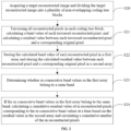
FIG. 5 is a flowchart of another embodiment of a method for data processing in a band offset mode of sample adaptive offset according to the present application; -
FIG. 6 is a detailed schematic flowchart of a step of determining whether m consecutive band values in the first array belong to the same band according to an implementation of the present application; -
FIG. 7 is a detailed schematic flowchart of a step of determining whether n consecutive band values of the m band values belong to the same band according to an implementation of the present application; -
FIG. 8 is a diagram of program means of an embodiment of an apparatus for data processing in a band offset mode of sample adaptive offset according to the present application; and -
FIG. 9 is a schematic diagram of a hardware structure of a computer device for performing a method for data processing in a band offset mode of sample adaptive offset according to an embodiment of the present application. - The advantages of the present application are further described below with reference to accompanying drawings and specific embodiments.
- Exemplary embodiments are illustrated in detail herein, and examples thereof are shown in the accompanying drawings. When the following description refers to the figures, the same numerals in different figures represent the same or similar elements unless otherwise indicated. The implementations described in the following exemplary embodiments do not represent all implementations consistent with the present disclosure. Instead, they are merely examples of apparatuses and methods consistent with some aspects of the present disclosure as detailed in the appended claims.
- The terms used in the present disclosure are merely for the purpose of describing specific embodiments, and are not intended to limit the present disclosure. The terms "a/an", "said", and "the" in the singular form used in the present disclosure and the appended claims are also intended to include the plural form unless otherwise clearly indicated in the context. It should also be understood that the term "and/or" used herein refers to and includes any or all possible combinations of one or more of the associated listed items.
- It should be understood that although the terms, such as first, second, and third, may be used in the present disclosure to describe various types of information, such information should not be limited to these terms. These terms are merely used to distinguish the same type of information from one another. For example, first information may alternatively be referred to as second information, and similarly, second information may alternatively be referred to as first information. Depending on the context, the word "if" as used herein may be interpreted as "when" or "upon" or "in response to determining".
- In the description of the present application, it should be understood that, the reference numerals of steps do not indicate the order of execution of the steps, but are merely to facilitate the description of the present application and differentiation between the steps, and thus will not be interpreted as limiting the present application.
-
FIG. 1 a schematic block diagram of a method for data processing in a band offset mode of sample adaptive offset according to an embodiment of the present application. In an exemplary embodiment, a system of the application environment may include acomputer device 10 and aserver 20. A wireless or wired connection is formed between thecomputer device 10 and theserver 20. Thecomputer device 10 may be a mobile phone, an iPad, a tablet computer, a server, or the like. Thesever 20 may be a rack server, a blade server, a tower server, or a cabinet server (including an independent server or a server cluster that includes a plurality of servers). -
FIG. 2 is a schematic flowchart of a method for data processing in a band offset mode of sample adaptive offset according to an embodiment of the present application. It may be understood that the flowchart in this method embodiment is not intended to limit an execution sequence of the steps. The following gives exemplary description by using a computer device as an execution body. It can be learned from the figure that the method for data processing in a band offset mode of sample adaptive offset in this embodiment includes the following steps. - In step S20, a target reconstructed image is acquired, and the target reconstructed image is divided into a plurality of non-overlapping coding tree blocks.
- Specifically, the target reconstructed image is an image obtained after a reconstructed image is deblocked, and is a frame of reconstructed image.
- In this embodiment, when the target reconstructed image is divided into coding tree blocks, the entire frame of image is divided into blocks based on a coding tree unit (CTU) size preset by an encoder. For example, a size of the target reconstructed image is 128×128, and the CTU size is 64×64. In this case, the target reconstructed image may be divided into four non-overlapping coding tree blocks.
- In step S21, all reconstructed pixels in each coding tree block are traversed, a band value of each traversed reconstructed pixel is calculated, and a residual value between each traversed reconstructed pixel and a corresponding original pixel is calculated.
- Specifically, a coding tree block (CTB) may be a brightness CTB or a chroma CTB included in a coding tree unit (CTU) in a sample adaptive offset (SAO) technology in HEVC. A coding tree block includes a plurality of reconstructed pixels, for example, includes 16×16, 32×32, and 64×64 pixels. In an example,
FIG. 3 shows an area including 16×16 reconstructed pixels in a coding tree block, and pixel values of the reconstructed pixels in this area are shown in the figure. - It should be noted that, for the coding tree block shown in
FIG. 3 , an 8-bit image is used as an example. A reconstructed pixel is a pixel obtained after each pixel in an original image is restored. - In this embodiment, when a band value of each reconstructed pixel is calculated, a range of pixel values included in each band may be first determined based on a pixel value range of pixels in the image. For example, if the pixel value range of the pixels in the image is 0-255, it may be determined that each band includes 256/32=8 pixel values; or if the pixel value range of the pixels in the image is 0-65535, it may be determined that each band includes 2048 pixel values.
- In an example, after a band value of each reconstructed pixel in
FIG. 3 is calculated, a band value, shown inFIG. 4 , that corresponds to each reconstructed pixel may be obtained. - A residual difference diff between each reconstructed pixel and a corresponding original pixel is a difference between a pixel value a of the reconstructed pixel and a pixel value b of the corresponding original pixel, that is, diff=a-b.
- It may be understood that, in this embodiment of the present application, to reduce a data processing time, band values and residual values of all reconstructed pixels in the coding tree block may be calculated in advance, instead of calculating the band values and the residual values when the values need to be used.
- In step S22, the calculated band value of each reconstructed pixel is stored in a first array, and the calculated residual value between each reconstructed pixel and a corresponding original pixel is stored in a second array.
- Specifically, to facilitate subsequent sequential acquisition of the band value of each reconstructed pixel and the residual value between each reconstructed pixel and a corresponding original pixel, the band value may be stored in the first array, and the residual value may be stored in the second array. For example, the band value is stored in a bttype array, and the residual value is stored in a btdiff array.
- In step S23, whether m consecutive band values in the first array belong to a same band is determined, where m is an integer greater than or equal to 2.
- In an example, whether a first batch of eight consecutive band values in the first array belong to the same band is determined. If the eight band values belong to the same band, a next batch of eight consecutive band values may be further acquired from the first array, and whether the next batch of eight consecutive band values belong to the same band is determined, until determining is performed on all band values in the first array.
- In step S24, if the m consecutive band values in the first array belong to the same band, a cumulative residual value of m reconstructed pixels corresponding to the m consecutive band values is calculated at a time based on the residual value in the second array, and a cumulative number of the m reconstructed pixels is calculated.
- Specifically, the cumulative residual value is a cumulative sum of residual values between the m reconstructed pixels and corresponding original pixels. For example, m=8, and residual values between the eight reconstructed pixels and corresponding original pixels are 5, 8, 7, 6, 4, 3, 12, 9. In this case, the cumulative residual value=5+8+7+6+4+3+12+9=54.
- The cumulative number is the number of the m reconstructed pixels. For example, if m=8, the cumulative number is also 8; or if m=4, the cumulative number is 4.
- In this embodiment, when it is determined that the m consecutive band values in the first array belong to the same band, residual values of the m reconstructed pixels corresponding to the m band values may be read from the second array at a time, and then a cumulative sum of the m read residual values may be calculated at a time, without a need to read the m residual values from the second array one by one or accumulating the read residual values one by one.
- It should be noted that, after the cumulative residual value is calculated and the cumulative number is calculated, the obtained cumulative residual value may be added to a sum variable of a corresponding band p, the cumulative number m may be added to a count variable of the corresponding band p, and then a subsequent processing operation is performed. In this embodiment, the subsequent processing operation belongs to the prior art, and details are not described in this embodiment.
- In this embodiment of the present application, all reconstructed pixels in a coding tree block are traversed, a band value of each traversed reconstructed pixel is calculated, and a residual value between each traversed reconstructed pixel and a corresponding original pixel is calculated; the calculated band value of each reconstructed pixel is stored in a first array, and the calculated residual value between each reconstructed pixel and the corresponding original pixel is stored in a second array; whether m consecutive band values in the first array belong to the same band is determined, where m is an integer greater than or equal to 2; and if the m consecutive band values in the first array belong to the same band, a cumulative residual value of m reconstructed pixels corresponding to the m band values is calculated at a time based on a residual value in the second array, and a cumulative number of the m reconstructed pixels is calculated. In the embodiments of the present application, when it is determined, through traversal, that a plurality of pixels belong to the same band, the calculation of the residuals of these pixels belonging to the same band and the calculation of the number of these pixels are completed at a time, thereby reducing memory read and write operations, and further reducing the calculation time consumption and reducing power consumption.
- Through experimental statistics, memory read and write operations of a BO means can be reduced by approximately 67.2% by using the calculation method in the present application. In addition, for no matter the Android/iOS of a mobile device or a PC, memory read and write operations are quite slow and power-consuming. Therefore, because memory read and write operations are reduced in the present application, power consumption can be greatly reduced in the calculation scheme of the present application. In addition, the BO means can also be accelerated by approximately 48.2% in the calculation method. In the prior art, in a scenario such as live streaming, a processing time of a BO means accounts for approximately 10% of the entire coding/decoding time. If the technical solution of the present application is applied to the BO means, live streaming coding can be directly accelerated by approximately 4.8%. This can not only reduce power consumption, but also accelerate live streaming coding.
- In an exemplary implementation, as shown in
FIG. 5 , the method for data processing in a band offset mode of sample adaptive offset further includes the following steps. - In step S50, if the m consecutive band values in the first array do not belong to the same band, whether n consecutive band values of the m consecutive band values belong to the same band is further determined, where n < m, and n is an integer greater than or equal to 2.
- In an example, m=8, and n=4. In this case, when it is determined that the eight consecutive band values in the first array do not belong to the same band, for example, when five consecutive band values belong to a band 15, and the other three band values belong to a
band 16, whether four consecutive band values of the eight band values belong to the same band may be further determined. - It should be noted that the n consecutive band values may be n consecutive band values at any locations of the m band values, for example, may be the 1st band value to the nth band value of the m band values, the 2nd band value to the (n+1)th band value of the m band values, or the 3rd band value to the (n+2)th band value of the m band values.
- Preferably, the n consecutive band values are the 1st band value to the nth band value of the m band values, or the (m-n+1)th band value to the mth band value of the m band values. In an example, when m=8 and n=4, the four consecutive band values are the 1st band value to the 4th band value of the eight band values, or the four consecutive band values are the 5th band value to the 8th band value of the eight band values.
- In step S51, if the n consecutive band values belong to the same band, a cumulative residual value of n reconstructed pixels corresponding to the n consecutive band values is calculated at a time based on the residual value in the second array, and a cumulative number of the n reconstructed pixels is calculated.
- Specifically, when it is determined that the n consecutive band values belong to the same band, residual values of the n reconstructed pixels corresponding to the n band values may be read from the second array at a time, and then a cumulative sum of the n read residual values may be calculated at a time, without a need to read the n residual values from the second array one by one or accumulating the read residual values one by one.
- It should be noted that, after the cumulative residual value and the cumulative number are calculated, the obtained cumulative residual value may be added to a sum variable of a corresponding band p, the cumulative number n may be added to a count variable of the corresponding band p, and then a subsequent processing operation is performed. In this embodiment, the subsequent processing operation belongs to the prior art, and details are not described in this embodiment.
- In this embodiment, when it is determined that the m consecutive band values do not belong to the same band, whether the n consecutive band values of the m band values belong to the same band is further determined, and when the n consecutive band values belong to the same band, the calculation of the residuals of these pixels belonging to the same band and the calculation of the number of these pixels are completed at a time, thereby reducing memory read and write operations, and further reducing the calculation time consumption and reducing power consumption.
- It should be noted that, in this embodiment, when it is determined that the n consecutive band values do not belong to the same band, whether k consecutive band values belong to the same band may be further determined, where k is an integer less than n. In this embodiment, a specific number of times of performing the above determining step is not limited in this embodiment, and may be set based on an actual situation.
- In an exemplary implementation, as shown in
FIG. 6 , the step of determining whether m consecutive band values in the first array belong to the same band may include steps S60 to S63. - In step S60, the m consecutive band values are read from the first array, and the read band values are stored in a first variable with preset bits.
- Specifically, the first variable may be a global variable or a local variable. In this embodiment, the first variable is preferably a local variable, for example, a local variable classIdx_64. The number of preset bits is a preset value. For example, the preset bits are 64 bits. It may be understood that the number of preset bits may alternatively be another value, and a specific value of the preset bits may be set based on an actual situation.
- In an example, the read band values may be stored in a 64-bit local variable classIdx_64.
- In step S61, one of the band values is fetched from the first variable, and the fetched band value is copied m-1 times to obtain the copied band values.
- Specifically, one band value may be randomly fetched from m band values included in the first variable, for example, the 2nd band value is fetched. Alternatively, a band value at a preset location may be fetched from the m band values included in the first variable, where the preset location is preset or defaulted. For example, if the preset location is the 1st location, a band value in the 1st location may be fetched.
- In this embodiment, after a band value is fetched, to make the number of finally obtained band values be the same as the number of band values included in the first variable, the fetched band value may be copied m-1 times to obtain copied band values, and the copied band values are stored in a second variable with the preset bits to obtain m band values.
- In step S62, the copied band values are stored in a second variable with the preset bits.
- Specifically, the second variable is of the same type as the first variable, and may be a global variable or a local variable. In this embodiment, the second variable is preferably a local variable, for example, a local variable classIdx_rep. The number of preset bits is a preset value. For example, the preset bits are 64 bits.
- In an example, the copied band values may be stored in a 64-bit local variable classIdx_rep.
- In step S63, whether the first variable is equal to the second variable is determined, and whether the m consecutive band values in the first array belong to the same band is determined based on a determination result.
- Specifically, when the determining result is that the first variable is equal to the second variable, it may be determined that the m consecutive band values in the first array belong to the same band; or when the determining result is that the first variable is not equal to the second variable, it may be determined that the m consecutive band values in the first array do not belong to the same band.
- In this embodiment, the second variable is generated by copying the fetched band value m-1 times, thereby reducing a time for generating the second variable.
- In an exemplary implementation, as shown in
FIG. 7 , when the first variable is not equal to the second variable, the determining whether n consecutive band values of the m band values belong to the same band may include steps S70 and S71. - In step S70, values in a preset number of bits that correspond to the n consecutive band values are acquired from each of the first variable and the second variable.
- Specifically, the preset number of bits may be determined based on the number of bits used to represent each band value. For example, when a band value is represented by an 8-bit value, it may be determined that the preset number of bits is 8n; when a band value is represented by a 5-bit value, it may be determined that the preset number of bits is 5n; or when a band value is represented by a 16-bit value, it may be determined that the preset number of bits is 16n.
- In this embodiment, a specific number of bits of a value to be acquired is related to locations of the n band values in the m band values.
- In an example, m=8, n=4, each band value is represented by an 8-bit value, the first variable with the preset bits is a 64-bit first variable, the four band values are the 1st band value to the 4th band value of the eight band values. In this case, when the values in the preset number of bits that correspond to the n consecutive band values are acquired from the first variable and the second variable, values from the 1st bit to the 32nd bit may be acquired from each of the first variable and the second variable.
- It may be understood that when the four band values are the 2nd band value to the 5th band value of the eight band values, when the value that has the preset number of bits and that corresponds to the n band values is acquired from the first variable and the second variable, a value with the 9th bit to the 40th bit may be obtained from each of the first variable and the second variable.
- In an exemplary implementation, if m=8, n=4, each band value is represented by an 8-bit value, and the first variable with the preset bits is a 64-bit first variable, the acquiring, from each of the first variable and the second variable, a value that has a preset number of bits and that corresponds to the n band values may include:
acquiring, from each of the first variable and the second variable, values in 32 least significant bits or 32 most significant bits. - In this embodiment, to facilitate acquisition of values from the first variable and the second variable, the value with the 32 least significant bits or the 32 most significant bits may be directly acquired.
- In step S71, whether a value acquired from the first variable is equal to a value acquired from the second variable is determined, and whether the n consecutive band values of the m consecutive band values belong to the same band is determined based on a determination result.
- Specifically, when the determining result is that the value acquired from the first variable is equal to the value acquired from the second variable, it may be determined that the n consecutive band values of the m band values belong to the same band; or when the determining result is that the value acquired from the first variable is not equal to the value acquired from the second variable, it may be determined that the n consecutive band values of the m band values do not belong to the same band.
- In an exemplary implementation, the method further includes:
if the m consecutive band values in the first array do not belong to the same band, separately calculating the residual value of each reconstructed pixel and a number of reconstructed pixels. - Specifically, when the m consecutive band values in the first array do not belong to the same band, in other words, belong to different bands, a residual value of each reconstructed pixel and the number of reconstructed pixels may be separately calculated. That is, only one residual value is read from the second array at a time. Then the read residual value is added to a sum variable of a corresponding band p, and a
number 1 is added to a count variable of the corresponding band p. Then a subsequent processing operation is performed. In this embodiment, the subsequent processing operation belongs to the prior art, and details are not described in this embodiment. -
FIG. 8 is a diagram of program means of an embodiment of an apparatus 80 for data processing in a band offset mode of sample adaptive offset according to the present application. - In this embodiment, the apparatus 80 for data processing in a band offset mode of sample adaptive offset includes a series of computer program instructions stored in a memory. When the computer program instructions are executed by a processor, the function for data processing in a band offset mode of sample adaptive offset according to each embodiment of the present application can be implemented. In some embodiments, the apparatus 80 for data processing in a band offset mode of sample adaptive offset may be divided into one or more means based on specific operations implemented by various parts of the computer program instructions. For example, in
FIG. 8 , the apparatus 80 for data processing in a band offset mode of sample adaptive offset may be divided into an acquisition means 81, a traversal means 82, a storage means 83, a determiningmeans 84, and a calculation means 85. - The acquisition means 81 is configured to acquire a target reconstructed image, and divide the target reconstructed image into a plurality of non-overlapping coding tree blocks.
- The traversal means 82 is configured to: traverse all reconstructed pixels in each coding tree block, calculate a band value of each traversed reconstructed pixel, and calculate a residual value between each traversed reconstructed pixel and a corresponding original pixel.
- The storage means 83 is configured to store the calculated band value of each reconstructed pixel in a first array, and store the calculated residual value between each reconstructed pixel and a corresponding original pixel in a second array.
- The determining means 84 is configured to determine whether m consecutive band values in the first array belong to a same band, where m is an integer greater than or equal to 2.
- The calculation means 85 is configured to: if the m consecutive band values in the first array belong to the same band, calculate, at a time based on the residual value in the second array, a cumulative residual value of m reconstructed pixels corresponding to the m consecutive band values, and calculate a cumulative number of the m reconstructed pixels.
- In an exemplary implementation, the determining
means 84 is further configured to: if the m consecutive band values in the first array do not belong to the same band, further determine whether n consecutive band values of the m consecutive band values belong to the same band, where n < m, and n is an integer greater than or equal to 2; and if the n consecutive band values belong to the same band, calculate, at a time based on the residual value in the second array, a cumulative residual value of n reconstructed pixels corresponding to the n consecutive band values, and calculate a cumulative number of the n reconstructed pixels. - In an exemplary implementation, the determining
means 84 is further configured to: read the m consecutive band values from the first array, and store the read band values in a first variable with preset bits; fetch one of the band values from the first variable, and copy the fetched band value m-1 times to obtain the copied band values; store the copied band values in a second variable with the preset bits; and determine whether the first variable is equal to the second variable, and determine, based on a determination result, whether the m consecutive band values in the first array belong to the same band. - In an exemplary implementation, when the first variable is not equal to the second variable, the determining
means 84 is further configured to: acquire, from each of the first variable and the second variable, values in a preset number of bits that correspond to the n consecutive band values; and determine whether the value acquired from the first variable is equal to the value acquired from the second variable, and determine, based on a determination result, whether the n consecutive band values of the m consecutive band values belong to the same band. - In an exemplary implementation, the determining
means 84 is further configured to fetch a band value at a preset location from the first variable. - In an exemplary implementation, m=8, n=4, each band value is represented by an 8-bit value, the first variable with the preset bits is a 64-bit first variable, and the determining
means 83 is further configured to acquire, from each of the first variable and the second variable, values in 32 least significant bits or 32 most significant bits. - In an exemplary implementation, the apparatus 80 for data processing in a band offset mode of sample adaptive offset further includes a calculation means.
- The counting means is configured to: if the m consecutive band values in the first array do not belong to the same band, separately calculate the residual value of each reconstructed pixel and a number of reconstructed pixels.
- In the embodiments of the present application, a target reconstructed image is acquired, and the target reconstructed image is divided into a plurality of non-overlapping coding tree blocks; all reconstructed pixels in each coding tree block are traversed, a band value of each traversed reconstructed pixel is calculated, and a residual value between each traversed reconstructed pixel and a corresponding original pixel is calculated; the calculated band value of each reconstructed pixel is stored in a first array, and the calculated residual value between each reconstructed pixel and the corresponding original pixel is stored in a second array; whether m consecutive band values in the first array belong to the same band is determined, where m is an integer greater than or equal to 2; and if the m consecutive band values in the first array belong to the same band, a cumulative residual value of m reconstructed pixels corresponding to the m band values is calculated at a time based on a residual value in the second array, and a cumulative number of the m reconstructed pixels is calculated. In the embodiments of the present application, when it is determined, through traversal, that a plurality of pixels belong to the same band, the calculation of the residuals of these pixels belonging to the same band and the calculation of the number of these pixels are completed at a time, thereby reducing memory read and write operations, and further reducing the calculation time consumption and reducing power consumption.
-
FIG. 9 is a schematic diagram of a hardware structure of acomputer device 10 suitable for performing a method for data processing in a band offset mode of sample adaptive offset according to an embodiment of the present application. In this embodiment, thecomputer device 10 is a device that can automatically perform numerical calculation and/or information processing according to preset or prestored instructions. For example, the computer device may be a tablet computer, a notebook computer, a desktop computer, a rack server, a blade server, a tower server, or a cabinet server (including an independent server or a server cluster that includes a plurality of servers). As shown inFIG. 9 , thecomputer device 10 at least includes, but is not limited to: amemory 120, aprocessor 121, and a network interface 123 that may be communicatively linked to each other by using a system bus. - The
memory 120 includes at least one type of computer-readable storage medium. The readable storage medium may be volatile or non-volatile. Specifically, the readable storage medium includes a flash memory, a hard disk, a multimedia card, a card-type memory (for example, an SD or DX memory), a random access memory (RAM), a static random access memory (SRAM), a read-only memory (ROM), an electrically erasable programmable read-only memory (EEPROM), a programmable read-only memory (PROM), a magnetic memory, a magnetic disk, an optical disc, and the like. In some embodiments, thememory 120 may be an internal storage means of thecomputer device 10, for example, a hard disk or memory of thecomputer device 10. In some other embodiments, thememory 120 may alternatively be an external storage device of thecomputer device 10, for example, a plug-in type hard disk equipped on thecomputer device 10, a smart media card (SMC for short), a secure digital (SD for short) card, or a flash card. Certainly, thememory 120 may alternatively include both the internal storage means of thecomputer device 10 and the external storage device of the computer device. In this embodiment, thememory 120 is generally configured to store an operating system and various application software installed on thecomputer device 10, such as program code for a method for data processing in a band offset mode of sample adaptive offset. In addition, thememory 120 may be further configured to temporarily store various types of data that have been output or are to be output. - In some embodiments, the
processor 121 may be a central processing unit (CPU for short), a controller, a microcontroller, a microprocessor, or other chips for data processing in a band offset mode of sample adaptive offset. Theprocessor 121 is generally configured to control overall operations of thecomputer device 10, for example, perform control, processing, and the like related to data exchange or communication with thecomputer device 10. In this embodiment, theprocessor 121 is configured to run program code stored in thememory 120 or to process data. - The network interface 123 may include a wireless network interface or a wired network interface. The network interface 123 is generally configured to establish a communication link between the
computer device 10 and other computer devices. For example, the network interface 123 is configured to connect thecomputer device 10 to an external terminal by using a network, and establish a data transmission channel, a communication link, and the like between thecomputer device 10 and the external terminal. The network may be a wireless or wired network, such as Intranet, Internet, the Global System for Mobile Communications (GSM for short), wideband code division multiple access (WCDMA for short), a 4G network, a 5G network, Bluetooth, or Wi-Fi. - It should be noted that
FIG. 9 shows only a computerdevice having components 120 to 122, but it should be understood that not all of the illustrated components are required to be implemented, and more or fewer components may be implemented instead. - In this embodiment, the method for data processing in a band offset mode of sample adaptive offset stored in the
memory 120 may alternatively be divided into one or more program means and executed by one or more processors (by theprocessor 121 in this embodiment) to implement the present application. - An embodiment of the present application provides a computer-readable storage medium having a computer program stored thereon, where when the computer program is executed by a processor, the steps of the method for data processing in a band offset mode of sample adaptive offset in the embodiments are implemented.
- In this embodiment, the computer-readable storage medium includes a flash memory, a hard disk, a multimedia card, a card-type memory (for example, an SD or DX memory), a random access memory (RAM), a static random access memory (SRAM), a read-only memory (ROM), an electrically erasable programmable read-only memory (EEPROM), a programmable read-only memory (PROM), a magnetic memory, a magnetic disk, an optical disc, and the like. In some embodiments, the computer-readable storage medium may be an internal storage unit of the computer device, for example, a hard disk or memory of the computer device. In some other embodiments, the computer-readable storage medium may alternatively be an external storage device of the computer device, for example, a plug-in type hard disk equipped on the computer device, a smart media card (SMC for short), a secure digital (SD for short) card, or a flash card. Certainly, the computer-readable storage medium may alternatively include both the internal storage unit of the computer device and the external storage device of the computer device. In this embodiment, the computer-readable storage medium is generally configured to store an operating system and various application software installed on the computer device, such as program code for a method for data processing in a band offset mode of sample adaptive offset in the embodiments. In addition, the computer-readable storage medium may be configured to temporarily store various types of data that have been output or are to be output.
- The apparatus embodiments described above are merely exemplary, where units illustrated as separate components may be or may not be physically separated, and the components illustrated as units may be or may not be physical units. That is, the components may be positioned at one place or distributed on at least two network units. The object of the solutions in the embodiments of the present application can be achieved by selecting some or all of the means therein according to actual needs. Those of ordinary skill in the art can understand and implement the solutions without any creative effort.
- Through the descriptions of the above implementations, those of ordinary skill in the art can clearly understand that the implementations can be implemented by software and general hardware platforms. Definitely, the implementations can also be implemented by hardware. Those of ordinary skill in the art can understand that all or some of the procedures in the methods of the above embodiments can be implemented by a computer program to instruct related hardware. The program can be stored in a computer-readable storage medium. The program, when executed, may include the procedures in the above method embodiments. The storage medium may be a magnetic disk, an optical disc, a read-only memory (ROM), or a random access memory (RAM).
Claims (11)
- A computer-implemented method for data processing in a band offset mode of sample adaptive offset, comprising:acquiring (S20) a target reconstructed image, and dividing the target reconstructed image into a plurality of non-overlapping coding tree blocks;traversing (S21) all reconstructed pixels in each coding tree block, calculating, in a sequence, a band value of each traversed reconstructed pixel, and calculating, in the sequence, a residual value between each traversed reconstructed pixel and a corresponding original pixel;storing (S22), in the sequence, the calculated band value of each reconstructed pixel in a first array, and storing, in the sequence, the calculated residual value between each reconstructed pixel and the corresponding original pixel in a second array;determining (S23) whether m consecutive band values in the first array belong to a same band, wherein m is an integer greater than or equal to 2;in response to determining that the m consecutive band values in the first array belong to the same band, calculating (S24), at once based on the residual values in the second array of m reconstructed pixels corresponding to the m consecutive band values, a first cumulative residual value of the m reconstructed pixels corresponding to the m consecutive band values, and calculating a first cumulative number of the m reconstructed pixels;adding the first cumulative residual value to a sum variable of said same band, and adding the first cumulative number to a count variable of said same band; andperforming a pixel compensation on the target reconstructed image based on the sum variable and the count variable;characterized in that:in response to determining that the m consecutive band values in the first array do not belong to the same band, further determining whether n consecutive band values of the m consecutive band values belong to the same band, wherein n < m and n is an integer greater than or equal to 2;in response to determining that the n consecutive band values belong to the same band, calculating, at once based on the residual values in the second array of n reconstructed pixels corresponding to the n consecutive band values, a second cumulative residual value of the n reconstructed pixels, and calculating a second cumulative number of the n reconstructed pixels; andadding the second cumulative residual value to thesum variable of said same band, and adding the second cumulative number to the count variable of said same band.
- The computer-implemented method according to claim 1, wherein determining whether the m consecutive band values in the first array belong to the same band comprises:reading the m consecutive band values from the first array, and storing the read band values in a first variable with preset bits;fetching one of the band values from the first variable, and copying the fetched band value m-1 times to obtain the copied band values;storing the copied band values in a second variable with the preset bits; anddetermining whether the first variable is equal to the second variable, and determining, based on a determination result, whether the m consecutive band values in the first array belong to the same band.
- The computer-implemented method according to claim 2, wherein determining whether the n consecutive band values of the m consecutive band values belong to the same band when the first variable is not equal to the second variable comprises:acquiring, from each of the first variable and the second variable, values in a preset number of bits that correspond to the n consecutive band values; anddetermining whether the values acquired from the first variable is equal to the value acquired from the second variable, and determining, based on a determination result, whether the n consecutive band values of the m consecutive band values belong to the same band.
- The computer-implemented method according to claim 2, wherein fetching one of the band values from the first variable comprises:
fetching a band value at a preset location from the first variable. - The computer-implemented method according to claim 3, wherein m=8, n=4, wherein each band value is represented by an 8-bit value, wherein the first variable with the preset bits is a 64-bit first variable, and wherein acquiring, from each of the first variable and the second variable, values in the preset number of bits that correspond to the n consecutive band values comprises:
acquiring, from each of the first variable and the second variable, a value with 32 least significant bits or 32 most significant bits. - An apparatus (80) for data processing in a band offset mode of sample adaptive offset, comprising:an acquisition means (81) configured to acquire a target reconstructed image, and divide the target reconstructed image into a plurality of non-overlapping coding tree blocks;a traversal means (82) configured to: traverse all reconstructed pixels in each coding tree block, calculate, in a sequence, a band value of each traversed reconstructed pixel, and calculate, in the sequence, a residual value between each traversed reconstructed pixel and a corresponding original pixel;a storage means (83) configured to store, in the sequence, the calculated band value of each reconstructed pixel in a first array, and store, in the sequence, the calculated residual value between each reconstructed pixel and the corresponding original pixel in a second array;a determining means (84) configured to: determine whether m consecutive band values in the first array belong to a same band, wherein m is an integer greater than or equal to 2; anda calculation means (85) configured to: calculate, in response to determining that the m consecutive band values in the first array belong to the same band, a first cumulative residual value of m reconstructed pixels corresponding to the m consecutive band values at once based on the residual values in the second array of the m reconstructed pixels corresponding to the m consecutive band values, and calculate a first cumulative number of the m reconstructed pixels;wherein the apparatus (80) further comprises:a means configured to add the first cumulative residual value to a sum variable of said same band, and adding the first cumulative number to a count variable of said same band;a means configured to perform a pixel compensation on the target reconstructed image based on the sum variable and the count variable;characterized in that the determining means (84) is further configured to :in response to determining that the m consecutive band values in the first array do not belong to the same band, further determine whether n consecutive band values of the m consecutive band values belong to the same band, wherein n < m and n is an integer greater than or equal to 2; andin response to determining that the n consecutive band values belong to the same band, calculating, at once based on the residual values in the second array of n reconstructed pixels corresponding to the n consecutive band values, a second cumulative residual value of the n reconstructed pixels, and calculating a second cumulative number of the n reconstructed pixels; andwherein the means configured to add is further configured to add the second cumulative residual value to the sum variable of said same band, and add the second cumulative number to the count variable of said same band.
- The apparatus according to claim 6, wherein determining whether the m consecutive band values in the first array belong to the same band comprises:reading the m consecutive band values from the first array, and storing the read band values in a first variable with preset bits;fetching one of the band values from the first variable, and copying the fetched band value m-1 times to obtain the copied band values;storing the copied band values in a second variable with the preset bits; anddetermining whether the first variable is equal to the second variable, and determining, based on a determination result, whether the m consecutive band values in the first array belong to the same band.
- The apparatus according to claim 7, wherein determining whether the n consecutive band values of the m consecutive band values belong to the same band when the first variable is not equal to the second variable comprises:acquiring, from each of the first variable and the second variable, values in a preset number of bits that correspond to the n consecutive band values; anddetermining whether the values acquired from the first variable is equal to the value acquired from the second variable, and determining, based on a determination result, whether the n consecutive band values of the m consecutive band values belong to the same band.
- The apparatus according to claim 7, wherein fetching one of the band values from the first variable comprises:
fetching a band value at a preset location from the first variable. - The apparatus according to claim 8, wherein m=8, n=4, wherein each band value is represented by an 8-bit value, wherein the first variable with the preset bits is a 64-bit first variable, and wherein acquiring, from each of the first variable and the second variable, values in the preset number of bits that correspond to the n consecutive band values comprises:
acquiring, from each of the first variable and the second variable, a value with 32 least significant bits or 32 most significant bits. - A computer-readable storage medium having computer instructions stored thereon that, when executed by a processor, cause the processor to perform the method according to any one of claims 1 to 5.
Applications Claiming Priority (2)
| Application Number | Priority Date | Filing Date | Title |
|---|---|---|---|
| CN202110208657.7A CN112927311B (en) | 2021-02-24 | 2021-02-24 | Data processing method and device of sideband compensation mode of sample point adaptive compensation |
| PCT/CN2022/072880 WO2022179355A1 (en) | 2021-02-24 | 2022-01-20 | Data processing method and apparatus for sample adaptive offset sideband compensating mode |
Publications (3)
| Publication Number | Publication Date |
|---|---|
| EP4246444A1 EP4246444A1 (en) | 2023-09-20 |
| EP4246444A4 EP4246444A4 (en) | 2024-04-10 |
| EP4246444B1 true EP4246444B1 (en) | 2025-03-12 |
Family
ID=76171653
Family Applications (1)
| Application Number | Title | Priority Date | Filing Date |
|---|---|---|---|
| EP22758721.9A Active EP4246444B1 (en) | 2021-02-24 | 2022-01-20 | Data processing method and apparatus for sample adaptive offset sideband compensating mode |
Country Status (4)
| Country | Link |
|---|---|
| US (1) | US12532003B2 (en) |
| EP (1) | EP4246444B1 (en) |
| CN (1) | CN112927311B (en) |
| WO (1) | WO2022179355A1 (en) |
Families Citing this family (2)
| Publication number | Priority date | Publication date | Assignee | Title |
|---|---|---|---|---|
| CN112927311B (en) * | 2021-02-24 | 2022-06-03 | 上海哔哩哔哩科技有限公司 | Data processing method and device of sideband compensation mode of sample point adaptive compensation |
| CN113068036B (en) * | 2021-03-17 | 2022-10-28 | 上海哔哩哔哩科技有限公司 | Method, apparatus, device and medium for sample adaptive compensation |
Family Cites Families (26)
| Publication number | Priority date | Publication date | Assignee | Title |
|---|---|---|---|---|
| US9055305B2 (en) * | 2011-01-09 | 2015-06-09 | Mediatek Inc. | Apparatus and method of sample adaptive offset for video coding |
| US9525884B2 (en) * | 2010-11-02 | 2016-12-20 | Hfi Innovation Inc. | Method and apparatus of slice boundary filtering for high efficiency video coding |
| JP2013090125A (en) * | 2011-10-18 | 2013-05-13 | Gaia Holdings Corp | Server for storing electric home appliance information |
| RU2626013C1 (en) * | 2011-10-19 | 2017-07-21 | Кт Корпорейшен | Video signal decoding method |
| US9277194B2 (en) * | 2011-11-08 | 2016-03-01 | Texas Instruments Incorporated | Method and apparatus for image and video coding using hierarchical sample adaptive band offset |
| US9253482B2 (en) * | 2011-11-08 | 2016-02-02 | Texas Insturments Incorporated | Method and apparatus for sample adaptive offset without sign coding |
| US9161035B2 (en) * | 2012-01-20 | 2015-10-13 | Sony Corporation | Flexible band offset mode in sample adaptive offset in HEVC |
| US9420302B2 (en) * | 2012-01-24 | 2016-08-16 | Dolby Laboratories Licensing Corporation | Weighted multi-band cross color channel predictor |
| HRP20171212T1 (en) * | 2012-04-16 | 2017-11-17 | Hfi Innovation Inc. | PROCEDURE AND APPAREL FOR FILTERING THE LOOK THROUGH BORDER OR TILE BORDERS |
| US9031137B2 (en) * | 2012-05-03 | 2015-05-12 | Texas Instruments Incorporated | Signaling signed band offset values for sample adaptive offset (SAO) filtering in video coding |
| BR112016011075B1 (en) * | 2013-11-15 | 2023-04-04 | Mediatek Inc | BLOCK-BASED ADAPTIVE LOOP FILTERING METHOD |
| CN105993174B (en) * | 2013-12-12 | 2020-03-13 | 三星电子株式会社 | Video encoding method and apparatus and video decoding method and apparatus for signaling SAO parameters |
| KR101677242B1 (en) * | 2014-02-18 | 2016-11-17 | 한국전자통신연구원 | Apparatus and method for high sample adaptive offset filtering based on convolution method |
| EP3107298A4 (en) * | 2014-03-14 | 2017-10-11 | Samsung Electronics Co., Ltd. | Image encoding method for sample value compensation and apparatus therefor, and image decoding method for sample value compensation and apparatus therefor |
| CN105635732B (en) * | 2014-10-30 | 2018-12-14 | 联想(北京)有限公司 | The method and device that adaptive sampling point compensation is encoded, is decoded to video code flow |
| CN105141948A (en) * | 2015-09-22 | 2015-12-09 | 天津师范大学 | Improved HEVC sample point self-adaption compensation method |
| EP3386198A1 (en) * | 2017-04-07 | 2018-10-10 | Thomson Licensing | Method and device for predictive picture encoding and decoding |
| CN116248864B (en) * | 2017-07-03 | 2025-06-10 | 汉阳大学校产学协力团 | Video decoding method and apparatus using division unit including additional region |
| WO2019009590A1 (en) * | 2017-07-03 | 2019-01-10 | 김기백 | Method and device for decoding image by using partition unit including additional region |
| CN120378630A (en) * | 2017-10-10 | 2025-07-25 | 韩国电子通信研究院 | Method and apparatus for using inter prediction information |
| CN109963160A (en) * | 2017-12-26 | 2019-07-02 | 北京君正集成电路股份有限公司 | Simplification SAO optimal compensation value calculating method and device based on HEVC |
| CN108810543B (en) * | 2018-06-13 | 2020-08-28 | 北京奇艺世纪科技有限公司 | Video coding compensation method and device and electronic equipment |
| WO2020139005A1 (en) * | 2018-12-28 | 2020-07-02 | 한국전자통신연구원 | Image encoding/decoding method and device, and recording medium in which bitstream is stored |
| US11496745B2 (en) * | 2019-06-24 | 2022-11-08 | Qualcomm Incorporated | Binarization in transform skip residual coding |
| CN110689590B (en) | 2019-09-23 | 2023-04-07 | 网易(杭州)网络有限公司 | Compression coding method and device for map and mobile terminal equipment |
| CN112927311B (en) * | 2021-02-24 | 2022-06-03 | 上海哔哩哔哩科技有限公司 | Data processing method and device of sideband compensation mode of sample point adaptive compensation |
-
2021
- 2021-02-24 CN CN202110208657.7A patent/CN112927311B/en active Active
-
2022
- 2022-01-20 EP EP22758721.9A patent/EP4246444B1/en active Active
- 2022-01-20 WO PCT/CN2022/072880 patent/WO2022179355A1/en not_active Ceased
-
2023
- 2023-06-27 US US18/342,669 patent/US12532003B2/en active Active
Also Published As
| Publication number | Publication date |
|---|---|
| EP4246444A4 (en) | 2024-04-10 |
| WO2022179355A1 (en) | 2022-09-01 |
| US20230353746A1 (en) | 2023-11-02 |
| EP4246444A1 (en) | 2023-09-20 |
| US12532003B2 (en) | 2026-01-20 |
| CN112927311B (en) | 2022-06-03 |
| CN112927311A (en) | 2021-06-08 |
Similar Documents
| Publication | Publication Date | Title |
|---|---|---|
| US11902538B2 (en) | Mapping method, encoder, decoder and computer storage medium | |
| EP4246444B1 (en) | Data processing method and apparatus for sample adaptive offset sideband compensating mode | |
| AU2017317847B2 (en) | Intra-prediction video coding method and device | |
| US20210160515A1 (en) | Method and device for video predicting colour component, and computer storage medium | |
| US12003764B2 (en) | Prediction method for current block and electronic device | |
| US11638014B2 (en) | Methods for determining prediction value, encoder, and decoder | |
| KR20210066823A (en) | Directions for wide-angle intra prediction | |
| US12401792B2 (en) | Data processing in edge offset mode of sample adaptive offset | |
| KR20210058846A (en) | Harmony of intra transform coding and wide-angle intra prediction | |
| US20220046231A1 (en) | Video encoding/decoding method and device | |
| US20230328253A1 (en) | Determination of Sample Adaptive Offset Mode of Coding Tree Block | |
| CN110446050B (en) | Intra-frame prediction method, device, equipment and computer readable storage medium | |
| US9866844B2 (en) | Method, system and device for image and video coding | |
| US20250350738A1 (en) | Image processing method and system, apparatus, and storage medium | |
| AU2019417996A1 (en) | Prediction decoding method, device and computer storage medium | |
| US20230370645A1 (en) | In-loop filter with multiple regions | |
| JP5846838B2 (en) | Moving picture coding method, moving picture coding apparatus, moving picture decoding method, moving picture decoding apparatus, and programs thereof | |
| CN118012650A (en) | Data transmission method, apparatus, computer device, storage medium and program product | |
| CN117873379A (en) | Data storage method |
Legal Events
| Date | Code | Title | Description |
|---|---|---|---|
| STAA | Information on the status of an ep patent application or granted ep patent |
Free format text: STATUS: THE INTERNATIONAL PUBLICATION HAS BEEN MADE |
|
| PUAI | Public reference made under article 153(3) epc to a published international application that has entered the european phase |
Free format text: ORIGINAL CODE: 0009012 |
|
| STAA | Information on the status of an ep patent application or granted ep patent |
Free format text: STATUS: REQUEST FOR EXAMINATION WAS MADE |
|
| 17P | Request for examination filed |
Effective date: 20230613 |
|
| AK | Designated contracting states |
Kind code of ref document: A1 Designated state(s): AL AT BE BG CH CY CZ DE DK EE ES FI FR GB GR HR HU IE IS IT LI LT LU LV MC MK MT NL NO PL PT RO RS SE SI SK SM TR |
|
| A4 | Supplementary search report drawn up and despatched |
Effective date: 20240311 |
|
| RIC1 | Information provided on ipc code assigned before grant |
Ipc: H04N 19/42 20140101ALI20240304BHEP Ipc: H04N 19/176 20140101ALI20240304BHEP Ipc: H04N 19/117 20140101ALI20240304BHEP Ipc: H04N 19/82 20140101ALI20240304BHEP Ipc: H04N 19/423 20140101ALI20240304BHEP Ipc: H04N 19/182 20140101ALI20240304BHEP Ipc: G06T 9/40 20060101AFI20240304BHEP |
|
| DAV | Request for validation of the european patent (deleted) | ||
| DAX | Request for extension of the european patent (deleted) | ||
| GRAP | Despatch of communication of intention to grant a patent |
Free format text: ORIGINAL CODE: EPIDOSNIGR1 |
|
| STAA | Information on the status of an ep patent application or granted ep patent |
Free format text: STATUS: GRANT OF PATENT IS INTENDED |
|
| INTG | Intention to grant announced |
Effective date: 20241118 |
|
| GRAS | Grant fee paid |
Free format text: ORIGINAL CODE: EPIDOSNIGR3 |
|
| GRAA | (expected) grant |
Free format text: ORIGINAL CODE: 0009210 |
|
| STAA | Information on the status of an ep patent application or granted ep patent |
Free format text: STATUS: THE PATENT HAS BEEN GRANTED |
|
| AK | Designated contracting states |
Kind code of ref document: B1 Designated state(s): AL AT BE BG CH CY CZ DE DK EE ES FI FR GB GR HR HU IE IS IT LI LT LU LV MC MK MT NL NO PL PT RO RS SE SI SK SM TR |
|
| REG | Reference to a national code |
Ref country code: GB Ref legal event code: FG4D |
|
| REG | Reference to a national code |
Ref country code: CH Ref legal event code: EP |
|
| REG | Reference to a national code |
Ref country code: DE Ref legal event code: R096 Ref document number: 602022011785 Country of ref document: DE |
|
| REG | Reference to a national code |
Ref country code: IE Ref legal event code: FG4D |
|
| PG25 | Lapsed in a contracting state [announced via postgrant information from national office to epo] |
Ref country code: RS Free format text: LAPSE BECAUSE OF FAILURE TO SUBMIT A TRANSLATION OF THE DESCRIPTION OR TO PAY THE FEE WITHIN THE PRESCRIBED TIME-LIMIT Effective date: 20250612 |
|
| PG25 | Lapsed in a contracting state [announced via postgrant information from national office to epo] |
Ref country code: FI Free format text: LAPSE BECAUSE OF FAILURE TO SUBMIT A TRANSLATION OF THE DESCRIPTION OR TO PAY THE FEE WITHIN THE PRESCRIBED TIME-LIMIT Effective date: 20250312 |
|
| PG25 | Lapsed in a contracting state [announced via postgrant information from national office to epo] |
Ref country code: ES Free format text: LAPSE BECAUSE OF FAILURE TO SUBMIT A TRANSLATION OF THE DESCRIPTION OR TO PAY THE FEE WITHIN THE PRESCRIBED TIME-LIMIT Effective date: 20250312 |
|
| REG | Reference to a national code |
Ref country code: LT Ref legal event code: MG9D |
|
| PG25 | Lapsed in a contracting state [announced via postgrant information from national office to epo] |
Ref country code: NO Free format text: LAPSE BECAUSE OF FAILURE TO SUBMIT A TRANSLATION OF THE DESCRIPTION OR TO PAY THE FEE WITHIN THE PRESCRIBED TIME-LIMIT Effective date: 20250612 |
|
| PG25 | Lapsed in a contracting state [announced via postgrant information from national office to epo] |
Ref country code: HR Free format text: LAPSE BECAUSE OF FAILURE TO SUBMIT A TRANSLATION OF THE DESCRIPTION OR TO PAY THE FEE WITHIN THE PRESCRIBED TIME-LIMIT Effective date: 20250312 |
|
| REG | Reference to a national code |
Ref country code: NL Ref legal event code: MP Effective date: 20250312 |
|
| PG25 | Lapsed in a contracting state [announced via postgrant information from national office to epo] |
Ref country code: LV Free format text: LAPSE BECAUSE OF FAILURE TO SUBMIT A TRANSLATION OF THE DESCRIPTION OR TO PAY THE FEE WITHIN THE PRESCRIBED TIME-LIMIT Effective date: 20250312 |
|
| PG25 | Lapsed in a contracting state [announced via postgrant information from national office to epo] |
Ref country code: BG Free format text: LAPSE BECAUSE OF FAILURE TO SUBMIT A TRANSLATION OF THE DESCRIPTION OR TO PAY THE FEE WITHIN THE PRESCRIBED TIME-LIMIT Effective date: 20250312 Ref country code: GR Free format text: LAPSE BECAUSE OF FAILURE TO SUBMIT A TRANSLATION OF THE DESCRIPTION OR TO PAY THE FEE WITHIN THE PRESCRIBED TIME-LIMIT Effective date: 20250613 |
|
| REG | Reference to a national code |
Ref country code: AT Ref legal event code: MK05 Ref document number: 1775666 Country of ref document: AT Kind code of ref document: T Effective date: 20250312 |
|
| PG25 | Lapsed in a contracting state [announced via postgrant information from national office to epo] |
Ref country code: NL Free format text: LAPSE BECAUSE OF FAILURE TO SUBMIT A TRANSLATION OF THE DESCRIPTION OR TO PAY THE FEE WITHIN THE PRESCRIBED TIME-LIMIT Effective date: 20250312 |
|
| PG25 | Lapsed in a contracting state [announced via postgrant information from national office to epo] |
Ref country code: SE Free format text: LAPSE BECAUSE OF FAILURE TO SUBMIT A TRANSLATION OF THE DESCRIPTION OR TO PAY THE FEE WITHIN THE PRESCRIBED TIME-LIMIT Effective date: 20250312 |
|
| PG25 | Lapsed in a contracting state [announced via postgrant information from national office to epo] |
Ref country code: SM Free format text: LAPSE BECAUSE OF FAILURE TO SUBMIT A TRANSLATION OF THE DESCRIPTION OR TO PAY THE FEE WITHIN THE PRESCRIBED TIME-LIMIT Effective date: 20250312 |
|
| PG25 | Lapsed in a contracting state [announced via postgrant information from national office to epo] |
Ref country code: PT Free format text: LAPSE BECAUSE OF FAILURE TO SUBMIT A TRANSLATION OF THE DESCRIPTION OR TO PAY THE FEE WITHIN THE PRESCRIBED TIME-LIMIT Effective date: 20250714 |
|
| PG25 | Lapsed in a contracting state [announced via postgrant information from national office to epo] |
Ref country code: IT Free format text: LAPSE BECAUSE OF FAILURE TO SUBMIT A TRANSLATION OF THE DESCRIPTION OR TO PAY THE FEE WITHIN THE PRESCRIBED TIME-LIMIT Effective date: 20250312 Ref country code: PL Free format text: LAPSE BECAUSE OF FAILURE TO SUBMIT A TRANSLATION OF THE DESCRIPTION OR TO PAY THE FEE WITHIN THE PRESCRIBED TIME-LIMIT Effective date: 20250312 |
|
| PG25 | Lapsed in a contracting state [announced via postgrant information from national office to epo] |
Ref country code: AT Free format text: LAPSE BECAUSE OF FAILURE TO SUBMIT A TRANSLATION OF THE DESCRIPTION OR TO PAY THE FEE WITHIN THE PRESCRIBED TIME-LIMIT Effective date: 20250312 |
|
| PG25 | Lapsed in a contracting state [announced via postgrant information from national office to epo] |
Ref country code: CZ Free format text: LAPSE BECAUSE OF FAILURE TO SUBMIT A TRANSLATION OF THE DESCRIPTION OR TO PAY THE FEE WITHIN THE PRESCRIBED TIME-LIMIT Effective date: 20250312 Ref country code: EE Free format text: LAPSE BECAUSE OF FAILURE TO SUBMIT A TRANSLATION OF THE DESCRIPTION OR TO PAY THE FEE WITHIN THE PRESCRIBED TIME-LIMIT Effective date: 20250312 |
|
| PG25 | Lapsed in a contracting state [announced via postgrant information from national office to epo] |
Ref country code: RO Free format text: LAPSE BECAUSE OF FAILURE TO SUBMIT A TRANSLATION OF THE DESCRIPTION OR TO PAY THE FEE WITHIN THE PRESCRIBED TIME-LIMIT Effective date: 20250312 |
|
| PG25 | Lapsed in a contracting state [announced via postgrant information from national office to epo] |
Ref country code: SK Free format text: LAPSE BECAUSE OF FAILURE TO SUBMIT A TRANSLATION OF THE DESCRIPTION OR TO PAY THE FEE WITHIN THE PRESCRIBED TIME-LIMIT Effective date: 20250312 |
|
| PG25 | Lapsed in a contracting state [announced via postgrant information from national office to epo] |
Ref country code: IS Free format text: LAPSE BECAUSE OF FAILURE TO SUBMIT A TRANSLATION OF THE DESCRIPTION OR TO PAY THE FEE WITHIN THE PRESCRIBED TIME-LIMIT Effective date: 20250712 |
|
| REG | Reference to a national code |
Ref country code: DE Ref legal event code: R097 Ref document number: 602022011785 Country of ref document: DE |
|
| PG25 | Lapsed in a contracting state [announced via postgrant information from national office to epo] |
Ref country code: DK Free format text: LAPSE BECAUSE OF FAILURE TO SUBMIT A TRANSLATION OF THE DESCRIPTION OR TO PAY THE FEE WITHIN THE PRESCRIBED TIME-LIMIT Effective date: 20250312 |
|
| PLBE | No opposition filed within time limit |
Free format text: ORIGINAL CODE: 0009261 |
|
| STAA | Information on the status of an ep patent application or granted ep patent |
Free format text: STATUS: NO OPPOSITION FILED WITHIN TIME LIMIT |
|
| REG | Reference to a national code |
Ref country code: CH Ref legal event code: L10 Free format text: ST27 STATUS EVENT CODE: U-0-0-L10-L00 (AS PROVIDED BY THE NATIONAL OFFICE) Effective date: 20260121 |