EP3828860B1 - Method for outputting a message of a sensor system - Google Patents
Method for outputting a message of a sensor system Download PDFInfo
- Publication number
- EP3828860B1 EP3828860B1 EP20210182.0A EP20210182A EP3828860B1 EP 3828860 B1 EP3828860 B1 EP 3828860B1 EP 20210182 A EP20210182 A EP 20210182A EP 3828860 B1 EP3828860 B1 EP 3828860B1
- Authority
- EP
- European Patent Office
- Prior art keywords
- sensor
- message
- user
- information
- closure element
- Prior art date
- Legal status (The legal status is an assumption and is not a legal conclusion. Google has not performed a legal analysis and makes no representation as to the accuracy of the status listed.)
- Active
Links
Images


Classifications
-
- G—PHYSICS
- G07—CHECKING-DEVICES
- G07C—TIME OR ATTENDANCE REGISTERS; REGISTERING OR INDICATING THE WORKING OF MACHINES; GENERATING RANDOM NUMBERS; VOTING OR LOTTERY APPARATUS; ARRANGEMENTS, SYSTEMS OR APPARATUS FOR CHECKING NOT PROVIDED FOR ELSEWHERE
- G07C9/00—Individual registration on entry or exit
- G07C9/00174—Electronically operated locks; Circuits therefor; Nonmechanical keys therefor, e.g. passive or active electrical keys or other data carriers without mechanical keys
- G07C9/00309—Electronically operated locks; Circuits therefor; Nonmechanical keys therefor, e.g. passive or active electrical keys or other data carriers without mechanical keys operated with bidirectional data transmission between data carrier and locks
-
- G—PHYSICS
- G07—CHECKING-DEVICES
- G07C—TIME OR ATTENDANCE REGISTERS; REGISTERING OR INDICATING THE WORKING OF MACHINES; GENERATING RANDOM NUMBERS; VOTING OR LOTTERY APPARATUS; ARRANGEMENTS, SYSTEMS OR APPARATUS FOR CHECKING NOT PROVIDED FOR ELSEWHERE
- G07C9/00—Individual registration on entry or exit
- G07C9/00174—Electronically operated locks; Circuits therefor; Nonmechanical keys therefor, e.g. passive or active electrical keys or other data carriers without mechanical keys
- G07C9/00944—Details of construction or manufacture
-
- G—PHYSICS
- G08—SIGNALLING
- G08B—SIGNALLING OR CALLING SYSTEMS; ORDER TELEGRAPHS; ALARM SYSTEMS
- G08B13/00—Burglar, theft or intruder alarms
- G08B13/02—Mechanical actuation
- G08B13/08—Mechanical actuation by opening, e.g. of door, of window, of drawer, of shutter, of curtain, of blind
-
- H—ELECTRICITY
- H04—ELECTRIC COMMUNICATION TECHNIQUE
- H04W—WIRELESS COMMUNICATION NETWORKS
- H04W52/00—Power management, e.g. Transmission Power Control [TPC] or power classes
- H04W52/02—Power saving arrangements
- H04W52/0203—Power saving arrangements in the radio access network or backbone network of wireless communication networks
- H04W52/0206—Power saving arrangements in the radio access network or backbone network of wireless communication networks in access points, e.g. base stations
-
- G—PHYSICS
- G08—SIGNALLING
- G08B—SIGNALLING OR CALLING SYSTEMS; ORDER TELEGRAPHS; ALARM SYSTEMS
- G08B25/00—Alarm systems in which the location of the alarm condition is signalled to a central station, e.g. fire or police telegraphic systems
- G08B25/005—Alarm destination chosen according to a hierarchy of available destinations, e.g. if hospital does not answer send to police station
-
- Y—GENERAL TAGGING OF NEW TECHNOLOGICAL DEVELOPMENTS; GENERAL TAGGING OF CROSS-SECTIONAL TECHNOLOGIES SPANNING OVER SEVERAL SECTIONS OF THE IPC; TECHNICAL SUBJECTS COVERED BY FORMER USPC CROSS-REFERENCE ART COLLECTIONS [XRACs] AND DIGESTS
- Y02—TECHNOLOGIES OR APPLICATIONS FOR MITIGATION OR ADAPTATION AGAINST CLIMATE CHANGE
- Y02D—CLIMATE CHANGE MITIGATION TECHNOLOGIES IN INFORMATION AND COMMUNICATION TECHNOLOGIES [ICT], I.E. INFORMATION AND COMMUNICATION TECHNOLOGIES AIMING AT THE REDUCTION OF THEIR OWN ENERGY USE
- Y02D30/00—Reducing energy consumption in communication networks
- Y02D30/70—Reducing energy consumption in communication networks in wireless communication networks
Definitions
- the invention relates to a method for outputting a message from a sensor system and a sensor system for a closure element for carrying out the method.
- the sensor system comprises a sensor device.
- the closure element is in particular a door or a window.
- a previously known sensor device shows WO 2016/149723 A1 , referred to there as a detection device.
- the publication US2017/175419 A1 discloses a sensor system that, in the event of an unusual change in the state of a locking element, sends a message first to a user and, if the user does not acknowledge the message, to other users.
- the sensor system determines whether an unusual change in state has occurred based on historical data.
- the publication US2018/340350 A1 also discloses a sensor system that sends a message to a user when the state of a door changes.
- the object is thus achieved by a method for outputting a message from a sensor system for a closure element.
- the closure element is in particular a door or a window.
- the sensor system comprises a sensor device.
- the embodiments for the sensor system and the sensor device described below are correspondingly advantageously applied to the method according to the invention.
- the method described can also be carried out with the sensor system according to the invention and/or the sensor device according to the invention.
- a method with a sensor system according to claim 17 as well as a sensor system with which a method according to one of claims 1 to 16 can be carried out.
- the sensor device can be connected to a higher-level electronic processing unit by cable or wirelessly.
- the sensor system can comprise the sensor device and the higher-level processing unit.
- the computing power can also be provided in the sensor device, so that the higher-level processing unit is not necessary and the sensor device is consequently designed as a sensor system.
- the optional computing unit in particular a cloud, is arranged outside the sensor device.
- the computing unit can be connected to the sensor device via a local network or the Internet for communication (also referred to as data transmission or data exchange). In particular, it is intended to arrange the computing unit far away from the sensor device.
- the sensor system comprises a particularly mobile user device, e.g. a mobile phone, a tablet, a laptop, or is designed to communicate with the mobile user device.
- a particularly mobile user device e.g. a mobile phone, a tablet, a laptop, or is designed to communicate with the mobile user device.
- the sensor system can have an electronic detection unit that is arranged outside the sensor device, but in particular in its wireless communication range.
- the detection unit for example designed as a router or gateway, can represent the data-transmitting connection between the computing unit and the sensor device.
- the detection unit can represent the data-transmitting connection between the user device and the sensor device.
- the detection unit is intended to be arranged near the sensor device.
- the detection unit is designed for fixed installation in the communication range of the sensor device.
- the sensor device preferably comprises a transmitting and/or receiving unit.
- the transmitting and/or receiving unit is designed for communication, i.e. data transmission, in particular wirelessly, with the user device and/or the detection unit and/or the computing unit.
- the transmitting and/or receiving unit is preferably designed for wireless short-range communication, e.g. Bluetooth Low Energy or NFC.
- the transmitting and/or receiving unit is preferably designed only for wireless short-range communication, in particular Bluetooth Low Energy or NFC.
- the transmitting and/or receiving unit communicates in particular with the detection unit via wireless short-range communication.
- the detection unit is preferably located within the communication range of the transmitting and/or receiving unit.
- the computing unit is located outside the communication range of the transmitting and/or receiving unit.
- the transmitting and/or receiving unit arranged in the sensor device communicates with the user device via the detection unit and/or directly.
- the transmitting and/or receiving unit can communicate directly wirelessly with the user device, provided that the user device is located in the communication range of the transmitting and/or receiving unit.
- communication from the transmitting and/or receiving unit can also take place via the recording unit and the computing unit with the user device. This is particularly the case if the user device communicates with the computing unit via an external network, in particular the Internet or a telecommunications network, and/or the user device is outside the communication range of the transmitting and/or receiving unit.
- the recording unit and the computing unit can be connected via the Internet and/or a telecommunications network.
- the sensor device comprises at least one sensor.
- a sensor axis is preferably defined on the sensor.
- the sensor in turn preferably comprises at least one coil.
- the coil is described in places below; however, it should always be understood that preferably several coaxial coils are used. Different impedances and/or different induced voltages are preferably detected with the at least one coil.
- the senor is designed as a light barrier, for example, whereby changes in brightness are detected in particular at the receiver of the light barrier.
- the senor is designed as a Hall sensor or as a reed switch.
- the senor can be designed as a switch, in particular as a microswitch, or as a contact foil.
- the senor is designed as an acceleration sensor.
- the coil in particular has at least one winding that extends around a coil axis; the coil axis corresponds to the sensor axis.
- the coil is used in particular to be penetrated by a locking element.
- the coil is therefore designed to be penetrated by a locking element.
- the sensor particularly preferably has a through-hole around the sensor axis.
- the through-hole is designed to be penetrated by the locking element.
- the locking element preferably moves parallel to the sensor axis.
- the preferably used coil extends around the through-hole.
- the sensor device preferably comprises an electrical system.
- the electrical system is designed in particular to supply power to and/or control the sensor, in particular the coil(s).
- the electrical system is preferably at least partially electrically connected to the sensor, in particular the coil(s).
- control of the sensor or the coil is to be understood as meaning that the electrical system applies a specific signal to the sensor, in particular the coil, and/or is designed to detect a signal generated in the sensor, in particular a signal induced in the coil.
- the electrical system preferably comprises electronics.
- the electronics in particular comprise the transmitting and/or receiving unit.
- the electronics preferably comprise an electronic control unit, in particular a processor or controller.
- the control unit comprises in particular a non-volatile memory.
- the electronics are composed of several electronic components.
- the electronics are designed in particular to control the sensor.
- At least one coil is controlled.
- a signal is applied to the coil(s) and/or a signal is taken from the coil(s).
- the locking element for example designed as a door or window, has a door leaf or window leaf.
- This door leaf or window leaf can be "open” or “closed”.
- the locking element preferably has a locking element.
- This locking element is, for example, a bolt or a latch of a mortise lock in the door leaf.
- the locking element has the state “bolt extended” or “bolt retracted”. In the "bolt extended” state, the locking element protrudes further from the locking element leaf than in the "bolt retracted” state.
- operating states of the locking element namely "open” or "closed” and/or "bolt extended” or “bolt retracted”.
- both the state of the door or window leaf and the locking element are combined into one operating state. This results in four basic operating states of the locking element: open-bolt extended state, open-bolt retracted state, closed-bolt extended state and closed-bolt retracted state.
- a locking element gap is formed between the door leaf or window leaf, generally referred to as the locking element leaf, and a surrounding locking element frame.
- a mortise lock is arranged in the door leaf.
- the mortise lock closes with the faceplate in the direction of the locking element gap.
- the strike plate mounted in the locking element frame or as an integral part of the locking element frame.
- a locking element can extend from the faceplate. This locking element extends, for example, through the locking element gap along the sensor axis into a corresponding opening in the strike plate.
- This locking element is, in particular, a bolt or a latch.
- windows there are corresponding elements that can extend through the locking element gap into a corresponding opening in the locking element frame.
- the sensor device presented here is preferably designed to be arranged in this closure element gap.
- the sensor device is located on a side of a first closure element part facing the closure element gap, in particular the closure element leaf (in particular the cuff) or the frame (in particular the strike plate).
- the opposite part without a sensor device is referred to as the "second closure element part”.
- the sensor device is arranged in such a way that the sensor axis is aligned with the locking element and the associated opening.
- the sensor device is particularly preferably arranged on the closure element leaf side (in particular on the door leaf side or window leaf side).
- the sensor system is designed to detect different operating states of the locking element.
- the sensor system can detect whether the door leaf or window leaf is "open” or “closed”. Additionally or alternatively, the sensor system can detect whether the locking element is retracted or extended. In particular, the sensor system can detect the operating states of the locking element: open-lock-extended state, open-lock-retracted state, closed-lock-extended state and closed-lock-retracted state. This makes it possible to send appropriate information about the operating state and/or a manipulation attempt resulting from the operating state and/or other circumstances.
- the invention provides that in a method for outputting a message from the sensor system for a closure element, the message is only output if both a predetermined operating state and further "additional information" are present.
- the operating state that is detected by the sensor system, in particular the sensor device, is therefore combined with the additional information. If both values correspond to a specification, the message is output.
- the operating state determined corresponds to a first specification and the additional information corresponds to a second specification so that the message is output.
- the method is carried out in particular in the sensor system described here.
- the method according to the invention comprises the following steps: determining a current operating state of the closure element using at least one sensor of a sensor device of the sensor system.
- the entire sensor system and in particular the at least four operating states have already been explained in detail above.
- Additional information is then recorded.
- This additional information is independent of the sensor device and/or the closure element.
- this additional information relates to information about a user, i.e. a person, or for example other information from the building in which the closure element is installed.
- a message is output if at least the determined operating state corresponds to a specification and in particular at the same time the recorded additional information corresponds to a specification.
- capturing the additional information simply means gaining knowledge about this additional information.
- This additional information reaches the sensor system in particular via a local network or the Internet.
- This information can reach the sensor system via the computing unit, the recording unit or the user device. It is also possible to transfer the information directly to the sensor device.
- the necessary computing power can in turn be provided outside the sensor device, in particular in the higher-level computing unit. However, as described many times before, it is also possible to provide the computing power in the sensor device itself.
- the message can be sent by the sensor device itself, i.e. by the transmitting and/or receiving unit.
- the message can be sent directly to the recipient or indirectly via the computing unit and/or According to the invention, the message is sent to a user device.
- the message is displayed on the user device.
- a change in the operating state of the locking element is detected and, as a further prerequisite for the output of the message, a change in the operating state of the locking element has occurred. This prevents the user from being overwhelmed by information.
- a command from a user in particular from a mobile user device of the user, can be received wirelessly via the transmitting and/or receiving unit.
- the sensor device is preferably designed to activate the sensor in response to such a command and to determine at least one operating state of the closure element by means of the sensor.
- the operating state determined in this way is also output as a message if there is no change in the operating state.
- the operating state is not recorded regularly, at least temporarily, but when there is a change in the operating state.
- the sensor device can comprise a detection device for detecting a change in the operating state. The fact that there is a change in the operating state can be detected by the detection device, for example an acceleration sensor or Hall sensor, on the closure element. If such a change in the operating state occurs, the new operating state can be determined using the sensor. This is followed by a comparison with the specification, in particular with the first specification, and, in particular at the same time, a comparison of the additional information with the specification, in particular with the second specification. If both values correspond to the specification or specifications, the message is sent.
- the operating state can be sent to the higher-level processing unit.
- the processing unit can then compare the operating state with the specification.
- the processing unit can also compare the additional information with the specification value. This is preferably done without the processing unit sending the additional information to the sensor device.
- the computing unit then decides independently whether to send the message.
- the computing unit records the additional information without communicating with the sensor device. Rather, the computing unit records the additional information, for example, using the user device and/or information from the Internet and/or information stored in the computing unit.
- the sensor device has no knowledge of the additional information. Thus, the computing unit, but not the sensor device, has the information to decide whether to send the message. So that the computing unit is aware of the operating state of the closure element, the sensor device sends the operating state to the computing unit.
- WO 2016/149723 A1 describes a sensor and its use.
- the sensor used according to the present invention can be designed in the same or similar manner. Accordingly, in particular the control of the coil(s) can be WO 2016/149723 A1 can also be used for the present invention.
- WO 2016/149723 A1 As already mentioned in WO 2016/149723 A1 described, it was found that electrical measured values at the at least one coil are influenced by both the state of the locking element (in WO 2016/149723 A1 referred to as locking element) and to a small extent by the door state.
- the state of the locking element and also the door state can be determined solely by the electrical measurement using the sensor, without additional buttons or changes to the locking element being necessary.
- the coil axis is arranged in such a way that the locking element can penetrate at least one coil, it is possible to use the coil to detect whether the locking element extends through the coil or not.
- the locking element is of course at least partially made of metal.
- the impedance changes when the door is closed compared to when the door is open due to the proximity of the partially metal second locking element part.
- the sensor can detect whether the at least partially metal door frame, in particular the metal strike plate, is located near the coil and thus the door is closed or not.
- the coil can detect whether the at least partially metal door leaf, in particular the metal faceplate or the metal lock, is located near the coil and thus the door is closed or not.
- the coil(s) are to be as low as possible in height, it is advisable to install the electronics (measuring device in WO 2016/149723 A1 ) in such a way that it is suitable for measuring the impedance of the coil while it is being supplied with an alternating voltage signal or an alternating current signal.
- the sensor can be equipped with just one coil, which results in the sensor device being as thin as possible.
- the impedance of the coil changes when the locking element is extended or retracted and to a small extent when the partially metal second locking element part (by closing the door) comes into the area of the coil.
- the impedance of the coil can be compared with predetermined values.
- the reliability of determining the status of the locking element and the door leaf can be significantly increased by applying signals of different frequencies to the coil one after the other using the electrical system.
- the impedance is then determined at these different frequencies and compared with predetermined values. If, for example, measurements are taken at three frequencies and the status of the locking element and possibly the status of the door is determined from each measurement, a majority decision can be made if the results are different. On the other hand, it is often possible that two states at a certain frequency produce very similar measured values and can therefore hardly be distinguished, so that for this reason alone a measurement at different frequencies is indicated.
- the power consumption increases compared to a single measurement. It may be useful to equip the sensor with at least two coils.
- the at least two coils are coaxial to each other. This involves a transmitting coil and a receiving coil.
- the transmitting coil is supplied with alternating current.
- the induced voltage is recorded in the receiving coil.
- the induced voltage in the receiving coil changes more significantly than the impedance, especially when the door state changes. In this way, measurements at different frequencies can be avoided, which can minimize power consumption.
- the reliability can be increased even further if an additional receiving coil is provided, so that a receiving coil is arranged on both sides of at least one transmitting coil.
- the electronics detect the difference in the voltage induced in the two receiving coils while the at least one transmitting coil is supplied with alternating current.
- the sensor comprises at least three coils or four coils.
- the at least three coils are arranged one above the other.
- the coils can be arranged coaxially to one another.
- the transmitting coil(s) is/are located, in particular symmetrically, between the two receiving coils. If an iron core (the locking element) is located exactly symmetrically in this arrangement, exactly the same voltage is induced in the two receiving coils, the differential voltage between the two receiving coils is therefore 0. However, if the iron core shifts in one direction or the other, the arrangement becomes asymmetrical and an induced differential voltage results at the two receiving coils.
- the induced differential voltage changes when the door is closed compared to an open door due to the proximity of the second at least partially metal locking element part. It is possible to arrange a transmitting coil between the receiving coils. Furthermore, it is also possible to arrange at least two transmitting coils between the two receiving coils.
- the two transmitting coils are in particular part of a common circuit and/or send a common signal.
- the two receiving coils can also be part of a common circuit. Therefore, one can also speak of a transmitting coil with two winding areas and a receiving coil with two winding areas.
- the sensor can, regardless of the number of coils, detect the door states open and closed as well as the locking element states bolt retracted and Detect the bolt extended.
- the sensor device can thus use the sensor to detect the operating states of open-bolt extended, open-bolt retracted, closed-bolt extended and closed-bolt retracted.
- the electronics at least supply current to the coil and/or directly detect the impedance or induced voltage. Further evaluations, such as comparison with stored values, can also be carried out in the electronics, in particular in the control unit, or in the higher-level processing unit.
- the sensor system in particular the sensor device, can detect the operating state "sensor outside the operating position".
- the operating state In the operating state "sensor outside the operating position”, the sensor is outside the operating position, wherein the sensor device is attached to the first closure element part in the operating position.
- the operating state "sensor outside the operating position” is determined by sensor values that characterize a distance to the first, at least partially metal closure element part, wherein the distance is greater than in the operating position.
- the sensor device comprises fastening means for fastening to the first closure element part.
- the fastening means can in particular be designed as the adhesive element. If the sensor comprises at least one transmitting coil between two receiving coils, a different, in particular lower, voltage is induced in the receiving coil facing the fastening means when the distance to the first closure element part is greater than in the operating position than in the operating position. In particular, this also changes the differential voltage between the two receiving coils. This makes it possible to determine the operating state "sensor outside the operating position".
- the sensor system in particular the sensor device, can use the sensor to detect a further operating state, namely the operating state "sensor outside the operating position", in addition to the operating states open-latch extended, open-latch retracted, closed-latch extended and closed-latch retracted.
- a message is always sent when the operating state "sensor outside the operating position" is detected.
- the sensor system can comprise a sensor, in particular a first sensor, to detect whether the door leaf or the window leaf is open or closed.
- the sensor system can comprise a sensor, in particular a second sensor, to detect whether the locking element is retracted or extended.
- the sensor which is designed to detect whether the door leaf or window leaf is open or closed, can be designed as a Hall sensor or a reed switch, for example.
- a magnet is arranged on the second closure element part and the Hall sensor or the reed switch on the first closure element part.
- the sensor which is designed to detect whether the door leaf or window leaf is open or closed, can be designed as a light barrier.
- the light barrier can be designed as a reflection light barrier.
- the second closure element part can reflect the light from the light barrier when closed, while there is no reflection of the light on the second closure element part when open.
- the sensor which is designed to detect whether the door leaf or window leaf is open or closed, can be designed as a switch, in particular a microswitch.
- an actuating element protrudes into the door gap, with which the switch can be actuated.
- the actuating element can also fulfill another purpose and, for example, serve as the latch of a mortise lock.
- the sensor which is designed to detect whether the locking element is retracted or extended, can be designed as a Hall sensor or a reed switch, for example.
- a magnet is arranged on the locking element, which interacts with the Hall sensor or reed switch.
- the sensor which is designed to detect whether the locking element is retracted or extended, can be designed as a light barrier.
- the light barrier can be designed as a reflection light barrier or a transmission light barrier. The light can be reflected on the locking element in one of the locking element states, e.g. in the extended state, and in the other In one locking element state, e.g.
- the sensor that is designed to detect whether the locking element is retracted or extended can be designed as a switch, in particular as a microswitch.
- the switch can be actuated, while in the other locking element state, e.g. in the retracted state, the switch is not actuated.
- a contact foil can be used. An electrical signal is generated on the contact foil by touching the locking element.
- a signal is generated on the contact foil by the locking element, while in the other locking element state, e.g. in the retracted state, the locking element does not generate a signal on the contact foil.
- the sensor that is designed to detect whether the locking element is retracted or extended can be designed as an acceleration sensor.
- the acceleration sensor is connected to the locking element. First, you have to set the initial state of the locking element. Then, with each locking element movement, the acceleration sensor and the history can be used to determine whether the locking element is moving into the retracted or extended state.
- the first sensor and/or the second sensor may be arranged on the door or window frame.
- the first sensor and/or the second sensor may be arranged on or in the door leaf.
- the first sensor and/or the second sensor may be arranged in a mortise lock.
- both the first sensor and the second sensor are arranged together on a locking element part, i.e. the locking element frame or the locking element leaf.
- the transmitting and/or receiving unit can, particularly in these cases, communicate with the computing unit via cable.
- the transmitting and/or receiving unit may be designed as a bus interface.
- the specification in particular the first specification, can include certain operating states.
- the first specification includes that a message is to be issued when the closure element is opened and/or when the Locking element is retracted.
- the specification particularly as the first specification, can include the presence of the operating state open-lock-extended, open-lock-retracted or closed-lock-retracted. The specification does not, however, include the presence of the operating state closed-lock-retracted. This means that if the locking element is closed and the locking element is extended, no message is issued.
- the additional information is information about at least one user.
- Information from multiple users can also represent a common additional information.
- the multiple pieces of additional information are then preferably compared with a specification. If the multiple pieces of additional information correspond to the specification and, in particular, the operating state corresponds to the specification at the same time, the message is output.
- the information about the user is location information about the user, in particular about their user device.
- This is location information, e.g. based on satellite navigation data and/or GSM location of the user device.
- location information e.g. based on satellite navigation data and/or GSM location of the user device.
- it is defined as a specification, in particular as a second specification, that the user device must exceed a defined distance from the closure element and/or the sensor device.
- a message is only issued if the additional information is present that the user device exceeds the distance.
- a user who is close to the closure element and can determine the operating state by eye contact is thus relieved of an unnecessary message.
- the specification can additionally or alternatively be that the user device is outside the spatial area that the closure element closes.
- the output of the message therefore requires the user to move away from the locking element.
- the user device can be less than a defined distance from the closure element and/or the sensor device. The user must therefore be nearby in order to respond to the message.
- Location information can be extracted from a calendar entry in a user's digital calendar.
- the sensor system can have access to the digital calendar and/or the digital calendar is stored in the sensor system. Based on these calendar entries, information about where the user is located can be extracted. For example, the calendar entry "meeting in New York" would lead to the conclusion that no message should be displayed to the user via a locking element on a door in Hamburg. For example, the user may not want the message because the user cannot respond. On the other hand, it is conceivable to send a message for the calendar entry "meeting in New York". The corresponding user is therefore out of the house and would like to be notified whether the state of the locking element changes. The additional information is therefore "stay in New York” and the specification, in particular the second specification, is to output or not output the message if the user is more than a defined distance from the locking element and/or the sensor device.
- the information about the user corresponds to a time profile or time information, in particular from a digital calendar of the user.
- the user can store in the sensor system according to which time profile he would like to receive the message or not. This means that the message is only sent to the corresponding user if he wants it at the given time.
- the digital calendar e.g. Outlook ®
- the user device can forward the digital calendar to the computing unit.
- At least one time period is determined by both the time profile and the digital calendar.
- the specification, in particular the second specification can be that the current time is within the time period.
- the additional information consists of knowing the time period and also checking whether the current time is within the time period.
- the computing unit can therefore have information about the location of the user device as well as the time period of absence of the user.
- the message is sent when, for example, either the user device is away from the spatial area that the locking element closes or there is a time period of absence of the user.
- the method comprises the following steps: First, several additional information items are recorded, with at least one piece of information being recorded as additional information from at least two different users. The message is then only output if at least the determined operating state of the closure element corresponds to a specification and at the same time the at least two additional information items recorded from the at least two users each correspond to a corresponding specification.
- location information and/or time information and/or information from digital calendars in particular location and/or time information, and/or stored time profiles can be used.
- the location information and/or the information from the digital calendars and/or the time profiles about the multiple users can indicate that the multiple users are absent in a spatial area that can be closed by the closure element. It is possible that, in particular exclusively, the location information, e.g. location information from user devices of the multiple users, is used as additional information. It is possible that, in particular exclusively, time information, in particular time information from digital calendars, is used as additional information. It is also possible that a combination of location and time information is used as additional information.
- determination methods can be used, such as exceeding a distance, as previously described for a user.
- the users In particular, the user devices that are used to generate the additional information can be stored in the sensor system.
- the absence of the multiple stored users is the additional information that is required to output the message. This can be determined, for example, by exceeding the defined distance of the stored user devices from the sensor device and/or the locking element. If, on the other hand, a stored user is at home, the message is not sent. This can be determined, for example, by falling below the defined distance of the user device from the sensor device and/or the locking element.
- the presence of other, non-stored people or user devices does not prevent the message from being output.
- the user devices of multiple users e.g. family members, are stored in the sensor system. If the stored users are out of the house and there is a change in the operating state, the message is output even if a user device, e.g. the user device of a postman, is within the spatial area.
- a message is output even though at least a first of the stored user devices is at home, in particular at least a first of the stored user devices is less than the defined distance from the sensor device and/or the closure element.
- the sensor system has previously learned that the first user device is not to be used to generate the additional information.
- another stored user device can inform the sensor system.
- a user e.g. a family member, can forget their user device at home, and another user can still enable the message to be output using their stored user device by "deactivating" the forgotten user device with respect to the sensor system.
- the users whose digital calendars are to be used to determine the additional information can be stored in the sensor system.
- the sensor system receives the time information from the digital calendars of the stored users. For example, the message is only issued if there is a calendar entry in all of the stored users' digital calendars.
- the message is output on a particularly mobile user device, in particular a mobile phone.
- the specification could, for example, be that the corresponding user must be within a maximum distance, e.g. within a radius of 10 kilometers, of the locking element.
- the specification could additionally or alternatively be that the user device is closer to the sensor device than the other user devices.
- the user device that is closest to the sensor device is preferably selected from several users. This increases the probability that the user who can react to the message accordingly, for example, can close the door or use the unused room for another meeting, will receive the message.
- the user receives the corresponding message.
- Another requirement would be that the user has not excluded receipt of the message, for example through the stored time profile. This makes it possible to identify users to whom the message should be delivered and users to whom the message should not be delivered.
- the message is output on at least one further user device if the operating state of the closure element does not change within a predetermined period of time and/or the sensor system lacks a message input within the predetermined period of time which would indicate that the at least one user who received the message has acknowledged the message.
- a message is issued if the operating state is a latch retracted state and the information, in particular the location information, about the multiple users indicates that the multiple users, in particular all users about whom the sensor system should have information, are absent.
- the absence may result from a distance of the user devices from the locking element and/or the sensor device or the absence in the spatial area.
- the operating state is a bolt retracted state, in particular the bolt retracted open state or the bolt retracted closed state, and at the same time it is detected, in particular based on the location information, that all or in particular all of the stored users are absent, at least one user receives a corresponding message.
- the person who leaves the house last receives a corresponding message on the user device that he is the last one and should lock the door, i.e. extend the bolt.
- the operating state is open, regardless of the locking position, and the location information of several, in particular all, users indicates that the users are absent, a message is issued.
- the absence can be determined by a distance of the user devices from the locking element and/or the sensor device or the absence in the spatial area. In this way, at least one user can be informed that there is no longer a user in the vicinity of the open locking element.
- the additional information corresponds to information about a room. This room is closed in particular with the locking element.
- the sending of the message can also be made dependent on several additional pieces of information meeting the corresponding requirements. For example, the message can only be sent if both a Additional information about the room as well as additional information about at least one user corresponds to the corresponding specification.
- the information about the room can correspond to a business hour or business hours. This is particularly intended if the room corresponds to a business premises. It is conceivable that the business hour or business hours do not have to be explicitly entered into the sensor system as a time profile, but that the sensor system receives the information about the business hour or business hours that has already been stored elsewhere.
- the business hour can be stored on a business website, in a burglar alarm system or in a business digital calendar. It is conceivable that the sensor system can access the business hour stored in this way. It may be that a message is only issued if the second specification is that the current time is outside of business hours.
- the sensor system comprises a sensor device as used in the context of this invention with multiple optional
- the electronic device can be the electronics of the sensor device, the detection unit and/or the computing unit.
- a spatial direction is defined.
- the spatial direction is specified by a straight line that runs across the sensor axis, in particular the coil axis.
- the spatial direction extends radially outwards from the sensor axis.
- the electrics connect to the sensor along this spatial direction.
- this spatial direction intersects the electrics.
- a third imaginary axis can be defined at the intersection point of the spatial direction with the sensor axis. This third imaginary axis is perpendicular to the sensor axis and perpendicular to the spatial direction. In particular, this third imaginary axis does not intersect the electrics.
- the sensor device has a height of at most 2.5 mm, preferably at most 2.3 mm, particularly preferably at most 2.1 mm, at its highest or thickest point.
- the electrical system viewed from the direction of the sensor axis, in particular the coil axis, is arranged next to the sensor, in particular next to the coil.
- the entire electrical system viewed from the direction of the sensor axis, in particular the coil axis, is arranged next to the sensor, in particular next to the coil.
- the sensor axis, in particular the coil axis does not intersect any component of the electrical system.
- the electrical system is thus arranged completely transversely to the sensor axis, in particular the coil axis.
- the sensor device in particular comprising the sensor with coil and the electrics, is thus preferably arranged in one plane. This results in a very thin structure of the entire sensor device and it is possible to arrange the sensor device in a closure element gap.
- the transmitting and/or receiving unit is integrally connected to a front and/or back of the sensor device.
- the transmitting and/or receiving unit can be attached to or in a circuit board.
- the circuit board can in particular be an electronic circuit board part.
- the circuit board can form the front and/or back of the sensor device or be integrally connected to the front and/or back.
- the transmitting and/or receiving unit is integrally connected to the front and back. This makes it possible to achieve a low installation height and still provide the transmitting and/or receiving unit so that wireless communication can take place to send the message.
- the object of the invention is also achieved by an arrangement with a closure element and a sensor system according to the invention.
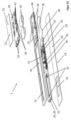
- Figure 1 shows a purely schematic representation of an arrangement 2.
- the arrangement 2 comprises a sensor device 1 and a closure element 3, here designed as a door. Only a section of the closure element 3 is shown.
- the locking element 3 comprises a lock 4 in a door leaf; generally referred to as the first locking element part 65.
- the lock 4 in turn has a faceplate 7.
- a locking element 5, designed here as a bolt In the lock 4 there is a locking element 5, designed here as a bolt.
- the locking element 5 can be extended and retracted using a key, for example.
- the locking element 5 can be moved along a coil axis 22. This coil axis 22 is part of the sensor device 1 and will be explained in more detail.
- the lock 4 can have a further locking element 6, for example in the form of a latch.
- the locking element 5 penetrates the sensor device 1.
- the sensor device 1 can also be designed and arranged such that the further locking element 6 (latch) penetrates the sensor device 1 and is detected by the sensor device 1.
- the frame, generally referred to as the second locking element part 66, of the arrangement 2 is located opposite the door leaf.
- the strike plate 8 is located in this frame as a separate component or integral area.
- the strike plate 8 has a latch opening 9 and a bolt opening 10.
- the bolt element 5 extends into this bolt opening 10 in the extended state. Accordingly, the further bolt element 6 extends into the latch opening 9.
- a locking element gap 11 is formed between the face plate 7 and the strike plate 8.
- the sensor device 1 is located in this locking element gap 11. The sensor device 1 is in the operating position.
- the sensor device 1 has a front side 12 and a back side 13.
- the front side 12 and back side 13 are defined in particular perpendicular to the coil axis 22.
- the back side 13 forms the mounting surface of the sensor device 1 and is attached, in particular glued, to a support surface on the faceplate 7.
- the sensor device 1 and thus also the support surface can extend beyond the faceplate 7.
- the front side 12 faces the closure element gap 11.
- Figure 1 further shows a sensor system 60 comprising the sensor device 1.
- the sensor system 60 also comprises a higher-level computing unit 61, a detection unit 62 and a user device 64, for example a mobile phone.
- Figure 1 also purely schematically the transmitting and/or receiving unit 63 in the sensor device 1.
- the transmitting and/or receiving unit 63 communicates, in particular wirelessly, directly with the computing unit 61 and/or via the detection unit 62 with the computing unit 61.
- the detection unit 62 is located in particular in the communication area for wireless data transmission with the sensor device 1, for example near the door.
- the detection unit 62 is preferably connected by cable to the computing unit 61 for data transmission. However, wireless transmission is also possible here.
- the user device 64 can communicate, in particular wirelessly, directly with the transmitting and/or receiving unit 63 or via the computing unit 61 or the detection unit 62 with the sensor device 1.
- the sensor device 1 is also possible to arrange the sensor device 1 on the other side, namely on the striking plate 8.
- the Figures 2 to 9 show in different representations the basic structure of the sensor device 1 as well as certain special features of the first variant of the sensor device 1.
- the sensor device 1 comprises a sensor 20.
- the sensor 20 in turn has at least one coil 21, which is shown here only purely schematically.
- the coil 21 defines the coil axis 22.
- the at least one coil 21 is formed in or on a sensor board part 24.
- the coil 21 is a conductor track in the sensor board part 24.
- the sensor board part 24 lies on a base element 23.
- the base element 23 is made of electrically non-conductive material, in particular plastic. Both the base element 23 and the coil 21 and the sensor board part 24 have a through-hole 25.
- the coil axis 22 extends through this through-hole 25.
- the sensor device 1 is arranged in the arrangement 2 in such a way that the locking element 5 can extend through this through-hole 25 along the coil axis 22.
- at least one or two transmitting coil(s) and two receiving coils are arranged one behind the other in the direction of the coil axis 22.
- the transmitting coil(s) is/are enclosed by the receiving coils.
- a receiving coil is arranged, then the transmitting coil(s) and then another receiving coil.
- the structure with three coils 21 is shown in Fig.8 shown.
- FIG 2 which is a top view of the front side 12, the receiver coil 21 shown covers the transmitting coils behind it as well as the further receiver coil facing the back.
- the voltage difference induced in the two receiver coils makes it possible to detect the proximity of metal to the second locking element part 66. This makes it possible to detect whether the locking element is open or closed. Furthermore, a change in the induced voltage in the receiver coils can be used to detect whether the locking element 5 is extended or retracted.
- the operating states of the locking element 3 namely an open-lock-extended state, an open-lock-retracted state, a closed-lock-extended state and a closed-lock-retracted state, can thus be detected by means of the sensor 20.
- the metal content of the locking element parts 65, 66 and the locking element 5 can vary, when the sensor device 1 is put into operation, the above-mentioned operating states are assigned to sensor values, in particular Amplitude changes and/or phase shifts of the voltages or voltage differences induced in the receiver coils. The sensor device is thus calibrated during commissioning.
- the sensor device 1 can detect a further operating state, namely the operating state "sensor outside the operating position". This is a state in which the sensor 20 or the entire sensor device 1 has been removed from the first closure element part 65. In this case, in particular the induced voltage that is induced in the receiver coil facing the first closure element part 65 changes.
- the sensor device has a height in the direction of the coil axis 22 of at most 2.5 mm, preferably at most 2.3 mm, particularly preferably at most 2.1 mm.
- the sensor device 1 Because the sensor device 1 is attached to the locking element sheet 65, the sensor device 1 requires an independent power supply in the form of energy storage devices 45. For better retrofitting, a wired connection to an external power supply is not provided.
- the invention provides that the sensor device determines the operating state of the locking element. In this case, the open bolt extended state, the open bolt retracted state, the closed bolt extended state, the closed bolt retracted state and the sensor outside the operating position state can be determined.
- the computing unit 61 has additional information. If the operating state corresponds to a first specification and the additional information corresponds to a second specification, a message is output. The checking of whether the additional information corresponds to the second specification and the operating state corresponds to the first specification is carried out by the computing unit 61. If the check shows that the specifications are met, the computing unit 61 creates the message. The computing unit 61 sends the message to the mobile user device 64, for example via a telecommunications network or the Internet. The message is displayed on the display of the user device 64. In addition, an acoustic signal from the user device 64 can indicate receipt of the message.
- the first specification may be the existence of a predetermined operating state, in particular the open-latch-extended state, the open-latch-retracted state, the closed-latch-extended state, the closed-latch-retracted state and the sensor-outside-operating-position state.
- the additional information can be location information of the user device 64.
- the location information is determined, for example, via GSM location.
- the additional information can also be a calendar entry in a digital calendar of the user, to which the computing unit 61 has access.
- the computing unit 61 determines as additional information that the user device 64 is located outside the spatial area that can be closed by the locking element 3.
- the sensor device also transmits the determined operating state, e.g. the closed-bolt-retracted state, to the computing unit 61.
- the computing unit 61 If it is stored in the computing unit 61 that a message is to be output when the user device 64 is outside the spatial area and when the operating state determined is the closed-bolt-retracted state, the computing unit 61 will output the message.
- the second specification corresponds to the specification "user device 64 outside the spatial area”.
- the first specification corresponds to the "presence of the closed-bolt-retracted state”.
- the first specification can also include several operating states. For example, the first specification can state that one of the operating states “open-bolt-extended state", “open-bolt-retracted state”, “closed-bolt-retracted state”"sensor-outside-operating-positionstate" should be present.
- both location information of the user device 64 and a calendar entry for the same user must be present.
- specifications for various users stored in the computing unit 61 must be met as additional information in order for a message to be output.
- the user devices of all stored users must be outside the spatial area in order for the message to be output.
- either a calendar entry must be present for each user or the user device 64 must be outside the spatial area in order for a message to be output.
- the additional information corresponds to information about the spatial area, in particular the room, which the locking element 3 closes.
- a room reservation for the room is stored in a digital calendar.
- the computing unit 61 has knowledge of the room reservation stored in the digital calendar.
- the operating state is determined repeatedly or when the locking element 3 moves as detected by an acceleration sensor 53. If the room reservation begins, for example, at 10:00 a.m., the operating state is determined between 9:50 a.m. and 10:10 a.m. If the operating state changes within the time interval, for example if the locking element 3 was opened at least once within the time interval, it is assumed that the room is being used as intended.
- the room is being used as intended if the locking element was retracted within the time interval. If, however, the locking element 3 is not opened within the time interval or the locking element is extended at the end of the time interval, the computing unit 61 recognizes that the room is not being used as intended. In this case, the computing unit issues a message, whereupon the digital calendar is corrected.
- the digital calendar can be viewed by the user device 64. Additionally or alternatively, a message can be issued to, for example, a cleaning person, that the room has remained unused.
- the computing unit 61 can have knowledge of the geographical location of the place. Using a computing algorithm or via the Internet, the computing unit 61 determines the time of sunrise or sunset and causes the sensor device 2 to determine the operating state at this time.
- Both the base element 23 and the coil 21 and the sensor board part 24 have a through-hole 25.
- the coil axis 22 extends through this through-hole 25.
- the sensor device 1 is arranged in the arrangement 2 in particular such that the locking element 5 can extend through this through recess 25 along the coil axis 22.
- the sensor device 1 comprises an electrical system 40.
- This electrical system 40 is closed with a cover 30.
- Figures 2 and 3 show this cover 30. In Figure 4 the cover 30 is hidden.
- the sensor device 1 comprises a holding element 31, in particular made of plastic.
- the holding element 31 and the base element 23 form a one-piece component.
- Figure 5 shows the holding element 31 in a unique position.
- Figure 6 the cover 30 and the holding element 31 are hidden.
- the electrics 40 comprises an electronics 41 and two energy storage units 45.
- the energy storage units 45 are designed here as button batteries.
- the electronics 41 are made up of several electronic components 43, which are arranged on an electronic circuit board part 42.
- the electronic components 43 are located in a potting compound 44.
- the electronic board part 42 is designed as one piece with a memory board part 46.
- Figure 6 a dashed, imaginary boundary between electronic board part 42 and memory board part 46 is drawn.
- Holding element 31 has two energy storage receptacles 32.
- the two energy storage receptacles 32 are through-holes in the holding element 31.
- the two energy storage devices 45 can be inserted into these energy storage receptacles 32 and can be contacted by the energy storage contacts 47.
- the holding element forms an electronics recess 33, also designed as a through-hole, surrounded by side walls 39.
- the electronics 41 in particular the potting compound 44 with the electronic components 43, protrudes into this electronics recess 33.
- the electrically conductive connection between the electronic board part 42 and the sensor board part 24 is made here via a plug connection 27.
- This plug connection 27 also extends into the electronic recess 33 of the holding element 31.
- Figure 2 shows, the entire electrics 40 are arranged on one side of the sensor 20.
- Figure 2 shows a spatial direction 26 that is defined perpendicular to the coil axis 22 and intersects the coil axis 22.
- the electronics 41 and the energy storage 45 are arranged along this spatial direction 26.
- the electronics 41 are located between the energy storage 45 and the sensor 20.
- FIG. 7 shows the area between sensor 20 and electrics 40 in detail.
- the cover 30 is hidden. It can be clearly seen that the holding element 31 has a holding element rim 36 on the front 12. This holding element rim 36 surrounds the electrics 40, in particular the electronics recess 33 and the energy storage receptacles 32.
- the cover 30, in particular in an elastic design, for example made of silicone, can be plugged onto the holding element rim 36. The edges of the cover 30 grip the holding element rim 36 when plugged on.
- the cover 30 and the sensor board part 34 thus form the outside and thus also the housing of the sensor device 1 on the front side 12.
- the rear side 13, thus the mounting surface and the rear housing of the sensor device 1, is formed by the base element 23 and the outside of the electronic board part 42 and memory board part 46.
- Figure 8 shows the same representation as Figure 7 , but without retaining element 31.
- the two Figures 7 and 8 illustrate the offset between electronic board part 42 and coil(s) 21.
- three coils 21 are shown as an example.
- all coils (21) are not only offset, but even have a distance 49 to the electronic circuit board part 42.
- Figure 8 also shows a coil region 28 in which the three coils 21 are located.
- This coil region 28 is in particular part of the sensor board part 24.
- the coil region 28 extends from the upper end of the uppermost coil 21 to the lowermost end of the lowermost coil 21.
- the coil region 28 has a first height 29 parallel to the coil axis 22.
- the electronic board part 42 extends parallel to the coil axis 22 over a second height 48. This second height 48 is preferably smaller than the first height 29.
- Figure 9 illustrates the Figure 2 marked section A:A.
- the exact structure of the base element 23 can be clearly seen in this illustration.
- the base element 23 accordingly comprises the base plate 34 for receiving the sensor board part 24.
- Two side rails 35 of the base element 23 for positively receiving the sensor board part 34 are arranged to the side of the sensor board part 24.
- Figure 10 shows a variant of the sensor device 1.
- the basic structure of the sensor device 1 is here as in the Figures 2 to 9 described. Only the cover 30 and its connection with the holding element 31 is designed differently here.
- the cover according to Figure 10 is pushed perpendicular to the coil axis 22 and against the spatial direction 26 onto the holding element 31.
- the cover 30 has a locking tongue 37.
- a tongue receptacle 38 is formed in the holding element 31. In the closed state, the locking tongue 37 locks into the tongue receptacle 38.
- FIGS 11 to 14 show a variant of the sensor device 1, in which the rear side 13 is not separated by the outer sides of the electronic board part 42 and memory board part 46, but the front side 12 is formed by these elements. Accordingly, the two board parts 42, 46 also function as a cover and thus form part of the housing.
- FIGS 11 and 12 show the closed sensor device 1.
- the sensor board part 24 is designed here as in the previous variants, but is not shown for the sake of clarity.
- Figure 13 shows an exploded view.
- Figure 14 shows only the inside of the electronic board part 42 and memory board part 46, also here in a one-piece design.
- the outside of the holding element 31 forms the housing on the rear side 13 of the sensor device.
- the holding element 31 is formed in one piece with the base element 32.
- the holding element 31 is closed by the electronic board part 42 and the memory board part 46.
- the outer side of these board parts 42, 46 thus forms the housing of the sensor device on the front side 12.
- the two energy storage devices 45 are inserted into the holding element 31.
- These energy storage contacts 47 can contact the energy storage 45 directly or indirectly in the assembled state of the sensor device 1.
- Figure 15 shows a fourth embodiment of a sensor device 1 according to the invention in an exploded view.
- the sensor device 1 comprises an adhesive element 50 which, as in the first embodiment, forms the rear side 13 of the sensor device 1.
- a circuit board is integrally and materially connected to the adhesive element 50.
- the circuit board is glued to the adhesive element 50.
- the circuit board comprises the memory circuit board part 46 and the electronic circuit board part 42.
- the memory circuit board part 46 and the electronic circuit board part 42 are thus formed in one piece and from the same material.
- a base plate 23 is formed in one piece and from the same material as the electronic circuit board part 42 and the memory circuit board part 46.
- the sensor circuit board part 24 is arranged on the base plate 23.
- the sensor circuit board part 24 is integrally connected to the base plate 23, in particular soldered.
- the sensor circuit board part 24 contains the coils 21, with at least one or two transmitting coils 21 being arranged between two receiving coils 21 within the sensor circuit board part 24.
- the receiving and transmitting coils 21 are formed with the same or parallel coil axes 22.
- a light barrier 52 is arranged within the sensor board part 24.
- the position of the locking element 5 can be detected by means of the light barrier 52 in addition to the sensor 20 designed as coils 21.
- the holding element 31 is designed as a plastic frame.
- the holding element 31 forms the electronics recess 33 as a through-opening, which serves as a tray for the potting compound 44.
- the electronics recess 33 also frames the sensor 20.
- the holding element 31 forms the energy storage receptacle 32 as a through opening.
- the energy storage devices 45 are arranged within the energy storage receptacle 32.
- First electrical contacts for a first pole of the energy storage devices 45 are formed on the storage board part 46.
- Electrical line elements lead in or on the storage board part 46 to the electronics.
- Energy storage contacts 47 are located on the second pole of the energy storage devices 45.
- the energy storage contacts 47 are designed as elastic tongues of a cover 30.
- the cover 30 is electrically conductive, in particular metallic.
- the cover 30 comprises contact tongues 54 so that the electrical current can flow from the second pole of the energy storage 45 via the energy storage contacts 47 to the contact tongues 54.
- the contact tongues 54 rest resiliently and electrically contacting on a contact field 55 of the memory board part 46. Electrical line elements in or on the memory board part 46 lead from the contact field to the electronics.
- the energy storage contacts 47 and the contact tongues 54 are designed to be spring-loaded and rest against the energy storage 45 or the contact field 55 under mechanical tension ensures the flow of current.
- the energy storage contacts 47 press the energy storage 45 against the electrical contacts for the first pole, so that the flow of current is also guaranteed here.
- the cover 30 is materially connected, in particular glued, to a non-conductive film 51.
- the film 51 forms part of the front side 12 of the sensor device 1.
- the film 51 and the cover 30 together form a front housing part.
- the front side 12 is formed by the potting compound 44 and the sensor board part 24.
- the transmitting and/or receiving unit 63 and the sensor 20 are integrally connected to the front side 12 and the rear side 13.
- the sensor device 1 is designed without a housing, ie the front and rear sides 12, 13 are integrally connected to one another.
- the cover 30 is attached to the holding element 31 in a reversibly detachable manner, in particular in a form-fitting manner.
- the cover 30 comprises connecting elements 56, which can be guided through recesses 59 in the holding element 31. Then, by moving the cover 30, the connecting elements 56 are brought into form-fitting engagement with projections 58 of the holding element 31 and are thus fastened.
- the connecting elements 56 and the projections 58 are designed in such a way that the energy storage contacts 47 and the contact tongues 54 are mechanically tensioned when the cover is closed.
- the cover 30 can have projections which press the energy storage 45 against the memory board part.
- a first method 100 according to the invention is shown.
- a first method step 101 it is stored in the computing unit 61 that the second specification is met when the user device 64 of a house resident is outside a predetermined, stored distance from a locking element 3 designed as a front door.
- the computing unit 61 in the method step 100, it is further stored that the first specification is met when the operating state "open-bolt extended state", “open-bolt retracted state”, “closed-bolt retracted state” or "sensor outside the operating position state” is to be present.
- the acceleration sensor 53 detects that the front door 3 is being moved, whereupon the sensor device 2 repeatedly determines the operating state over a predetermined period of time stored in the sensor device 1.
- the sensor device 2 sends the determined operating states to the computing unit 61.
- a third method step 103 the computing unit 61 receives as location information where the user device 64 of the house resident is located.
- a fourth method step 104 the computing unit 61 compares whether the user device 64 is located at the specified distance from the closure element 3. If the user device 64 is outside the distance from the closure element 3, the computing unit 61 determines that the second specification is met.
- a fifth method step 105 the computing unit 61 compares the last transmitted operating state with the first specification. If the last transmitted operating state corresponds to one of the operating states stored as the first specification, the computing unit 61 determines that both specifications are met.
- the computing unit 61 sends the message "front door is not locked" to the user device 64. The user device 64 then shows the message on the display of the user device 64.
- the computing unit 61 sends the message "Front door is not locked" to the user device 64 from a predetermined distance from the house.
- step 101 it is stored in the computing unit 61 that the second requirement is met if a user device 64 named in the computing unit for each resident is located outside a predetermined, stored distance from the closure element 3.
- the computing unit 61 receives as location information where the stored user devices 64 of the residents are located.
- the computing unit 61 compares whether each of the stored user devices 64 is at least at the predetermined distance from the closure element 3. If all of the stored user devices 64 are outside the distance from the closure element 3, the computing unit 61 determines that the second requirement is met.
- the fifth method step 105 takes place as already described.
- the computing unit 61 sends the message to each stored user device 64.
- FIG 17 is a method 200 according to the invention, which is a modification of the method 100 in Figure 16
- the method steps 201 to 205 correspond to the method steps 101 to 105 described if several user devices 64 are stored. Deviating from the method steps 201 to 205 described in Figure 16
- the message is not issued to all user devices 64, but only to the user device that meets another requirement, e.g. the one closest to the front door 3.
- a check is carried out for a predetermined time to see whether the operating state of the front door changes to the "closed-bolt-extended" operating state. If this is the case, the method 200 is terminated. If this is not the case, a message is issued to the other stored user devices 64 in a next method step 208. The message is "front door is not locked and user XY is not responding". The message is displayed on the other user devices 64.
- a method 300 not according to the invention is shown.
- a first method step 301 it is stored in the computing unit 61 that the second specification is met if a reservation of the room that closes the locking element 3 is stored in a digital calendar at the current time.
- the room can be a conference room in an office building.
- the first specification is stored that the operating state "open" has not been adopted in a time interval at the start of the room reservation.
- the computing unit receives the additional information that a room reservation for the room exists, starting at a reservation start.
- the computing unit 61 causes the sensor device 2 to repeatedly determine the operating state in the time interval that begins before the reservation start and ends after the reservation start and to transmit it to the computing unit 61.
- a fourth method step 304 the computing unit checks at the end of the time interval whether the operating state "open", in particular the Operating state “open-latch retracted” or “open-latch extended” was present in the time interval. If this is not the case, the first requirement is met.
- the computing unit 61 causes the digital calendar to no longer display the room as reserved. This corresponds to the output of the message.
Landscapes
- Physics & Mathematics (AREA)
- General Physics & Mathematics (AREA)
- Engineering & Computer Science (AREA)
- Computer Networks & Wireless Communication (AREA)
- Signal Processing (AREA)
- Manufacturing & Machinery (AREA)
- Alarm Systems (AREA)
- Telephonic Communication Services (AREA)
Description
Die Erfindung betrifft ein Verfahren zum Ausgeben einer Nachricht eines Sensorsystems und ein Sensorsystem für ein Verschlusselement zur Durchführung des Verfahrens. Das Sensorsystem umfasst eine Sensorvorrichtung. Bei dem Verschlusselement handelt es sich insbesondere um eine Tür oder ein Fenster.The invention relates to a method for outputting a message from a sensor system and a sensor system for a closure element for carrying out the method. The sensor system comprises a sensor device. The closure element is in particular a door or a window.
Eine vorbekannte Sensorvorrichtung zeigt
Die Druckschrift
Die Druckschrift
Die Druckschrift
Es ist Aufgabe vorliegender Erfindung, ein Verfahren zum Ausgeben einer Nachricht eines Sensorsystems für ein Verschlusselement, insbesondere eine Tür oder ein Fenster, anzugeben, das eine zuverlässige sowie situations- und bedarfsgerechte Ausgabe einer Nachricht ermöglicht.It is an object of the present invention to provide a method for outputting a message of a sensor system for a closure element, in particular a door or a window, which enables a reliable and situation- and need-based output of a message.
Die Lösung der Aufgabe erfolgt durch die Merkmale der unabhängigen Ansprüche. Die abhängigen Ansprüche haben vorteilhafte Ausgestaltungen der Erfindung zum Gegenstand.The problem is solved by the features of the independent claims. The dependent claims relate to advantageous embodiments of the invention.
Somit wird die Aufgabe gelöst durch ein Verfahren zum Ausgeben einer Nachricht eines Sensorsystem für ein Verschlusselement. Bei dem Verschlusselement handelt es sich insbesondere um eine Tür oder ein Fenster. Das Sensorsystem umfasst eine Sensorvorrichtung. Die im folgenden beschriebene Ausgestaltungen für das Sensorsystem und die Sensorvorrichtung finden entsprechend vorteilhafte Anwendung auf das erfindungsgemäße Verfahren. Ebenfalls kann das beschriebene Verfahren mit dem erfindungsgemäßen Sensorsystem und/oder der erfindungsgemäßen Sensorvorrichtung ausgeführt werden. Insbesondere wird ein Verfahren mit einem Sensorsystem nach Anspruch 17 unter Schutz gestellt als auch ein Sensorsystem, mit dem ein Verfahren nach einem der Ansprüche 1 bis 16 durchgeführt werden kann.The object is thus achieved by a method for outputting a message from a sensor system for a closure element. The closure element is in particular a door or a window. The sensor system comprises a sensor device. The embodiments for the sensor system and the sensor device described below are correspondingly advantageously applied to the method according to the invention. The method described can also be carried out with the sensor system according to the invention and/or the sensor device according to the invention. In particular, a method with a sensor system according to claim 17 as well as a sensor system with which a method according to one of
Die Sensorvorrichtung kann kabelgebunden oder kabellos mit einer übergeordneten elektronischen Recheneinheit verbunden sein. Das Sensorsystem kann die Sensorvorrichtung und die übergeordneter Recheneinheit umfassen. Allerdings kann die Rechenleistung auch in der Sensorvorrichtung erbracht werden, sodass die übergeordnete Recheneinheit nicht notwendig ist und folglich die Sensorvorrichtung als Sensorsystem ausgebildet ist.The sensor device can be connected to a higher-level electronic processing unit by cable or wirelessly. The sensor system can comprise the sensor device and the higher-level processing unit. However, the computing power can also be provided in the sensor device, so that the higher-level processing unit is not necessary and the sensor device is consequently designed as a sensor system.
Die optionale Recheneinheit, insbesondere eine Cloud, ist außerhalb der Sensorvorrichtung angeordnet. Die Recheneinheit kann über ein lokales Netzwerk oder das Internet mit der Sensorvorrichtung zur Kommunikation (auch als Datenübertragung bzw. Datenaustausch bezeichnet) verbunden sein. Insbesondere ist vorgesehen, die Recheneinheit weit entfernt von der Sensorvorrichtung anzuordnen.The optional computing unit, in particular a cloud, is arranged outside the sensor device. The computing unit can be connected to the sensor device via a local network or the Internet for communication (also referred to as data transmission or data exchange). In particular, it is intended to arrange the computing unit far away from the sensor device.
Das Sensorsystem umfasst ein insbesondere mobiles Benutzergerät, z. B. einem Mobiltelefon, ein Tablet, einem Laptop oder ist zur Kommunikation mit dem mobilen Benutzergerät ausgebildet.The sensor system comprises a particularly mobile user device, e.g. a mobile phone, a tablet, a laptop, or is designed to communicate with the mobile user device.
Ferner kann das Sensorsystem eine elektronische Erfassungseinheit aufweisen, die außerhalb der Sensorvorrichtung, aber insbesondere in dessen drahtlosem Kommunikationsbereich, angeordnet ist. Die Erfassungseinheit, beispielsweise ausgebildet als Router oder Gateway, kann die datenübertragende Verbindung zwischen der Recheneinheit und der Sensorvorrichtung darstellen. Die Erfassungseinheit kann die datenübertragende Verbindung zwischen dem Benutzergerät und der Sensorvorrichtung darstellen. Die Erfassungseinheit ist vorgesehen, in der Nähe der Sensorvorrichtung angeordnet zu werden. Die Erfassungseinheit ist zur ortsfesten Installation im Kommunikationsbereich der Sensorvorrichtung ausgebildet.Furthermore, the sensor system can have an electronic detection unit that is arranged outside the sensor device, but in particular in its wireless communication range. The detection unit, for example designed as a router or gateway, can represent the data-transmitting connection between the computing unit and the sensor device. The detection unit can represent the data-transmitting connection between the user device and the sensor device. The detection unit is intended to be arranged near the sensor device. The detection unit is designed for fixed installation in the communication range of the sensor device.
Die Sensorvorrichtung umfasst vorzugsweise eine Sende- und/oder Empfangseinheit. Die Sende- und/oder Empfangseinheit ist zur Kommunikation, also Datenübertragung, insbesondere drahtlos, mit dem Benutzergerät und/oder der Erfassungseinheit und/oder der Recheneinheit ausgebildet.The sensor device preferably comprises a transmitting and/or receiving unit. The transmitting and/or receiving unit is designed for communication, i.e. data transmission, in particular wirelessly, with the user device and/or the detection unit and/or the computing unit.
Die Sende- und/oder Empfangseinheit ist bevorzugt für eine kabellose Nahbereichskommunikation, z. B. Bluetooth Low Energie oder NFC, ausgebildet. Die Sende- und/oder Empfangseinheit ist bevorzugt nur für eine kabellose Nahbereichskommunikation, insbesondere Bluetooth Low Energie oder NFC, ausgebildet. Die Sende- und/oder Empfangseinheit kommuniziert insbesondere mit der Erfassungseinheit über die kabellose Nahbereichskommunikation. Die Erfassungseinheit befindet sich bevorzugt innerhalb des Kommunikationsbereichs der Sende- und/oder Empfangseinheit.The transmitting and/or receiving unit is preferably designed for wireless short-range communication, e.g. Bluetooth Low Energy or NFC. The transmitting and/or receiving unit is preferably designed only for wireless short-range communication, in particular Bluetooth Low Energy or NFC. The transmitting and/or receiving unit communicates in particular with the detection unit via wireless short-range communication. The detection unit is preferably located within the communication range of the transmitting and/or receiving unit.
Die Recheneinheit befindet sich insbesondere außerhalb des Kommunikationsbereichs der Sende- und/oder Empfangseinheit.In particular, the computing unit is located outside the communication range of the transmitting and/or receiving unit.
Es ist vorgesehen, dass die in der Sensorvorrichtung angeordnete Sende- und/oder Empfangseinheit über die Erfassungseinheit und/oder direkt mit dem Benutzergerät kommuniziert. Die Sende- und/oder Empfangseinheit kann mit dem Benutzergerät unmittelbar kabellos kommunizieren, sofern sich das Benutzergerät in dem Kommunikationsbereich der Sende- und/oder Empfangseinheit befindet.It is intended that the transmitting and/or receiving unit arranged in the sensor device communicates with the user device via the detection unit and/or directly. The transmitting and/or receiving unit can communicate directly wirelessly with the user device, provided that the user device is located in the communication range of the transmitting and/or receiving unit.
Darüber hinaus kann auch die Kommunikation von der Sende- und/oder Empfangseinheit über die Erfassungseinheit und die Recheneinheit mit dem Benutzergerät erfolgen. Dies ist insbesondere dann der Fall, wenn das Benutzergerät mit der Recheneinheit über ein externes Netz, insbesondere das Internet oder ein Telekommunikationsnetzwerk, kommuniziert und/oder sich das Benutzergerät außerhalb des Kommunikationsbereichs der Sende- und/oder Empfangseinheit befindet. Die Erfassungseinheit und die Recheneinheit können über das Internet und/oder ein Telekommunikationsnetz verbunden sein.In addition, communication from the transmitting and/or receiving unit can also take place via the recording unit and the computing unit with the user device. This is particularly the case if the user device communicates with the computing unit via an external network, in particular the Internet or a telecommunications network, and/or the user device is outside the communication range of the transmitting and/or receiving unit. The recording unit and the computing unit can be connected via the Internet and/or a telecommunications network.
Die Sensorvorrichtung umfasst zumindest einen Sensor. Am Sensor ist vorzugsweise eine Sensorachse definiert.The sensor device comprises at least one sensor. A sensor axis is preferably defined on the sensor.
Der Sensor wiederum umfasst vorzugsweise zumindest eine Spule. Der Einfachheit halber wird im Folgenden stellenweise eine/die Spule beschrieben; dabei ist aber stets zu verstehen, dass vorzugsweise mehrere koaxiale Spulen zur Anwendung kommen. Mit der zumindest einen Spule werden vorzugsweise unterschiedliche Impedanzen und/oder unterschiedliche induzierte Spannungen erfasst.The sensor in turn preferably comprises at least one coil. For the sake of simplicity, one/the coil is described in places below; however, it should always be understood that preferably several coaxial coils are used. Different impedances and/or different induced voltages are preferably detected with the at least one coil.
Alternativ ist der Sensor beispielsweise als Lichtschranke ausgebildet, wobei insbesondere Helligkeitsänderungen am Empfänger der Lichtschranke erfasst werden.Alternatively, the sensor is designed as a light barrier, for example, whereby changes in brightness are detected in particular at the receiver of the light barrier.
In einer weiteren Alternative ist der Sensor als Hall-Sensor oder als Reedschalter ausgebildet.In another alternative, the sensor is designed as a Hall sensor or as a reed switch.
In einer weiteren Alternative ist der Sensor als Schalter, insbesondere als Mikroschalter, oder als Kontaktfolie ausgebildet sein.In a further alternative, the sensor can be designed as a switch, in particular as a microswitch, or as a contact foil.
Es ist denkbar, dass der Sensor als Beschleunigungssensor ausgebildet ist.It is conceivable that the sensor is designed as an acceleration sensor.
Ist der Sensor als Spule ausgebildet, so weist die Spule insbesondere zumindest eine Wicklung auf, die sich um eine Spulenachse erstreckt; wobei die Spulenachse der Sensorachse entspricht. Die Spule dient insbesondere dazu, von einem Riegelelement durchdrungen zu werden. Die Spule ist also dazu ausgebildet, von einem Riegelelement durchdrungen zu werden.If the sensor is designed as a coil, the coil in particular has at least one winding that extends around a coil axis; the coil axis corresponds to the sensor axis. The coil is used in particular to be penetrated by a locking element. The coil is therefore designed to be penetrated by a locking element.
Besonders bevorzugt weist der Sensor eine Durchgangsaussparung, rundum die Sensorachse, auf. Die Durchgangsaussparung ist dazu ausgebildet, von dem Riegelelement durchdrungen zu werden. Dabei bewegt sich das Riegelelement vorzugsweise parallel zur Sensorachse. Die bevorzugt verwendete Spule erstreckt sich rund um die Durchgangsaussparung.The sensor particularly preferably has a through-hole around the sensor axis. The through-hole is designed to be penetrated by the locking element. The locking element preferably moves parallel to the sensor axis. The preferably used coil extends around the through-hole.
Des Weiteren umfasst die Sensorvorrichtung bevorzugt eine Elektrik. Die Elektrik ist insbesondere zur Stromversorgung und/oder Ansteuerung des Sensors, insbesondere der Spule(n), ausgebildet. Vorzugsweise ist die Elektrik zumindest teilweise elektrisch leitend mit dem Sensor, insbesondere der Spule(n), verbunden. Unter "Ansteuerung des Sensors bzw. der Spule" ist zu verstehen, dass die Elektrik den Sensor, insbesondere die Spule, mit einem bestimmten Signal beaufschlagt und/oder dazu ausgebildet ist, ein im Sensor erzeugtes Signal, insbesondere in der Spule induziertes Signal, zu erfassen.Furthermore, the sensor device preferably comprises an electrical system. The electrical system is designed in particular to supply power to and/or control the sensor, in particular the coil(s). The electrical system is preferably at least partially electrically connected to the sensor, in particular the coil(s). The term "control of the sensor or the coil" is to be understood as meaning that the electrical system applies a specific signal to the sensor, in particular the coil, and/or is designed to detect a signal generated in the sensor, in particular a signal induced in the coil.
Die Elektrik umfasst vorzugsweise eine Elektronik. Die Elektronik umfasst insbesondere die Sende- und/oder Empfangseinheit.The electrical system preferably comprises electronics. The electronics in particular comprise the transmitting and/or receiving unit.
Die Elektronik umfasst bevorzugt eine elektronische Steuereinheit, insbesondere einen Prozessor oder Controller. Die Steuereinheit umfasst insbesondere einen nicht flüchtigen Speicher. Insbesondere ist die Elektronik aus mehreren Elektronikbauteilen zusammengesetzt. Die Elektronik ist insbesondere zum Ansteuern des Sensors ausgebildet.The electronics preferably comprise an electronic control unit, in particular a processor or controller. The control unit comprises in particular a non-volatile memory. In particular, the electronics are composed of several electronic components. The electronics are designed in particular to control the sensor.
Bei Verwendung von einer Spule bzw. mehreren Spulen erfolgt dabei die Ansteuerung der zumindest einen Spule, vorzugsweise aller Spulen. Dabei erfolgt insbesondere ein Beaufschlagen der Spule(n) mit einem Signal und oder ein Abnehmen eines Signals an der/den Spulen(n).When using one or more coils, at least one coil, preferably all coils, is controlled. In particular, a signal is applied to the coil(s) and/or a signal is taken from the coil(s).
Das Verschlusselement, beispielsweise ausgebildet als Tür oder Fenster, weist ein Türblatt oder Fensterblatt auf. Dieses Türblatt oder Fensterblatt kann "geöffnet" oder "geschlossen" sein. Des Weiteren weist das Verschlusselement vorzugsweise ein Riegelelement auf. Dieses Riegelelement ist beispielsweise ein Riegel oder eine Falle eines Einsteckschlosses im Türblatt. Das Riegelelement weist den Zustand "Riegel-Ausgefahren" oder "Riegel-Eingefahren" auf. In dem "Riegel-Ausgefahren"-Zustand ragt das Riegelelement weiter von dem Verschlusselementblatt ab als in dem "Riegel-Eingefahren" Zustand. Daraus ergeben sich Betriebszustände des Verschlusselements, nämlich "geöffnet" oder "geschlossen" und/oder "Riegel-Ausgefahren" oder "Riegel-Eingefahren". Bevorzugt werden sowohl der Zustand des Tür- bzw. Fensterblatts als auch des Riegelelements zu einem Betriebszustand kombiniert. Hierdurch ergeben sich vier grundsätzlichen Betriebszustände des Verschlusselementes: Geöffnet-Riegel-Ausgefahren-Zustand, Geöffnet-Riegel-Eingefahren-Zustand, Geschlossen-Riegel-Ausgefahren-Zustand und Geschlossen-Riegel-Eingefahren-Zustand.The locking element, for example designed as a door or window, has a door leaf or window leaf. This door leaf or window leaf can be "open" or "closed". Furthermore, the locking element preferably has a locking element. This locking element is, for example, a bolt or a latch of a mortise lock in the door leaf. The locking element has the state "bolt extended" or "bolt retracted". In the "bolt extended" state, the locking element protrudes further from the locking element leaf than in the "bolt retracted" state. This results in operating states of the locking element, namely "open" or "closed" and/or "bolt extended" or "bolt retracted". Preferably, both the state of the door or window leaf and the locking element are combined into one operating state. This results in four basic operating states of the locking element: open-bolt extended state, open-bolt retracted state, closed-bolt extended state and closed-bolt retracted state.
Zwischen dem Türblatt bzw. dem Fensterblatt, allgemein als Verschlusselementblatt bezeichnet, und einem umgebenden Verschlusselementrahmen ist ein Verschlusselementspalt ausgebildet. Am Beispiel der Tür ist insbesondere vorgesehen, dass im Türblatt ein Einsteckschloss angeordnet ist. In Richtung des Verschlusselementspalts schließt das Einsteckschloss mit dem Stulp ab. Auf der gegenüberliegenden Seite, im Verschlusselementrahmen montiert oder als integraler Bestandsteil des Verschlusselementrahmens, befindet sich das Schließblech. Aus dem Stulp heraus kann sich ein Riegelelement erstrecken. Dieses Riegelelement erstreckt sich z. B. durch den Verschlusselementspalt hindurch entlang der Sensorachse bis in eine entsprechende Öffnung im Schließblech. Dieses Riegelelement ist insbesondere ein Riegel oder eine Falle. Beim Fenster gibt es entsprechende Elemente, die sich durch den Verschlusselementspalt hindurch bis in eine entsprechende Öffnung des Verschlusselementrahmens erstrecken können.A locking element gap is formed between the door leaf or window leaf, generally referred to as the locking element leaf, and a surrounding locking element frame. Using the door as an example, it is particularly provided that a mortise lock is arranged in the door leaf. The mortise lock closes with the faceplate in the direction of the locking element gap. On the opposite side, mounted in the locking element frame or as an integral part of the locking element frame, is the strike plate. A locking element can extend from the faceplate. This locking element extends, for example, through the locking element gap along the sensor axis into a corresponding opening in the strike plate. This locking element is, in particular, a bolt or a latch. In the case of windows, there are corresponding elements that can extend through the locking element gap into a corresponding opening in the locking element frame.
Die hier vorgestellte Sensorvorrichtung ist bevorzugt dazu ausgebildet, um in diesem Verschlusselementspalt angeordnet zu werden. Insbesondere befindet sich die Sensorvorrichtung dabei auf einer dem Verschlusselementspalt zugewandten Seite eines ersten Verschlusselementteils, insbesondere des Verschlusselementblattes (insbesondere des Stulpes) oder des Rahmens (insbesondere des Schließblechs). Das gegenüberliegende Teil ohne Sensorvorrichtung wird als "zweites Verschlusselementteil" bezeichnet. Die Sensorvorrichtung ist dabei so angeordnet, dass die Sensorachse mit dem Riegelelement und der zugehörigen Öffnung fluchtet. Besonders bevorzugt ist die Sensorvorrichtung dabei verschlusselementblattseitig (insbesondere türblattseitig bzw. fensterblattseitig) angeordnet.The sensor device presented here is preferably designed to be arranged in this closure element gap. In particular, the sensor device is located on a side of a first closure element part facing the closure element gap, in particular the closure element leaf (in particular the cuff) or the frame (in particular the strike plate). The opposite part without a sensor device is referred to as the "second closure element part". The sensor device is arranged in such a way that the sensor axis is aligned with the locking element and the associated opening. The sensor device is particularly preferably arranged on the closure element leaf side (in particular on the door leaf side or window leaf side).
Das Sensorsystem ist dazu ausgebildet, unterschiedliche Betriebszustände, des Verschlusselements zu erfassen. Es kann sein, dass das Sensorsystem erfasst, ob das Türblatt oder Fensterblatt "geöffnet" oder "geschlossen" ist. Zusätzlich oder alternativ kann das Sensorsystem erfassen, ob das Riegelelement eingefahren oder ausgefahren ist. Insbesondere kann das Sensorsystem die Betriebszustände des Verschlusselementes: Geöffnet-Riegel-Ausgefahren-Zustand, Geöffnet-Riegel-Eingefahren-Zustand, Geschlossen-Riegel-Ausgefahren-Zustand und Geschlossen-Riegel-Eingefahren-Zustand erfassen. Daraus ergibt sich die Möglichkeit, entsprechende Hinweise über den Betriebszustand und/oder einen sich aus dem Betriebszustand ergebenen Manipulationsversuch und/oder sonstige Gegebenheiten zu senden.The sensor system is designed to detect different operating states of the locking element. The sensor system can detect whether the door leaf or window leaf is "open" or "closed". Additionally or alternatively, the sensor system can detect whether the locking element is retracted or extended. In particular, the sensor system can detect the operating states of the locking element: open-lock-extended state, open-lock-retracted state, closed-lock-extended state and closed-lock-retracted state. This makes it possible to send appropriate information about the operating state and/or a manipulation attempt resulting from the operating state and/or other circumstances.
Dies wird allgemein als "Nachricht" bezeichnet.This is commonly referred to as a "message".
Um sicherzustellen, dass der richtige Benutzer die Nachricht erhält, dass die Nachricht den richtigen Inhalt aufweist und/oder dass der Benutzer nicht zu viele Nachrichten erhält, ist erfindungsgemäß vorgesehen, dass in einem Verfahren zum Ausgeben einer Nachricht des Sensorsystems für ein Verschlusselement nur dann die Nachricht ausgegeben wird, wenn sowohl ein vorgegebener Betriebszustand als auch eine weitere "Zusatzinformation" vorliegt. Der Betriebszustand, der mit dem Sensorsystem, insbesondere der Sensorvorrichtung, erfasst wird, wird folglich kombiniert mit der Zusatzinformation. Wenn beide Werte einer Vorgabe entsprechen, wird die Nachricht ausgegeben.In order to ensure that the correct user receives the message, that the message has the correct content and/or that the user does not receive too many messages, the invention provides that in a method for outputting a message from the sensor system for a closure element, the message is only output if both a predetermined operating state and further "additional information" are present. The operating state that is detected by the sensor system, in particular the sensor device, is therefore combined with the additional information. If both values correspond to a specification, the message is output.
Der ermittelte Betriebszustand entspricht einer ersten Vorgabe und die Zusatzinformation einer zweiten Vorgabe, damit die Nachricht ausgegeben wird. Das Verfahren wird insbesondere in dem vorliegend beschriebenen Sensorsystem durchgeführt.The operating state determined corresponds to a first specification and the additional information corresponds to a second specification so that the message is output. The method is carried out in particular in the sensor system described here.
Das erfindungsgemäße Verfahren umfasst die folgenden Schritte: Ermitteln eines vorliegenden Betriebszustandes des Verschlusselements mittels zumindest eines Sensors einer Sensorvorrichtung des Sensorsystems. Das gesamte Sensorsystem sowie die insbesondere zumindest vier Betriebszustände wurden schon vorab im Detail erläutert. Daraufhin erfolgt ein Erfassen einer Zusatzinformation. Diese Zusatzinformation ist unabhängig von der Sensorvorrichtung und/oder dem Verschlusselement. Beispielsweise betrifft diese Zusatzinformation eine Information über einen Benutzer, also eine Person, oder beispielsweise eine sonstige Information aus dem Gebäude, in dem das Verschlusselement verbaut ist. Im nächsten Schritt erfolgt die Ausgabe einer Nachricht, wenn zumindest der ermittelte Betriebszustand einer Vorgabe entspricht und insbesondere gleichzeitig die erfasste Zusatzinformation einer Vorgabe entspricht.The method according to the invention comprises the following steps: determining a current operating state of the closure element using at least one sensor of a sensor device of the sensor system. The entire sensor system and in particular the at least four operating states have already been explained in detail above. Additional information is then recorded. This additional information is independent of the sensor device and/or the closure element. For example, this additional information relates to information about a user, i.e. a person, or for example other information from the building in which the closure element is installed. In the next step, a message is output if at least the determined operating state corresponds to a specification and in particular at the same time the recorded additional information corresponds to a specification.
Das Erfassen der Zusatzinformation bedeutet im einfachsten Fall lediglich das Kenntniserlangen über diese Zusatzinformation. In das Sensorsystem gelangt diese Zusatzinformation insbesondere über ein lokales Netzwerk oder das Internet. Hierzu kann diese Information sowohl über die Recheneinheit, die Erfassungseinheit oder das Benutzergerät in das Sensorsystem gelangen. Darüber hinaus ist es auch möglich, die Information direkt in die Sensorvorrichtung zu übertragen.In the simplest case, capturing the additional information simply means gaining knowledge about this additional information. This additional information reaches the sensor system in particular via a local network or the Internet. This information can reach the sensor system via the computing unit, the recording unit or the user device. It is also possible to transfer the information directly to the sensor device.
Die nötige Rechenleistung kann wiederum außerhalb der Sensorvorrichtung, insbesondere in der übergeordneten Recheneinheit, erfolgen. Allerdings ist es, wie vorab vielfach beschrieben, auch möglich, die Rechenleistung in der Sensorvorrichtung selbst zu erbringen.The necessary computing power can in turn be provided outside the sensor device, in particular in the higher-level computing unit. However, as described many times before, it is also possible to provide the computing power in the sensor device itself.
Das Senden der Nachricht kann wiederum durch die Sensorvorrichtung selbst, also durch die Sende- und/oder Empfangseinheit, erfolgen. Dabei kann die Nachricht direkt an den Empfänger oder indirekt über die Recheneinheit und/oder Erfassungseinheit gesendet werden. Erfindungsgemäß wird die Nachricht bis zu einem Benutzergerät gesendet. Die Nachricht wird auf dem Benutzergerät ausgegeben.The message can be sent by the sensor device itself, i.e. by the transmitting and/or receiving unit. The message can be sent directly to the recipient or indirectly via the computing unit and/or According to the invention, the message is sent to a user device. The message is displayed on the user device.
Eine Änderung im Betriebszustand des Verschlusselements wird erfasst und als weitere Voraussetzung für die Ausgabe der Nachricht ist eine Änderung im Betriebszustand des Verschlusselement erfolgt. Hierdurch wird eine Informationsflut bei dem Benutzer verhindert.A change in the operating state of the locking element is detected and, as a further prerequisite for the output of the message, a change in the operating state of the locking element has occurred. This prevents the user from being overwhelmed by information.
Es kann sein, dass über die Sende- und/oder Empfangseinheit kabellos ein Befehl von einem Benutzer, insbesondere von einem mobilen Benutzergerät des Benutzers, empfangbar ist. Die Sensorvorrichtung ist vorzugsweise dazu ausgebildet, im Ansprechen auf solch einen Befehl den Sensor zu aktivieren und mittels des Sensors zumindest einen Betriebszustand des Verschlusselements zu ermitteln. Der derart ermittelte Betriebszustand wird auch dann als Nachricht ausgegeben, wenn keine Betriebszustandsänderung vorliegt.It may be that a command from a user, in particular from a mobile user device of the user, can be received wirelessly via the transmitting and/or receiving unit. The sensor device is preferably designed to activate the sensor in response to such a command and to determine at least one operating state of the closure element by means of the sensor. The operating state determined in this way is also output as a message if there is no change in the operating state.
Um Energie einzusparen, kann es vorzugsweise vorgesehen sein, dass zumindest zeitweise nicht regelmäßig der Betriebszustand erfasst wird, sondern bei einer Betriebszustandsänderung. Insbesondere kann die Sensorvorrichtung eine Detektionsvorrichtung zum Erkennen einer Betriebszustandsänderung umfassen. Dass eine Betriebszustandsänderung erfolgt, kann durch die Detektionsvorrichtung, beispielsweise Beschleunigungssensor oder Hallsensor, am Verschlusselement detektiert werden. Wenn solch eine Betriebszustandsänderung vorliegt, kann mittels des Sensors der neue Betriebszustand ermittelt werden. Daraufhin erfolgt dann ein Abgleich mit der Vorgabe, insbesondere mit der ersten Vorgabe, und, insbesondere gleichzeitig, auch ein Abgleich der Zusatzinformation mit der Vorgabe, insbesondere mit der zweiten Vorgabe. Wenn beide Werte der Vorgabe bzw. den Vorgaben entsprechen, wird die Nachricht versendet.In order to save energy, it can preferably be provided that the operating state is not recorded regularly, at least temporarily, but when there is a change in the operating state. In particular, the sensor device can comprise a detection device for detecting a change in the operating state. The fact that there is a change in the operating state can be detected by the detection device, for example an acceleration sensor or Hall sensor, on the closure element. If such a change in the operating state occurs, the new operating state can be determined using the sensor. This is followed by a comparison with the specification, in particular with the first specification, and, in particular at the same time, a comparison of the additional information with the specification, in particular with the second specification. If both values correspond to the specification or specifications, the message is sent.
Wie bereits beschrieben, kann der Betriebszustand an die übergeordnete Recheneinheit gesendet werden. Die Recheneinheit kann dann den Vergleich des Betriebszustandes mit der Vorgabe machen. Gleichzeitig kann die Recheneinheit auch die Zusatzinformation mit dem Vorgabewert vergleichen. Diese erfolgt vorzugsweise ohne, dass die Recheneinheit die Zusatzinformation an die Sensorvorrichtung sendet. So entscheidet die Recheneinheit unabhängig über das Versenden der Nachricht.As already described, the operating state can be sent to the higher-level processing unit. The processing unit can then compare the operating state with the specification. At the same time, the processing unit can also compare the additional information with the specification value. This is preferably done without the processing unit sending the additional information to the sensor device. The computing unit then decides independently whether to send the message.
Die Recheneinheit erfasst insbesondere die Zusatzinformation ohne Kommunikation mit der Sensorvorrichtung. Vielmehr erfasst die Recheneinheit z. B. mittels des Benutzergeräts und/oder Informationen des Internets und/oder durch in der Recheneinheit hinterlegte Information die Zusatzinformation. Die Sensorvorrichtung hat keine Kenntnis von der Zusatzinformation. Somit besitzt die Recheneinheit, jedoch nicht die Sensorvorrichtung, die Informationen, um über das Versenden der Nachricht zu entscheiden. Damit die Recheneinheit Kenntnis von dem Betriebszustand des Verschlusselements erhält, sendet die Sensorvorrichtung den Betriebszustand an die Recheneinheit.In particular, the computing unit records the additional information without communicating with the sensor device. Rather, the computing unit records the additional information, for example, using the user device and/or information from the Internet and/or information stored in the computing unit. The sensor device has no knowledge of the additional information. Thus, the computing unit, but not the sensor device, has the information to decide whether to send the message. So that the computing unit is aware of the operating state of the closure element, the sensor device sends the operating state to the computing unit.
Im Folgenden wird die Funktionsweise der Sensorvorrichtung am Beispiel einer Tür und einem Sensor mit Spulen beschrieben. Allerdings ergibt sich selbige Funktionsweise bei der Anwendung an einem Fenster oder sonstigem Verschlusselemente.
Wie bereits in
Wenn eine möglichst geringe Bauhöhe durch die Spule(n) erreicht werden soll, ist es zweckmäßig, die Elektronik (Messvorrichtung in
Die Zuverlässigkeit der Bestimmung des Zustandes des Riegelelements und des Türblatts kann deutlich erhöht werden, indem mittels der Elektrik an die Spule nacheinander Signale unterschiedlicher Frequenz angelegt werden. Die Impedanz wird dann bei diesen unterschiedlichen Frequenzen bestimmt und diese mit vorgegebenen Werten verglichen. Wenn z. B. bei drei Frequenzen gemessen wird und von jeder Messung auf den Zustand des Riegelelements und ggf. auf den Türzustand geschlossen wird, kann bei unterschiedlichen Ergebnissen eine Mehrheitsentscheidung gefällt werden. Andererseits ist es auch oft möglich, dass zwei Zustände bei einer bestimmten Frequenz sehr ähnliche Messwerte liefern und somit kaum unterschieden werden können, sodass allein aus diesem Grund eine Messung bei verschiedenen Frequenzen angezeigt ist.The reliability of determining the status of the locking element and the door leaf can be significantly increased by applying signals of different frequencies to the coil one after the other using the electrical system. The impedance is then determined at these different frequencies and compared with predetermined values. If, for example, measurements are taken at three frequencies and the status of the locking element and possibly the status of the door is determined from each measurement, a majority decision can be made if the results are different. On the other hand, it is often possible that two states at a certain frequency produce very similar measured values and can therefore hardly be distinguished, so that for this reason alone a measurement at different frequencies is indicated.
Wenn bei mehreren Frequenzen gemessen wird, erhöht sich folglich der Stromverbrauch, verglichen mit einer einzigen Messung. So kann es zweckmäßig sein, den Sensor mit zumindest zwei Spulen auszustatten. Die zumindest zwei Spulen sind dabei koaxial zueinander. Dabei handelt es sich um eine Sendespule und eine Empfangsspule. Die Sendespule wird mit Wechselstrom beaufschlagt. In der Empfangsspule wird die dabei induzierte Spannung erfasst. Die induzierte Spannung in der Empfangsspule ändert sich deutlicher als die Impedanz, insbesondere bei Änderung des Türzustandes. Auf diese Weise können Messungen bei verschiedenen Frequenzen vermieden werden, wodurch der Stromverbrauch minimiert werden kann.If measurements are taken at multiple frequencies, the power consumption increases compared to a single measurement. It may be useful to equip the sensor with at least two coils. The at least two coils are coaxial to each other. This involves a transmitting coil and a receiving coil. The transmitting coil is supplied with alternating current. In The induced voltage is recorded in the receiving coil. The induced voltage in the receiving coil changes more significantly than the impedance, especially when the door state changes. In this way, measurements at different frequencies can be avoided, which can minimize power consumption.
Die Zuverlässigkeit kann noch weiter gesteigert werden, wenn eine weitere Empfangsspule vorgesehen ist, sodass an beiden Seiten zumindest einen Sendespule jeweils eine Empfangsspule angeordnet ist. Mittels der Elektronik wird die Differenz der in den beiden Empfangsspulen induzierten Spannung erfasst, während die zumindest eine Sendespule mit Wechselstrom beaufschlagt ist.The reliability can be increased even further if an additional receiving coil is provided, so that a receiving coil is arranged on both sides of at least one transmitting coil. The electronics detect the difference in the voltage induced in the two receiving coils while the at least one transmitting coil is supplied with alternating current.
Folglich ist bevorzugt vorgesehen, dass der Sensor zumindest drei Spulen oder vier Spulen umfasst. Bei der bevorzugten Ausgestaltung des Sensors mit zumindest drei Spulen werden die zumindest drei Spulen übereinander angeordnet. Die Spulen können koaxial zueinander angeordnet sein. Die Sendespule(n) befindet(n) sich dabei, insbesondere symmetrisch, zwischen den beiden Empfangsspulen. Wenn sich nun ein Eisenkern (das Riegelelement) genau symmetrisch in dieser Anordnung befindet, wird in den beiden Empfangsspulen genau die gleiche Spannung induziert, die Differenzspannung zwischen den beiden Empfangsspulen ist daher 0. Wenn sich aber der Eisenkern in die eine oder andere Richtung verschiebt, wird die Anordnung asymmetrisch und es ergibt sich eine induzierte Differenzspannung an den beiden Empfangsspulen. Ebenso verändert sich die induzierte Differenzspannung bei geschlossener Tür im Verhältnis zu einer geöffneten Tür durch die Nähe des zweiten zumindest teilweise metallenen Verschlusselementteils. Es ist möglich, eine Sendespule zwischen den Empfangsspulen anzuordnen. Des Weiteren ist es auch möglich, zumindest zwei Sendespulen zwischen den beiden Empfangsspulen anzuordnen. Dabei sind die beiden Sendespulen insbesondere Teil eines gemeinsamen Stromkreises und/oder senden ein gemeinsames Signal. Ebenso können die beiden Empfangsspulen Teil eines gemeinsamen Stromkreises sein. Daher kann auch von einer Sendespule mit zwei Wicklungsbereichen und einer Empfangsspule mit zwei Wicklungsbereichen gesprochen werden.Consequently, it is preferably provided that the sensor comprises at least three coils or four coils. In the preferred embodiment of the sensor with at least three coils, the at least three coils are arranged one above the other. The coils can be arranged coaxially to one another. The transmitting coil(s) is/are located, in particular symmetrically, between the two receiving coils. If an iron core (the locking element) is located exactly symmetrically in this arrangement, exactly the same voltage is induced in the two receiving coils, the differential voltage between the two receiving coils is therefore 0. However, if the iron core shifts in one direction or the other, the arrangement becomes asymmetrical and an induced differential voltage results at the two receiving coils. Likewise, the induced differential voltage changes when the door is closed compared to an open door due to the proximity of the second at least partially metal locking element part. It is possible to arrange a transmitting coil between the receiving coils. Furthermore, it is also possible to arrange at least two transmitting coils between the two receiving coils. The two transmitting coils are in particular part of a common circuit and/or send a common signal. The two receiving coils can also be part of a common circuit. Therefore, one can also speak of a transmitting coil with two winding areas and a receiving coil with two winding areas.
Der Sensor kann, unabhängig von der Anzahl der Spulen, die Türzustände offen und geschlossen sowie die Riegelelementzustände Riegel-Eingefahren und Riegel-Ausgefahren erfassen. Somit kann die Sensorvorrichtung mittels des Sensors die Betriebszustände Geöffnet-Riegel-Ausgefahren, Geöffnet-Riegel-Eingefahren, Geschlossen-Riegel-Ausgefahren und Geschlossen-Riegel-Eingefahren detektieren. Dabei erfolgt mit der Elektronik zumindest das Bestromen der Spule und oder das untermittelbare Erfassen der Impedanz bzw. induzierten Spannung. Die weiteren Auswertungen, beispielsweise der Vergleich mit hinterlegten Werten kann ebenfalls in der Elektronik, insbesondere in der Steuereinheit, oder in der übergeordneten Recheneinheit erfolgen.The sensor can, regardless of the number of coils, detect the door states open and closed as well as the locking element states bolt retracted and Detect the bolt extended. The sensor device can thus use the sensor to detect the operating states of open-bolt extended, open-bolt retracted, closed-bolt extended and closed-bolt retracted. The electronics at least supply current to the coil and/or directly detect the impedance or induced voltage. Further evaluations, such as comparison with stored values, can also be carried out in the electronics, in particular in the control unit, or in the higher-level processing unit.
Bevorzugt kann das Sensorsystem, insbesondere die Sensorvorrichtung, den Betriebszustand "Sensor außerhalb der Betriebsposition" detektieren. In dem Betriebszustand "Sensor außerhalb der Betriebsposition" befindet sich der Sensor außerhalb der Betriebsposition, wobei die Sensorvorrichtung in der Betriebsposition an dem ersten Verschlusselementteil befestigt ist. Insbesondere wird der Betriebszustand "Sensor außerhalb der Betriebsposition" durch Sensorwerte bestimmt, die einen Abstand zu dem ersten, zumindest teilweise metallenen Verschlusselementteil charakterisieren, wobei der Abstand größer ist als in der Betriebsposition.Preferably, the sensor system, in particular the sensor device, can detect the operating state "sensor outside the operating position". In the operating state "sensor outside the operating position", the sensor is outside the operating position, wherein the sensor device is attached to the first closure element part in the operating position. In particular, the operating state "sensor outside the operating position" is determined by sensor values that characterize a distance to the first, at least partially metal closure element part, wherein the distance is greater than in the operating position.
Die Sensorvorrichtung umfasst Befestigungsmittel zur Befestigung an dem ersten Verschlusselementteil. Das Befestigungsmittel kann insbesondere als das Klebeelement ausgebildet sein. Umfasst der Sensor zumindest eine Sendespule zwischen zwei Empfangsspulen, so wird in der Empfangsspule, die zu dem Befestigungsmittel gewandt ist, bei einem Abstand zu dem ersten Verschlusselementteil, der größer ist als in der Betriebsposition, eine andere, insbesondere geringere, Spannung induziert, als in der Betriebsposition. Insbesondere ändert sich damit auch die Differenzspannung zwischen den beiden Empfangsspulen. Hierdurch lässt die der Betriebszustand "Sensor außerhalb der Betriebsposition" bestimmen.The sensor device comprises fastening means for fastening to the first closure element part. The fastening means can in particular be designed as the adhesive element. If the sensor comprises at least one transmitting coil between two receiving coils, a different, in particular lower, voltage is induced in the receiving coil facing the fastening means when the distance to the first closure element part is greater than in the operating position than in the operating position. In particular, this also changes the differential voltage between the two receiving coils. This makes it possible to determine the operating state "sensor outside the operating position".
Somit kann das Sensorsystem, insbesondere die Sensorvorrichtung, mittels des Sensors neben den Betriebszustände Geöffnet-Riegel-Ausgefahren, Geöffnet-Riegel-Eingefahren, Geschlossen-Riegel-Ausgefahren und Geschlossen-Riegel-Eingefahren einen weiteren Betriebszustand, nämlich den Betriebszustand "Sensor außerhalb der Betriebsposition" detektieren.Thus, the sensor system, in particular the sensor device, can use the sensor to detect a further operating state, namely the operating state "sensor outside the operating position", in addition to the operating states open-latch extended, open-latch retracted, closed-latch extended and closed-latch retracted.
Bevorzugt ist vorgesehen, dass stets bei der Detektion des Betriebszustand "Sensor außerhalb der Betriebsposition" eine Nachricht versendet wird.Preferably, a message is always sent when the operating state "sensor outside the operating position" is detected.
Anstelle des in dem Türspalt als Spulen ausgebildeten Sensors sind andere Sensoren denkbar. Insbesondere kann es sein, dass das Sensorsystem einen, insbesondere ersten, Sensor umfasst, um zu detektieren, ob das Türblatt oder das Fensterblatt geöffnet oder geschlossen ist. Das Sensorsystem kann einen, insbesondere zweiten, Sensor umfassen, um zu detektieren, ob das Riegelelement eingefahren oder ausgefahren ist.Instead of the sensor designed as a coil in the door gap, other sensors are conceivable. In particular, the sensor system can comprise a sensor, in particular a first sensor, to detect whether the door leaf or the window leaf is open or closed. The sensor system can comprise a sensor, in particular a second sensor, to detect whether the locking element is retracted or extended.
Der Sensor, der ausgebildet ist zu detektieren, ob das Türblatt oder das Fensterblatt geöffnet oder geschlossen ist, kann z. B. als Hallsensor oder als Reedschalter ausgebildet sein. Hierbei ist auf dem zweiten Verschlusselementteil ein Magnet angeordnet und auf dem ersten Verschlusselementteil der Hallsensor oder der Reedschalter. Alternativ kann der Sensor, der ausgebildet ist zu detektieren, ob das Türblatt oder das Fensterblatt geöffnet oder geschlossen ist, als Lichtschranke ausgebildet sein. Beispielsweise kann die Lichtschranke als Reflexionslichtschranke ausgebildet sein. Das zweite Verschlusselementteil kann im geschlossenen Zustand das Licht der Lichtschranke reflektieren, während im geöffneten Zustand eine Reflexion des Lichts an dem zweiten Verschlusselementteil unterbleibt. Alternativ kann der Sensor, der ausgebildet ist zu detektieren, ob das Türblatt oder das Fensterblatt geöffnet oder geschlossen ist, als Schalter, insbesondere ein Mikroschalterm ausgebildet sein. Beispielsweise ragt in den Türspalt ein Betätigungselement, mit dem der Schalter, betätigt werden kann. Das Betätigungselement kann noch einen weiteren Zweck erfüllen und z. B. als Falle eines Einsteckschlosses dienen.The sensor, which is designed to detect whether the door leaf or window leaf is open or closed, can be designed as a Hall sensor or a reed switch, for example. A magnet is arranged on the second closure element part and the Hall sensor or the reed switch on the first closure element part. Alternatively, the sensor, which is designed to detect whether the door leaf or window leaf is open or closed, can be designed as a light barrier. For example, the light barrier can be designed as a reflection light barrier. The second closure element part can reflect the light from the light barrier when closed, while there is no reflection of the light on the second closure element part when open. Alternatively, the sensor, which is designed to detect whether the door leaf or window leaf is open or closed, can be designed as a switch, in particular a microswitch. For example, an actuating element protrudes into the door gap, with which the switch can be actuated. The actuating element can also fulfill another purpose and, for example, serve as the latch of a mortise lock.
Der Sensor, der ausgebildet ist zu detektieren, ob das Riegelelement eingefahren oder ausgefahren ist, kann z. B. als Hallsensor oder als Reedschalter ausgebildet sein. Hierbei ist z. B. an dem Riegelelement ein Magnet angeordnet, der mit dem Hallsensor oder Reedschalter zusammenwirkt. Alternativ kann der Sensor, der ausgebildet ist zu detektieren, ob das Riegelelement eingefahren oder ausgefahren ist, als Lichtschranke ausgebildet sein. Beispielsweise kann die Lichtschranke als Reflexionslichtschranke oder Transmissionslichtschranke ausgebildet sein. Das Licht kann in einem der Riegelelementzustände, z. B. im ausgefahrenen Zustand, an dem Riegel reflektiert werden, in dem anderen Riegelelementzustand, z. B. im eingefahrenen Zustand, hingegen nicht. Alternativ kann der Sensor, der ausgebildet ist zu detektieren, ob das Riegelelement eingefahren oder ausgefahren ist, als Schalter, insbesondere als Mikroschalter, ausgebildet sein. In einem der Riegelelementzustände, z. B. im ausgefahrenen Zustand, kann der Schalter betätigt sein, während in dem anderen Riegelelementzustand, z. B. im eingefahrenen Zustand, der Schalter unbetätigt ist. Alternativ kann eine Kontaktfolie verwendet werden. An der Kontaktfolie wird durch die Berührung des Riegelelements ein elektrisches Signal erzeugt. In einem Riegelelementzustand, z. B. im ausgefahrenen Zustand, wird auf der Kontaktfolie durch das Riegelelement ein Signal erzeugt, während in dem anderen Riegelelementzustand, z. B. im eingefahrenen Zustand, das Riegelelement kein Signal auf der Kontaktfolie erzeugt. Alternativ kann der Sensor, der ausgebildet ist zu detektieren, ob das Riegelelement eingefahren oder ausgefahren ist, als Beschleunigungssensor ausgebildet sein. Hierbei ist der Beschleunigungssensor mit dem Riegelelement verbunden. Hierbei muss zunächst eingestellt werden, in welchem Zustand sich das Riegelelement initial befindet. Danach lässt bei jeder Riegelelementbewegung durch den Beschleunigungssensor und aus der Historie erkennen, ob sich der Riegel in den eingefahrenen oder ausgefahrenen Zustand bewegt.The sensor, which is designed to detect whether the locking element is retracted or extended, can be designed as a Hall sensor or a reed switch, for example. In this case, a magnet is arranged on the locking element, which interacts with the Hall sensor or reed switch. Alternatively, the sensor, which is designed to detect whether the locking element is retracted or extended, can be designed as a light barrier. For example, the light barrier can be designed as a reflection light barrier or a transmission light barrier. The light can be reflected on the locking element in one of the locking element states, e.g. in the extended state, and in the other In one locking element state, e.g. in the retracted state, however, the sensor that is designed to detect whether the locking element is retracted or extended can be designed as a switch, in particular as a microswitch. In one of the locking element states, e.g. in the extended state, the switch can be actuated, while in the other locking element state, e.g. in the retracted state, the switch is not actuated. Alternatively, a contact foil can be used. An electrical signal is generated on the contact foil by touching the locking element. In one locking element state, e.g. in the extended state, a signal is generated on the contact foil by the locking element, while in the other locking element state, e.g. in the retracted state, the locking element does not generate a signal on the contact foil. Alternatively, the sensor that is designed to detect whether the locking element is retracted or extended can be designed as an acceleration sensor. In this case, the acceleration sensor is connected to the locking element. First, you have to set the initial state of the locking element. Then, with each locking element movement, the acceleration sensor and the history can be used to determine whether the locking element is moving into the retracted or extended state.
Es kann sein, dass der erste Sensor und/oder der zweite Sensor an dem Tür- oder Fensterrahmen angeordnet sind. Alternativ können der erste Sensor und/oder der zweite Sensor an oder in dem Türblatt angeordnet sein. Beispielsweise können der erste Sensor und/oder der zweite Sensor in einem Einsteckschloss angeordnet sein. Bevorzugt sind sowohl der erste Sensor und der zweite Sensor gemeinsam an einem Verschlusselementteil, also dem Verschlusselementrahmen oder dem Verschlusselementblatt, angeordnet. Die Sende- und/oder Empfangseinheit kann, insbesondere in diesen Fällen, kabelgebunden mit der Recheneinheit kommunizieren. Beispielsweise kann die Sende- und/oder Empfangseinheit als Busschnittstelle ausgebildet sein.The first sensor and/or the second sensor may be arranged on the door or window frame. Alternatively, the first sensor and/or the second sensor may be arranged on or in the door leaf. For example, the first sensor and/or the second sensor may be arranged in a mortise lock. Preferably, both the first sensor and the second sensor are arranged together on a locking element part, i.e. the locking element frame or the locking element leaf. The transmitting and/or receiving unit can, particularly in these cases, communicate with the computing unit via cable. For example, the transmitting and/or receiving unit may be designed as a bus interface.
Die Vorgabe, insbesondere die erste Vorgabe, kann bestimmte Betriebszustände umfassen. Beispielsweise umfasst die erste Vorgabe, dass eine Nachricht auszugeben ist, wenn das Verschlusselement geöffnet ist und/oder wenn das Riegelelement eingefahren ist. Z. B. kann die Vorgabe, insbesondere als erste Vorgabe, das Vorliegen des Betriebszustand Geöffnet-Riegel-Ausgefahren, Geöffnet-Riegel-Eingefahren oder Geschlossen-Riegel-Eingefahren umfassen. Die Vorgabe umfasst hingegen nicht das Vorliegen des Betriebszustands Geschlossen-Riegel-Eingefahren. D. h. ist das Verschlusselement geschlossen und das Riegelelement ausgefahren, wird keine Nachricht ausgegeben.The specification, in particular the first specification, can include certain operating states. For example, the first specification includes that a message is to be issued when the closure element is opened and/or when the Locking element is retracted. For example, the specification, particularly as the first specification, can include the presence of the operating state open-lock-extended, open-lock-retracted or closed-lock-retracted. The specification does not, however, include the presence of the operating state closed-lock-retracted. This means that if the locking element is closed and the locking element is extended, no message is issued.
Erfindungsgemäß ist vorgesehen, dass die Zusatzinformation eine Information über zumindest einen Benutzer ist. Dabei können auch Informationen von mehreren Benutzern eine gemeinsame Zusatzinformation darstellen. Darüber hinaus ist es auch möglich, von mehreren Benutzern jeweils zumindest eine Information einzusammeln und daraus mehrere Zusatzinformationen zu bilden. Daraufhin werden vorzugsweise die mehreren Zusatzinformationen mit jeweils einer Vorgabe verglichen. Wenn die mehreren Zusatzinformationen der Vorgabe entsprechen und insbesondere gleichzeitig der Betriebszustand der Vorgabe entspricht, wird die Nachricht ausgegeben.According to the invention, the additional information is information about at least one user. Information from multiple users can also represent a common additional information. In addition, it is also possible to collect at least one piece of information from multiple users and to form multiple pieces of additional information from it. The multiple pieces of additional information are then preferably compared with a specification. If the multiple pieces of additional information correspond to the specification and, in particular, the operating state corresponds to the specification at the same time, the message is output.
Die Information über den Benutzer ist in einer ersten Alternative der Erfindung eine Ortsinformation über den Benutzer, insbesondere über sein Benutzergerät. Dabei handelt es sich um eine Ortsinformation, z.B. basierend auf Satellitennavigationsdaten und/oder GSM-Ortung des Benutzergerätes. Beispielsweise ist als Vorgabe, insbesondere als zweite Vorgabe, definiert, dass das Benutzergerät einen definierten Abstand zum Verschlusselement und/oder zur Sensorvorrichtung überschreiten muss. Somit wird nur eine Nachricht ausgegeben, wenn die Zusatzinformation vorliegt, dass das Benutzergerät den Abstand überschreitet. Ein Benutzer, der sich in der Nähe des Verschlusselements befindet und den Betriebszustand durch Blickkontakt ermitteln kann, wird somit von einer unnötigen Nachricht entlastet. Die Vorgabe kann zusätzlich oder alternativ lauten, dass sich das Benutzergerät außerhalb des räumlichen Bereichs, dass das Verschlusselement verschließt, aufhält.In a first alternative of the invention, the information about the user is location information about the user, in particular about their user device. This is location information, e.g. based on satellite navigation data and/or GSM location of the user device. For example, it is defined as a specification, in particular as a second specification, that the user device must exceed a defined distance from the closure element and/or the sensor device. Thus, a message is only issued if the additional information is present that the user device exceeds the distance. A user who is close to the closure element and can determine the operating state by eye contact is thus relieved of an unnecessary message. The specification can additionally or alternatively be that the user device is outside the spatial area that the closure element closes.
Die Ausgabe der Nachricht erfordert somit eine Entfernung des Benutzers vom Verschlusselement.The output of the message therefore requires the user to move away from the locking element.
Zusätzlich oder alternativ kann als Vorgabe, insbesondere als zweite Vorgabe, definiert sein, dass das Benutzergerät einen definierten Abstand zum Verschlusselement und/oder zur Sensorvorrichtung unterschreiten muss. Der Benutzer muss sich somit in der Nähe aufhalten, damit der Benutzer auf die Nachricht reagieren kann.Additionally or alternatively, it can be defined as a requirement, in particular as a second requirement, that the user device must be less than a defined distance from the closure element and/or the sensor device. The user must therefore be nearby in order to respond to the message.
Eine Ortsinformation kann aus einem Kalendereintrag eines digitalen Kalenders eines Benutzers gezogen werden. Hierzu kann das Sensorsystem Zugang zu dem digitalen Kalender haben und/oder der digitale Kalender ist in dem Sensorsystem hinterlegt. Basierend auf diesen Kalendereinträgen kann die Information gezogen werden, wo sich der Benutzer befindet. Beispielsweise der Kalendereintrag "Besprechung in New York" ließe den Schluss zu, dass dem Benutzer keine Nachricht über ein Verschlusselement an einer Tür in Hamburg anzuzeigen wäre. Z. B. kann der Benutzer die Nachricht nicht wünschen, da der Benutzer nicht reagieren kann. Andererseits ist es denkbar, bei dem Kalendereintrag "Besprechung in New York" eine Nachricht zu versenden. Der entsprechende Benutzer ist somit außer Haus und möchte benachrichtigt werden, ob sich der Zustand des Verschlusselements ändert. Die Zusatzinformation ist somit "Aufenthalt in New York" und die Vorgabe, insbesondere die zweite Vorgabe ist, bei einem Aufenthalt größer einem definierten Abstand von dem Verschlusselement und/oder der Sensorvorrichtung die Nachricht auszugeben bzw. nicht auszugeben.Location information can be extracted from a calendar entry in a user's digital calendar. For this purpose, the sensor system can have access to the digital calendar and/or the digital calendar is stored in the sensor system. Based on these calendar entries, information about where the user is located can be extracted. For example, the calendar entry "meeting in New York" would lead to the conclusion that no message should be displayed to the user via a locking element on a door in Hamburg. For example, the user may not want the message because the user cannot respond. On the other hand, it is conceivable to send a message for the calendar entry "meeting in New York". The corresponding user is therefore out of the house and would like to be notified whether the state of the locking element changes. The additional information is therefore "stay in New York" and the specification, in particular the second specification, is to output or not output the message if the user is more than a defined distance from the locking element and/or the sensor device.
In einer zweiten Alternative der Erfindung ist vorgesehen, dass die Information über den Benutzer einem Zeitprofil oder einer Zeitinformation, insbesondere aus einem digitalen Kalender des Benutzers entspricht. Beispielsweise kann der Benutzer in dem Sensorsystem hinterlegen, nach welchem Zeitprofil er die Nachricht erhalten möchte oder nicht. Dadurch wird die Nachricht an den entsprechenden Benutzer nur versendet, wenn er dies zu der gegebenen Zeit auch wünscht. Darüber hinaus ist es möglich, die Zeitinformation des Benutzers aus einem digitalen Kalender des Benutzers zu ziehen. Der digitale Kalender, z. B. Outlook®, kann an dem Benutzergerät eingegeben werden. Das Benutzergerät kann den digitalen Kalender an die Recheneinheit weiterleiten. Sowohl durch das Zeitprofil als auch durch den digitalen Kalender wird zumindest ein Zeitraum bestimmt. Die Vorgabe, insbesondere die zweite Vorgabe kann lauten, dass die aktuelle Zeit sich innerhalb des Zeitraums befindet. Die Zusatzinformation besteht darin, den Zeitraum zu kennen und des Weiteren zu prüfen, ob die aktuelle Zeit sich innerhalb des Zeitraums befindet.In a second alternative of the invention, it is provided that the information about the user corresponds to a time profile or time information, in particular from a digital calendar of the user. For example, the user can store in the sensor system according to which time profile he would like to receive the message or not. This means that the message is only sent to the corresponding user if he wants it at the given time. In addition, it is possible to pull the user's time information from a digital calendar of the user. The digital calendar, e.g. Outlook ® , can be entered on the user device. The user device can forward the digital calendar to the computing unit. At least one time period is determined by both the time profile and the digital calendar. The specification, in particular the second specification, can be that the current time is within the time period. The additional information consists of knowing the time period and also checking whether the current time is within the time period.
Es kann sein, dass sowohl die Ortsinformation und der Zeitraum als Zusatzinformation verwendet werden. Hierbei sind "und" oder "oder" Verknüpfungen denkbar. So kann der Recheneinheit sowohl die Information über den Aufenthaltsort des Benutzergeräts als auch der Zeitraum einer Abwesenheit des Benutzers vorliegen. Die Nachricht wird versendet, wenn z. B. entweder das Benutzergerät von dem räumlichen Bereich, den das Verschlusselement verschließt, entfernt ist, oder ein Zeitraum einer Abwesenheit des Benutzers vorliegt.It is possible that both the location information and the time period are used as additional information. "And" or "or" connections are conceivable here. The computing unit can therefore have information about the location of the user device as well as the time period of absence of the user. The message is sent when, for example, either the user device is away from the spatial area that the locking element closes or there is a time period of absence of the user.
Darüber hinaus ist bevorzugt vorgesehen, dass das Verfahren folgende Schritte umfasst: Zunächst erfolgt ein Erfassen von mehreren Zusatzinformationen, wobei zumindest von zwei unterschiedlichen Benutzern jeweils eine Information als Zusatzinformation erfasst wird. Daraus erfolgt ein Ausgeben der Nachricht nur, wenn zumindest der ermittelte Betriebszustand des Verschlusselements einer Vorgabe entspricht und gleichzeitig die zumindest zwei erfassten Zusatzinformationen der zumindest zwei Benutzer jeweils einer entsprechenden Vorgabe entsprechen.Furthermore, it is preferably provided that the method comprises the following steps: First, several additional information items are recorded, with at least one piece of information being recorded as additional information from at least two different users. The message is then only output if at least the determined operating state of the closure element corresponds to a specification and at the same time the at least two additional information items recorded from the at least two users each correspond to a corresponding specification.
Auch bei Verwendung von Informationen über mehrere Benutzer können wieder Ortsinformationen und/oder Zeitinformationen und/oder Informationen aus digitalen Kalendern, insbesondere Orts- und/oder Zeitinformationen, und/oder hinterlegte Zeitprofile herangezogen werden.Even when using information about multiple users, location information and/or time information and/or information from digital calendars, in particular location and/or time information, and/or stored time profiles can be used.
Beispielsweise können die Ortsinformationen und/oder die Informationen aus den digitalen Kalendern und/oder die Zeitprofile über die mehreren Benutzer angeben, dass die mehreren Benutzer in einem von dem Verschlusselement verschließbaren räumlichen Bereich abwesend sind. Dabei ist es möglich, dass, insbesondere ausschließlich, die Ortsinformationen, z.B. Ortsinformationen von Benutzergeräten der mehreren Benutzer, als Zusatzinformation verwendet werden. Es ist möglich, dass insbesondere ausschließlich Zeitinformationen, insbesondere Zeitinformationen aus digitalen Kalendern, als Zusatzinformation verwendet werden. Ferner ist es möglich, dass eine Kombination als Ort- und Zeitinformationen als Zusatzinformation verwendet wird.For example, the location information and/or the information from the digital calendars and/or the time profiles about the multiple users can indicate that the multiple users are absent in a spatial area that can be closed by the closure element. It is possible that, in particular exclusively, the location information, e.g. location information from user devices of the multiple users, is used as additional information. It is possible that, in particular exclusively, time information, in particular time information from digital calendars, is used as additional information. It is also possible that a combination of location and time information is used as additional information.
Hierzu können Bestimmungsverfahren, z. B. das Überschreiten eines Abstands, wie zuvor für einen Benutzer beschrieben, verwendet werden. Die Benutzer, insbesondere die Benutzergeräte, die zum Generieren der Zusatzinformation herangezogen werden, können in dem Sensorsystem hinterlegt sein. Die Abwesenheit der mehreren hinterlegten Benutzer ist die Zusatzinformation, die benötigt wird, um die Nachricht auszugeben. Dieses kann z. B. an einem Überschreiten des definierten Abstands der hinterlegten Benutzergeräte zu der Sensorvorrichtung und/oder dem Verschlusselement festgestellt werden. Ist ein hinterlegter Benutzer hingegen zu Hause, unterbleibt das Aussenden der Nachricht. Dieses kann z. B. an einem Unterschreiten des definierten Abstands des Benutzergeräts zu der Sensorvorrichtung und/oder dem Verschlusselement festgestellt werden. Anwesenheit von anderen, nicht hinterlegten Personen oder Benutzergeräten verhindert hingegen nicht die Ausgabe der Nachricht. Beispielsweise sind die Benutzergeräte von mehreren Benutzern, z. B. Familienmitgliedern, in dem Sensorsystem hinterlegt. Sind die hinterlegten Benutzer außer Haus und erfolgt eine Änderung des Betriebszustands, so wird die Nachricht ausgegeben, auch wenn ein Benutzergerät, z. B. das Benutzergerät eines Postboten, sich innerhalb des räumlichen Bereichs befindet.For this purpose, determination methods can be used, such as exceeding a distance, as previously described for a user. The users, In particular, the user devices that are used to generate the additional information can be stored in the sensor system. The absence of the multiple stored users is the additional information that is required to output the message. This can be determined, for example, by exceeding the defined distance of the stored user devices from the sensor device and/or the locking element. If, on the other hand, a stored user is at home, the message is not sent. This can be determined, for example, by falling below the defined distance of the user device from the sensor device and/or the locking element. The presence of other, non-stored people or user devices, on the other hand, does not prevent the message from being output. For example, the user devices of multiple users, e.g. family members, are stored in the sensor system. If the stored users are out of the house and there is a change in the operating state, the message is output even if a user device, e.g. the user device of a postman, is within the spatial area.
Ebenfalls ist es denkbar, dass die Ausgabe einer Nachricht erfolgt, obwohl zumindest ein erstes der hinterlegten Benutzergeräte zu Hause ist, insbesondere zumindest ein erstes der hinterlegten Benutzergeräte den definierten Abstand zu der Sensorvorrichtung und/oder dem Verschlusselement unterschreitet. Hierbei ist es denkbar, dass das Sensorsystem zuvor Kenntnis davon erlangt hat, dass das erste Benutzergerät nicht zur Erzeugung der Zusatzinformation zu verwenden ist. Bevorzugt kann ein weiteres hinterlegtes Benutzergerät das Sensorsystem in Kenntnis setzen. So kann z. B. ein Benutzer, z. B. ein Familienmitglied sein Benutzergerät zu Hause vergessen, und ein anderer Benutzer kann mittels seines hinterlegten Benutzergeräts dennoch die Ausgabe der Nachricht ermöglichen, indem das vergessene Benutzergerät bzgl. des Sensorsystems "deaktiviert" wird.It is also conceivable that a message is output even though at least a first of the stored user devices is at home, in particular at least a first of the stored user devices is less than the defined distance from the sensor device and/or the closure element. In this case, it is conceivable that the sensor system has previously learned that the first user device is not to be used to generate the additional information. Preferably, another stored user device can inform the sensor system. For example, a user, e.g. a family member, can forget their user device at home, and another user can still enable the message to be output using their stored user device by "deactivating" the forgotten user device with respect to the sensor system.
Es können die Benutzer, deren digitalen Kalender zur Bestimmung der Zusatzinformation herangezogen werden sollen, in dem Sensorsystem hinterlegt sein. Das Sensorsystem erhält die Zeitinformationen der digitalen Kalender der hinterlegten Benutzer. Beispielsweise kann nur wenn bei allen digitalen Kalendern der hinterlegten Benutzer ein Kalendereintrag vorliegt, wird die Nachricht ausgegeben.The users whose digital calendars are to be used to determine the additional information can be stored in the sensor system. The sensor system receives the time information from the digital calendars of the stored users. For example, the message is only issued if there is a calendar entry in all of the stored users' digital calendars.
Erfindungsgemäß ist vorgesehen, dass die Nachricht auf einem insbesondere mobilen Benutzergerät, insbesondere Mobiltelefon, ausgegeben wird.According to the invention, the message is output on a particularly mobile user device, in particular a mobile phone.
Insbesondere ist es möglich, einen Benutzer oder mehrere Benutzer zu identifizieren, die die Nachricht erhalten soll(en) und zumindest einen anderen Benutzer von dem Erhalt der Nachricht auszuschließen. Die Vorgabe könnte beispielsweise lauten, dass der entsprechende Benutzer sich in einer maximalen Entfernung, z. B. in einem Umkreis von 10 Kilometern, um das Verschlusselement befinden muss. Die Vorgabe könnte zusätzlich oder alternativ lauten, dass das Benutzergerät näher als die weiteren Benutzergeräte an der Sensorvorrichtung befindet. Somit wird vorzugsweise dasjenige Benutzergerät von mehreren Benutzern gewählt, das der Sensorvorrichtung am nächsten ist. Dadurch steigt die Wahrscheinlichkeit, dass derjenige Benutzer die Nachricht erhält, der auf die Nachricht auch entsprechend reagieren kann, beispielsweise die Türe schließen kann oder den nicht genutzten Raum anderweitig für ein Meeting nutzen kann.In particular, it is possible to identify a user or several users who should receive the message and to exclude at least one other user from receiving the message. The specification could, for example, be that the corresponding user must be within a maximum distance, e.g. within a radius of 10 kilometers, of the locking element. The specification could additionally or alternatively be that the user device is closer to the sensor device than the other user devices. Thus, the user device that is closest to the sensor device is preferably selected from several users. This increases the probability that the user who can react to the message accordingly, for example, can close the door or use the unused room for another meeting, will receive the message.
Wenn dieser Vorgabewert erfüllt ist, erhält der Benutzer die entsprechende Nachricht. Eine andere Vorgabe wäre, dass der Benutzer den Empfang der Nachricht nicht ausgeschlossen hat, beispielsweise durch das hinterlegte Zeitprofil. So können Benutzer identifiziert werden, denen die Nachricht zuzustellen ist und Benutzer, denen die Nachricht nicht zuzustellen ist.If this default value is met, the user receives the corresponding message. Another requirement would be that the user has not excluded receipt of the message, for example through the stored time profile. This makes it possible to identify users to whom the message should be delivered and users to whom the message should not be delivered.
Des Weiteren ist bevorzugt vorgesehen, dass die Nachricht auf zumindest einem weiteren Benutzergerät ausgegeben wird, wenn sich innerhalb einer vorbestimmten Zeitspanne der Betriebszustand des Verschlusselements nicht ändert und/oder dem Sensorsystem innerhalb der vorbestimmten Zeitspanne ein Nachrichteneingang fehlt, der anzeigen würde, dass der zumindest eine Benutzer, der die Nachricht erhielt, die Nachricht zur Kenntnis genommen hat.Furthermore, it is preferably provided that the message is output on at least one further user device if the operating state of the closure element does not change within a predetermined period of time and/or the sensor system lacks a message input within the predetermined period of time which would indicate that the at least one user who received the message has acknowledged the message.
Es kann sein, dass eine Nachricht ausgegeben wird, wenn als Betriebszustand ein Riegel-Eingefahren-Zustand vorliegt und die Informationen, insbesondere die Ortsinformationen, über die mehreren Benutzer angeben, dass die mehreren Benutzer, insbesondere alle Benutzer, über die dem Sensorsystem eine Information vorliegen soll, abwesend sind. Die Abwesenheit kann durch einen Abstand der Benutzergeräte zum Verschlusselement und/oder zur Sensorvorrichtung oder der Abwesenheit in dem räumlichen Bereich ergeben.It may be that a message is issued if the operating state is a latch retracted state and the information, in particular the location information, about the multiple users indicates that the multiple users, in particular all users about whom the sensor system should have information, are absent. The absence may result from a distance of the user devices from the locking element and/or the sensor device or the absence in the spatial area.
Hierdurch wird stets ausgegeben, wenn bei Abwesenheit der Bewohner das Verschlusselement unverschlossen zurückgelassen wurde.This always gives an alert if the locking element has been left unlocked when the resident is away.
Besonders bevorzugt ist vorgesehen, dass, wenn als Betriebszustand ein Riegel-Eingefahren-Zustand vorliegt, insbesondere der Geöffnet-Riegel-Eingefahren-Zustand oder der Geschlossen-Riegel-Eingefahren-Zustand, und gleichzeitig erfasst wird, insbesondere aufgrund der Ortsinformationen, dass sämtliche oder insbesondere sämtliche hinterlegten Benutzer abwesend sind, zumindest ein Benutzer eine entsprechende Nachricht erhält. So erhält beispielsweise derjenige, der als Letztes das Haus verlässt, eine entsprechende Nachricht am Benutzergerät, dass er der Letzte ist und die Tür abschließen sollte, also den Riegel ausfahren sollte.It is particularly preferred that if the operating state is a bolt retracted state, in particular the bolt retracted open state or the bolt retracted closed state, and at the same time it is detected, in particular based on the location information, that all or in particular all of the stored users are absent, at least one user receives a corresponding message. For example, the person who leaves the house last receives a corresponding message on the user device that he is the last one and should lock the door, i.e. extend the bolt.
Des Weiteren ist bevorzugt vorgesehen, dass, wenn als Betriebszustand ein Geöffnet-Zustand, unabhängig von der Riegelstellung, vorliegt und die Ortsinformation mehrerer, insbesondere aller Benutzer angibt, dass die Benutzer abwesend sind, eine Nachricht ausgegeben wird. Die Abwesenheit kann durch einen Abstand der Benutzergeräte zum Verschlusselement und/oder zur Sensorvorrichtung oder der Abwesenheit in dem räumlichen Bereich festgestellt werden. Dadurch kann zumindest ein Benutzer darüber informiert werden, dass kein Benutzer mehr in der Nähe des offenstehenden Verschlusselements anwesend ist.Furthermore, it is preferably provided that if the operating state is open, regardless of the locking position, and the location information of several, in particular all, users indicates that the users are absent, a message is issued. The absence can be determined by a distance of the user devices from the locking element and/or the sensor device or the absence in the spatial area. In this way, at least one user can be informed that there is no longer a user in the vicinity of the open locking element.
Die aufgezeigten Beispiele betreffen natürlich auch den Fall, in dem nur ein Benutzer berücksichtigt wird. Auch dieser eine Benutzer sollte darüber informiert werden, dass der Riegel nicht ausgefahren ist oder das Verschlusselement sogar offen steht, wenn erfasst wird, dass er abwesend ist.The examples shown obviously also apply to the case where only one user is taken into account. This one user should also be informed that the bolt is not extended or that the locking element is even open when it is detected that he is absent.
Zusätzlich oder alternativ dazu, dass die Zusatzinformation eine Information über den Benutzer darstellt, ist bevorzugt vorgesehen, dass die Zusatzinformation einer Information über einen Raum entspricht. Dieser Raum wird insbesondere mit dem Verschlusselement verschlossen. Wie bereits erwähnt, kann das Senden der Nachricht auch davon abhängig gemacht werden, dass mehrere Zusatzinformationen entsprechenden Vorgaben entsprechen. So kann beispielsweise die Nachricht auch nur dann gesendet werden, wenn sowohl eine Zusatzinformation über den Raum als auch eine Zusatzinformation über zumindest einen Benutzer der entsprechenden Vorgabe entspricht.In addition or as an alternative to the additional information representing information about the user, it is preferably provided that the additional information corresponds to information about a room. This room is closed in particular with the locking element. As already mentioned, the sending of the message can also be made dependent on several additional pieces of information meeting the corresponding requirements. For example, the message can only be sent if both a Additional information about the room as well as additional information about at least one user corresponds to the corresponding specification.
Beispielsweise kann die Information über den Raum einer Geschäftszeit oder Geschäftszeiten entsprechen. Dieses ist insbesondere vorgesehen, wenn der Raum einem Geschäftsraum entspricht. Es ist denkbar, dass die Geschäftszeit oder die Geschäftszeiten nicht explizit als Zeitprofil in das Sensorsystem einzugeben sind, sondern dass das Sensorsystem die bereits anderweitig hinterlegte Information über die Geschäftszeit oder die Geschäftszeiten erhält. Z. B. kann die Geschäftszeit in auf einer Internetseite des Geschäfts, in einer Einbruchmeldeanlage oder in einem digitalen Kalender des Geschäfts hinterlegt sein. Es ist denkbar, dass das Sensorsystem auf die derart hinterlegte Geschäftszeit zugreifen kann. Es kann sein, dass eine Nachricht nur dann ausgegeben wird, wenn als zweite Vorgabe die aktuelle Zeit außerhalb der Geschäftszeit liegt.For example, the information about the room can correspond to a business hour or business hours. This is particularly intended if the room corresponds to a business premises. It is conceivable that the business hour or business hours do not have to be explicitly entered into the sensor system as a time profile, but that the sensor system receives the information about the business hour or business hours that has already been stored elsewhere. For example, the business hour can be stored on a business website, in a burglar alarm system or in a business digital calendar. It is conceivable that the sensor system can access the business hour stored in this way. It may be that a message is only issued if the second specification is that the current time is outside of business hours.
Ferner umfasst ist ein Sensorsystem, vorzugsweise ausgebildet zur Durchführung des vorab beschriebenen Verfahrens. Das Sensorsystem umfasst eine Sensorvorrichtung, wie sie im Rahmen dieser Erfindung mit vielfachen optionalenFurthermore, a sensor system is included, preferably designed to carry out the method described above. The sensor system comprises a sensor device as used in the context of this invention with multiple optional
Merkmalen beschrieben ist, für die Detektion zumindest eines Betriebszustands des Verschlusselements und eine Elektronikvorrichtung, beispielsweise die übergeordnete Recheneinheit, zur Ausgabe bzw. Weiterleitung der Nachricht.Features described for detecting at least one operating state of the closure element and an electronic device, for example the higher-level computing unit, for outputting or forwarding the message.
Bei der Elektronikvorrichtung kann es sich um die Elektronik der Sensorvorrichtung, um die Erfassungseinheit und/oder um die Recheneinheit handeln.The electronic device can be the electronics of the sensor device, the detection unit and/or the computing unit.
Insbesondere für die Anordnung im Verschlusselementspalt ist bevorzugt vorgesehen, dass die einzelnen Elemente (Sensor und Elektrik) nicht nur in einer Ebene, sondern auch in einer Reihe angeordnet sind. Hierzu ist eine Raumrichtung definiert. Die Raumrichtung ist durch eine Gerade vorgegeben, die quer durch die Sensorachse, insbesondere Spulenachse, verläuft. Die Raumrichtung erstreckt sich von der Sensorachse radial nach außen. Die Elektrik schließt sich entlang dieser Raumrichtung an den Sensor an. Insbesondere schneidet diese Raumrichtung die Elektrik. Am Schnittpunkt der Raumrichtung mit der Sensorachse kann eine dritte imaginäre Achse definiert werden. Diese dritte imaginäre Achse steht senkrecht zur Sensorachse und senkrecht zur Raumrichtung. Diese dritte imaginäre Achse schneidet insbesondere nicht die Elektrik.In particular for the arrangement in the closure element gap, it is preferably provided that the individual elements (sensor and electrics) are arranged not only in one plane, but also in a row. For this purpose, a spatial direction is defined. The spatial direction is specified by a straight line that runs across the sensor axis, in particular the coil axis. The spatial direction extends radially outwards from the sensor axis. The electrics connect to the sensor along this spatial direction. In particular, this spatial direction intersects the electrics. A third imaginary axis can be defined at the intersection point of the spatial direction with the sensor axis. This third imaginary axis is perpendicular to the sensor axis and perpendicular to the spatial direction. In particular, this third imaginary axis does not intersect the electrics.
Insbesondere weist die Sensorvorrichtung, vorzugsweise an der höchsten bzw. dicksten Stellen, eine Höhe von höchstens 2,5 mm, bevorzugt höchstens 2,3 mm, besonders bevorzugt höchstens 2,1 mm, auf. Des Weiteren ist insbesondere vorgesehen, dass die Elektrik, aus Richtung der Sensorachse, insbesondere Spulenachse, betrachtet, neben dem Sensor, insbesondere neben der Spule, angeordnet ist. So ist insbesondere vorgesehen, dass die vollständige Elektrik, aus Richtung der Sensorachse, insbesondere Spulenachse, betrachtet, neben dem Sensor, insbesondere neben der Spule, angeordnet ist. Insbesondere ist vorgesehen, dass die Sensorachse, insbesondere Spulenachse, keinen Bestandteil der Elektrik schneidet. Insbesondere ist die Elektrik somit vollständig querab der Sensorachse, insbesondere Spulenachse, angeordnet.In particular, the sensor device has a height of at most 2.5 mm, preferably at most 2.3 mm, particularly preferably at most 2.1 mm, at its highest or thickest point. Furthermore, it is particularly provided that the electrical system, viewed from the direction of the sensor axis, in particular the coil axis, is arranged next to the sensor, in particular next to the coil. Thus, it is particularly provided that the entire electrical system, viewed from the direction of the sensor axis, in particular the coil axis, is arranged next to the sensor, in particular next to the coil. In particular, it is provided that the sensor axis, in particular the coil axis, does not intersect any component of the electrical system. In particular, the electrical system is thus arranged completely transversely to the sensor axis, in particular the coil axis.
Die Sensorvorrichtung, insbesondere umfassend den Sensor mit Spule und die Elektrik, ist somit vorzugsweise in einer Ebene angeordnet. Dadurch ergibt sich ein sehr dünner Aufbau der gesamten Sensorvorrichtung und es ist möglich, die Sensorvorrichtung in einem Verschlusselementspalt anzuordnen.The sensor device, in particular comprising the sensor with coil and the electrics, is thus preferably arranged in one plane. This results in a very thin structure of the entire sensor device and it is possible to arrange the sensor device in a closure element gap.
Es ist denkbar, dass die Sende- und/oder Empfangseinheit stoffschlüssig mit einer Vorderseite und oder Rückseite der Sensorvorrichtung verbunden ist. Die Sende- und/oder Empfangseinheit kann an oder in einer Platine befestigt sein. Die Platine kann insbesondere ein Elektronikplatinenteil sein. Die Platine kann die Vorder- und/oder Rückseite der Sensorvorrichtung bilden oder stoffschlüssig mit der Vorder- und/oder Rückseite verbunden sein. Beispielsweise ist die Sende- und/oder Empfangseinheit mit der Vorderseite und der Rückseite stoffschlüssig verbunden. Hierdurch kann eine geringe Aufbauhöhe erreicht werden und dennoch die Sende- und/oder Empfangseinheit vorgesehen sein, so dass eine kabellose Kommunikation zum Aussenden der Nachricht erfolgen kann.It is conceivable that the transmitting and/or receiving unit is integrally connected to a front and/or back of the sensor device. The transmitting and/or receiving unit can be attached to or in a circuit board. The circuit board can in particular be an electronic circuit board part. The circuit board can form the front and/or back of the sensor device or be integrally connected to the front and/or back. For example, the transmitting and/or receiving unit is integrally connected to the front and back. This makes it possible to achieve a low installation height and still provide the transmitting and/or receiving unit so that wireless communication can take place to send the message.
Die Aufgabe der Erfindung wird auch durch eine Anordnung mit einem Verschlusselement und einem erfindungsgemäßen Sensorsystem gelöst.The object of the invention is also achieved by an arrangement with a closure element and a sensor system according to the invention.
Die Erfindung wird nun anhand eines Ausführungsbeispiels näher beschrieben. Dabei zeigen:
Figur 1- eine erfindungsgemäße Anordnung mit erfindungsgemäßer Sensorvorrichtung gemäß allen Varianten,
- Figuren 2 - 9
- die erfindungsgemäße Sensorvorrichtung gemäß einer ersten Variante,
Figur 10- die erfindungsgemäße Sensorvorrichtung gemäß einer zweiten Variante, und
- Figuren 11 - 14
- die erfindungsgemäße Sensorvorrichtung gemäß einer dritten Variante,
- Figur 15
- die erfindungsgemäße Sensorvorrichtung gemäß einer vierten Variante,
- Figur 16
- ein erstes erfindungsgemäßes Verfahren,
- Figur 17
- ein zweites erfindungsgemäßes Verfahren und
Figur 18- ein nicht erfindungsgemäßes erfindungsgemäßes Verfahren.
- Figure 1
- an arrangement according to the invention with a sensor device according to the invention according to all variants,
- Figures 2 - 9
- the sensor device according to the invention according to a first variant,
- Figure 10
- the sensor device according to the invention according to a second variant, and
- Figures 11 - 14
- the sensor device according to the invention according to a third variant,
- Figure 15
- the sensor device according to the invention according to a fourth variant,
- Figure 16
- a first method according to the invention,
- Figure 17
- a second method according to the invention and
- Figure 18
- a non-inventive method according to the invention.
Das Verschlusselement 3 umfasst ein Schloss 4 in einem Türblatt; allgemein als erstes Verschlusselementteil 65 bezeichnet. Das Schloss 4 wiederum weist einen Stulp 7 auf. In dem Schloss 4 befindet sich ein Riegelelement 5, hier ausgebildet als Riegel. Das Riegelelement 5 ist beispielsweise mit einem Schlüssel ein- und ausfahrbar. Das Riegelelement 5 ist entlang einer Spulenachse 22 verschiebbar. Diese Spulenachse 22 ist Teil der Sensorvorrichtung 1 und wird noch im Detail erläutert.The locking element 3 comprises a lock 4 in a door leaf; generally referred to as the first
Das Schloss 4 kann ein weiteres Riegelelement 6, beispielsweise in Form einer Falle, aufweisen. Im gezeigten Ausführungsbeispiel durchdringt das Riegelelement 5 die Sensorvorrichtung 1. Allerdings kann die Sensorvorrichtung 1 auch so ausgebildet und angeordnet werden, dass das weitere Riegelelement 6 (Falle) die Sensorvorrichtung 1 durchdringt und mittels der Sensorvorrichtung 1 erfasst wird.The lock 4 can have a
Dem Türblatt liegt der Rahmen, allgemein als zweites Verschlusselementteil 66 bezeichnet, der Anordnung 2 gegenüber. In diesem Rahmen befindet sich, als separates Bauteil oder integraler Bereich, das Schließblech 8. Das Schließblech 8 weist eine Fallenöffnung 9 und eine Riegelöffnung 10 auf. In diese Riegelöffnung 10 erstreckt sich das Riegelelement 5 im ausgefahrenen Zustand. Dementsprechend erstreckt sich das weitere Riegelelement 6 in die Fallenöffnung 9.The frame, generally referred to as the second
Zwischen Stulp 7 und Schließblech 8 ist im geschlossenen Zustand des Verschlusselements ein Verschlusselementspalt 11 ausgebildet. In diesem Verschlusselementspalt 11 befindet sich die Sensorvorrichtung 1. Hierbei befindet sich die Sensorvorrichtung 1 in der Betriebsposition.When the locking element is closed, a
Die Sensorvorrichtung 1 weist eine Vorderseite 12 und eine Rückseite 13 auf. Die Vorderseite 12 und Rückseite 13 sind insbesondere senkrecht zur Spulenachse 22 definiert. Die Rückseite 13 bildet die Montagefläche der Sensorvorrichtung 1 und ist auf einer Auflagefläche am Stulp 7 befestigt, insbesondere angeklebt. Die Sensorvorrichtung 1 und somit auch die Auflagefläche können sich über den Stulp 7 hinaus erstrecken.The
Die Vorderseite 12 ist dem Verschlusselementspalt 11 zugewandt.The
Das Benutzergerät 64 kann, insbesondere kabellos, direkt mit der Sende- und/oder Empfangseinheit 63 oder aber über die Recheneinheit 61 oder die Erfassungseinheit 62 mit der Sensorvorrichtung 1 kommunizieren.The
In einer nicht dargestellten Variante ist es auch möglich, die Sensorvorrichtung 1 auf der anderen Seite, nämlich am Schließblech 8 entsprechend anzuordnen.In a variant not shown, it is also possible to arrange the
Die
Im Folgenden wird, soweit nicht explizit anders erwähnt, stets auf die
Die Sensorvorrichtung 1 umfasst einen Sensor 20. Der Sensor 20 wiederum weist zumindest eine Spule 21 auf, die hier nur rein schematisch dargestellt ist. Die Spule 21 definiert die Spulenachse 22. Insbesondere ist vorgesehen, dass die zumindest eine Spule 21 in oder auf einem Sensorplatinenteil 24 ausgebildet ist. Insbesondere ist die Spule 21 eine Leiterbahn im Sensorplatinenteil 24. Das Sensorplatinenteil 24 liegt auf einem Sockelelement 23. Das Sockelelement 23 ist in den ersten drei Ausführungsbeispielen insbesondere aus elektrisch nichtleitendem Material, insbesondere Kunststoff gebildet. Sowohl das Sockelelement 23 als auch die Spule 21 und das Sensorplatinenteil 24 weisen eine Durchgangsaussparung 25 auf. Durch diese Durchgangsaussparung 25 erstreckt sich die Spulenachse 22.The
Die Sensorvorrichtung 1 ist in der Anordnung 2 insbesondere so angeordnet, dass sich das Riegelelement 5 durch diese Durchgangsaussparung 25 entlang der Spulenachse 22 erstrecken kann. Bevorzugt sind zumindest ein oder zwei Sendespule(n) und zwei Empfängerspule, die jeweils zumindest eine Wicklung, bevorzugt mehrere Wicklungen umfassen, in Richtung der Spulenachse 22 hintereinander angeordnet. Die Sendespule(n) wird/werden von den Empfängerspulen eingeschlossen. Somit ist ausgehend von der Rückseite 13 der Sensorvorrichtung 1 zunächst eine Empfängerspule, anschließend die Sendespule(n) und anschließend eine weitere Empfängerspule angeordnet. Der Aufbau mit drei Spulen 21 ist in
In
Die Sensorvorrichtung 1 kann einen weiteren Betriebszustand detektieren, nämlich den Betriebszustand "Sensor außerhalb der Betriebsposition". Hierbei handelt es sich um einen Zustand, bei dem der Sensor 20 oder die gesamte Sensorvorrichtung 1 von dem ersten Verschlusselemententeil 65 entfernt wurde. Hierbei ändert sich insbesondere die induzierte Spannung, die in der Empfängerspule, die dem ersten Verschlusselemententeil 65 zugewandt ist, induziert wird.The
Die Sensorvorrichtung weist eine Höhe in Richtung der Spulenachse 22 von höchstens 2,5 mm, bevorzugt höchstens 2,3 mm, besonders bevorzugt höchstens 2,1 mm auf.The sensor device has a height in the direction of the
Dadurch, dass die Sensorvorrichtung 1 auf dem Verschlusselementblatt 65 befestigt wird, benötigt die Sensorvorrichtung 1 eine eigenständige Energieversorgung in Form von Energiespeichern 45. Zur besseren Nachrüstbarkeit ist eine kabelgebundene Verbindung mit einer externen Energieversorgung nicht vorgesehen. Um Energie zu sparen und/oder um den Benutzer von unnötigen Informationen zu entlasten, ist erfindungsgemäß vorgesehen, dass die Sensorvorrichtung den Betriebszustand des Verschlusselements ermittelt. Hierbei können der Geöffnet-Riegel-Ausgefahren-Zustand, der Geöffnet-Riegel-Eingefahren-Zustand, der Geschlossen-Riegel-Ausgefahren-Zustand, der Geschlossen-Riegel-Eingefahren-Zustand und der Sensor-außerhalb-Betriebsposition-Zustand ermittelt werden.Because the
Ferner liegt der Recheneinheit 61 eine Zusatzinformation vor. Entspricht der Betriebszustand einer ersten Vorgabe und entspricht die Zusatzinformation einer zweiten Vorgabe, so wird eine Nachricht ausgegeben. Das Überprüfen, ob die Zusatzinformation der zweiten Vorgabe und der Betriebszustand der ersten Vorgabe entspricht, wird von der Recheneinheit 61 vorgenommen. Ergibt die Überprüfung, dass die Vorgaben erfüllt sind, so erstellt die Recheneinheit 61 die Nachricht. Die Recheneinheit 61 versendet die Nachricht an das mobile Benutzergerät 64, beispielsweise über eine Telekommunikationsnetzwerk oder das Internet. Die Nachricht wird auf dem Display des Benutzergeräts 64 angezeigt. Zudem kann ein durch das Benutzergerät 64 akustisches Signal den Eingang der Nachricht anzeigen.Furthermore, the
Bei der ersten Vorgabe kann es sich um das Vorliegen eines vorgegebenen Betriebszustands, insbesondere um den Geöffnet-Riegel-Ausgefahren-Zustand, den Geöffnet-Riegel-Eingefahren-Zustand, den Geschlossen-Riegel-Ausgefahren-Zustand, den Geschlossen-Riegel-Eingefahren-Zustand und den Sensor-außerhalb-Betriebsposition-Zustand, handeln.The first specification may be the existence of a predetermined operating state, in particular the open-latch-extended state, the open-latch-retracted state, the closed-latch-extended state, the closed-latch-retracted state and the sensor-outside-operating-position state.
Zusätzlich wird eine Nachricht verschickt, wenn sich der Betriebszustand geändert hat.In addition, a message is sent if the operating status has changed.
Beispielsweise kann es sich bei der Zusatzinformation um eine Ortsinformation des Benutzergeräts 64 handeln. Die Ortsinformation wird z. B. über GSM Ortung ermittelt. Es kann sich bei der Zusatzinformation auch um einen Kalendereintrag in einen digitalen Kalender des Benutzers handeln, auf den die Recheneinheit 61 Zugriff hat.For example, the additional information can be location information of the
Beispielsweise stellt die Recheneinheit 61 als Zusatzinformation fest, dass sich das Benutzergerät 64 außerhalb des räumlichen Bereichs, das durch das Verschlusselement 3 verschließbar ist, befindet. Ebenfalls übermittelt die Sensorvorrichtung den ermittelten Betriebszustand, z. B. den Geschlossen-Riegel-Eingefahren-Zustand, an die Recheneinheit 61.For example, the
Ist in der Recheneinheit 61 hinterlegt, dass, wenn sich das Benutzergerät 64 außerhalb des räumlichen Bereichs befindet und wenn der ermittelte Betriebszustand dem Geschlossen-Riegel-Eingefahren-Zustand, eine Nachricht auszugeben ist, so wird die Recheneinheit 61 die Nachricht ausgeben. Die zweite Vorgabe entspricht dabei der Vorgabe "Benutzergerät 64 außerhalb des räumlichen Bereichs". Die erste Vorgabe entspricht dabei dem "Vorliegen des Geschlossen-Riegel-Eingefahren-Zustand". Die erste Vorgabe kann auch mehrere Betriebszustände umfassen. Beispielsweise kann die erste Vorgabe besagen, dass einer der Betriebszuständen "Geöffnet-Riegel-Ausgefahren-Zustand", "Geöffnet-Riegel-Eingefahren-Zustand", "Geschlossen-Riegel-Eingefahren-Zustand" "Sensor-außerhalb der Betriebsposition-Zustand" vorliegen soll.If it is stored in the
Es kann auch vorgesehen sein, dass mehrere Zusatzinformationen Vorgaben entsprechen müssen, damit eine Nachricht ausgegeben wird. Beispielsweise muss sowohl eine Ortsinformation des Benutzergeräts 64 als auch ein Kalendereintrag desselben Benutzers vorliegen. Zusätzlich oder alternativ müssen als Zusatzinformationen Vorgaben zu verschiedenen in der Recheneinheit 61 hinterlegten Benutzern erfüllt sein, damit eine Nachricht ausgegeben wird. Beispielsweise müssen die Benutzergeräte von allen hinterlegten Benutzern sich außerhalb des räumlichen Bereichs befinden, damit die Nachricht ausgegeben wird. In einem anderen Beispiel muss von jedem Benutzer entweder ein Kalendereintrag vorliegen oder es muss sich das Benutzergerät 64 außerhalb des räumlichen Bereichs befinden, damit eine Nachricht ausgegeben wird.It can also be provided that several additional pieces of information must meet specifications in order for a message to be output. For example, both location information of the
In einem weiteren Ausführungsbeispiel entspricht die Zusatzinformation einer Information über den räumlichen Bereich, insbesondere den Raum, den das Verschlusselement 3 verschließt. So wird in einem digitalen Kalender eine Raumreservation für den Raum hinterlegt. Die Recheneinheit 61 hat Kenntnis von der in dem digitalen Kalender hinterlegten Raumreservierung. In einem in der Recheneinheit hinterlegten Zeitintervall um den Beginn der Raumreservierung wird der Betriebszustand wiederholend oder bei einer durch einen Beschleunigungssensor 53 festgestellten Bewegung des Verschlusselements 3 ermittelt. Beginnt die Raumreservierung z. B. um 10.00 Uhr, so wird innerhalb von 9.50 Uhr bis 10.10 Uhr der Betriebszustand ermittelt. Ändert sich der Betriebszustand innerhalb des Zeitintervalls, wurde z. B. innerhalb des Zeitintervalls das Verschlusselement 3 zumindest einmal geöffnet, so wird davon ausgegangen, dass der Raum wie vorgesehen genutzt wird. Ebenfalls kann davon ausgegangen werden, dass der Raum wie vorgesehen genutzt wird, wenn das Riegelelement innerhalb des Zeitintervalls eingefahren wurde. Wird hingegen das Verschlusselement 3 innerhalb des Zeitintervalls nicht geöffnet oder ist das Riegelelement am Ende des Zeitintervalls ausgefahren, so erkennt die Recheneinheit 61, dass der Raum nicht wie vorgesehen genutzt wird. In diesem Fall gibt die Recheneinheit eine Nachricht aus, woraufhin der digitale Kalender korrigiert wird. Der digitale Kalender kann von dem Benutzergerät 64 eingesehen werden. Zusätzlich oder alternativ kann eine Nachricht an z. B. eine Reinigungskraft ausgegeben werden, dass der Raum ungenutzt geblieben ist.In a further exemplary embodiment, the additional information corresponds to information about the spatial area, in particular the room, which the locking element 3 closes. For example, a room reservation for the room is stored in a digital calendar. The
Die Recheneinheit 61 kann von der geographischen Lage des Orts Kenntnis haben. Mittels eines Rechenalgorithmus oder mittels des Internets ermittelt die Recheneinheit 61 den Zeitpunkt des Sonnenauf- oder untergangs und veranlasst die Sensorvorrichtung 2 an diesem Zeitpunkt den Betriebszustand zu ermitteln.The
In dem Ausführungsbeispiel der
Die Sensorvorrichtung 1 ist in der Anordnung 2 insbesondere so angeordnet, dass sich das Riegelelement 5 durch diese Durchgangsaussparung 25 entlang der Spulenachse 22 erstrecken kann.The
Neben dem Sensor 20 umfasst die Sensorvorrichtung 1 eine Elektrik 40. Diese Elektrik 40 ist mit einem Deckel 30 verschlossen.
Die Sensorvorrichtung 1 umfasst ein Halteelement 31, insbesondere aus Kunststoff. Insbesondere bilden das Halteelement 31 und das Sockelelement 23 ein einstückiges Bauteil.
Wie insbesondere die
Die Elektronik 41 setzt sich zusammen aus mehreren Elektronikbauteilen 43, die auf einem Elektronikplatinenteil 42 angeordnet sind. Die Elektronikbauteile 43 befinden sich in einer Vergussmasse 44.The
Das Elektronikplatinenteil 42 ist einteilig mit einem Speicherplatinenteil 46 ausgestaltet. Lediglich der Übersichtlichkeit halber ist in
Auf dem Speicherplatinenteil 46 befinden sich für die beiden Energiespeicher 45 Energiespeicherkontakte 47. Wie beispielsweise
Halteelement 31 zwei Energiespeicheraufnahmen 32 ausgebildet. Die beiden Energiespeicheraufnahmen 32 sind Durchgangsaussparungen im Halteelement 31. In diese Energiespeicheraufnahmen 32 können die beiden Energiespeicher 45 eingesetzt werden und können dabei durch die Energiespeicherkontakte 47 kontaktiert werden.Holding
Des Weiteren bildet das Haltelement eine Elektronikaussparung 33, ebenfalls ausgebildet als Durchgangsaussparung, umgeben von Seitenwänden 39. In diese Elektronikaussparung 33 ragt die Elektronik 41, insbesondere die Vergussmasse 44 mit den Elektronikbauteilen 43.Furthermore, the holding element forms an
Die elektrisch leitende Verbindung zwischen Elektronikplatinenteil 42 und Sensorplatinenteil 24 erfolgt hier über eine Steckverbindung 27. Diese Steckverbindung 27 erstreckt sich ebenfalls in die Elektronikaussparung 33 des Halteelements 31.The electrically conductive connection between the
Wie beispielsweise
Der Deckel 30 und der Sensorplatinenteil 34 bilden somit die Außenseite und somit auch das Gehäuse der Sensorvorrichtung 1 auf der Vorderseite 12.The
Die Rückseite 13, somit die Montagefläche und das rückseitige Gehäuse der Sensorvorrichtung 1 ist durch das Sockelelement 23 und die Außenseite des Elektronikplatinenteils 42 und Speicherplatinenteils 46 gebildet.The
Die
In der Variante gemäß den
An der Vorderseite 12 wird das Haltelement 31 durch das Elektronikplatinenteil 42 und das Speicherplatinenteils 46 verschlossen. Die außenliegende Seite dieser Platinenteile 42, 46 bildet somit das Gehäuse der Sensorvorrichtung auf der Vorderseite 12.On the
Die beiden Energiespeicher 45 werden hier in das Haltelement 31 eingesetzt. Wie insbesondere
Wie
Die Sensorvorrichtung 1 umfasst ein Klebeelement 50, das wie in dem ersten Ausführungsbeispiel die Rückseite 13 der Sensorvorrichtung 1 bildet. Eine Platine ist einstückig und stoffschlüssig mit dem Klebeelement 50 verbunden. Hierbei ist die Platine an dem Klebeelement 50 angeklebt.The
Die Platine umfasst das Speicherplatinenteil 46 und das Elektronikplatinenteil 42. Das Speicherplatinenteil 46 und das Elektronikplatinenteil 42 sind somit einstückig und materialeinheitlich ausgebildet. Ferner ist eine Sockelplatte 23 einstückig und materialeinheitlich mit dem Elektronikplatinenteil 42 und dem Speicherplatinenteil 46 ausgebildet. Auf der Sockelplatte 23 ist das Sensorplatinenteil 24 angeordnet. Das Sensorplatinenteil 24 ist stoffschlüssig mit der Sockelplatte 23 verbunden, insbesondere angelötet. Das Sensorplatinenteil 24 enthält die Spulen 21, wobei zumindest ein oder zwei Sendespule(n) 21 zwischen zwei Empfangsspulen 21 innerhalb des Sensorplatinenteils 24 angeordnet sind. Hierbei sind die Empfangs- und Sendespulen 21 mit derselben oder parallelen Spulenachsen 22 ausgebildet.The circuit board comprises the memory
Die Spulen 21 sind elektrisch und stoffschlüssig mit der Sockelplatte 23 verbunden, insbesondere angelötet. Über die Sockelplatte 23 sind die Spulen 21 mit der Elektrik 40, d. h der Elektronik 41 und den Energiespeichern 45, verbunden. Zugleich beanstandet die Sockelplatte 23 die Spulen 21 von der Rückseite 13 der Sensorvorrichtung 1. Die Sockelplatte ist als Teil der Platine ausgebildet.The
Eine Lichtschranke 52 ist innerhalb des Sensorplatinenteils 24 angeordnet. Mittels der Lichtschranke 52 kann die Stellung des Riegelelements 5 zusätzlich zu den als Spulen 21 ausgebildeten Sensors 20 detektiert werden. Es ist aber auch denkbar, dass vierte Ausführungsbeispiel ohne Lichtschranke 52 auszugestalten und die Betriebszustände nur mittels des Sensors 20 zu detektieren.A
Das Halteelement 31 ist auf dem Klebelement 50 befestigt.The holding
Das Halteelement 31 ist als ein Kunststoffrahmen ausgebildet. Das Halteelement 31 bildet die Elektronikaussparung 33 als Durchgangsöffnung aus, die als Wanne für die Vergussmasse 44 dient. Zudem umrahmt die Elektronikaussparung 33 auch den Sensor 20.The holding
Das Halteelement 31 bildet die Energiespeicheraufnahme 32 als Durchgangsöffnung aus. Innerhalb der Energiespeicheraufnahme 32 sind die Energiespeicher 45 angeordnet. Auf dem Speicherplatinenteil 46 sind erste elektrische Kontakte für einen ersten Pol der Energiespeicher 45 ausgebildet. Elektrische Leitungselemente führen in oder auf dem Speicherplatinenteil 46 zu der Elektronik. An dem zweiten Pol der Energiespeicher 45 liegen Energiespeicherkontakte 47 an.The holding
Anders als in dem Ausführungsbeispiel der
Das Klebeelement 50, die Platine 42, 46 und das Halteelement 31 bilden zusammen ein rückseitiges Gehäuseteil.The
Dadurch, dass die Energiespeicherkontakte 47 und die Kontaktzungen 54 federnd ausgebildet sind und unter mechanischer Spannung an dem Energiespeicher 45 bzw. an dem Kontaktfeld 55 anliegen, ist der Stromfluss gewährleistet. Zudem drücken die Energiespeicherkontakte 47 die Energiespeicher 45 an die elektrische Kontakte für den ersten Pol, so dass auch hier der Stromfluss gewährleistet ist.The fact that the
Zur elektrischen Isolierung des Deckels 30 ist der Deckel 30 mit einer nicht leitenden Folie 51 stoffschlüssig verbunden, insbesondere beklebt. Die Folie 51 bildet einen Teil der Vorderseite 12 der Sensorvorrichtung 1. Die Folie 51 und der Deckel 30 bilden zusammen ein vorderseitiges Gehäuseteil.For electrical insulation of the
Des Weiteren wird die Vorderseite 12 von der Vergussmasse 44 und dem Sensorplatinenteil 24 gebildet. Es ist alternativ und nicht dargestellt möglich, die Vergussmasse 44 und eventuell das Sensorplatinenteil 24 mit der Folie 51 zu bedecken. Hierdurch ist die Sende- und/oder Empfangseinheit 63 und der Sensor 20 mit der Vorderseite 12 und der Rückseite 13 stoffschlüssig verbunden. Im Bereich der Elektronik 41 und des Sensors 20 ist die Sensorvorrichtung 1 gehäusefrei ausgebildet, d. h. Vorder- und Rückseite 12, 13 sind stoffschlüssig miteinander verbunden.Furthermore, the
Der Deckel 30 wird an dem Halteelement 31 reversibel lösbar, insbesondere formschlüssig befestigt. Hierzu umfasst der Deckel 30 Verbindungselement 56, die durch Aussparungen 59 des Halteelements 31 geführt werden können. Danach wird durch Verschieben des Deckels 30 die Verbindungselemente 56 in Formschluss mit Vorsprüngen 58 des Halteelements 31 gebracht und damit befestigt. Die Verbindungselemente 56 und die Vorsprünge 58 sind derart ausgebildet, so dass die Energiespeicherkontakte 47 und die Kontaktzungen 54 bei geschlossenem Deckel mechanisch gespannt sind.The
Bei den Ausführungsbeispielen der
In
In einem dritten Verfahrensschritt 103 empfängt die Recheneinheit 61 als Ortsinformation, wo sich das Benutzergerät 64 des Hausbewohners befindet.In a
In einem vierten Verfahrensschritt 104 vergleicht die Recheneinheit 61, ob sich das Benutzergerät 64 in dem vorgegebenen Abstand zu dem Verschlusselement 3 befindet. Befindet sich das Benutzergerät 64 außerhalb des Abstands zu dem Verschlusselement 3, so stellt die Recheneinheit 61 fest, dass die zweite Vorgabe erfüllt ist.In a
In einem fünften Verfahrensschritt 105 vergleicht die Recheneinheit 61 den zuletzt übermittelten Betriebszustand mit der ersten Vorgabe. Entspricht der zuletzt übermittelte Betriebszustand einem der als erste Vorgabe hinterlegten Betriebszuständen, so stellt die Recheneinheit 61 fest, dass die beiden Vorgaben erfüllt sind. In einem sechsten Verfahrensschritt 106 sendet die Recheneinheit 61 die Nachricht "Haustür ist nicht abgeschlossen" auf das Benutzergerät 64. Das Benutzergerät 64 zeigt daraufhin die Nachricht auf dem Display des Benutzergeräts 64 an.In a
Verlässt der Hausbewohner das Haus und vergisst die Haustür abzuschließen, so dass das Riegelelement 5 eingefahren bleibt, so sendet die Recheneinheit 61 ab einem vorgegebenen Abstand zu dem Haus die Nachricht "Haustür ist nicht abgeschlossen" auf das Benutzergerät 64.If the resident leaves the house and forgets to lock the front door so that the locking
In einer Abwandlung zu dem Verfahren wird in Schritt 101 in der Recheneinheit 61 hinterlegt, dass die zweite Vorgabe erfüllt ist, wenn von jedem Hausbewohner ein in der Recheneinheit benanntes Benutzergerät 64 sich außerhalb eines vorgegebenen, hinterlegten Abstands zu dem Verschlusselement 3 befindet. In dem dritten Verfahrensschritt 103 empfängt die Recheneinheit 61 als Ortsinformation, wo sich die hinterlegten Benutzergeräte 64 der Hausbewohner befinden. In dem vierten Verfahrensschritt 104 vergleicht die Recheneinheit 61, ob sich jedes der hinterlegten Benutzergeräte 64 zumindest in dem vorgegebenen Abstand zu dem Verschlusselement 3 befindet. Befindet sich alle hinterlegten Benutzergeräte 64 außerhalb des Abstands zu dem Verschlusselement 3, so stellt die Recheneinheit 61 fest, dass die zweite Vorgabe erfüllt ist. Der fünfte Verfahrensschritt 105 findet wie bereits beschrieben statt. In dem sechsten Verfahrensschritt 106 sendet die Recheneinheit 61 die Nachricht an jedes hinterlegte Benutzergerät 64.In a modification of the method, in
In
In
In einem zweiten Verfahrensschritt 302 erhält die Recheneinheit die Zusatzinformation, dass eine Raumreservierung des Raums, beginnend an einem Reservierungsbeginn, vorliegt. In einem dritten Verfahrensschritt 303 veranlasst die Recheneinheit 61, dass die Sensorvorrichtung 2 in dem Zeitintervall, das vor dem Reservierungsbeginn beginnt und nach dem Reservierungsbeginn endet, wiederholend den Betriebszustand ermittelt und der Recheneinheit 61 übermittelt.In a
In einem vierten Verfahrensschritt 304 überprüft die Recheneinheit am Ende des Zeitintervalls, ob der Betriebszustand "geöffnet", insbesondere der Betriebszustand "Geöffnet-Riegel-Eingefahren" oder "Geöffnet-Riegel-Ausgefahren", in dem Zeitintervall vorgelegen hat. Ist dieses nicht der Fall, so ist die erste Vorgabe erfüllt. Die Recheneinheit 61 veranlasst, dass der digitale Kalender den Raum nicht länger als reserviert anzeigt. Dieses entspricht der Ausgabe der Nachricht.In a
- 11
- SensorvorrichtungSensor device
- 22
- Anordnungarrangement
- 33
- VerschlusselementLocking element
- 44
- SchlossLock
- 55
- RiegelelementLocking element
- 66
- weiteres Riegelelementadditional locking element
- 77
- StulpFaceplate
- 88
- SchließblechStrike plate
- 99
- FallenöffnungTrap opening
- 1010
- RiegelöffnungLatch opening
- 1111
- VerschlusselementspaltClosure element gap
- 1212
- Vorderseitefront
- 1313
- Rückseiteback
- 2020
- Sensorsensor
- 2121
- SpuleSink
- 2222
- SpulenachseCoil axis
- 2323
- SockelelementBase element
- 2424
- SensorplatinenteilSensor board part
- 2525
- DurchgangsaussparungPassage recess
- 2626
- RaumrichtungSpatial direction
- 2727
- SteckverbindungPlug connection
- 2828
- SpulenbereichCoil area
- 2929
- erste Höhefirst height
- 3030
- DeckelLid
- 3131
- HalteelementHolding element
- 3232
- EnergiespeicheraufnahmeEnergy storage absorption
- 3333
- ElektronikaussparungElectronics recess
- 3434
- SockelplatteBase plate
- 3535
- SeitenschienenSide rails
- 3636
- HaltelementkrempeHolding element brim
- 3737
- RastzungeLocking tongue
- 3838
- ZungenaufnahmeTongue recording
- 3939
- SeitenwändeSide walls
- 4040
- ElektrikElectrics
- 4141
- Elektronikelectronics
- 4242
- ElektronikplatinenteilElectronic board part
- 4343
- ElektronikbauteileElectronic components
- 4444
- VergussmasseCasting compound
- 4545
- EnergiespeicherEnergy storage
- 4646
- SpeicherplatinenteilMemory board part
- 4747
- EnergiespeicherkontakteEnergy storage contacts
- 4848
- zweite Höhesecond height
- 4949
- AbstandDistance
- 5050
- KlebeelementAdhesive element
- 5151
- Foliefilm
- 5252
- LichtschrankeLight barrier
- 5353
- BeschleunigungssensorAccelerometer
- 5454
- KontaktzungenContact tongues
- 5555
- KontaktfeldContact field
- 5656
- VerbindungselementeFasteners
- 5757
- SteuereinheitControl unit
- 5858
- Vorsprungprojection
- 5959
- AussparungRecess
- 6060
- SensorsystemSensor system
- 6161
- RecheneinheitComputing unit
- 6262
- ErfassungseinheitRegistration unit
- 6363
- Sende- und/oder EmpfangseinheitTransmitting and/or receiving unit
- 6464
- BenutzergerätUser device
- 6565
- erstes Verschlusselementteilfirst closure element part
- 6666
- zweites Verschlusselementteilsecond closure element part
Claims (11)
- A method (100, 200, 300) for outputting a message from a sensor system (60) for a closure element (1), in particular a door or a window, wherein the method can be carried out with the sensor system, wherein the sensor system is designed with a sensor device (1) for detecting at least one operating state of the closure element (3), andwith an electronic device, in particular a higher-level computing unit (61), for outputting a message on a user device, having the following steps:• determining a current operating state of the closure element (3) by means of at least one sensor (20) of the sensor device (1) of the sensor system (60),• recording additional information which is independent of the sensor device (1) and/or the closure element (1),• and outputting a message if at least the determined operating state of the closure element (3) and the recorded additional information correspond to a specification,characterised in that the additional information is information about at least one user, wherein the information about the user is location information, wherein the location information corresponds to the location information of the user device (64), in particular mobile phone, of the user, in particular based on satellite navigation data and/or GSM localisation.
- The method (100, 200, 300) for outputting a message from a sensor system (60) for a closure element (1), in particular a door or a window, wherein the method can be carried out with the sensor system, wherein the sensor system is designed with a sensor device (1) for detecting at least one operating state of the closure element (3), andwith an electronic device, in particular a higher-level computing unit (61), for outputting a message on a user device, having the following steps:• determining a current operating state of the closure element (3) by means of at least one sensor (20) of the sensor device (1) of the sensor system (60),• recording additional information which is independent of the sensor device (1) and/or the closure element (1),• and outputting a message if at least the determined operating state of the closure element (3) and the recorded additional information correspond to a specification,characterised in that the additional information is information about at least one user, wherein the information about the user corresponds to a time profile or time information from a digital calendar of the user.
- The method according to claim 1 or 2, characterised in that a change in the operating state of the closure element (3) is detected and, as a further prerequisite for outputting the message, a change in the operating state of the closure element (3) has occurred, in particular in that the sensor device (1) comprises a detection device (53) for detecting a possible change in the operating state.
- The method according to one of the preceding claims, characterised in that a message is always output when the sensor system (60) receives a command to determine the operating state and/or when the sensor system (60) detects that the sensor (20) is outside an operating position.
- The method according to one of the preceding claims, characterised in that the sensor device (1) comprises a transmitting and/or receiving unit (62), via which the operating state of the closure element (3) is transmitted to a higher-level computing unit (61), wherein the computing unit (61) is located outside the sensor device (1) and the computing unit (61) decides on the output of the message, wherein in particular the computing unit (61) records the additional information without communication with the sensor device (1).
- The method according to one of the preceding claims, characterised in that the method comprises the following steps:• recording a plurality of additional items of information, wherein at least two different users each record one item of information as additional information,• and outputting the message if at least the determined operating state of the closure element (3) and in particular at the same time the recorded additional information of the at least two users correspond to a specification.
- The method according to claim 5, characterised in that the recorded information about the plurality of users corresponds to location information and/or calendar information and/or stored time profiles, wherein the location information and/or information from digital calendars and/or the time profiles about a plurality of users indicate that the plurality of users are absent in a spatial area that can be closed by the closure element (3).
- The method according to one of claims 5 or 6, characterised in that a message is output when the operating state is a bolt retracted state and/or an open state and the information, in particular the location information, about the plurality of users indicates that the plurality of users, in particular all users about whom the sensor system (60) is supposed to have information, are absent.
- The method according to one of the preceding claims, characterised in that the message is output on a user device (65), in particular a mobile phone, wherein the message is output on the user device (64), in particular a mobile phone, of a first user, wherein the user device (64) of the first user is the one of the plurality of user devices (64) that is located within a maximum distance from the sensor device (1) and/or is closest to the sensor device (1).
- The method according to claim 8, characterised in that the message is output on a further user device (64), in particular a mobile phone, if the operating state of the closure element (3) does not change within a predetermined period of time and/or the sensor system (60) does not receive a message within the predetermined period of time that the user has acknowledged the message.
- A sensor system (60), preferably designed to carry out a method according to one of the preceding claims,having a sensor device (1) for detecting at least one operating state a closure element (3), andhaving an electronic device, in particular a higher-level computing unit (61), for outputting a message• wherein the sensor device (1) is designed to determine a current operating state of the closure element (3) by means of at least one sensor (20),• the sensor system (60), in particular the electronic device, is designed to record additional information which is independent of the sensor device (1) and/or the closure element (1),• and the electronic device is designed to output a message if at least the determined operating state of the closure element (3) and, in particular at the same time, the recorded additional information correspond to a specification, characterised in that the additional information is information about at least one userwherein the information about the user is location information, wherein the location information corresponds to the location information of the user device, the user orwherein the information about the user corresponds to a time profile or time information from a digital calendar of the user.
Applications Claiming Priority (1)
| Application Number | Priority Date | Filing Date | Title |
|---|---|---|---|
| EP19212277 | 2019-11-28 |
Publications (2)
| Publication Number | Publication Date |
|---|---|
| EP3828860A1 EP3828860A1 (en) | 2021-06-02 |
| EP3828860B1 true EP3828860B1 (en) | 2024-08-14 |
Family
ID=68732748
Family Applications (1)
| Application Number | Title | Priority Date | Filing Date |
|---|---|---|---|
| EP20210182.0A Active EP3828860B1 (en) | 2019-11-28 | 2020-11-27 | Method for outputting a message of a sensor system |
Country Status (1)
| Country | Link |
|---|---|
| EP (1) | EP3828860B1 (en) |
Family Cites Families (5)
| Publication number | Priority date | Publication date | Assignee | Title |
|---|---|---|---|---|
| CN103635940A (en) * | 2011-05-02 | 2014-03-12 | 阿派基公司 | Systems and methods for controlling a locking mechanism using a portable electronic device |
| US10443266B2 (en) * | 2013-03-15 | 2019-10-15 | August Home, Inc. | Intelligent door lock system with manual operation and push notification |
| AT516960B1 (en) | 2015-03-23 | 2016-10-15 | Kaba Gmbh | Lock or window or door fitting with a device for detecting the locking state |
| CN106898061A (en) * | 2015-12-18 | 2017-06-27 | 英业达科技有限公司 | Intelligent door lock system and its method |
| US10938593B2 (en) * | 2016-09-24 | 2021-03-02 | Apple Inc. | Anomaly detection by resident device |
-
2020
- 2020-11-27 EP EP20210182.0A patent/EP3828860B1/en active Active
Also Published As
| Publication number | Publication date |
|---|---|
| EP3828860A1 (en) | 2021-06-02 |
Similar Documents
| Publication | Publication Date | Title |
|---|---|---|
| AT395632B (en) | LOCKER SYSTEM WITH SEVERAL LOCKERS | |
| DE3881637T2 (en) | Electrical energy transmission device. | |
| DE69316830T2 (en) | Remote control system for locking and unlocking doors and opening parts of a motor vehicle | |
| DE112016004841T5 (en) | Electronic lock and electronic locking system for furniture, cabinets or lockers | |
| DE2838056C2 (en) | Locking system for utility locks with a key signal transmitter and a key signal receiver | |
| WO2004109236A1 (en) | Sensor for the detection of the position of a mechanical force-transmitting device | |
| DE102019107281A1 (en) | Method of operating an alarm system and alarm installation | |
| AT11649U1 (en) | ELECTRIC LOCKING DEVICE | |
| DE102016002606A1 (en) | Device for detecting the position of a window or door handle | |
| DE102011008654A1 (en) | Monitoring device for use at fitting of e.g. door of building to monitor object, has sensor units including opening and/or closing sensor and vibration sensor based on another type of principle in comparison to opening and/or closing sensor | |
| DE19744989C2 (en) | Monitoring device | |
| EP3828860B1 (en) | Method for outputting a message of a sensor system | |
| DE102019107282A1 (en) | Door lock operating device for operating a door lock and alarm system with such a door lock operating device | |
| EP3832613B1 (en) | Sensor system for a closing element, in particular a door or window | |
| EP1801328A2 (en) | Monitored locking device for windows, doors and the like, and method of using such a locking device | |
| EP3748590B1 (en) | Wall mountable authentication device | |
| EP1390595B1 (en) | Device for unlocking a door using wireless remote control | |
| EP3828857A1 (en) | Sensor system | |
| DE202015008986U1 (en) | Window or door handle with a device for detecting the grip position | |
| EP3828843A1 (en) | Sensor system | |
| EP0692594B1 (en) | Safe comprising a plurality of safe deposit boxes and method of monitoring the status of individual safe deposit boxes | |
| EP3828856A1 (en) | Sensor system | |
| EP3828844A1 (en) | Sensor device | |
| DE102019132382A1 (en) | Sensor device | |
| EP3828366A1 (en) | Sensor device |
Legal Events
| Date | Code | Title | Description |
|---|---|---|---|
| PUAI | Public reference made under article 153(3) epc to a published international application that has entered the european phase |
Free format text: ORIGINAL CODE: 0009012 |
|
| STAA | Information on the status of an ep patent application or granted ep patent |
Free format text: STATUS: THE APPLICATION HAS BEEN PUBLISHED |
|
| AK | Designated contracting states |
Kind code of ref document: A1 Designated state(s): AL AT BE BG CH CY CZ DE DK EE ES FI FR GB GR HR HU IE IS IT LI LT LU LV MC MK MT NL NO PL PT RO RS SE SI SK SM TR |
|
| STAA | Information on the status of an ep patent application or granted ep patent |
Free format text: STATUS: REQUEST FOR EXAMINATION WAS MADE |
|
| 17P | Request for examination filed |
Effective date: 20211202 |
|
| RBV | Designated contracting states (corrected) |
Designated state(s): AL AT BE BG CH CY CZ DE DK EE ES FI FR GB GR HR HU IE IS IT LI LT LU LV MC MK MT NL NO PL PT RO RS SE SI SK SM TR |
|
| REG | Reference to a national code |
Ref country code: DE Ref legal event code: R079 Free format text: PREVIOUS MAIN CLASS: G08B0025080000 Ipc: G08B0013080000 Ref document number: 502020008857 Country of ref document: DE |
|
| GRAP | Despatch of communication of intention to grant a patent |
Free format text: ORIGINAL CODE: EPIDOSNIGR1 |
|
| STAA | Information on the status of an ep patent application or granted ep patent |
Free format text: STATUS: GRANT OF PATENT IS INTENDED |
|
| RIC1 | Information provided on ipc code assigned before grant |
Ipc: H04W 52/02 20090101ALN20240229BHEP Ipc: G08B 25/00 20060101ALN20240229BHEP Ipc: G07C 9/00 20200101ALI20240229BHEP Ipc: G08B 13/08 20060101AFI20240229BHEP |
|
| RIC1 | Information provided on ipc code assigned before grant |
Ipc: H04W 52/02 20090101ALN20240301BHEP Ipc: G08B 25/00 20060101ALN20240301BHEP Ipc: G07C 9/00 20200101ALI20240301BHEP Ipc: G08B 13/08 20060101AFI20240301BHEP |
|
| RIC1 | Information provided on ipc code assigned before grant |
Ipc: H04W 52/02 20090101ALN20240308BHEP Ipc: G08B 25/00 20060101ALN20240308BHEP Ipc: G07C 9/00 20200101ALI20240308BHEP Ipc: G08B 13/08 20060101AFI20240308BHEP |
|
| INTG | Intention to grant announced |
Effective date: 20240325 |
|
| GRAS | Grant fee paid |
Free format text: ORIGINAL CODE: EPIDOSNIGR3 |
|
| GRAA | (expected) grant |
Free format text: ORIGINAL CODE: 0009210 |
|
| STAA | Information on the status of an ep patent application or granted ep patent |
Free format text: STATUS: THE PATENT HAS BEEN GRANTED |
|
| AK | Designated contracting states |
Kind code of ref document: B1 Designated state(s): AL AT BE BG CH CY CZ DE DK EE ES FI FR GB GR HR HU IE IS IT LI LT LU LV MC MK MT NL NO PL PT RO RS SE SI SK SM TR |
|
| REG | Reference to a national code |
Ref country code: GB Ref legal event code: FG4D Free format text: NOT ENGLISH |
|
| REG | Reference to a national code |
Ref country code: CH Ref legal event code: EP |
|
| REG | Reference to a national code |
Ref country code: DE Ref legal event code: R096 Ref document number: 502020008857 Country of ref document: DE |
|
| REG | Reference to a national code |
Ref country code: IE Ref legal event code: FG4D Free format text: LANGUAGE OF EP DOCUMENT: GERMAN |
|
| REG | Reference to a national code |
Ref country code: LT Ref legal event code: MG9D |
|
| REG | Reference to a national code |
Ref country code: NL Ref legal event code: MP Effective date: 20240814 |
|
| PG25 | Lapsed in a contracting state [announced via postgrant information from national office to epo] |
Ref country code: NO Free format text: LAPSE BECAUSE OF FAILURE TO SUBMIT A TRANSLATION OF THE DESCRIPTION OR TO PAY THE FEE WITHIN THE PRESCRIBED TIME-LIMIT Effective date: 20241114 |
|
| PG25 | Lapsed in a contracting state [announced via postgrant information from national office to epo] |
Ref country code: NL Free format text: LAPSE BECAUSE OF FAILURE TO SUBMIT A TRANSLATION OF THE DESCRIPTION OR TO PAY THE FEE WITHIN THE PRESCRIBED TIME-LIMIT Effective date: 20240814 Ref country code: GR Free format text: LAPSE BECAUSE OF FAILURE TO SUBMIT A TRANSLATION OF THE DESCRIPTION OR TO PAY THE FEE WITHIN THE PRESCRIBED TIME-LIMIT Effective date: 20241115 Ref country code: PL Free format text: LAPSE BECAUSE OF FAILURE TO SUBMIT A TRANSLATION OF THE DESCRIPTION OR TO PAY THE FEE WITHIN THE PRESCRIBED TIME-LIMIT Effective date: 20240814 Ref country code: PT Free format text: LAPSE BECAUSE OF FAILURE TO SUBMIT A TRANSLATION OF THE DESCRIPTION OR TO PAY THE FEE WITHIN THE PRESCRIBED TIME-LIMIT Effective date: 20241216 Ref country code: FI Free format text: LAPSE BECAUSE OF FAILURE TO SUBMIT A TRANSLATION OF THE DESCRIPTION OR TO PAY THE FEE WITHIN THE PRESCRIBED TIME-LIMIT Effective date: 20240814 |
|
| PG25 | Lapsed in a contracting state [announced via postgrant information from national office to epo] |
Ref country code: BG Free format text: LAPSE BECAUSE OF FAILURE TO SUBMIT A TRANSLATION OF THE DESCRIPTION OR TO PAY THE FEE WITHIN THE PRESCRIBED TIME-LIMIT Effective date: 20240814 |
|
| PG25 | Lapsed in a contracting state [announced via postgrant information from national office to epo] |
Ref country code: LV Free format text: LAPSE BECAUSE OF FAILURE TO SUBMIT A TRANSLATION OF THE DESCRIPTION OR TO PAY THE FEE WITHIN THE PRESCRIBED TIME-LIMIT Effective date: 20240814 |
|
| PG25 | Lapsed in a contracting state [announced via postgrant information from national office to epo] |
Ref country code: IS Free format text: LAPSE BECAUSE OF FAILURE TO SUBMIT A TRANSLATION OF THE DESCRIPTION OR TO PAY THE FEE WITHIN THE PRESCRIBED TIME-LIMIT Effective date: 20241214 |
|
| PG25 | Lapsed in a contracting state [announced via postgrant information from national office to epo] |
Ref country code: HR Free format text: LAPSE BECAUSE OF FAILURE TO SUBMIT A TRANSLATION OF THE DESCRIPTION OR TO PAY THE FEE WITHIN THE PRESCRIBED TIME-LIMIT Effective date: 20240814 |
|
| PG25 | Lapsed in a contracting state [announced via postgrant information from national office to epo] |
Ref country code: ES Free format text: LAPSE BECAUSE OF FAILURE TO SUBMIT A TRANSLATION OF THE DESCRIPTION OR TO PAY THE FEE WITHIN THE PRESCRIBED TIME-LIMIT Effective date: 20240814 Ref country code: RS Free format text: LAPSE BECAUSE OF FAILURE TO SUBMIT A TRANSLATION OF THE DESCRIPTION OR TO PAY THE FEE WITHIN THE PRESCRIBED TIME-LIMIT Effective date: 20241114 |
|
| PG25 | Lapsed in a contracting state [announced via postgrant information from national office to epo] |
Ref country code: RS Free format text: LAPSE BECAUSE OF FAILURE TO SUBMIT A TRANSLATION OF THE DESCRIPTION OR TO PAY THE FEE WITHIN THE PRESCRIBED TIME-LIMIT Effective date: 20241114 Ref country code: PT Free format text: LAPSE BECAUSE OF FAILURE TO SUBMIT A TRANSLATION OF THE DESCRIPTION OR TO PAY THE FEE WITHIN THE PRESCRIBED TIME-LIMIT Effective date: 20241216 Ref country code: PL Free format text: LAPSE BECAUSE OF FAILURE TO SUBMIT A TRANSLATION OF THE DESCRIPTION OR TO PAY THE FEE WITHIN THE PRESCRIBED TIME-LIMIT Effective date: 20240814 Ref country code: NO Free format text: LAPSE BECAUSE OF FAILURE TO SUBMIT A TRANSLATION OF THE DESCRIPTION OR TO PAY THE FEE WITHIN THE PRESCRIBED TIME-LIMIT Effective date: 20241114 Ref country code: NL Free format text: LAPSE BECAUSE OF FAILURE TO SUBMIT A TRANSLATION OF THE DESCRIPTION OR TO PAY THE FEE WITHIN THE PRESCRIBED TIME-LIMIT Effective date: 20240814 Ref country code: LV Free format text: LAPSE BECAUSE OF FAILURE TO SUBMIT A TRANSLATION OF THE DESCRIPTION OR TO PAY THE FEE WITHIN THE PRESCRIBED TIME-LIMIT Effective date: 20240814 Ref country code: IS Free format text: LAPSE BECAUSE OF FAILURE TO SUBMIT A TRANSLATION OF THE DESCRIPTION OR TO PAY THE FEE WITHIN THE PRESCRIBED TIME-LIMIT Effective date: 20241214 Ref country code: HR Free format text: LAPSE BECAUSE OF FAILURE TO SUBMIT A TRANSLATION OF THE DESCRIPTION OR TO PAY THE FEE WITHIN THE PRESCRIBED TIME-LIMIT Effective date: 20240814 Ref country code: GR Free format text: LAPSE BECAUSE OF FAILURE TO SUBMIT A TRANSLATION OF THE DESCRIPTION OR TO PAY THE FEE WITHIN THE PRESCRIBED TIME-LIMIT Effective date: 20241115 Ref country code: FI Free format text: LAPSE BECAUSE OF FAILURE TO SUBMIT A TRANSLATION OF THE DESCRIPTION OR TO PAY THE FEE WITHIN THE PRESCRIBED TIME-LIMIT Effective date: 20240814 Ref country code: ES Free format text: LAPSE BECAUSE OF FAILURE TO SUBMIT A TRANSLATION OF THE DESCRIPTION OR TO PAY THE FEE WITHIN THE PRESCRIBED TIME-LIMIT Effective date: 20240814 Ref country code: BG Free format text: LAPSE BECAUSE OF FAILURE TO SUBMIT A TRANSLATION OF THE DESCRIPTION OR TO PAY THE FEE WITHIN THE PRESCRIBED TIME-LIMIT Effective date: 20240814 |
|
| PG25 | Lapsed in a contracting state [announced via postgrant information from national office to epo] |
Ref country code: RO Free format text: LAPSE BECAUSE OF FAILURE TO SUBMIT A TRANSLATION OF THE DESCRIPTION OR TO PAY THE FEE WITHIN THE PRESCRIBED TIME-LIMIT Effective date: 20240814 Ref country code: SM Free format text: LAPSE BECAUSE OF FAILURE TO SUBMIT A TRANSLATION OF THE DESCRIPTION OR TO PAY THE FEE WITHIN THE PRESCRIBED TIME-LIMIT Effective date: 20240814 Ref country code: DK Free format text: LAPSE BECAUSE OF FAILURE TO SUBMIT A TRANSLATION OF THE DESCRIPTION OR TO PAY THE FEE WITHIN THE PRESCRIBED TIME-LIMIT Effective date: 20240814 |
|
| PG25 | Lapsed in a contracting state [announced via postgrant information from national office to epo] |
Ref country code: EE Free format text: LAPSE BECAUSE OF FAILURE TO SUBMIT A TRANSLATION OF THE DESCRIPTION OR TO PAY THE FEE WITHIN THE PRESCRIBED TIME-LIMIT Effective date: 20240814 |
|
| PG25 | Lapsed in a contracting state [announced via postgrant information from national office to epo] |
Ref country code: CZ Free format text: LAPSE BECAUSE OF FAILURE TO SUBMIT A TRANSLATION OF THE DESCRIPTION OR TO PAY THE FEE WITHIN THE PRESCRIBED TIME-LIMIT Effective date: 20240814 |
|
| PG25 | Lapsed in a contracting state [announced via postgrant information from national office to epo] |
Ref country code: SK Free format text: LAPSE BECAUSE OF FAILURE TO SUBMIT A TRANSLATION OF THE DESCRIPTION OR TO PAY THE FEE WITHIN THE PRESCRIBED TIME-LIMIT Effective date: 20240814 Ref country code: IT Free format text: LAPSE BECAUSE OF FAILURE TO SUBMIT A TRANSLATION OF THE DESCRIPTION OR TO PAY THE FEE WITHIN THE PRESCRIBED TIME-LIMIT Effective date: 20240814 |
|
| REG | Reference to a national code |
Ref country code: DE Ref legal event code: R097 Ref document number: 502020008857 Country of ref document: DE |
|
| PLBE | No opposition filed within time limit |
Free format text: ORIGINAL CODE: 0009261 |
|
| STAA | Information on the status of an ep patent application or granted ep patent |
Free format text: STATUS: NO OPPOSITION FILED WITHIN TIME LIMIT |
|
| PG25 | Lapsed in a contracting state [announced via postgrant information from national office to epo] |
Ref country code: MC Free format text: LAPSE BECAUSE OF FAILURE TO SUBMIT A TRANSLATION OF THE DESCRIPTION OR TO PAY THE FEE WITHIN THE PRESCRIBED TIME-LIMIT Effective date: 20240814 |
|
| PG25 | Lapsed in a contracting state [announced via postgrant information from national office to epo] |
Ref country code: LU Free format text: LAPSE BECAUSE OF NON-PAYMENT OF DUE FEES Effective date: 20241127 |
|
| 26N | No opposition filed |
Effective date: 20250515 |
|
| REG | Reference to a national code |
Ref country code: BE Ref legal event code: MM Effective date: 20241130 |
|
| PG25 | Lapsed in a contracting state [announced via postgrant information from national office to epo] |
Ref country code: SE Free format text: LAPSE BECAUSE OF FAILURE TO SUBMIT A TRANSLATION OF THE DESCRIPTION OR TO PAY THE FEE WITHIN THE PRESCRIBED TIME-LIMIT Effective date: 20240814 |
|
| PG25 | Lapsed in a contracting state [announced via postgrant information from national office to epo] |
Ref country code: BE Free format text: LAPSE BECAUSE OF NON-PAYMENT OF DUE FEES Effective date: 20241130 |
|
| PG25 | Lapsed in a contracting state [announced via postgrant information from national office to epo] |
Ref country code: FR Free format text: LAPSE BECAUSE OF NON-PAYMENT OF DUE FEES Effective date: 20241130 |
|
| PG25 | Lapsed in a contracting state [announced via postgrant information from national office to epo] |
Ref country code: IE Free format text: LAPSE BECAUSE OF NON-PAYMENT OF DUE FEES Effective date: 20241127 |
|
| REG | Reference to a national code |
Ref country code: CH Ref legal event code: U11 Free format text: ST27 STATUS EVENT CODE: U-0-0-U10-U11 (AS PROVIDED BY THE NATIONAL OFFICE) Effective date: 20251209 |
|
| PGFP | Annual fee paid to national office [announced via postgrant information from national office to epo] |
Ref country code: DE Payment date: 20251119 Year of fee payment: 6 |
|
| PGFP | Annual fee paid to national office [announced via postgrant information from national office to epo] |
Ref country code: GB Payment date: 20251121 Year of fee payment: 6 |
|
| PGFP | Annual fee paid to national office [announced via postgrant information from national office to epo] |
Ref country code: AT Payment date: 20260113 Year of fee payment: 5 |
|
| PGFP | Annual fee paid to national office [announced via postgrant information from national office to epo] |
Ref country code: CH Payment date: 20251209 Year of fee payment: 6 |