EP3589159B1 - Cupboard or household appliance - Google Patents
Cupboard or household appliance Download PDFInfo
- Publication number
- EP3589159B1 EP3589159B1 EP18708066.8A EP18708066A EP3589159B1 EP 3589159 B1 EP3589159 B1 EP 3589159B1 EP 18708066 A EP18708066 A EP 18708066A EP 3589159 B1 EP3589159 B1 EP 3589159B1
- Authority
- EP
- European Patent Office
- Prior art keywords
- door
- cupboard
- household appliance
- appliance according
- guide
- Prior art date
- Legal status (The legal status is an assumption and is not a legal conclusion. Google has not performed a legal analysis and makes no representation as to the accuracy of the status listed.)
- Active
Links
- 230000000903 blocking effect Effects 0.000 claims 3
- 230000007246 mechanism Effects 0.000 description 12
- 238000004146 energy storage Methods 0.000 description 10
- 238000013016 damping Methods 0.000 description 2
- 238000000034 method Methods 0.000 description 2
- 230000036316 preload Effects 0.000 description 2
- 238000005096 rolling process Methods 0.000 description 2
- 230000006835 compression Effects 0.000 description 1
- 238000007906 compression Methods 0.000 description 1
- 230000008878 coupling Effects 0.000 description 1
- 238000010168 coupling process Methods 0.000 description 1
- 238000005859 coupling reaction Methods 0.000 description 1
- 210000003746 feather Anatomy 0.000 description 1
- 239000011521 glass Substances 0.000 description 1
- 239000002655 kraft paper Substances 0.000 description 1
- 230000008092 positive effect Effects 0.000 description 1
Images


Classifications
-
- A—HUMAN NECESSITIES
- A47—FURNITURE; DOMESTIC ARTICLES OR APPLIANCES; COFFEE MILLS; SPICE MILLS; SUCTION CLEANERS IN GENERAL
- A47B—TABLES; DESKS; OFFICE FURNITURE; CABINETS; DRAWERS; GENERAL DETAILS OF FURNITURE
- A47B77/00—Kitchen cabinets
- A47B77/04—Provision for particular uses of compartments or other parts ; Compartments moving up and down, revolving parts
-
- E—FIXED CONSTRUCTIONS
- E06—DOORS, WINDOWS, SHUTTERS, OR ROLLER BLINDS IN GENERAL; LADDERS
- E06B—FIXED OR MOVABLE CLOSURES FOR OPENINGS IN BUILDINGS, VEHICLES, FENCES OR LIKE ENCLOSURES IN GENERAL, e.g. DOORS, WINDOWS, BLINDS, GATES
- E06B3/00—Window sashes, door leaves, or like elements for closing wall or like openings; Layout of fixed or moving closures, e.g. windows in wall or like openings; Features of rigidly-mounted outer frames relating to the mounting of wing frames
- E06B3/32—Arrangements of wings characterised by the manner of movement; Arrangements of movable wings in openings; Features of wings or frames relating solely to the manner of movement of the wing
- E06B3/50—Arrangements of wings characterised by the manner of movement; Arrangements of movable wings in openings; Features of wings or frames relating solely to the manner of movement of the wing with more than one kind of movement
- E06B3/5045—Arrangements of wings characterised by the manner of movement; Arrangements of movable wings in openings; Features of wings or frames relating solely to the manner of movement of the wing with more than one kind of movement specially adapted for furniture
-
- A—HUMAN NECESSITIES
- A47—FURNITURE; DOMESTIC ARTICLES OR APPLIANCES; COFFEE MILLS; SPICE MILLS; SUCTION CLEANERS IN GENERAL
- A47B—TABLES; DESKS; OFFICE FURNITURE; CABINETS; DRAWERS; GENERAL DETAILS OF FURNITURE
- A47B51/00—Cabinets with means for moving compartments up and down
-
- E—FIXED CONSTRUCTIONS
- E05—LOCKS; KEYS; WINDOW OR DOOR FITTINGS; SAFES
- E05D—HINGES OR SUSPENSION DEVICES FOR DOORS, WINDOWS OR WINGS
- E05D11/00—Additional features or accessories of hinges
- E05D11/06—Devices for limiting the opening movement of hinges
-
- E—FIXED CONSTRUCTIONS
- E05—LOCKS; KEYS; WINDOW OR DOOR FITTINGS; SAFES
- E05D—HINGES OR SUSPENSION DEVICES FOR DOORS, WINDOWS OR WINGS
- E05D7/00—Hinges or pivots of special construction
- E05D7/0009—Adjustable hinges
- E05D7/0018—Adjustable hinges at the hinge axis
- E05D7/0027—Adjustable hinges at the hinge axis in an axial direction
-
- E—FIXED CONSTRUCTIONS
- E06—DOORS, WINDOWS, SHUTTERS, OR ROLLER BLINDS IN GENERAL; LADDERS
- E06B—FIXED OR MOVABLE CLOSURES FOR OPENINGS IN BUILDINGS, VEHICLES, FENCES OR LIKE ENCLOSURES IN GENERAL, e.g. DOORS, WINDOWS, BLINDS, GATES
- E06B3/00—Window sashes, door leaves, or like elements for closing wall or like openings; Layout of fixed or moving closures, e.g. windows in wall or like openings; Features of rigidly-mounted outer frames relating to the mounting of wing frames
- E06B3/32—Arrangements of wings characterised by the manner of movement; Arrangements of movable wings in openings; Features of wings or frames relating solely to the manner of movement of the wing
- E06B3/50—Arrangements of wings characterised by the manner of movement; Arrangements of movable wings in openings; Features of wings or frames relating solely to the manner of movement of the wing with more than one kind of movement
- E06B3/5009—Arrangements of wings characterised by the manner of movement; Arrangements of movable wings in openings; Features of wings or frames relating solely to the manner of movement of the wing with more than one kind of movement where the sliding and rotating movements are necessarily performed simultaneously
-
- A—HUMAN NECESSITIES
- A47—FURNITURE; DOMESTIC ARTICLES OR APPLIANCES; COFFEE MILLS; SPICE MILLS; SUCTION CLEANERS IN GENERAL
- A47B—TABLES; DESKS; OFFICE FURNITURE; CABINETS; DRAWERS; GENERAL DETAILS OF FURNITURE
- A47B77/00—Kitchen cabinets
-
- E—FIXED CONSTRUCTIONS
- E05—LOCKS; KEYS; WINDOW OR DOOR FITTINGS; SAFES
- E05D—HINGES OR SUSPENSION DEVICES FOR DOORS, WINDOWS OR WINGS
- E05D15/00—Suspension arrangements for wings
- E05D15/56—Suspension arrangements for wings with successive different movements
- E05D15/58—Suspension arrangements for wings with successive different movements with both swinging and sliding movements
- E05D2015/586—Suspension arrangements for wings with successive different movements with both swinging and sliding movements with travelling hinge parts
-
- E—FIXED CONSTRUCTIONS
- E05—LOCKS; KEYS; WINDOW OR DOOR FITTINGS; SAFES
- E05Y—INDEXING SCHEME ASSOCIATED WITH SUBCLASSES E05D AND E05F, RELATING TO CONSTRUCTION ELEMENTS, ELECTRIC CONTROL, POWER SUPPLY, POWER SIGNAL OR TRANSMISSION, USER INTERFACES, MOUNTING OR COUPLING, DETAILS, ACCESSORIES, AUXILIARY OPERATIONS NOT OTHERWISE PROVIDED FOR, APPLICATION THEREOF
- E05Y2900/00—Application of doors, windows, wings or fittings thereof
- E05Y2900/20—Application of doors, windows, wings or fittings thereof for furniture, e.g. cabinets
Definitions
- the present invention relates to a cabinet or household appliance, in particular as a wall cabinet, according to the preamble of claim 1.
- the DE 32 155 72 A1 discloses an upper cabinet with a lowerable insert basket which is guided in vertical guide grooves and which can be lowered and raised by means of a gear mechanism.
- Such an upper cabinet solves the problem that the upper compartments of an upper cabinet are difficult to access and can be accessed more easily after it has been lowered.
- the problem with such an upper cabinet is that the area below the upper cabinet must be free so that it does not collide with the lowerable insert basket.
- high weight loads have to be moved with a drive, since heavy objects such as glasses or plates are often stored in the lower compartments of a wall unit, which require frequent access.
- U.S. 7,770,986 discloses a cabinet with a downwardly pivotable flap which is held on a drawer arrangement.
- the thrust assembly can be lowered in an extended position via a scissor mechanism.
- JP H02 116839 discloses a cabinet with pivoting doors, according to the preamble of claim 1, on which cup-shaped holders are attached.
- JP 2 523 904 Y2 discloses a box with liftable and pivotable shelves.
- a door can be pivoted relative to the body and can thus be pivoted from a closed position into a first open position.
- This first opening position is located in an opening area of the door, and in the opening area the door can be lowered downwards along a guide device.
- the at least one holder for storing objects can be brought into the access area of a user who can then remove or put back objects from or from the holder.
- the door can then be lifted up again using the guide device be pivoted from the opening area to a closed position.
- the guide device is designed as a linear guide.
- the linear guide can include several rails that can be moved relative to one another.
- only one guide rail can be provided along which a slide can be moved by means of rolling elements or rollers in order to enable the door to be moved linearly in the vertical direction.
- a first locking device which prevents the door from lowering in a closing area of the door.
- the door with the holder on an inside must first reach a predetermined opening position in order to prevent the holder from hitting the body or a shelf in the body.
- the first locking device can prevent the door from being lowered at least in a closing area between the closed position and an opening angle of 60 °, in particular up to an area around 70 °, in order to avoid such a hitting.
- a second locking device can preferably also be provided which prevents the door from pivoting in a closing area when the door is in a lowered position.
- Such a locking device can be formed by mechanical means, for example a stop bar, but electronic control means can also be used as a locking device.
- the door is biased into a raised position via an energy storage mechanism.
- Spring elements in particular gas pressure springs or other springs, or counterweights that are coupled to the door via connecting means, so that the counterweight is raised when the door is lowered, can be used as energy storage devices. Thanks to the energy store, the door can also be automatically moved into the raised position up to a certain load, so that the user only has to apply force when the door is pulled down from the raised position into a lowered position, which simplifies handling, because lowering is easier than lifting.
- the power assistance can be used not only to lift the door into the raised position, but also to move the door from the raised position into the closed position, for example by acting on the door by a self-closing device.
- the force storage device is used for prestressing the door in a raised position with regard to the force adjustable.
- weight forces resulting from the door weight and / or the load can be compensated.
- Different door dimensions and / or tolerance-related deviating spring forces can also be compensated for in order to ultimately bring the door into equilibrium or keep it in equilibrium.
- corresponding actuating elements can be provided on the energy storage device, the energy storage device being designed, for example, as a spring assembly or spring, in particular as a compression spring.
- a guide track can be adjusted in position in order to change a guide element, in particular a guide roller, which can be moved along the guide track and is pretensioned towards the guide track by the energy storage device, with regard to the force acting.
- a base and at least one shelf can be arranged in the body in a lower area, while a receptacle for the holder on the door is formed in an upper area.
- a base and at least one shelf can then be used to store items that are made accessible after opening the door, as is the case with known furniture.
- the holder can be designed as a bowl, basket, hook or holding bar, whereby all devices for holding and storing objects can be fixed on the door.
- the pivoting device for the door preferably comprises at least two hinges which are spaced apart from one another in the vertical direction.
- the hinges can be designed as single-joint or multi-joint hinges, in particular four-joint or seven-joint hinges.
- a combination of linear mechanisms and rotary mechanisms for pivoting the door can also be used.
- the hinges, which are spaced apart from one another can optionally be fixedly fixed on the door or the body, and fixed on the other part so as to be movable on a slide which can be moved along a guide rail.
- a combined arrangement of the swivel device and linear guide enables the door to be opened and lowered in a constant sequence of movements without the user having to take his operating hand off the operating handle and must reach around. This also enables quick access to items stored in the holder.
- a locking or latching device is provided, by means of which the door can be latched in a lowered position.
- latching or locking devices can be formed by mechanical latching elements, such as latching hooks, which hold the door in a predetermined position in the lowered position against the force of an energy storage device so that the user can let go of the door and it does not automatically move up again .
- control means can also be used which, for example, ensure that the door is fixed in the lowered position at the push of a button.
- the door can be pivoted from an open position to a closed position completely or at least partially, optionally also via a self-closing mechanism, which has an energy accumulator in order to mechanically preload the door into a closed position and thus automatically perform a closing movement.
- a self-closing mechanism which has an energy accumulator in order to mechanically preload the door into a closed position and thus automatically perform a closing movement.
- an electric drive can also be provided to close the door.
- a door is first pivoted from a closed position in the horizontal direction into a first open position relative to a body.
- the door is then lowered from the first opening position into a second opening position, the second opening position being arranged below the first opening position and allowing access to objects which are provided on a holder in the upper region of the door.
- the door can then be raised again from the second opening position to the first opening position and then from the first opening position to the Be pivoted closed position.
- the movements of the door can optionally be done manually and are supported by one or more energy stores.
- An energy store is provided for lifting the door, by means of which the door is automatically moved from the second open position into the first open position.
- a self-closing mechanism can also be provided, by means of which the door is automatically moved from the first open position into the closed position in order to simplify handling.
- a damping device can also optionally be connected in order to enable the door to be closed in a damped manner shortly before the closed position is reached.
- a cabinet 1 comprises a body 2, which can be mounted, for example, as a top cabinet on a kitchen unit. Alternatively, the body 2 can also be used for a household appliance, for example a refrigerator.
- a door 3 is pivotably mounted on the body 2, the door 3 being plate-shaped and having a handle element 8 on the outside.
- a pivoting device with two hinges 4 is fixed on the door 3, between which a bar 5 is provided.
- a holder 6 in the form of a basket or a grid is provided, which is used to store items.
- One or more of these holders 6, which can be moved together with the door 3, can be provided on the door 3 in the upper area, that is to say in the upper half of the door.
- objects can be placed on the body 2 on a floor or a shelf, not shown, since the lower area is accessible by the user while standing.
- the door 3 was pivoted horizontally from the closed position into an open position, that is to say essentially about a vertical axis, the pivoting movement not having to be carried out exactly as a rotary movement, but rather can also be a superposition of a rotary movement with a horizontal sliding movement.
- a lower area of the body 2 with the base 22 is accessible. If objects are to be removed from or inserted into the holder 6, the door 3 can be lowered, as shown in FIG Figure 3 is shown.
- the two hinges 4, which are spaced apart from one another, are displaced vertically along a guide rail 7, so that the door 3 is separated from the in FIG Figure 2 raised position shown in Figure 3 shown lowered position is moved so that the holder 6 is more accessible to the user.
- the sliding movement in the vertical direction along the guide rail 7 can be between 20 cm and 80 cm, for example.
- FIG 4 a top view of the cabinet 1 with an open door 3 is shown. It can be seen that the holder 6 is moved together with the door 3, and the door 3 can only be lowered if the holder 6 is arranged completely outside the body 2 to avoid a collision with the floor 22, objects placed on it or to avoid a shelf (not shown).
- the body 2 comprises a top base 23 which is arranged between two side walls 20.
- the side walls 20 as well as the base 22 and top base 23 are connected to one another at the rear by a rear wall 21, which is mounted at a distance from a rear end edge of the side walls 20 in order to create space for components behind the rear wall 21, for example for an energy storage device.
- FIG. 5 the door 3 is shown in an open position, and the two hinges 4 can be seen, which in the illustrated embodiment are fixed to the door 3 with a hinge part 40.
- a second hinge part 41 which is pivotable relative to the hinge part 40, is fixed to an upper slide 9 and a lower slide 19, which can be moved along a guide rail 7 in the vertical direction.
- the guide rail 7 is fixed in a front area on a side wall 20 of the body 2. It is also possible to provide only one carriage instead of two carriages 9 and 19.
- a locking strip 10 is arranged adjacent to the guide rail 7 and prevents the door 3 from being pivoted in the closing direction in a lowered position.
- FIG. 6 the door 3 is shown in a closed position, and a lever 11 is located above an end face of the locking strips 10, so that lowering of the door 3 in the closed position and an opening area between the closed position and a first open position is prevented.
- the end face of the locking strip 10 forms a stop for the lever 11. If the door 3 is now opened from the closed position into a first open position, as shown in FIG Figure 7 is shown, the hinge part 40 pivots relative to the hinge part 41 and pulls the lever 11 parallel to the side wall 20 via a drag lever 42 until an end face of the locking strip 10 is no longer covered by the lever 11.
- the locking device is released from the front of the locking strip 10 and the lever 11, which takes place, for example, in an angular range from 70 ° away from the closed position, so that the door 3 can only be lowered when the door 3 has moved from the closed position opened about 70 °.
- the user can then lower the door 3 by pulling on the handle element 8 by moving the pivoting device with the hinges 4 along the guide rail 7.
- the locking strip 10 extends downwards over the entire travel path of the door 3, so that a front side of the locking strip forms a second locking device which prevents the door 3 from being pivoted in a lowered position in the closing direction.
- the lever 11 when the lever 11 is lowered, it can be moved along a front side of the locking strip 10, preventing the door 3 from being moved further in the closing direction from the position shown.
- the door 3 can thus only be moved downwards in a certain opening range, for example starting from 50 ° up to the maximum opening position, which can be for example in a range between 80 ° and 110 °, preferably at 70 °.
- the door 3 can only be moved in the closing direction again in a raised position in which the lever 11 is moved beyond an upper end face of the locking strip 10.
- the end face of the locking strip 10 can also be designed to be inclined in order to bring about a slight lifting of the door 3 when it is closed.
- the door 3 of the cabinet 1 is biased in a raised position.
- a counterweight 18, which can be moved via a cable pull 13, is arranged behind the rear wall 21.
- the counterweight 18 is guided on the rear side of the body 2 along rails 24 which are provided on opposite side walls 20. Furthermore, the counterweight 18 is suspended in the middle of the cable pull 13, the cable pull 13 being guided on the rear side over a first deflecting pulley 16 and a second deflecting pulley 17, which are rotatably mounted on holders ( Figure 9 ).
- the cable pull 13 is guided through the rear wall 21, deflected via a further deflection roller 15 and fixed to a fastening element 14 which is arranged on the slide 19.
- a fastening element 14 which is arranged on the slide 19.
- the length of the cable pull 13 can be adjusted via an adjusting device.
- a stop is provided on the carriage 19, which interacts with a stop element 12, so that the door 3 is only lifted up to the stop so that the door 3 can then be pivoted in the stop position in the closing direction.
- the stop can be designed to be adjustable in order to be able to adjust the stop position.
- a counterweight 18 instead of forming the energy store by a counterweight 18, other spring elements can of course also be used, in particular gas pressure springs, spiral springs or other spring devices in order to bias the door 3 upwards.
- the pretensioning of the door 3 can be selected, for example, so that the door 3 can be loaded with a weight of up to 10 kg and the door 3 is still pretensioned upwards.
- the door 3 can also be moved automatically from the lowered position into a raised position via the energy store.
- a damping device can also be provided in order to avoid a loud hitting during a vertical upward movement.
- FIG. 11A and 11B is the principle of operation of the cabinet 1 of the embodiment of Figures 1 to 10 shown schematically.
- a guide rail 7 is provided on the body 2, along which two hinges 4 are movably held.
- the hinges 4 allow the door 3 to be pivoted open in the horizontal direction from a closed position into a first open position. From this first opening position, for example in a Opening range is between 70 ° and 110 °, the door 3 can then be lowered, as shown in FIG Figure 11B is shown. In the lowered position, objects can then be removed from or inserted into the holder 6, after which the door 3 is then moved from the lowered second opening position back into the first upper opening position, from which it is brought into the closed position by pivoting the door 3.
- the guide rail 7 can also be arranged on the door 3 instead of on the body 2. Then the two hinges 4 are fixed on a side wall of the body 2 and not moved in the vertical direction. Rather, the guide rail 7 is moved together with the door 3, as is the case Figures 12A and 12B demonstrate. Otherwise, the method for opening and closing the door 3 takes place as in the previous exemplary embodiment.
- FIG. 13A and 13B Another embodiment of a cabinet is shown in which a first guide rail 7 is provided on a body 2 for at least one hinge 4, and a second guide rail 7 is also provided on the door 3 for at least one further hinge 4.
- a first guide rail 7 is provided on a body 2 for at least one hinge 4
- a second guide rail 7 is also provided on the door 3 for at least one further hinge 4.
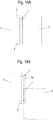
- FIGS 14A and 14B a further embodiment of a body 2 is shown, on which a door 3 can be pivoted into a first opening position in order to then lower it.
- two hinges 4 are provided, which are fixed to the body 2. If the door 3 is now from the raised position to the lowered position of the Figure 14B lowered, the hinges 4 remain stationary on the body 2, and a stationary rail 70 remains on the upper hinge 4. Relative to the stationary rail 70, the guide rail 7 is moved downwards together with the door 3.
- the guide rail 7 and the further rail 70 thus form one Pull-out guide, which can comprise two or three rails, which are movably held against one another via rolling elements or rollers. In this embodiment, too, the greater distance between the hinges 4 on the body 2 has a positive effect on the leverage.
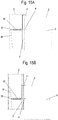
- FIG. 15A to 15C a further embodiment of an energy store is shown to preload the door 3 in a raised position.
- the energy accumulator shown schematically comprises a guide track 30 which is fixed, for example, on one or both inner sides of the side walls 20 of the body 2.
- a guide roller 31 rolls off the guide track 30, which is acted upon by force by a spring 32 which is supported at the end in the area of the lower hinge 4, so that when the door 3 moves from a raised position according to FIG Figure 15A in a slightly lowered position according to Figure 15B the guide roller 31 moves along the guide track 30 and the spring 32 is thereby compressed.
- the spring 32 is compressed even more, as shown in FIG Figure 15C is shown.
- a latching receptacle can be provided on the guide track 30 so that the door 3 can be latched in a lowered position.
- a locking device can also be used which prevents the door 3 from being lifted.
- Such latching or locking devices can be designed with mechanical elements such as latching hooks, latching receptacles, locking bolts, etc., and the position of the latching device can be selected variably within the body 2.
- Figure 16A is the embodiment of Figures 15 modified in such a way that the guide track 30 is arranged to be adjustable in order to set the force of the energy accumulator in the form of a spring 32 for lifting the door 3 relative to the body 2.
- the guide track 30 can be moved along two linear adjusting elements 33 in the horizontal direction, for example in order to be moved from this first position with solid lines to a position in which the guide track 30 'is shown with dashed lines.
- the spring 32 is compressed, and higher forces act to lift the door 3.
- the linear adjusting element is preferably designed as a linear guide. The adjustment can take place continuously in order to compress or relax the spring 32.
- FIG 16B an alternative embodiment is shown in order to be able to adjust the force of the spring 32 for lifting the door.
- a switching element 35 is provided, for example a pivotable lever or a slide which compresses or relaxes the spring 32.
- the switchover element 35 can be transferred via a pivot axis 36 into the position of the switchover element 35 ′ shown in dashed lines.
- Other adjustment mechanisms such as, for example, screw gears, coupling gears, cam gears or the like, for changing the force of the spring 32 for setting the pretension for lifting the door 3 can also be provided.
- the two embodiments of the Figure 16A and 16B can also be combined with each other.
- a self-closing mechanism can also be provided, by means of which the door 3 can be pivoted from the first open position, in which it is raised, into a closed position.
- a self-closing mechanism can comprise an energy store, in particular a spring, which automatically moves the door 3 from the first open position into the closed position.
- a damper can be provided before the closed position is reached in order to enable the door 3 to move automatically without loud noises.
- the energy store for lifting the door 3 can be used to enable the door 3 to be automatically moved into the raised first open position in order to then automatically pivot the door 3 into the closed position. The user can then automatically pivot the door 3 from a lowered position, which, however, must be unlocked or unlatched, into the raised position and then in the raised position into the closed position.
- the door 3 is mechanically preloaded by an energy storage device. It is of course also possible to provide a drive for the corresponding movements, in particular an electric motor drive. A corresponding movement can be generated, for example, via a spindle on which a spindle nut is moved, which is fixed with a structural unit on the body 2 or the door 3. Other drive devices can also be used.
Landscapes
- Engineering & Computer Science (AREA)
- Mechanical Engineering (AREA)
- Civil Engineering (AREA)
- Structural Engineering (AREA)
- Closing And Opening Devices For Wings, And Checks For Wings (AREA)
- Cabinets, Racks, Or The Like Of Rigid Construction (AREA)
- Combinations Of Kitchen Furniture (AREA)
- Refrigerator Housings (AREA)
Description
Die vorliegende Erfindung betrifft ein Schrankmöbel oder Haushaltsgerät, insbesondere als Hängeschrank, nach dem Oberbegriff des Anspruches 1.The present invention relates to a cabinet or household appliance, in particular as a wall cabinet, according to the preamble of
Die
Die
Es ist daher Aufgabe der vorliegenden Erfindung, ein Schrankmöbel oder Haushaltsgerät zu schaffen, mit dem ein Stauraum an einem Schrankmöbel oder Haushaltsgerät gerade im oberen Bereich besser genutzt wird.It is therefore the object of the present invention to create a cabinet or household appliance with which a storage space on a cabinet or household appliance is better used, especially in the upper area.
Diese Aufgabe wird mit einem Schrankmöbel oder Haushaltsgerät mit den Merkmalen des Anspruches 1 gelöst.This object is achieved with a cabinet or household appliance with the features of
Bei dem erfindungsgemäßen Schrankmöbel oder Haushaltsgerät ist eine Tür relativ zu dem Korpus verschwenkbar und kann somit von einer Schließposition in eine erste Öffnungsposition verschwenkt werden. Diese erste Öffnungsposition befindet sich in einem Öffnungsbereich der Tür, und in dem Öffnungsbereich kann die Tür entlang einer Führungseinrichtung nach unten abgesenkt werden. Dadurch kann der mindestens eine Halter zur Bevorratung von Gegenständen in den Zugriffsbereich eines Benutzers gebracht werden, der dann aus oder von dem Halter Gegenstände entnehmen oder zurückstellen kann. Anschließend kann die Tür über die Führungseinrichtung wieder angehoben und von dem Öffnungsbereich in eine Schließposition verschwenkt werden. Dies ermöglicht eine effektive Nutzung eines oberen Bereiches eines Schrankmöbels oder Haushaltsgerätes, der ansonsten schlecht zugänglich ist, beispielsweise weil der obere Bereich nicht mehr im Zugriffsbereich einer Person liegt.In the cabinet furniture or household appliance according to the invention, a door can be pivoted relative to the body and can thus be pivoted from a closed position into a first open position. This first opening position is located in an opening area of the door, and in the opening area the door can be lowered downwards along a guide device. As a result, the at least one holder for storing objects can be brought into the access area of a user who can then remove or put back objects from or from the holder. The door can then be lifted up again using the guide device be pivoted from the opening area to a closed position. This enables an effective use of an upper area of a cabinet or household appliance, which is otherwise difficult to access, for example because the upper area is no longer within the reach of a person.
Erfindungsgemäß ist die Führungseinrichtung als Linearführung ausgebildet. Die Linearführung kann dabei mehrere Schienen umfassen, die relativ zueinander verfahrbar sind. Alternativ kann auch nur eine Führungsschiene vorgesehen sein, entlang der ein Schlitten über Wälzkörper oder Rollen verfahrbar ist, um ein lineares Bewegen der Tür in vertikale Richtung zu ermöglichen.According to the invention, the guide device is designed as a linear guide. The linear guide can include several rails that can be moved relative to one another. Alternatively, only one guide rail can be provided along which a slide can be moved by means of rolling elements or rollers in order to enable the door to be moved linearly in the vertical direction.
Gemäß einer bevorzugten Ausgestaltung ist eine erste Sperreinrichtung vorgesehen, die in einem Schließbereich der Tür ein Absenken der Tür verhindert. Die Tür mit dem Halter an einer Innenseite muss zunächst eine vorbestimmte Öffnungsposition erreichen, um ein Anschlagen des Halters an dem Korpus oder an einem Einlegeboden in dem Korpus zu verhindern. Die erste Sperreinrichtung kann zumindest in einem Schließbereich zwischen der Schließposition und einem Öffnungswinkel von 60°, insbesondere bis zu einem Bereich um 70°, ein Absenken der Tür verhindern, um ein solches Anschlagen zu vermeiden. Vorzugsweise kann auch eine zweite Sperrvorrichtung vorgesehen sein, die ein Verschwenken der Tür in einem Schließbereich verhindert, wenn sich die Tür in einer abgesenkten Position befindet. Eine solche Sperreinrichtung kann über mechanische Mittel, beispielsweise eine Anschlagsleiste, ausgebildet sein, aber auch elektronische Steuerungsmittel können als Sperreinrichtung eingesetzt werden.According to a preferred embodiment, a first locking device is provided which prevents the door from lowering in a closing area of the door. The door with the holder on an inside must first reach a predetermined opening position in order to prevent the holder from hitting the body or a shelf in the body. The first locking device can prevent the door from being lowered at least in a closing area between the closed position and an opening angle of 60 °, in particular up to an area around 70 °, in order to avoid such a hitting. A second locking device can preferably also be provided which prevents the door from pivoting in a closing area when the door is in a lowered position. Such a locking device can be formed by mechanical means, for example a stop bar, but electronic control means can also be used as a locking device.
Die Tür ist erfindungsgemäß über einen Kraftspeicher in eine angehobene Position vorgespannt. Als Kraftspeicher können Federelemente, insbesondere Gasdruckfedern oder andere Federn, eingesetzt werden, oder Gegengewichte, die über Verbindungsmittel mit der Tür gekoppelt sind, so dass bei einem Absenken der Tür das Gegengewicht angehoben wird. Durch den Kraftspeicher kann die Tür bis zu einer bestimmten Zuladung auch selbsttätig in die angehobene Position bewegt werden, so dass der Nutzer nur dann eine Kraft aufbringen muss, wenn die Tür von der angehobenen Position in eine abgesenkte Position heruntergezogen wird, was die Handhabung vereinfacht, da ein Absenken einfacher als ein Anheben ist. Die Kraftunterstützung kann nicht nur zum Anheben der Tür in die angehobene Position genutzt werden, sondern auch zum Bewegen der Tür von der angehobenen Position in die Schließposition, indem zum Beispiel eine Selbsteinzugsvorrichtung auf die Tür einwirkt.According to the invention, the door is biased into a raised position via an energy storage mechanism. Spring elements, in particular gas pressure springs or other springs, or counterweights that are coupled to the door via connecting means, so that the counterweight is raised when the door is lowered, can be used as energy storage devices. Thanks to the energy store, the door can also be automatically moved into the raised position up to a certain load, so that the user only has to apply force when the door is pulled down from the raised position into a lowered position, which simplifies handling, because lowering is easier than lifting. The power assistance can be used not only to lift the door into the raised position, but also to move the door from the raised position into the closed position, for example by acting on the door by a self-closing device.
In einer ersten erfindungsgemäßen Ausgestaltung ist der Kraftspeicher zum Vorspannen der Tür in eine angehobene Position hinsichtlich der Kraft einstellbar. Dadurch können Gewichtskräfte, die aus dem Türgewicht und/oder der Zuladung resultieren, kompensiert werden. Auch unterschiedliche Türdimensionen und/oder toleranzbedingte abweichende Federkräfte lassen sich damit kompensieren, um letztlich die Tür in ein Gleichgewicht zu bringen bzw. im Gleichgewicht zu halten. Hierfür können an dem Kraftspeicher entsprechende Stellelemente vorgesehen sein, wobei der Kraftspeicher beispielsweise als Federpaket oder Feder, insbesondere als Druckfeder, ausgebildet ist. Alternativ oder zusätzlich kann in einer zweiten erfindungsgemäßen Ausgestaltung eine Führungsbahn in der Position verstellt werden, um ein Führungselement, insbesondere eine Führungsrolle, die entlang der Führungsbahn verfahrbar ist und durch den Kraftspeicher zu der Führungsbahn hin vorgespannt ist, hinsichtlich der wirkenden Kraft zu verändern.In a first embodiment according to the invention, the force storage device is used for prestressing the door in a raised position with regard to the force adjustable. In this way, weight forces resulting from the door weight and / or the load can be compensated. Different door dimensions and / or tolerance-related deviating spring forces can also be compensated for in order to ultimately bring the door into equilibrium or keep it in equilibrium. For this purpose, corresponding actuating elements can be provided on the energy storage device, the energy storage device being designed, for example, as a spring assembly or spring, in particular as a compression spring. Alternatively or additionally, in a second embodiment according to the invention, a guide track can be adjusted in position in order to change a guide element, in particular a guide roller, which can be moved along the guide track and is pretensioned towards the guide track by the energy storage device, with regard to the force acting.
Für eine besonders effiziente Nutzung des Innenraumes eines Schrankmöbels oder Haushaltsgerätes können in dem Korpus in einem unteren Bereich ein Boden und mindestens ein Einlegeboden angeordnet sein, während in einem oberen Bereich eine Aufnahme für den Halter an der Tür ausgebildet ist. Im unteren Bereich ist meist ein Zugriff für den Benutzer möglich, insbesondere wenn das Schrankmöbel als Oberschrank in einer Küche eingesetzt wird. Dann können ein Boden und mindestens ein Einlegeboden zur Bevorratung von Gegenständen dienen, die wie bei bekannten Möbeln nach dem Öffnen der Tür zugänglich gemacht werden. Lediglich in einem oberen Bereich, beispielsweise ab einer Höhe ab 1,80 m, kann statt Einlegeböden eine Aufnahme für einen oder mehrere Halter vorgesehen sein, die dann zusammen mit der Tür bewegt werden. Der Halter kann dabei als Schale, Korb, Haken oder Halteleiste ausgebildet sein, wobei alle Einrichtungen zum Halten und Bevorraten von Gegenständen an der Tür fixiert werden können.For a particularly efficient use of the interior of a cabinet or household appliance, a base and at least one shelf can be arranged in the body in a lower area, while a receptacle for the holder on the door is formed in an upper area. In the lower area, access for the user is usually possible, especially if the cabinet is used as a wall unit in a kitchen. A base and at least one shelf can then be used to store items that are made accessible after opening the door, as is the case with known furniture. Only in an upper area, for example from a height of 1.80 m or more, can a receptacle for one or more holders be provided instead of shelves, which are then moved together with the door. The holder can be designed as a bowl, basket, hook or holding bar, whereby all devices for holding and storing objects can be fixed on the door.
Die Schwenkeinrichtung für die Tür umfasst vorzugsweise mindestens zwei in vertikale Richtung voneinander beabstandete Scharniere. Die Scharniere können dabei als Eingelenk- oder Mehrgelenkscharniere, insbesondere Viergelenk- oder Siebengelenkscharniere ausgebildet sein. Auch eine Kombination aus linear wirkenden Mechaniken und Drehmechaniken zum Schwenken der Tür sind einsetzbar. Die voneinander beabstandeten Scharniere können wahlweise fest an der Tür oder dem Korpus festgelegt sein, und an dem jeweils anderen Teil verfahrbar an einem Schlitten festgelegt sein, der entlang einer Führungsschiene bewegbar ist.The pivoting device for the door preferably comprises at least two hinges which are spaced apart from one another in the vertical direction. The hinges can be designed as single-joint or multi-joint hinges, in particular four-joint or seven-joint hinges. A combination of linear mechanisms and rotary mechanisms for pivoting the door can also be used. The hinges, which are spaced apart from one another, can optionally be fixedly fixed on the door or the body, and fixed on the other part so as to be movable on a slide which can be moved along a guide rail.
Durch eine kombinierte Anordnung von Schwenkeinrichtung und Linearführung können Öffnen und Absenken der Tür in einer steten Bewegungsabfolge ablaufen, ohne dass der Benutzer seine Bedienhand vom Bediengriff nehmen und umgreifen muss. Somit ist auch ein schneller Zugriff auf in dem Halter bevorratete Gegenstände ermöglicht.A combined arrangement of the swivel device and linear guide enables the door to be opened and lowered in a constant sequence of movements without the user having to take his operating hand off the operating handle and must reach around. This also enables quick access to items stored in the holder.
In einer weiteren Ausgestaltung ist eine Verriegelungs- oder Rasteinrichtung vorgesehen, mittels der die Tür in einer abgesenkten Position verrastbar ist. Solche Rast- oder Verriegelungseinrichtungen können durch mechanische Rastelemente, wie Rasthaken, ausgebildet sein, die in einer vorbestimmten Position die Tür in der abgesenkten Position gegen die Kraft eines Kraftspeichers halten, damit der Benutzer die Tür loslassen kann und diese sich nicht selbsttätig wieder nach oben bewegt. Statt mechanischer Rastmittel können auch Steuerungsmittel eingesetzt werden, die beispielsweise per Knopfdruck für eine Fixierung der Tür in der abgesenkten Position sorgen.In a further embodiment, a locking or latching device is provided, by means of which the door can be latched in a lowered position. Such latching or locking devices can be formed by mechanical latching elements, such as latching hooks, which hold the door in a predetermined position in the lowered position against the force of an energy storage device so that the user can let go of the door and it does not automatically move up again . Instead of mechanical latching means, control means can also be used which, for example, ensure that the door is fixed in the lowered position at the push of a button.
Das Verschwenken der Tür von einer Öffnungsposition in eine Schließposition kann vollständig oder mindestens teilweise optional auch über einen Selbsteinzug erfolgen, der einen Kraftspeicher aufweist, um die Tür mechanisch in eine Schließposition vorzuspannen und somit selbsttätig eine Schließbewegung durchführen zu können. Statt eines Selbsteinzuges kann auch ein elektrischer Antrieb zum Schließen der Tür vorgesehen sein.The door can be pivoted from an open position to a closed position completely or at least partially, optionally also via a self-closing mechanism, which has an energy accumulator in order to mechanically preload the door into a closed position and thus automatically perform a closing movement. Instead of a self-closing mechanism, an electric drive can also be provided to close the door.
Bei einem Verfahren wird zunächst eine Tür von einer Schließposition in horizontale Richtung in eine erste Öffnungsposition relativ zu einem Korpus verschwenkt. Anschließend wird die Tür von der ersten Öffnungsposition in eine zweite Öffnungsposition abgesenkt, wobei die zweite Öffnungsposition unterhalb der ersten Öffnungsposition angeordnet ist und einen Zugriff auf Gegenstände ermöglicht, die an einem Halter im oberen Bereich der Tür vorgesehen sind. Danach kann die Tür von der zweiten wieder in die erste Öffnungsposition angehoben und dann von der ersten Öffnungsposition in die Schließposition verschwenkt werden. Die Bewegungen der Tür können wahlweise rein manuell erfolgen und sind durch einen oder mehrere Kraftspeicher unterstützt. Für das Anheben der Tür ist ein Kraftspeicher vorgesehen , mittels dem die Tür selbsttätig von der zweiten Offnungsposition in die erste Öffnungsposition bewegt wird. Optional kann auch ein Selbsteinzug vorgesehen sein, mittels dem die Tür selbsttätig von der ersten Öffnungsposition in die Schließposition bewegt wird, um die Handhabung zu vereinfachen. Hierzu kann weiterhin auch optional eine Dämpfungsvorrichtung angeschlossen sein, um ein gedämpftes Schließen der Tür kurz vor Erreichen der Schließposition zu ermöglichen.In one method, a door is first pivoted from a closed position in the horizontal direction into a first open position relative to a body. The door is then lowered from the first opening position into a second opening position, the second opening position being arranged below the first opening position and allowing access to objects which are provided on a holder in the upper region of the door. The door can then be raised again from the second opening position to the first opening position and then from the first opening position to the Be pivoted closed position. The movements of the door can optionally be done manually and are supported by one or more energy stores. An energy store is provided for lifting the door, by means of which the door is automatically moved from the second open position into the first open position. Optionally, a self-closing mechanism can also be provided, by means of which the door is automatically moved from the first open position into the closed position in order to simplify handling. For this purpose, a damping device can also optionally be connected in order to enable the door to be closed in a damped manner shortly before the closed position is reached.
Die Erfindung wird nachfolgend anhand eines Ausführungsbeispiels mit Bezug auf die beigefügten Zeichnungen näher erläutert. Es zeigen:
Figur 1- eine perspektivische Ansicht eines erfindungsgemäßen Schrankmöbels mit teilweise weggelassener Tür;
Figur 2- eine perspektivische Ansicht des Schrankmöbels der
Figur 1 Figur 3- eine perspektivische Ansicht des Schrankmöbels der
Figur 1 Figur 4- eine Draufsicht auf das Möbel der
Figur 3 Figur 5- eine perspektivische Ansicht des Schrankmöbels der
Figur 2 ; Figur 6- eine Draufsicht auf die Schwenkeinrichtung des Schrankmöbels der
Figur 1 in einer Schließposition; Figur 7- eine Detailansicht der Schwenkeinrichtung gemäß Figur 6 in einer ersten Öffnungsposition;
Figur 8- eine perspektivische Ansicht des Schrankmöbels der
Figur 1 von hinten; Figuren 9 und 10- zwei Detailansichten des Seilzuges für den Kraftspeicher zum Anheben der Tür;
- Figuren 11A und 11B
- zwei schematische Ansichten zum Funktionsprinzip des ersten Ausführungsbeispiels;
- Figuren 12A und 12B
- zwei schematische Ansichten zum Funktionsprinzip eines zweiten Ausführungsbeispiels;
- Figuren 13A und 13B
- zwei schematische Ansichten zum Funktionsprinzip eines dritten Ausführungsbeispiels;
- Figuren 14A und 14B
- zwei schematische Ansichten zum Funktionsprinzip eines vierten Ausführungsbeispiels,;
- Figuren 15A bis 15C
- mehrere schematische Ansichten eines weiteren Ausführungsbeispiels mit modifiziertem Kraftspeicher, und
- Figuren 16A und 16B
- zwei Ansichten mit Ausführungsformen zum Einstellen der Kraft zum Anheben der Tür.
- Figure 1
- a perspective view of a cabinet according to the invention with a partially omitted door;
- Figure 2
- a perspective view of the cabinet furniture
Figure 1 with the door in the first open position; - Figure 3
- a perspective view of the cabinet furniture
Figure 1 with the door in a second, lowered, open position; - Figure 4
- a top view of the furniture of the
Figure 3 ; - Figure 5
- a perspective view of the cabinet furniture
Figure 2 ; - Figure 6
- a plan view of the swivel device of the cabinet
Figure 1 in a closed position; - Figure 7
- a detailed view of the pivoting device according to Figure 6 in a first opening position;
- Figure 8
- a perspective view of the cabinet furniture
Figure 1 from behind; - Figures 9 and 10
- two detailed views of the cable for the energy storage device for lifting the door;
- Figures 11A and 11B
- two schematic views of the functional principle of the first embodiment;
- Figures 12A and 12B
- two schematic views of the functional principle of a second embodiment;
- Figures 13A and 13B
- two schematic views of the functional principle of a third embodiment;
- Figures 14A and 14B
- two schematic views of the functional principle of a fourth exemplary embodiment;
- Figures 15A to 15C
- several schematic views of a further exemplary embodiment with a modified energy store, and
- Figures 16A and 16B
- two views with embodiments for adjusting the force for lifting the door.
Ein Schrankmöbel 1 umfasst einen Korpus 2, der beispielsweise als Oberschrank an einer Küchenzeile montiert werden kann. Alternativ kann der Korpus 2 auch für ein Haushaltsgerät eingesetzt werden, beispielsweise einen Kühlschrank. An dem Korpus 2 ist eine Tür 3 verschwenkbar gelagert, wobei die Tür 3 plattenförmig ausgebildet ist und an der Außenseite ein Griffelement 8 aufweist. An der Tür 3 ist eine Schwenkeinrichtung mit zwei Scharnieren 4 festgelegt, zwischen denen eine Leiste 5 vorgesehen ist. An der Tür 3 ist an der Innenseite ein Halter 6 in Form eines Korbes oder eines Gitters vorgesehen, der zur Bevorratung von Gegenständen dient. An der Tür 3 können im oberen Bereich, also in der oberen Hälfte der Tür, ein oder mehrere dieser Halter 6 vorgesehen sein, die zusammen mit der Tür 3 bewegt werden können. In einem unteren Bereich des Korpus 2 sind an dem Korpus 2 Gegenstände auf einem Boden oder einem nicht dargestellten Einlegeboden abstellbar, da der untere Bereich vom Benutzer aus auch im Stehen zugänglich ist.A
In
In
Der Korpus 2 umfasst neben dem Boden 22 einen Oberboden 23, die zwischen zwei Seitenwänden 20 angeordnet sind. Die Seitenwände 20 sowie der Boden 22 und Oberboden 23 sind rückseitig durch eine Rückwand 21 miteinander verbunden, die beabstandet von einer rückseitigen Stirnkante der Seitenwände 20 montiert ist, um hinter der Rückwand 21 einen Raum für Bauteile zu schaffen, beispielsweise für einen Kraftspeicher.In addition to the
In
Die Funktion der Sperreinrichtung für die Tür 3 wird mit Bezug auf die
Die Tür 3 des Schrankmöbels 1 ist in einer angehobenen Position vorgespannt. Hierfür ist hinter der Rückwand 21 ein Gegengewicht 18 angeordnet, das über einen Seilzug 13 bewegbar ist. Das Gegengewicht 18 ist an der Rückseite des Korpus 2 entlang von Schienen 24 geführt, die an gegenüberliegenden Seitenwänden 20 vorgesehen sind. Ferner ist das Gegengewicht 18 mittig an dem Seilzug 13 aufgehängt, wobei der Seilzug 13 an der Rückseite über eine erste Umlenkrolle 16 und eine zweite Umlenkrolle 17 geführt ist, die drehbar an Haltern gelagert sind (
Wie die
Statt der Ausbildung des Kraftspeichers durch ein Gegengewicht 18 können natürlich auch andere Federelemente eingesetzt werden, insbesondere Gasdruckfedern, Spiralfedern oder andere Federeinrichtungen, um die Tür 3 nach oben vorzuspannen. Die Vorspannung der Tür 3 kann beispielsweise so gewählt werden, dass eine Beladung der Tür 3 mit einem Gewicht von bis zu 10 kg möglich ist und die Tür 3 immer noch nach oben vorgespannt ist. Dadurch kann die Tür 3 über den Kraftspeicher auch selbsttätig von der abgesenkten Position in eine angehobene Position bewegt werden. Vor Erreichen eines Anschlages kann zudem eine Dämpfungseinrichtung vorgesehen sein, um ein lautes Anschlagen bei einer vertikalen Bewegung nach oben zu vermeiden.Instead of forming the energy store by a
In den
Wie in den
In den
In den
Bei den schematischen Darstellungen der Ausführungsbeispiele der
In den
In
In
Bei den dargestellten Ausführungsbeispielen kann ferner ein Selbsteinzug vorgesehen sein, mittels dem die Tür 3 von der ersten Öffnungsposition, in der sie angehoben ist, in eine Schließstellung verschwenkt werden. Ein solcher Selbsteinzug kann einen Kraftspeicher umfassen, insbesondere eine Feder, der die Tür 3 von der ersten Öffnungsposition automatisch in die Schließposition bewegt. Um Anschlaggeräusche zu vermeiden, kann vor Erreichen der Schließposition ein Dämpfer vorgesehen sein, um ein selbsttätiges Bewegen der Tür 3 ohne laute Geräusche zu ermöglichen. Zusätzlich zu dem Selbsteinzug kann der Kraftspeicher zum Anheben der Tür 3 dazu eingesetzt werden, ein selbsttätiges Verfahren der Tür 3 in die angehobene erste Öffnungsposition zu ermöglichen, um dann selbsttätig ein Verschwenken der Tür 3 bis in die Schließposition zu bewirken. Der Benutzer kann dann die Tür 3 aus einer abgesenkten Position, die allerdings entriegelt bzw. entrastet sein muss, selbsttätig in die angehobene Position und dann in der angehobenen Position in die Schließposition verschwenken.In the illustrated exemplary embodiments, a self-closing mechanism can also be provided, by means of which the
In den dargestellten Ausführungsbeispielen wird die Tür 3 mechanisch durch Kraftspeicher vorgespannt. Es ist natürlich auch möglich, einen Antrieb für die entsprechenden Bewegungen vorzusehen, insbesondere einen elektromotorischen Antrieb. Eine entsprechende Bewegung kann beispielsweise über eine Spindel generiert werden, auf der eine Spindelmutter verfahren wird, die mit einer Baueinheit an dem Korpus 2 oder der Tür 3 festgelegt ist. Auch andere Antriebseinrichtungen können eingesetzt werden.In the illustrated embodiments, the
- 11
- SchrankmöbelCabinet furniture
- 22
- KorpusBody
- 33rd
- Türdoor
- 44th
- Scharnierhinge
- 55
- Leistestrip
- 66th
- Halterholder
- 77th
- FührungsschieneGuide rail
- 88th
- GriffelementHandle element
- 99
- Schlittensleds
- 1010
- SperrleisteLocking bar
- 1111
- Hebellever
- 1212th
- AnschlagselementStop element
- 1313th
- SeilzugCable
- 1414th
- BefestigungselementFastener
- 1515th
- UmlenkrollePulley
- 1616
- UmlenkrollePulley
- 1717th
- UmlenkrollePulley
- 1818th
- GegengewichtCounterweight
- 1919th
- Schlittensleds
- 2020th
- SeitenwandSide wall
- 2121
- RückwandBack wall
- 2222nd
- Bodenfloor
- 2323
- OberbodenTopsoil
- 2424
- Schienerail
- 30,30'30.30 '
- FührungsbahnGuideway
- 3131
- FührungsrolleLeadership role
- 3232
- Federfeather
- 3333
- StellelementControl element
- 35,35'35.35 '
- UmschaltelementSwitching element
- 3636
- SchwenkachseSwivel axis
- 4040
- ScharnierteilHinge part
- 4141
- ScharnierteilHinge part
- 4242
- SchlepphebelRocker arm
- 7070
- Schienerail
Claims (10)
- A cupboard (1) or household appliance, in particular as a hanging cabinet, having a body (2) on which a door (3) is pivotable via a pivot device (4) from a closed position into an open position, wherein at least one holder (6) for storing objects is fixed on an inner side of the door (3) facing toward the body (2), wherein the door (3) is lowerable along a guide device (7) into an opening range of the door (3), wherein the guide device (7) is designed as a linear guide comprising a plurality of rails being arranged movably with regard to each other or a guide rail on which a carriage (9, 19) is held so it is movable via roller bodies or rolls, in order to enable linear movement of the door (3) in the vertical direction, and the door (3) is pre-tensioned via a force accumulator (18, 32) in a raised position, characterized in that, in order to set the force of the force accumulator (32), a guide path (30) is adjustable, along which the guide roller (31) or guide element pre-tensioned by the force accumulator (32) is movable, or the force accumulator (32) is designed as a spring and setting means (33, 35) are provided for changing the pre-tension of the spring.
- The cupboard or household appliance according to Claim 1, characterized in that a first blocking device (10, 11) is provided, which prevents lowering of the door (3) in a closing range of the door (3).
- The cupboard or household appliance according to Claim 2, characterized in that the first blocking device (10, 11) is active at least in a closing range between the closed position and an opening angle of 60°, in particular 70°.
- The cupboard or household appliance according to any one of the preceding claims, characterized in that a second blocking device (10, 11) is provided, which prevents pivoting of the door from an open position into a closing range if the door (3) is arranged in a lowered position.
- The cupboard or household appliance according to any one of the preceding claims, characterized in that a bottom panel (22) and optionally at least one shelf are arranged in the body (2) in a lower region and a free space for a receptacle for the holder (6) is formed in an upper region.
- The cupboard or household appliance according to any one of the preceding claims, characterized in that the holder (6) comprises a shell, a basket, a hook, and/or a holding bracket.
- The cupboard or household appliance according to any one of the preceding claims, characterized in that the pivot device (4) comprises at least two hinges arranged spaced apart from one another in the vertical direction.
- The cupboard or household appliance according to Claim 7, characterized in that the hinges are secured on the door (3) and/or are movable on a carriage along a guide rail.
- The cupboard or household appliance according to any one of the preceding claims, characterized in that a locking or latching device is provided, by means of which the door (3) can be latched or locked in a lowered position.
- The cupboard or household appliance according to any one of the preceding claims, characterized in that a self-retractor is provided, by means of which the door (3) is pivotable from an open position into a closed position.
Applications Claiming Priority (2)
| Application Number | Priority Date | Filing Date | Title |
|---|---|---|---|
| DE102017104336.5A DE102017104336A1 (en) | 2017-03-02 | 2017-03-02 | Cabinet furniture or household appliance and method for opening and closing cabinet furniture or household appliance |
| PCT/EP2018/054013 WO2018158100A1 (en) | 2017-03-02 | 2018-02-19 | Cupboard or household appliance and method for opening and closing a cupboard or household appliance |
Publications (2)
| Publication Number | Publication Date |
|---|---|
| EP3589159A1 EP3589159A1 (en) | 2020-01-08 |
| EP3589159B1 true EP3589159B1 (en) | 2021-09-15 |
Family
ID=61526780
Family Applications (1)
| Application Number | Title | Priority Date | Filing Date |
|---|---|---|---|
| EP18708066.8A Active EP3589159B1 (en) | 2017-03-02 | 2018-02-19 | Cupboard or household appliance |
Country Status (6)
| Country | Link |
|---|---|
| US (1) | US11234512B2 (en) |
| EP (1) | EP3589159B1 (en) |
| JP (1) | JP7049358B2 (en) |
| CN (1) | CN110352023B (en) |
| DE (1) | DE102017104336A1 (en) |
| WO (1) | WO2018158100A1 (en) |
Families Citing this family (8)
| Publication number | Priority date | Publication date | Assignee | Title |
|---|---|---|---|---|
| PL3569806T3 (en) * | 2018-05-17 | 2022-01-17 | Kesseböhmer Holding Kg | Lid fitting for swingable mounting of a furniture lid to a furniture unit |
| FR3086851B1 (en) * | 2018-10-03 | 2020-10-09 | O C An S | ERGONOMIC STORAGE CABINET |
| CN113727627B (en) * | 2019-03-08 | 2024-12-03 | W·黑尔德 | Swivel cupboard pull-out element |
| US11286698B2 (en) * | 2019-06-27 | 2022-03-29 | Bsh Home Appliances Corporation | Cooking appliance having a load-bearing door |
| DE102019119295B3 (en) * | 2019-07-16 | 2021-01-21 | ambigence GmbH & Co. KG | Furniture component |
| CN113133592B (en) * | 2021-04-21 | 2022-06-14 | 湖南捷西整体家居有限公司 | Full-automatic intelligent article storage cabinet |
| US12130004B2 (en) | 2021-07-13 | 2024-10-29 | Kohler Co. | Mirror and cabinet apparatus |
| USD1064653S1 (en) | 2022-07-06 | 2025-03-04 | Kohler Co. | Cabinet |
Family Cites Families (44)
| Publication number | Priority date | Publication date | Assignee | Title |
|---|---|---|---|---|
| US333622A (en) * | 1886-01-05 | Adam milleb gasman | ||
| US806277A (en) * | 1905-05-29 | 1905-12-05 | Watson William Mckee | Store-cabinet. |
| US1253655A (en) * | 1916-06-12 | 1918-01-15 | Fred Wiederrecht | Gate-hinge. |
| US1255291A (en) * | 1917-04-18 | 1918-02-05 | Allen Smith Chalfant | Adjustable hinge. |
| US1720050A (en) * | 1928-03-27 | 1929-07-09 | Grand Rapids Store Equip Co | Disappearing door structure |
| US3078133A (en) | 1956-11-13 | 1963-02-19 | Wilbert E Schauer | Pivotally and vertically movable shelf structure |
| US3101982A (en) * | 1958-11-14 | 1963-08-27 | Kurt J Dosmar | Cabinet with shiftable shelves |
| US3099866A (en) * | 1961-07-17 | 1963-08-06 | Joseph P Matranga | Window structure |
| US3081138A (en) | 1961-10-16 | 1963-03-12 | Leo A Stebbins | Lowerable compartment for cabinets |
| US3172715A (en) * | 1963-02-14 | 1965-03-09 | Gen Motors Corp | Adjustable refrigerator shelf |
| US3224827A (en) * | 1963-11-12 | 1965-12-21 | Winco Inc | Cabinet hardware for lowering and retracting a container |
| US4403449A (en) * | 1980-03-03 | 1983-09-13 | Richmond Moscow K | Gate-opening and closing apparatus and method |
| DE3215572A1 (en) | 1982-04-27 | 1983-10-27 | Hermann 4905 Spenge Dröge | Upper cabinet with a lowerable insert basket |
| JPS59149110A (en) * | 1983-02-15 | 1984-08-27 | ブラザー工業株式会社 | Elevating type shelf |
| US4639051A (en) * | 1985-03-25 | 1987-01-27 | Amerock Corporation | Turn-out shelf assembly for a cabinet |
| ATA112985A (en) * | 1985-04-16 | 1991-05-15 | Grass Alfred Metallwaren | FITTING FOR A CABINET WITH DOOR ON THE FRONT |
| JPH0427384Y2 (en) | 1989-03-01 | 1992-07-01 | ||
| JP2523904Y2 (en) * | 1990-05-15 | 1997-01-29 | クリナップ株式会社 | Rotating shelf with lifting function |
| US5330261A (en) * | 1992-02-10 | 1994-07-19 | Bennett James L | Cooler door display rack |
| US5228763A (en) * | 1992-03-30 | 1993-07-20 | Lawrence Gingold | Extendable storage element |
| TWM250594U (en) * | 1997-03-31 | 2004-11-21 | Matsushita Electric Ind Co Ltd | Elevating accepting apparatus |
| US6318824B1 (en) * | 1998-10-29 | 2001-11-20 | Lucent Technologies, Inc. | Hinged tracking system |
| DE20315920U1 (en) | 2003-10-16 | 2004-02-12 | Johannes Brockmann Gmbh & Co Kg | Wall cupboard, particularly for use by disabled people, is mounted in frame with inverted U shape which has slanting U-profile guides on its side arms, along which plastic blocks attached to cupboard walls slide |
| DE202005006019U1 (en) | 2005-02-14 | 2005-11-24 | Blech, Erich | Inner shelf unit for kitchen wall cupboards is mounted on diagonal slides and can be lowered by motor connected to cable with counterweight on other end |
| PL373541A1 (en) * | 2005-03-10 | 2006-09-18 | Włodzimierz Śmieszek | Furniture container cover transfer mechanism |
| ITMC20050018U1 (en) * | 2005-09-30 | 2007-04-01 | Compagnucci Spa | FLUSHING AND REVOLVING BUILT-IN ELEMENT FOR CORNER UNITS OF MODULAR FURNITURE. |
| US20070159037A1 (en) * | 2006-01-10 | 2007-07-12 | Knape & Vogt Manufacturing Company | Hinge bracket for a pocket door |
| ES2311418B1 (en) * | 2007-07-27 | 2010-01-05 | Enrique Lago Palacios | PERFECTED GUILLOTINE WINDOW. |
| US7770986B1 (en) * | 2007-09-20 | 2010-08-10 | Vaidotas Joseph Simaitis | Overhead pull-out swing-down drawer |
| US7922268B2 (en) * | 2008-05-23 | 2011-04-12 | Peka-Metall Ag | Cupboard installation part with storage compartments, which part is insertable in an upper cupboard |
| US8297722B2 (en) * | 2008-06-03 | 2012-10-30 | Rev-A-Shelf Company, Llc | Soft close drawer assembly and bracket |
| JP5199144B2 (en) * | 2009-02-10 | 2013-05-15 | クリナップ株式会社 | Storage |
| US9677317B2 (en) * | 2009-03-03 | 2017-06-13 | The Chamberlain Group, Inc. | Variable speed movable barrier operator |
| EP2353436B1 (en) * | 2010-02-05 | 2012-11-14 | Hetal-Werke Franz Hettich GmbH & Co. | Fitting for a corner cupboard and corner cupboard |
| US8414093B2 (en) * | 2010-04-30 | 2013-04-09 | Eric M. Moran | Motorized moveable shelf assembly for cabinet structures |
| JP5595896B2 (en) | 2010-12-21 | 2014-09-24 | パナソニック株式会社 | Lifting storage device |
| CN102160713A (en) * | 2011-02-18 | 2011-08-24 | 樊刚 | Hanging cabinet capable of sliding upward and downward |
| CN202227847U (en) * | 2011-05-26 | 2012-05-23 | 吴方兴 | A sliding device for a closet door |
| ES2886543T3 (en) * | 2012-12-05 | 2021-12-20 | Hawa Sliding Solutions Ag | Guide device for movable and rotatable separating elements and functional unit |
| DE202013003188U1 (en) * | 2013-04-08 | 2014-07-10 | Grass Gmbh & Co. Kg | Device for controlling movement of a furniture part and furniture with such a device |
| JP6224951B2 (en) | 2013-08-12 | 2017-11-01 | 株式会社ニフコ | Hanging cupboard |
| US8966713B1 (en) * | 2013-12-06 | 2015-03-03 | Barrette Outdoor Living, Inc. | Adjustable self-closing fence hinge |
| CN204260193U (en) * | 2014-12-07 | 2015-04-15 | 孙存霞 | Wall-hanging Western medicine storage cabinet |
| KR102474607B1 (en) * | 2017-09-11 | 2022-12-06 | 현대자동차주식회사 | Coach door of vehicle capable of opening and closing regardless of order |
-
2017
- 2017-03-02 DE DE102017104336.5A patent/DE102017104336A1/en active Pending
-
2018
- 2018-02-19 JP JP2019547368A patent/JP7049358B2/en active Active
- 2018-02-19 US US16/489,430 patent/US11234512B2/en active Active
- 2018-02-19 WO PCT/EP2018/054013 patent/WO2018158100A1/en unknown
- 2018-02-19 EP EP18708066.8A patent/EP3589159B1/en active Active
- 2018-02-19 CN CN201880014957.8A patent/CN110352023B/en active Active
Also Published As
| Publication number | Publication date |
|---|---|
| JP7049358B2 (en) | 2022-04-06 |
| EP3589159A1 (en) | 2020-01-08 |
| CN110352023A (en) | 2019-10-18 |
| US11234512B2 (en) | 2022-02-01 |
| CN110352023B (en) | 2021-06-25 |
| US20190380487A1 (en) | 2019-12-19 |
| WO2018158100A1 (en) | 2018-09-07 |
| DE102017104336A1 (en) | 2018-09-06 |
| JP2020509269A (en) | 2020-03-26 |
Similar Documents
| Publication | Publication Date | Title |
|---|---|---|
| EP3589159B1 (en) | Cupboard or household appliance | |
| EP3707330B1 (en) | Wing fitting for a piece of furniture, side wall of a body of a piece of furniture and piece of furniture comprising a side wall | |
| EP1861572B1 (en) | Furniture | |
| EP2702219B1 (en) | Furniture item having a furniture body and a folding flap | |
| EP2250929B1 (en) | Cupboard section with extricable section | |
| EP3654803B2 (en) | Furniture with a coffe machine or a toaster and method for opening a door | |
| WO2008135270A1 (en) | Fitting for a corner cupboard comprising a pull-out single-part shelf | |
| WO2015155118A1 (en) | Item of furniture or household appliance, and fitting unit for an item of furniture or a househould appliance | |
| EP3399127B1 (en) | Furniture fitting for a sliding motion of a multipart door and furniture with such a fitting for furniture | |
| DE102017126366A1 (en) | Flap fitting for a furniture, side wall of a furniture body and furniture with a side wall | |
| DE102011085177B4 (en) | Drive system for a motor vehicle roof system | |
| EP3641619B1 (en) | Domestic dishwasher | |
| EP3487359B1 (en) | Pushing-out device for a movable furniture part, and piece of furniture | |
| EP3852980B1 (en) | Storage unit for tools | |
| AT503671B1 (en) | FURNITURE | |
| DE102008040609A1 (en) | Cooling device i.e. household cooling device, for cooling and/or freezing foods, has door having degree of freedom in addition to translation degree of freedom, and trays having degree of freedom in addition to translation degree of freedom | |
| EP2976971A1 (en) | Pull-out fitting with door coupling device and storage cupboard with such a pull-out fitting | |
| EP0908592B1 (en) | Door lifting device | |
| EP3326491A1 (en) | Fitting for the mobile positioning of a shelf board in a corner cupboard by means of a cogged wheel | |
| EP1989953B1 (en) | Fitting for a corner cupboard with an extendable one-part shelf | |
| DE102007040886A1 (en) | Cabinet unit, has rotatable bracket that is guided such that lock unit is shifted into certain range of rack side wall during opening of rack front side, where bracket comprises leverage with two arms | |
| EP3531871B1 (en) | Piece of furniture and method for opening a drawer and an inner drawer | |
| DE102015120277B4 (en) | Movable furniture part, furniture, household appliance, method for opening a movable furniture part and method for closing a movable furniture part | |
| EP2453191B1 (en) | Drawer cool box | |
| EP2697463A1 (en) | Fitting set-up for sliding doors and furniture with a sliding door |
Legal Events
| Date | Code | Title | Description |
|---|---|---|---|
| STAA | Information on the status of an ep patent application or granted ep patent |
Free format text: STATUS: UNKNOWN |
|
| STAA | Information on the status of an ep patent application or granted ep patent |
Free format text: STATUS: THE INTERNATIONAL PUBLICATION HAS BEEN MADE |
|
| PUAI | Public reference made under article 153(3) epc to a published international application that has entered the european phase |
Free format text: ORIGINAL CODE: 0009012 |
|
| STAA | Information on the status of an ep patent application or granted ep patent |
Free format text: STATUS: REQUEST FOR EXAMINATION WAS MADE |
|
| 17P | Request for examination filed |
Effective date: 20190916 |
|
| AK | Designated contracting states |
Kind code of ref document: A1 Designated state(s): AL AT BE BG CH CY CZ DE DK EE ES FI FR GB GR HR HU IE IS IT LI LT LU LV MC MK MT NL NO PL PT RO RS SE SI SK SM TR |
|
| AX | Request for extension of the european patent |
Extension state: BA ME |
|
| DAV | Request for validation of the european patent (deleted) | ||
| DAX | Request for extension of the european patent (deleted) | ||
| STAA | Information on the status of an ep patent application or granted ep patent |
Free format text: STATUS: EXAMINATION IS IN PROGRESS |
|
| 17Q | First examination report despatched |
Effective date: 20200907 |
|
| STAA | Information on the status of an ep patent application or granted ep patent |
Free format text: STATUS: EXAMINATION IS IN PROGRESS |
|
| GRAP | Despatch of communication of intention to grant a patent |
Free format text: ORIGINAL CODE: EPIDOSNIGR1 |
|
| STAA | Information on the status of an ep patent application or granted ep patent |
Free format text: STATUS: GRANT OF PATENT IS INTENDED |
|
| INTG | Intention to grant announced |
Effective date: 20210409 |
|
| GRAS | Grant fee paid |
Free format text: ORIGINAL CODE: EPIDOSNIGR3 |
|
| GRAA | (expected) grant |
Free format text: ORIGINAL CODE: 0009210 |
|
| STAA | Information on the status of an ep patent application or granted ep patent |
Free format text: STATUS: THE PATENT HAS BEEN GRANTED |
|
| AK | Designated contracting states |
Kind code of ref document: B1 Designated state(s): AL AT BE BG CH CY CZ DE DK EE ES FI FR GB GR HR HU IE IS IT LI LT LU LV MC MK MT NL NO PL PT RO RS SE SI SK SM TR |
|
| REG | Reference to a national code |
Ref country code: CH Ref legal event code: EP |
|
| REG | Reference to a national code |
Ref country code: DE Ref legal event code: R096 Ref document number: 502018007075 Country of ref document: DE |
|
| REG | Reference to a national code |
Ref country code: IE Ref legal event code: FG4D Free format text: LANGUAGE OF EP DOCUMENT: GERMAN |
|
| REG | Reference to a national code |
Ref country code: AT Ref legal event code: REF Ref document number: 1429838 Country of ref document: AT Kind code of ref document: T Effective date: 20211015 |
|
| REG | Reference to a national code |
Ref country code: LT Ref legal event code: MG9D |
|
| REG | Reference to a national code |
Ref country code: NL Ref legal event code: MP Effective date: 20210915 |
|
| PG25 | Lapsed in a contracting state [announced via postgrant information from national office to epo] |
Ref country code: NO Free format text: LAPSE BECAUSE OF FAILURE TO SUBMIT A TRANSLATION OF THE DESCRIPTION OR TO PAY THE FEE WITHIN THE PRESCRIBED TIME-LIMIT Effective date: 20211215 Ref country code: LT Free format text: LAPSE BECAUSE OF FAILURE TO SUBMIT A TRANSLATION OF THE DESCRIPTION OR TO PAY THE FEE WITHIN THE PRESCRIBED TIME-LIMIT Effective date: 20210915 Ref country code: BG Free format text: LAPSE BECAUSE OF FAILURE TO SUBMIT A TRANSLATION OF THE DESCRIPTION OR TO PAY THE FEE WITHIN THE PRESCRIBED TIME-LIMIT Effective date: 20211215 Ref country code: SE Free format text: LAPSE BECAUSE OF FAILURE TO SUBMIT A TRANSLATION OF THE DESCRIPTION OR TO PAY THE FEE WITHIN THE PRESCRIBED TIME-LIMIT Effective date: 20210915 Ref country code: RS Free format text: LAPSE BECAUSE OF FAILURE TO SUBMIT A TRANSLATION OF THE DESCRIPTION OR TO PAY THE FEE WITHIN THE PRESCRIBED TIME-LIMIT Effective date: 20210915 Ref country code: HR Free format text: LAPSE BECAUSE OF FAILURE TO SUBMIT A TRANSLATION OF THE DESCRIPTION OR TO PAY THE FEE WITHIN THE PRESCRIBED TIME-LIMIT Effective date: 20210915 Ref country code: FI Free format text: LAPSE BECAUSE OF FAILURE TO SUBMIT A TRANSLATION OF THE DESCRIPTION OR TO PAY THE FEE WITHIN THE PRESCRIBED TIME-LIMIT Effective date: 20210915 |
|
| PG25 | Lapsed in a contracting state [announced via postgrant information from national office to epo] |
Ref country code: LV Free format text: LAPSE BECAUSE OF FAILURE TO SUBMIT A TRANSLATION OF THE DESCRIPTION OR TO PAY THE FEE WITHIN THE PRESCRIBED TIME-LIMIT Effective date: 20210915 Ref country code: GR Free format text: LAPSE BECAUSE OF FAILURE TO SUBMIT A TRANSLATION OF THE DESCRIPTION OR TO PAY THE FEE WITHIN THE PRESCRIBED TIME-LIMIT Effective date: 20211216 |
|
| PG25 | Lapsed in a contracting state [announced via postgrant information from national office to epo] |
Ref country code: IS Free format text: LAPSE BECAUSE OF FAILURE TO SUBMIT A TRANSLATION OF THE DESCRIPTION OR TO PAY THE FEE WITHIN THE PRESCRIBED TIME-LIMIT Effective date: 20220115 Ref country code: SM Free format text: LAPSE BECAUSE OF FAILURE TO SUBMIT A TRANSLATION OF THE DESCRIPTION OR TO PAY THE FEE WITHIN THE PRESCRIBED TIME-LIMIT Effective date: 20210915 Ref country code: SK Free format text: LAPSE BECAUSE OF FAILURE TO SUBMIT A TRANSLATION OF THE DESCRIPTION OR TO PAY THE FEE WITHIN THE PRESCRIBED TIME-LIMIT Effective date: 20210915 Ref country code: RO Free format text: LAPSE BECAUSE OF FAILURE TO SUBMIT A TRANSLATION OF THE DESCRIPTION OR TO PAY THE FEE WITHIN THE PRESCRIBED TIME-LIMIT Effective date: 20210915 Ref country code: PT Free format text: LAPSE BECAUSE OF FAILURE TO SUBMIT A TRANSLATION OF THE DESCRIPTION OR TO PAY THE FEE WITHIN THE PRESCRIBED TIME-LIMIT Effective date: 20220117 Ref country code: PL Free format text: LAPSE BECAUSE OF FAILURE TO SUBMIT A TRANSLATION OF THE DESCRIPTION OR TO PAY THE FEE WITHIN THE PRESCRIBED TIME-LIMIT Effective date: 20210915 Ref country code: NL Free format text: LAPSE BECAUSE OF FAILURE TO SUBMIT A TRANSLATION OF THE DESCRIPTION OR TO PAY THE FEE WITHIN THE PRESCRIBED TIME-LIMIT Effective date: 20210915 Ref country code: ES Free format text: LAPSE BECAUSE OF FAILURE TO SUBMIT A TRANSLATION OF THE DESCRIPTION OR TO PAY THE FEE WITHIN THE PRESCRIBED TIME-LIMIT Effective date: 20210915 Ref country code: EE Free format text: LAPSE BECAUSE OF FAILURE TO SUBMIT A TRANSLATION OF THE DESCRIPTION OR TO PAY THE FEE WITHIN THE PRESCRIBED TIME-LIMIT Effective date: 20210915 Ref country code: CZ Free format text: LAPSE BECAUSE OF FAILURE TO SUBMIT A TRANSLATION OF THE DESCRIPTION OR TO PAY THE FEE WITHIN THE PRESCRIBED TIME-LIMIT Effective date: 20210915 Ref country code: AL Free format text: LAPSE BECAUSE OF FAILURE TO SUBMIT A TRANSLATION OF THE DESCRIPTION OR TO PAY THE FEE WITHIN THE PRESCRIBED TIME-LIMIT Effective date: 20210915 |
|
| PGFP | Annual fee paid to national office [announced via postgrant information from national office to epo] |
Ref country code: FR Payment date: 20220221 Year of fee payment: 5 |
|
| REG | Reference to a national code |
Ref country code: DE Ref legal event code: R097 Ref document number: 502018007075 Country of ref document: DE |
|
| PLBE | No opposition filed within time limit |
Free format text: ORIGINAL CODE: 0009261 |
|
| STAA | Information on the status of an ep patent application or granted ep patent |
Free format text: STATUS: NO OPPOSITION FILED WITHIN TIME LIMIT |
|
| PG25 | Lapsed in a contracting state [announced via postgrant information from national office to epo] |
Ref country code: DK Free format text: LAPSE BECAUSE OF FAILURE TO SUBMIT A TRANSLATION OF THE DESCRIPTION OR TO PAY THE FEE WITHIN THE PRESCRIBED TIME-LIMIT Effective date: 20210915 |
|
| 26N | No opposition filed |
Effective date: 20220616 |
|
| PG25 | Lapsed in a contracting state [announced via postgrant information from national office to epo] |
Ref country code: SI Free format text: LAPSE BECAUSE OF FAILURE TO SUBMIT A TRANSLATION OF THE DESCRIPTION OR TO PAY THE FEE WITHIN THE PRESCRIBED TIME-LIMIT Effective date: 20210915 |
|
| PG25 | Lapsed in a contracting state [announced via postgrant information from national office to epo] |
Ref country code: MC Free format text: LAPSE BECAUSE OF FAILURE TO SUBMIT A TRANSLATION OF THE DESCRIPTION OR TO PAY THE FEE WITHIN THE PRESCRIBED TIME-LIMIT Effective date: 20210915 |
|
| REG | Reference to a national code |
Ref country code: CH Ref legal event code: PL |
|
| REG | Reference to a national code |
Ref country code: BE Ref legal event code: MM Effective date: 20220228 |
|
| PG25 | Lapsed in a contracting state [announced via postgrant information from national office to epo] |
Ref country code: LU Free format text: LAPSE BECAUSE OF NON-PAYMENT OF DUE FEES Effective date: 20220219 |
|
| PG25 | Lapsed in a contracting state [announced via postgrant information from national office to epo] |
Ref country code: LI Free format text: LAPSE BECAUSE OF NON-PAYMENT OF DUE FEES Effective date: 20220228 Ref country code: IE Free format text: LAPSE BECAUSE OF NON-PAYMENT OF DUE FEES Effective date: 20220219 Ref country code: CH Free format text: LAPSE BECAUSE OF NON-PAYMENT OF DUE FEES Effective date: 20220228 |
|
| PG25 | Lapsed in a contracting state [announced via postgrant information from national office to epo] |
Ref country code: BE Free format text: LAPSE BECAUSE OF NON-PAYMENT OF DUE FEES Effective date: 20220228 |
|
| P01 | Opt-out of the competence of the unified patent court (upc) registered |
Effective date: 20230403 |
|
| PG25 | Lapsed in a contracting state [announced via postgrant information from national office to epo] |
Ref country code: FR Free format text: LAPSE BECAUSE OF NON-PAYMENT OF DUE FEES Effective date: 20230228 |
|
| PGFP | Annual fee paid to national office [announced via postgrant information from national office to epo] |
Ref country code: AT Payment date: 20240216 Year of fee payment: 7 |
|
| PG25 | Lapsed in a contracting state [announced via postgrant information from national office to epo] |
Ref country code: MK Free format text: LAPSE BECAUSE OF FAILURE TO SUBMIT A TRANSLATION OF THE DESCRIPTION OR TO PAY THE FEE WITHIN THE PRESCRIBED TIME-LIMIT Effective date: 20210915 Ref country code: CY Free format text: LAPSE BECAUSE OF FAILURE TO SUBMIT A TRANSLATION OF THE DESCRIPTION OR TO PAY THE FEE WITHIN THE PRESCRIBED TIME-LIMIT Effective date: 20210915 |
|
| PGFP | Annual fee paid to national office [announced via postgrant information from national office to epo] |
Ref country code: DE Payment date: 20240216 Year of fee payment: 7 Ref country code: GB Payment date: 20240222 Year of fee payment: 7 |
|
| PG25 | Lapsed in a contracting state [announced via postgrant information from national office to epo] |
Ref country code: HU Free format text: LAPSE BECAUSE OF FAILURE TO SUBMIT A TRANSLATION OF THE DESCRIPTION OR TO PAY THE FEE WITHIN THE PRESCRIBED TIME-LIMIT; INVALID AB INITIO Effective date: 20180219 |
|
| PGFP | Annual fee paid to national office [announced via postgrant information from national office to epo] |
Ref country code: TR Payment date: 20240208 Year of fee payment: 7 Ref country code: IT Payment date: 20240229 Year of fee payment: 7 |
|
| PG25 | Lapsed in a contracting state [announced via postgrant information from national office to epo] |
Ref country code: MT Free format text: LAPSE BECAUSE OF FAILURE TO SUBMIT A TRANSLATION OF THE DESCRIPTION OR TO PAY THE FEE WITHIN THE PRESCRIBED TIME-LIMIT Effective date: 20210915 |