EP3488751B1 - Vacuum cleaner - Google Patents
Vacuum cleaner Download PDFInfo
- Publication number
- EP3488751B1 EP3488751B1 EP17203154.4A EP17203154A EP3488751B1 EP 3488751 B1 EP3488751 B1 EP 3488751B1 EP 17203154 A EP17203154 A EP 17203154A EP 3488751 B1 EP3488751 B1 EP 3488751B1
- Authority
- EP
- European Patent Office
- Prior art keywords
- vacuum cleaner
- components
- electric motor
- dust
- air
- Prior art date
- Legal status (The legal status is an assumption and is not a legal conclusion. Google has not performed a legal analysis and makes no representation as to the accuracy of the status listed.)
- Active
Links
- 239000000428 dust Substances 0.000 claims description 72
- 239000002245 particle Substances 0.000 claims description 54
- 238000010407 vacuum cleaning Methods 0.000 claims description 23
- 230000003213 activating effect Effects 0.000 claims description 13
- 230000005540 biological transmission Effects 0.000 claims description 9
- 230000004913 activation Effects 0.000 claims description 7
- 230000009849 deactivation Effects 0.000 claims description 4
- 238000004140 cleaning Methods 0.000 description 16
- 238000000034 method Methods 0.000 description 16
- 238000010276 construction Methods 0.000 description 11
- 230000008569 process Effects 0.000 description 11
- 230000008901 benefit Effects 0.000 description 6
- 238000004590 computer program Methods 0.000 description 6
- 238000007667 floating Methods 0.000 description 6
- 230000008878 coupling Effects 0.000 description 5
- 238000010168 coupling process Methods 0.000 description 5
- 238000005859 coupling reaction Methods 0.000 description 5
- 238000001914 filtration Methods 0.000 description 4
- 238000011010 flushing procedure Methods 0.000 description 3
- 230000001939 inductive effect Effects 0.000 description 3
- 239000002184 metal Substances 0.000 description 3
- 241000270878 Hyla Species 0.000 description 2
- 230000005684 electric field Effects 0.000 description 2
- 230000036541 health Effects 0.000 description 2
- 230000002401 inhibitory effect Effects 0.000 description 2
- 239000007788 liquid Substances 0.000 description 2
- 230000007774 longterm Effects 0.000 description 2
- 239000000843 powder Substances 0.000 description 2
- XLYOFNOQVPJJNP-UHFFFAOYSA-N water Substances O XLYOFNOQVPJJNP-UHFFFAOYSA-N 0.000 description 2
- 229920006328 Styrofoam Polymers 0.000 description 1
- 238000004887 air purification Methods 0.000 description 1
- 238000004891 communication Methods 0.000 description 1
- 238000000605 extraction Methods 0.000 description 1
- 238000011049 filling Methods 0.000 description 1
- 230000010354 integration Effects 0.000 description 1
- 238000011068 loading method Methods 0.000 description 1
- 239000000203 mixture Substances 0.000 description 1
- 238000005192 partition Methods 0.000 description 1
- 238000005498 polishing Methods 0.000 description 1
- 238000000746 purification Methods 0.000 description 1
- 239000004575 stone Substances 0.000 description 1
- 239000008261 styrofoam Substances 0.000 description 1
Images


Classifications
-
- A—HUMAN NECESSITIES
- A47—FURNITURE; DOMESTIC ARTICLES OR APPLIANCES; COFFEE MILLS; SPICE MILLS; SUCTION CLEANERS IN GENERAL
- A47L—DOMESTIC WASHING OR CLEANING; SUCTION CLEANERS IN GENERAL
- A47L5/00—Structural features of suction cleaners
- A47L5/12—Structural features of suction cleaners with power-driven air-pumps or air-compressors, e.g. driven by motor vehicle engine vacuum
- A47L5/22—Structural features of suction cleaners with power-driven air-pumps or air-compressors, e.g. driven by motor vehicle engine vacuum with rotary fans
- A47L5/36—Suction cleaners with hose between nozzle and casing; Suction cleaners for fixing on staircases; Suction cleaners for carrying on the back
- A47L5/365—Suction cleaners with hose between nozzle and casing; Suction cleaners for fixing on staircases; Suction cleaners for carrying on the back of the vertical type, e.g. tank or bucket type
-
- A—HUMAN NECESSITIES
- A47—FURNITURE; DOMESTIC ARTICLES OR APPLIANCES; COFFEE MILLS; SPICE MILLS; SUCTION CLEANERS IN GENERAL
- A47L—DOMESTIC WASHING OR CLEANING; SUCTION CLEANERS IN GENERAL
- A47L7/00—Suction cleaners adapted for additional purposes; Tables with suction openings for cleaning purposes; Containers for cleaning articles by suction; Suction cleaners adapted to cleaning of brushes; Suction cleaners adapted to taking-up liquids
- A47L7/0085—Suction cleaners adapted for additional purposes; Tables with suction openings for cleaning purposes; Containers for cleaning articles by suction; Suction cleaners adapted to cleaning of brushes; Suction cleaners adapted to taking-up liquids adapted for special purposes not related to cleaning
-
- A—HUMAN NECESSITIES
- A47—FURNITURE; DOMESTIC ARTICLES OR APPLIANCES; COFFEE MILLS; SPICE MILLS; SUCTION CLEANERS IN GENERAL
- A47L—DOMESTIC WASHING OR CLEANING; SUCTION CLEANERS IN GENERAL
- A47L9/00—Details or accessories of suction cleaners, e.g. mechanical means for controlling the suction or for effecting pulsating action; Storing devices specially adapted to suction cleaners or parts thereof; Carrying-vehicles specially adapted for suction cleaners
- A47L9/10—Filters; Dust separators; Dust removal; Automatic exchange of filters
- A47L9/102—Dust separators
-
- A—HUMAN NECESSITIES
- A47—FURNITURE; DOMESTIC ARTICLES OR APPLIANCES; COFFEE MILLS; SPICE MILLS; SUCTION CLEANERS IN GENERAL
- A47L—DOMESTIC WASHING OR CLEANING; SUCTION CLEANERS IN GENERAL
- A47L9/00—Details or accessories of suction cleaners, e.g. mechanical means for controlling the suction or for effecting pulsating action; Storing devices specially adapted to suction cleaners or parts thereof; Carrying-vehicles specially adapted for suction cleaners
- A47L9/28—Installation of the electric equipment, e.g. adaptation or attachment to the suction cleaner; Controlling suction cleaners by electric means
- A47L9/2868—Arrangements for power supply of vacuum cleaners or the accessories thereof
-
- B—PERFORMING OPERATIONS; TRANSPORTING
- B01—PHYSICAL OR CHEMICAL PROCESSES OR APPARATUS IN GENERAL
- B01D—SEPARATION
- B01D45/00—Separating dispersed particles from gases or vapours by gravity, inertia, or centrifugal forces
- B01D45/12—Separating dispersed particles from gases or vapours by gravity, inertia, or centrifugal forces by centrifugal forces
- B01D45/16—Separating dispersed particles from gases or vapours by gravity, inertia, or centrifugal forces by centrifugal forces generated by the winding course of the gas stream, the centrifugal forces being generated solely or partly by mechanical means, e.g. fixed swirl vanes
-
- B—PERFORMING OPERATIONS; TRANSPORTING
- B01—PHYSICAL OR CHEMICAL PROCESSES OR APPARATUS IN GENERAL
- B01D—SEPARATION
- B01D46/00—Filters or filtering processes specially modified for separating dispersed particles from gases or vapours
- B01D46/10—Particle separators, e.g. dust precipitators, using filter plates, sheets or pads having plane surfaces
-
- B—PERFORMING OPERATIONS; TRANSPORTING
- B01—PHYSICAL OR CHEMICAL PROCESSES OR APPARATUS IN GENERAL
- B01D—SEPARATION
- B01D46/00—Filters or filtering processes specially modified for separating dispersed particles from gases or vapours
- B01D46/42—Auxiliary equipment or operation thereof
- B01D46/44—Auxiliary equipment or operation thereof controlling filtration
- B01D46/442—Auxiliary equipment or operation thereof controlling filtration by measuring the concentration of particles
-
- B—PERFORMING OPERATIONS; TRANSPORTING
- B01—PHYSICAL OR CHEMICAL PROCESSES OR APPARATUS IN GENERAL
- B01D—SEPARATION
- B01D46/00—Filters or filtering processes specially modified for separating dispersed particles from gases or vapours
- B01D46/66—Regeneration of the filtering material or filter elements inside the filter
- B01D46/70—Regeneration of the filtering material or filter elements inside the filter by acting counter-currently on the filtering surface, e.g. by flushing on the non-cake side of the filter
- B01D46/71—Regeneration of the filtering material or filter elements inside the filter by acting counter-currently on the filtering surface, e.g. by flushing on the non-cake side of the filter with pressurised gas, e.g. pulsed air
-
- B—PERFORMING OPERATIONS; TRANSPORTING
- B01—PHYSICAL OR CHEMICAL PROCESSES OR APPARATUS IN GENERAL
- B01D—SEPARATION
- B01D2279/00—Filters adapted for separating dispersed particles from gases or vapours specially modified for specific uses
- B01D2279/55—Filters adapted for separating dispersed particles from gases or vapours specially modified for specific uses for cleaning appliances, e.g. suction cleaners
-
- B—PERFORMING OPERATIONS; TRANSPORTING
- B01—PHYSICAL OR CHEMICAL PROCESSES OR APPARATUS IN GENERAL
- B01D—SEPARATION
- B01D46/00—Filters or filtering processes specially modified for separating dispersed particles from gases or vapours
- B01D46/24—Particle separators, e.g. dust precipitators, using rigid hollow filter bodies
- B01D46/2403—Particle separators, e.g. dust precipitators, using rigid hollow filter bodies characterised by the physical shape or structure of the filtering element
- B01D46/2411—Filter cartridges
-
- B—PERFORMING OPERATIONS; TRANSPORTING
- B01—PHYSICAL OR CHEMICAL PROCESSES OR APPARATUS IN GENERAL
- B01D—SEPARATION
- B01D50/00—Combinations of methods or devices for separating particles from gases or vapours
- B01D50/20—Combinations of devices covered by groups B01D45/00 and B01D46/00
-
- B—PERFORMING OPERATIONS; TRANSPORTING
- B04—CENTRIFUGAL APPARATUS OR MACHINES FOR CARRYING-OUT PHYSICAL OR CHEMICAL PROCESSES
- B04C—APPARATUS USING FREE VORTEX FLOW, e.g. CYCLONES
- B04C9/00—Combinations with other devices, e.g. fans, expansion chambers, diffusors, water locks
- B04C2009/002—Combinations with other devices, e.g. fans, expansion chambers, diffusors, water locks with external filters
Definitions
- the present invention refers to a vacuum cleaner, in particular a mobile vacuum cleaner which can be moved to its destination of use or working environment on wheels or a trolley.
- the vacuum cleaner may be used in a household or an office building for regular cleaning purposes, in a private or professional workshop or garage, on a construction site or the like.
- the vacuum cleaner is adapted to draw in dry dust, small particles, small pieces of debris or the like, as well as liquids.
- 'vacuum cleaner' is not limited to mobile vacuum cleaners for use in households, professional workshops, garages or on construction sites. It also comprises so-called 'safety dust extractors' comprising a suction hose which is connected to a dust self-extracting channel of a power tool, like a sander or a grinder, in order to draw in dust and other small particles generated during an intended use of the power tool on the working surface.
- a power tool like a sander or a grinder
- the vacuum cleaner comprises a housing with first components arranged therein which interoperate with one another in order to realize a first air flow for a vacuum cleaning functionality.
- the first components comprise a first electric motor and a first turbine actuated by the first electric motor in order to create the first air flow and a low-pressure or vacuum in a dust collecting chamber of the vacuum cleaner.
- the dust collecting chamber is provided with an inlet opening in order to such in dust and small particles into the dust collecting chamber.
- a suction hose or tube having a suction opening at its distal end is connected to the inlet opening.
- the hose or tube may be used for cleaning small areas of a working space, e.g. a floor or a working bench.
- the hose may also be connected to a dust self-extracting channel of a power tool, like a sander or a grinder. Due to the first air flow created by the turbine a high-speed but low-volume air flow is generated in the hose or tube, creating a strong airstream which carries away dust and small particles laying on the floor or from the working space of the power tool.
- a dust self-extracting channel of a power tool like a sander or a grinder. Due to the first air flow created by the turbine a high-speed but low-volume air flow is generated in the hose or tube, creating a strong airstream which carries away dust and small particles laying on the floor or from the working space of the power tool.
- the air flow with the dust and particles is sucked into the dust collecting chamber, where the larger and heavier particles fall to the bottom.
- the air flow is then drawn through at least one filter element which filters the remaining smaller particles out of the air flow.
- the air flow runs through the turbine. After passing through the turbine the air is discarded into the environment through appropriate air outlet openings provided in the housing of the vacuum cleaner.
- the vacuum cleaner may be provided with a self-cleaning or reverse-flushing function of the at least one filter element.
- the self-cleaning function is occasionally automatically activated either when a desired low-pressure value in the dust collecting chamber can no longer be reached (that is when the pressure in the chamber exceeds a threshold value) or regularly from time to time.
- Dust, powder and small particles can be so small that they float in the air and from there may be inhaled and reach the bronchia, where they can cause considerable damage.
- Air purifiers can filter dust, powder and small particles floating in the air thereby avoiding health threats for people working in such environments with dust-laden air.
- Air purifiers for filtering large volumes of air and for removing dust and small particles floating in the air within a given volume, e.g. a room or an almost closed space are well known in the art.
- vacuum cleaners which are activated occasionally, air purifiers are usually provided for long term use. Therefore, their motors have a smaller power (e.g. 20 to 300 W) than those of vacuum cleaners (usually more than 1.000 W).
- air purifiers are not adapted to generate a very low low-pressure (i.e. a large vacuum) in a chamber or the like but are instead optimized for realizing a large-volume air circulation (up to 1.000 m 3 /hour).
- An example for such an air purifier is the Aircleaner AC700 from Klop Innovations, Hermesweg 11A, 4051 BV Ochten, NL. This air purifier circulates an air volume of up to 700 m 3 /hour.
- the known air purifiers are stand-alone solutions. When used in professional environments, for example in a professional workshop or garage or on a construction site, they often are in the way, get tripped over or damaged. In order to avoid this, the known air purifier is made of high quality components and has a rugged housing made of Styrofoam. This makes the known air purifier very bulky and expensive.
- HYLA EST a vacuum cleaner named HYLA EST is known in the art, which is manufactured and sold by Hyla Germany GmbH, Hornberg No 35, 70794 Filderstadt, DE.
- This vacuum cleaner claims to have an air purifying functionality integrated therein. Basically, it is just a conventional vacuum cleaner which is provided with a rather efficient hydraulic filtering system for filtering the sucked air before it is discarded into the environment.
- the vacuum cleaner has only one motor which serves for realizing the vacuum cleaning functionality as well as the air purifying functionality. Despite the fact that the vacuum cleaner can be operated in a special air purifying mode, it still remains a compromise.
- the power consumption is relatively high (the same as in the vacuum cleaning mode because the same motor is used) and the circulated air volume is relatively small (150 m 3 /hour).
- the efficiency of the air purifying functionality of this known vacuum cleaner is rather poor.
- the air purifying performance is limited due to the fact that regular vacuum cleaner components, optimized for vacuum cleaning, are used for trying to achieve the air purifying functionality.
- this vacuum cleaner is not intended for professional use, for example in a professional workshop or garage or on a construction site. It is technically too sophisticated and too weak to be used in a professional environment. Both the vacuum cleaning performance as well as the air purifying performance is not sufficient for professional use.
- JP 2004 135992 A KR 100 812 285 B1 , EP 3 127 462 A1 and WO 2016/008860 A1 .
- the vacuum cleaner further comprises second components separate from the first components and the second components interoperating with one another in order to realize a second air flow for a purifying functionality of dust-laden air surrounding the vacuum cleaner.
- the second components comprise a second electric motor, a second turbine actuated by the second electric motor in order to create the second air flow, and at least one air filter element through which the second air flow is drawn in order to filter out most of the dust contained in the air of the second air flow.
- the second components are adapted to circulate a larger volume of air per time unit than the first components. They are adapted for long-term activation, i.e. operated continuously for several hours.
- a low-pressure or vacuum created by the first turbine in the dust collecting chamber is much lower than a low-pressure created by the second turbine on its suction side (hence, the first turbine creates a much larger depression in the vacuum chamber than the depression created by the second turbine).
- the main object of the first components is to realize the functionality of a vacuum cleaner and suck in dust, dirt and small particles discarded and laying on a surface, e.g. the floor, a worktop or the like, into a dust collection chamber.
- the first components serve for drawing in dust and other small particles (e.g. abrasive dust, residual dried abrasive liquid or paste, sawdust, drill dust, swarf or the like) generated during an intended use of the power tool.
- the vacuum cleaner sucks in dust, dirt and small particles from where they are laying around or where they are created.
- the first air flow generated by the first components in a tube or hose is rather large (e.g. around 20 m/s or higher).
- the volume of circulated air per time unit is rather small (e.g. around 150 m 3 /h).
- the main object of the second components interoperating with each other is to purify a volume of air surrounding the vacuum cleaner.
- the speed of the second air flow generated by the second components through the air filter element(s) is rather small (e.g. around 0,5 m/s or lower).
- the volume of circulated air per time unit is rather large (e.g. up to around 1000 m 3 /h).
- the second components can be operated separately from the first components.
- the vacuum cleaner according to the present invention has the advantage that it cannot only fulfil a vacuum cleaning functionality in a rough professional environment, but also an efficient and effective air purifying functionality. This is achieved by integrating separate second components into the vacuum cleaner which provide for the air purifying functionality. These second components can be optimized for the air purifying functionality without having to consider the vacuum cleaning functionality, because this is performed exclusively by the first components. Further, both functionalities can be performed contemporarily.
- an air purifying functionality into a vacuum cleaner is particularly advantageous when the vacuum cleaner is used in rough environments, such as a professional workshop or garage, a shipyard, a hangar, a construction site or the like.
- rough environments such as a professional workshop or garage, a shipyard, a hangar, a construction site or the like.
- the sander or grinder used may be attached to a vacuum cleaner for removing some of the dust and small particles from the working area and for collecting it in the dust collecting chamber of the vacuum cleaner.
- the vacuum cleaner be attached to the sander or grinder and can it be used for removing dust and small particles from the working area and for collecting it in the dust collecting chamber of the vacuum cleaner, but additionally the separate air purifier integrated into the vacuum cleaner can perform a highly efficient air purifying functionality for further reducing the number of small particles in the air.
- the air purifying functionality can be realized any time before, during and after the use of the vacuum cleaner or of the sander/ grinder, respectively.
- the second components are arranged in an external housing or case separate from the housing containing the first components but releasably attached to the housing containing the first components.
- This embodiment has the advantage that the air purifier forms an integral part of the vacuum cleaner when attached to the housing containing the first components.
- the external housing or case containing the second components is a stackable case which can be releasably attached to the top of the housing containing the first components, like a case known from WO 2016/ 008 860 A1 .
- the top of the housing containing the first components and the bottom of the external housing or case containing the second components are provided with electric energy transmitting means in order to transmit electric energy from the first components to the second components (e.g. the second electric motor, a control unit) arranged in the external housing or case.
- the second components e.g. the second electric motor, a control unit
- means for transmitting control signals between the first and second components could also be provided in the housing containing the first components and the external housing or case containing the second components.
- the electric energy transmitting means Upon positioning or attachment, respectively, of the external housing or case containing the second components to the top of the housing containing the first components the electric energy transmitting means automatically enter into a mutual energy transmitting state, in which electric energy can be transmitted from the first components to the second components.
- the electric energy transmitting means for transmitting electric energy from the first components to the second components may be designed as a plug and socket combination at respective positions in the bottom of the external housing or case containing the second components and in the top of the housing containing the first components.
- the electric energy transmitting means make use of any type of wireless power transmission technique.
- power is transferred by magnetic fields using inductive coupling between coils of wire, or by electric fields using capacitive coupling between metal electrodes.
- the bottom of the external housing or case containing the second components and the top of the housing containing the first components may be provided with appropriate coils of wire, metal electrodes or the like for realizing the respective wireless power transmission technique.
- the external housing or case containing the second components is provided with a separate electric cord with a plug for connection to a mains socket, in order to provide the second components with electric energy.
- a rechargeable or exchangeable battery in the external housing or case. The battery could be automatically charged when the external housing or case containing the second components is placed on and secured on top of the housing containing the first components. Both embodiments have the advantage that the air purifier could also be operated when detached from the housing containing the first components.
- the second electric motor is automatically activated upon activation of the first electric motor of the vacuum cleaner. By doing so no separate activation of the air purifier is necessary. This greatly facilitates the use of the air purifier and assures clean and purified air near the working area during work. This is in particular advantageous for inexperienced users or workers who have not used the vacuum cleaner according to the invention with the combined vacuum cleaning and air purifying functionalities before because they might forget to separately activate the air purifier when starting work.
- the second electric motor is automatically deactivated after a preset time delay after deactivation of the first electric motor.
- the second motor runs longer than the first motor (time delay > 0 sec) in order to purify the air and filter floating dust and particles out of the air surrounding the vacuum cleaner, the dust and particles resulting from the some kind of work previously performed at a construction site or a professional workshop or garage. Purifying the air (i.e.
- the time it takes for purifying dust-laden air depends on a number of factors, comprising the concentration of dust and particles in the dust-laden air at the beginning of the purification process, the size of the dust and particles, the type and size of the mounted filters of the air purifier, the efficiency of the air purifier (max. volume (e.g. m 3 ) of dust-laden air the air purifier is able to circulate per time unit (e.g. hour))
- the vacuum cleaner comprises a timer switch adapted for automatically activating and deactivating the second electric motor at preset points in time.
- the points in time for activating and deactivating the air purifier may be manually preset by a user or worker, for example when leaving the construction site or the professional workshop or garage after work.
- an appropriate input device for manually setting the points in time by a user are provided in the housing of the vacuum cleaner.
- the timer switch may be of a mechanical type. If it is of an electrical type, it may be provided with electric energy by means of the electric cord plugged into the mains socket, or by a battery making part of the vacuum cleaner.
- the vacuum cleaner comprises a particle sensor which is in contact with the surroundings (i.e. the environment) of the vacuum cleaner and adapted for measuring the number of (dust and small debris) particles floating in a given volume of dust-laden air surrounding the vacuum cleaner and for automatically activating the second electric motor of the air purifier when the measured number of particles exceeds a preset first threshold value and automatically deactivating the second electric motor when the number of particles falls below a preset second threshold value.
- the first and second threshold values for the number of particles in a given volume may be the same.
- the second threshold value is smaller than the first threshold value, thereby providing some kind of hysteresis.
- the first and second threshold values may be preset by the manufacturer of the vacuum cleaner and stored in a storing device of a control unit of the vacuum cleaner. Alternatively, they may be set by a user or worker to desired values.
- the vacuum cleaner comprises a wireless interface adapted for establishing a wireless connection with a mobile device, in particular a smart phone, and control means adapted for permitting control of the first electric motor of the vacuum cleaner and/or of the second electric motor of the air purifier by means of the mobile device via the established wireless connection.
- the vacuum cleaner comprises a wireless interface adapted for establishing a wireless connection with a mobile device and data transmission means adapted for transmitting operation parameters and data regarding the first components of the vacuum cleaner and/or the second components of the air purifier to the mobile device via the established wireless connection for presentation on a screen of the mobile device.
- the operation parameters could comprise, for example, information regarding the filling level of the dust collection chamber, or information when the dust collection chamber must be or will probably have to be emptied.
- the operation parameters may also comprise information regarding the degree of loading (clogging) of the filter elements of the vacuum cleaner and/or of the air purifier with dust and small debris particles, or information when the filter elements must be or will probably have to be cleaned or replaced.
- the mobile device is preferably one of a smart phone, a tablet computer and a palm computer.
- the wireless interface is adapted for realizing a Bluetooth-, WiFi-, NFC- and/or telecommunication connection (e.g. GSM, EDGE, UMTS, LTE or any other standard known at present or to be realized in future) with the mobile device.
- a Bluetooth-, WiFi-, NFC- and/or telecommunication connection e.g. GSM, EDGE, UMTS, LTE or any other standard known at present or to be realized in future
- a vacuum cleaner according to a first embodiment of the present invention is designated in its entirety with reference sign 10.
- the vacuum cleaner 10 has a vacuum cleaning functionality as well as an integrated air purifying functionality, which will be described in more detail hereinafter.
- the vacuum cleaner 10 comprises a first part 12 for realizing the vacuum cleaning functionality and a second part 14 for realizing the air purifying functionality.
- the two parts 12, 14 may be releasably attached to one another so when attached to the first part 12 the second part 14 forms an integral part of the vacuum cleaner 10.
- the first part 12 comprises an essentially well-known vacuum cleaner, preferably for use in professional workshops or garages, in shipyards, in hangars, in construction sites or the like.
- the first part 12 comprises a housing 15 consisting of a base element 16 essentially forming a dust collecting chamber 22 (see Fig. 5 ) in its inside and a cover element 18 releasably attached to the base element 16 by connection means 20, which may be in the form of two lateral clips, straps, shackles or the like.
- connection means 20 may also be located at other positions than those shown in Fig. 1 and may be embodied differently than shown in Fig. 1 .
- the base element 16 is provided with wheels 17 for moving the mobile vacuum cleaner 10 to a desired work position.
- the cover element 18 contains first components for realizing the vacuum cleaning functionality.
- the first part 12, in particular the cover element 18, is provided with an electric cord 19 having a plug 19a for connection to a mains socket at its distal end.
- the single electric cord 19 serves for proving all electric components of the vacuum cleaner 10 with electric energy.
- the first components for realizing the vacuum cleaning functionality are schematically shown in Fig. 5 . They comprise the dust collecting chamber 22 provided in the base element 16.
- the chamber 22 is open to the top and closed in an airtight manner by the cover element 18. It has an inlet opening 24 to which a suction hose or pipe 26 is connected.
- a dashed line 21 separates what is arranged in the cover element 18 from what is arranged in the base element 16.
- the cover element 18 comprises an inlet opening 28 leading from the dust collecting chamber 22 into an inlet chamber 30 and further into an outlet chamber 32.
- the two chambers 30 and 32 are separated from each other by means of at least one filter element 34.
- the outlet chamber 32 has an outlet opening 36 leading to the suction side of a first turbine 38 actuated by a first electric motor 40.
- the motor 40 is provided with electric energy through the electric cord 19.
- a control unit 64 may be located between the electric cord 19 and the motor 40. The control unit 64 may control operation of the motor 40 depending on user inputs and other operating parameters.
- the turbine 38 creates an air flow 42'" leading to a low-pressure or vacuum in the outlet chamber 32 and further a low-pressure or vacuum of a first pressure value p_1 in the dust collecting chamber 22.
- This provokes an air flow 42 through a suction opening 44 located at a distal end of the hose or pipe 26, further leading through the dust collecting chamber 22, the inlet opening 28, the inlet chamber 30, the at least one filter element 34 and the outlet chamber 32.
- the air flow 42 is fast and strong and carries away dust and small particles 58, 60 located in the immediate vicinity of the suction opening 44.
- the air flow 42 contains dust, small debris particles and the like which are drawn into the dust collecting chamber 22.
- larger and heavier particles 58 fall to the bottom of the chamber 22.
- the remaining dust and particles 60 are held back by the filter element 34 and accumulate on an input side of the filter element 34.
- the air drawn by the turbine 38 is conveyed into a discharge chamber 46 and eventually discarded into the environment through a discharge opening 48.
- This is basically the well-known functioning of a conventional vacuum cleaner.
- User inputs for controlling the operation of the first electric motor 40 can be set by means of one or more appropriate control switches and/or control dials 66 located at the front of the cover element 18 (see Fig. 1 ).
- a control dial 66 which can be turned to a manual mode (M) for manually activating the motor 40, to an automatic mode (A) for automatically activating the motor 40 or to an off-mode (0), in which the motor 40 is turned off.
- M manual mode
- A automatic mode
- the speed of the motor 40 can be varied and preset to a desired value.
- An electric socket 68 is provided at the front of the cover element 18 for receiving a plug of an electric power tool (not shown).
- the distal end of the hose or pipe 26 with its suction opening 44 may be connected to a dust self-extraction device of the power tool.
- the first electric motor 40 is automatically activated upon activation of the power tool connected to the socket 68. By activating the vacuum cleaner most of the dust created during intended use of the power tool is drawn from the working area and its vicinity into the dust collecting chamber 22.
- the vacuum cleaner may be equipped with additional functionalities, such as a self-cleaning function of the filter element 34.
- the discharge chamber 46 may be equipped with an outlet opening 50 leading into the outlet chamber 32 and the inlet chamber 30 may be equipped with an outlet opening 52 leading into the dust collecting chamber 22.
- the discharge opening 48 may be equipped with a valve 54 for permitting and inhibiting an air flow 42' through the opening 48 for discarding air from the discharge chamber 46 into the environment.
- the outlet opening 50 may be provided with a valve 56 for permitting and inhibiting an air flow 42" through the opening 50 and the at least one filter element 34 into the dust collecting chamber 22.
- valve 54 During normal operation of the vacuum cleaner the valve 54 is open and the valve 56 is closed and an air flow 42'" runs through the at least one filter element 34 in a first direction.
- the filter element 34 In order to initiate a self-cleaning process of the at least one filter element 34 or of part of the filter element 34 the filter element 34 is flushed with clean air taken from the environment or from the discharge chamber 46 in an opposite direction.
- the valve 54 is closed leading to an increase of pressure in the discharge chamber 46 because the turbine 38 continues to draw air into the chamber 46.
- the valve 56 is opened thereby generating an abrupt air flow 42" directed into the outlet chamber 32 and running through the filter element 34 or part of it in a direction opposite to the air flow 42'" during normal operation of the vacuum cleaner.
- the valves 54 and 56 may be actuated contemporarily or one after the other, first valve 54 is closed in order to build up a high pressure in the discharge chamber 46, and thereafter valve 56 is opened in order to create a particular violent cleaning air flow 42".
- the dust and particles 60' are abruptly and violently separated from the input side of the filter element 34 and collected in the dust collecting chamber 22.
- the turbine 38 may draw air from the environment and not from the outlet chamber 32. This may be achieved by means of a further opening into the environment on the suction side of the turbine 38 and a further valve element for opening and closing that opening (not shown).
- the self-cleaning process of the filter element 34 provides for an cleaning air flow 42" through the filter element 34 directed opposite to the air flow 42'" during normal operation of the vacuum cleaner.
- the filter cleaning process is executed only from time to time, either on a user's initiative or regularly at certain points in time or when the pressure difference between the inlet chamber 30 and the outlet chamber 32 exceeds a predefined threshold value, which is indicative of the degree of clogging of the filter element 34 with dust and particles 60.
- the cleaning process takes only a very short time, max. a few seconds, preferably only the fraction of a second.
- the second part 14 of the vacuum cleaner 10 shown in Figs. 1 and 2 comprises an external housing 70 or case containing the second components for realizing the air purifying functionality.
- the external housing 70 is a stackable case which can be releasably attached to the top of the housing 15 containing the first components, in particular to the top surface of the cover element 18.
- the external housing 70 containing the second components is a case compatible with a stackable case system known, for example, from WO 2016/ 008 860 A1 .
- the external housing 70 or case has attachment means at its bottom adapted for attachment to a corresponding attachment system located on the top surface of the housing 15 of the first part 12 of the vacuum cleaner 10.
- Such cases are well-known in the art and usually serve for storing tools, spare parts, consumables for the tools, etc.
- These cases 70 can be stacked one on top of another and can be secured to one another in their stacked position by quick-fastening means, e.g. latches or turn-lock fasteners.
- case 70 comprises protrusions 72 located in recesses 74 at the front of the case 70. Similar recesses and protrusions are provided at the back of the case 70. Further, similar recesses and protrusions may be provided on the sides of the case 70, too (not shown).
- protrusions 72 located in recesses 74 at the front of the case 70. Similar recesses and protrusions are provided at the back of the case 70. Further, similar recesses and protrusions may be provided on the sides of the case 70, too (not shown).
- the protrusions at the back of the case 70 are inserted into corresponding receiving cavities 76 provided in a back wall 78 on top of the cover element 18. Then the case 70 is laid on the top surface of the cover element 18 by swivelling it downwards about a swivel axis 79 running through the cavities 76.
- the top of the housing 15 containing the first components and the bottom of the case 70 are designed accordingly, in order to hold the case 70 in a predefined position on top of the housing 15 in an x-y-plane (essentially corresponding to the plane of extension of the bottom surface of the case 70 when it rests on top of the housing 15).
- the case 70 is secured to the top of the housing 15 in this position by means of appropriate fastener elements 78, which may comprise latches rotatable about rotation axes 80.
- the latches 78 engage behind the protrusions 72 located at the front of the case 70, thereby securing the case 70 also in a z-direction.
- the receiving cavities 76 and the fastener elements 78 form the attachment system located on the top of the housing 15 of the first part 12 of the vacuum cleaner 10.
- the attachment system of the vacuum cleaner can be embodied in any other way, too, as long as it is compatible with the corresponding attachment means of the case 70.
- the case 70 comprises a base element 82 and a cover element 84.
- the cover element 84 is attached to the base element 82 by means of hinges 85 (see Fig. 3 ) extending along at least part of the back of the case 70. Hence, the cover element 84 can be opened by swivelling it about a rotational axis 86.
- the case 70 is provided with a locking member 88 (turn-lock fastener) located at the front of the case 70.
- the locking member 88 is rotatably attached to the base element 82 and can be rotated about a rotational axis 90 in order to bring it into three different rotational positions. In a locking position shown in Figs.
- the locking member 88 locks the cover element 84 in its closed position by entering into engagement with at least one protrusion 91 located at the front of the cover element 84 of the case 70 at a respective position corresponding to the locking member 88.
- a rotation of the locking member 88 by 180° brings it into a releasing position in which the cover element 84 can be opened (see Fig. 3 ).
- the at least one protrusion 91 is released.
- a further securing position (not shown) located at 90° between the locking position and the releasing position the cover element 84 is secured in its closed position.
- the locking member 88 enters into engagement with protrusions of another case located on top of the case 70, the protrusions of the other case corresponding to protrusions 92 of the case 70 located at the bottom and the front of the case.
- the other case is also secured to the top of the case 70.
- the locking member 88, the protrusions 91 and 92 are preferably located in a recess 94 extending at the front of the case 70. This has the advantage that no parts of the case 70 protrude its external walls.
- the second components are arranged inside the case 70, in particular inside of the base element 82.
- the second components interoperate with one another in order to realize a second air flow for a purifying functionality of dust-laden air surrounding the vacuum cleaner 10, hence for realizing the air purification function.
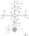
- the second components are schematically shown in Fig. 4 . They are provided separate from the first components for realizing the vacuum cleaning functionality. They comprise a second electric motor 96, a second turbine 98 actuated by the second electric motor 96 in order to create the second air flow 100, and at least one air filter element 104 through which the second air flow 100 is drawn in order to filter out most of the dust contained in the air of the second air flow.
- a low-pressure or vacuum p_1 created by the first turbine 38 in the dust collecting chamber 22 is much lower than a low-pressure p_2 created by the second turbine 98 on its suction side.
- the second turbine 98 is optimized for creating a large-volume air circulation (flow rate).
- the air purifier comprising the second components can realize a flow rate of more than 500m 3 /hour, preferably a flow rate of 700m 3 /hour or more.
- the motor 96 is provided with electric energy and drives the turbine 98.
- the suction side of the turbine 98 is connected to two rather large inlet ports 106 provided in the case 70.
- the turbine 98 draws a large volume of air from the environment through the inlet ports 106 and conveys the air flow 100 through the filter element 104 and then discards it to the environment again through a rather large outlet port 108 provided in the case 70.
- the outlet port 108 is provided in a recess in the top wall of the cover element 84.
- the recess also forms a handle for carrying the case 70 when detached from the housing 15 of the first part 12 of the vacuum cleaner 10.
- the number, form and arrangement of the inlet and outlet ports 106, 108 may vary from what is shown in Figs. 1 to 3 .
- the dust-laden air 110 from the environment surrounding the vacuum cleaner 10 and being sucked into the inlet ports 106 has dust and small particles floating therein. These dust and small particles are mainly caused by the intended use of the power tool attached to the socket 68 and to the suction opening 44 of the hose or tube 26 of the vacuum cleaner 10 or by any other dirty or heavy work performed near the vacuum cleaner 10.
- the purified air 112 discarded to the environment through the outlet port 108 is essentially free of dust or particles because they have been discarded on the input side of the filter element 104.
- the air purifier filters 95% to 98% of the dust and particles out of the dust-laden air 110. All of the components shown in Fig. 4 are arranged in the case 70.
- the second electric motor 96 is provided with electric energy reaching the first part 12 of the vacuum cleaner 10 through the electric cord 19.
- the external housing 70 or case of the second part 14 being separate from the housing 15 of the first part 12 it is necessary to transmit electric energy from the first part 12 of the vacuum cleaner 10 to the second components located in the case 70.
- the top of the first part 12 of the vacuum cleaner 10 and the bottom of the stackable case 70 are provided with electric energy transmitting means in order to transmit electric energy from the first part 12 of the vacuum cleaner 10 to the second electric motor 96 arranged in the stackable case 70.
- the electric energy transmitting means automatically enter into a mutual energy transmitting state, in which electric energy can be transmitted from the first part 12 of the vacuum cleaner 10 to the second electric motor 96.
- the electric energy transmitting means for transmitting electric energy may be designed as a plug and socket combination (not shown) at respective positions in the bottom wall of the case 70 and the top wall of the housing 15 of the first part 12 of the vacuum cleaner 10.
- the electric energy transmitting means make use of any type of wireless power transmission technique.
- power is transferred by magnetic fields using inductive coupling between coils of wire, or by electric fields using capacitive coupling between metal electrodes.
- appropriate coils of wire 114, 116 are provided for realizing an inductive coupling for the wireless power transmission.
- the electric energy comes from the mains socket to the control unit 64 via the electric cord 19 (see Fig. 5 ). From there it is transmitted to the coil 116, from which it is transmitted inductively to the coil 114 (see Fig. 4 ) located at the bottom of the case 70 at a position corresponding to the position of the coil 116 at the top of the housing 15 of the first part 12 of the vacuum cleaner 10, when the case 70 is secured to the top of the housing 15.
- the electric energy received by the coil 114 is then used for operating the second electric motor 96.
- a separate control unit 124 for controlling operation of the second motor 96 may be provided.
- the vacuum cleaner 10 comprises at least one rechargeable battery 118 and/or 118' adapted for supplying the second electric motor 96 of the air purifier with electric energy when the plug 19a of the electric cord 19 of the vacuum cleaner 10 is disconnected from the mains socket.
- the battery may be arranged in the first part 12 of the vacuum cleaner 10, in particular in the cover element 18 (battery 118' in Fig. 5 ).
- the battery is arranged in the second part 14, in particular in the stackable case 70 (battery 118 in Fig. 4 ).
- the battery 118, 118' is charged according to a predefined charging process or scheme when the plug 19a of the electric cord 19 of the vacuum cleaner 10 is connected to a mains socket.
- the battery 118, 118' can take over the energy supply of the second electric motor 96 of the air purifier at least when the plug 19a is detached from the mains socket. It is even possible that the second electric motor 96 is exclusively operated through the battery 118, 118'. Operation of the second electric motor 96 by means of the battery 118, 118' is in particular possible because the electric motor 96, other than the first electric motor 40 for realizing the vacuum cleaning functionality, has a rather low power consumption (in the range of several 10 W, e.g. 30 W to 100 W) .
- the electric energy supplied by the battery 118' will have to be transmitted to the second electric motor 96 through the electric energy transmitting means as described above. In that case the battery 118' can be directly charged by electric current arriving at the control unit 64 through the electric cord 19. In the other case, when the battery 118 is located in the second part 14 of the vacuum cleaner 10, in particular in the case 70, the electric energy supplied by the battery 118 can be directly transmitted to the second electric motor 96 through internal cables or the like. However, in that case the electric current arriving at the control unit 64 through the electric cord 19 has to be transmitted through the electric energy transmitting means, as described above, for charging the battery 118.
- the second electric motor 96 is automatically activated upon activation of the first electric motor 40 of the vacuum cleaner.
- An appropriate control of the second electric motor 96 can be achieved by the control unit 124 possibly in combination with the control unit 64.
- the second electric motor 96 is automatically deactivated after a preset time delay after deactivation of the first electric motor 40.
- the second motor 96 runs longer than the first motor 40 (time delay > 0 sec) in order to purify the dust-laden air surrounding the vacuum cleaner 10 and to filter dust and small particles out of the air flow 100.
- the vacuum cleaner 10 comprises a timer switch 120 adapted for automatically activating and deactivating the second electric motor 96 at preset points in time.
- the timer switch 120 may be part of the second part 14 of the vacuum cleaner 10. However, preferably it is located in the cover element 18 of the first part 12 of the vacuum cleaner 10 next or near to the control dial 66 for controlling operation of the first electric motor 40.
- the points in time for activating and deactivating the air purifier may be manually set by a user or worker, for example when leaving the construction site or the professional workshop or garage after work.
- the timer switch 120 may be of a mechanical type. If it is of an electrical type, it may be provided with electric energy by means of the electric cord 19 plugged into the mains socket or by the battery 118, 118' forming part of the vacuum cleaner 10.
- the vacuum cleaner 10 comprises a particle sensor 122 which is in direct contact with the surroundings (i.e. the environment) of the vacuum cleaner 10 and adapted for measuring the number of particles in a given volume of dust-laden air surrounding the vacuum cleaner 10 and for automatically activating the second electric motor 96 of the air purifier when the measured number of particles exceeds a preset first threshold value and for automatically deactivating the second electric motor 96 when the measured number of particles falls below a preset second threshold value.
- the first and second threshold values for the number of particles in a given volume may be the same.
- the second threshold value is smaller than the first threshold value, thereby providing for some kind of hysteresis.
- the air purifier located in the case 70 comprises its own control unit 124 for controlling operation of the second motor 96 and/or the charging process of the battery 118.
- the air purifier makes use of the control functionalities provided by the control unit 64 of the first part 12 of the vacuum cleaner 10.
- the control functionalities of the control unit 64 would have to be expanded in order for the control unit 64 to be able to control the operation of the second motor 96 and/or the charging process of the battery 118, too. This can be achieved by installing an appropriate computer program which can be executed on a processor of the control unit 64.
- a wireless data transmission connection between the first part 12 and the second part 14 of the vacuum cleaner 10 would have to be provided, too, in order to transmit control signals from the control unit 64 to the second components located in the case 70. It would be possible to use the two wire coils 114, 116 for establishing the wireless data transmission connection.
- FIG. 6 A further embodiment of the present invention is shown in Fig. 6 .
- the two parts 12, 14 are actually one single common part resulting in the vacuum cleaner 10 having only a single housing 15 in which the first components (see Fig. 5 ) for realizing the vacuum cleaning functionality as well as the second components (see Fig. 4 ) for realizing the air purifying functionality are arranged.
- the housing 15 comprises a base element 16 and a cover element 18.
- the first components as well as the second components are preferably all arranged in the cover element 18.
- the cover element 18 may be designed larger than in conventional vacuum cleaners in order to additionally accommodate the second components for realizing the air purifying functionality therein.
- the vacuum cleaner 10 comprises a wireless interface 126 (see Figs. 1 , 5 and 6 ) adapted for establishing a wireless connection 134 with a mobile device 128 (see Fig. 6 ) and control means adapted for permitting control of the first electric motor 40 and/or of the second electric motor 96 by means of the mobile device 128.
- the control means may be realized in the control unit 64 and/or in the control unit 124 or separately from the control units 64, 124. If realized in one or both of the control units 64, 124 the functionality of the control units 64, 124 has to be expanded in order to allow control of the first electric motor 40 and/or of the second electric motor 96 by means of the mobile device 128.
- a computer program (so-called application or App) to be executed by a processor of the mobile device 128 is provided on the mobile device 128.
- the computer program is adapted for establishing the wireless connection 134 between the wireless interface 126 and the mobile device 128 and to send appropriate control commands to the vacuum cleaner 10 in order to provide for control of the first electric motor 40 and/or of the second electric motor 96 by means of the mobile device 128 via the established wireless connection 134.
- the mobile device 128 may have a screen 130 allowing a user or worker to enter desired control commands for the vacuum cleaner 10 by means of a control window 132 displayed on the screen 130.
- control commands may also be input by the user or worker by means of a keypad or the like provided in the mobile device 128.
- Controlling of the vacuum cleaner 10 by means of the mobile device 128 may comprise one or more of the following actions: turning on/off the first electric motor 40 and/or the second electric motor 96, setting the speed of the motors 40, 96, and setting values for the timer switch 120 or threshold values for the particle sensor 122.
- the established wireless connection 134 between the wireless interface 126 of the vacuum cleaner 10 and the mobile device 128 may be used for a wireless data transmission from the vacuum cleaner 10 to the mobile device 128 for transmitting operation parameters and data regarding the first components and/or the second components to the mobile device 128 for presentation on the screen 130.
- the data may be displayed in a special part of the screen 130, e.g. an information window 136.
- the display on the screen 130 does not necessarily have to be split up into control window 132 and information window 136. Instead it could be possible to switch between these two windows 132, 136 by means of a pulldown menu making part of the computer program or simply by swiping over the screen 130.
- Information or data to be displayed on the screen 130 may comprise the current on/off status of the first electric motor 40 and/or the second electric motor 96, current speed settings of the motors 40, 96, current clogging status of the filter elements 34, 104, estimated future time of replacement of the filter elements 34, 104, current setting values of the timer switch 120 or of the threshold values for the particle sensor 122, and current fill level of the dust collection chamber 22.
- the mobile device 128 is one of a smart phone, a tablet computer and a palm computer.
- the wireless interface 126 is adapted for realizing a Bluetooth-, a WiFi-, a NFC- and/or a telecommunication connection (e.g. GSM, EDGE, UMTS, LTE or any other standard known at present or to be realized in future) with the mobile device 128.
- a telecommunication connection e.g. GSM, EDGE, UMTS, LTE or any other standard known at present or to be realized in future
Landscapes
- Chemical & Material Sciences (AREA)
- Chemical Kinetics & Catalysis (AREA)
- Engineering & Computer Science (AREA)
- Mechanical Engineering (AREA)
- Electric Suction Cleaners (AREA)
Description
- The present invention refers to a vacuum cleaner, in particular a mobile vacuum cleaner which can be moved to its destination of use or working environment on wheels or a trolley. The vacuum cleaner may be used in a household or an office building for regular cleaning purposes, in a private or professional workshop or garage, on a construction site or the like. The vacuum cleaner is adapted to draw in dry dust, small particles, small pieces of debris or the like, as well as liquids.
- In the realm of the present invention the term 'vacuum cleaner' is not limited to mobile vacuum cleaners for use in households, professional workshops, garages or on construction sites. It also comprises so-called 'safety dust extractors' comprising a suction hose which is connected to a dust self-extracting channel of a power tool, like a sander or a grinder, in order to draw in dust and other small particles generated during an intended use of the power tool on the working surface.
- The vacuum cleaner comprises a housing with first components arranged therein which interoperate with one another in order to realize a first air flow for a vacuum cleaning functionality. The first components comprise a first electric motor and a first turbine actuated by the first electric motor in order to create the first air flow and a low-pressure or vacuum in a dust collecting chamber of the vacuum cleaner. The dust collecting chamber is provided with an inlet opening in order to such in dust and small particles into the dust collecting chamber. Usually a suction hose or tube having a suction opening at its distal end is connected to the inlet opening. The hose or tube may be used for cleaning small areas of a working space, e.g. a floor or a working bench. The hose may also be connected to a dust self-extracting channel of a power tool, like a sander or a grinder. Due to the first air flow created by the turbine a high-speed but low-volume air flow is generated in the hose or tube, creating a strong airstream which carries away dust and small particles laying on the floor or from the working space of the power tool.
- The air flow with the dust and particles is sucked into the dust collecting chamber, where the larger and heavier particles fall to the bottom. The air flow is then drawn through at least one filter element which filters the remaining smaller particles out of the air flow. Then the air flow runs through the turbine. After passing through the turbine the air is discarded into the environment through appropriate air outlet openings provided in the housing of the vacuum cleaner. The vacuum cleaner may be provided with a self-cleaning or reverse-flushing function of the at least one filter element. Preferably, the self-cleaning function is occasionally automatically activated either when a desired low-pressure value in the dust collecting chamber can no longer be reached (that is when the pressure in the chamber exceeds a threshold value) or regularly from time to time.
- Dust, powder and small particles can be so small that they float in the air and from there may be inhaled and reach the bronchia, where they can cause considerable damage. Air purifiers can filter dust, powder and small particles floating in the air thereby avoiding health threats for people working in such environments with dust-laden air. Air purifiers for filtering large volumes of air and for removing dust and small particles floating in the air within a given volume, e.g. a room or an almost closed space, are well known in the art. In contrast to vacuum cleaners which are activated occasionally, air purifiers are usually provided for long term use. Therefore, their motors have a smaller power (e.g. 20 to 300 W) than those of vacuum cleaners (usually more than 1.000 W). Furthermore, air purifiers are not adapted to generate a very low low-pressure (i.e. a large vacuum) in a chamber or the like but are instead optimized for realizing a large-volume air circulation (up to 1.000 m3/hour). An example for such an air purifier is the Aircleaner AC700 from Klop Innovations, Hermesweg 11A, 4051 BV Ochten, NL. This air purifier circulates an air volume of up to 700 m3/hour. The known air purifiers are stand-alone solutions. When used in professional environments, for example in a professional workshop or garage or on a construction site, they often are in the way, get tripped over or damaged. In order to avoid this, the known air purifier is made of high quality components and has a rugged housing made of Styrofoam. This makes the known air purifier very bulky and expensive.
- Furthermore, a vacuum cleaner named HYLA EST is known in the art, which is manufactured and sold by Hyla Germany GmbH, Hornbergstraße 35, 70794 Filderstadt, DE. This vacuum cleaner claims to have an air purifying functionality integrated therein. Basically, it is just a conventional vacuum cleaner which is provided with a rather efficient hydraulic filtering system for filtering the sucked air before it is discarded into the environment. The vacuum cleaner has only one motor which serves for realizing the vacuum cleaning functionality as well as the air purifying functionality. Despite the fact that the vacuum cleaner can be operated in a special air purifying mode, it still remains a compromise. In the air purifying mode the power consumption is relatively high (the same as in the vacuum cleaning mode because the same motor is used) and the circulated air volume is relatively small (150 m3/hour). Compared to conventional air purifiers the efficiency of the air purifying functionality of this known vacuum cleaner is rather poor. In particular the air purifying performance is limited due to the fact that regular vacuum cleaner components, optimized for vacuum cleaning, are used for trying to achieve the air purifying functionality. Further, this vacuum cleaner is not intended for professional use, for example in a professional workshop or garage or on a construction site. It is technically too sophisticated and too weak to be used in a professional environment. Both the vacuum cleaning performance as well as the air purifying performance is not sufficient for professional use. Another disadvantage is the fact that the air purifying functionality cannot be used contemporarily with the vacuum cleaning functionality. Furthermore, after operation of this vacuum cleaner the water from the hydraulic filtering system comprises particles of various compositions. This water cannot simply be flushed down the drain but has to be disposed of in an environmentally responsible way which is cumbersome, time-consuming and expensive.
- Further prior-art vacuum cleaners are disclosed by
JP 2004 135992 A KR 100 812 285 B1EP 3 127 462 A1 andWO 2016/008860 A1 . - Based on the above, it is an object of the present invention to provide for an easy, safe, efficient and economic air purifying functionality, in particular for use in a rough professional environment, for example in a professional workshop or garage or on a construction site. This object is solved by a vacuum cleaner with the features of claim 1. Starting from the vacuum cleaner of the above identified kind, it is suggested that the vacuum cleaner further comprises second components separate from the first components and the second components interoperating with one another in order to realize a second air flow for a purifying functionality of dust-laden air surrounding the vacuum cleaner. The second components comprise a second electric motor, a second turbine actuated by the second electric motor in order to create the second air flow, and at least one air filter element through which the second air flow is drawn in order to filter out most of the dust contained in the air of the second air flow. The second components are adapted to circulate a larger volume of air per time unit than the first components. They are adapted for long-term activation, i.e. operated continuously for several hours. A low-pressure or vacuum created by the first turbine in the dust collecting chamber is much lower than a low-pressure created by the second turbine on its suction side (hence, the first turbine creates a much larger depression in the vacuum chamber than the depression created by the second turbine).
- The main object of the first components is to realize the functionality of a vacuum cleaner and suck in dust, dirt and small particles discarded and laying on a surface, e.g. the floor, a worktop or the like, into a dust collection chamber. In the case of a safety dust extractor the first components serve for drawing in dust and other small particles (e.g. abrasive dust, residual dried abrasive liquid or paste, sawdust, drill dust, swarf or the like) generated during an intended use of the power tool. The vacuum cleaner sucks in dust, dirt and small particles from where they are laying around or where they are created. The first air flow generated by the first components in a tube or hose is rather large (e.g. around 20 m/s or higher). The volume of circulated air per time unit is rather small (e.g. around 150 m3/h).
- The main object of the second components interoperating with each other is to purify a volume of air surrounding the vacuum cleaner. The speed of the second air flow generated by the second components through the air filter element(s) is rather small (e.g. around 0,5 m/s or lower). The volume of circulated air per time unit is rather large (e.g. up to around 1000 m3/h). The second components can be operated separately from the first components.
- The vacuum cleaner according to the present invention has the advantage that it cannot only fulfil a vacuum cleaning functionality in a rough professional environment, but also an efficient and effective air purifying functionality. This is achieved by integrating separate second components into the vacuum cleaner which provide for the air purifying functionality. These second components can be optimized for the air purifying functionality without having to consider the vacuum cleaning functionality, because this is performed exclusively by the first components. Further, both functionalities can be performed contemporarily.
- The integration of an air purifying functionality into a vacuum cleaner is particularly advantageous when the vacuum cleaner is used in rough environments, such as a professional workshop or garage, a shipyard, a hangar, a construction site or the like. For example, when sanding or polishing a vehicle body, a hull of a boat or an airplane, a large amount of dust and small debris particles is generated and spread in the air, despite the fact that the sander or grinder used may be attached to a vacuum cleaner for removing some of the dust and small particles from the working area and for collecting it in the dust collecting chamber of the vacuum cleaner. Similarly on a construction site, when certain work is performed, for example when slots for electric cables and hydraulic pipes are milled into stone or concrete walls, a large amount of dust and small debris particles is generated and spread in the air. The dust and small particles float in the air and are a health threat for people present near the working area which inhale the dust-laden air. With the present invention not only can the vacuum cleaner be attached to the sander or grinder and can it be used for removing dust and small particles from the working area and for collecting it in the dust collecting chamber of the vacuum cleaner, but additionally the separate air purifier integrated into the vacuum cleaner can perform a highly efficient air purifying functionality for further reducing the number of small particles in the air. The air purifying functionality can be realized any time before, during and after the use of the vacuum cleaner or of the sander/ grinder, respectively.
- According to the invention, the second components are arranged in an external housing or case separate from the housing containing the first components but releasably attached to the housing containing the first components. This embodiment has the advantage that the air purifier forms an integral part of the vacuum cleaner when attached to the housing containing the first components. It is in particular suggested that the external housing or case containing the second components is a stackable case which can be releasably attached to the top of the housing containing the first components, like a case known from
WO 2016/ 008 860 A1 . - In that case it is suggested that the top of the housing containing the first components and the bottom of the external housing or case containing the second components are provided with electric energy transmitting means in order to transmit electric energy from the first components to the second components (e.g. the second electric motor, a control unit) arranged in the external housing or case. Furthermore, means for transmitting control signals between the first and second components could also be provided in the housing containing the first components and the external housing or case containing the second components. Upon positioning or attachment, respectively, of the external housing or case containing the second components to the top of the housing containing the first components the electric energy transmitting means automatically enter into a mutual energy transmitting state, in which electric energy can be transmitted from the first components to the second components.
- For example, the electric energy transmitting means for transmitting electric energy from the first components to the second components may be designed as a plug and socket combination at respective positions in the bottom of the external housing or case containing the second components and in the top of the housing containing the first components. Further, it would be possible that the electric energy transmitting means make use of any type of wireless power transmission technique. In so-called near field or non-radiative techniques, power is transferred by magnetic fields using inductive coupling between coils of wire, or by electric fields using capacitive coupling between metal electrodes. To this end the bottom of the external housing or case containing the second components and the top of the housing containing the first components may be provided with appropriate coils of wire, metal electrodes or the like for realizing the respective wireless power transmission technique.
- According to the invention, the external housing or case containing the second components is provided with a separate electric cord with a plug for connection to a mains socket, in order to provide the second components with electric energy. Yet another possibility would be to provide a rechargeable or exchangeable battery in the external housing or case. The battery could be automatically charged when the external housing or case containing the second components is placed on and secured on top of the housing containing the first components. Both embodiments have the advantage that the air purifier could also be operated when detached from the housing containing the first components.
- There are many different possibilities for activating and/or deactivating the second electric motor of the air purifier. For instance, it is suggested that the second electric motor is automatically activated upon activation of the first electric motor of the vacuum cleaner. By doing so no separate activation of the air purifier is necessary. This greatly facilitates the use of the air purifier and assures clean and purified air near the working area during work. This is in particular advantageous for inexperienced users or workers who have not used the vacuum cleaner according to the invention with the combined vacuum cleaning and air purifying functionalities before because they might forget to separately activate the air purifier when starting work.
- Further, it is suggested that the second electric motor is automatically deactivated after a preset time delay after deactivation of the first electric motor. The time delay starts after deactivation of the vacuum cleaning functionality and may be preset by a user or worker to any desired time duration. It may even be set to zero (time delay = 0 sec) in order to turn off the second motor contemporarily with the first motor. However, it is advantageous that the second motor runs longer than the first motor (time delay > 0 sec) in order to purify the air and filter floating dust and particles out of the air surrounding the vacuum cleaner, the dust and particles resulting from the some kind of work previously performed at a construction site or a professional workshop or garage. Purifying the air (i.e. extracting dust and particles from the dust-laden air) surrounding the vacuum cleaner may take up to several hours (e.g. time delay = appr. 1 ... 12 hours). The time it takes for purifying dust-laden air depends on a number of factors, comprising the concentration of dust and particles in the dust-laden air at the beginning of the purification process, the size of the dust and particles, the type and size of the mounted filters of the air purifier, the efficiency of the air purifier (max. volume (e.g. m3) of dust-laden air the air purifier is able to circulate per time unit (e.g. hour))
- Furthermore, it is suggested that the vacuum cleaner comprises a timer switch adapted for automatically activating and deactivating the second electric motor at preset points in time. The points in time for activating and deactivating the air purifier may be manually preset by a user or worker, for example when leaving the construction site or the professional workshop or garage after work. To this end an appropriate input device for manually setting the points in time by a user are provided in the housing of the vacuum cleaner. It could also be possible to set the points in time by means of a mobile device, for example a smart phone, if the mobile device is in an appropriate wireless data communication connection with the vacuum cleaner. The timer switch may be of a mechanical type. If it is of an electrical type, it may be provided with electric energy by means of the electric cord plugged into the mains socket, or by a battery making part of the vacuum cleaner.
- Finally, it is suggested that the vacuum cleaner comprises a particle sensor which is in contact with the surroundings (i.e. the environment) of the vacuum cleaner and adapted for measuring the number of (dust and small debris) particles floating in a given volume of dust-laden air surrounding the vacuum cleaner and for automatically activating the second electric motor of the air purifier when the measured number of particles exceeds a preset first threshold value and automatically deactivating the second electric motor when the number of particles falls below a preset second threshold value. The first and second threshold values for the number of particles in a given volume may be the same. Preferably, the second threshold value is smaller than the first threshold value, thereby providing some kind of hysteresis. The first and second threshold values may be preset by the manufacturer of the vacuum cleaner and stored in a storing device of a control unit of the vacuum cleaner. Alternatively, they may be set by a user or worker to desired values.
- According to yet another preferred embodiment of the invention it is suggested that the vacuum cleaner comprises a wireless interface adapted for establishing a wireless connection with a mobile device, in particular a smart phone, and control means adapted for permitting control of the first electric motor of the vacuum cleaner and/or of the second electric motor of the air purifier by means of the mobile device via the established wireless connection. Further, it is suggested that the vacuum cleaner comprises a wireless interface adapted for establishing a wireless connection with a mobile device and data transmission means adapted for transmitting operation parameters and data regarding the first components of the vacuum cleaner and/or the second components of the air purifier to the mobile device via the established wireless connection for presentation on a screen of the mobile device. In that case, there is an appropriate computer program (so-called application or App) running on the mobile device for generating and transmitting control commands to the control means and/or for receiving information on the current operational status of the vacuum cleaner and/or the air purifier from the vacuum cleaner. The operation parameters could comprise, for example, information regarding the filling level of the dust collection chamber, or information when the dust collection chamber must be or will probably have to be emptied. The operation parameters may also comprise information regarding the degree of loading (clogging) of the filter elements of the vacuum cleaner and/or of the air purifier with dust and small debris particles, or information when the filter elements must be or will probably have to be cleaned or replaced.
- The mobile device is preferably one of a smart phone, a tablet computer and a palm computer. The wireless interface is adapted for realizing a Bluetooth-, WiFi-, NFC- and/or telecommunication connection (e.g. GSM, EDGE, UMTS, LTE or any other standard known at present or to be realized in future) with the mobile device.
- Further features and advantages of the present invention are explained in enabling detail hereinafter by making reference to preferred embodiments. It is to be understood that the various features and advantages mentioned in respect to a certain embodiment can also be applied to other embodiments, and that they may be important for the invention also separately. The figures show:
- Fig. 1
- a vacuum cleaner having a vacuum cleaning as well as an air purifying functionality, according to a first preferred embodiment of the present invention;
- Fig. 2
- a stackable case containing components for realizing an air purifying functionality and making integral part of the vacuum cleaner according to
Fig. 1 when attached thereto; - Fig. 3
- the stackable case of
Fig. 2 with its cover element opened; - Fig. 4
- components for realizing the air purifying functionality arranged inside the stackable case of
Figs. 2 and3 ; - Fig. 5
- components for realizing the vacuum cleaning functionality arranged inside an housing of the vacuum cleaner of
Fig. 1 ; and - Fig. 6
- a vacuum cleaner having a vacuum cleaning as well as an air purifying functionality, according to a further preferred embodiment of the present invention.
- In
Fig. 1 a vacuum cleaner according to a first embodiment of the present invention is designated in its entirety withreference sign 10. Thevacuum cleaner 10 has a vacuum cleaning functionality as well as an integrated air purifying functionality, which will be described in more detail hereinafter. - In the embodiment of
Fig. 1 thevacuum cleaner 10 comprises afirst part 12 for realizing the vacuum cleaning functionality and asecond part 14 for realizing the air purifying functionality. The twoparts first part 12 thesecond part 14 forms an integral part of thevacuum cleaner 10. - The
first part 12 comprises an essentially well-known vacuum cleaner, preferably for use in professional workshops or garages, in shipyards, in hangars, in construction sites or the like. Thefirst part 12 comprises ahousing 15 consisting of abase element 16 essentially forming a dust collecting chamber 22 (seeFig. 5 ) in its inside and acover element 18 releasably attached to thebase element 16 by connection means 20, which may be in the form of two lateral clips, straps, shackles or the like. Of course, the connection means 20 may also be located at other positions than those shown inFig. 1 and may be embodied differently than shown inFig. 1 . Thebase element 16 is provided withwheels 17 for moving themobile vacuum cleaner 10 to a desired work position. Thecover element 18 contains first components for realizing the vacuum cleaning functionality. Thefirst part 12, in particular thecover element 18, is provided with anelectric cord 19 having aplug 19a for connection to a mains socket at its distal end. The singleelectric cord 19 serves for proving all electric components of thevacuum cleaner 10 with electric energy. - The first components for realizing the vacuum cleaning functionality are schematically shown in
Fig. 5 . They comprise thedust collecting chamber 22 provided in thebase element 16. Thechamber 22 is open to the top and closed in an airtight manner by thecover element 18. It has aninlet opening 24 to which a suction hose orpipe 26 is connected. InFig. 5 a dashedline 21 separates what is arranged in thecover element 18 from what is arranged in thebase element 16. Thecover element 18 comprises aninlet opening 28 leading from thedust collecting chamber 22 into aninlet chamber 30 and further into anoutlet chamber 32. The twochambers filter element 34. Theoutlet chamber 32 has an outlet opening 36 leading to the suction side of afirst turbine 38 actuated by a firstelectric motor 40. Themotor 40 is provided with electric energy through theelectric cord 19. Acontrol unit 64 may be located between theelectric cord 19 and themotor 40. Thecontrol unit 64 may control operation of themotor 40 depending on user inputs and other operating parameters. - The
turbine 38 creates an air flow 42'" leading to a low-pressure or vacuum in theoutlet chamber 32 and further a low-pressure or vacuum of a first pressure value p_1 in thedust collecting chamber 22. This provokes anair flow 42 through asuction opening 44 located at a distal end of the hose orpipe 26, further leading through thedust collecting chamber 22, theinlet opening 28, theinlet chamber 30, the at least onefilter element 34 and theoutlet chamber 32. Theair flow 42 is fast and strong and carries away dust andsmall particles suction opening 44. Thus, theair flow 42 contains dust, small debris particles and the like which are drawn into thedust collecting chamber 22. When entering thechamber 22 larger andheavier particles 58 fall to the bottom of thechamber 22. Further, when passing through the at least onefilter element 34 the remaining dust andparticles 60 are held back by thefilter element 34 and accumulate on an input side of thefilter element 34. - The air drawn by the
turbine 38 is conveyed into adischarge chamber 46 and eventually discarded into the environment through adischarge opening 48. This is basically the well-known functioning of a conventional vacuum cleaner. - User inputs for controlling the operation of the first
electric motor 40 can be set by means of one or more appropriate control switches and/or control dials 66 located at the front of the cover element 18 (seeFig. 1 ). In this example there is acontrol dial 66 which can be turned to a manual mode (M) for manually activating themotor 40, to an automatic mode (A) for automatically activating themotor 40 or to an off-mode (0), in which themotor 40 is turned off. In each of the activation modes (M, A), the speed of themotor 40 can be varied and preset to a desired value. Anelectric socket 68 is provided at the front of thecover element 18 for receiving a plug of an electric power tool (not shown). The distal end of the hose orpipe 26 with itssuction opening 44 may be connected to a dust self-extraction device of the power tool. In the automatic mode (A) the firstelectric motor 40 is automatically activated upon activation of the power tool connected to thesocket 68. By activating the vacuum cleaner most of the dust created during intended use of the power tool is drawn from the working area and its vicinity into thedust collecting chamber 22. - However, the vacuum cleaner may be equipped with additional functionalities, such as a self-cleaning function of the
filter element 34. To this end thedischarge chamber 46 may be equipped with anoutlet opening 50 leading into theoutlet chamber 32 and theinlet chamber 30 may be equipped with anoutlet opening 52 leading into thedust collecting chamber 22. Furthermore, thedischarge opening 48 may be equipped with avalve 54 for permitting and inhibiting an air flow 42' through theopening 48 for discarding air from thedischarge chamber 46 into the environment. Similarly, theoutlet opening 50 may be provided with avalve 56 for permitting and inhibiting anair flow 42" through theopening 50 and the at least onefilter element 34 into thedust collecting chamber 22. - During normal operation of the vacuum cleaner the
valve 54 is open and thevalve 56 is closed and an air flow 42'" runs through the at least onefilter element 34 in a first direction. In order to initiate a self-cleaning process of the at least onefilter element 34 or of part of thefilter element 34 thefilter element 34 is flushed with clean air taken from the environment or from thedischarge chamber 46 in an opposite direction. In particular, thevalve 54 is closed leading to an increase of pressure in thedischarge chamber 46 because theturbine 38 continues to draw air into thechamber 46. Thevalve 56 is opened thereby generating anabrupt air flow 42" directed into theoutlet chamber 32 and running through thefilter element 34 or part of it in a direction opposite to the air flow 42'" during normal operation of the vacuum cleaner. Thevalves first valve 54 is closed in order to build up a high pressure in thedischarge chamber 46, and thereaftervalve 56 is opened in order to create a particular violentcleaning air flow 42". - As a consequence of the cleaning
air flow 42", the dust and particles 60' are abruptly and violently separated from the input side of thefilter element 34 and collected in thedust collecting chamber 22. During the self-cleaning process theturbine 38 may draw air from the environment and not from theoutlet chamber 32. This may be achieved by means of a further opening into the environment on the suction side of theturbine 38 and a further valve element for opening and closing that opening (not shown). - With other words, the self-cleaning process of the
filter element 34 provides for an cleaningair flow 42" through thefilter element 34 directed opposite to the air flow 42'" during normal operation of the vacuum cleaner. The filter cleaning process is executed only from time to time, either on a user's initiative or regularly at certain points in time or when the pressure difference between theinlet chamber 30 and theoutlet chamber 32 exceeds a predefined threshold value, which is indicative of the degree of clogging of thefilter element 34 with dust andparticles 60. The cleaning process takes only a very short time, max. a few seconds, preferably only the fraction of a second. - In order to be able to maintain the conventional vacuum cleaning functionality during the filter cleaning process, it may be possible to provide for two
separate filter elements 34', 34" or for asingle filter element 34 split into twohalves 34', 34", and to divide theoutlet chamber 32 into twoseparate chambers 32', 32" by means of afacultative partition wall 62 drawn in a dashed line. In that case, the right filter element 34' may still be used for the conventional vacuum cleaning process, whereas theleft filter element 34" is cleaned by reverse flushing with the cleaningair flow 42". Further, appropriate further valves (not shown) may be provided in order to switch the normal operation of the vacuum cleaner to theleft filter element 34" and the cleaning process by reverse flushing to the right filter element 34'. - The
second part 14 of thevacuum cleaner 10 shown inFigs. 1 and2 comprises anexternal housing 70 or case containing the second components for realizing the air purifying functionality. Preferably, theexternal housing 70 is a stackable case which can be releasably attached to the top of thehousing 15 containing the first components, in particular to the top surface of thecover element 18. Advantageously, theexternal housing 70 containing the second components is a case compatible with a stackable case system known, for example, fromWO 2016/ 008 860 A1 . Theexternal housing 70 or case has attachment means at its bottom adapted for attachment to a corresponding attachment system located on the top surface of thehousing 15 of thefirst part 12 of thevacuum cleaner 10. Such cases are well-known in the art and usually serve for storing tools, spare parts, consumables for the tools, etc. Thesecases 70 can be stacked one on top of another and can be secured to one another in their stacked position by quick-fastening means, e.g. latches or turn-lock fasteners. - To this end,
case 70 comprisesprotrusions 72 located inrecesses 74 at the front of thecase 70. Similar recesses and protrusions are provided at the back of thecase 70. Further, similar recesses and protrusions may be provided on the sides of thecase 70, too (not shown). For attaching thecase 70 to the top of thecover element 18, first the protrusions at the back of thecase 70 are inserted into corresponding receivingcavities 76 provided in aback wall 78 on top of thecover element 18. Then thecase 70 is laid on the top surface of thecover element 18 by swivelling it downwards about aswivel axis 79 running through thecavities 76. The top of thehousing 15 containing the first components and the bottom of thecase 70 are designed accordingly, in order to hold thecase 70 in a predefined position on top of thehousing 15 in an x-y-plane (essentially corresponding to the plane of extension of the bottom surface of thecase 70 when it rests on top of the housing 15). Thecase 70 is secured to the top of thehousing 15 in this position by means ofappropriate fastener elements 78, which may comprise latches rotatable about rotation axes 80. Thelatches 78 engage behind theprotrusions 72 located at the front of thecase 70, thereby securing thecase 70 also in a z-direction. The receivingcavities 76 and thefastener elements 78 form the attachment system located on the top of thehousing 15 of thefirst part 12 of thevacuum cleaner 10. Of course, the attachment system of the vacuum cleaner can be embodied in any other way, too, as long as it is compatible with the corresponding attachment means of thecase 70. - The
case 70 comprises abase element 82 and acover element 84. Thecover element 84 is attached to thebase element 82 by means of hinges 85 (seeFig. 3 ) extending along at least part of the back of thecase 70. Hence, thecover element 84 can be opened by swivelling it about arotational axis 86. Thecase 70 is provided with a locking member 88 (turn-lock fastener) located at the front of thecase 70. The lockingmember 88 is rotatably attached to thebase element 82 and can be rotated about arotational axis 90 in order to bring it into three different rotational positions. In a locking position shown inFigs. 1 and2 , the lockingmember 88 locks thecover element 84 in its closed position by entering into engagement with at least oneprotrusion 91 located at the front of thecover element 84 of thecase 70 at a respective position corresponding to the lockingmember 88. A rotation of the lockingmember 88 by 180° brings it into a releasing position in which thecover element 84 can be opened (seeFig. 3 ). In the releasing position the at least oneprotrusion 91 is released. In a further securing position (not shown) located at 90° between the locking position and the releasing position thecover element 84 is secured in its closed position. Additionally, the lockingmember 88 enters into engagement with protrusions of another case located on top of thecase 70, the protrusions of the other case corresponding to protrusions 92 of thecase 70 located at the bottom and the front of the case. Thus, in the securing position the other case is also secured to the top of thecase 70. The lockingmember 88, theprotrusions recess 94 extending at the front of thecase 70. This has the advantage that no parts of thecase 70 protrude its external walls. - The second components are arranged inside the
case 70, in particular inside of thebase element 82. The second components interoperate with one another in order to realize a second air flow for a purifying functionality of dust-laden air surrounding thevacuum cleaner 10, hence for realizing the air purification function. The second components are schematically shown inFig. 4 . They are provided separate from the first components for realizing the vacuum cleaning functionality. They comprise a secondelectric motor 96, asecond turbine 98 actuated by the secondelectric motor 96 in order to create thesecond air flow 100, and at least oneair filter element 104 through which thesecond air flow 100 is drawn in order to filter out most of the dust contained in the air of the second air flow. - A low-pressure or vacuum p_1 created by the
first turbine 38 in thedust collecting chamber 22 is much lower than a low-pressure p_2 created by thesecond turbine 98 on its suction side. Thesecond turbine 98 is optimized for creating a large-volume air circulation (flow rate). In particular, the air purifier comprising the second components can realize a flow rate of more than 500m3/hour, preferably a flow rate of 700m3/hour or more. During operation, themotor 96 is provided with electric energy and drives theturbine 98. In this embodiment the suction side of theturbine 98 is connected to two ratherlarge inlet ports 106 provided in thecase 70. Hence, during operation theturbine 98 draws a large volume of air from the environment through theinlet ports 106 and conveys theair flow 100 through thefilter element 104 and then discards it to the environment again through a ratherlarge outlet port 108 provided in thecase 70. In the shown embodiment theoutlet port 108 is provided in a recess in the top wall of thecover element 84. At the same time the recess also forms a handle for carrying thecase 70 when detached from thehousing 15 of thefirst part 12 of thevacuum cleaner 10. Of course, the number, form and arrangement of the inlet andoutlet ports Figs. 1 to 3 . - The dust-
laden air 110 from the environment surrounding thevacuum cleaner 10 and being sucked into theinlet ports 106 has dust and small particles floating therein. These dust and small particles are mainly caused by the intended use of the power tool attached to thesocket 68 and to thesuction opening 44 of the hose ortube 26 of thevacuum cleaner 10 or by any other dirty or heavy work performed near thevacuum cleaner 10. Thepurified air 112 discarded to the environment through theoutlet port 108 is essentially free of dust or particles because they have been discarded on the input side of thefilter element 104. In particular, the air purifier filters 95% to 98% of the dust and particles out of the dust-laden air 110. All of the components shown inFig. 4 are arranged in thecase 70. - Preferably, the second
electric motor 96 is provided with electric energy reaching thefirst part 12 of thevacuum cleaner 10 through theelectric cord 19. With theexternal housing 70 or case of thesecond part 14 being separate from thehousing 15 of thefirst part 12 it is necessary to transmit electric energy from thefirst part 12 of thevacuum cleaner 10 to the second components located in thecase 70. To this end it is suggested that the top of thefirst part 12 of thevacuum cleaner 10 and the bottom of thestackable case 70 are provided with electric energy transmitting means in order to transmit electric energy from thefirst part 12 of thevacuum cleaner 10 to the secondelectric motor 96 arranged in thestackable case 70. Preferably, upon positioning or attachment, respectively, of thestackable case 70 on top of thehousing 15 of thefirst part 12 of thevacuum cleaner 10 the electric energy transmitting means automatically enter into a mutual energy transmitting state, in which electric energy can be transmitted from thefirst part 12 of thevacuum cleaner 10 to the secondelectric motor 96. - For example, the electric energy transmitting means for transmitting electric energy may be designed as a plug and socket combination (not shown) at respective positions in the bottom wall of the
case 70 and the top wall of thehousing 15 of thefirst part 12 of thevacuum cleaner 10. Preferably, the electric energy transmitting means make use of any type of wireless power transmission technique. In near field or non-radiative techniques, power is transferred by magnetic fields using inductive coupling between coils of wire, or by electric fields using capacitive coupling between metal electrodes. Advantageously, at bottom of thecase 70 and at the top of thehousing 15 of thefirst part 12 of thevacuum cleaner 10 appropriate coils ofwire control unit 64 via the electric cord 19 (seeFig. 5 ). From there it is transmitted to thecoil 116, from which it is transmitted inductively to the coil 114 (seeFig. 4 ) located at the bottom of thecase 70 at a position corresponding to the position of thecoil 116 at the top of thehousing 15 of thefirst part 12 of thevacuum cleaner 10, when thecase 70 is secured to the top of thehousing 15. The electric energy received by thecoil 114 is then used for operating the secondelectric motor 96. Between thecoil 114 and the second electric motor 96 aseparate control unit 124 for controlling operation of thesecond motor 96 may be provided. - Furthermore, it is suggested that the
vacuum cleaner 10 comprises at least onerechargeable battery 118 and/or 118' adapted for supplying the secondelectric motor 96 of the air purifier with electric energy when theplug 19a of theelectric cord 19 of thevacuum cleaner 10 is disconnected from the mains socket. The battery may be arranged in thefirst part 12 of thevacuum cleaner 10, in particular in the cover element 18 (battery 118' inFig. 5 ). Preferably, the battery is arranged in thesecond part 14, in particular in the stackable case 70 (battery 118 inFig. 4 ). Advantageously, thebattery 118, 118' is charged according to a predefined charging process or scheme when theplug 19a of theelectric cord 19 of thevacuum cleaner 10 is connected to a mains socket. To this end, thebattery 118, 118' can take over the energy supply of the secondelectric motor 96 of the air purifier at least when theplug 19a is detached from the mains socket. It is even possible that the secondelectric motor 96 is exclusively operated through thebattery 118, 118'. Operation of the secondelectric motor 96 by means of thebattery 118, 118' is in particular possible because theelectric motor 96, other than the firstelectric motor 40 for realizing the vacuum cleaning functionality, has a rather low power consumption (in the range of several 10 W, e.g. 30 W to 100 W) . - If the battery 118' is located in the
first part 12 of thevacuum cleaner 10, the electric energy supplied by the battery 118' will have to be transmitted to the secondelectric motor 96 through the electric energy transmitting means as described above. In that case the battery 118' can be directly charged by electric current arriving at thecontrol unit 64 through theelectric cord 19. In the other case, when thebattery 118 is located in thesecond part 14 of thevacuum cleaner 10, in particular in thecase 70, the electric energy supplied by thebattery 118 can be directly transmitted to the secondelectric motor 96 through internal cables or the like. However, in that case the electric current arriving at thecontrol unit 64 through theelectric cord 19 has to be transmitted through the electric energy transmitting means, as described above, for charging thebattery 118. - There are many different possibilities for activating and/or deactivating the second
electric motor 96 for realizing the air purifier functionality. For instance, it is suggested that the secondelectric motor 96 is automatically activated upon activation of the firstelectric motor 40 of the vacuum cleaner. An appropriate control of the secondelectric motor 96 can be achieved by thecontrol unit 124 possibly in combination with thecontrol unit 64. - Further, it is possible that the second
electric motor 96 is automatically deactivated after a preset time delay after deactivation of the firstelectric motor 40. The time delay may be set by a user or worker to any desired time duration. It may even be set to zero (time delay = 0 sec) in order to turn off thesecond motor 96 contemporarily with thefirst motor 40. However, it is advantageous that thesecond motor 96 runs longer than the first motor 40 (time delay > 0 sec) in order to purify the dust-laden air surrounding thevacuum cleaner 10 and to filter dust and small particles out of theair flow 100. The dust and small particles floating in the dust-laden air may result from the previous intended use of the power tool connected to thesocket 68 and thesuction opening 44 of the hose ortube 26 or from any other work previously performed near thevacuum cleaner 10. Purifying the dust-laden air may take up to several hours (time delay = x hours, x = 1...12). - Furthermore, it is possible that the
vacuum cleaner 10 comprises atimer switch 120 adapted for automatically activating and deactivating the secondelectric motor 96 at preset points in time. Thetimer switch 120 may be part of thesecond part 14 of thevacuum cleaner 10. However, preferably it is located in thecover element 18 of thefirst part 12 of thevacuum cleaner 10 next or near to thecontrol dial 66 for controlling operation of the firstelectric motor 40. The points in time for activating and deactivating the air purifier may be manually set by a user or worker, for example when leaving the construction site or the professional workshop or garage after work. Thetimer switch 120 may be of a mechanical type. If it is of an electrical type, it may be provided with electric energy by means of theelectric cord 19 plugged into the mains socket or by thebattery 118, 118' forming part of thevacuum cleaner 10. - Finally, it is also possible that the
vacuum cleaner 10 comprises aparticle sensor 122 which is in direct contact with the surroundings (i.e. the environment) of thevacuum cleaner 10 and adapted for measuring the number of particles in a given volume of dust-laden air surrounding thevacuum cleaner 10 and for automatically activating the secondelectric motor 96 of the air purifier when the measured number of particles exceeds a preset first threshold value and for automatically deactivating the secondelectric motor 96 when the measured number of particles falls below a preset second threshold value. The first and second threshold values for the number of particles in a given volume may be the same. Preferably, the second threshold value is smaller than the first threshold value, thereby providing for some kind of hysteresis. - It is possible that the air purifier located in the
case 70 comprises itsown control unit 124 for controlling operation of thesecond motor 96 and/or the charging process of thebattery 118. However, it would also be possible that the air purifier makes use of the control functionalities provided by thecontrol unit 64 of thefirst part 12 of thevacuum cleaner 10. In that case the control functionalities of thecontrol unit 64 would have to be expanded in order for thecontrol unit 64 to be able to control the operation of thesecond motor 96 and/or the charging process of thebattery 118, too. This can be achieved by installing an appropriate computer program which can be executed on a processor of thecontrol unit 64. In that case, a wireless data transmission connection between thefirst part 12 and thesecond part 14 of thevacuum cleaner 10 would have to be provided, too, in order to transmit control signals from thecontrol unit 64 to the second components located in thecase 70. It would be possible to use the twowire coils - A further embodiment of the present invention is shown in
Fig. 6 . Other than in the first embodiment, the twoparts vacuum cleaner 10 having only asingle housing 15 in which the first components (seeFig. 5 ) for realizing the vacuum cleaning functionality as well as the second components (seeFig. 4 ) for realizing the air purifying functionality are arranged. Again, it is preferred that thehousing 15 comprises abase element 16 and acover element 18. The first components as well as the second components are preferably all arranged in thecover element 18. To this end, thecover element 18 may be designed larger than in conventional vacuum cleaners in order to additionally accommodate the second components for realizing the air purifying functionality therein. - Further, it is suggested that the
vacuum cleaner 10 comprises a wireless interface 126 (seeFigs. 1 ,5 and6 ) adapted for establishing awireless connection 134 with a mobile device 128 (seeFig. 6 ) and control means adapted for permitting control of the firstelectric motor 40 and/or of the secondelectric motor 96 by means of themobile device 128. The control means may be realized in thecontrol unit 64 and/or in thecontrol unit 124 or separately from thecontrol units control units control units electric motor 40 and/or of the secondelectric motor 96 by means of themobile device 128. This can be achieved by installing an appropriate computer program to be executed by a processor of thecontrol unit electric motor 40 and/or of the secondelectric motor 96 by means of themobile device 128, when running on the processor. - On the other hand, a computer program (so-called application or App) to be executed by a processor of the
mobile device 128 is provided on themobile device 128. The computer program is adapted for establishing thewireless connection 134 between thewireless interface 126 and themobile device 128 and to send appropriate control commands to thevacuum cleaner 10 in order to provide for control of the firstelectric motor 40 and/or of the secondelectric motor 96 by means of themobile device 128 via the establishedwireless connection 134. To this end, themobile device 128 may have ascreen 130 allowing a user or worker to enter desired control commands for thevacuum cleaner 10 by means of acontrol window 132 displayed on thescreen 130. Alternatively, the control commands may also be input by the user or worker by means of a keypad or the like provided in themobile device 128. Controlling of thevacuum cleaner 10 by means of themobile device 128 may comprise one or more of the following actions: turning on/off the firstelectric motor 40 and/or the secondelectric motor 96, setting the speed of themotors timer switch 120 or threshold values for theparticle sensor 122. - Additionally, the established
wireless connection 134 between thewireless interface 126 of thevacuum cleaner 10 and themobile device 128 may be used for a wireless data transmission from thevacuum cleaner 10 to themobile device 128 for transmitting operation parameters and data regarding the first components and/or the second components to themobile device 128 for presentation on thescreen 130. In particular, the data may be displayed in a special part of thescreen 130, e.g. aninformation window 136. Of course, the display on thescreen 130 does not necessarily have to be split up intocontrol window 132 andinformation window 136. Instead it could be possible to switch between these twowindows screen 130. Information or data to be displayed on thescreen 130 may comprise the current on/off status of the firstelectric motor 40 and/or the secondelectric motor 96, current speed settings of themotors filter elements filter elements timer switch 120 or of the threshold values for theparticle sensor 122, and current fill level of thedust collection chamber 22. - It is in particular suggested that the
mobile device 128 is one of a smart phone, a tablet computer and a palm computer. Thewireless interface 126 is adapted for realizing a Bluetooth-, a WiFi-, a NFC- and/or a telecommunication connection (e.g. GSM, EDGE, UMTS, LTE or any other standard known at present or to be realized in future) with themobile device 128.
Claims (11)
- Vacuum cleaner (10) comprising a housing (15) with first components arranged therein which interoperate with one another in order to realize a first air flow (42‴) for a vacuum cleaning functionality, the first components comprising a first electric motor (40) and a first turbine (38) actuated by the first electric motor (40) in order to create the first air flow (42‴) and a low-pressure or vacuum in a dust collecting chamber (22) of the vacuum cleaner (10) provided with an inlet opening (24) in order to suck in dust and small particles into the dust collecting chamber (22), wherein the vacuum cleaner (10) further comprises second components separate from the first components and the second components interoperating with one another in order to realize a second air flow (100) for a purifying functionality of dust-laden air surrounding the vacuum cleaner (10), the second components comprising a second electric motor (96), a second turbine (98) actuated by the second electric motor (96) in order to create the second air flow (100), and at least one air filter element (104) through which the second air flow (100) is drawn in order to filter out dust and small particles from the second air flow (100), wherein the second components (96, 98, 104) are arranged in an external housing (70) or case separate from the housing (15) containing the first components (38, 40), wherein the external housing (70) or case containing the second components (96, 98, 104) is releasably attached to the housing (15) containing the first components (38, 40),
characterized in that
the external housing (70) or case containing the second components (96, 98, 104) is provided with an electric cord with a plug for connection to a mains socket or with a rechargeable battery (118, 118'), the electric cord or the battery (118, 118') adapted for supplying the second electric motor (96) with electric energy independently from a power supply to the first electric motor (40). - Vacuum cleaner (10) according to claim 1, wherein the external housing (70) or case containing the second components (96, 98, 104) is a stackable case provided with attachment means at its bottom adapted for being releasably attached to a corresponding attachment system located on the top of the housing (15) containing the first components (38, 40).
- Vacuum cleaner (10) according to claim 1 or 2, wherein the second electric motor (96) is automatically activated upon activation of the first electric motor (40).
- Vacuum cleaner (10) according to one of the preceding claims, wherein the second electric motor (96) is automatically deactivated after a pre-set time delay, the time delay starting after deactivation of the first electric motor (40).
- Vacuum cleaner (10) according to one of the preceding claims, wherein the vacuum cleaner (10) comprises a timer switch (120) adapted for automatically activating and deactivating the second electric motor (96) at pre-set points in time.
- Vacuum cleaner (10) according to one of the preceding claims, wherein the vacuum cleaner (10) comprises a particle sensor (122) in contact with the surroundings of the vacuum cleaner (10) and adapted for measuring the concentration of dust and small particles in the dust-laden air surrounding the vacuum cleaner (10) and for automatically activating the second electric motor (96) when the measured concentration exceeds a pre-set first threshold value and/or automatically deactivating the second electric motor (96) when the concentration falls below a pre-set second threshold value.
- Vacuum cleaner (10) according to one of the preceding claims, wherein the vacuum cleaner (10) comprises a rechargeable battery (118, 118') adapted for supplying the second electric motor (96) with electric energy at least when a plug (19a) of an electric cord (19) of the vacuum cleaner (10) is disconnected from a mains socket.
- Vacuum cleaner (10) according to claim 7, wherein the battery (118, 118') is automatically charged according to a predefined charging scheme when the plug (19a) of the electric cord (19) of the vacuum cleaner (10) is connected to a mains socket and an energy transmitting connection is established between the electric cord (19) and the battery (118, 118').
- Vacuum cleaner (10) according to one of the preceding claims, wherein the vacuum cleaner (10) comprises a wireless interface (126) adapted for establishing a wireless connection (134) with a mobile device (128) and control means adapted for permitting control of the first electric motor (40) and/or of the second electric motor (96) by means of the mobile device (128) via the established wireless connection (134).
- Vacuum cleaner (10) according to one of the preceding claims, wherein the vacuum cleaner (10) comprises a wireless interface (126) adapted for establishing a wireless connection (134) with a mobile device (128) and data transmission means adapted for transmitting operation parameters and data regarding the first components (38, 40) and/or the second components (96, 98, 104) to the mobile device (128) via the established wireless connection (134) for presentation on a screen (130) of the mobile device (128).
- Vacuum cleaner (10) according to claim 9 or 10, wherein the mobile device (128) is one of a smart phone, a tablet computer and a palm computer, and wherein the wireless interface (126) is one of a Bluetooth-, a WiFi-, a NFC and/or a mobile telecommunication-interface.
Priority Applications (3)
| Application Number | Priority Date | Filing Date | Title |
|---|---|---|---|
| EP17203154.4A EP3488751B1 (en) | 2017-11-22 | 2017-11-22 | Vacuum cleaner |
| CN201811368301.4A CN109805824B (en) | 2017-11-22 | 2018-11-16 | Vacuum cleaner with a vacuum cleaner head |
| US16/196,191 US10959583B2 (en) | 2017-11-22 | 2018-11-20 | Vacuum cleaner |
Applications Claiming Priority (1)
| Application Number | Priority Date | Filing Date | Title |
|---|---|---|---|
| EP17203154.4A EP3488751B1 (en) | 2017-11-22 | 2017-11-22 | Vacuum cleaner |
Publications (3)
| Publication Number | Publication Date |
|---|---|
| EP3488751A1 EP3488751A1 (en) | 2019-05-29 |
| EP3488751C0 EP3488751C0 (en) | 2023-06-07 |
| EP3488751B1 true EP3488751B1 (en) | 2023-06-07 |
Family
ID=60450527
Family Applications (1)
| Application Number | Title | Priority Date | Filing Date |
|---|---|---|---|
| EP17203154.4A Active EP3488751B1 (en) | 2017-11-22 | 2017-11-22 | Vacuum cleaner |
Country Status (3)
| Country | Link |
|---|---|
| US (1) | US10959583B2 (en) |
| EP (1) | EP3488751B1 (en) |
| CN (1) | CN109805824B (en) |
Families Citing this family (10)
| Publication number | Priority date | Publication date | Assignee | Title |
|---|---|---|---|---|
| WO2018099488A1 (en) * | 2016-12-01 | 2018-06-07 | 天佑电器(苏州)有限公司 | Dust collector and self-cleaning method for filter thereof |
| EP3420874A1 (en) * | 2017-06-29 | 2019-01-02 | HILTI Aktiengesellschaft | Filter cleaning |
| DE102019121373B4 (en) * | 2019-08-07 | 2022-03-10 | Netzsch Trockenmahltechnik Gmbh | SEPARATORS WITH PARTIAL FILTRATION |
| EP3804595B1 (en) * | 2019-10-10 | 2022-10-05 | Luca Valentini | Vacuum cleaning device with at least two motors |
| CN115297757B (en) * | 2020-01-06 | 2024-07-19 | 创科地板护理技术有限公司 | Cleaning system with full recovery tank shut-off |
| EP3848312A1 (en) * | 2020-01-10 | 2021-07-14 | Hilti Aktiengesellschaft | Device for receiving a suction hose and suction device with a receiving device |
| EP3981310B1 (en) * | 2020-10-06 | 2024-08-21 | Guido Valentini | Electrically operated mobile vacuum cleaner |
| US20220233040A1 (en) * | 2021-01-26 | 2022-07-28 | Xiwang Qi | Dual Function Robotic Cleaning Device |
| US20220282873A1 (en) * | 2021-03-08 | 2022-09-08 | Whirlpool Corporation | Automatic sensing vent hood |
| TWI786673B (en) * | 2021-06-09 | 2022-12-11 | 大象科技股份有限公司 | Suction device and suction force adjustment method thereof |
Family Cites Families (58)
| Publication number | Priority date | Publication date | Assignee | Title |
|---|---|---|---|---|
| US2280495A (en) * | 1939-08-03 | 1942-04-21 | P A Geier Co | Suction cleaner air flow construction |
| US2731194A (en) * | 1953-02-02 | 1956-01-17 | Moss A Kent | Vacuum cleaner blower |
| US3485671A (en) * | 1966-12-19 | 1969-12-23 | Food Products Inc | Method of cleaning air supply systems and ducts |
| US3771294A (en) * | 1970-11-23 | 1973-11-13 | Ronning Eng Co Inc | Negative pressure feeder-separator in closed loop product grind and discharging system |
| US3732667A (en) * | 1971-04-13 | 1973-05-15 | Singer Co | Vacuum cleaner |
| US3842461A (en) * | 1973-05-15 | 1974-10-22 | Walkee Vacuum Services Ltd | Industrial vacuum apparatus |
| US3955236A (en) * | 1974-07-26 | 1976-05-11 | Richard W. Burt, Jr. | Collector system in a vacuum sweeper circuit |
| GB1595975A (en) * | 1977-04-14 | 1981-08-19 | Summers D | Apparatus for separating particles from gases |
| US4201256A (en) * | 1979-01-10 | 1980-05-06 | Andrew Truhan | Sawdust collector |
| US4231133A (en) * | 1979-03-19 | 1980-11-04 | Deep Steam Extraction (1974) Ltd. | Wet vacuum machine |
| US4735639A (en) * | 1986-06-09 | 1988-04-05 | Vacuum America Corporation | Modular industrial vacuum loading apparatus for ingesting and collecting debris and filtering discharged air |
| AU601133B2 (en) * | 1987-10-08 | 1990-08-30 | Sanyo Electric Co., Ltd. | Vacuum cleaner |
| FR2662296B1 (en) * | 1990-05-15 | 1994-06-17 | Cogema | REMOTE SANITATION INSTALLATION, BY DEGRADATION, OF A SURFACE LOCATED IN HOSTILE ENVIRONMENT, WITH RECOVERY AND TREATMENT OF WASTE. |
| US5062868A (en) * | 1990-08-09 | 1991-11-05 | Aaxon Industrial, Inc. | Method and apparatus for unloading mobile vacuum loaders |
| US5231805A (en) * | 1991-07-01 | 1993-08-03 | Sander James P | Surface cleaning and asbestos removal machine |
| JPH08168451A (en) * | 1994-12-19 | 1996-07-02 | Tec Corp | Vacuum cleaner |
| US5716260A (en) * | 1995-02-03 | 1998-02-10 | Ecolab Inc. | Apparatus and method for cleaning and restoring floor surfaces |
| US5560075A (en) * | 1995-02-27 | 1996-10-01 | Jankowski; William C. | Wet or dry vacuum with low center of gravity |
| US5606767A (en) * | 1995-05-19 | 1997-03-04 | Crlenjak; Jack | Vacuum operated dust and debris removal and collection system |
| US6334234B1 (en) * | 1999-01-08 | 2002-01-01 | Fantom Technologies Inc. | Cleaner head for a vacuum cleaner |
| US6381803B1 (en) * | 1999-04-06 | 2002-05-07 | Shop Vac Corporation | Vacuum cleaner |
| US6471751B1 (en) * | 2000-09-11 | 2002-10-29 | Houston Industrial Corporation | Polycyclonic vacuum collectors for virtually non-stop environmental remediation |
| DE10102924C1 (en) * | 2001-01-23 | 2002-06-13 | Pieper Innovationsgmbh | Blasting treatment process for hard surfaces involves applying at least one auxiliary energy pulse to blasting medium |
| ITMI20011154A1 (en) * | 2001-05-31 | 2002-12-01 | Guido Valentini | APPARATUS FOR THE SUCTION OF DUSTY AND SIMILAR MATERIAL |
| US6804857B1 (en) * | 2001-09-20 | 2004-10-19 | M.D. Manufacturing, Inc. | Apparatus for dampening the noise of a vacuum cleaner |
| JP4099709B2 (en) * | 2002-10-21 | 2008-06-11 | 三菱電機株式会社 | Vacuum cleaner with air purification function |
| ITMI20022527A1 (en) * | 2002-11-28 | 2004-05-29 | Guido Valentini | MOBILE UNIT FOR POWERING ELECTRICAL APPLIANCES |
| US6833016B2 (en) * | 2003-03-27 | 2004-12-21 | Oneida Air Systems, Inc | Dust collection system |
| ITMI20030961A1 (en) * | 2003-05-14 | 2004-11-15 | Guido Valentini | MOTORIZED TOOL WITH SUCTION CAPACITY AND DUST COLLECTION. |
| DE602005006055T2 (en) * | 2004-07-16 | 2009-05-14 | Makita Corp., Anjo | Cutting devices with dust collectors |
| CA2522116A1 (en) * | 2004-10-04 | 2006-04-04 | Panasonic Corporation Of North America | Floor cleaning apparatus with wireless control interface |
| KR100555319B1 (en) * | 2004-12-22 | 2006-03-03 | 삼성광주전자 주식회사 | Dust collector for vacuum cleaner and dust collection method using same |
| WO2007022959A2 (en) * | 2005-08-26 | 2007-03-01 | Miele & Cie. Kg | Method for treating dust and devices for carrying out this method |
| ITMI20060815A1 (en) * | 2006-04-24 | 2007-10-25 | Guido Valentini | DUST COLLECTION CONTAINER WITH PALLET ELEMENT FOR MOTORIZED TOOL WITH SUCTION CAPACITY |
| US7282074B1 (en) * | 2006-04-28 | 2007-10-16 | Witter Robert M | Auxiliary dust collection system |
| US7399218B2 (en) * | 2006-06-27 | 2008-07-15 | Witter Robert M | Ride-on floor machine with dust collection system |
| US7550021B2 (en) * | 2006-07-19 | 2009-06-23 | Witter Robert M | Portable cyclonic dust collection system |
| ITCR20060018A1 (en) * | 2006-07-24 | 2008-01-25 | Bertolazzi Marino Pedrazzini | TITLE: VACUUM CLEANER WITH ADDITIONAL FUNCTIONALITY |
| KR100812285B1 (en) * | 2006-11-14 | 2008-03-13 | 주식회사 우리기술 | Air Cleaner Robot Cleaner |
| US20080172146A1 (en) * | 2007-01-12 | 2008-07-17 | Chen-Wei Lin | Robot platform provided with changeable/expandable module |
| US9119511B2 (en) * | 2007-03-02 | 2015-09-01 | Carl L. C. Kah, Jr. | Centrifugal dirt separation configurations for household-type and shop-type vacuum cleaners |
| WO2008109081A1 (en) * | 2007-03-02 | 2008-09-12 | Kah Carl L C Jr | Centrifugal dirt separation configurations for household-type and shop-type vacuum cleaners |
| US7761957B2 (en) * | 2008-02-06 | 2010-07-27 | H-P Products, Inc. | Vacuum canister with dual removable motors |
| EP2087828A1 (en) * | 2008-02-07 | 2009-08-12 | Koninklijke Philips Electronics N.V. | Handgrip assembly for a suction attachment |
| GB0910679D0 (en) * | 2009-06-19 | 2009-08-05 | Numatic Int Ltd | Mobile electrical appliance with cable reeler |
| US8337580B2 (en) * | 2010-09-03 | 2012-12-25 | Manska Wayne E | Debris separator |
| CN110223495A (en) * | 2012-12-18 | 2019-09-10 | 三星电子株式会社 | For the method and apparatus in domestic network system medium-long range control household equipment |
| US10729294B2 (en) * | 2013-02-28 | 2020-08-04 | Omachron Intellectual Property Inc. | Hand carryable surface cleaning apparatus |
| JP6178677B2 (en) * | 2013-09-09 | 2017-08-09 | シャープ株式会社 | Self-propelled electronic device |
| US9107550B2 (en) * | 2013-09-27 | 2015-08-18 | Black & Decker Inc. | Compact vacuum and sander |
| US10293476B2 (en) | 2014-07-12 | 2019-05-21 | Festool Gmbh | Stack arrangement and transport container having bus interfaces |
| EP3009058B1 (en) * | 2014-10-13 | 2021-02-24 | Guido Valentini | Vacuum cleaner pneumatically connected to a power tool, method for controlling operation parameters of such a vacuum cleaner and power tool for pneumatic connection to such a vacuum cleaner |
| DE102014224570A1 (en) * | 2014-12-02 | 2016-06-02 | Robert Bosch Gmbh | Protective device for a machine tool, at least to protect a workpiece surface from overheating |
| WO2016099048A1 (en) * | 2014-12-15 | 2016-06-23 | Samsung Electronics Co., Ltd. | Electronic apparatus and method of controlling group action |
| US11575534B2 (en) * | 2015-02-10 | 2023-02-07 | Universal Electronics Inc. | System and method for aggregating and analyzing the status of a system |
| TW201705889A (en) * | 2015-08-04 | 2017-02-16 | Massif Co Ltd | Self-propelled device with vacuum cleaning and air purifying functions enabling an air purifier positioned on a self-propelled vacuum cleaner to access a power source from the self-propelled vacuum cleaner |
| CN206560406U (en) * | 2016-11-21 | 2017-10-17 | 肇庆学院 | Equipment with air cleaning and floor suction dual-use function |
| JP6798011B2 (en) * | 2017-04-19 | 2020-12-09 | 三菱電機株式会社 | Electric blowers, vacuum cleaners, and hand dryers |
-
2017
- 2017-11-22 EP EP17203154.4A patent/EP3488751B1/en active Active
-
2018
- 2018-11-16 CN CN201811368301.4A patent/CN109805824B/en active Active
- 2018-11-20 US US16/196,191 patent/US10959583B2/en active Active
Also Published As
| Publication number | Publication date |
|---|---|
| EP3488751C0 (en) | 2023-06-07 |
| EP3488751A1 (en) | 2019-05-29 |
| CN109805824B (en) | 2021-11-30 |
| US10959583B2 (en) | 2021-03-30 |
| US20190150683A1 (en) | 2019-05-23 |
| CN109805824A (en) | 2019-05-28 |
Similar Documents
| Publication | Publication Date | Title |
|---|---|---|
| EP3488751B1 (en) | Vacuum cleaner | |
| US20100115726A1 (en) | Handheld vacuum cleaner | |
| TW201633985A (en) | Base station for a vacuum cleaner | |
| DE102011054162A1 (en) | Assembled system of base station and automatic movable cleaning device e.g. household robotic vacuum cleaner, has base station with receptacle that is designed, so that self-positioning of dirt container in receptacle is achieved | |
| EP3419489B1 (en) | Accessory for use with vacuum cleaners | |
| US12185899B1 (en) | Detachable robotic vacuum dustbin | |
| US20120151710A1 (en) | Reverse flow vacuum system | |
| EP3995063B1 (en) | Vacuum cleaner | |
| US20210127938A1 (en) | Accessory for use with vacuum cleaners | |
| EP3525646B1 (en) | Surface cleaning apparatus | |
| EP2783617A1 (en) | Self-propelled vacuum cleaner | |
| CN112933791A (en) | Filter device and power tool device | |
| EP3395770A1 (en) | Mineral water acquisition device | |
| EP3809934B1 (en) | Cleaning appliance | |
| CN209252676U (en) | A kind of hand held cleaner | |
| EP3804595B1 (en) | Vacuum cleaning device with at least two motors | |
| CN209252675U (en) | A kind of hand held cleaner | |
| CN208274535U (en) | Electric tool and its air filtering assembly | |
| CN209186549U (en) | A kind of hand held cleaner | |
| CN216628423U (en) | Host computer and surface cleaning equipment | |
| EP3981310B1 (en) | Electrically operated mobile vacuum cleaner | |
| CN215847643U (en) | Dust collection cleaning device for floor grinding machine | |
| CN115702767A (en) | Host computer and surface cleaning equipment | |
| EP2105079B1 (en) | Vacuum cleaner | |
| CN117731187A (en) | Remote controller for controlling operation state of suction device |
Legal Events
| Date | Code | Title | Description |
|---|---|---|---|
| PUAI | Public reference made under article 153(3) epc to a published international application that has entered the european phase |
Free format text: ORIGINAL CODE: 0009012 |
|
| STAA | Information on the status of an ep patent application or granted ep patent |
Free format text: STATUS: THE APPLICATION HAS BEEN PUBLISHED |
|
| AK | Designated contracting states |
Kind code of ref document: A1 Designated state(s): AL AT BE BG CH CY CZ DE DK EE ES FI FR GB GR HR HU IE IS IT LI LT LU LV MC MK MT NL NO PL PT RO RS SE SI SK SM TR |
|
| AX | Request for extension of the european patent |
Extension state: BA ME |
|
| STAA | Information on the status of an ep patent application or granted ep patent |
Free format text: STATUS: REQUEST FOR EXAMINATION WAS MADE |
|
| 17P | Request for examination filed |
Effective date: 20191129 |
|
| RBV | Designated contracting states (corrected) |
Designated state(s): AL AT BE BG CH CY CZ DE DK EE ES FI FR GB GR HR HU IE IS IT LI LT LU LV MC MK MT NL NO PL PT RO RS SE SI SK SM TR |
|
| GRAP | Despatch of communication of intention to grant a patent |
Free format text: ORIGINAL CODE: EPIDOSNIGR1 |
|
| STAA | Information on the status of an ep patent application or granted ep patent |
Free format text: STATUS: GRANT OF PATENT IS INTENDED |
|
| INTG | Intention to grant announced |
Effective date: 20230110 |
|
| GRAS | Grant fee paid |
Free format text: ORIGINAL CODE: EPIDOSNIGR3 |
|
| GRAA | (expected) grant |
Free format text: ORIGINAL CODE: 0009210 |
|
| STAA | Information on the status of an ep patent application or granted ep patent |
Free format text: STATUS: THE PATENT HAS BEEN GRANTED |
|
| AK | Designated contracting states |
Kind code of ref document: B1 Designated state(s): AL AT BE BG CH CY CZ DE DK EE ES FI FR GB GR HR HU IE IS IT LI LT LU LV MC MK MT NL NO PL PT RO RS SE SI SK SM TR |
|
| REG | Reference to a national code |
Ref country code: GB Ref legal event code: FG4D |
|
| P01 | Opt-out of the competence of the unified patent court (upc) registered |
Effective date: 20230508 |
|
| REG | Reference to a national code |
Ref country code: CH Ref legal event code: EP Ref country code: AT Ref legal event code: REF Ref document number: 1572239 Country of ref document: AT Kind code of ref document: T Effective date: 20230615 |
|
| REG | Reference to a national code |
Ref country code: DE Ref legal event code: R096 Ref document number: 602017069396 Country of ref document: DE |
|
| U01 | Request for unitary effect filed |
Effective date: 20230705 |
|
| U07 | Unitary effect registered |
Designated state(s): AT BE BG DE DK EE FI FR IT LT LU LV MT NL PT SE SI Effective date: 20230714 |
|
| P04 | Withdrawal of opt-out of the competence of the unified patent court (upc) registered |
Effective date: 20230711 |
|
| REG | Reference to a national code |
Ref country code: LT Ref legal event code: MG9D |
|
| PG25 | Lapsed in a contracting state [announced via postgrant information from national office to epo] |
Ref country code: NO Free format text: LAPSE BECAUSE OF FAILURE TO SUBMIT A TRANSLATION OF THE DESCRIPTION OR TO PAY THE FEE WITHIN THE PRESCRIBED TIME-LIMIT Effective date: 20230907 Ref country code: ES Free format text: LAPSE BECAUSE OF FAILURE TO SUBMIT A TRANSLATION OF THE DESCRIPTION OR TO PAY THE FEE WITHIN THE PRESCRIBED TIME-LIMIT Effective date: 20230607 |
|
| PG25 | Lapsed in a contracting state [announced via postgrant information from national office to epo] |
Ref country code: RS Free format text: LAPSE BECAUSE OF FAILURE TO SUBMIT A TRANSLATION OF THE DESCRIPTION OR TO PAY THE FEE WITHIN THE PRESCRIBED TIME-LIMIT Effective date: 20230607 Ref country code: HR Free format text: LAPSE BECAUSE OF FAILURE TO SUBMIT A TRANSLATION OF THE DESCRIPTION OR TO PAY THE FEE WITHIN THE PRESCRIBED TIME-LIMIT Effective date: 20230607 Ref country code: GR Free format text: LAPSE BECAUSE OF FAILURE TO SUBMIT A TRANSLATION OF THE DESCRIPTION OR TO PAY THE FEE WITHIN THE PRESCRIBED TIME-LIMIT Effective date: 20230908 |
|
| U20 | Renewal fee paid [unitary effect] |
Year of fee payment: 7 Effective date: 20231103 |
|
| PG25 | Lapsed in a contracting state [announced via postgrant information from national office to epo] |
Ref country code: SK Free format text: LAPSE BECAUSE OF FAILURE TO SUBMIT A TRANSLATION OF THE DESCRIPTION OR TO PAY THE FEE WITHIN THE PRESCRIBED TIME-LIMIT Effective date: 20230607 |
|
| PG25 | Lapsed in a contracting state [announced via postgrant information from national office to epo] |
Ref country code: IS Free format text: LAPSE BECAUSE OF FAILURE TO SUBMIT A TRANSLATION OF THE DESCRIPTION OR TO PAY THE FEE WITHIN THE PRESCRIBED TIME-LIMIT Effective date: 20231007 |
|
| PG25 | Lapsed in a contracting state [announced via postgrant information from national office to epo] |
Ref country code: SM Free format text: LAPSE BECAUSE OF FAILURE TO SUBMIT A TRANSLATION OF THE DESCRIPTION OR TO PAY THE FEE WITHIN THE PRESCRIBED TIME-LIMIT Effective date: 20230607 Ref country code: SK Free format text: LAPSE BECAUSE OF FAILURE TO SUBMIT A TRANSLATION OF THE DESCRIPTION OR TO PAY THE FEE WITHIN THE PRESCRIBED TIME-LIMIT Effective date: 20230607 Ref country code: RO Free format text: LAPSE BECAUSE OF FAILURE TO SUBMIT A TRANSLATION OF THE DESCRIPTION OR TO PAY THE FEE WITHIN THE PRESCRIBED TIME-LIMIT Effective date: 20230607 Ref country code: IS Free format text: LAPSE BECAUSE OF FAILURE TO SUBMIT A TRANSLATION OF THE DESCRIPTION OR TO PAY THE FEE WITHIN THE PRESCRIBED TIME-LIMIT Effective date: 20231007 Ref country code: CZ Free format text: LAPSE BECAUSE OF FAILURE TO SUBMIT A TRANSLATION OF THE DESCRIPTION OR TO PAY THE FEE WITHIN THE PRESCRIBED TIME-LIMIT Effective date: 20230607 |
|
| PG25 | Lapsed in a contracting state [announced via postgrant information from national office to epo] |
Ref country code: PL Free format text: LAPSE BECAUSE OF FAILURE TO SUBMIT A TRANSLATION OF THE DESCRIPTION OR TO PAY THE FEE WITHIN THE PRESCRIBED TIME-LIMIT Effective date: 20230607 |
|
| REG | Reference to a national code |
Ref country code: DE Ref legal event code: R097 Ref document number: 602017069396 Country of ref document: DE |
|
| PLBE | No opposition filed within time limit |
Free format text: ORIGINAL CODE: 0009261 |
|
| STAA | Information on the status of an ep patent application or granted ep patent |
Free format text: STATUS: NO OPPOSITION FILED WITHIN TIME LIMIT |
|
| 26N | No opposition filed |
Effective date: 20240308 |
|
| REG | Reference to a national code |
Ref country code: CH Ref legal event code: PL |
|
| PG25 | Lapsed in a contracting state [announced via postgrant information from national office to epo] |
Ref country code: MC Free format text: LAPSE BECAUSE OF FAILURE TO SUBMIT A TRANSLATION OF THE DESCRIPTION OR TO PAY THE FEE WITHIN THE PRESCRIBED TIME-LIMIT Effective date: 20230607 |
|
| PG25 | Lapsed in a contracting state [announced via postgrant information from national office to epo] |
Ref country code: CH Free format text: LAPSE BECAUSE OF NON-PAYMENT OF DUE FEES Effective date: 20231130 |
|
| PG25 | Lapsed in a contracting state [announced via postgrant information from national office to epo] |
Ref country code: MC Free format text: LAPSE BECAUSE OF FAILURE TO SUBMIT A TRANSLATION OF THE DESCRIPTION OR TO PAY THE FEE WITHIN THE PRESCRIBED TIME-LIMIT Effective date: 20230607 Ref country code: CH Free format text: LAPSE BECAUSE OF NON-PAYMENT OF DUE FEES Effective date: 20231130 |
|
| REG | Reference to a national code |
Ref country code: IE Ref legal event code: MM4A |
|
| PG25 | Lapsed in a contracting state [announced via postgrant information from national office to epo] |
Ref country code: IE Free format text: LAPSE BECAUSE OF NON-PAYMENT OF DUE FEES Effective date: 20231122 |
|
| PG25 | Lapsed in a contracting state [announced via postgrant information from national office to epo] |
Ref country code: IE Free format text: LAPSE BECAUSE OF NON-PAYMENT OF DUE FEES Effective date: 20231122 |
|
| U20 | Renewal fee paid [unitary effect] |
Year of fee payment: 8 Effective date: 20241119 |
|
| P05 | Withdrawal of opt-out of the competence of the unified patent court (upc) changed |
Free format text: CASE NUMBER: APP_549013/2023 Effective date: 20230714 |
|
| PGFP | Annual fee paid to national office [announced via postgrant information from national office to epo] |
Ref country code: GB Payment date: 20241120 Year of fee payment: 8 |