EP3459502B1 - Implants vertébraux - Google Patents
Implants vertébraux Download PDFInfo
- Publication number
- EP3459502B1 EP3459502B1 EP18195567.5A EP18195567A EP3459502B1 EP 3459502 B1 EP3459502 B1 EP 3459502B1 EP 18195567 A EP18195567 A EP 18195567A EP 3459502 B1 EP3459502 B1 EP 3459502B1
- Authority
- EP
- European Patent Office
- Prior art keywords
- spinal implant
- solid
- porous
- wall
- anterior
- Prior art date
- Legal status (The legal status is an assumption and is not a legal conclusion. Google has not performed a legal analysis and makes no representation as to the accuracy of the status listed.)
- Active
Links
Images


Classifications
-
- A—HUMAN NECESSITIES
- A61—MEDICAL OR VETERINARY SCIENCE; HYGIENE
- A61F—FILTERS IMPLANTABLE INTO BLOOD VESSELS; PROSTHESES; DEVICES PROVIDING PATENCY TO, OR PREVENTING COLLAPSING OF, TUBULAR STRUCTURES OF THE BODY, e.g. STENTS; ORTHOPAEDIC, NURSING OR CONTRACEPTIVE DEVICES; FOMENTATION; TREATMENT OR PROTECTION OF EYES OR EARS; BANDAGES, DRESSINGS OR ABSORBENT PADS; FIRST-AID KITS
- A61F2/00—Filters implantable into blood vessels; Prostheses, i.e. artificial substitutes or replacements for parts of the body; Appliances for connecting them with the body; Devices providing patency to, or preventing collapsing of, tubular structures of the body, e.g. stents
- A61F2/02—Prostheses implantable into the body
- A61F2/30—Joints
- A61F2/44—Joints for the spine, e.g. vertebrae, spinal discs
- A61F2/4455—Joints for the spine, e.g. vertebrae, spinal discs for the fusion of spinal bodies, e.g. intervertebral fusion of adjacent spinal bodies, e.g. fusion cages
- A61F2/447—Joints for the spine, e.g. vertebrae, spinal discs for the fusion of spinal bodies, e.g. intervertebral fusion of adjacent spinal bodies, e.g. fusion cages substantially parallelepipedal, e.g. having a rectangular or trapezoidal cross-section
-
- A—HUMAN NECESSITIES
- A61—MEDICAL OR VETERINARY SCIENCE; HYGIENE
- A61F—FILTERS IMPLANTABLE INTO BLOOD VESSELS; PROSTHESES; DEVICES PROVIDING PATENCY TO, OR PREVENTING COLLAPSING OF, TUBULAR STRUCTURES OF THE BODY, e.g. STENTS; ORTHOPAEDIC, NURSING OR CONTRACEPTIVE DEVICES; FOMENTATION; TREATMENT OR PROTECTION OF EYES OR EARS; BANDAGES, DRESSINGS OR ABSORBENT PADS; FIRST-AID KITS
- A61F2/00—Filters implantable into blood vessels; Prostheses, i.e. artificial substitutes or replacements for parts of the body; Appliances for connecting them with the body; Devices providing patency to, or preventing collapsing of, tubular structures of the body, e.g. stents
- A61F2/02—Prostheses implantable into the body
- A61F2/30—Joints
- A61F2/44—Joints for the spine, e.g. vertebrae, spinal discs
- A61F2/4455—Joints for the spine, e.g. vertebrae, spinal discs for the fusion of spinal bodies, e.g. intervertebral fusion of adjacent spinal bodies, e.g. fusion cages
-
- A—HUMAN NECESSITIES
- A61—MEDICAL OR VETERINARY SCIENCE; HYGIENE
- A61F—FILTERS IMPLANTABLE INTO BLOOD VESSELS; PROSTHESES; DEVICES PROVIDING PATENCY TO, OR PREVENTING COLLAPSING OF, TUBULAR STRUCTURES OF THE BODY, e.g. STENTS; ORTHOPAEDIC, NURSING OR CONTRACEPTIVE DEVICES; FOMENTATION; TREATMENT OR PROTECTION OF EYES OR EARS; BANDAGES, DRESSINGS OR ABSORBENT PADS; FIRST-AID KITS
- A61F2/00—Filters implantable into blood vessels; Prostheses, i.e. artificial substitutes or replacements for parts of the body; Appliances for connecting them with the body; Devices providing patency to, or preventing collapsing of, tubular structures of the body, e.g. stents
- A61F2/02—Prostheses implantable into the body
- A61F2/30—Joints
- A61F2002/30001—Additional features of subject-matter classified in A61F2/28, A61F2/30 and subgroups thereof
- A61F2002/30003—Material related properties of the prosthesis or of a coating on the prosthesis
- A61F2002/30004—Material related properties of the prosthesis or of a coating on the prosthesis the prosthesis being made from materials having different values of a given property at different locations within the same prosthesis
- A61F2002/30011—Material related properties of the prosthesis or of a coating on the prosthesis the prosthesis being made from materials having different values of a given property at different locations within the same prosthesis differing in porosity
-
- A—HUMAN NECESSITIES
- A61—MEDICAL OR VETERINARY SCIENCE; HYGIENE
- A61F—FILTERS IMPLANTABLE INTO BLOOD VESSELS; PROSTHESES; DEVICES PROVIDING PATENCY TO, OR PREVENTING COLLAPSING OF, TUBULAR STRUCTURES OF THE BODY, e.g. STENTS; ORTHOPAEDIC, NURSING OR CONTRACEPTIVE DEVICES; FOMENTATION; TREATMENT OR PROTECTION OF EYES OR EARS; BANDAGES, DRESSINGS OR ABSORBENT PADS; FIRST-AID KITS
- A61F2/00—Filters implantable into blood vessels; Prostheses, i.e. artificial substitutes or replacements for parts of the body; Appliances for connecting them with the body; Devices providing patency to, or preventing collapsing of, tubular structures of the body, e.g. stents
- A61F2/02—Prostheses implantable into the body
- A61F2/30—Joints
- A61F2002/30001—Additional features of subject-matter classified in A61F2/28, A61F2/30 and subgroups thereof
- A61F2002/30316—The prosthesis having different structural features at different locations within the same prosthesis; Connections between prosthetic parts; Special structural features of bone or joint prostheses not otherwise provided for
- A61F2002/30535—Special structural features of bone or joint prostheses not otherwise provided for
- A61F2002/30593—Special structural features of bone or joint prostheses not otherwise provided for hollow
-
- A—HUMAN NECESSITIES
- A61—MEDICAL OR VETERINARY SCIENCE; HYGIENE
- A61F—FILTERS IMPLANTABLE INTO BLOOD VESSELS; PROSTHESES; DEVICES PROVIDING PATENCY TO, OR PREVENTING COLLAPSING OF, TUBULAR STRUCTURES OF THE BODY, e.g. STENTS; ORTHOPAEDIC, NURSING OR CONTRACEPTIVE DEVICES; FOMENTATION; TREATMENT OR PROTECTION OF EYES OR EARS; BANDAGES, DRESSINGS OR ABSORBENT PADS; FIRST-AID KITS
- A61F2/00—Filters implantable into blood vessels; Prostheses, i.e. artificial substitutes or replacements for parts of the body; Appliances for connecting them with the body; Devices providing patency to, or preventing collapsing of, tubular structures of the body, e.g. stents
- A61F2/02—Prostheses implantable into the body
- A61F2/30—Joints
- A61F2/30767—Special external or bone-contacting surface, e.g. coating for improving bone ingrowth
- A61F2/30771—Special external or bone-contacting surface, e.g. coating for improving bone ingrowth applied in original prostheses, e.g. holes or grooves
- A61F2002/30904—Special external or bone-contacting surface, e.g. coating for improving bone ingrowth applied in original prostheses, e.g. holes or grooves serrated profile, i.e. saw-toothed
-
- A—HUMAN NECESSITIES
- A61—MEDICAL OR VETERINARY SCIENCE; HYGIENE
- A61F—FILTERS IMPLANTABLE INTO BLOOD VESSELS; PROSTHESES; DEVICES PROVIDING PATENCY TO, OR PREVENTING COLLAPSING OF, TUBULAR STRUCTURES OF THE BODY, e.g. STENTS; ORTHOPAEDIC, NURSING OR CONTRACEPTIVE DEVICES; FOMENTATION; TREATMENT OR PROTECTION OF EYES OR EARS; BANDAGES, DRESSINGS OR ABSORBENT PADS; FIRST-AID KITS
- A61F2/00—Filters implantable into blood vessels; Prostheses, i.e. artificial substitutes or replacements for parts of the body; Appliances for connecting them with the body; Devices providing patency to, or preventing collapsing of, tubular structures of the body, e.g. stents
- A61F2/02—Prostheses implantable into the body
- A61F2/30—Joints
- A61F2/30767—Special external or bone-contacting surface, e.g. coating for improving bone ingrowth
- A61F2002/3092—Special external or bone-contacting surface, e.g. coating for improving bone ingrowth having an open-celled or open-pored structure
-
- A—HUMAN NECESSITIES
- A61—MEDICAL OR VETERINARY SCIENCE; HYGIENE
- A61F—FILTERS IMPLANTABLE INTO BLOOD VESSELS; PROSTHESES; DEVICES PROVIDING PATENCY TO, OR PREVENTING COLLAPSING OF, TUBULAR STRUCTURES OF THE BODY, e.g. STENTS; ORTHOPAEDIC, NURSING OR CONTRACEPTIVE DEVICES; FOMENTATION; TREATMENT OR PROTECTION OF EYES OR EARS; BANDAGES, DRESSINGS OR ABSORBENT PADS; FIRST-AID KITS
- A61F2/00—Filters implantable into blood vessels; Prostheses, i.e. artificial substitutes or replacements for parts of the body; Appliances for connecting them with the body; Devices providing patency to, or preventing collapsing of, tubular structures of the body, e.g. stents
- A61F2/02—Prostheses implantable into the body
- A61F2/30—Joints
- A61F2/30767—Special external or bone-contacting surface, e.g. coating for improving bone ingrowth
- A61F2002/3093—Special external or bone-contacting surface, e.g. coating for improving bone ingrowth for promoting ingrowth of bone tissue
-
- A—HUMAN NECESSITIES
- A61—MEDICAL OR VETERINARY SCIENCE; HYGIENE
- A61F—FILTERS IMPLANTABLE INTO BLOOD VESSELS; PROSTHESES; DEVICES PROVIDING PATENCY TO, OR PREVENTING COLLAPSING OF, TUBULAR STRUCTURES OF THE BODY, e.g. STENTS; ORTHOPAEDIC, NURSING OR CONTRACEPTIVE DEVICES; FOMENTATION; TREATMENT OR PROTECTION OF EYES OR EARS; BANDAGES, DRESSINGS OR ABSORBENT PADS; FIRST-AID KITS
- A61F2/00—Filters implantable into blood vessels; Prostheses, i.e. artificial substitutes or replacements for parts of the body; Appliances for connecting them with the body; Devices providing patency to, or preventing collapsing of, tubular structures of the body, e.g. stents
- A61F2/02—Prostheses implantable into the body
- A61F2/30—Joints
- A61F2/3094—Designing or manufacturing processes
- A61F2/30942—Designing or manufacturing processes for designing or making customized prostheses, e.g. using templates, CT or NMR scans, finite-element analysis or CAD-CAM techniques
- A61F2002/30962—Designing or manufacturing processes for designing or making customized prostheses, e.g. using templates, CT or NMR scans, finite-element analysis or CAD-CAM techniques using stereolithography
-
- A—HUMAN NECESSITIES
- A61—MEDICAL OR VETERINARY SCIENCE; HYGIENE
- A61F—FILTERS IMPLANTABLE INTO BLOOD VESSELS; PROSTHESES; DEVICES PROVIDING PATENCY TO, OR PREVENTING COLLAPSING OF, TUBULAR STRUCTURES OF THE BODY, e.g. STENTS; ORTHOPAEDIC, NURSING OR CONTRACEPTIVE DEVICES; FOMENTATION; TREATMENT OR PROTECTION OF EYES OR EARS; BANDAGES, DRESSINGS OR ABSORBENT PADS; FIRST-AID KITS
- A61F2/00—Filters implantable into blood vessels; Prostheses, i.e. artificial substitutes or replacements for parts of the body; Appliances for connecting them with the body; Devices providing patency to, or preventing collapsing of, tubular structures of the body, e.g. stents
- A61F2/02—Prostheses implantable into the body
- A61F2/30—Joints
- A61F2/3094—Designing or manufacturing processes
- A61F2002/30985—Designing or manufacturing processes using three dimensional printing [3DP]
-
- A—HUMAN NECESSITIES
- A61—MEDICAL OR VETERINARY SCIENCE; HYGIENE
- A61F—FILTERS IMPLANTABLE INTO BLOOD VESSELS; PROSTHESES; DEVICES PROVIDING PATENCY TO, OR PREVENTING COLLAPSING OF, TUBULAR STRUCTURES OF THE BODY, e.g. STENTS; ORTHOPAEDIC, NURSING OR CONTRACEPTIVE DEVICES; FOMENTATION; TREATMENT OR PROTECTION OF EYES OR EARS; BANDAGES, DRESSINGS OR ABSORBENT PADS; FIRST-AID KITS
- A61F2/00—Filters implantable into blood vessels; Prostheses, i.e. artificial substitutes or replacements for parts of the body; Appliances for connecting them with the body; Devices providing patency to, or preventing collapsing of, tubular structures of the body, e.g. stents
- A61F2/02—Prostheses implantable into the body
- A61F2/30—Joints
- A61F2/44—Joints for the spine, e.g. vertebrae, spinal discs
- A61F2002/4495—Joints for the spine, e.g. vertebrae, spinal discs having a fabric structure, e.g. made from wires or fibres
-
- A—HUMAN NECESSITIES
- A61—MEDICAL OR VETERINARY SCIENCE; HYGIENE
- A61F—FILTERS IMPLANTABLE INTO BLOOD VESSELS; PROSTHESES; DEVICES PROVIDING PATENCY TO, OR PREVENTING COLLAPSING OF, TUBULAR STRUCTURES OF THE BODY, e.g. STENTS; ORTHOPAEDIC, NURSING OR CONTRACEPTIVE DEVICES; FOMENTATION; TREATMENT OR PROTECTION OF EYES OR EARS; BANDAGES, DRESSINGS OR ABSORBENT PADS; FIRST-AID KITS
- A61F2310/00—Prostheses classified in A61F2/28 or A61F2/30 - A61F2/44 being constructed from or coated with a particular material
- A61F2310/00005—The prosthesis being constructed from a particular material
- A61F2310/00011—Metals or alloys
- A61F2310/00023—Titanium or titanium-based alloys, e.g. Ti-Ni alloys
Definitions
- the present invention generally relates to spinal implants and a method (not claimed) of fabricating the same, and in particular, relates to a spinal implant with porous and solid structures and the methods (not claimed) for fabricating them.
- Back pain can be caused by many different maladies, not the least of which are problems that directly impact the intervertebral discs of the spine.
- Typical disc issues include, inter alia, degeneration, bulging, herniation, thinning and abnormal movement.
- One method of treatment of such disc problems that has been widely utilized in the field of spinal surgery is a spinal fusion procedure, whereby an affected disc is removed and the adjacent vertebral bodies are fused together through the use of interbody spacers, implants or the like. In some instances, it may also be necessary to remove and replace an entire vertebral body. This is often accomplished through the use of a larger implant that acts to fuse together the vertebral bodies adjacent the removed vertebral body.
- the aforementioned implants often rely upon mechanical features to ensure engagement between the devices and the bone of the existing vertebral bodies. This coupled with the normal compressive load of the spine acts to keep the implant in place until bone can grow from the existing vertebral bodies into and through the implant. To encourage the bone growth, the implants are often pre-loaded with bone growth promoting material and thereafter placed into the spine. Bone growth promoting material may include naturally occurring bone, artificial materials or the like.
- some existing implants include an area formed of porous material that allows bone to grow into it. Although there is little doubt that the bone growth into the implant is beneficial in maintaining an implant in place, these implants are often very difficult (and thusly, expensive) to manufacture. Additionally, existing implants that implement porous material do so in a limited manner. Often times, because of manufacturing or strength concerns or the like, the porous material is limited to a thin layer covering the upper and lower surfaces of the implant, which only allows for a small amount of bone to grow into the implant.
- implants with solid and porous materials Disclosed herein are implants with solid and porous materials.
- the invention more specifically relates to a spinal implant as defined in the appended claims. While the manufacturing, implantation methods and associated tools described herein do not form part of the invention, they are disclosed as they represent useful background for understanding the invention.
- a spinal implant with a solid frame and an inner porous layer includes a solid frame having a medial or first side wall defining a medial or first side wall thickness, a lateral or second side wall defining a lateral or second side wall thickness, a posterior wall defining a posterior wall thickness and an anterior wall defining an anterior wall thickness.
- a porous inner layer is disposed within the solid frame.
- the porous layer has an exposed superior and an exposed inferior surface.
- An inner first cavity extends in a superior-inferior direction and is defined by the porous inner layer and the solid frame.
- the solid frame has one or more ribs extending from the medial wall to the lateral wall above the superior and inferior surface.
- a porous posterior wall thickness and a porous anterior wall thickness is less than the posterior wall thickness and the anterior wall thickness respectively.
- a porous medial wall thickness and porous lateral wall thickness is greater than the medial wall thickness and the lateral wall thickness respectively.
- the spinal implant may have two or more inner cavities. Each cavity may extend in a superior-inferior direction and may be defined by the porous inner layer and the solid frame.
- the spinal implant may have an inner second cavity extending in a superior-inferior direction and may be defined by the porous inner layer and the solid frame.
- a crossbar may run in medial-lateral direction and separate the two cavities.
- the crossbar may be defined by the solid frame and may include a window to allow fluid communication between the first and second cavities. The window may be defined by the porous inner layer.
- the lateral wall thickness and the medial wall thickness may be at least 0.25 mm.
- the lateral wall thickness and the medial wall thickness may vary along an anterior-posterior direction.
- the wall thickness may have a maximum thickness at the anterior and posterior ends and a minimum thickness in between the anterior and posterior ends.
- the ribs may have a triangular cross-section, an apex of the triangular cross-section may away from the spinal implant.
- the ribs may engage with vertebral end plates of a first and a second vertebral body to secure spinal implant between the vertebral bodies.
- the spinal implant may have one or more cavities extending in a medial-lateral direction.
- the anterior wall and the posterior wall may include at least one hole to engage with a surgical insertion tool.
- the inner walls of the hole may be defined by the solid frame.
- the anterior and posterior walls may include at least one hole in fluid communication with the inner cavity.
- the inner walls of the hole may be defined by the porous inner layer and the solid frame.
- the solid frame may be metal.
- the metal may be titanium.
- the inner porous layer may have a mean pore diameter between 400 and 500 micron.
- the spinal implant may be manufactured by an additive manufacturing process.
- a spinal implant with a solid frame and an inner porous layer may have a solid frame with a medial wall, a lateral wall, a posterior wall and an anterior wall.
- a porous inner layer may be disposed within the solid frame.
- the porous layer may have an exposed superior and an exposed inferior surface.
- the solid frame may have one or more ribs extending from the medial wall to the lateral wall above the superior and inferior surface.
- the spinal implant may have two or more inner cavities. Each cavity may extend in a superior-inferior direction and may be defined by the porous inner layer and the solid frame.
- the spinal implant may have an inner second cavity extending in a superior-inferior direction and may be defined by the porous inner layer and the solid frame.
- a crossbar may run in medial-lateral direction and separate the two cavities.
- the crossbar may be defined by the solid frame and may include a window to allow fluid communication between the first and second cavities. The window may be defined by the porous inner layer.
- the lateral wall thickness and the medial wall thickness may be at least 0.25 mm.
- the lateral wall thickness and the medial wall thickness may vary along an anterior-posterior direction.
- the wall thickness may have a maximum thickness at the anterior and posterior ends and a minimum thickness in between the anterior and posterior ends.
- the ribs may have a triangular cross-section, an apex of the triangular cross-section may away from the spinal implant.
- the ribs may engage with vertebral end plates of a first and a second vertebral body to secure spinal implant between the vertebral bodies.
- the spinal implant may have one or more cavities extending in a medial-lateral direction.
- the anterior wall and the posterior wall may include at least one hole to engage with a surgical insertion tool.
- the inner walls of the hole may be defined by the solid frame.
- anterior and posterior walls may include at least one hole in fluid communication with the inner cavity.
- the inner walls of the hole may be defined by the porous inner layer and the solid frame.
- the solid frame may be metal.
- the metal may be titanium.
- the inner porous layer may have a mean pore diameter between 400 and 500 micron.
- the spinal implant may be manufactured by an additive manufacturing process.
- an implant assembly may include an implant and an inserter.
- the inserter may have a shaft with a proximal end and a distal end with external threading and a post extending distally from a base of the inserter.
- the post may be parallel to the shaft.
- the implant may have a first and a second recess.
- the second recess may be configured to receive the post and the first recess may have internal threading to threadingly engage with the external threading to secure the inserter to the implant.
- a method of placing a spinal implant using an inserter may include the steps of placing a distal end of a post of the inserter in a first recess of the spinal implant, securing the spinal implant to the inserter by engaging a distal tip of a shaft of an inserter in a second recess of the spinal implant, placing the spinal implant to a target location using the inserter, and disengaging the post and the shaft of the inserter from the spinal implant.
- inventions of the invention are set forth as embodiments 100, 300, 400 and 500 and are respectively illustrated in the figures 1 to 7 and 11 to 21 .
- the term “medial” means toward the left side of the embodiment and the term “lateral” means toward the right side of the embodiment when viewed in an anterior-posterior direction.
- the term “superior” means closer to the head and the term “inferior” means more distant from the head.
- FIGS. 1-7 show a spinal implant 100 according to a first embodiment of the present disclosure.
- Spinal implant 100 is a cervical interbody device with solid and porous structures.
- Implant 100 can be comprised of a porous metal or have a porous metal surface such as a porous titanium alloy, including Tritanium ® by Howmedica Osteonics Corporation.
- the present disclosure is not limited to any particular type of implant design. Rather, it is contemplated that certain features of the present disclosure can be implemented in different types of implants. For instance, implants according to the present disclosure can be adapted for use in procedures in which implantation from anterior or lateral aspects of the patient, as will be discussed below.
- implants according to the present disclosure may be constructed of polymeric materials such as PEEK or the like which provide the required rigidity.
- each of the embodiments shown in the drawings are designed for placement between adjacent vertebral bodies, but it is contemplated that implants in accordance with the present disclosure may be designed for use as vertebral body replacements.
- spinal implant 100 includes solid peripheral walls and an inner porous layer.
- the solid peripheral walls include an anterior solid wall 102, a posterior solid wall 104, a medial solid or first side wall 106 and a lateral or second side solid wall 108, that are interconnected to form a unitary wall.
- the terms "medial” and “lateral” may not require any particular orientation. Both walls may be considered lateral.
- the inner porous layer is disposed within these solid peripheral walls and has a superior porous surface 110 and an inferior porous surface 112.
- a central cavity 118 extends in a superior-inferior direction through spinal implant 100.
- Central cavity 118 is defined by an inner solid surface 111 and an inner porous surface 114 which form a graft window.
- the interior surfaces of the graft window also contain a maximized amount of porous material for optimal bone in-growth.
- the inner walls of central cavity 118 are substantially defined by inner porous surface 114.
- the large inner porous surface area provides substantial internal surfaces for bony ingrowth into spinal implant 100.
- Inner porous surface 114 is interspersed with internal solid surface 111 to enhance cavity rigidity and to improve manufacturability and manufacturing quality.
- Central cavity 118 extends along the length and height of spinal implant 100 and allows for autogenous and/or allogenic bone graft material, being comprised of cancellous and/or corticocancellous bone graft for example, to be implanted therein.
- a series of serrations 116 extend across the solid peripheral walls and the inner porous surface in a medial-lateral direction for bidirectional fixation and to maximize surface area for endplate contact with the cage. As more fully described below, the serrations are configured to engage and grip vertebral endplates to prevent or mitigate migration of implanted spinal implant 100.
- the serrations may be composed of multiple materials and may include a solid tip, a solid root and a porous section. The spacing of the serrations is designed to allow for maximization of porous material on the inferior and superior surfaces to support fusion.
- a medial and a lateral wall thickness 105 and 107 vary along an anterior-posterior direction.
- Wall thickness as described in this disclosure is denoted by a surface thickness transverse to the specific wall, for example, surface thickness 105 of medial wall indicates wall thickness.
- Spinal implant 100 is configured to have maximum solid peripheral wall thickness at the anterior and posterior ends for enhanced strength. The central wall areas are thinner allowing for increased porous layer thickness and graft window area to promote bony ingrowth into spinal implant 100.
- an anterior solid wall thickness 128 may be 0.0465" (approx. 1.18 mm) and a posterior wall thickness 130 may be 0.0495" (approx.
- an anterior solid wall thickness 128 may be 0.465" (approx.11.81 mm) and a posterior wall thickness 130 may be 0.495" (approx. 12.57 mm). Ranges of wall thicknesses for the anterior and posterior walls can be from about 0.01 to 0.80 inches (approx. 0.25 to 20.32 mm), though other values are contemplated.
- the lateral and medial wall thicknesses are at least 0.25 mm, and can be 0.5 mm, 0.75 mm, and 1.0 mm in other embodiments.
- Ranges of wall thicknesses for the lateral and medial walls can be from about 0.1 to 2 mm, though other values are contemplated.
- the solid peripheral walls are configured to provide a smooth exterior surface to the spinal implant, which reduces tissue damage and reduces insertion force during implantation.
- material may be machined from any of the surfaces to create a smooth surface finish, which may further prevent tissue damage during implantation. This is especially true in connection with implants formed by 3D printing methods or additive manufacturing processes, which often result in even solid portions having a rougher surface finish.
- the inner porous surface may be solid for added structural integrity. Further, other embodiments may include vertical solid I-shaped portions within the cavity for added compressive strength.
- a lateral window 120 extends across medial solid wall 106 and lateral solid wall 108. Lateral window 120 reduces the stiffness of implant 100 and also allows for visualization through the lateral aspect of the implant under fluoroscopy imaging.
- the lateral window may be tapered or configured in any other shape to achieve these functions.
- a first hole 122 and a second threaded hole 124 are present on anterior solid wall 102 and posterior solid wall 104. In other embodiments, either or both holes may be threaded or unthreaded.
- First hole 122 is an anti-rotation slot facilitating precise insertion of the spinal implant.
- First hole 122 may also be a second lateral window to reduce the stiffness of implant 100 and also allow visualization through the anterior aspect of the implant under fluoroscopy imaging.
- Second threaded holed 124 is configured to engage with an insertion tool (not shown) to implant spinal implant 100.
- lateral window 120, first hole 122 and second threaded hole 124 are defined by the solid peripheral wall with the solid layer extending into the inner side of the holes, i.e., toward the central cavity, to enhance rigidity at these holes.
- Spinal implant 100 includes a nose 109 as best shown in FIG. 6 .
- Nose 109 includes first hole 122 and second threaded hole 124 and is generally wedge-shaped with a smooth exterior surface to aid in the insertion of the spinal implant into the intervertebral space, including, in certain instances, causing distraction of the vertebral bodies.
- FIG. 7 shows a detailed view of serrations 116.
- Serrations 116 have a triangular cross-sectional area. Other cross-sectional areas are contemplated, such as square, trapezoidal, similar shapes having one or more curved walls, and the like. The apex of the triangular cross-section area extends away from spinal implant 100 to engage with vertebral endplates.
- the serrations are solid and can be integral to the solid peripheral walls to form a solid monolithic frame.
- the composition of a serration 116 can vary, such that it may have a solid apex and a porous base.
- Serration height above superior and inferior porous surfaces 110, 112, and an angle A1 with respect to these surfaces are configured to ensure that serrations firmly contact vertebral endplates to prevent or mitigate spinal implant 100 migration from the intervertebral space.
- angle A1 may be 110 degrees with a serration height of 0.014" (approx. 0.36 mm).
- angle A1 may be 130-140 degrees with the opposing surface of serration 116 being perpendicular to superior or inferior porous surface 110, 112, as the case may be (in other words, an interior angle from the apex of serration 116 of 40-50 degrees), with the height of serration being 0.014" to 0.030" (approx. 0.36 mm to 0.76 mm); wall thicknesses can be 0.25mm to 0.5mm.
- Serrations 116 have solid roots 132 extending into inner porous layer 115 for enhanced rigidity and manufacturability. Solid wall thickness around the lateral windows provide additional rigidity to protect the porous material from damage.
- spinal implant 200 is similar to spinal implant 100, and therefore like elements are referred to with similar numerals within the 200-series of numbers.
- spinal implant 200 includes anterior solid wall 202, posterior solid wall 204, medial solid wall 206 and lateral solid wall 208 that are interconnected and form an integral wall.
- spinal implant 200 does not have a central cavity. Instead, the entire internal region bounded by the solid peripheral walls contains porous material. Consequently, spinal implant 200 provides greater surface area and volume for bone ingrowth without the need for bone graft material or the like.
- Solid serrations 216 span across the entire medial-lateral length in this embodiment and further enhance rigidity of spinal implant 200.
- first hole 224 and second threaded hole 222 extend only from anterior solid wall 202 to inner porous layer 215. Blind holes 222 and 224 in this embodiment allow for additional porous layer within spinal implant 200.
- posterior wall 204 is a solid continuous wall with no holes and therefore strengthens spinal implant 200.
- spinal implant 200 does not have a lateral window on medial solid wall 206 and lateral solid wall 208. Therefore, solid material is maximized on medial solid wall 206 and lateral solid wall 208 to enhance the strength of this construct.
- the size and location of lateral window(s) can vary. The solid portions may extend from the superior surface to the inferior surface for added structural rigidity.
- FIGS. 11-16 show a spinal implant 300 according to another embodiment of the present disclosure.
- Spinal implant 300 is similar to spinal implant 100, and therefore like elements are referred to with similar numerals within the 300-series of numbers.
- spinal implant 300 includes anterior solid wall 302, posterior solid wall 304, medial solid wall 306 and lateral solid wall 308 that are interconnected and form an integral wall.
- Spinal implant 300 includes a first cavity 318 and a second cavity 319 separated by anchor channels 344 and 346 to receive anchors as disclosed in U.S. Patent Nos. 8,349,015 ; 9,138,275 ; 9,138,276 and U.S. Patent Application No. 14/857,062 .
- Cavities 318 and 319 are defined by inner solid surface 311 and inner porous surface 314 forming graft windows. As best shown in FIG. 11 , the inner walls of cavities 318 and 319 are substantially defined by inner porous surface 314. The large inner porous surface 314 provide substantial internal surfaces for bony ingrowth into both cavities of spinal implant 300. Inner porous surface 314 is interspersed with internal solid surface 311 to enhance cavity rigidity. The cavities extend along the length of spinal implant 300 and allow for bone graft material to be implanted therein.
- FIGS. 14 and 15 show the varying solid peripheral wall thickness and porous layer thickness of spinal implant 300.
- Medial and lateral wall thickness 305 and 307 vary along an anterior-posterior direction and are configured to have maximum solid peripheral wall thickness at the anterior and posterior ends for enhanced strength.
- the central wall areas are thinner allowing for increased porous layer thickness and graft window area to promote bony ingrowth into spinal implant 300.
- Inner medial and lateral wall thickness 321 and 323 are less than the outer medial wall thickness 305, 307 as best shown in FIG. 15 .
- a lateral solid wall thickness 307 may be 0.020" (approx. 0.51 mm) and a lateral porous wall thickness 327 may be 0.046" (approx.
- a lateral solid wall thickness 307 may be 0.20" (approx. 5.1 mm) and a lateral porous wall thickness 327 may be 0.46' (approx. 11,7 mm) Ranges of wall thicknesses for the lateral solid wall thickness 307 can be from about 0.01 to 0.80 inches (approx. 0.25 to 20.32 mm), though other values are contemplated. Ranges of wall thicknesses for the lateral porous wall thickness 327 can be from about 0.01 to 1.0 inches (approx. 0.25 to 25.4 mm), though other values are contemplated.
- Serrations 316 have a triangular cross-sectional area. The apex of the triangular cross-section area extends away from spinal implant 300 to engage with vertebral endplates.
- the serrations are solid and can be integral to the solid peripheral walls to form a solid monolithic frame.
- Serration height above superior and inferior porous surfaces 310, 312, and an angle A2 are configured to ensure that serrations firmly contact vertebral endplates to prevent or mitigate spinal implant 300 migration from the intervertebral space.
- angle A2 may be 110 degrees with serration height of 0.025" (approx. 0.64 mm).
- Serration 316 has solid roots 332 extending into inner porous layer 315 for enhanced rigidity and manufacturability.
- FIGS. 17-19 there is shown a spinal implant 400 according to another embodiment of the present disclosure.
- FIGS. 20 and 21 show a spinal implant 500 according to yet another embodiment of the present disclosure.
- Spinal implants 400 and 500 are similar to spinal implant 300, and therefore like elements are referred to with similar numerals within the 400-series and 500-series of numbers respectively.
- spinal implant 400 includes first cavity 418 and second cavity 419 separated by anchor channels 444 and 446.
- spinal implant 500 includes first cavity 518 and second cavity 519 separated by anchor channels 544 and 546.
- spinal implant 400 includes a jacket 450 that can be attached to the solid peripheral walls.
- Spinal implant 500 has an integrated jacket 550.
- Jacket 450 and 550 allow for visualization through the lateral aspect of the implants under fluoroscopy imaging and can show the overall height of the implant relative to the vertebral endplates.
- Jackets can be made of titanium or other suitable metals or polymers to increase overall implant strength.
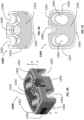
- FIGS. 22-25 show a spinal implant 600 according to another example of the present disclosure.
- Spinal implant 600 is suitable for implantation from a posterior approach.
- Spinal implant 600 is similar to spinal implant 100, and therefore like elements are referred to with similar numerals within the 600-series of numbers.
- spinal implant 600 includes anterior solid wall 602, posterior solid wall 604, medial solid wall 606 and lateral solid wall 608.
- spinal implant 600 has two cavities 616 and 619 separated by a crossbar 623. Each cavity has a lateral window 620, 621 on medial solid wall 606 and lateral solid wall 608.
- second threaded hole 624 to engage with an insertion tool (not shown) is located on posterior solid wall 604.
- An anti-rotation slot 622 is also located on the posterior solid wall to aid implantation of spinal implant 600.
- a window 621 through crossbar 623 links first cavity 618 and second cavity 619 as best shown in FIG. 23 .
- Window 621 is covered with porous inner layer to facilitate bone growth across the first and second cavity.
- spinal implant 600 has teeth 616 instead of the serrations discussed in the previous embodiments.
- Teeth 616 are generally integrated to the solid peripheral walls to add strength to the spinal implant construct. Teeth 616 are also integrated along crossbar 623 and provide additional support for teeth located away from the side walls.
- Nose 609 shown in FIG. 25 is generally wedge-shaped with a smooth exterior surface to distract vertebral bodies during insertion of the spinal implant into the intervertebral space.
- solid wall thickness at the nose may be 1.5 mm
- lateral solid wall and medial solid wall thickness may be 0.75 mm to optimize spinal implant 600 strengthen and potential for bone ingrowth vis-à-vis inner porous layer and graft windows.
- spinal implant 700 is similar to spinal implant 600, and therefore like elements are referred to with similar numerals within the 700-series of numbers.
- spinal implant 700 includes anterior solid wall 702, posterior solid wall 704, medial solid wall 706 and lateral solid wall 708.
- spinal 700 does not have central cavities. Instead, the entire internal region bounded by the solid peripheral walls contains porous material. Consequently, spinal implant 700 provides a greater surface area and volume for bone ingrowth.
- Crossbar 723 is also completely solid without any openings as best seen in FIG. 27 .
- FIGS. 28 and 29 show a spinal implant 800 according to another example of the present disclosure.
- Spinal implant 800 is similar to spinal implant 200, and therefore like elements are referred to with similar numerals within the 800-series of numbers.
- spinal implant 800 includes anterior solid wall 802, posterior solid wall 804, medial solid wall 806 and lateral solid wall 808.
- Spinal implant 800 includes a wedge-shaped nose 819 to facilitate implant insertion.
- a solid crossbar 857 extending medial-laterally across porous layer 815 provides rigidity to the construct as best shown in FIG. 29 . Radiopaque markers may be provided for visualization of the implant under fluoroscopy imaging.
- spinal implant 900 and spinal implant 1000 are similar to spinal implant 100, and therefore like elements are referred to with similar numerals within the 900-series and 1000-series of numbers.
- spinal implant 900 includes anterior solid wall 902, posterior solid wall 904, medial solid wall 906 and lateral solid wall 908.
- spinal implant 900 does not have serrations.
- spinal implant 900 has ribs 916 extending in the medial-lateral and anterior-posterior direction with greater coverage over inner porous layer. Ribs 916 are teeth that are similar in nature to teeth 616.
- Ribs 916 serve the same purpose as the serrations of previously described embodiments and as teeth 616 to resist migration of the implant 900 within the intervertebral space, and to have optimal spacing to facilitate bone growth into the superior and inferior surfaces of implant 900.
- Spinal implant 1000 includes similar ribs 1016 but does not have a central cavity but is instead completely packed with porous material.
- FIGS. 34 and 35 show a spinal implant 1100 according to another example of the present disclosure.
- Spinal implant 1100 is similar to spinal implant 300, and therefore like elements are referred to with similar numerals within the 800-series of numbers.
- spinal implant 1100 includes anterior solid wall 1102, posterior solid wall 1104, medial solid wall 1106 and lateral solid wall 1108.
- Spinal implant 1100 does not include central cavities but is instead completely packed with porous material to have two porous layers 1118 and 1119 separated by channel 1146 as best shown in FIG. 35 . Cavities packed with porous material enhance rigidity of spinal implant 1100 and also improve bone-porous material ingrowth.
- spinal implant 1200 and spinal implant 1300 are similar to spinal implant 100, and therefore like elements are referred to with similar numerals within the 1200-series and 1300-series of numbers.
- spinal implant 1200 includes anterior solid wall 1202, posterior solid wall 1204, medial solid wall 1206 and lateral solid wall 1208.
- Spinal implants 1200 and 1300 are configured to be implanted in an anterior-posterior direction with the implants having a tapered shape in an anterior-posterior direction as best shown in FIGS. 36 and 39 .
- Spinal implant 1200 includes a bore hole 1260 configured to receive a fastener (not shown) in a generally superior-inferior direction to secure the implant to a vertebral.
- Two additional bore holes 1262 and 1264 on either side of bore hole 1260 are configured to receive fasteners (not shown) in an inferior-superior direction as best shown in FIG. 36 .
- spinal implant 1300 includes bore holes 1360, 1362 and 1364 to secure fixation of spinal implant 1300 to a vertebral body as best shown in FIG. 39 .
- ribs 1216 and 1316 of spinal implant 1200 and 1300 respectively, extend in a medial-lateral and anterior-posterior direction offering greater coverage over inner porous layers. While spinal implant 1200 has central cavities 1218 and 1219, spinal implant 1300 is completely packed with porous materials as best shown in FIGS. 40 and 41 .
- the implants described above are each offered in a number of footprints, heights, and lordotic angles to adapt to a variety of patient anatomies.
- the implants described above can be manufactured by 3D printing methods or additive manufacturing processes.
- the solid and porous portions of the implants described herein are preferably of material suitable for implantation in a patient and capable of providing the necessary strength and durability required for such application.
- the solid and porous portions are constructed from titanium.
- any other suitable metals or non-metals may be used, and it is contemplated to utilize different materials for the solid and porous portions.
- the porous surfaces may an average pore diameter between 100-1000 microns with a 30-80% porosity, while a preferred embodiment would have a porosity between 50-70%.
- the porous surfaces may also have any thickness, for instance between 500-4500 microns, and preferably between 500-1500 microns. This results in a surface that is both strong enough for use in a spinal implant and maximizes bone growth potential.
- porous portions of implant 10, as well as the solid portions can be created through the use of a 3D printing process such as is disclosed in U.S. Patent Nos. 7,537,664 and 8,147,861 ; U.S. Patent Application Publications Nos. 2006/0147332 , 2007/0142914 , 2008/0004709 ; and U.S. Patent Application Serial Nos. 13/441,154 and 13/618,218 . It is also contemplated to form any porous portion via another known or hereafter developed procedure, such as laser etching.
- a distal end of the shaft 1402 includes a threaded tip 1408 sized to engage with a threaded hole in a spinal implant.
- alignment post 1410 is sized to engage with a through hole in the spinal implant to serve as an alignment guide by preventing rotation of the spinal implant when alignment post 1410 and threaded tip 1408 are engaged with the spinal implant.
- Threaded tip 1408 can be engaged and disengaged from the spinal implant by rotating knob 1402.
- inserter 1400 has a threaded tip to engage with spinal implant 100 in this example, other examples can have a snap-fit, ball-detent, friction fit or other mechanism at the distal end of the inserter to engage and disengage with a spinal implant.
- the alignment post can be a spring-loaded retractable element to allow for easy engagement and disengagement from the spinal implant.
- An anterior cervical plate 1500 can also simultaneously secured between inserter 1400 and spinal implant 100 prior to placement of the spinal implant as best shown in FIG. 43 .
- Anterior cervical plate 1500 includes a plurality of screw holes 1504 for receiving bone screws and a plurality of blocker holes to receive blockers 1502.
- Blocker 1502 includes a washer and a retaining screw combination. Examples of bone plates that may be used with inserter 1400 are disclosed in U.S. Provisional Patent Application No. 62/653,877 . Threaded tip 1408 and alignment post 1410 are placed through the screw holes of anterior cervical plate 1500 and extend therethrough as best shown in FIG.
- Inserter 1400 can now be engaged with spinal implant 100 by inserting alignment post 1410 into anti-rotation slot 122 and threadingly engaging threaded tip 1410 to threaded screw hole 124 by rotating knob 1412. After securing spinal implant 100 and anterior cervical plate 1500 to inserter 1400, an operator can precisely place this assembly to a target surgical site by utilizing the inserter 1400 to ensure precise alignment of spinal implant 100 and anterior cervical plate 1500 with reference to the surgical site. While spinal implant 100 and anterior cervical plate 1500 are shown in this example, any other spinal implant and/or plate can be used in conjunction with the inserter disclosed herein. In other examples, the inserter can directly contact and place a spinal implant without a spinal plate.
Landscapes
- Health & Medical Sciences (AREA)
- Engineering & Computer Science (AREA)
- Biomedical Technology (AREA)
- Orthopedic Medicine & Surgery (AREA)
- Neurology (AREA)
- Transplantation (AREA)
- Heart & Thoracic Surgery (AREA)
- Oral & Maxillofacial Surgery (AREA)
- Cardiology (AREA)
- Vascular Medicine (AREA)
- Life Sciences & Earth Sciences (AREA)
- Animal Behavior & Ethology (AREA)
- General Health & Medical Sciences (AREA)
- Public Health (AREA)
- Veterinary Medicine (AREA)
- Prostheses (AREA)
- Physical Education & Sports Medicine (AREA)
Claims (14)
- Implant rachidien (100, 300, 400, 500) comprenant :un cadre plein comportant une paroi pleine médiane (106) définissant une épaisseur de paroi pleine médiane (105) indiquée par une épaisseur de surface de paroi pleine médiane transversale à la paroi pleine médiane, une paroi pleine latérale (108) définissant une épaisseur de paroi pleine latérale (107) indiquée par une épaisseur de surface de paroi pleine latérale transversale à la paroi pleine latérale, une paroi pleine postérieure (104) définissant une épaisseur de paroi pleine postérieure indiquée par une épaisseur de surface de paroi pleine postérieure (130) transversale à la paroi pleine postérieure, et une paroi pleine antérieure (102) définissant une épaisseur de paroi pleine antérieure (128) indiquée par une épaisseur de surface de paroi pleine antérieure transversale à la paroi pleine antérieure ;une couche interne poreuse disposée dans le cadre plein, la couche interne poreuse ayant une surface supérieure exposée (110), une surface inférieure exposée (112), une paroi poreuse médiane définissant une épaisseur de paroi poreuse médiane indiquée par une épaisseur de surface de paroi poreuse médiane transversale à la paroi poreuse médiane, une paroi poreuse latérale définissant une épaisseur de paroi poreuse latérale indiquée par une épaisseur de surface de paroi poreuse latérale transversale à la paroi poreuse latérale, une paroi poreuse postérieure définissant une épaisseur de paroi poreuse postérieure indiquée par une épaisseur de surface de paroi poreuse postérieure transversale à la paroi poreuse postérieure, et une paroi poreuse antérieure définissant une épaisseur de paroi poreuse antérieure indiquée par une épaisseur de surface de paroi poreuse antérieure transversale à la paroi poreuse antérieure,une première cavité intérieure (118) s'étendant dans une direction supérieure-inférieure et définie par la couche intérieure poreuse et le cadre plein ;dans lequel le cadre plein comporte une ou plusieurs nervures (116) s'étendant de la paroi médiane à la paroi latérale au-dessus de la surface supérieure et inférieure, etl'épaisseur de la paroi postérieure poreuse et l'épaisseur de la paroi antérieure poreuse sont inférieures à l'épaisseur de la paroi pleine postérieure et à l'épaisseur de la paroi pleine antérieure respectivement, et l'épaisseur de la paroi médiane poreuse et l'épaisseur de la paroi latérale poreuse sont supérieures à l'épaisseur de la paroi pleine médiane et à l'épaisseur de la paroi pleine latérale respectivement.
- Implant rachidien (300) selon la revendication 1, dans lequel l'implant rachidien a deux cavités internes ou plus (318, 319), chaque cavité s'étendant dans une direction supérieure-inférieure et étant définie par la couche interne poreuse et le cadre plein.
- Implant rachidien selon l'une des revendications 1 et 2, dans lequel l'implant rachidien a une seconde cavité interne s'étendant dans une direction supérieure-inférieure et définie par la couche interne poreuse et le cadre plein, une barre transversale s'étendant médialement-latéralement et séparant les deux cavités, la barre transversale étant définie par le cadre plein et comprenant une fenêtre pour permettre la communication des fluides entre la première et la seconde cavité.
- Implant rachidien selon la revendication 3, dans lequel la fenêtre est définie par la couche interne poreuse.
- Implant spinal (100) selon l'une des revendications 1 à 4, dans lequel l'épaisseur de la paroi pleine latérale et l'épaisseur de la paroi pleine médiane sont d'au moins 0,25 mm.
- Implant rachidien (100) selon l'une des revendications 1 à 5, dans lequel l'épaisseur de la paroi pleine latérale (105) et l'épaisseur de la paroi pleine médiane (107) varient le long d'une direction antéro-postérieure, l'épaisseur de la paroi pleine ayant une épaisseur maximale aux extrémités antérieure et postérieure et une épaisseur minimale entre les extrémités antérieure et postérieure.
- Implant spinal (100) selon l'une des revendications 1 à 6, dans lequel les nervures (116) ont une section triangulaire, un sommet de la section triangulaire s'étendant à l'écart de l'implant spinal.
- Implant spinal (100) selon la revendication 7, dans lequel les nervures (116) s'engagent dans les plaques d'extrémité vertébrales d'un premier et d'un second corps vertébral pour fixer l'implant spinal entre les corps vertébraux.
- Implant rachidien (100) selon l'une des revendications 1 à 8, dans lequel l'implant rachidien comporte une ou plusieurs cavités (120) s'étendant dans une direction médio-latérale.
- Implant spinal (100) selon l'une des revendications 1 à 9, dans lequel la paroi antérieure et la paroi postérieure comprennent au moins un trou (122, 124) pour s'engager dans un outil d'insertion chirurgicale (1400).
- Implant spinal (100) selon l'une des revendications 1 à 10, dans lequel les parois antérieure et postérieure comprennent au moins un trou (122, 124) en communication fluide avec la cavité interne (118).
- Implant rachidien (100) selon l'une des revendications 1 à 11, dans lequel le cadre plein est en métal.
- Implant rachidien (100) selon la revendication 12, dans lequel le métal est du titane.
- Implant rachidien (100) selon l'une des revendications 1 à 13, dans lequel la couche poreuse interne a un diamètre moyen de pore compris entre 400 et 500 microns.
Applications Claiming Priority (1)
| Application Number | Priority Date | Filing Date | Title |
|---|---|---|---|
| US201762560910P | 2017-09-20 | 2017-09-20 |
Publications (2)
| Publication Number | Publication Date |
|---|---|
| EP3459502A1 EP3459502A1 (fr) | 2019-03-27 |
| EP3459502B1 true EP3459502B1 (fr) | 2024-05-22 |
Family
ID=63642910
Family Applications (1)
| Application Number | Title | Priority Date | Filing Date |
|---|---|---|---|
| EP18195567.5A Active EP3459502B1 (fr) | 2017-09-20 | 2018-09-19 | Implants vertébraux |
Country Status (4)
| Country | Link |
|---|---|
| US (4) | US10835388B2 (fr) |
| EP (1) | EP3459502B1 (fr) |
| JP (2) | JP7378917B2 (fr) |
| AU (3) | AU2018232971B2 (fr) |
Families Citing this family (58)
| Publication number | Priority date | Publication date | Assignee | Title |
|---|---|---|---|---|
| US9750616B2 (en) | 2012-02-17 | 2017-09-05 | Spinal Elements, Inc. | Interbody fusion device |
| US11147688B2 (en) | 2013-10-15 | 2021-10-19 | Si-Bone Inc. | Implant placement |
| JP6542362B2 (ja) * | 2014-09-18 | 2019-07-10 | エスアイ−ボーン・インコーポレイテッドSi−Bone, Inc. | マトリックス・インプラント |
| AU2016200179B2 (en) | 2015-01-14 | 2020-09-17 | Stryker European Operations Holdings Llc | Spinal implant with porous and solid surfaces |
| US10342678B2 (en) | 2015-02-02 | 2019-07-09 | Spinal Elements, Inc. | Interbody implant inserter |
| EP3288501B1 (fr) | 2015-04-29 | 2020-11-25 | Institute For Musculoskeletal Science And Education, Ltd. | Implants helicoidaux |
| US10492921B2 (en) | 2015-04-29 | 2019-12-03 | Institute for Musculoskeletal Science and Education, Ltd. | Implant with arched bone contacting elements |
| US10449051B2 (en) | 2015-04-29 | 2019-10-22 | Institute for Musculoskeletal Science and Education, Ltd. | Implant with curved bone contacting elements |
| US10709570B2 (en) | 2015-04-29 | 2020-07-14 | Institute for Musculoskeletal Science and Education, Ltd. | Implant with a diagonal insertion axis |
| CA2930123A1 (fr) | 2015-05-18 | 2016-11-18 | Stryker European Holdings I, Llc | Implants partiellement resorbables et methodes |
| EP3528724B1 (fr) | 2016-10-24 | 2024-02-07 | Corelink, LLC | Espaceur intervertébral pour spondylodèse |
| US11033394B2 (en) | 2016-10-25 | 2021-06-15 | Institute for Musculoskeletal Science and Education, Ltd. | Implant with multi-layer bone interfacing lattice |
| US10478312B2 (en) | 2016-10-25 | 2019-11-19 | Institute for Musculoskeletal Science and Education, Ltd. | Implant with protected fusion zones |
| US10512549B2 (en) | 2017-03-13 | 2019-12-24 | Institute for Musculoskeletal Science and Education, Ltd. | Implant with structural members arranged around a ring |
| US10357377B2 (en) | 2017-03-13 | 2019-07-23 | Institute for Musculoskeletal Science and Education, Ltd. | Implant with bone contacting elements having helical and undulating planar geometries |
| EP3459502B1 (fr) * | 2017-09-20 | 2024-05-22 | Stryker European Operations Holdings LLC | Implants vertébraux |
| WO2019067584A1 (fr) | 2017-09-26 | 2019-04-04 | Si-Bone Inc. | Systèmes et procédés de décortication de l'articulation sacro-iliaque |
| US10918497B1 (en) * | 2017-10-24 | 2021-02-16 | Omnia Medical, LLC | Multi-material multi-component spinal implant |
| US10940015B2 (en) | 2017-11-21 | 2021-03-09 | Institute for Musculoskeletal Science and Education, Ltd. | Implant with improved flow characteristics |
| US10744001B2 (en) | 2017-11-21 | 2020-08-18 | Institute for Musculoskeletal Science and Education, Ltd. | Implant with improved bone contact |
| WO2019191149A1 (fr) * | 2018-03-26 | 2019-10-03 | The Regents Of The University Of California | Implants médicaux et autres articles manufacturés fondés sur des réseaux de l'os trabéculaires |
| EP4516267A3 (fr) | 2018-03-28 | 2025-05-21 | SI-Bone, Inc. | Implants filetes et procedes d'utilisation a travers des segments osseux |
| US10617532B2 (en) * | 2018-05-08 | 2020-04-14 | Globus Medical, Inc. | Intervertebral spinal implant |
| US11065126B2 (en) * | 2018-08-09 | 2021-07-20 | Stryker European Operations Holdings Llc | Interbody implants and optimization features thereof |
| US11234838B2 (en) | 2018-09-07 | 2022-02-01 | Additive Implants, Inc. | Dynamic intervertebral spacer implant |
| US10299938B1 (en) | 2018-09-07 | 2019-05-28 | John R. Ehteshami | Dynamic intervertebral spacer implant |
| US11684482B2 (en) | 2018-12-20 | 2023-06-27 | Additive Implants, Inc. | Spondylolisthesis system and methods |
| US11369419B2 (en) | 2019-02-14 | 2022-06-28 | Si-Bone Inc. | Implants for spinal fixation and or fusion |
| JP2022520101A (ja) | 2019-02-14 | 2022-03-28 | エスアイ-ボーン・インコーポレイテッド | 脊椎の固定及び、又は融合のためのインプラント |
| US10905567B2 (en) * | 2019-04-26 | 2021-02-02 | Warsaw Orthopedic, Inc. | Spinal implant system and method |
| JP2022531020A (ja) * | 2019-05-07 | 2022-07-05 | スパイナル・エレメンツ・インコーポレーテッド | 頸部プレートおよびインサーター |
| WO2021032698A1 (fr) * | 2019-08-16 | 2021-02-25 | Biodinamics Ag | Cage en titane à plateforme de support étendue |
| US11123201B2 (en) | 2019-09-24 | 2021-09-21 | Additive Implants, Inc. | Intervertebral spacer |
| WO2021061205A1 (fr) * | 2019-09-25 | 2021-04-01 | Mirus, Llc | Structure en treillis intersomatique |
| EP4061262A1 (fr) | 2019-11-21 | 2022-09-28 | SI-Bone, Inc. | Ensembles de couplage de tige pour constructions de stabilisation osseuse |
| US11672570B2 (en) | 2019-11-27 | 2023-06-13 | Si-Bone Inc. | Bone stabilizing implants and methods of placement across SI Joints |
| AU2020402850A1 (en) | 2019-12-09 | 2022-06-09 | Si-Bone Inc. | Sacro-iliac joint stabilizing implants and methods of implantation |
| US20230147669A1 (en) * | 2020-04-23 | 2023-05-11 | Rv Medical Llc | Screwless interbody device for spinal surgery |
| CA3115863A1 (fr) * | 2020-05-05 | 2021-11-05 | Smed-Ta/Td, Llc | Implants medicaux avec materiau de renforcement |
| IT202000014587A1 (it) * | 2020-06-18 | 2021-12-18 | Sps S R L | Gabbia intersomatica per stabilizzazione vertebrale |
| IT202000014569A1 (it) * | 2020-06-18 | 2021-12-18 | Sps S R L | Gabbia intersomatica per stabilizzazione vertebrale |
| US11844697B2 (en) | 2020-09-03 | 2023-12-19 | Globus Medical, Inc. | Systems and methods for knee arthroplasty |
| US11730603B2 (en) | 2020-09-03 | 2023-08-22 | Globus Medical, Inc. | Systems and methods for knee arthroplasty |
| US20230404773A1 (en) * | 2020-10-02 | 2023-12-21 | K2M, Inc. | Spinal Interbody Implants |
| US12251318B2 (en) | 2020-10-16 | 2025-03-18 | KYOCERA Medical Technologies, Inc. | Surgical implant device incorporating a lattice volume and associated method of manufacture |
| USD942623S1 (en) | 2020-11-13 | 2022-02-01 | Mirus Llc | Spinal implant |
| USD942011S1 (en) | 2020-11-13 | 2022-01-25 | Mirus Llc | Spinal implant |
| USD942624S1 (en) | 2020-11-13 | 2022-02-01 | Mirus Llc | Spinal implant |
| USD944400S1 (en) | 2020-11-13 | 2022-02-22 | Mirus Llc | Spinal implant |
| AU2021397743A1 (en) | 2020-12-09 | 2023-06-22 | Si-Bone Inc. | Sacro-iliac joint stabilizing implants and methods of implantation |
| CN113855201A (zh) * | 2021-09-16 | 2021-12-31 | 天津正天医疗器械有限公司 | 一种镜下腰椎椎间植入件及其使用方法 |
| USD1095838S1 (en) | 2021-10-15 | 2025-09-30 | Rv Medical Llc | Interbody device |
| CN114098933B (zh) | 2021-11-25 | 2024-11-26 | 郝定均 | 一种颈椎骨质疏松前路固定系统 |
| WO2023102533A1 (fr) | 2021-12-03 | 2023-06-08 | Si-Bone Inc. | Cages intersomatique et procédés de stabilisation d'articulation sacro-iliaque |
| WO2024119139A1 (fr) | 2022-12-01 | 2024-06-06 | Percheron Spine, Llc | Implant rachidien et système de pose |
| CN116965982A (zh) * | 2023-05-29 | 2023-10-31 | 上海昕健医疗技术有限公司 | 一种周向防退出的经椎间孔腰椎体间融合器 |
| US12433733B2 (en) | 2023-08-15 | 2025-10-07 | Si-Bone Inc. | Pelvic stabilization implants, methods of use and manufacture |
| WO2025245101A1 (fr) * | 2024-05-23 | 2025-11-27 | Providence Medical Technology, Inc. | Cage et système de plaque |
Family Cites Families (382)
| Publication number | Priority date | Publication date | Assignee | Title |
|---|---|---|---|---|
| US3486505A (en) | 1967-05-22 | 1969-12-30 | Gordon M Morrison | Orthopedic surgical instrument |
| US3641590A (en) | 1970-01-16 | 1972-02-15 | Arthur A Michele | Acetabular replacement prosthesis and method of assembling |
| CA962806A (en) | 1970-06-04 | 1975-02-18 | Ontario Research Foundation | Surgical prosthetic device |
| US3852045A (en) | 1972-08-14 | 1974-12-03 | Battelle Memorial Institute | Void metal composite material and method |
| GB1551705A (en) | 1975-04-28 | 1979-08-30 | Downs Surgicial Ltd | Surgial implant |
| US4501269A (en) | 1981-12-11 | 1985-02-26 | Washington State University Research Foundation, Inc. | Process for fusing bone joints |
| US4612160A (en) | 1984-04-02 | 1986-09-16 | Dynamet, Inc. | Porous metal coating process and mold therefor |
| CA1227902A (fr) | 1984-04-02 | 1987-10-13 | Raymond G. Tronzo | Vis fenestree pour la reparation des fractures de la hanche |
| US4681589A (en) | 1984-06-01 | 1987-07-21 | Tronzo Raymond G | Adjustable acetabular cup prosthesis as part of a total cup replacement system |
| FR2570594B1 (fr) | 1984-09-26 | 1989-02-24 | Kehr Pierre | Prothese vertebrale, en particulier pour vertebres cervicales |
| CH665553A5 (de) | 1985-02-07 | 1988-05-31 | Sulzer Ag | Metallenes knochenimplantat. |
| DE3637314A1 (de) | 1986-11-03 | 1988-05-11 | Lutz Biedermann | Platzhalter-implantat |
| US4834757A (en) | 1987-01-22 | 1989-05-30 | Brantigan John W | Prosthetic implant |
| JPH01136655A (ja) | 1987-11-24 | 1989-05-29 | Asahi Optical Co Ltd | 人工椎間板 |
| US5609635A (en) | 1988-06-28 | 1997-03-11 | Michelson; Gary K. | Lordotic interbody spinal fusion implants |
| CA1333209C (fr) | 1988-06-28 | 1994-11-29 | Gary Karlin Michelson | Implants artificiels pour la soudure osseuse intervertebrale |
| CA1318469C (fr) | 1989-02-15 | 1993-06-01 | Acromed Corporation | Disque artificiel |
| US5458638A (en) | 1989-07-06 | 1995-10-17 | Spine-Tech, Inc. | Non-threaded spinal implant |
| FR2659226B1 (fr) | 1990-03-07 | 1992-05-29 | Jbs Sa | Prothese pour disques intervertebraux et ses instruments d'implantation. |
| DE4040106A1 (de) | 1990-12-12 | 1992-06-17 | Mecron Med Prod Gmbh | Hohlschaftprothese |
| US5192327A (en) | 1991-03-22 | 1993-03-09 | Brantigan John W | Surgical prosthetic implant for vertebrae |
| JP3007903B2 (ja) | 1991-03-29 | 2000-02-14 | 京セラ株式会社 | 人工椎間板 |
| US5180381A (en) | 1991-09-24 | 1993-01-19 | Aust Gilbert M | Anterior lumbar/cervical bicortical compression plate |
| GB9125798D0 (en) | 1991-12-04 | 1992-02-05 | Customflex Limited | Improvements in or relating to spinal vertebrae implants |
| US5358533A (en) | 1992-02-19 | 1994-10-25 | Joint Medical Products Corporation | Sintered coatings for implantable prostheses |
| US5306309A (en) | 1992-05-04 | 1994-04-26 | Calcitek, Inc. | Spinal disk implant and implantation kit |
| US5370692A (en) | 1992-08-14 | 1994-12-06 | Guild Associates, Inc. | Rapid, customized bone prosthesis |
| US5723011A (en) | 1992-12-21 | 1998-03-03 | Zimmer, Inc. | Prosthetic implant and method of making same |
| BE1007549A3 (nl) | 1993-09-21 | 1995-08-01 | Beckers Louis Francois Charles | Implantaat. |
| US5443514A (en) | 1993-10-01 | 1995-08-22 | Acromed Corporation | Method for using spinal implants |
| US5514180A (en) | 1994-01-14 | 1996-05-07 | Heggeness; Michael H. | Prosthetic intervertebral devices |
| US5443515A (en) | 1994-01-26 | 1995-08-22 | Implex Corporation | Vertebral body prosthetic implant with slidably positionable stabilizing member |
| US5431658A (en) | 1994-02-14 | 1995-07-11 | Moskovich; Ronald | Facilitator for vertebrae grafts and prostheses |
| CA2551185C (fr) | 1994-03-28 | 2007-10-30 | Sdgi Holdings, Inc. | Appareil et methode pour stabilisation vertebrale anterieure |
| US5504300A (en) | 1994-04-18 | 1996-04-02 | Zimmer, Inc. | Orthopaedic implant and method of making same |
| BE1008372A3 (nl) | 1994-04-19 | 1996-04-02 | Materialise Nv | Werkwijze voor het vervaardigen van een geperfektioneerd medisch model uitgaande van digitale beeldinformatie van een lichaamsdeel. |
| US5885299A (en) | 1994-09-15 | 1999-03-23 | Surgical Dynamics, Inc. | Apparatus and method for implant insertion |
| FR2733413B1 (fr) | 1995-04-27 | 1997-10-17 | Jbs Sa | Dispositif de cage cervicale destine a la realisation d'une arthrodese intersomatique |
| US5702449A (en) | 1995-06-07 | 1997-12-30 | Danek Medical, Inc. | Reinforced porous spinal implants |
| US6039762A (en) | 1995-06-07 | 2000-03-21 | Sdgi Holdings, Inc. | Reinforced bone graft substitutes |
| US5683394A (en) | 1995-09-29 | 1997-11-04 | Advanced Spine Fixation Systems, Inc. | Fusion mass constrainer |
| US5734959A (en) | 1995-10-12 | 1998-03-31 | Zimmer, Inc. | Method of making an orthopaedic implant having a porous surface using an organic binder |
| US5709683A (en) | 1995-12-19 | 1998-01-20 | Spine-Tech, Inc. | Interbody bone implant having conjoining stabilization features for bony fusion |
| FR2747034B1 (fr) | 1996-04-03 | 1998-06-19 | Scient X | Systeme de contention et de fusion intersomatique |
| US5702455A (en) | 1996-07-03 | 1997-12-30 | Saggar; Rahul | Expandable prosthesis for spinal fusion |
| DE59610079D1 (de) | 1996-09-04 | 2003-02-27 | Synthes Ag | Zwischenwirbel-implantat |
| FR2754702B1 (fr) | 1996-10-18 | 1999-01-08 | Medinov Amp | Dispositif pour solidariser au moins deux corps vertebraux |
| CA2269342C (fr) | 1996-10-23 | 2006-09-12 | Sdgi Holdings, Inc. | Ecarteurs vertebraux |
| US5961554A (en) | 1996-12-31 | 1999-10-05 | Janson; Frank S | Intervertebral spacer |
| ES2268267T3 (es) | 1997-02-11 | 2007-03-16 | Warsaw Orthopedic, Inc. | Placa cervical anterior para dispositivo de bloqueo de tipo unico. |
| US6039761A (en) | 1997-02-12 | 2000-03-21 | Li Medical Technologies, Inc. | Intervertebral spacer and tool and method for emplacement thereof |
| ZA983955B (en) | 1997-05-15 | 2001-08-13 | Sdgi Holdings Inc | Anterior cervical plating system. |
| US5893889A (en) | 1997-06-20 | 1999-04-13 | Harrington; Michael | Artificial disc |
| US6454769B2 (en) | 1997-08-04 | 2002-09-24 | Spinal Concepts, Inc. | System and method for stabilizing the human spine with a bone plate |
| US6241771B1 (en) | 1997-08-13 | 2001-06-05 | Cambridge Scientific, Inc. | Resorbable interbody spinal fusion devices |
| US20040220571A1 (en) | 1998-04-30 | 2004-11-04 | Richard Assaker | Bone plate assembly |
| US6533786B1 (en) | 1999-10-13 | 2003-03-18 | Sdgi Holdings, Inc. | Anterior cervical plating system |
| US6241769B1 (en) | 1998-05-06 | 2001-06-05 | Cortek, Inc. | Implant for spinal fusion |
| US6800093B2 (en) | 1998-05-06 | 2004-10-05 | Cortek, Inc. | Device for spinal fusion |
| FR2787015B1 (fr) | 1998-12-11 | 2001-04-27 | Dimso Sa | Prothese de disque intervertebral a corps compressible |
| US6200347B1 (en) | 1999-01-05 | 2001-03-13 | Lifenet | Composite bone graft, method of making and using same |
| US6547823B2 (en) | 1999-01-22 | 2003-04-15 | Osteotech, Inc. | Intervertebral implant |
| DE60044258D1 (de) | 1999-01-25 | 2010-06-02 | Warsaw Orthopedic Inc | Instrument zur schaffung eines zwischenwirbelraumes für die aufnahme eines implantates |
| US6113638A (en) | 1999-02-26 | 2000-09-05 | Williams; Lytton A. | Method and apparatus for intervertebral implant anchorage |
| US6325805B1 (en) | 1999-04-23 | 2001-12-04 | Sdgi Holdings, Inc. | Shape memory alloy staple |
| AU768636B2 (en) | 1999-07-07 | 2003-12-18 | Children's Hospital Medical Center | Spinal correction system |
| NZ517741A (en) | 1999-09-14 | 2006-05-26 | Spine Solutions Inc | Insertion instrument for an intervertebral implant |
| US6432107B1 (en) | 2000-01-15 | 2002-08-13 | Bret A. Ferree | Enhanced surface area spinal fusion devices |
| US20040260286A1 (en) | 1999-10-08 | 2004-12-23 | Ferree Bret A. | Intradiscal devices with anti-extrusion keels |
| US6206924B1 (en) | 1999-10-20 | 2001-03-27 | Interpore Cross Internat | Three-dimensional geometric bio-compatible porous engineered structure for use as a bone mass replacement or fusion augmentation device |
| TW491714B (en) | 1999-12-08 | 2002-06-21 | Wen-Jing Shiue | Orthopedic implant having a porous surface and method of making same |
| US6293949B1 (en) | 2000-03-01 | 2001-09-25 | Sdgi Holdings, Inc. | Superelastic spinal stabilization system and method |
| DE20004693U1 (de) | 2000-03-14 | 2001-08-30 | Sofamor Danek GmbH, 94469 Deggendorf | Wirbelimplantat zum Einsetzen in einen Wirbelzwischenraum |
| US6482234B1 (en) | 2000-04-26 | 2002-11-19 | Pearl Technology Holdings, Llc | Prosthetic spinal disc |
| FR2810532B1 (fr) | 2000-06-26 | 2003-05-30 | Stryker Spine Sa | Implant osseux a moyens de blocage annulaires |
| US6730127B2 (en) | 2000-07-10 | 2004-05-04 | Gary K. Michelson | Flanged interbody spinal fusion implants |
| FR2811543B1 (fr) | 2000-07-12 | 2003-07-04 | Spine Next Sa | Implant intersomatique |
| US20020035400A1 (en) | 2000-08-08 | 2002-03-21 | Vincent Bryan | Implantable joint prosthesis |
| US6447546B1 (en) | 2000-08-11 | 2002-09-10 | Dale G. Bramlet | Apparatus and method for fusing opposing spinal vertebrae |
| US6761738B1 (en) | 2000-09-19 | 2004-07-13 | Sdgi Holdings, Inc. | Reinforced molded implant formed of cortical bone |
| US6572654B1 (en) | 2000-10-04 | 2003-06-03 | Albert N. Santilli | Intervertebral spacer |
| AU1312402A (en) | 2000-10-11 | 2002-04-22 | Michael D Mason | Graftless spinal fusion device |
| US6447524B1 (en) | 2000-10-19 | 2002-09-10 | Ethicon Endo-Surgery, Inc. | Fastener for hernia mesh fixation |
| DE10052008C1 (de) | 2000-10-20 | 2002-08-08 | Aesculap Ag & Co Kg | Wirbelersatzkörper |
| AU3279802A (en) | 2000-10-23 | 2002-05-06 | Tyco Healthcare | Absorbable fastener and applying apparatus |
| US6503250B2 (en) | 2000-11-28 | 2003-01-07 | Kamaljit S. Paul | Bone support assembly |
| US20020169507A1 (en) | 2000-12-14 | 2002-11-14 | David Malone | Interbody spine fusion cage |
| HUP0302127A2 (hu) | 2000-12-15 | 2005-12-28 | Spineology, Inc. | Erősítő pánt a porckorong gyűrűeleméhez |
| US6972019B2 (en) | 2001-01-23 | 2005-12-06 | Michelson Gary K | Interbody spinal implant with trailing end adapted to receive bone screws |
| IL156148A0 (en) | 2001-01-30 | 2003-12-23 | Synthes Ag | Bone implant, in particular, an inter-vertebral implant |
| US6576017B2 (en) | 2001-02-06 | 2003-06-10 | Sdgi Holdings, Inc. | Spinal implant with attached ligament and methods |
| US6863689B2 (en) | 2001-07-16 | 2005-03-08 | Spinecore, Inc. | Intervertebral spacer having a flexible wire mesh vertebral body contact element |
| US6673075B2 (en) | 2001-02-23 | 2004-01-06 | Albert N. Santilli | Porous intervertebral spacer |
| US6890355B2 (en) | 2001-04-02 | 2005-05-10 | Gary K. Michelson | Artificial contoured spinal fusion implants made of a material other than bone |
| EP1389978B1 (fr) | 2001-05-01 | 2009-01-07 | Amedica Corporation | Greffe d'os translucide aux rayons x |
| US20120330420A1 (en) | 2001-05-01 | 2012-12-27 | Amedica Corporation | Spinal fusion implants |
| US20050177238A1 (en) | 2001-05-01 | 2005-08-11 | Khandkar Ashok C. | Radiolucent bone graft |
| TW571720U (en) | 2001-05-04 | 2004-01-11 | Chih-I Lin | Spine fastener with support component |
| US7186256B2 (en) | 2001-06-04 | 2007-03-06 | Warsaw Orthopedic, Inc. | Dynamic, modular, single-lock anterior cervical plate system having assembleable and movable segments |
| FR2827156B1 (fr) | 2001-07-13 | 2003-11-14 | Ldr Medical | Dispositif de cage vertebrale avec fixation modulaire |
| US6471725B1 (en) | 2001-07-16 | 2002-10-29 | Third Millenium Engineering, Llc | Porous intervertebral distraction spacers |
| GB0119652D0 (en) | 2001-08-11 | 2001-10-03 | Stanmore Implants Worldwide | Surgical implant |
| ATE398430T1 (de) | 2001-08-24 | 2008-07-15 | Zimmer Gmbh | Künstliche bandscheibe |
| US6890335B2 (en) | 2001-08-24 | 2005-05-10 | Zimmer Spine, Inc. | Bone fixation device |
| CA2356535A1 (fr) | 2001-09-04 | 2003-03-04 | Sylvio Quesnel | Dispositif pour fusion de vertebres |
| US6569201B2 (en) | 2001-09-28 | 2003-05-27 | Depuy Acromed, Inc. | Hybrid composite interbody fusion device |
| US20060142765A9 (en) | 2001-10-15 | 2006-06-29 | Dixon Robert A | Vertebral implant for bone fixation or interbody use |
| KR100464829B1 (ko) | 2001-10-30 | 2005-01-05 | 주식회사 솔고 바이오메디칼 | 척추 추체간 유합 케이지 |
| US7766947B2 (en) | 2001-10-31 | 2010-08-03 | Ortho Development Corporation | Cervical plate for stabilizing the human spine |
| FR2831796B1 (fr) | 2001-11-06 | 2003-12-26 | Ldr Medical | Dispositif d'ancrage osseux pour prothese |
| US8119152B2 (en) | 2001-11-27 | 2012-02-21 | Takiron Co., Ltd. | Implant material and process for producing the same |
| US7238203B2 (en) | 2001-12-12 | 2007-07-03 | Vita Special Purpose Corporation | Bioactive spinal implants and method of manufacture thereof |
| US6740118B2 (en) | 2002-01-09 | 2004-05-25 | Sdgi Holdings, Inc. | Intervertebral prosthetic joint |
| DE60304233T2 (de) | 2002-01-11 | 2007-01-18 | Zimmer Gmbh | Implantierbare Knieprothese mit Kielen |
| US7303564B2 (en) | 2002-02-01 | 2007-12-04 | Spinal Concepts, Inc. | Spinal plate extender system and method |
| US6923830B2 (en) | 2002-02-02 | 2005-08-02 | Gary K. Michelson | Spinal fusion implant having deployable bone engaging projections |
| US6740186B2 (en) | 2002-02-20 | 2004-05-25 | Zimmer Technology, Inc. | Method of making an orthopeadic implant having a porous metal surface |
| US6991653B2 (en) | 2002-03-21 | 2006-01-31 | Sdgi Holdings, Inc. | Vertebral body and disc space replacement devices |
| US6726720B2 (en) | 2002-03-27 | 2004-04-27 | Depuy Spine, Inc. | Modular disc prosthesis |
| DE20205016U1 (de) | 2002-03-30 | 2003-08-14 | Mathys Medizinaltechnik Ag, Bettlach | Chirurgisches Implantat |
| JP4388468B2 (ja) | 2002-05-06 | 2009-12-24 | ウォーソー・オーソペディック・インコーポレーテッド | 隣接する椎骨を離すための器具 |
| US8105366B2 (en) | 2002-05-30 | 2012-01-31 | Warsaw Orthopedic, Inc. | Laminoplasty plate with flanges |
| US7918382B2 (en) | 2002-06-18 | 2011-04-05 | Zimmer Technology, Inc. | Method for attaching a porous metal layer to a metal substrate |
| US6945448B2 (en) | 2002-06-18 | 2005-09-20 | Zimmer Technology, Inc. | Method for attaching a porous metal layer to a metal substrate |
| WO2004016217A2 (fr) | 2002-08-15 | 2004-02-26 | David Gerber | Disque intervertebral artificiel controle |
| WO2004016205A2 (fr) | 2002-08-15 | 2004-02-26 | Coppes Justin K | Disque intervertebral artificiel |
| US7862597B2 (en) | 2002-08-22 | 2011-01-04 | Warsaw Orthopedic, Inc. | System for stabilizing a portion of the spine |
| WO2004026193A2 (fr) | 2002-09-20 | 2004-04-01 | Sdgi Holdings, Inc. | Instrument et procede d'extraction chirurgicale |
| US7497859B2 (en) | 2002-10-29 | 2009-03-03 | Kyphon Sarl | Tools for implanting an artificial vertebral disk |
| US20060147332A1 (en) | 2004-12-30 | 2006-07-06 | Howmedica Osteonics Corp. | Laser-produced porous structure |
| CA2448592C (fr) | 2002-11-08 | 2011-01-11 | Howmedica Osteonics Corp. | Surface poreuse produite par laser |
| US7204852B2 (en) | 2002-12-13 | 2007-04-17 | Spine Solutions, Inc. | Intervertebral implant, insertion tool and method of inserting same |
| US20040148028A1 (en) | 2002-12-19 | 2004-07-29 | Ferree Bret A. | Artificial disc replacement (ADR) extraction methods and apparatus |
| US20040133279A1 (en) | 2003-01-06 | 2004-07-08 | Krueger David J. | Surgical implants for use as spinal spacers |
| WO2004069106A1 (fr) | 2003-02-06 | 2004-08-19 | Synthes Ag Chur | Implant intervertebral |
| US7364589B2 (en) | 2003-02-12 | 2008-04-29 | Warsaw Orthopedic, Inc. | Mobile bearing articulating disc |
| US7235101B2 (en) | 2003-09-15 | 2007-06-26 | Warsaw Orthopedic, Inc. | Revisable prosthetic device |
| US20040167632A1 (en) | 2003-02-24 | 2004-08-26 | Depuy Products, Inc. | Metallic implants having roughened surfaces and methods for producing the same |
| US20040176853A1 (en) | 2003-03-05 | 2004-09-09 | Sennett Andrew R. | Apparatus and method for spinal fusion using posteriorly implanted devices |
| US7278997B1 (en) | 2003-03-07 | 2007-10-09 | Theken Spine, Llc | Instrument guide and implant holder |
| US7060097B2 (en) | 2003-03-31 | 2006-06-13 | Depuy Spine, Inc. | Method and apparatus for implant stability |
| US7819903B2 (en) | 2003-03-31 | 2010-10-26 | Depuy Spine, Inc. | Spinal fixation plate |
| US7112222B2 (en) | 2003-03-31 | 2006-09-26 | Depuy Spine, Inc. | Anterior lumbar interbody fusion cage with locking plate |
| WO2004089240A2 (fr) | 2003-04-04 | 2004-10-21 | Theken Disc, Llc | Prothese de disque artificiel |
| US20040204712A1 (en) | 2003-04-09 | 2004-10-14 | Eric Kolb | Bone fixation plates |
| US7169150B2 (en) | 2003-04-25 | 2007-01-30 | Warsaw Orthopedic, Inc. | Non-metallic orthopedic plate |
| US6945973B2 (en) | 2003-05-01 | 2005-09-20 | Nuvasive, Inc. | Slidable bone plate system |
| DE20307773U1 (de) | 2003-05-19 | 2004-09-23 | Metz-Stavenhagen, Peter, Dr.med. | Vorrichtung zum Einrichten einer menschlichen oder tierischen Wirbelsäule |
| US7048766B2 (en) | 2003-06-06 | 2006-05-23 | Ferree Bret A | Methods and apparatus for total disc replacements with oblique keels |
| US8062270B2 (en) | 2003-07-15 | 2011-11-22 | Spinal Generations, Llc | Method and device for delivering medicine to bone |
| US7811329B2 (en) | 2003-07-31 | 2010-10-12 | Globus Medical | Transforaminal prosthetic spinal disc replacement and methods thereof |
| FR2858546B1 (fr) | 2003-08-04 | 2006-04-28 | Spine Next Sa | Prothese de disque intervertebral |
| US7625375B2 (en) | 2003-08-06 | 2009-12-01 | Warsaw Orthopedic, Inc. | Systems and techniques for stabilizing the spine and placing stabilization systems |
| US7857839B2 (en) | 2003-09-03 | 2010-12-28 | Synthes Usa, Llc | Bone plate with captive clips |
| US20050049595A1 (en) | 2003-09-03 | 2005-03-03 | Suh Sean S. | Track-plate carriage system |
| US7655010B2 (en) | 2003-09-30 | 2010-02-02 | Depuy Spine, Inc. | Vertebral fusion device and method for using same |
| US7306605B2 (en) | 2003-10-02 | 2007-12-11 | Zimmer Spine, Inc. | Anterior cervical plate |
| GB0325421D0 (en) | 2003-10-30 | 2003-12-03 | Gill Steven S | An intervertebral prosthesis |
| GB0325647D0 (en) | 2003-11-03 | 2003-12-10 | Finsbury Dev Ltd | Prosthetic implant |
| US7320707B2 (en) | 2003-11-05 | 2008-01-22 | St. Francis Medical Technologies, Inc. | Method of laterally inserting an artificial vertebral disk replacement implant with crossbar spacer |
| US7837732B2 (en) | 2003-11-20 | 2010-11-23 | Warsaw Orthopedic, Inc. | Intervertebral body fusion cage with keels and implantation methods |
| US20050149192A1 (en) | 2003-11-20 | 2005-07-07 | St. Francis Medical Technologies, Inc. | Intervertebral body fusion cage with keels and implantation method |
| US7503935B2 (en) | 2003-12-02 | 2009-03-17 | Kyphon Sarl | Method of laterally inserting an artificial vertebral disk replacement with translating pivot point |
| US7001672B2 (en) | 2003-12-03 | 2006-02-21 | Medicine Lodge, Inc. | Laser based metal deposition of implant structures |
| US6970233B2 (en) | 2003-12-03 | 2005-11-29 | Texas Instruments Incorporated | System and method for custom-polarized photolithography illumination |
| US7588600B2 (en) | 2003-12-10 | 2009-09-15 | Axiomed Spine Corporation | Method for replacing a damaged spinal disc |
| US7255713B2 (en) | 2003-12-18 | 2007-08-14 | Malek Michel H | Systems and methods for agent delivery |
| US7166110B2 (en) | 2004-01-09 | 2007-01-23 | Yundt Kent D | Method, system and apparatus for interbody fusion |
| US7625379B2 (en) | 2004-01-26 | 2009-12-01 | Warsaw Orthopedic, Inc. | Methods and instrumentation for inserting intervertebral grafts and devices |
| US7850733B2 (en) | 2004-02-10 | 2010-12-14 | Atlas Spine, Inc. | PLIF opposing wedge ramp |
| US8900277B2 (en) | 2004-02-26 | 2014-12-02 | Pioneer Surgical Technology, Inc. | Bone plate system |
| AU2005225208B2 (en) | 2004-03-26 | 2009-11-19 | Nuvasive, Inc. | Porous implant for spinal disc nucleus replacement |
| US8070816B2 (en) | 2004-03-29 | 2011-12-06 | 3Hbfm, Llc | Arthroplasty spinal prosthesis and insertion device |
| US8236034B2 (en) | 2004-04-19 | 2012-08-07 | Globus Medical, Inc. | Bone fixation plate |
| JP4917027B2 (ja) | 2004-06-30 | 2012-04-18 | シナジー ディスク リプレイスメント, インコーポレイテッド | 人工椎間板 |
| US8021428B2 (en) | 2004-06-30 | 2011-09-20 | Depuy Spine, Inc. | Ceramic disc prosthesis |
| US8414648B2 (en) | 2004-08-09 | 2013-04-09 | Si-Bone Inc. | Apparatus, systems, and methods for achieving trans-iliac lumbar fusion |
| US8425570B2 (en) | 2004-08-09 | 2013-04-23 | Si-Bone Inc. | Apparatus, systems, and methods for achieving anterior lumbar interbody fusion |
| US8470004B2 (en) | 2004-08-09 | 2013-06-25 | Si-Bone Inc. | Apparatus, systems, and methods for stabilizing a spondylolisthesis |
| US8444693B2 (en) | 2004-08-09 | 2013-05-21 | Si-Bone Inc. | Apparatus, systems, and methods for achieving lumbar facet fusion |
| US8986348B2 (en) | 2004-08-09 | 2015-03-24 | Si-Bone Inc. | Systems and methods for the fusion of the sacral-iliac joint |
| US20060036251A1 (en) | 2004-08-09 | 2006-02-16 | Reiley Mark A | Systems and methods for the fixation or fusion of bone |
| US20060036250A1 (en) | 2004-08-12 | 2006-02-16 | Lange Eric C | Antero-lateral plating systems for spinal stabilization |
| BRPI0515868A (pt) | 2004-09-23 | 2008-08-12 | Spine Solutions Inc | implante, cinzel, conjunto de um implante, dispositivo para manter um espaço intervertebral aberto, ferramenta de montagem para montar um implante de um disco intervertebral, introdutor para inserir um implante, métodos para inserir um implante intervertebral, para determinar a posição e o tamanho ótimos de um implante intervertebral, para preparar um espaço intervertebral e para posicionar e fixar um implante intervertebral e usos de um implante, de um conjunto de implantes, de dois afastadores e de um batente ajustável |
| US7780731B2 (en) | 2004-11-26 | 2010-08-24 | Spine Solutions, Inc. | Intervertebral implant |
| US20060089656A1 (en) | 2004-10-22 | 2006-04-27 | Sdgi Holdings, Inc. | Revision instruments |
| US8029512B2 (en) | 2004-10-26 | 2011-10-04 | Pioneer Surgical Technology | Spinal stabilization device and methods |
| EP1814492A2 (fr) | 2004-11-15 | 2007-08-08 | Disc-O-Tech Medical Technologies, Ltd. | Prothese assemblee formant un disque |
| US7931678B2 (en) | 2004-12-08 | 2011-04-26 | Depuy Spine, Inc. | Hybrid spinal plates |
| US20060122603A1 (en) | 2004-12-08 | 2006-06-08 | Depuy Spine, Inc. | Hybrid bone screw and plate systems |
| FR2879436B1 (fr) | 2004-12-22 | 2007-03-09 | Ldr Medical | Prothese de disque intervertebral |
| CA2585417A1 (fr) | 2005-01-08 | 2006-07-13 | Alphaspine, Inc. | Dispositif disque modulaire |
| JP5028276B2 (ja) | 2005-01-19 | 2012-09-19 | ケー2エム, インコーポレイテッド | 剛体構造物へのエラストマーの固定 |
| US8911498B2 (en) | 2005-02-10 | 2014-12-16 | DePuy Synthes Products, LLC | Intervertebral prosthetic disc |
| US7722622B2 (en) | 2005-02-25 | 2010-05-25 | Synthes Usa, Llc | Implant insertion apparatus and method of use |
| US7500976B2 (en) | 2005-03-11 | 2009-03-10 | Synthes Usa, Llc | Translational scissor plate fixation system |
| US8266780B2 (en) | 2005-04-21 | 2012-09-18 | Biomet Manufacturing Corp. | Method and apparatus for use of porous implants |
| US8562685B2 (en) | 2005-05-06 | 2013-10-22 | Titan Spine, Llc | Spinal implant and integration plate for optimizing vertebral endplate contact load-bearing edges |
| US8262737B2 (en) | 2005-05-06 | 2012-09-11 | Titan Spine, Llc | Composite interbody spinal implant having openings of predetermined size and shape |
| US8758443B2 (en) | 2005-05-06 | 2014-06-24 | Titan Spine, Llc | Implants with integration surfaces having regular repeating surface patterns |
| US9168147B2 (en) | 2005-05-06 | 2015-10-27 | Titan Spine, Llc | Self-deploying locking screw retention device |
| US8591590B2 (en) | 2005-05-06 | 2013-11-26 | Titan Spine, Llc | Spinal implant having a transverse aperture |
| US8545568B2 (en) | 2005-05-06 | 2013-10-01 | Titan Spine, Llc | Method of using instruments and interbody spinal implants to enhance distraction |
| US11096796B2 (en) | 2005-05-06 | 2021-08-24 | Titan Spine, Llc | Interbody spinal implant having a roughened surface topography on one or more internal surfaces |
| US20120312779A1 (en) * | 2005-05-06 | 2012-12-13 | Titian Spine, LLC | Methods for manufacturing implants having integration surfaces |
| US8758442B2 (en) | 2005-05-06 | 2014-06-24 | Titan Spine, Llc | Composite implants having integration surfaces composed of a regular repeating pattern |
| US8814939B2 (en) | 2005-05-06 | 2014-08-26 | Titan Spine, Llc | Implants having three distinct surfaces |
| US8551176B2 (en) | 2005-05-06 | 2013-10-08 | Titan Spine, Llc | Spinal implant having a passage for enhancing contact between bone graft material and cortical endplate bone |
| US8585765B2 (en) | 2005-05-06 | 2013-11-19 | Titan Spine, Llc | Endplate-preserving spinal implant having a raised expulsion-resistant edge |
| US8992622B2 (en) | 2005-05-06 | 2015-03-31 | Titan Spine, Llc | Interbody spinal implant having a roughened surface topography |
| US20120303127A1 (en) | 2005-05-06 | 2012-11-29 | Titan Spine, Llc | Implants having internal features for graft retention and load transfer between implant and vertebrae |
| US8585767B2 (en) | 2005-05-06 | 2013-11-19 | Titan Spine, Llc | Endplate-preserving spinal implant with an integration plate having durable connectors |
| US8617248B2 (en) | 2005-05-06 | 2013-12-31 | Titan Spine, Llc | Spinal implant having variable ratios of the integration surface area to the axial passage area |
| US8480749B2 (en) | 2005-05-06 | 2013-07-09 | Titan Spine, Llc | Friction fit and vertebral endplate-preserving spinal implant |
| US8562684B2 (en) | 2005-05-06 | 2013-10-22 | Titan Spine, Llc | Endplate-preserving spinal implant with an integration plate having a roughened surface topography |
| US7662186B2 (en) | 2005-05-06 | 2010-02-16 | Titan Spine, Llc | Anterior interbody spinal implant |
| US8403991B2 (en) | 2005-05-06 | 2013-03-26 | Titan Spine Llc | Implant with critical ratio of load bearing surface area to central opening area |
| US20110282454A1 (en) | 2010-05-14 | 2011-11-17 | Titan Spine, Llc | Interbody Spinal Implant Having Internally Textured Surfaces |
| US8585766B2 (en) | 2005-05-06 | 2013-11-19 | Titan Spine, Llc | Endplate-preserving spinal implant with an integration plate having durable connectors |
| US9125756B2 (en) | 2005-05-06 | 2015-09-08 | Titan Spine, Llc | Processes for producing regular repeating patterns on surfaces of interbody devices |
| US8435302B2 (en) | 2005-05-06 | 2013-05-07 | Titan Spine, Llc | Instruments and interbody spinal implants enhancing disc space distraction |
| US8777959B2 (en) | 2005-05-27 | 2014-07-15 | Spinecore, Inc. | Intervertebral disc and insertion methods therefor |
| US20060293668A1 (en) | 2005-06-10 | 2006-12-28 | Sdgi Holdings, Inc. | Bone screw locking mechanism and method of use |
| US7686806B2 (en) | 2005-06-15 | 2010-03-30 | Stryker Spine | Anterior cervical plate |
| US8057544B2 (en) | 2005-08-16 | 2011-11-15 | Benvenue Medical, Inc. | Methods of distracting tissue layers of the human spine |
| US20090171461A1 (en) | 2005-08-26 | 2009-07-02 | Magellan Spine Technologies, Inc. | Spinal implants and methods |
| US7731753B2 (en) | 2005-09-01 | 2010-06-08 | Spinal Kinetics, Inc. | Prosthetic intervertebral discs |
| US20070050032A1 (en) | 2005-09-01 | 2007-03-01 | Spinal Kinetics, Inc. | Prosthetic intervertebral discs |
| FR2891135B1 (fr) | 2005-09-23 | 2008-09-12 | Ldr Medical Sarl | Prothese de disque intervertebral |
| US20070123884A1 (en) | 2005-11-09 | 2007-05-31 | Abdou M S | Bone fixation systems and methods of implantation |
| DE102005056824A1 (de) | 2005-11-24 | 2007-05-31 | Aesculap Ag & Co. Kg | Chirurgisches Führungsinstrument |
| US8728387B2 (en) | 2005-12-06 | 2014-05-20 | Howmedica Osteonics Corp. | Laser-produced porous surface |
| FR2894808B1 (fr) | 2005-12-20 | 2009-02-06 | Spineart Sa Sa | Espaceur discal anatomique et ses applications |
| EP1803513B1 (fr) | 2005-12-30 | 2017-03-29 | Howmedica Osteonics Corp. | Methode pour la fabrication d'implants au moyen de laser |
| US7799079B2 (en) | 2006-01-18 | 2010-09-21 | Zimmer Spine, Inc. | Vertebral fusion device and method |
| US8603171B2 (en) | 2006-01-25 | 2013-12-10 | Mimedx Group, Inc. | Spinal disc implants with flexible keels and methods of fabricating implants |
| US20070179609A1 (en) | 2006-01-27 | 2007-08-02 | Medicinelodge, Inc. | Therapeutic agent eluding implant with percutaneous supply |
| US7635447B2 (en) | 2006-02-17 | 2009-12-22 | Biomet Manufacturing Corp. | Method and apparatus for forming porous metal implants |
| US8137404B2 (en) | 2006-03-28 | 2012-03-20 | Depuy Spine, Inc. | Artificial disc replacement using posterior approach |
| US20070233244A1 (en) | 2006-03-28 | 2007-10-04 | Depuy Spine, Inc. | Artificial Disc Replacement Using Posterior Approach |
| US20070239278A1 (en) | 2006-04-06 | 2007-10-11 | Sdgi Holdings, Inc. | Intervertebral prosthetic devices and methods |
| US7658766B2 (en) | 2006-05-01 | 2010-02-09 | Warsaw Orthopedic, Inc. | Intervertebral implants with covered inner chamber and methods of use |
| US8540778B2 (en) | 2006-06-22 | 2013-09-24 | DePuy Synthes Products, LLC | Tibial insert having multiple keels |
| WO2008005380A2 (fr) | 2006-06-30 | 2008-01-10 | Alphatec Spine, Inc. | Système de plaque de fixation osseuse |
| US7780676B2 (en) | 2006-07-11 | 2010-08-24 | Ebi, Llc | Intervertebral implantation apparatus |
| US20080051901A1 (en) | 2006-07-28 | 2008-02-28 | Spinalmotion, Inc. | Spinal Prosthesis with Multiple Pillar Anchors |
| US8118872B2 (en) | 2006-08-10 | 2012-02-21 | Pioneer Surgical Technology, Inc. | System and methods for inserting a spinal disc device into an intervertebral space |
| US20080051902A1 (en) | 2006-08-10 | 2008-02-28 | James Dwyer | Modular intervertebral disc prosthesis and method of replacing an intervertebral disc |
| US8147861B2 (en) | 2006-08-15 | 2012-04-03 | Howmedica Osteonics Corp. | Antimicrobial implant |
| US8454621B2 (en) | 2006-09-19 | 2013-06-04 | Warsaw Orthopedic, Inc. | Instruments and methods for spinal implant revision |
| CN101616642A (zh) | 2006-10-16 | 2009-12-30 | 先锋外科技术公司 | 融合装置 |
| US20080161927A1 (en) | 2006-10-18 | 2008-07-03 | Warsaw Orthopedic, Inc. | Intervertebral Implant with Porous Portions |
| US20110282392A1 (en) | 2006-10-30 | 2011-11-17 | Tissue Regeneration Systems, Inc. | Degradable cage for bone fusion |
| US9039768B2 (en) | 2006-12-22 | 2015-05-26 | Medos International Sarl | Composite vertebral spacers and instrument |
| US20080183292A1 (en) | 2007-01-29 | 2008-07-31 | Warsaw Orthopedic, Inc. | Compliant intervertebral prosthetic devices employing composite elastic and textile structures |
| US8403969B2 (en) | 2007-01-31 | 2013-03-26 | K2M, Inc. | Anterior vertebral plate with quick lock screw |
| EP1961433A1 (fr) | 2007-02-20 | 2008-08-27 | National University of Ireland Galway | Substrats poreux pour implantation |
| US8425607B2 (en) | 2007-04-03 | 2013-04-23 | Warsaw Orthopedic, Inc. | Anchor member locking features |
| US8172848B2 (en) | 2007-04-27 | 2012-05-08 | Spinemedica, Llc | Surgical instruments for spinal disc implants and related methods |
| US20100076559A1 (en) | 2007-05-04 | 2010-03-25 | Titan Spine, Llc | Composite telescoping anterior interbody spinal implant |
| US8043346B2 (en) | 2007-05-18 | 2011-10-25 | Custom Spine, Inc. | Anterior cervical plate with independent spring-loaded locking slides for each screw |
| FR2916956B1 (fr) | 2007-06-08 | 2012-12-14 | Ldr Medical | Cage intersomatique,prothese intervertebrale,dispositif d'ancrage et instrumentation d'implantation |
| US8900307B2 (en) | 2007-06-26 | 2014-12-02 | DePuy Synthes Products, LLC | Highly lordosed fusion cage |
| US8500811B2 (en) | 2007-07-02 | 2013-08-06 | Spinal Elements, Inc. | Device and method for delivery of multiple heterogenous orthopedic implants |
| JP5318864B2 (ja) | 2007-07-03 | 2013-10-16 | ヴラームス インステリング ヴール テクノロギシュ オンデルゾーク (ヴイアイティーオー) | 多孔性芯と緻密な表面層から構成された外科用インプラント |
| US8623019B2 (en) | 2007-07-03 | 2014-01-07 | Pioneer Surgical Technology, Inc. | Bone plate system |
| US8361126B2 (en) | 2007-07-03 | 2013-01-29 | Pioneer Surgical Technology, Inc. | Bone plate system |
| US8556944B2 (en) | 2007-07-31 | 2013-10-15 | Stryker Spine | System and method for vertebral body plating |
| US8388663B2 (en) | 2007-09-13 | 2013-03-05 | Stryker Spine | Dynamic cervical plate |
| US8852280B2 (en) | 2007-09-27 | 2014-10-07 | Warsaw Orthopedic, Inc. | Intervertebral implant |
| US8043381B2 (en) | 2007-10-29 | 2011-10-25 | Zimmer Spine, Inc. | Minimally invasive interbody device and method |
| US8906077B2 (en) | 2007-11-09 | 2014-12-09 | Stryker Spine | Cervical plate with a feedback device for selective association with bone screw blocking mechanism |
| US20090164020A1 (en) | 2007-11-28 | 2009-06-25 | Pioneer Surgical Technology, Inc. | Device for Securing an Implant to Tissue |
| US8162950B2 (en) | 2007-12-17 | 2012-04-24 | Stryker Leibinger Gmbh & Co. Kg | Bone plate instrument and method |
| US8092499B1 (en) | 2008-01-11 | 2012-01-10 | Roth Herbert J | Skeletal flexible/rigid rod for treating skeletal curvature |
| US8414651B2 (en) | 2008-01-16 | 2013-04-09 | Aesculap Implant Systems, Llc | Dynamic interbody |
| US8551173B2 (en) | 2008-01-17 | 2013-10-08 | DePuy Synthes Products, LLC | Expandable intervertebral implant and associated method of manufacturing the same |
| CN101952341B (zh) | 2008-02-01 | 2016-03-23 | 辛西斯有限责任公司 | 多孔的生物相容性聚合物材料和方法 |
| US20090198184A1 (en) | 2008-02-05 | 2009-08-06 | Martin David C | Percutaneous biomedical devices with regenerative materials interface |
| US8083796B1 (en) | 2008-02-29 | 2011-12-27 | Nuvasive, Inc. | Implants and methods for spinal fusion |
| WO2009137506A1 (fr) | 2008-05-05 | 2009-11-12 | Pioneer Surgical Technology, Inc | Dispositif de disque intervertébral artificiel à conservation de mouvement |
| US20090287257A1 (en) | 2008-05-16 | 2009-11-19 | Hagen Leslie | Cervical plate |
| US8727387B2 (en) | 2008-05-27 | 2014-05-20 | Springseal, Inc. | Pipe coupling assembly |
| WO2009146377A1 (fr) | 2008-05-28 | 2009-12-03 | Kerflin Orthopedic Innovations, Llc | Instrument d'élongation actionné par fluide pour corriger des malformations orthopédiques |
| US20110106159A1 (en) | 2008-06-05 | 2011-05-05 | Seaspine, Inc. | Spinal fixation plate assembly |
| US20100004747A1 (en) | 2008-07-07 | 2010-01-07 | Jin-Fu Lin | Trans-Vertebral and Intra-Vertebral Plate and Fusion Cage Device for Spinal Interbody Fusion and Method of Operation |
| US20100042218A1 (en) | 2008-08-13 | 2010-02-18 | Nebosky Paul S | Orthopaedic implant with porous structural member |
| WO2010021612A1 (fr) | 2008-08-21 | 2010-02-25 | Warsaw Orthopedic, Inc. | Implant intervertébral comportant des parties poreuses |
| KR20110050466A (ko) | 2008-09-02 | 2011-05-13 | 신세스 게엠바하 | 인접 척추체에 연결되는 블레이드를 구비한 추간 임플란트 |
| WO2010045255A1 (fr) | 2008-10-14 | 2010-04-22 | Praxis Powder Technology, Inc. | Implant spinal intervertébral hybride |
| DE102009014184A1 (de) | 2008-11-07 | 2010-05-20 | Advanced Medical Technologies Ag | Implantat zur Fusion von Wirbelsäulensegmenten |
| US20100137916A1 (en) | 2008-12-03 | 2010-06-03 | Warsaw Orthopedic, Inc., An Indiana Corporation | Spinal plates for stabilizing segments |
| PL2358309T3 (pl) | 2008-12-18 | 2016-04-29 | 4 Web Inc | Implant o strukturze kratownicowej |
| US9486324B2 (en) | 2010-01-22 | 2016-11-08 | Frontier Medical Devices, Inc. | Apparatus and method for stabilizing adjacent bone portions |
| US8157865B2 (en) | 2009-01-22 | 2012-04-17 | Stephen Hochschuler | Apparatus and method for stabilizing adjacent bone portions |
| US8349015B2 (en) | 2009-02-11 | 2013-01-08 | Howmedica Osteonics Corp. | Intervertebral implant with integrated fixation |
| US20100262245A1 (en) | 2009-02-18 | 2010-10-14 | Alfaro Arthur A | Intervertebral spacer |
| US8142435B2 (en) | 2009-02-19 | 2012-03-27 | Aesculap Implant Systems, Llc | Multi-functional surgical instrument and method of use for inserting an implant between two bones |
| US20100222750A1 (en) | 2009-02-27 | 2010-09-02 | Vanderbilt University | Replenishable drug delivery implant for bone and cartilage |
| US8870957B2 (en) | 2009-03-04 | 2014-10-28 | Amendia, Inc. | Implant for mammalian bony segment stabilization |
| US8486115B2 (en) | 2009-03-13 | 2013-07-16 | Lanx, Inc. | Spinal plate assemblies with backout protection cap and methods |
| CN102883668B (zh) | 2009-03-16 | 2016-07-06 | 斯恩蒂斯有限公司 | 在通过侧向进入槽道的脊椎外科手术中用于稳定椎骨的系统和方法 |
| US8636803B2 (en) | 2009-04-07 | 2014-01-28 | Spinal Stabilization Technologies, Llc | Percutaneous implantable nuclear prosthesis |
| US20100262244A1 (en) | 2009-04-14 | 2010-10-14 | Warsaw Orthopedic, Inc. | Metal Coated Implant |
| US8123808B2 (en) | 2009-04-16 | 2012-02-28 | Warsaw Orthopedic, Inc. | Vertebral endplate connection implant and method |
| ES2401539T3 (es) | 2009-07-01 | 2013-04-22 | Biedermann Technologies Gmbh & Co. Kg | Instrumentos adecuados para el uso con tornillos para hueso con un tapón |
| US8337876B2 (en) | 2009-07-10 | 2012-12-25 | Bio2 Technologies, Inc. | Devices and methods for tissue engineering |
| JP5662442B2 (ja) | 2009-07-24 | 2015-01-28 | スパイナル・ユーエスエー・エルエルシー | 骨プレートのネジブロックシステム及び方法 |
| MX2012000992A (es) | 2009-07-24 | 2012-06-27 | Spinal USA LLC | Sistema de placa de hueso y metodos de uso de la misma. |
| US8685031B2 (en) | 2009-09-18 | 2014-04-01 | Spinal Surgical Strategies, Llc | Bone graft delivery system |
| US9173694B2 (en) | 2009-09-18 | 2015-11-03 | Spinal Surgical Strategies, Llc | Fusion cage with combined biological delivery system |
| EP2477578B1 (fr) | 2009-09-23 | 2015-08-19 | Zimmer Spine, Inc. | Implant composite |
| US8827986B2 (en) | 2009-10-19 | 2014-09-09 | Pharmaco-Kinesis Corporation | Remotely activated piezoelectric pump for delivery of biological agents to the intervertebral disc and spine |
| GB0918484D0 (en) | 2009-10-22 | 2009-12-09 | Depuy Int Ltd | A medical implant device |
| WO2011056845A1 (fr) | 2009-11-03 | 2011-05-12 | Howmedica Osteonics Corp. | Implant intervertébral à fixation intégrée |
| US20110196494A1 (en) | 2009-12-04 | 2011-08-11 | Osteo Innovations Llc | Percutaneous interbody spine fusion devices, nuclear support device, spine fracture support device, delivery tools, percutaneous off-angle bone stapling/nailing fixation device and methods of use |
| US9381044B2 (en) | 2010-01-26 | 2016-07-05 | Pioneer Surgical Technology, Inc. | Posterior spinal stabilization plate device |
| US8303879B2 (en) | 2010-02-01 | 2012-11-06 | Sb Technologies, Llc | Composite interbody device and method of manufacture |
| US8500819B2 (en) | 2010-03-05 | 2013-08-06 | Biomet Manufacturing, Llc | Drug delivery and diagnostic system for orthopedic implants |
| AU2011227293A1 (en) | 2010-03-16 | 2012-11-08 | Pinnacle Spine Group, Llc | Intervertebral implants and graft delivery systems and methods |
| US20110301709A1 (en) | 2010-06-03 | 2011-12-08 | Kilian Kraus | Intervertebral implant |
| US20110313532A1 (en) | 2010-06-18 | 2011-12-22 | Jessee Hunt | Bone implant interface system and method |
| EP2595576A1 (fr) | 2010-07-20 | 2013-05-29 | X-spine Systems, Inc. | Implant orthopédique composite présentant un substrat à frottement réduit avec des caractéristiques de frottement primaires et des caractéristiques de frottement secondaires |
| US8500782B2 (en) | 2010-07-22 | 2013-08-06 | Aesculap Implant Systems, Llc | Semi-dynamic fixation plate system |
| US10245152B2 (en) * | 2010-07-23 | 2019-04-02 | Privelop-Spine Ag | Surgical implant |
| US20120071933A1 (en) | 2010-09-21 | 2012-03-22 | Warsaw Orothopedic, Inc. | Retaining mechanism |
| US11529241B2 (en) | 2010-09-23 | 2022-12-20 | DePuy Synthes Products, Inc. | Fusion cage with in-line single piece fixation |
| US20120078373A1 (en) | 2010-09-23 | 2012-03-29 | Thomas Gamache | Stand alone intervertebral fusion device |
| US9044284B2 (en) | 2010-09-29 | 2015-06-02 | Spinal Generations, Llc | Intervertebral insert system |
| GB2499755B (en) | 2010-11-10 | 2014-06-18 | Mitsubishi Materials Corp | Vertebral body spacer |
| US20120123544A1 (en) | 2010-11-16 | 2012-05-17 | Sean Suh | Intervertebral Spacer and Method of Installation Thereof |
| US9925051B2 (en) | 2010-12-16 | 2018-03-27 | Engage Medical Holdings, Llc | Arthroplasty systems and methods |
| US8425604B2 (en) | 2011-01-20 | 2013-04-23 | Warsaw Orthopedic, Inc. | Spinal implant with attachable bone securing component |
| WO2012112598A1 (fr) | 2011-02-14 | 2012-08-23 | Imds Corporation | Système et procédé de retrait d'ancrage osseux |
| CN103561689B (zh) | 2011-03-11 | 2016-01-20 | Fbc设备有限公司 | 脊椎植入物 |
| US9615733B2 (en) | 2011-04-13 | 2017-04-11 | Mayo Foundation For Medical Education And Research | Anterior cervical retractor system |
| US20120265306A1 (en) | 2011-04-14 | 2012-10-18 | Warsaw Orthopedic, Inc. | Spinal implant with attachable bone securing componet |
| US8668723B2 (en) | 2011-07-19 | 2014-03-11 | Neurostructures, Inc. | Anterior cervical plate |
| US20130030529A1 (en) | 2011-07-29 | 2013-01-31 | Jessee Hunt | Implant interface system and method |
| US8992619B2 (en) | 2011-11-01 | 2015-03-31 | Titan Spine, Llc | Microstructured implant surfaces |
| JP6177788B2 (ja) | 2011-11-03 | 2017-08-09 | フォー−ウェブ・インコーポレイテッド | 骨修復時の長さ保存の方法 |
| US8414654B1 (en) | 2011-11-23 | 2013-04-09 | Amendia, Inc. | Bone implants and method of manufacture |
| US10765530B2 (en) * | 2012-06-21 | 2020-09-08 | Renovis Surgical Technologies, Inc. | Surgical implant devices incorporating porous surfaces |
| CA2863865C (fr) | 2012-02-08 | 2021-08-24 | 4-Web, Inc. | Prothese pour articulations spheroides et son procede d'utilisation |
| PL219189B1 (pl) | 2012-03-06 | 2015-03-31 | Lfc Spółka Z Ograniczoną Odpowiedzialnością | Dystansowe urządzenie międzytrzonowe do wprowadzania do trzonu kręgowego biomateriału |
| CA2880825C (fr) * | 2012-03-20 | 2021-03-16 | Titan Spine, Llc | Plaque d'extremite vertebrale d'ajustement par friction et procede de preservation de plaque d'extremite |
| US9180010B2 (en) | 2012-04-06 | 2015-11-10 | Howmedica Osteonics Corp. | Surface modified unit cell lattice structures for optimized secure freeform fabrication |
| US9135374B2 (en) | 2012-04-06 | 2015-09-15 | Howmedica Osteonics Corp. | Surface modified unit cell lattice structures for optimized secure freeform fabrication |
| TW201240653A (en) * | 2012-05-30 | 2012-10-16 | Ossaware Biotech Co Ltd | Hollow-grid medical implant |
| ES2735545T3 (es) * | 2012-06-27 | 2019-12-19 | Titan Spine Inc | Implante espinal que tiene un pasaje para mejorar el contacto entre el material de injerto óseo y la placa terminal cortical ósea |
| EP2877128B8 (fr) | 2012-07-25 | 2018-08-29 | Titan Spine, Inc. | Implants ayant trois surfaces distinctes |
| WO2014028635A1 (fr) | 2012-08-14 | 2014-02-20 | Ball Hieu T | Espaceur intervertébral |
| WO2014052477A1 (fr) | 2012-09-25 | 2014-04-03 | 4Web, Inc. | Implants programmables et procédés d'utilisation d'implants programmables pour réparer des structures osseuses |
| WO2015057604A1 (fr) | 2012-10-19 | 2015-04-23 | Tyber Medical Llc | Dispositif d'ostéotomie de coin et procédé d'utilisation |
| US9387087B2 (en) | 2012-10-19 | 2016-07-12 | Tyber Medical Llc | Orthopedic systems for spine and tracking control |
| US8663332B1 (en) | 2012-12-13 | 2014-03-04 | Ouroboros Medical, Inc. | Bone graft distribution system |
| US20140200670A1 (en) | 2013-01-16 | 2014-07-17 | Spinefrontier Inc | System and method for a spinal stabilization implant assembly |
| US9358120B2 (en) | 2013-03-14 | 2016-06-07 | DePuy Synthes Products, Inc. | Expandable coil spinal implant |
| US9238319B2 (en) | 2013-03-14 | 2016-01-19 | DePuy Synthes Products, Inc. | Hybrid intervertebral disc spacer device and method of manufacturing the same |
| WO2014159739A1 (fr) | 2013-03-14 | 2014-10-02 | Pinnacle Spine Group, Llc | Implants intersomatiques et systèmes de pose de greffe |
| WO2014145567A1 (fr) | 2013-03-15 | 2014-09-18 | 4-Web, Inc. | Implant préservant le mouvement et procédés associés |
| US9724203B2 (en) | 2013-03-15 | 2017-08-08 | Smed-Ta/Td, Llc | Porous tissue ingrowth structure |
| US9693874B2 (en) | 2013-03-15 | 2017-07-04 | Blackstone Medical, Inc. | Composite spinal interbody device and method |
| EP2967873B1 (fr) | 2013-03-15 | 2024-09-25 | 4-web, Inc. | Systèmes de réparation d'une fracture osseuse traumatique |
| DE102013004964B4 (de) | 2013-03-22 | 2016-11-03 | Joimax Gmbh | Instrumentenset und Verfahren zum Einbringen eines Körbchens in das Bandscheibenfach zwischen zwei Wirbelkörpern |
| US20140336710A1 (en) | 2013-05-07 | 2014-11-13 | Bassem Georgy | Device and method for orthopedic fracture fixation |
| US10016811B2 (en) | 2013-08-09 | 2018-07-10 | David J. Neal | Orthopedic implants and methods of manufacturing orthopedic implants |
| US9539041B2 (en) | 2013-09-12 | 2017-01-10 | DePuy Synthes Products, Inc. | Minimally invasive biomaterial injection system |
| US20170095240A9 (en) | 2013-10-07 | 2017-04-06 | Warsaw Orthopedic, Inc. | Spinal implant system and method for lumbar and lumbosacral fusion |
| US9968464B2 (en) * | 2014-01-17 | 2018-05-15 | Spine Wave, Inc. | Spinal fusion system |
| US9629664B2 (en) | 2014-01-20 | 2017-04-25 | Neurostructures, Inc. | Anterior cervical plate |
| US9782270B2 (en) | 2014-08-08 | 2017-10-10 | Warsaw Orthopedic, Inc. | Spinal implant system and method |
| US10603182B2 (en) | 2015-01-14 | 2020-03-31 | Stryker European Holdings I, Llc | Spinal implant with fluid delivery capabilities |
| AU2016200179B2 (en) * | 2015-01-14 | 2020-09-17 | Stryker European Operations Holdings Llc | Spinal implant with porous and solid surfaces |
| US9060876B1 (en) | 2015-01-20 | 2015-06-23 | Ouroboros Medical, Inc. | Stabilized intervertebral scaffolding systems |
| US9730807B2 (en) | 2015-03-03 | 2017-08-15 | JWD Products, LLC | Intervertebral implant having mechanical securement |
| US10492921B2 (en) * | 2015-04-29 | 2019-12-03 | Institute for Musculoskeletal Science and Education, Ltd. | Implant with arched bone contacting elements |
| US9820867B2 (en) | 2015-05-13 | 2017-11-21 | Gil Tepper | Three column spinal fixation implants and associated surgical methods |
| CA2930123A1 (fr) | 2015-05-18 | 2016-11-18 | Stryker European Holdings I, Llc | Implants partiellement resorbables et methodes |
| US9907589B2 (en) | 2015-08-18 | 2018-03-06 | Renovis Surgical Technologies, Inc. | Surgical plate device incorporating a screw locking mechanism |
| US20190008655A1 (en) | 2017-05-30 | 2019-01-10 | Ossis Limited | Spinal Cage Having Directed Apertures |
| EP3459502B1 (fr) * | 2017-09-20 | 2024-05-22 | Stryker European Operations Holdings LLC | Implants vertébraux |
-
2018
- 2018-09-19 EP EP18195567.5A patent/EP3459502B1/fr active Active
- 2018-09-19 US US16/135,432 patent/US10835388B2/en active Active
- 2018-09-20 AU AU2018232971A patent/AU2018232971B2/en active Active
- 2018-09-20 JP JP2018175719A patent/JP7378917B2/ja active Active
-
2020
- 2020-10-15 US US17/071,539 patent/US11622867B2/en active Active
- 2020-11-20 AU AU2020273374A patent/AU2020273374B2/en active Active
-
2023
- 2023-02-24 US US18/173,926 patent/US12133806B2/en active Active
- 2023-03-01 AU AU2023201253A patent/AU2023201253B2/en active Active
- 2023-11-01 JP JP2023187883A patent/JP2023181452A/ja active Pending
-
2024
- 2024-10-03 US US18/905,383 patent/US20250090346A1/en active Pending
Also Published As
| Publication number | Publication date |
|---|---|
| US20210038404A1 (en) | 2021-02-11 |
| US20230285162A1 (en) | 2023-09-14 |
| JP7378917B2 (ja) | 2023-11-14 |
| US20250090346A1 (en) | 2025-03-20 |
| AU2023201253A1 (en) | 2023-04-06 |
| AU2020273374A1 (en) | 2020-12-17 |
| AU2018232971A1 (en) | 2019-04-04 |
| AU2018232971B2 (en) | 2021-01-07 |
| US10835388B2 (en) | 2020-11-17 |
| AU2020273374B2 (en) | 2022-12-01 |
| EP3459502A1 (fr) | 2019-03-27 |
| US11622867B2 (en) | 2023-04-11 |
| JP2019055191A (ja) | 2019-04-11 |
| JP2023181452A (ja) | 2023-12-21 |
| US12133806B2 (en) | 2024-11-05 |
| AU2023201253B2 (en) | 2025-06-26 |
| US20190083270A1 (en) | 2019-03-21 |
Similar Documents
| Publication | Publication Date | Title |
|---|---|---|
| AU2020273374B2 (en) | Spinal implants | |
| US9289309B2 (en) | Intervertebral implant | |
| EP3050540B1 (fr) | Implant spinal | |
| US8043377B2 (en) | Implantable intervertebral fusion device | |
| US8480749B2 (en) | Friction fit and vertebral endplate-preserving spinal implant | |
| US20060241760A1 (en) | Spinal implant | |
| US20100076559A1 (en) | Composite telescoping anterior interbody spinal implant | |
| US20120239151A1 (en) | Method of using instruments and interbody spinal implants to enhance distraction | |
| WO2013095686A1 (fr) | Implant ayant un rapport critique de la surface active de support de charge sur la surface d'ouverture centrale | |
| EP2328519A1 (fr) | Cage modulaire intervertébrale de verrouillage antérieur | |
| US20120116457A1 (en) | Stabilizer for assisting stabilization of a spinal implant and method of using the stabilizer |
Legal Events
| Date | Code | Title | Description |
|---|---|---|---|
| PUAI | Public reference made under article 153(3) epc to a published international application that has entered the european phase |
Free format text: ORIGINAL CODE: 0009012 |
|
| STAA | Information on the status of an ep patent application or granted ep patent |
Free format text: STATUS: THE APPLICATION HAS BEEN PUBLISHED |
|
| AK | Designated contracting states |
Kind code of ref document: A1 Designated state(s): AL AT BE BG CH CY CZ DE DK EE ES FI FR GB GR HR HU IE IS IT LI LT LU LV MC MK MT NL NO PL PT RO RS SE SI SK SM TR |
|
| AX | Request for extension of the european patent |
Extension state: BA ME |
|
| STAA | Information on the status of an ep patent application or granted ep patent |
Free format text: STATUS: REQUEST FOR EXAMINATION WAS MADE |
|
| 17P | Request for examination filed |
Effective date: 20190924 |
|
| RAP1 | Party data changed (applicant data changed or rights of an application transferred) |
Owner name: STRYKER EUROPEAN OPERATIONS HOLDINGS LLC |
|
| RIC1 | Information provided on ipc code assigned before grant |
Ipc: A61F 2/30 20060101ALN20230328BHEP Ipc: A61F 2/44 20060101AFI20230328BHEP |
|
| GRAP | Despatch of communication of intention to grant a patent |
Free format text: ORIGINAL CODE: EPIDOSNIGR1 |
|
| STAA | Information on the status of an ep patent application or granted ep patent |
Free format text: STATUS: GRANT OF PATENT IS INTENDED |
|
| RIC1 | Information provided on ipc code assigned before grant |
Ipc: A61F 2/30 20060101ALN20230425BHEP Ipc: A61F 2/44 20060101AFI20230425BHEP |
|
| INTG | Intention to grant announced |
Effective date: 20230510 |
|
| GRAJ | Information related to disapproval of communication of intention to grant by the applicant or resumption of examination proceedings by the epo deleted |
Free format text: ORIGINAL CODE: EPIDOSDIGR1 |
|
| STAA | Information on the status of an ep patent application or granted ep patent |
Free format text: STATUS: REQUEST FOR EXAMINATION WAS MADE |
|
| INTC | Intention to grant announced (deleted) | ||
| RIC1 | Information provided on ipc code assigned before grant |
Ipc: A61F 2/30 20060101ALN20230929BHEP Ipc: A61F 2/44 20060101AFI20230929BHEP |
|
| GRAP | Despatch of communication of intention to grant a patent |
Free format text: ORIGINAL CODE: EPIDOSNIGR1 |
|
| STAA | Information on the status of an ep patent application or granted ep patent |
Free format text: STATUS: GRANT OF PATENT IS INTENDED |
|
| RIC1 | Information provided on ipc code assigned before grant |
Ipc: A61F 2/30 20060101ALN20231123BHEP Ipc: A61F 2/44 20060101AFI20231123BHEP |
|
| INTG | Intention to grant announced |
Effective date: 20231221 |
|
| RIC1 | Information provided on ipc code assigned before grant |
Ipc: A61F 2/30 20060101ALN20231213BHEP Ipc: A61F 2/44 20060101AFI20231213BHEP |
|
| GRAS | Grant fee paid |
Free format text: ORIGINAL CODE: EPIDOSNIGR3 |
|
| GRAA | (expected) grant |
Free format text: ORIGINAL CODE: 0009210 |
|
| STAA | Information on the status of an ep patent application or granted ep patent |
Free format text: STATUS: THE PATENT HAS BEEN GRANTED |
|
| P01 | Opt-out of the competence of the unified patent court (upc) registered |
Effective date: 20240409 |
|
| AK | Designated contracting states |
Kind code of ref document: B1 Designated state(s): AL AT BE BG CH CY CZ DE DK EE ES FI FR GB GR HR HU IE IS IT LI LT LU LV MC MK MT NL NO PL PT RO RS SE SI SK SM TR |
|
| REG | Reference to a national code |
Ref country code: GB Ref legal event code: FG4D |
|
| REG | Reference to a national code |
Ref country code: CH Ref legal event code: EP |
|
| REG | Reference to a national code |
Ref country code: DE Ref legal event code: R096 Ref document number: 602018069721 Country of ref document: DE |
|
| REG | Reference to a national code |
Ref country code: IE Ref legal event code: FG4D |
|
| REG | Reference to a national code |
Ref country code: LT Ref legal event code: MG9D |
|
| REG | Reference to a national code |
Ref country code: NL Ref legal event code: MP Effective date: 20240522 |
|
| PG25 | Lapsed in a contracting state [announced via postgrant information from national office to epo] |
Ref country code: IS Free format text: LAPSE BECAUSE OF FAILURE TO SUBMIT A TRANSLATION OF THE DESCRIPTION OR TO PAY THE FEE WITHIN THE PRESCRIBED TIME-LIMIT Effective date: 20240922 |
|
| PG25 | Lapsed in a contracting state [announced via postgrant information from national office to epo] |
Ref country code: BG Free format text: LAPSE BECAUSE OF FAILURE TO SUBMIT A TRANSLATION OF THE DESCRIPTION OR TO PAY THE FEE WITHIN THE PRESCRIBED TIME-LIMIT Effective date: 20240522 |
|
| PG25 | Lapsed in a contracting state [announced via postgrant information from national office to epo] |
Ref country code: FI Free format text: LAPSE BECAUSE OF FAILURE TO SUBMIT A TRANSLATION OF THE DESCRIPTION OR TO PAY THE FEE WITHIN THE PRESCRIBED TIME-LIMIT Effective date: 20240522 Ref country code: HR Free format text: LAPSE BECAUSE OF FAILURE TO SUBMIT A TRANSLATION OF THE DESCRIPTION OR TO PAY THE FEE WITHIN THE PRESCRIBED TIME-LIMIT Effective date: 20240522 |
|
| PG25 | Lapsed in a contracting state [announced via postgrant information from national office to epo] |
Ref country code: GR Free format text: LAPSE BECAUSE OF FAILURE TO SUBMIT A TRANSLATION OF THE DESCRIPTION OR TO PAY THE FEE WITHIN THE PRESCRIBED TIME-LIMIT Effective date: 20240823 |
|
| PG25 | Lapsed in a contracting state [announced via postgrant information from national office to epo] |
Ref country code: PT Free format text: LAPSE BECAUSE OF FAILURE TO SUBMIT A TRANSLATION OF THE DESCRIPTION OR TO PAY THE FEE WITHIN THE PRESCRIBED TIME-LIMIT Effective date: 20240923 |
|
| REG | Reference to a national code |
Ref country code: AT Ref legal event code: MK05 Ref document number: 1688186 Country of ref document: AT Kind code of ref document: T Effective date: 20240522 |
|
| PG25 | Lapsed in a contracting state [announced via postgrant information from national office to epo] |
Ref country code: NL Free format text: LAPSE BECAUSE OF FAILURE TO SUBMIT A TRANSLATION OF THE DESCRIPTION OR TO PAY THE FEE WITHIN THE PRESCRIBED TIME-LIMIT Effective date: 20240522 |
|
| PG25 | Lapsed in a contracting state [announced via postgrant information from national office to epo] |
Ref country code: ES Free format text: LAPSE BECAUSE OF FAILURE TO SUBMIT A TRANSLATION OF THE DESCRIPTION OR TO PAY THE FEE WITHIN THE PRESCRIBED TIME-LIMIT Effective date: 20240522 |
|
| PG25 | Lapsed in a contracting state [announced via postgrant information from national office to epo] |
Ref country code: AT Free format text: LAPSE BECAUSE OF FAILURE TO SUBMIT A TRANSLATION OF THE DESCRIPTION OR TO PAY THE FEE WITHIN THE PRESCRIBED TIME-LIMIT Effective date: 20240522 |
|
| PG25 | Lapsed in a contracting state [announced via postgrant information from national office to epo] |
Ref country code: PL Free format text: LAPSE BECAUSE OF FAILURE TO SUBMIT A TRANSLATION OF THE DESCRIPTION OR TO PAY THE FEE WITHIN THE PRESCRIBED TIME-LIMIT Effective date: 20240522 |
|
| PG25 | Lapsed in a contracting state [announced via postgrant information from national office to epo] |
Ref country code: LV Free format text: LAPSE BECAUSE OF FAILURE TO SUBMIT A TRANSLATION OF THE DESCRIPTION OR TO PAY THE FEE WITHIN THE PRESCRIBED TIME-LIMIT Effective date: 20240522 |
|
| PG25 | Lapsed in a contracting state [announced via postgrant information from national office to epo] |
Ref country code: PT Free format text: LAPSE BECAUSE OF FAILURE TO SUBMIT A TRANSLATION OF THE DESCRIPTION OR TO PAY THE FEE WITHIN THE PRESCRIBED TIME-LIMIT Effective date: 20240923 Ref country code: PL Free format text: LAPSE BECAUSE OF FAILURE TO SUBMIT A TRANSLATION OF THE DESCRIPTION OR TO PAY THE FEE WITHIN THE PRESCRIBED TIME-LIMIT Effective date: 20240522 Ref country code: NO Free format text: LAPSE BECAUSE OF FAILURE TO SUBMIT A TRANSLATION OF THE DESCRIPTION OR TO PAY THE FEE WITHIN THE PRESCRIBED TIME-LIMIT Effective date: 20240822 Ref country code: NL Free format text: LAPSE BECAUSE OF FAILURE TO SUBMIT A TRANSLATION OF THE DESCRIPTION OR TO PAY THE FEE WITHIN THE PRESCRIBED TIME-LIMIT Effective date: 20240522 Ref country code: LV Free format text: LAPSE BECAUSE OF FAILURE TO SUBMIT A TRANSLATION OF THE DESCRIPTION OR TO PAY THE FEE WITHIN THE PRESCRIBED TIME-LIMIT Effective date: 20240522 Ref country code: IS Free format text: LAPSE BECAUSE OF FAILURE TO SUBMIT A TRANSLATION OF THE DESCRIPTION OR TO PAY THE FEE WITHIN THE PRESCRIBED TIME-LIMIT Effective date: 20240922 Ref country code: HR Free format text: LAPSE BECAUSE OF FAILURE TO SUBMIT A TRANSLATION OF THE DESCRIPTION OR TO PAY THE FEE WITHIN THE PRESCRIBED TIME-LIMIT Effective date: 20240522 Ref country code: GR Free format text: LAPSE BECAUSE OF FAILURE TO SUBMIT A TRANSLATION OF THE DESCRIPTION OR TO PAY THE FEE WITHIN THE PRESCRIBED TIME-LIMIT Effective date: 20240823 Ref country code: FI Free format text: LAPSE BECAUSE OF FAILURE TO SUBMIT A TRANSLATION OF THE DESCRIPTION OR TO PAY THE FEE WITHIN THE PRESCRIBED TIME-LIMIT Effective date: 20240522 Ref country code: ES Free format text: LAPSE BECAUSE OF FAILURE TO SUBMIT A TRANSLATION OF THE DESCRIPTION OR TO PAY THE FEE WITHIN THE PRESCRIBED TIME-LIMIT Effective date: 20240522 Ref country code: BG Free format text: LAPSE BECAUSE OF FAILURE TO SUBMIT A TRANSLATION OF THE DESCRIPTION OR TO PAY THE FEE WITHIN THE PRESCRIBED TIME-LIMIT Effective date: 20240522 Ref country code: AT Free format text: LAPSE BECAUSE OF FAILURE TO SUBMIT A TRANSLATION OF THE DESCRIPTION OR TO PAY THE FEE WITHIN THE PRESCRIBED TIME-LIMIT Effective date: 20240522 Ref country code: RS Free format text: LAPSE BECAUSE OF FAILURE TO SUBMIT A TRANSLATION OF THE DESCRIPTION OR TO PAY THE FEE WITHIN THE PRESCRIBED TIME-LIMIT Effective date: 20240822 |
|
| RAP4 | Party data changed (patent owner data changed or rights of a patent transferred) |
Owner name: STRYKER EUROPEAN OPERATIONS HOLDINGS LLC |
|
| PG25 | Lapsed in a contracting state [announced via postgrant information from national office to epo] |
Ref country code: DK Free format text: LAPSE BECAUSE OF FAILURE TO SUBMIT A TRANSLATION OF THE DESCRIPTION OR TO PAY THE FEE WITHIN THE PRESCRIBED TIME-LIMIT Effective date: 20240522 |
|
| PG25 | Lapsed in a contracting state [announced via postgrant information from national office to epo] |
Ref country code: EE Free format text: LAPSE BECAUSE OF FAILURE TO SUBMIT A TRANSLATION OF THE DESCRIPTION OR TO PAY THE FEE WITHIN THE PRESCRIBED TIME-LIMIT Effective date: 20240522 |
|
| PG25 | Lapsed in a contracting state [announced via postgrant information from national office to epo] |
Ref country code: CZ Free format text: LAPSE BECAUSE OF FAILURE TO SUBMIT A TRANSLATION OF THE DESCRIPTION OR TO PAY THE FEE WITHIN THE PRESCRIBED TIME-LIMIT Effective date: 20240522 |
|
| PG25 | Lapsed in a contracting state [announced via postgrant information from national office to epo] |
Ref country code: SK Free format text: LAPSE BECAUSE OF FAILURE TO SUBMIT A TRANSLATION OF THE DESCRIPTION OR TO PAY THE FEE WITHIN THE PRESCRIBED TIME-LIMIT Effective date: 20240522 Ref country code: RO Free format text: LAPSE BECAUSE OF FAILURE TO SUBMIT A TRANSLATION OF THE DESCRIPTION OR TO PAY THE FEE WITHIN THE PRESCRIBED TIME-LIMIT Effective date: 20240522 |
|
| PG25 | Lapsed in a contracting state [announced via postgrant information from national office to epo] |
Ref country code: SM Free format text: LAPSE BECAUSE OF FAILURE TO SUBMIT A TRANSLATION OF THE DESCRIPTION OR TO PAY THE FEE WITHIN THE PRESCRIBED TIME-LIMIT Effective date: 20240522 |
|
| PG25 | Lapsed in a contracting state [announced via postgrant information from national office to epo] |
Ref country code: SM Free format text: LAPSE BECAUSE OF FAILURE TO SUBMIT A TRANSLATION OF THE DESCRIPTION OR TO PAY THE FEE WITHIN THE PRESCRIBED TIME-LIMIT Effective date: 20240522 Ref country code: SK Free format text: LAPSE BECAUSE OF FAILURE TO SUBMIT A TRANSLATION OF THE DESCRIPTION OR TO PAY THE FEE WITHIN THE PRESCRIBED TIME-LIMIT Effective date: 20240522 Ref country code: RO Free format text: LAPSE BECAUSE OF FAILURE TO SUBMIT A TRANSLATION OF THE DESCRIPTION OR TO PAY THE FEE WITHIN THE PRESCRIBED TIME-LIMIT Effective date: 20240522 Ref country code: EE Free format text: LAPSE BECAUSE OF FAILURE TO SUBMIT A TRANSLATION OF THE DESCRIPTION OR TO PAY THE FEE WITHIN THE PRESCRIBED TIME-LIMIT Effective date: 20240522 Ref country code: DK Free format text: LAPSE BECAUSE OF FAILURE TO SUBMIT A TRANSLATION OF THE DESCRIPTION OR TO PAY THE FEE WITHIN THE PRESCRIBED TIME-LIMIT Effective date: 20240522 Ref country code: CZ Free format text: LAPSE BECAUSE OF FAILURE TO SUBMIT A TRANSLATION OF THE DESCRIPTION OR TO PAY THE FEE WITHIN THE PRESCRIBED TIME-LIMIT Effective date: 20240522 |
|
| PG25 | Lapsed in a contracting state [announced via postgrant information from national office to epo] |
Ref country code: IT Free format text: LAPSE BECAUSE OF FAILURE TO SUBMIT A TRANSLATION OF THE DESCRIPTION OR TO PAY THE FEE WITHIN THE PRESCRIBED TIME-LIMIT Effective date: 20240522 |
|
| REG | Reference to a national code |
Ref country code: DE Ref legal event code: R097 Ref document number: 602018069721 Country of ref document: DE |
|
| PLBE | No opposition filed within time limit |
Free format text: ORIGINAL CODE: 0009261 |
|
| STAA | Information on the status of an ep patent application or granted ep patent |
Free format text: STATUS: NO OPPOSITION FILED WITHIN TIME LIMIT |
|
| PG25 | Lapsed in a contracting state [announced via postgrant information from national office to epo] |
Ref country code: SI Free format text: LAPSE BECAUSE OF FAILURE TO SUBMIT A TRANSLATION OF THE DESCRIPTION OR TO PAY THE FEE WITHIN THE PRESCRIBED TIME-LIMIT Effective date: 20240522 Ref country code: MC Free format text: LAPSE BECAUSE OF FAILURE TO SUBMIT A TRANSLATION OF THE DESCRIPTION OR TO PAY THE FEE WITHIN THE PRESCRIBED TIME-LIMIT Effective date: 20240522 |
|
| 26N | No opposition filed |
Effective date: 20250225 |
|
| REG | Reference to a national code |
Ref country code: CH Ref legal event code: PL |
|
| PG25 | Lapsed in a contracting state [announced via postgrant information from national office to epo] |
Ref country code: LU Free format text: LAPSE BECAUSE OF NON-PAYMENT OF DUE FEES Effective date: 20240919 |
|
| REG | Reference to a national code |
Ref country code: BE Ref legal event code: MM Effective date: 20240930 |
|
| PG25 | Lapsed in a contracting state [announced via postgrant information from national office to epo] |
Ref country code: BE Free format text: LAPSE BECAUSE OF NON-PAYMENT OF DUE FEES Effective date: 20240930 |
|
| PG25 | Lapsed in a contracting state [announced via postgrant information from national office to epo] |
Ref country code: CH Free format text: LAPSE BECAUSE OF NON-PAYMENT OF DUE FEES Effective date: 20240930 |
|
| PG25 | Lapsed in a contracting state [announced via postgrant information from national office to epo] |
Ref country code: SE Free format text: LAPSE BECAUSE OF FAILURE TO SUBMIT A TRANSLATION OF THE DESCRIPTION OR TO PAY THE FEE WITHIN THE PRESCRIBED TIME-LIMIT Effective date: 20240522 |
|
| PGFP | Annual fee paid to national office [announced via postgrant information from national office to epo] |
Ref country code: DE Payment date: 20250702 Year of fee payment: 8 |
|
| PGFP | Annual fee paid to national office [announced via postgrant information from national office to epo] |
Ref country code: GB Payment date: 20250703 Year of fee payment: 8 |
|
| PGFP | Annual fee paid to national office [announced via postgrant information from national office to epo] |
Ref country code: FR Payment date: 20250708 Year of fee payment: 8 |
|
| PGFP | Annual fee paid to national office [announced via postgrant information from national office to epo] |
Ref country code: IE Payment date: 20250702 Year of fee payment: 8 |
|
| PG25 | Lapsed in a contracting state [announced via postgrant information from national office to epo] |
Ref country code: CY Free format text: LAPSE BECAUSE OF FAILURE TO SUBMIT A TRANSLATION OF THE DESCRIPTION OR TO PAY THE FEE WITHIN THE PRESCRIBED TIME-LIMIT; INVALID AB INITIO Effective date: 20180919 |