EP3331637B1 - Mixing receptacle and process for assembling a mixing receptacle comprising a telescopic shaft - Google Patents
Mixing receptacle and process for assembling a mixing receptacle comprising a telescopic shaft Download PDFInfo
- Publication number
- EP3331637B1 EP3331637B1 EP16757705.5A EP16757705A EP3331637B1 EP 3331637 B1 EP3331637 B1 EP 3331637B1 EP 16757705 A EP16757705 A EP 16757705A EP 3331637 B1 EP3331637 B1 EP 3331637B1
- Authority
- EP
- European Patent Office
- Prior art keywords
- container
- shaft
- motor
- bearing
- containment device
- Prior art date
- Legal status (The legal status is an assumption and is not a legal conclusion. Google has not performed a legal analysis and makes no representation as to the accuracy of the status listed.)
- Active
Links
Images


Classifications
-
- B—PERFORMING OPERATIONS; TRANSPORTING
- B01—PHYSICAL OR CHEMICAL PROCESSES OR APPARATUS IN GENERAL
- B01F—MIXING, e.g. DISSOLVING, EMULSIFYING OR DISPERSING
- B01F23/00—Mixing according to the phases to be mixed, e.g. dispersing or emulsifying
- B01F23/20—Mixing gases with liquids
- B01F23/23—Mixing gases with liquids by introducing gases into liquid media, e.g. for producing aerated liquids
- B01F23/231—Mixing gases with liquids by introducing gases into liquid media, e.g. for producing aerated liquids by bubbling
- B01F23/23105—Arrangement or manipulation of the gas bubbling devices
- B01F23/2312—Diffusers
- B01F23/23121—Diffusers having injection means, e.g. nozzles with circumferential outlet
-
- B—PERFORMING OPERATIONS; TRANSPORTING
- B01—PHYSICAL OR CHEMICAL PROCESSES OR APPARATUS IN GENERAL
- B01F—MIXING, e.g. DISSOLVING, EMULSIFYING OR DISPERSING
- B01F23/00—Mixing according to the phases to be mixed, e.g. dispersing or emulsifying
- B01F23/20—Mixing gases with liquids
- B01F23/23—Mixing gases with liquids by introducing gases into liquid media, e.g. for producing aerated liquids
- B01F23/233—Mixing gases with liquids by introducing gases into liquid media, e.g. for producing aerated liquids using driven stirrers with completely immersed stirring elements
-
- B—PERFORMING OPERATIONS; TRANSPORTING
- B01—PHYSICAL OR CHEMICAL PROCESSES OR APPARATUS IN GENERAL
- B01F—MIXING, e.g. DISSOLVING, EMULSIFYING OR DISPERSING
- B01F27/00—Mixers with rotary stirring devices in fixed receptacles; Kneaders
- B01F27/05—Stirrers
- B01F27/11—Stirrers characterised by the configuration of the stirrers
- B01F27/19—Stirrers with two or more mixing elements mounted in sequence on the same axis
- B01F27/191—Stirrers with two or more mixing elements mounted in sequence on the same axis with similar elements
-
- B—PERFORMING OPERATIONS; TRANSPORTING
- B01—PHYSICAL OR CHEMICAL PROCESSES OR APPARATUS IN GENERAL
- B01F—MIXING, e.g. DISSOLVING, EMULSIFYING OR DISPERSING
- B01F27/00—Mixers with rotary stirring devices in fixed receptacles; Kneaders
- B01F27/21—Mixers with rotary stirring devices in fixed receptacles; Kneaders characterised by their rotating shafts
- B01F27/2121—Mixers with rotary stirring devices in fixed receptacles; Kneaders characterised by their rotating shafts composed of interconnected parts
-
- B—PERFORMING OPERATIONS; TRANSPORTING
- B01—PHYSICAL OR CHEMICAL PROCESSES OR APPARATUS IN GENERAL
- B01F—MIXING, e.g. DISSOLVING, EMULSIFYING OR DISPERSING
- B01F27/00—Mixers with rotary stirring devices in fixed receptacles; Kneaders
- B01F27/21—Mixers with rotary stirring devices in fixed receptacles; Kneaders characterised by their rotating shafts
- B01F27/2124—Shafts with adjustable length, e.g. telescopic shafts
-
- B—PERFORMING OPERATIONS; TRANSPORTING
- B01—PHYSICAL OR CHEMICAL PROCESSES OR APPARATUS IN GENERAL
- B01F—MIXING, e.g. DISSOLVING, EMULSIFYING OR DISPERSING
- B01F27/00—Mixers with rotary stirring devices in fixed receptacles; Kneaders
- B01F27/21—Mixers with rotary stirring devices in fixed receptacles; Kneaders characterised by their rotating shafts
- B01F27/213—Mixers with rotary stirring devices in fixed receptacles; Kneaders characterised by their rotating shafts characterised by the connection with the drive
-
- B—PERFORMING OPERATIONS; TRANSPORTING
- B01—PHYSICAL OR CHEMICAL PROCESSES OR APPARATUS IN GENERAL
- B01F—MIXING, e.g. DISSOLVING, EMULSIFYING OR DISPERSING
- B01F27/00—Mixers with rotary stirring devices in fixed receptacles; Kneaders
- B01F27/80—Mixers with rotary stirring devices in fixed receptacles; Kneaders with stirrers rotating about a substantially vertical axis
- B01F27/88—Mixers with rotary stirring devices in fixed receptacles; Kneaders with stirrers rotating about a substantially vertical axis with a separate receptacle-stirrer unit that is adapted to be coupled to a drive mechanism
-
- B—PERFORMING OPERATIONS; TRANSPORTING
- B01—PHYSICAL OR CHEMICAL PROCESSES OR APPARATUS IN GENERAL
- B01F—MIXING, e.g. DISSOLVING, EMULSIFYING OR DISPERSING
- B01F27/00—Mixers with rotary stirring devices in fixed receptacles; Kneaders
- B01F27/80—Mixers with rotary stirring devices in fixed receptacles; Kneaders with stirrers rotating about a substantially vertical axis
- B01F27/91—Mixers with rotary stirring devices in fixed receptacles; Kneaders with stirrers rotating about a substantially vertical axis with propellers
-
- B—PERFORMING OPERATIONS; TRANSPORTING
- B01—PHYSICAL OR CHEMICAL PROCESSES OR APPARATUS IN GENERAL
- B01F—MIXING, e.g. DISSOLVING, EMULSIFYING OR DISPERSING
- B01F33/00—Other mixers; Mixing plants; Combinations of mixers
- B01F33/40—Mixers using gas or liquid agitation, e.g. with air supply tubes
- B01F33/402—Mixers using gas or liquid agitation, e.g. with air supply tubes comprising supplementary stirring elements
-
- B—PERFORMING OPERATIONS; TRANSPORTING
- B01—PHYSICAL OR CHEMICAL PROCESSES OR APPARATUS IN GENERAL
- B01F—MIXING, e.g. DISSOLVING, EMULSIFYING OR DISPERSING
- B01F33/00—Other mixers; Mixing plants; Combinations of mixers
- B01F33/40—Mixers using gas or liquid agitation, e.g. with air supply tubes
- B01F33/405—Mixers using gas or liquid agitation, e.g. with air supply tubes in receptacles having guiding conduits therein, e.g. for feeding the gas to the bottom of the receptacle
-
- B—PERFORMING OPERATIONS; TRANSPORTING
- B01—PHYSICAL OR CHEMICAL PROCESSES OR APPARATUS IN GENERAL
- B01F—MIXING, e.g. DISSOLVING, EMULSIFYING OR DISPERSING
- B01F33/00—Other mixers; Mixing plants; Combinations of mixers
- B01F33/45—Magnetic mixers; Mixers with magnetically driven stirrers
- B01F33/453—Magnetic mixers; Mixers with magnetically driven stirrers using supported or suspended stirring elements
- B01F33/4531—Magnetic mixers; Mixers with magnetically driven stirrers using supported or suspended stirring elements using an axis supported in several points for mounting the stirring element
-
- B—PERFORMING OPERATIONS; TRANSPORTING
- B01—PHYSICAL OR CHEMICAL PROCESSES OR APPARATUS IN GENERAL
- B01F—MIXING, e.g. DISSOLVING, EMULSIFYING OR DISPERSING
- B01F35/00—Accessories for mixers; Auxiliary operations or auxiliary devices; Parts or details of general application
- B01F35/50—Mixing receptacles
- B01F35/513—Flexible receptacles, e.g. bags supported by rigid containers
-
- B—PERFORMING OPERATIONS; TRANSPORTING
- B65—CONVEYING; PACKING; STORING; HANDLING THIN OR FILAMENTARY MATERIAL
- B65D—CONTAINERS FOR STORAGE OR TRANSPORT OF ARTICLES OR MATERIALS, e.g. BAGS, BARRELS, BOTTLES, BOXES, CANS, CARTONS, CRATES, DRUMS, JARS, TANKS, HOPPERS, FORWARDING CONTAINERS; ACCESSORIES, CLOSURES, OR FITTINGS THEREFOR; PACKAGING ELEMENTS; PACKAGES
- B65D77/00—Packages formed by enclosing articles or materials in preformed containers, e.g. boxes, cartons, sacks or bags
- B65D77/04—Articles or materials enclosed in two or more containers disposed one within another
- B65D77/06—Liquids or semi-liquids or other materials or articles enclosed in flexible containers disposed within rigid containers
-
- C—CHEMISTRY; METALLURGY
- C12—BIOCHEMISTRY; BEER; SPIRITS; WINE; VINEGAR; MICROBIOLOGY; ENZYMOLOGY; MUTATION OR GENETIC ENGINEERING
- C12M—APPARATUS FOR ENZYMOLOGY OR MICROBIOLOGY; APPARATUS FOR CULTURING MICROORGANISMS FOR PRODUCING BIOMASS, FOR GROWING CELLS OR FOR OBTAINING FERMENTATION OR METABOLIC PRODUCTS, i.e. BIOREACTORS OR FERMENTERS
- C12M23/00—Constructional details, e.g. recesses, hinges
- C12M23/26—Constructional details, e.g. recesses, hinges flexible
-
- B—PERFORMING OPERATIONS; TRANSPORTING
- B01—PHYSICAL OR CHEMICAL PROCESSES OR APPARATUS IN GENERAL
- B01F—MIXING, e.g. DISSOLVING, EMULSIFYING OR DISPERSING
- B01F2101/00—Mixing characterised by the nature of the mixed materials or by the application field
- B01F2101/22—Mixing of ingredients for pharmaceutical or medical compositions
-
- B—PERFORMING OPERATIONS; TRANSPORTING
- B01—PHYSICAL OR CHEMICAL PROCESSES OR APPARATUS IN GENERAL
- B01F—MIXING, e.g. DISSOLVING, EMULSIFYING OR DISPERSING
- B01F2101/00—Mixing characterised by the nature of the mixed materials or by the application field
- B01F2101/44—Mixing of ingredients for microbiology, enzymology, in vitro culture or genetic manipulation
-
- B—PERFORMING OPERATIONS; TRANSPORTING
- B01—PHYSICAL OR CHEMICAL PROCESSES OR APPARATUS IN GENERAL
- B01F—MIXING, e.g. DISSOLVING, EMULSIFYING OR DISPERSING
- B01F23/00—Mixing according to the phases to be mixed, e.g. dispersing or emulsifying
- B01F23/20—Mixing gases with liquids
- B01F23/23—Mixing gases with liquids by introducing gases into liquid media, e.g. for producing aerated liquids
- B01F23/231—Mixing gases with liquids by introducing gases into liquid media, e.g. for producing aerated liquids by bubbling
- B01F23/23105—Arrangement or manipulation of the gas bubbling devices
- B01F23/2312—Diffusers
- B01F23/23126—Diffusers characterised by the shape of the diffuser element
- B01F23/231266—Diffusers characterised by the shape of the diffuser element being in the form of rings or annular elements
-
- B—PERFORMING OPERATIONS; TRANSPORTING
- B01—PHYSICAL OR CHEMICAL PROCESSES OR APPARATUS IN GENERAL
- B01F—MIXING, e.g. DISSOLVING, EMULSIFYING OR DISPERSING
- B01F23/00—Mixing according to the phases to be mixed, e.g. dispersing or emulsifying
- B01F23/20—Mixing gases with liquids
- B01F23/23—Mixing gases with liquids by introducing gases into liquid media, e.g. for producing aerated liquids
- B01F23/233—Mixing gases with liquids by introducing gases into liquid media, e.g. for producing aerated liquids using driven stirrers with completely immersed stirring elements
- B01F23/2336—Mixing gases with liquids by introducing gases into liquid media, e.g. for producing aerated liquids using driven stirrers with completely immersed stirring elements characterised by the location of the place of introduction of the gas relative to the stirrer
- B01F23/23362—Mixing gases with liquids by introducing gases into liquid media, e.g. for producing aerated liquids using driven stirrers with completely immersed stirring elements characterised by the location of the place of introduction of the gas relative to the stirrer the gas being introduced under the stirrer
Definitions
- It relates more particularly to a method of assembling a mixing container intended to receive a biopharmaceutical fluid with a view to mixing it, as well as such a mixing container.
- biopharmaceutical fluid means a product derived from biotechnology (culture media, cell cultures, buffer solutions, artificial nutrition liquids, blood products and blood product derivatives) or a pharmaceutical product or more generally a product intended to be used in the medical field.
- biotechnology culture media, cell cultures, buffer solutions, artificial nutrition liquids, blood products and blood product derivatives
- pharmaceutical product or more generally a product intended to be used in the medical field or a pharmaceutical product or more generally a product intended to be used in the medical field.
- the invention also applies to other products but subject to similar requirements with regard to their packaging.
- Mixing containers are known for mixing biopharmaceutical fluid.
- Such mixing containers comprise a rigid external containment device forming a housing intended to receive a sterile single-use container.
- the container comprises a flexible wall delimiting an interior space intended to be filled with the biopharmaceutical fluid.
- the container also comprises a mixing member fixed to a descending shaft.
- the shaft is fixed to the container at a level of a first bearing and a second bearing.
- the shaft of the container comprises at the level of the first bearing a disk comprising magnets which can be placed opposite a similar disk connected to a motor thus allowing the magnetic rotational drive of the shaft under the effect of the motor.
- the shaft can thus rotate in order to allow the mixing of the biopharmaceutical fluid.
- Such magnetic drive requires precise alignment and positioning of the shaft magnetic disk and the motor magnetic disk to ensure optimum drive.
- the container wall is under tensile stress so that the motor and the first bearing can be positioned with each other. These stresses can degrade the container wall, or even cause a tear resulting in a loss of the biopharmaceutical fluid.
- the adjustment and positioning of the motor can be long and complicated to implement in order to obtain a satisfactory installation of the container in the rigid containment device.
- a total length of the agitator rod can be adjusted by tightening before assembly with the wall of the enclosing container.
- Containers are also known that include shafts of variable length, in particular to enable the container to be folded by shortening the length of the shaft and to facilitate storage of the container.
- bioreactor support structures comprising a telescopic shaft that can be used with vessels of various sizes and shapes.
- the document WO 2009/143925 (Or DE 20 2009 005407 U1 ) describes a container having two adjacent shaft elements having between them a hollow body in which one of the two shaft elements can slide.
- An elastic element is located between the hollow body and the filling body in order to allow the transmission of a rotational movement between the two elements.
- An opening is provided in the wall of the hollow body in order to balance the pressure in the hollow body and in the rest of the container.
- a gas-permeable hydrophobic membrane is placed in front of the opening in order to prevent fluid from the container from being introduced into the hollow body.
- the invention aims to resolve the drawbacks set out above and, more particularly, aims to optimize the placement of the container in the external rigid containment device in order to allow satisfactory mixing of the biopharmaceutical fluid.
- the invention relates to a method of assembling a mixing container intended to receive a biopharmaceutical fluid with a view to mixing it, the assembly method being as defined in claim 1.
- the invention relates to a mixing container intended to be assembled by the assembly method according to the invention, the mixing container being as defined in claim 8.
- a mixing container 1 according to the invention is intended to receive a biopharmaceutical fluid C, with a view to mixing it or, where appropriate, with a view to a chemical and/or biological reaction (or bioreaction), the mixing container 1 then being a bioreactor.
- the biopharmaceutical fluid C comprises one or at least one liquid phase.
- the biopharmaceutical fluid C is made from several components, at least one of which is in the liquid phase and one or more of which may be in the solid phase, such as powder.
- the mixing container 1 has a main axis XX, vertical.
- the mixing container 1 comprises on the one hand a container 2 and on the other hand an external rigid containment device 18.
- the container 2 is formed by a wall 3, advantageously made of plastic, flexible and impermeable to the biopharmaceutical fluid C.
- the wall 3 of the container 2 may comprise a lower part 3a, a lateral part 3b and an upper part 3c, for example formed by one or more sections secured, welded, to each other.
- the container 2 thus delimits an interior space 4, advantageously sterile, capable of receiving a certain quantity of the biopharmaceutical fluid C.
- the wall 3 may be totally or partially transparent or translucent in order to be able to view from the outside the biopharmaceutical fluid C in the interior space 4.
- container 2 is for single use.
- Container 2 can have a capacity of up to 5,000 liters, depending on the needs and applications. Container 2, however, preferably has a capacity of between 10 and 500 liters, or even between 50 and 200 liters.
- the mixing container 1 may comprise one or more through ports 5 for introducing the biopharmaceutical fluid C, or components of the biopharmaceutical fluid C, into the container 2, cooperating with one or more introduction orifices provided in the container 2.
- the mixing container 1 may also include at least one through port 6 for draining the biopharmaceutical fluid C from the container 2, cooperating with at least one drain orifice provided in the container 2.
- the drain port 6 is capable of being closed whenever necessary and conversely opened for draining.
- port means a means of physical connection or link. Such a port is a through port when it is intended to provide a communication function between the interior space 4 and the exterior of the container 2, for example for the introduction or emptying of what must be placed or is placed in the container 2. Such a port may also be a non-through port when it is intended to provide a function of maintaining a member of the mixing container.
- Conduits, bags, reservoirs, if necessary flexible can be associated with the introduction port 5, in fluid communication and with a sealed and if necessary removable connection.
- conduits, bags, reservoirs, if necessary flexible can be associated with the drain port 6, in fluid communication and with a sealed and if necessary removable connection.
- the introduction port 5 is located in the upper part 3c of the wall 3, while the emptying port 6 is located in the lower part 3a of the container 2, in particular in the lowest position of the mixing vessel 1.
- this embodiment is not limiting and one or more introduction ports 5 may be located in the lower part 3a or in the lateral part 3b of the container 2.
- the mixing container 1 may also comprise an aeration device 13 capable of delivering a certain quantity of aeration gas to the biopharmaceutical fluid C.
- This device 13 thus allows the aeration of what is in the interior space 4 of the container 2, whether it is the biopharmaceutical fluid C, or a part of its components.
- the aeration device 13 may comprise an aeration gas supply device 14 having at least one tubular element 14a extending with fluid communication from the outside of the container 2.
- the aeration device 13 which has just been described may be functionally associated with at least one aeration gas discharge port 36 formed in the upper part 3c of the wall 3 of the container 2.
- Such a aeration gas discharge port 36 makes it possible to discharge from the container 2, to the outside, the gas which has not been mixed with the biopharmaceutical fluid C of the container 2.
- the mixing container 1 may, in certain embodiments, also include other ports known per se, for example for mounting a functional means, capable of ensuring the maintenance of an organ such as typically the collection or measurement of data, or the taking of a sample for the purposes of analysis.
- the mixing container 1 also comprises a device 7 for mixing the biopharmaceutical fluid C of the container 2.
- This mixing device 7 allows the mixing of what is in the interior space 4 of the container 2, whether it is the biopharmaceutical fluid C, or part of its components.
- the mixing device 7 comprises at least one descending shaft 8, capable of being driven, in particular magnetically, in rotation by a motor 9 and of driving in rotation at least one mixing member 10.
- the mixing member(s) 10 are substantially spaced from the lower part 3a and the lateral part 3b of the wall 3 of the container 2.
- the mixing member 10 may be in the form of a propeller having a hub supporting several blades.
- the shaft 8 is adjustable in length. According to the embodiment shown in the figures, the shaft 8 is thus formed of two parts 24, 25. A first part 24 extends between the lower end 8a to an intermediate connection zone 26, while the second part 25 extends from the connection zone 26 to the upper end 8b.
- the first part 24 of the shaft 8 at the connection zone 26 comprises an element 27, such as a key, housed in a slot 28 of the second part 25 of the shaft 8.
- the slot 28 extends in particular in a rectilinear manner along the main axis XX.
- the slot 28 passes in particular on either side of the second part 25 of the shaft 8.
- the element 27 then has in particular a flattened shape, in particular square, in order to pass into the slot 28 passing through the second part 25 of the shaft 8.
- the first part 24, in particular the element 27, is adapted to slide in the second part 25 of the shaft 8 along the main axis XX.
- the slot 28 has a length l f , for example between 1 and 10 centimeters, preferably equal to approximately 5 centimeters.
- the length l f can be adapted according to the size of the container 2.
- the shaft 8 is adjustable in length between a fully extended position and a fully retracted position. In the fully retracted position, as shown in the Figure 5B , the shaft 8 has a minimum height, the first part 24, in particular the element 27, coming into abutment with the second part 25 of the shaft 8.
- the element 27 is adapted to slide continuously in the slot 28.
- the shaft 8 can therefore have a length which can be adjusted continuously and not discretely, for example in the event of expansion of certain elements of the mixing container 1 during mixing.
- the first part 24 and the second part 25 of the shaft 8 are integral in rotation, in particular when they are subjected to high torsional torques.
- the motor 9 can be fixed relative to the external restraining device 18, and it is not necessary for the latter to have an adjustable positioning, in particular in height in order to place the shaft 8 opposite the motor 9 to allow the rotation of the shaft 8 as will be described below.
- the container 2 also comprises at least one first bearing 11, adjacent to the upper part 3c of the wall 3, with which the upper part 8b of the shaft 8 cooperates.
- the first bearing 11 comprises a rigid flange 16.
- flange means a rigid part in the general shape of a solid wall, at least substantially flat, placed flat, and intended for support. This flange 16 is fixed rigidly and tightly to the upper part 3c of the wall 3 of the container 2.
- the flange 16 is formed of a substantially rigid material, preferably a rigid plastic material, in the form of a wall or plate connected to the container 2, at the center of the upper part 3c.
- This flange 16 can be connected to the wall 3 of the container 2 in any suitable manner so as to form a rigid and hermetic seal between the respective rigid and flexible materials of the flange 16 and the wall 3.
- the shaft 8 of the mixing device 7 is located entirely in the interior space 4.
- the shaft 8 extends in a straight line between a lower end 8a and an upper end 8b.
- the shaft 8 extends vertically along the main axis XX, the lower end 8a being located towards the lower part 3a of the container 2 while the upper end 8b is located towards the upper part 3c of the container 2 while being connected to the first bearing 11.
- the first bearing 11 is then adapted to be positioned relative to the motor 9 located outside the container 2.
- the drive motor 9 allows the magnetic rotational drive of the shaft 8.
- the motor 9 comprises a driving rotary disk 30 located outside the container 2.
- the shaft 8 then comprises a driven rotary disk 15 intended to cooperate functionally, in particular magnetically, with the driving rotary disk 30 of the motor 9.
- the driven rotary disk 15 comprises a plurality of magnets 17, which are integrated by any fixing or construction means, in order to allow the rotation of the shaft 8 during the rotation of the driving rotary disk of the motor 9.
- the driven rotating disk 15 is integral, in particular in rotation, with the shaft 8, in particular with the second part 25 of the shaft 8.
- the driven rotating disk 15 is fixed to the upper end 8b of the shaft 8 by screwing a threaded end of the shaft 8 into a threaded opening inside the driven rotating disk 15.
- Other means such as adhesive elements, fasteners, quick fasteners, locks, welding, and the like, as well as forming the driven rotating disk 15 directly by molding with the shaft 8 during its manufacture, can be used to fix the driven rotating disk 15 to the shaft 8, without limitation.
- the driven rotating disk 15 is connected to the first bearing 11, in particular to the flange 16, so as to allow the motor 9 to act on the magnets 17 of the driven rotating disk 15.
- the flange 16 is connected to the shaft 8 in the interior space 4 of the container 2 via the rotating disk driven 15.
- the shaft 8 and the driven rotating disk 15 are mounted to be movable in rotation about the main axis XX relative to the first bearing 11, so that the driven rotating disk 15 can rotate relatively freely relative to the flange 16.
- the first bearing 11 In operating condition, the first bearing 11 is positioned, in particular assembled, relative to the motor 9.
- the driving rotary disk 30 of the motor 9 and the driven rotary disk 15 are then arranged facing each other, on each side of the first bearing 11.
- a beating clearance may be provided between the driving rotary disk 30 and the first bearing 11, for example of the order of 2 millimeters, in order to facilitate the rotation of the first bearing 11 relative to the motor 9.
- the first bearing 11, in particular the flange 16 comprises for example an external annular collar 16a comprising a terminal radial bead extending laterally outwards and limiting inwards a cavity 16b of the flange 16.
- the motor 9 can be positioned relative to the flange 16 and in particular with the collar 16a in a fixed manner in translation.
- the driving rotary disk 30 of the motor 9 is intended to be arranged in the cavity 16b of the flange 16 as shown in the Figures 5A and 5B .
- a clamp 22 acting as a flange makes it possible to connect the flange 16 with the motor 9.
- a clamp conventionally comprises a clamping handcuff and is known as a “tri-clamp” clamp.
- the clamp 22 is capable and intended to clamp on the motor 9 and the collar 16a of the flange 16 by keeping them integral in translation to prevent their untimely disassembly.
- the motor 9 remains mobile in rotation relative to the first bearing 11 around the main axis XX.
- the driving rotary disk 30 of the motor 9 can drive the driven rotary disk 15 in rotation.
- the shaft 8 can be partially located outside the container 2.
- the shaft 8 passes through the container 2, in particular at the first bearing 11 in a sealed manner.
- the driven rotating disk 15 of the shaft is then located outside the container 2 and is intended to cooperate functionally, in particular magnetically, with the driving rotating disk 30 of the motor 9.
- the connecting zone 26 of the shaft 8 can be located outside the container 2.
- the length of the shaft 8 can thus be easily adjusted from outside the container 2 by the user of the mixing container 1, which makes it possible to obtain a container 2 that is simple to use and economical to produce.
- the connecting zone 26 is then easier to access, which makes it easier to sterilize it before use of the container 2.
- the mixing container 1 may also include, due to the flexible nature of the container 2, a rigid external containment device 18 for containing the container 2 filled with its biopharmaceutical fluid C during filling, mixing and emptying.
- the rigid external containment device 18 comprises a bottom wall 19 and a peripheral wall 20 delimiting a housing in which the container 2 is removably placed.
- the bottom wall 19 has, for example, a rounded cap shape, for example hemispherical or pseudo-hemispherical.
- the rigid external containment device 18 may have any other shape, such as cylindrical, parallelepiped or other.
- the lower part 3a of the wall 3 of the container 2 rests on the bottom wall 19, while the lateral part 3b of the wall 3 of the container 2 comes to bear, when the container 2 is filled with biopharmaceutical fluid C, against the peripheral wall 20.
- the rigid external containment device 18 is generally of geometry, shape and/or dimensions identical to the container 2, in order to reduce the stresses or mechanical constraints on the wall 3 of the container 2.
- the rigid external containment device 18 may comprise an access opening 21 in order to allow the container 2 to be put in place and removed.
- the rigid external containment device 18 comprises a closing means, such as doors, in order to allow the access opening 21 to be opened or closed alternately.
- the external rigid containment device 18 comprises other openings for introducing the biopharmaceutical fluid C or the components of the biopharmaceutical fluid C and draining the biopharmaceutical fluid C, or for accessing the various elements of the container 2 which must be accessible for use.
- the motor 9 is advantageously placed above the external rigid containment device 18, in a fixed manner. As shown more particularly in the Figures 1 and 2 , the motor 9 may in particular be fixed to a holding arm 23 comprising a transverse part 23a. Due to this transverse part 23a of the holding arm 23, the motor 9 is more particularly centered above the external rigid restraint device 18 along the main axis XX.
- the external rigid containment device 18 also comprises a heating and/or cooling device intended for heating and/or cooling the biopharmaceutical fluid C of the container 2.
- the external rigid containment device 18 and/or the container 2 are made of a material having a certain thermal conductivity, such that the implementation of the heating and/or cooling device allows the heating and/or cooling of the biopharmaceutical fluid C.
- a device for controlling the temperature of the contents in the container 2 and a device for controlling the heating and/or cooling device are also provided.
- Such a temperature control device may be carried by one or more ports provided for this purpose.
- the container 2 may comprise a single first bearing 11, to be positioned relative to the motor 9.
- the container 2 may further comprise a second bearing 12, adjacent to the lower part 3a of the wall 3, with which the lower part 8a of the shaft 8 cooperates.
- the second bearing 12 is connected to the wall 3 of the container 2 to form a rigid and sealed seal with the lower part 3a of the wall 3.
- the second bearing 12 comprises a flange (this term to be understood as previously) fixed rigidly and sealed to the lower part 3a of the wall 3 of the container 2.
- the container 2 is then connected at the second bearing 12 to the external containment device 18.
- the shaft 8 of the mixing device 7 is located entirely in the interior space 4, it is thus possible to adjust the size of the container 2 by adjusting the length of the shaft 8 which extends between the first bearing 11 and the second bearing 12.
- the method of assembling a mixing container 1 according to the first embodiment is described below, in particular for switching between the different states of the container 2 described above.
- the container 2 is placed in the housing with the external rigid containment device, resting on its bottom wall 19.
- the second level 12 of the container 2 is connected to the external rigid containment device 18, for example with an opening 29 located in the center of the bottom wall 19.
- the first bearing 11 of container 2 is then positioned relative to motor 9.
- the pocket 3 of container 2 is then brought to the level of motor 9.
- the shaft 8 is then in an at least partially retracted position. Since the shaft 8 is adjustable in length, it is possible first of all to place the upper end 8b, in particular the first bearing 11, away from the motor 9. The first bearing 11 can in particular be placed in the immediate vicinity of the motor 9, for example at a distance from the motor 9 less than the length l f of the slot 28. The driven rotating disk 15 is then located facing the motor 9. The length of the shaft 8 is then increased so that the first bearing 11 is positioned opposite the motor 9, in particular connected without friction and with a beating clearance between the driving rotating disk 30 of the motor 9 and the first bearing 11, so that the motor 9 can rotate easily.
- the motor 9 is connected to the collar 16a of the flange 16 in a translationally integral manner by means of the clamp 22 (tri-clamp handcuff) acting as a flange.
- the driving rotating disk of the motor 9 is capable of rotating the driven rotating disk 15, and therefore the shaft 8 of the mixing device 7.
- figure 6 represents in particular the container 2 thus arranged with the external rigid containment device 18 and the motor 9.
- the biopharmaceutical fluid C is introduced into the container 2, in particular via the introduction port 5.
- the container 2 is disassembled from the external rigid containment device 18. The container 2 is then thrown away, as it is for single use.
- the method described above can be carried out partially, the steps described above being able to be carried out independently of one another.
- the container 2 can be placed in the external rigid containment device 18 while it is already filled with biopharmaceutical fluid C.
Landscapes
- Chemical & Material Sciences (AREA)
- Chemical Kinetics & Catalysis (AREA)
- Health & Medical Sciences (AREA)
- Engineering & Computer Science (AREA)
- Organic Chemistry (AREA)
- Zoology (AREA)
- Life Sciences & Earth Sciences (AREA)
- Bioinformatics & Cheminformatics (AREA)
- Wood Science & Technology (AREA)
- Microbiology (AREA)
- General Health & Medical Sciences (AREA)
- Sustainable Development (AREA)
- Biomedical Technology (AREA)
- Clinical Laboratory Science (AREA)
- Biochemistry (AREA)
- General Engineering & Computer Science (AREA)
- Biotechnology (AREA)
- Genetics & Genomics (AREA)
- Mechanical Engineering (AREA)
- Accessories For Mixers (AREA)
- Food-Manufacturing Devices (AREA)
- Mixers Of The Rotary Stirring Type (AREA)
- Mixers With Rotating Receptacles And Mixers With Vibration Mechanisms (AREA)
Description
Elle vise plus particulièrement un procédé d'assemblage d'un récipient-mélangeur destiné à recevoir un fluide biopharmaceutique en vue de son mélange, ainsi qu'un tel récipient-mélangeur.It relates more particularly to a method of assembling a mixing container intended to receive a biopharmaceutical fluid with a view to mixing it, as well as such a mixing container.
On entend par « fluide biopharmaceutique », un produit issu de la biotechnologie (milieux de cultures, cultures cellulaires, solutions tampon, liquides de nutrition artificielle, produits sanguins et dérivés de produits sanguins) ou un produit pharmaceutique ou plus généralement un produit destiné à être utilisé dans le domaine médical. L'invention s'applique également à des produits autres mais soumis à des exigences analogues en ce qui concerne leur conditionnement.The term "biopharmaceutical fluid" means a product derived from biotechnology (culture media, cell cultures, buffer solutions, artificial nutrition liquids, blood products and blood product derivatives) or a pharmaceutical product or more generally a product intended to be used in the medical field. The invention also applies to other products but subject to similar requirements with regard to their packaging.
On connait des récipients-mélangeurs permettant le mélange de fluide biopharmaceutique. De tels récipients-mélangeurs comprennent un dispositif rigide extérieur de contention formant un logement destiné à recevoir un conteneur stérile à usage unique. Le conteneur comprend une paroi flexible délimitant un espace intérieur destiné à être empli du fluide biopharmaceutique. Le conteneur comprend également un organe de mélange fixé à un arbre descendant. L'arbre est fixé au conteneur un niveau d'un premier palier et d'un second palier. L'arbre du conteneur comprend au niveau du premier palier un disque comportant des aimants pouvant être placé en regard d'un disque similaire connecté à un moteur permettant ainsi l'entrainement magnétique en rotation de l'arbre sous l'effet du moteur. L'arbre peut ainsi tourner afin de permettre le mélange du fluide biopharmaceutique.Mixing containers are known for mixing biopharmaceutical fluid. Such mixing containers comprise a rigid external containment device forming a housing intended to receive a sterile single-use container. The container comprises a flexible wall delimiting an interior space intended to be filled with the biopharmaceutical fluid. The container also comprises a mixing member fixed to a descending shaft. The shaft is fixed to the container at a level of a first bearing and a second bearing. The shaft of the container comprises at the level of the first bearing a disk comprising magnets which can be placed opposite a similar disk connected to a motor thus allowing the magnetic rotational drive of the shaft under the effect of the motor. The shaft can thus rotate in order to allow the mixing of the biopharmaceutical fluid.
Un tel entrainement magnétique nécessite un alignement et un positionnement précis du disque magnétique de l'arbre et du disque magnétique du moteur pour assurer un entrainement optimal.Such magnetic drive requires precise alignment and positioning of the shaft magnetic disk and the motor magnetic disk to ensure optimum drive.
Toutefois, des problèmes de tolérances géométriques dues à la variabilité dimensionnelle inhérentes lors de la fabrication des éléments formant le récipient-mélangeur, peuvent conduire à un mauvais positionnement des disques magnétiques de l'arbre et du moteur en regard l'un de l'autre lors de l'installation du conteneur dans le dispositif rigide extérieur de contention. Par ailleurs, lors du mélange et du chauffage du fluide biopharmaceutique, par exemple à partir de températures de l'ordre de 30-40 degrés Celsius, une dilatation des pièces en matière plastique formant le récipient-mélangeur peuvent apparaitre. Ceci modifie l'agencement et la position du premier palier de l'arbre par rapport au moteur, conduisant à un mauvais fonctionnement du récipient-mélangeur. Il est alors nécessaire de pouvoir ajuster le positionnement du premier palier par rapport au moteur.However, geometric tolerance problems due to inherent dimensional variability during the manufacture of the elements forming the mixing container can lead to poor positioning of the magnetic disks of the shaft and the motor facing each other when installing the container in the external rigid containment device. Furthermore, during mixing and heating of the biopharmaceutical fluid, for example from temperatures of the order of 30-40 degrees Celsius, expansion of the plastic parts forming the mixing container can occur. This changes the arrangement and position of the first bearing of the shaft relative to the motor, leading to poor operation of the mixing container. It is then necessary to be able to adjust the positioning of the first bearing relative to the motor.
Il est ainsi connu d'utiliser un moteur dont la position est ajustable en hauteur. Toutefois, le réglage d'un tel moteur peut s'avérer difficile. Si le moteur est positionné trop bas, l'agencement du premier palier avec le moteur exerce une contrainte sur l'arbre, ce qui peut entrainer un fléchissement, voire la casse de l'arbre. En outre, un jeu de battement axial, de l'ordre de 2 millimètres, est nécessaire entre le premier palier et le disque magnétique du moteur pour permettre un fonctionnement satisfaisant du récipient-mélangeur. Un moteur fixé trop bas ne permet pas la présence de ce jeu de battement, ce qui génère de l'abrasion au niveau du premier palier lors du fonctionnement du récipient-mélangeur,It is thus known to use a motor whose position is adjustable in height. However, the adjustment of such a motor can be difficult. If the motor is positioned too low, the arrangement of the first bearing with the motor exerts a stress on the shaft, which can lead to a bending or even breakage of the shaft. In addition, an axial clearance, of the order of 2 millimeters, is necessary between the first bearing and the magnetic disk of the motor to allow satisfactory operation of the mixing vessel. A motor fixed too low does not allow for this beating clearance, which generates abrasion at the first bearing during operation of the mixing vessel,
Au contraire, si le moteur est positionné trop haut, la paroi du conteneur se trouve sous contrainte en tension pour que le moteur et le premier palier puisse être positionnés l'un avec l'autre. Ces contraintes peuvent dégrader la paroi du conteneur, voire entrainer une déchirure résultant en une perte du fluide biopharmaceutique.Conversely, if the motor is positioned too high, the container wall is under tensile stress so that the motor and the first bearing can be positioned with each other. These stresses can degrade the container wall, or even cause a tear resulting in a loss of the biopharmaceutical fluid.
Ainsi, le réglage et le positionnement du moteur peut s'avérer long et compliqué à mettre en œuvre pour obtenir une installation satisfaisante du conteneur dans le dispositif rigide de contention.Thus, the adjustment and positioning of the motor can be long and complicated to implement in order to obtain a satisfactory installation of the container in the rigid containment device.
Le documentThe document
Dans le documentIn the document
On connait également des conteneurs comprenant des arbres de longueur variable, afin notamment de pouvoir replier le conteneur en raccourcissant la longueur de l'arbre et faciliter le stockage du conteneur.Containers are also known that include shafts of variable length, in particular to enable the container to be folded by shortening the length of the shaft and to facilitate storage of the container.
A titre d'exemple, le document
Le document
Le document
Toutefois, un tel arbre est difficile à mettre en œuvre étant donné qu'il est nécessaire de prévoir une membrane hydrophobe sur l'ouverture du corps creux. En outre, dans le cas d'un arbre circulaire, l'élément élastique ne permet de transmettre que des couples de rotation peu élevés, empêchant un mélange efficace du fluide emplissant le conteneur.However, such a shaft is difficult to implement since it is necessary to provide a hydrophobic membrane on the opening of the hollow body. Furthermore, in the case of a circular shaft, the elastic element only allows low rotational torques to be transmitted, preventing effective mixing of the fluid filling the container.
L'invention vise à résoudre les inconvénients exposés ci-dessus et, plus particulièrement, vise à optimiser la mise en place du conteneur dans le dispositif rigide extérieur de contention afin de permettre un mélange satisfaisant du fluide biopharmaceutique.The invention aims to resolve the drawbacks set out above and, more particularly, aims to optimize the placement of the container in the external rigid containment device in order to allow satisfactory mixing of the biopharmaceutical fluid.
A cet effet, selon un premier aspect, l'invention concerne un procédé d'assemblage d'un récipient-mélangeur destiné à recevoir un fluide biopharmaceutique en vue de son mélange, le procédé d'assemblage étant tel que défini dans la revendication 1.For this purpose, according to a first aspect, the invention relates to a method of assembling a mixing container intended to receive a biopharmaceutical fluid with a view to mixing it, the assembly method being as defined in
Dans divers modes de réalisation selon la présente invention, on peut éventuellement avoir recours en outre à l'une et/ou à l'autre des dispositions suivantes, prises séparément ou en combinaison, selon lesquelles :
- le conteneur se trouve dans un état désassemblé vide de fluide biopharmaceutique lorsqu'on le place dans le dispositif rigide extérieur de contention ;
- la longueur de l'arbre est ajustable sur une course correspondant sensiblement à l'encombrement axial du moteur ;
- l'arbre est situé tout entier dans l'espace intérieur et dans lequel on ajuste la longueur de l'arbre selon l'axe principal en positionnant le premier palier en regard du moteur pour permettre au moteur d'entrainer l'arbre en rotation ; et
- le conteneur comprend également un second palier fixé à la paroi et on raccorde le second palier au dispositif rigide extérieur de contention après avoir placé le conteneur dans le dispositif rigide extérieur de contention.
- the container is in a disassembled state empty of biopharmaceutical fluid when placed in the external rigid containment device;
- the length of the shaft is adjustable over a stroke corresponding approximately to the axial size of the motor;
- the shaft is located entirely within the interior space and in which the length of the shaft is adjusted along the main axis by positioning the first bearing opposite the motor to enable the motor to drive the shaft in rotation; and
- the container also includes a second bearing fixed to the wall and the second bearing is connected to the external rigid containment device after placing the container in the external rigid containment device.
Selon un deuxième aspect, l'invention concerne un récipient-mélangeur destiné à être assemblé par le procédé d'assemblage selon l'invention, le récipient-mélangeur étant tel que défini dans la revendication 8.According to a second aspect, the invention relates to a mixing container intended to be assembled by the assembly method according to the invention, the mixing container being as defined in
Dans divers modes de réalisation selon la présente invention, on peut éventuellement avoir recours en outre à l'une et/ou à l'autre des dispositions suivantes, prises séparément ou en combinaison, selon lesquelles :
- le moteur est fixe par rapport au dispositif rigide extérieur de contention ;
- le moteur est adapté pour permettre l'entrainement magnétique de l'arbre et comprend un disque rotatif menant situé à l'extérieur du conteneur, le disque rotatif menant coopérant fonctionnellement avec un disque rotatif mené fixé à l'arbre ;
- le premier palier comprend un flasque, le flasque comprenant une collerette annulaire extérieure, le moteur étant raccordé avec la collerette du flasque ; et
- on réalise une bioréaction, le récipient-mélangeur étant un bioréacteur.
- the engine is fixed relative to the external rigid restraint device;
- the motor is adapted to enable magnetic driving of the shaft and comprises a driving rotating disc located outside the container, the driving rotating disc operatively cooperating with a driven rotating disc fixed to the shaft;
- the first bearing comprises a flange, the flange comprising an outer annular collar, the motor being connected with the collar of the flange; and
- a bioreaction is carried out, the mixing container being a bioreactor.
Dans divers modes de réalisation selon la présente invention, on peut éventuellement avoir recours en outre à l'une et/ou à l'autre des dispositions suivantes, prises séparément ou en combinaison, selon lesquelles :
- l'arbre est situé tout entier dans l'espace intérieur ;
- l'arbre est traversant au niveau du premier palier ;
- l'arbre supporte et entraîne au moins un organe de mélange apte à mélanger le fluide biopharmaceutique situé dans l'espace intérieur ;
- l'arbre supporte et entraîne plusieurs organes de mélange situés en une pluralité de localisations axiales sur l'arbre ;
- le conteneur a une capacité comprise entre 50 litres et 200 litres ; et
- Le conteneur est à usage unique.
- the tree is located entirely in the interior space;
- the shaft is through at the level of the first bearing;
- the shaft supports and drives at least one mixing member capable of mixing the biopharmaceutical fluid located in the interior space;
- the shaft supports and drives several mixing members located at a plurality of axial locations on the shaft;
- the container has a capacity of between 50 litres and 200 litres; and
- The container is for single use only.
Dans divers modes de réalisation selon la présente invention, on peut éventuellement avoir recours en outre à l'une et/ou à l'autre des dispositions suivantes, prises séparément ou en combinaison, selon lesquelles :
- l'arbre comprend au moins une première partie et une deuxième partie mobiles en translation l'une par rapport à l'autre selon l'axe principal ;
- la fente traverse de part et d'autre la deuxième partie de l'arbre ;
- la fente a une longueur comprise
entre 1 et 10 centimètres, voire égale à 5 centimètres ; et - la première partie et la deuxième partie de l'arbre sont solidaires en rotation.
- the shaft comprises at least a first part and a second part movable in translation relative to each other along the main axis;
- the slot crosses the second part of the shaft on both sides;
- the slot has a length of between 1 and 10 centimeters, or even equal to 5 centimeters; and
- the first part and the second part of the shaft are integral in rotation.
On décrit maintenant plusieurs modes de réalisation de l'invention à l'aide des dessins, dans lesquels :
- La
figure 1 est une vue en perspective d'une réalisation possible d'un récipient-mélangeur selon l'invention montrant le dispositif rigide extérieur de contention ; - La
figure 2 est une autre vue en perspective du dispositif rigide extérieur de contention du récipient-mélangeur de lafigure 1 ; - La
figure 3 est une vue de côté d'un conteneur destiné être à être placé dans le dispositif rigide extérieur de contention desfigures 1 et 2 ; - La
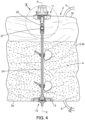
figure 4 est une vue en coupe selon le plan IV-IV du conteneur de lafigure 3 , positionné par rapport à un moteur ; - Les
figures 5A et 5B sont des vues agrandies de l'arbre du dispositif de mélange au niveau du premier palier de lafigure 4 selon deux agencements différents ; et - La
figure 6 est une vue schématique en coupe du conteneur placé dans le dispositif rigide extérieur de contention du récipient-mélangeur en état de fonctionnement, en particulier dans un état assemblé empli.
- There
figure 1 is a perspective view of a possible embodiment of a mixing container according to the invention showing the external rigid containment device; - There
figure 2 is another perspective view of the rigid external containment device of the mixing container of thefigure 1 ; - There
figure 3 is a side view of a container intended to be placed in the external rigid containment device forFigures 1 and 2 ; - There
figure 4 is a sectional view along plan IV-IV of the container of thefigure 3 , positioned relative to an engine; - THE
Figures 5A and 5B are enlarged views of the mixing device shaft at the first bearing of thefigure 4 according to two different arrangements; and - There
figure 6 is a schematic sectional view of the container placed in the external rigid containment device of the mixing vessel in operating condition, in particular in an assembled filled state.
Un récipient-mélangeur 1 selon l'invention est destiné à recevoir un fluide biopharmaceutique C, en vue de son mélange ou, le cas échéant en vue d'une réaction chimique et/ou biologique (ou bioréaction), le récipient-mélangeur 1 étant alors un bioréacteur.A mixing
Le fluide biopharmaceutique C comprend une ou au moins une phase liquide. Le cas échéant, le fluide biopharmaceutique C est réalisé à partir de plusieurs composants dont au moins un est en phase liquide et dont un ou plusieurs peut être en phase solide, tel que de la poudre.The biopharmaceutical fluid C comprises one or at least one liquid phase. Where appropriate, the biopharmaceutical fluid C is made from several components, at least one of which is in the liquid phase and one or more of which may be in the solid phase, such as powder.
Le récipient-mélangeur 1 présente un axe principal XX, vertical. Le récipient-mélangeur 1 comporte d'une part un conteneur 2 et d'autre part un dispositif rigide extérieur de contention 18.The mixing
Comme représenté sur la
Selon une réalisation, le conteneur 2 est à usage unique.According to one embodiment, container 2 is for single use.
Le conteneur 2 peut avoir une capacité allant jusqu'à 5 000 litres, en fonction des besoins et des applications. Le conteneur 2 a cependant de préférence une capacité comprise entre 10 et 500 litres, voire entre 50 et 200 litres.Container 2 can have a capacity of up to 5,000 liters, depending on the needs and applications. Container 2, however, preferably has a capacity of between 10 and 500 liters, or even between 50 and 200 liters.
Les mots « vertical », « horizontal », « supérieur », « inférieur » se réfèrent à la situation dans laquelle le récipient-mélangeur 1, et en particulier le conteneur 2, est dans une position apte à son fonctionnement. Il est entendu toutefois que le récipient-mélangeur 1 et le conteneur 2 peuvent occuper d'autres positions ou avoir d'autres états, par exemple parce qu'ils ne sont pas en fonctionnement. Le mot « vertical » ne doit pas être compris dans un sens étroit, mais dans le sens signifiant du plus haut au plus bas et inversement.The words "vertical", "horizontal", "upper", "lower" refer to the situation in which the mixing
D'autre part, les mots « intérieur » et « extérieur » se réfèrent, respectivement à ce qui se trouve dans l'espace intérieur 4 et hors du conteneur 2.On the other hand, the words "interior" and "exterior" refer, respectively, to what is in the interior space 4 and outside the container 2.
Enfin, les mots « axial » d'une part, « radial » et « transversal » d'autre part, se réfèrent à ce qui s'étend dans ou parallèlement ou sensiblement parallèlement à l'axe principal XX d'une part, et perpendiculairement ou orthogonalement ou sensiblement perpendiculairement ou orthogonalement à l'axe principal XX d'autre part.Finally, the words "axial" on the one hand, "radial" and "transverse" on the other hand, refer to that which extends in or parallel or substantially parallel to the main axis XX on the one hand, and perpendicularly or orthogonally or substantially perpendicularly or orthogonally to the main axis XX on the other hand.
Le récipient-mélangeur 1 peut comporter un ou plusieurs ports 5 traversant d'introduction dans le conteneur 2 du fluide biopharmaceutique C, ou de composants du fluide biopharmaceutique C, coopérant avec un ou plusieurs orifices d'introduction ménagés dans le conteneur 2.The mixing
Le récipient-mélangeur 1 peut comporter également au moins un port 6 traversant de vidange du fluide biopharmaceutique C du conteneur 2, coopérant avec au moins un orifice de vidange ménagé dans le conteneur 2. Le port de vidange 6 est apte à être obturé à chaque fois que nécessaire et au contraire ouvert pour la vidange.The mixing
On entend par « port », un moyen de connexion ou de liaison physique. Un tel port est traversant lorsqu'il s'agit d'assurer une fonction de mise en communication entre l'espace intérieur 4 et l'extérieur du conteneur 2, par exemple pour l'introduction ou la vidange de ce qui doit être placé ou est placé dans le conteneur 2. Un tel port peut également être non traversant lorsqu'il s'agit d'assurer une fonction de maintien d'un organe du récipient-mélangeur.The term “port” means a means of physical connection or link. Such a port is a through port when it is intended to provide a communication function between the interior space 4 and the exterior of the container 2, for example for the introduction or emptying of what must be placed or is placed in the container 2. Such a port may also be a non-through port when it is intended to provide a function of maintaining a member of the mixing container.
Des conduits, poches, réservoirs, le cas échéant souples, peuvent être associé au port d'introduction 5, en communication fluidique et avec une connexion étanche et le cas échéant amovible. De même, des conduits, poches, réservoirs, le cas échéant souples peuvent être associé au port de vidange 6, en communication fluidique et avec une connexion étanche et le cas échéant amovible.Conduits, bags, reservoirs, if necessary flexible, can be associated with the introduction port 5, in fluid communication and with a sealed and if necessary removable connection. Similarly, conduits, bags, reservoirs, if necessary flexible can be associated with the
Dans la réalisation représentée sur les
Le récipient-mélangeur 1 peut également comporter un dispositif d'aération 13 apte à délivrer au fluide biopharmaceutique C une certaine quantité de gaz d'aération. Ce dispositif 13 permet ainsi l'aération de ce qui se trouve dans l'espace intérieur 4 du conteneur 2, qu'il s'agisse du fluide biopharmaceutique C, ou d'une partie de ses composants.The mixing
Le dispositif d'aération 13 peut comprendre un dispositif d'amenée de gaz d'aération 14 ayant au moins un élément tubulaire 14a s'étendant avec communication fluidique depuis l'extérieur du conteneur 2. Au dispositif d'aération 13 qui vient d'être décrit peut être associé fonctionnellement au moins un port d'évacuation de gaz d'aération 36 ménagé dans la partie supérieure 3c de la paroi 3 du conteneur 2. Un tel port d'évacuation de gaz d'aération 36 permet d'évacuer du conteneur 2, vers l'extérieur, le gaz qui n'a pas été mélangé avec le fluide biopharmaceutique C du conteneur 2.The
Le récipient-mélangeur 1 peut, dans certaines réalisations, comporter également d'autres ports connus en soi, par exemple de montage d'un moyen fonctionnel, apte à assurer le maintien d'un organe tel que typiquement la collecte ou la mesure de données, ou la prise d'échantillon aux fins d'analyse.The mixing
Le récipient-mélangeur 1 comporte également un dispositif de mélange 7 du fluide biopharmaceutique C du conteneur 2. Ce dispositif de mélange 7 permet le mélange de ce qui se trouve dans l'espace intérieur 4 du conteneur 2, qu'il s'agisse du fluide biopharmaceutique C, ou d'une partie de ses composants.The mixing
Le dispositif de mélange 7 comprend au moins un arbre 8 descendant, apte à être entraîné, notamment magnétiquement, en rotation par un moteur 9 et à entraîner en rotation au moins un organe de mélange 10. Le ou les organes de mélange 10 sont substantiellement espacés de la partie inférieure 3a et de la partie latérale 3b de la paroi 3 du conteneur 2. Comme représenté sur les
L'arbre 8 est ajustable en longueur. Selon la réalisation représentée sur les figures, l'arbre 8 est ainsi formé de deux parties 24, 25. Une première partie 24 s'étend entre l'extrémité inférieure 8a jusqu'à une zone de liaison intermédiaire 26, tandis que la deuxième partie 25 s'étend depuis la zone de liaison 26 jusqu'à l'extrémité supérieure 8b.The
Comme représenté plus en détails sur les
La première partie 24, notamment l'élément 27, est adapté pour coulisser dans la deuxième partie 25 de l'arbre 8 selon l'axe principal XX. Comme représentée sur les
L'élément 27 est adapté pour coulisser de façon continue dans la fente 28. L'arbre 8 peut donc avoir une longueur ajustable de façon continue et non discrète, par exemple en cas de dilatation de certains éléments du récipient-mélangeur 1 en cours de mélange.The
En outre, du fait que l'élément 27 fait saillie dans la fente 28, la première partie 24 et la deuxième partie 25 de l'arbre 8 sont solidaires en rotation, notamment lorsqu'ils sont soumis à des couples de torsion élevée.Furthermore, because the
En outre, du fait que l'arbre 8 a une longueur ajustable, le moteur 9 peut être fixe par rapport au dispositif extérieur de contention 18, et il n'est pas nécessaire que celui-ci ait un positionnement ajustable, notamment en hauteur afin de placer l'arbre 8 en regard du moteur 9 pour permettre la rotation de l'arbre 8 comme cela sera décrit ci-après.Furthermore, because the
Le conteneur 2 comprend également au moins un premier palier 11, adjacent à la partie supérieure 3c de la paroi 3, avec lequel coopère la partie supérieure 8b de l'arbre 8.The container 2 also comprises at least one
Le premier palier 11 comporte un flasque rigide 16. On entend ici par « flasque », une pièce rigide en forme générale de paroi pleine, au moins sensiblement plate, placée à plat, et destinée au maintien. Ce flasque 16 est fixé de façon rigide et étanche à la partie supérieure 3c de la paroi 3 du conteneur 2.The
Plus précisément, le flasque 16 est formé d'une matière sensiblement rigide, de préférence une matière plastique rigide, en forme de paroi ou de plaquette raccordée au conteneur 2, au centre de la partie supérieure 3c. Ce flasque 16 peut être raccordé à la paroi 3 du conteneur 2 de toute manière appropriée de façon à former un joint rigide et hermétique entre les matières respectives, rigide et flexible du flasque 16 et de la paroi 3.More specifically, the
Selon un premier mode de réalisation, l'arbre 8 du dispositif de mélange 7 est situé tout entier dans l'espace intérieur 4. Ainsi, l'arbre 8 s'étend de façon rectiligne entre une extrémité inférieure 8a et une extrémité supérieure 8b. Lorsque le récipient-mélangeur 1 est dans une position apte à son fonctionnement, l'arbre 8 s'étend de façon verticale suivant l'axe principal XX, l'extrémité inférieure 8a étant située vers la partie inférieure 3a du conteneur 2 tandis que l'extrémité supérieure 8b est située vers la partie supérieure 3c du conteneur 2 en étant reliée au premier palier 11. Le premier palier 11 est alors adapté pour être positionné par rapport au moteur 9 situé à l'extérieur du conteneur 2.According to a first embodiment, the
Selon le premier mode de réalisation représenté par exemple sur les
Le disque rotatif mené 15 est solidaire, notamment en rotation, de l'arbre 8, en particulier de la deuxième partie 25 de l'arbre 8. Par exemple, le disque rotatif mené 15 est fixé à l'extrémité supérieure 8b de l'arbre 8 par vissage d'une extrémité filetée de l'arbre 8 dans une ouverture filetée à l'intérieur du disque rotatif mené 15. D'autres moyens, tels qu'éléments adhésifs, attaches, fixations rapides, verrous, soudage, et similaires, ainsi que la formation du disque rotatif mené 15 directement par moulage avec l'arbre 8 lors de sa fabrication, peuvent être utilisés pour fixer le disque rotatif mené 15 à l'arbre 8, sans limitation.The driven
En outre, le disque rotatif mené 15 est raccordé au premier palier 11, notamment au flasque 16, de manière à permettre au moteur 9 d'agir sur les aimants 17 du disque rotatif mené 15. Ainsi, le flasque 16 est relié à l'arbre 8 dans l'espace intérieur 4 du conteneur 2 par l'intermédiaire du disque rotatif mené 15. En particulier, l'arbre 8 et le disque rotatif mené 15 sont montés mobiles en rotation autour de l'axe principal XX par rapport au premier palier 11, de sorte que le disque rotatif mené 15 peut tourner relativement librement par rapport au flasque 16. A cet effet, on peut prévoir d'inclure des éléments de roulement à billes ou à rouleaux entre le disque rotatif mené 15 et le premier palier 11.Furthermore, the driven rotating
En état de fonctionnement, le premier palier 11 est positionné, en particulier assemblé, par rapport au moteur 9. Le disque rotatif menant 30 du moteur 9 et le disque rotatif mené 15 sont alors disposé en regard l'un de l'autre, de chaque côté du premier palier 11. Il peut être prévu un jeu de battement entre le disque rotatif menant 30 et le premier palier 11, par exemple de l'ordre de 2 millimètres, afin de faciliter la rotation du premier palier 11 par rapport au moteur 9.In operating condition, the
Le premier palier 11, notamment le flasque 16, comprend par exemple une collerette annulaire extérieure 16a comportant un bourrelet radial terminal s'étendant latéralement vers l'extérieur et limitant vers l'intérieur une cavité 16b du flasque 16. Le moteur 9 peut être positionné par rapport au flasque 16 et notamment avec la collerette 16a de manière fixe en translation. En particulier, le disque rotatif menant 30 du moteur 9 est destiné à être disposé dans la cavité 16b du flasque 16 comme cela est représenté sur les
Comme représenté sur la
Selon un deuxième mode de réalisation non représenté sur les figures, l'arbre 8 peut être partiellement situé à l'extérieur du conteneur 2. Selon ce mode de réalisation, l'arbre 8 traverse le conteneur 2, en particulier au niveau du premier palier 11 de façon étanche. Le disque rotatif mené 15 de l'arbre est alors situé à l'extérieur du conteneur 2 et est destiné à coopérer fonctionnellement, notamment magnétiquement, avec le disque rotatif menant 30 du moteur 9.According to a second embodiment not shown in the figures, the
Selon ce mode de réalisation, la zone de liaison 26 de l'arbre 8 peut être située à l'extérieur du conteneur 2. La longueur de l'arbre 8 peut ainsi être facilement ajustée depuis l'extérieur du conteneur 2 par l'utilisateur du récipient-mélangeur 1, ce qui permet d'obtenir un conteneur 2 simple d'utilisation et économique à réaliser. En outre, la zone de liaison 26 est alors plus facile d'accès, ce qui permet de faciliter sa stérilisation avant utilisation du conteneur 2.According to this embodiment, the connecting
Le récipient-mélangeur 1 peut comporter également, en raison de la nature flexible du conteneur 2, un dispositif rigide extérieur de contention 18 pour une contention du conteneur 2 empli de son fluide biopharmaceutique C pendant le remplissage, le mélange et la vidange.The mixing
Le dispositif rigide extérieur de contention 18 comprend une paroi de fond 19 et une paroi périphérique 20 délimitant un logement dans lequel est placé de façon amovible le conteneur 2. La paroi de fond 19 a par exemple une forme de calotte arrondie, par exemple hémisphérique ou pseudo hémisphérique, Toutefois, le dispositif rigide extérieur de contention 18 peut avoir toute autre forme, telle que cylindrique, parallèpipédique ou autres.The rigid
La partie inférieure 3a de la paroi 3 du conteneur 2 repose sur la paroi de fond 19, tandis que la partie latérale 3b de la paroi 3 du conteneur 2 vient s'appliquer, lorsque le conteneur 2 est empli de fluide biopharmaceutique C, contre la paroi périphérique 20. Le dispositif rigide extérieur de contention 18 est généralement de géométrie, forme et et/ou dimension identiques au conteneur 2, afin de réduire les sollicitations ou les contraintes mécaniques sur la paroi 3 du conteneur 2.The
Le dispositif rigide extérieur de contention 18 peut comporter une ouverture d'accès 21 afin de permettre la mise en place et l'enlèvement du conteneur 2. Le cas échéant, le dispositif rigide extérieur de contention 18 comporte un moyen de fermeture, tels que des portes, afin de permettre alternativement l'ouverture ou la fermeture de l'ouverture d'accès 21.The rigid
Selon une réalisation, le dispositif rigide extérieur de contention 18 comporte d'autres ouvertures pour introduire le fluide biopharmaceutique C ou les composants du fluide biopharmaceutique C et vidanger le fluide biopharmaceutique C, ou pour accéder aux différents éléments du conteneur 2 qui doivent être accessibles pour l'utilisation.According to one embodiment, the external
Le moteur 9 est avantageusement placé au-dessus du dispositif rigide extérieur de contention 18, de façon fixe. Comme représenté plus particulièrement sur les
Selon une réalisation, le dispositif rigide extérieur de contention 18 comporte également un dispositif de chauffage et/ou de refroidissement destiné au chauffage et/ou au refroidissement du fluide biopharmaceutique C du conteneur 2. Dans ce cas, le dispositif rigide extérieur de contention 18 et/ou le conteneur 2 sont réalisés en un matériau présentant une certaine conductivité thermique, de manière que la mise en œuvre du dispositif de chauffage et/ou de refroidissement permette le chauffage et/ou le refroidissement du fluide biopharmaceutique C. Dans ce cas, et le cas échéant, il est également prévu un dispositif de contrôle de la température du contenu dans le conteneur 2 et un dispositif de commande du dispositif de chauffage et/ou de refroidissement. Un tel dispositif de contrôle de la température peut être porté par un ou des ports prévus à cet effet.According to one embodiment, the external
Le conteneur 2 peut comprendre un unique premier palier 11, pour être positionné par rapport au moteur 9. Toutefois, en variante, le conteneur 2 peut en outre comprendre un second palier 12, adjacent à la partie inférieure 3a de la paroi 3, avec lequel coopère la partie inférieure 8a de l'arbre 8. De la même façon que le premier palier 11, le second palier 12 est raccordé à la paroi 3 du conteneur 2 pour former un joint rigide et étanche avec la partie inférieure 3a de la paroi 3. A cet effet, le second palier 12 comprend un flasque (ce terme devant être compris comme précédemment) fixé de façon rigide et étanche à la partie inférieure 3a de la paroi 3 du conteneur 2.The container 2 may comprise a single
Le conteneur 2 est alors raccordé au niveau du second palier 12 au dispositif extérieur de contention 18. Selon le premier mode de réalisation décrit ci-dessus dans lequel l'arbre 8 du dispositif de mélange 7 est situé tout entier dans l'espace intérieur 4, il est ainsi possible d'ajuster la taille du conteneur 2 en ajustant la longueur de l'arbre 8 qui s'étend entre le premier palier 11 et le second palier 12.The container 2 is then connected at the
Le conteneur 2 peut se trouver dans trois états distincts en relation avec le dispositif rigide extérieur de contention 18 :
- un état désassemblé vide, dans lequel le conteneur 2 est désassemblé du dispositif rigide extérieur de
contention 18 et n'est pas positionné par rapport au moteur 9. Dans cet état, le conteneur 2, qui est flexible dans son ensemble, alors qu'il est vide du fluide biopharmaceutique C, peut être disposé de façon aplatie sur lui-même. Cet état est tout particulièrement utile pour le stockage ou le transport ; - un état assemblé vide, dans lequel le conteneur 2 est assemblé au dispositif rigide extérieur de
contention 18, le conteneur 2 étant vide du fluide biopharmaceutique C. Dans cet état, le conteneur 2 est disposé dans le logement du dispositif decontention 18 en reposant sur la paroi de fond 19. On entend notamment par « assemblage », le fait que le conteneur 2 interagit fonctionnellement avec le moteur 9. Toutefois, un tel assemblage n'est pas limité à un contact direct entre le conteneur 2 et le moteur 9, ces éléments pouvant être assemblés selon l'invention tout en étant espacés l'un de l'autre, par exemple dans le cadre d'un entrainement magnétique ; et - et, enfin, un état assemblé partiellement ou complètement empli, dans lequel le conteneur 2 est assemblé au dispositif rigide extérieur de
contention 18 et positionné par rapport au moteur 9, le conteneur 2 étant empli de fluide biopharmaceutique C. Dans cet état, le récipient-mélangeur 1 est apte à fonctionner afin de permettre le mélange du fluide biopharmaceutique C.
- an empty disassembled state, in which the container 2 is disassembled from the external
rigid containment device 18 and is not positioned relative to the motor 9. In this state, the container 2, which is flexible as a whole, while empty of the biopharmaceutical fluid C, can be arranged flattened on itself. This state is particularly useful for storage or transport; - an empty assembled state, in which the container 2 is assembled to the external
rigid containment device 18, the container 2 being empty of the biopharmaceutical fluid C. In this state, the container 2 is arranged in the housing of thecontainment device 18 while resting on thebottom wall 19. The term “assembly” is understood in particular to mean the fact that the container 2 functionally interacts with the motor 9. However, such an assembly is not limited to direct contact between the container 2 and the motor 9, these elements being able to be assembled according to the invention while being spaced from each other, for example in the context of a magnetic drive; and - and, finally, a partially or completely filled assembled state, in which the container 2 is assembled to the external
rigid containment device 18 and positioned relative to the motor 9, the container 2 being filled with biopharmaceutical fluid C. In this state, the mixingcontainer 1 is able to operate in order to allow the mixing of the biopharmaceutical fluid C.
On décrit ci-après le procédé d'assemblage d'un récipient-mélangeur 1 selon le premier mode de réalisation, notamment pour passer entre les différents états du conteneur 2 décrits ci-dessus.The method of assembling a mixing
On part d'un récipient-mélangeur 1 dont le conteneur 2 est dans un état désassemblé du dispositif rigide extérieur de contention 18, ainsi que vide de fluide biopharmaceutique C et disposé de façon plus ou moins aplatie sur lui-même.We start with a mixing
On dispose le conteneur 2 dans le logement au dispositif rigide extérieur de contention, en reposant sur sa paroi de fond 19.The container 2 is placed in the housing with the external rigid containment device, resting on its
On raccorde le second palier 12 du conteneur 2 avec le dispositif rigide extérieur de contention 18, par exemple avec une ouverture 29 située au centre de la paroi de fond 19.The
On positionne ensuite le premier palier 11 du conteneur 2 par rapport au moteur 9. On amène donc la poche 3 du conteneur 2 au niveau du moteur 9.The
L'arbre 8 se trouve alors dans une position au moins partiellement rétractée. Du fait que l'arbre 8 soit ajustable en longueur, il est possible tout d'abord de placer l'extrémité supérieure 8b, notamment le premier palier 11, écarté du moteur 9. Le premier palier 11 peut notamment être placé au voisinage immédiat du moteur 9, par exemple à une distance du moteur 9 inférieure à la longueur lf de la fente 28. Le disque rotatif mené 15 est alors situé face au moteur 9. On augmente ensuite la longueur de l'arbre 8 afin que le premier palier 11 soit positionné en regard du moteur 9, notamment raccordé sans frottement et avec un jeu de battement entre le disque rotatif menant 30 du moteur 9 et le premier palier 11, de sorte que le moteur 9 peut tourner facilement.The
Afin d'ajuster la longueur de l'arbre 8, le coulissement des deux parties 24, 25 de l'arbre 8 entre elles peut être réalisé manuellement ou avec tout autre outil permettant un tel coulissement. Ainsi, il n'est pas nécessaire lors de connexion du premier palier 11 avec le moteur 9, de faire varier la position du moteur 9. Le conteneur 2 est ainsi assemblé plus facilement et de façon optimale avec le dispositif rigide extérieur de contention 18.In order to adjust the length of the
Le moteur 9 est raccordé avec la collerette 16a du flasque 16 de façon solidaire en translation grâce à la pince 22 (menotte tri-clamp) faisant fonction de bride. Ainsi agencé, le disque rotatif menant du moteur 9 est apte à entrainer en rotation le disque rotatif mené 15, et donc l'arbre 8 du dispositif de mélange 7. La
Alternativement, il est possible de connecter le premier palier 11 du conteneur 2 avec le moteur 9 avant de raccorder le second palier 12 avec le dispositif rigide extérieur de contention 18.Alternatively, it is possible to connect the
On introduit dans le conteneur 2 le fluide biopharmaceutique C, notamment grâce au port d'introduction 5.The biopharmaceutical fluid C is introduced into the container 2, in particular via the introduction port 5.
Enfin, on met en œuvre le dispositif de mélange 7 pour agiter le fluide biopharmaceutique C du conteneur 2 se trouvant dans l'espace intérieur 4. Le cas échéant, la longueur de l'arbre s'adapte pour garantir le positionnement relatif optimal du moteur 9 et du premier palier 11.Finally, the mixing device 7 is used to agitate the biopharmaceutical fluid C of the container 2 located in the interior space 4. If necessary, the length of the shaft is adapted to ensure the optimal relative positioning of the motor 9 and the
Par ailleurs, dans le cadre d'un procédé de bioréaction on met en œuvre le dispositif d'aération 13 pour délivrer au contenu du conteneur 2 se trouvant dans l'espace intérieur 4, une certaine quantité de gaz d'aération. L'agitation et l'aération sont réalisées au moins partiellement simultanément, le cas échéant, totalement simultanément.Furthermore, in the context of a bioreaction process, the
Suite au mélange du fluide biopharmaceutique C et à sa vidange, notamment par le port de vidange 6, on désassemble le conteneur 2 du dispositif rigide extérieur de contention 18. On jette alors le conteneur 2, celui-ci étant à usage unique.Following the mixing of the biopharmaceutical fluid C and its emptying, in particular via the emptying
Le procédé décrit ci-dessus peut être réalisé partiellement, les étapes décrites ci-dessus pouvant être réalisée indépendamment l'une de l'autre. En particulier, le conteneur 2 peut être disposé dans le dispositif rigide extérieur de contention 18 alors qu'il est déjà empli de fluide biopharmaceutique C.The method described above can be carried out partially, the steps described above being able to be carried out independently of one another. In particular, the container 2 can be placed in the external
Bien évidemment, l'invention n'est pas limitée aux modes de réalisation décrits précédemment et fournis uniquement à titre d'exemple. Elle englobe diverses modifications, formes alternatives et autres variantes que pourra envisager l'homme du métier dans le cadre de la présente invention telle que revendiquée et notamment toutes combinaisons des différents modes de fonctionnement décrits précédemment, pouvant être pris séparément ou en association.Obviously, the invention is not limited to the embodiments described above and provided solely as examples. It encompasses various modifications, alternative forms and other variants that may be envisaged by those skilled in the art within the framework of the present invention as claimed and in particular all combinations of the different operating modes described above, which may be taken separately or in combination.
Claims (11)
- A method for assembling a mixer-container (1) intended to receive a biopharmaceutical fluid (C) in order to mix it, wherein:- a container (2) is provided, having a flexible wall (3) defining an inner space (4) suitable for filling with biopharmaceutical fluid (C), the container (2) comprising:o a mixing device (7) having a shaft (8) having an adjustable length along a main axis (XX), the shaft (8) extending rectilinearly between a lower end (8a) and an upper end (8b),o a first bearing (11) attached to the wall (3), the shaft (8) extending at least into the inner space (4) from the first bearing (11),- a rigid outer containment device (18) of the container (2) is provided,- a drive motor (9) is provided, located outside the container (2), the motor (9) being suitable for rotating the shaft (8) of the mixing device (7),- the container (2) is placed in the rigid outer containment device (18), the rigid outer containment device (18) comprising a bottom wall (19) and a peripheral wall (20) defining a housing suitable for receiving the container (2), the flexible wall (3) of the container (2) being arranged on the bottom wall (19) of the rigid outer containment device (18), and- knowing that the position of the motor is fixed relative to the rigid outer containment device (18) and that the container (2) is already placed in the rigid outer containment device (18), the length of the shaft (8) along the main axis (XX) is adjusted by arranging the shaft (8) facing the motor (9), on the side of the upper end (8b), in order to enable the motor (9) to rotate the shaft (8), the shaft (8) extending vertically along the main axis (XX) with the lower end (8a) located towards a lower part (3a) of the container (2) while the upper end (8b) is located towards an upper part (3c) of the container (2), being connected to the first bearing (11),and wherein the shaft (8) has a first part (24) and a second part (25) which are movable in translation relative to one another along the main axis (XX), the first part (24) comprising an element (27) suitable for sliding in a rectilinear slot (28) of the second part (25) of the shaft by adjusting the length of the shaft (8), and wherein the first bearing (11) is placed in the immediate vicinity of the motor (9), at a distance from the motor (9) less than the length (If) of the rectilinear slot (28).
- The method according to claim 1, wherein the motor (9) is suitable for rotating the shaft (8), by magnetic rotating of said shaft (8), the first bearing (11) having a rigid flange (16) rigidly and sealingly fixed to an upper part (3c) of the wall (3) of the container (2),
and wherein the upper part (3c) of the flexible wall (3) is brought to the motor (9) in order that a rotary drive disc (30) belonging to the motor (9) and located outside the container (2) is arranged in a cavity (16b) of the flange (16), the rotary drive disc (30) operatively engaging with a rotary driven disc (15) attached to the shaft (8) at the upper end (8b), the rotary driven disc (15) comprising a plurality of magnets (17) and being suitable for turning relative to the flange (16). - The method according to claim 1 or 2, wherein the container (2) is in a disassembled state, empty of biopharmaceutical fluid (C), when it is placed in the rigid outer containment device (18).
- The method according to claim 1, 2 or 3, wherein the length of the shaft (8) is adjustable on a stroke substantially corresponding to the axial size of the motor (9).
- The method according to any one of claims 1 to 4, wherein the shaft (8) is entirely located in the inner space (4) and the length of the shaft (8) along the main axis (XX) is adjusted by positioning the first bearing (11) facing the motor (9) in order to allow the motor (9) to rotate the shaft (8).
- The method according to any one of the preceding claims, wherein the container (2) also comprises a second bearing (12) attached to the wall (3) and the second bearing (12) is connected to the rigid outer containment device (18) after having placed, via an access opening (21), the container (2) in the rigid outer containment device (18), the access opening (21) being provided in the peripheral wall (20) and enabling the placing and removal of the container (2).
- The method according to any one of the preceding claims, wherein the container (2) provided with a drainage port (6) is removably placed in the rigid outer containment device (18), said container (2) being disposable.
- A container-mixer (1) intended to be assembled by the assembly method according to any one of the preceding claims, comprising:- said container (2) for which the inner space (4) defined by the flexible wall (3) is suitable for being filled with biopharmaceutical fluid (C), the container (2) comprising:o the mixing device (7) having the shaft (8) which extends rectilinearly and the length of which is adjustable along a main axis (XX),o the first bearing (11) from which the shaft (8) extends into the inner space (4),- the drive motor (9) located outside the container (2), the motor (9) being suitable for rotating the shaft (8) of the mixing device (7), and- the rigid outer containment device (18), the bottom wall (19) and the peripheral wall (20) of which define the housing suitable for receiving the container (2),characterised in that the motor (9) is fixed relative to the rigid outer containment device (18), the length of the shaft (8) being adjustable along the main axis (XX) in order that the shaft (8) extends vertically along the main axis (XX) having said lower end (8a) located towards a lower part (3a) of the container (2) and said upper end (8b) located towards the upper part (3c) of the container (2), being connected to the first bearing (11),wherein the shaft (8) of adjustable length extends between the first bearing (11) and a second bearing (12), each of the first bearing (11) and second bearing (12) being fixed to the flexible wall (3) of said container (2),and wherein the shaft (8) comprises a first part (24) and a second part (25), movable in translation relative to one another along the main axis (XX), the first part comprising an element (27) suitable for sliding in a rectilinear slot (28) of the second part (25) of the shaft (8).
- The container-mixer (1) according to claim 8, wherein the motor (9) is suitable for enabling the magnetic driving of the shaft (8) and comprises a rotary drive disc (30) located outside of the container (2), the rotary drive disc (30) operatively engaging with a rotary driven disc (15) attached to the shaft (8).
- The container-mixer (1) according to claim 9, wherein the first bearing (11) has a rigid flange (16) rigidly and sealingly fixed to an upper part (3c) of the wall (3) of the container (2), the flange (16) comprising an outer annular collar (16a) with which the motor (9) is connected to the container (2), and wherein the flange (16) is connected to the shaft (8) in the inner space (4) of the container (2) by means of the rotary driven disc (15), the rotary driven disc (15) being able to turn relatively freely relative to the flange (16).
- The container-mixer (1) according to any one of claims 8 to 10, wherein the shaft (8) supports and drives at least one mixing member (10) suitable for mixing the biopharmaceutical fluid (C) located in the inner space (4).
Applications Claiming Priority (2)
| Application Number | Priority Date | Filing Date | Title |
|---|---|---|---|
| FR1557500A FR3039776B1 (en) | 2015-08-03 | 2015-08-03 | METHOD FOR ASSEMBLING A CONTAINER-MIXER COMPRISING A TELESCOPIC TREE |
| PCT/FR2016/052017 WO2017021653A1 (en) | 2015-08-03 | 2016-08-02 | Mixer-container and method for assembling a mixer-container including a telescopic shaft |
Publications (2)
| Publication Number | Publication Date |
|---|---|
| EP3331637A1 EP3331637A1 (en) | 2018-06-13 |
| EP3331637B1 true EP3331637B1 (en) | 2025-01-22 |
Family
ID=54783750
Family Applications (1)
| Application Number | Title | Priority Date | Filing Date |
|---|---|---|---|
| EP16757705.5A Active EP3331637B1 (en) | 2015-08-03 | 2016-08-02 | Mixing receptacle and process for assembling a mixing receptacle comprising a telescopic shaft |
Country Status (5)
| Country | Link |
|---|---|
| US (2) | US10456761B2 (en) |
| EP (1) | EP3331637B1 (en) |
| CN (2) | CN107921387B (en) |
| FR (1) | FR3039776B1 (en) |
| WO (1) | WO2017021653A1 (en) |
Families Citing this family (28)
| Publication number | Priority date | Publication date | Assignee | Title |
|---|---|---|---|---|
| FR3039776B1 (en) * | 2015-08-03 | 2017-08-25 | Sartorius Stedim Fmt Sas | METHOD FOR ASSEMBLING A CONTAINER-MIXER COMPRISING A TELESCOPIC TREE |
| US11110418B2 (en) * | 2016-01-19 | 2021-09-07 | Kiinns Foodtech Ltd. | Internal shield system for fluids and solids processing devices and uses thereof |
| CN106823927B (en) * | 2017-03-24 | 2019-06-11 | 武汉华星光电技术有限公司 | A kind of agitating device and photoresist bucket of processing photoresist deposition |
| CN109503217A (en) * | 2018-12-10 | 2019-03-22 | 苏州臻裕生物科技有限公司 | A kind of waste and strain agitating device |
| CN112168324B (en) * | 2019-07-04 | 2022-09-06 | 北京中科盛康科技有限公司 | Bone cement stirrer |
| US11998880B2 (en) * | 2020-09-01 | 2024-06-04 | Global Life Sciences Solutions Usa Llc | Collapsible agitator assembly for a bioprocessing system |
| FR3122094B1 (en) * | 2021-04-23 | 2023-04-14 | Sartorius Stedim Fmt Sas | Method for sterilizing an assembly comprising at least one single-use device for biopharmaceutical fluid |
| CN113509875A (en) * | 2021-05-10 | 2021-10-19 | 清华大学 | Electric drive magnetic force rotating stirring device |
| CN114904307B (en) * | 2022-04-29 | 2023-06-13 | 天津建工城市建设发展有限公司 | Pulping pool |
| US12213617B2 (en) | 2022-05-13 | 2025-02-04 | Sharkninja Operating Llc | Flavored beverage carbonation process |
| US12096880B2 (en) | 2022-05-13 | 2024-09-24 | Sharkninja Operating Llc | Flavorant for beverage carbonation system |
| US11751585B1 (en) | 2022-05-13 | 2023-09-12 | Sharkninja Operating Llc | Flavored beverage carbonation system |
| WO2023216231A1 (en) | 2022-05-13 | 2023-11-16 | Sharkninja Operating Llc | Agitator for a carbonation system |
| US11647860B1 (en) | 2022-05-13 | 2023-05-16 | Sharkninja Operating Llc | Flavored beverage carbonation system |
| US12005404B2 (en) | 2022-08-22 | 2024-06-11 | Sharkninja Operating Llc | Beverage carbonation system flow control |
| US12539500B2 (en) | 2022-08-31 | 2026-02-03 | Sharkninja Operating Llc | Additive containers |
| US12103840B2 (en) | 2022-11-17 | 2024-10-01 | Sharkninja Operating Llc | Ingredient container with sealing valve |
| US11634314B1 (en) | 2022-11-17 | 2023-04-25 | Sharkninja Operating Llc | Dosing accuracy |
| US11745996B1 (en) | 2022-11-17 | 2023-09-05 | Sharkninja Operating Llc | Ingredient containers for use with beverage dispensers |
| US12084334B2 (en) | 2022-11-17 | 2024-09-10 | Sharkninja Operating Llc | Ingredient container |
| US11738988B1 (en) | 2022-11-17 | 2023-08-29 | Sharkninja Operating Llc | Ingredient container valve control |
| USD1091308S1 (en) | 2022-12-23 | 2025-09-02 | Sharkninja Operating Llc | Ingredient container |
| USD1092208S1 (en) | 2022-12-23 | 2025-09-09 | Sharkninja Operating Llc | Cap of ingredient container |
| US11871867B1 (en) | 2023-03-22 | 2024-01-16 | Sharkninja Operating Llc | Additive container with bottom cover |
| US11925287B1 (en) | 2023-03-22 | 2024-03-12 | Sharkninja Operating Llc | Additive container with inlet tube |
| US12116257B1 (en) | 2023-03-22 | 2024-10-15 | Sharkninja Operating Llc | Adapter for beverage dispenser |
| US12005408B1 (en) | 2023-04-14 | 2024-06-11 | Sharkninja Operating Llc | Mixing funnel |
| WO2024254837A1 (en) | 2023-06-16 | 2024-12-19 | Sharkninja Operating Llc | Carbonation mixing nozzles |
Citations (1)
| Publication number | Priority date | Publication date | Assignee | Title |
|---|---|---|---|---|
| WO2013151733A1 (en) * | 2012-04-06 | 2013-10-10 | Hyclone Laboratories, Inc. | Fluid mixing system with flexible drive line and foldable impeller |
Family Cites Families (29)
| Publication number | Priority date | Publication date | Assignee | Title |
|---|---|---|---|---|
| DE2017472A1 (en) * | 1970-04-11 | 1971-11-04 | Roehm Gmbh | Magnetic agitator for small vessels |
| US7153021B2 (en) * | 2003-03-28 | 2006-12-26 | Hyclone Laboratories, Inc. | Container systems for mixing fluids with a magnetic stir bar |
| SE531572C2 (en) * | 2006-04-05 | 2009-05-26 | Millipore Ab | Disposable unit for process products |
| DE102006021984B4 (en) * | 2006-05-10 | 2013-05-08 | Sartorius Stedim Biotech Gmbh | bioreactor |
| FR2921905B1 (en) * | 2007-10-04 | 2012-09-28 | Sartorius Stedim Biotech | CONTAINER FOR PROCESSING AND / OR CONTROLLING PRODUCTS COMPRISING A CHAMBER FOR PROTECTING MEANS OF PROCESSING AND / OR CONTROLLING THESE PRODUCTS, AND CONTAINER COMPRISING SUCH A CONTAINER |
| US7832922B2 (en) * | 2007-11-30 | 2010-11-16 | Levitronix Gmbh | Mixing apparatus and container for such |
| DE102007060291B4 (en) * | 2007-12-12 | 2011-04-28 | Sartorius Stedim Biotech Gmbh | Container arrangement with a container with flexible wall |
| DE102007061664B4 (en) * | 2007-12-18 | 2009-11-19 | Sartorius Stedim Biotech Gmbh | Container with flexible wall |
| US9044718B2 (en) * | 2008-03-19 | 2015-06-02 | Sartorius Stedim Biotech Gmbh | Mixing vessel |
| FR2929253B1 (en) * | 2008-03-28 | 2013-09-13 | Sartorius Stedim Biotech Sa | RIGID FRAME FOR 3D CONTAINER CONTAINING AT LEAST PARTIALLY DEFORMABLE |
| EP2402073B1 (en) * | 2008-04-17 | 2013-01-23 | Sartorius Stedim Biotech GmbH | Flexible bag with a mixing device |
| FR2932697B1 (en) * | 2008-06-20 | 2011-06-10 | Fillon Technologies | AGITATION DEVICE AND METHOD OF ADJUSTING |
| FR2933881B1 (en) * | 2008-07-16 | 2011-05-27 | Sartorius Stedim Biotech Sa | MIXING IN A CONTAINER OF A CONTENT HAVING A BASE COMPONENT AND A MIXING COMPONENT |
| DE102008058338B4 (en) * | 2008-11-20 | 2010-11-11 | Sartorius Stedim Biotech Gmbh | Stirrer for bioreactor |
| US8851785B1 (en) | 2009-11-17 | 2014-10-07 | Trw Automotive U.S. Llc | Ball joint |
| US8960486B2 (en) * | 2010-06-16 | 2015-02-24 | Life Technologies Corporation | Fluid mixing system with hangers |
| FR2962224B1 (en) * | 2010-07-02 | 2013-05-10 | Sartorius Stedim Biotech Sa | SENSOR DEVICE OF A PARAMETER RELATED TO AN ELECTRIC PHENOMENON OF A BIOPHARMACEUTICAL CONTENT AND A BIOPHARMACEUTICAL CONTAINER HAVING SUCH A SENSOR DEVICE. |
| FR2969506B1 (en) * | 2010-12-22 | 2013-02-15 | Sartorius Stedim Biotech Sa | MIXING THE CONTENTS OF A FLEXIBLE CONTAINER FOR BIOPHARMACEUTICAL USE. |
| US10435658B2 (en) * | 2011-10-25 | 2019-10-08 | Life Technologies Corporation | Fluid mixing systems with adjustable mixing element |
| FR2985518B1 (en) * | 2012-01-05 | 2014-02-07 | Sartorius Stedim Biotech Sa | CONTAINER FOR BIOPHARMACEUTICAL CONTENT. |
| US9700857B1 (en) * | 2012-03-23 | 2017-07-11 | Life Technologies Corporation | Fluid mixing system with drive shaft steady support |
| WO2014116165A1 (en) * | 2013-01-23 | 2014-07-31 | Ge Healthcare Bio-Sciences Ab | Magnetic agitator mixing system and an agitator mixing stand |
| DE102013002091B3 (en) * | 2013-02-05 | 2014-05-28 | Sartorius Stedim Biotech Gmbh | Container, transport device, use and method |
| DE102013106680B3 (en) * | 2013-06-26 | 2014-08-14 | Sartorius Stedim Biotech Gmbh | container |
| CN110172406B (en) * | 2013-09-16 | 2023-08-08 | 豪夫迈·罗氏有限公司 | Bioreactors with multiple or adjustable position agitator designs |
| WO2015148187A1 (en) * | 2014-03-22 | 2015-10-01 | Life Technologies Corporation | Impeller assemblies for fluid processing systems |
| FR3039776B1 (en) * | 2015-08-03 | 2017-08-25 | Sartorius Stedim Fmt Sas | METHOD FOR ASSEMBLING A CONTAINER-MIXER COMPRISING A TELESCOPIC TREE |
| DE102016003136B4 (en) * | 2016-03-15 | 2024-01-11 | Sartorius Stedim Biotech Gmbh | Device and method for holding a disposable container |
| EP3241608B1 (en) * | 2016-05-02 | 2020-04-08 | Levitronix GmbH | Mixing device and disposable device for such a mixing device |
-
2015
- 2015-08-03 FR FR1557500A patent/FR3039776B1/en active Active
-
2016
- 2016-08-02 CN CN201680047799.7A patent/CN107921387B/en active Active
- 2016-08-02 US US15/750,048 patent/US10456761B2/en active Active
- 2016-08-02 EP EP16757705.5A patent/EP3331637B1/en active Active
- 2016-08-02 CN CN202110035430.7A patent/CN112844138B/en active Active
- 2016-08-02 WO PCT/FR2016/052017 patent/WO2017021653A1/en not_active Ceased
-
2019
- 2019-07-08 US US16/504,612 patent/US10702838B2/en active Active
Patent Citations (1)
| Publication number | Priority date | Publication date | Assignee | Title |
|---|---|---|---|---|
| WO2013151733A1 (en) * | 2012-04-06 | 2013-10-10 | Hyclone Laboratories, Inc. | Fluid mixing system with flexible drive line and foldable impeller |
Also Published As
| Publication number | Publication date |
|---|---|
| US10702838B2 (en) | 2020-07-07 |
| FR3039776A1 (en) | 2017-02-10 |
| CN112844138B (en) | 2022-11-01 |
| US20190329197A1 (en) | 2019-10-31 |
| CN107921387B (en) | 2021-02-09 |
| US10456761B2 (en) | 2019-10-29 |
| US20180221838A1 (en) | 2018-08-09 |
| WO2017021653A1 (en) | 2017-02-09 |
| EP3331637A1 (en) | 2018-06-13 |
| CN112844138A (en) | 2021-05-28 |
| CN107921387A (en) | 2018-04-17 |
| FR3039776B1 (en) | 2017-08-25 |
Similar Documents
| Publication | Publication Date | Title |
|---|---|---|
| EP3331637B1 (en) | Mixing receptacle and process for assembling a mixing receptacle comprising a telescopic shaft | |
| EP2408901B1 (en) | Mixing container comprising a shaft bearing in the upper part | |
| EP2254687B1 (en) | Mixing vessel | |
| EP0553190B1 (en) | Mixing bowl for a planetary centrifugal mixer and mixer receiving such bowls | |
| EP2259980B1 (en) | Large liquid container for biopharmaceutical applications | |
| EP2222268B1 (en) | Connection of an accessory to a vessel | |
| EP2205496B1 (en) | Vessel for processing a biopharmaceutical product including protection means, device and method | |
| EP1855541A1 (en) | Simplified ice-cream maker | |
| FR2865457A1 (en) | METHOD OF ASSEMBLING A CAP WITH A RECEPTION CONTAINER, CAP FOR THIS METHOD AND RECEIVING CONTAINER AND RECEPTION SYSTEM FORMED THEREFROM | |
| EP2585576B1 (en) | Petri dish comprising locking means for the purpose of forming a stack | |
| EP2800806B1 (en) | Container for biopharmaceutical content | |
| EP0328590B1 (en) | Auxiliary work bowl for kitchen mixer | |
| EP2588591B1 (en) | Device for sensing a parameter related to an electrical phenomenon of a biopharmaceutical content and biopharmaceutical container comprising such a sensing device | |
| WO2011058272A1 (en) | Container for fluid comprising a bag for containing said fluid and related barrel | |
| EP1868901A1 (en) | Multiple pivoting flask | |
| EP3651889B1 (en) | Fluid agitating device and lid equipped with such an agitating device | |
| EP1050335A1 (en) | Spherical mixer | |
| EP1571103B1 (en) | Dispensing device | |
| FR2587917A1 (en) | Pneumatic stirrer | |
| EP4522342A1 (en) | Fluid product dispenser | |
| JP4958644B2 (en) | Mixing deaerator |
Legal Events
| Date | Code | Title | Description |
|---|---|---|---|
| STAA | Information on the status of an ep patent application or granted ep patent |
Free format text: STATUS: UNKNOWN |
|
| STAA | Information on the status of an ep patent application or granted ep patent |
Free format text: STATUS: THE INTERNATIONAL PUBLICATION HAS BEEN MADE |
|
| PUAI | Public reference made under article 153(3) epc to a published international application that has entered the european phase |
Free format text: ORIGINAL CODE: 0009012 |
|
| STAA | Information on the status of an ep patent application or granted ep patent |
Free format text: STATUS: REQUEST FOR EXAMINATION WAS MADE |
|
| 17P | Request for examination filed |
Effective date: 20180124 |
|
| AK | Designated contracting states |
Kind code of ref document: A1 Designated state(s): AL AT BE BG CH CY CZ DE DK EE ES FI FR GB GR HR HU IE IS IT LI LT LU LV MC MK MT NL NO PL PT RO RS SE SI SK SM TR |
|
| AX | Request for extension of the european patent |
Extension state: BA ME |
|
| DAV | Request for validation of the european patent (deleted) | ||
| DAX | Request for extension of the european patent (deleted) | ||
| STAA | Information on the status of an ep patent application or granted ep patent |
Free format text: STATUS: EXAMINATION IS IN PROGRESS |
|
| 17Q | First examination report despatched |
Effective date: 20210707 |
|
| REG | Reference to a national code |
Ref country code: DE Ref legal event code: R079 Free format text: PREVIOUS MAIN CLASS: B01F0007000000 Ipc: B01F0023231000 Ref document number: 602016091010 Country of ref document: DE |
|
| RIC1 | Information provided on ipc code assigned before grant |
Ipc: B01F 35/513 20220101ALI20240328BHEP Ipc: B01F 33/453 20220101ALI20240328BHEP Ipc: B01F 27/91 20220101ALI20240328BHEP Ipc: B01F 27/88 20220101ALI20240328BHEP Ipc: B01F 27/213 20220101ALI20240328BHEP Ipc: B01F 27/2124 20220101ALI20240328BHEP Ipc: B01F 27/191 20220101ALI20240328BHEP Ipc: B01F 23/233 20220101ALI20240328BHEP Ipc: B01F 23/231 20220101AFI20240328BHEP |
|
| GRAP | Despatch of communication of intention to grant a patent |
Free format text: ORIGINAL CODE: EPIDOSNIGR1 |
|
| STAA | Information on the status of an ep patent application or granted ep patent |
Free format text: STATUS: GRANT OF PATENT IS INTENDED |
|
| INTG | Intention to grant announced |
Effective date: 20240510 |
|
| GRAJ | Information related to disapproval of communication of intention to grant by the applicant or resumption of examination proceedings by the epo deleted |
Free format text: ORIGINAL CODE: EPIDOSDIGR1 |
|
| STAA | Information on the status of an ep patent application or granted ep patent |
Free format text: STATUS: EXAMINATION IS IN PROGRESS |
|
| GRAP | Despatch of communication of intention to grant a patent |
Free format text: ORIGINAL CODE: EPIDOSNIGR1 |
|
| STAA | Information on the status of an ep patent application or granted ep patent |
Free format text: STATUS: GRANT OF PATENT IS INTENDED |
|
| INTC | Intention to grant announced (deleted) | ||
| INTG | Intention to grant announced |
Effective date: 20240909 |
|
| RAP3 | Party data changed (applicant data changed or rights of an application transferred) |
Owner name: SARTORIUS STEDIM FMT |
|
| GRAS | Grant fee paid |
Free format text: ORIGINAL CODE: EPIDOSNIGR3 |
|
| GRAA | (expected) grant |
Free format text: ORIGINAL CODE: 0009210 |
|
| STAA | Information on the status of an ep patent application or granted ep patent |
Free format text: STATUS: THE PATENT HAS BEEN GRANTED |
|
| RAP3 | Party data changed (applicant data changed or rights of an application transferred) |
Owner name: SARTORIUS STEDIM FMT |
|
| P01 | Opt-out of the competence of the unified patent court (upc) registered |
Free format text: CASE NUMBER: APP_63237/2024 Effective date: 20241128 |
|
| AK | Designated contracting states |
Kind code of ref document: B1 Designated state(s): AL AT BE BG CH CY CZ DE DK EE ES FI FR GB GR HR HU IE IS IT LI LT LU LV MC MK MT NL NO PL PT RO RS SE SI SK SM TR |
|
| REG | Reference to a national code |
Ref country code: GB Ref legal event code: FG4D Free format text: NOT ENGLISH |
|
| REG | Reference to a national code |
Ref country code: CH Ref legal event code: EP |
|
| REG | Reference to a national code |
Ref country code: IE Ref legal event code: FG4D Free format text: LANGUAGE OF EP DOCUMENT: FRENCH |
|
| REG | Reference to a national code |
Ref country code: DE Ref legal event code: R096 Ref document number: 602016091010 Country of ref document: DE |
|
| REG | Reference to a national code |
Ref country code: NL Ref legal event code: FP |
|
| REG | Reference to a national code |
Ref country code: SE Ref legal event code: TRGR |
|
| PG25 | Lapsed in a contracting state [announced via postgrant information from national office to epo] |
Ref country code: RS Free format text: LAPSE BECAUSE OF FAILURE TO SUBMIT A TRANSLATION OF THE DESCRIPTION OR TO PAY THE FEE WITHIN THE PRESCRIBED TIME-LIMIT Effective date: 20250422 |
|
| PG25 | Lapsed in a contracting state [announced via postgrant information from national office to epo] |
Ref country code: FI Free format text: LAPSE BECAUSE OF FAILURE TO SUBMIT A TRANSLATION OF THE DESCRIPTION OR TO PAY THE FEE WITHIN THE PRESCRIBED TIME-LIMIT Effective date: 20250122 |
|
| PG25 | Lapsed in a contracting state [announced via postgrant information from national office to epo] |
Ref country code: PL Free format text: LAPSE BECAUSE OF FAILURE TO SUBMIT A TRANSLATION OF THE DESCRIPTION OR TO PAY THE FEE WITHIN THE PRESCRIBED TIME-LIMIT Effective date: 20250122 |
|
| PG25 | Lapsed in a contracting state [announced via postgrant information from national office to epo] |
Ref country code: ES Free format text: LAPSE BECAUSE OF FAILURE TO SUBMIT A TRANSLATION OF THE DESCRIPTION OR TO PAY THE FEE WITHIN THE PRESCRIBED TIME-LIMIT Effective date: 20250122 |
|
| REG | Reference to a national code |
Ref country code: LT Ref legal event code: MG9D |
|
| PG25 | Lapsed in a contracting state [announced via postgrant information from national office to epo] |
Ref country code: IS Free format text: LAPSE BECAUSE OF FAILURE TO SUBMIT A TRANSLATION OF THE DESCRIPTION OR TO PAY THE FEE WITHIN THE PRESCRIBED TIME-LIMIT Effective date: 20250522 Ref country code: NO Free format text: LAPSE BECAUSE OF FAILURE TO SUBMIT A TRANSLATION OF THE DESCRIPTION OR TO PAY THE FEE WITHIN THE PRESCRIBED TIME-LIMIT Effective date: 20250422 |
|
| PG25 | Lapsed in a contracting state [announced via postgrant information from national office to epo] |
Ref country code: HR Free format text: LAPSE BECAUSE OF FAILURE TO SUBMIT A TRANSLATION OF THE DESCRIPTION OR TO PAY THE FEE WITHIN THE PRESCRIBED TIME-LIMIT Effective date: 20250122 |
|
| PG25 | Lapsed in a contracting state [announced via postgrant information from national office to epo] |
Ref country code: PT Free format text: LAPSE BECAUSE OF FAILURE TO SUBMIT A TRANSLATION OF THE DESCRIPTION OR TO PAY THE FEE WITHIN THE PRESCRIBED TIME-LIMIT Effective date: 20250522 Ref country code: LV Free format text: LAPSE BECAUSE OF FAILURE TO SUBMIT A TRANSLATION OF THE DESCRIPTION OR TO PAY THE FEE WITHIN THE PRESCRIBED TIME-LIMIT Effective date: 20250122 |
|
| PG25 | Lapsed in a contracting state [announced via postgrant information from national office to epo] |
Ref country code: GR Free format text: LAPSE BECAUSE OF FAILURE TO SUBMIT A TRANSLATION OF THE DESCRIPTION OR TO PAY THE FEE WITHIN THE PRESCRIBED TIME-LIMIT Effective date: 20250423 Ref country code: BG Free format text: LAPSE BECAUSE OF FAILURE TO SUBMIT A TRANSLATION OF THE DESCRIPTION OR TO PAY THE FEE WITHIN THE PRESCRIBED TIME-LIMIT Effective date: 20250122 |
|
| PGFP | Annual fee paid to national office [announced via postgrant information from national office to epo] |
Ref country code: NL Payment date: 20250821 Year of fee payment: 10 |
|
| PG25 | Lapsed in a contracting state [announced via postgrant information from national office to epo] |
Ref country code: SM Free format text: LAPSE BECAUSE OF FAILURE TO SUBMIT A TRANSLATION OF THE DESCRIPTION OR TO PAY THE FEE WITHIN THE PRESCRIBED TIME-LIMIT Effective date: 20250122 |
|
| PG25 | Lapsed in a contracting state [announced via postgrant information from national office to epo] |
Ref country code: DK Free format text: LAPSE BECAUSE OF FAILURE TO SUBMIT A TRANSLATION OF THE DESCRIPTION OR TO PAY THE FEE WITHIN THE PRESCRIBED TIME-LIMIT Effective date: 20250122 |
|
| PGFP | Annual fee paid to national office [announced via postgrant information from national office to epo] |
Ref country code: DE Payment date: 20250819 Year of fee payment: 10 |
|
| PGFP | Annual fee paid to national office [announced via postgrant information from national office to epo] |
Ref country code: IT Payment date: 20250829 Year of fee payment: 10 |
|
| PGFP | Annual fee paid to national office [announced via postgrant information from national office to epo] |
Ref country code: BE Payment date: 20250820 Year of fee payment: 10 Ref country code: GB Payment date: 20250822 Year of fee payment: 10 |
|
| PGFP | Annual fee paid to national office [announced via postgrant information from national office to epo] |
Ref country code: AT Payment date: 20250819 Year of fee payment: 10 Ref country code: FR Payment date: 20250821 Year of fee payment: 10 |
|
| PGFP | Annual fee paid to national office [announced via postgrant information from national office to epo] |
Ref country code: CH Payment date: 20250901 Year of fee payment: 10 Ref country code: SE Payment date: 20250821 Year of fee payment: 10 |
|
| PG25 | Lapsed in a contracting state [announced via postgrant information from national office to epo] |
Ref country code: EE Free format text: LAPSE BECAUSE OF FAILURE TO SUBMIT A TRANSLATION OF THE DESCRIPTION OR TO PAY THE FEE WITHIN THE PRESCRIBED TIME-LIMIT Effective date: 20250122 Ref country code: CZ Free format text: LAPSE BECAUSE OF FAILURE TO SUBMIT A TRANSLATION OF THE DESCRIPTION OR TO PAY THE FEE WITHIN THE PRESCRIBED TIME-LIMIT Effective date: 20250122 |
|
| PGFP | Annual fee paid to national office [announced via postgrant information from national office to epo] |
Ref country code: IE Payment date: 20250821 Year of fee payment: 10 |
|
| REG | Reference to a national code |
Ref country code: DE Ref legal event code: R097 Ref document number: 602016091010 Country of ref document: DE |
|
| PG25 | Lapsed in a contracting state [announced via postgrant information from national office to epo] |
Ref country code: RO Free format text: LAPSE BECAUSE OF FAILURE TO SUBMIT A TRANSLATION OF THE DESCRIPTION OR TO PAY THE FEE WITHIN THE PRESCRIBED TIME-LIMIT Effective date: 20250122 |
|
| PG25 | Lapsed in a contracting state [announced via postgrant information from national office to epo] |
Ref country code: SK Free format text: LAPSE BECAUSE OF FAILURE TO SUBMIT A TRANSLATION OF THE DESCRIPTION OR TO PAY THE FEE WITHIN THE PRESCRIBED TIME-LIMIT Effective date: 20250122 |
|
| PLBE | No opposition filed within time limit |
Free format text: ORIGINAL CODE: 0009261 |
|
| STAA | Information on the status of an ep patent application or granted ep patent |
Free format text: STATUS: NO OPPOSITION FILED WITHIN TIME LIMIT |
|
| 26N | No opposition filed |
Effective date: 20251023 |