EP2942818B1 - Deep ultraviolet led and method for manufacturing the same - Google Patents
Deep ultraviolet led and method for manufacturing the same Download PDFInfo
- Publication number
- EP2942818B1 EP2942818B1 EP14841324.8A EP14841324A EP2942818B1 EP 2942818 B1 EP2942818 B1 EP 2942818B1 EP 14841324 A EP14841324 A EP 14841324A EP 2942818 B1 EP2942818 B1 EP 2942818B1
- Authority
- EP
- European Patent Office
- Prior art keywords
- layer
- photonic crystal
- periodic structure
- crystal periodic
- contact layer
- Prior art date
- Legal status (The legal status is an assumption and is not a legal conclusion. Google has not performed a legal analysis and makes no representation as to the accuracy of the status listed.)
- Active
Links
Images


Classifications
-
- H—ELECTRICITY
- H10—SEMICONDUCTOR DEVICES; ELECTRIC SOLID-STATE DEVICES NOT OTHERWISE PROVIDED FOR
- H10H—INORGANIC LIGHT-EMITTING SEMICONDUCTOR DEVICES HAVING POTENTIAL BARRIERS
- H10H20/00—Individual inorganic light-emitting semiconductor devices having potential barriers, e.g. light-emitting diodes [LED]
- H10H20/80—Constructional details
- H10H20/81—Bodies
- H10H20/814—Bodies having reflecting means, e.g. semiconductor Bragg reflectors
-
- H—ELECTRICITY
- H10—SEMICONDUCTOR DEVICES; ELECTRIC SOLID-STATE DEVICES NOT OTHERWISE PROVIDED FOR
- H10H—INORGANIC LIGHT-EMITTING SEMICONDUCTOR DEVICES HAVING POTENTIAL BARRIERS
- H10H20/00—Individual inorganic light-emitting semiconductor devices having potential barriers, e.g. light-emitting diodes [LED]
- H10H20/80—Constructional details
- H10H20/85—Packages
- H10H20/851—Wavelength conversion means
-
- H—ELECTRICITY
- H10—SEMICONDUCTOR DEVICES; ELECTRIC SOLID-STATE DEVICES NOT OTHERWISE PROVIDED FOR
- H10H—INORGANIC LIGHT-EMITTING SEMICONDUCTOR DEVICES HAVING POTENTIAL BARRIERS
- H10H20/00—Individual inorganic light-emitting semiconductor devices having potential barriers, e.g. light-emitting diodes [LED]
- H10H20/01—Manufacture or treatment
- H10H20/011—Manufacture or treatment of bodies, e.g. forming semiconductor layers
- H10H20/013—Manufacture or treatment of bodies, e.g. forming semiconductor layers having light-emitting regions comprising only Group III-V materials
- H10H20/0137—Manufacture or treatment of bodies, e.g. forming semiconductor layers having light-emitting regions comprising only Group III-V materials the light-emitting regions comprising nitride materials
-
- H—ELECTRICITY
- H10—SEMICONDUCTOR DEVICES; ELECTRIC SOLID-STATE DEVICES NOT OTHERWISE PROVIDED FOR
- H10H—INORGANIC LIGHT-EMITTING SEMICONDUCTOR DEVICES HAVING POTENTIAL BARRIERS
- H10H20/00—Individual inorganic light-emitting semiconductor devices having potential barriers, e.g. light-emitting diodes [LED]
- H10H20/80—Constructional details
- H10H20/81—Bodies
- H10H20/811—Bodies having quantum effect structures or superlattices, e.g. tunnel junctions
- H10H20/812—Bodies having quantum effect structures or superlattices, e.g. tunnel junctions within the light-emitting regions, e.g. having quantum confinement structures
-
- H—ELECTRICITY
- H10—SEMICONDUCTOR DEVICES; ELECTRIC SOLID-STATE DEVICES NOT OTHERWISE PROVIDED FOR
- H10H—INORGANIC LIGHT-EMITTING SEMICONDUCTOR DEVICES HAVING POTENTIAL BARRIERS
- H10H20/00—Individual inorganic light-emitting semiconductor devices having potential barriers, e.g. light-emitting diodes [LED]
- H10H20/80—Constructional details
- H10H20/81—Bodies
- H10H20/822—Materials of the light-emitting regions
- H10H20/824—Materials of the light-emitting regions comprising only Group III-V materials, e.g. GaP
- H10H20/825—Materials of the light-emitting regions comprising only Group III-V materials, e.g. GaP containing nitrogen, e.g. GaN
-
- H—ELECTRICITY
- H10—SEMICONDUCTOR DEVICES; ELECTRIC SOLID-STATE DEVICES NOT OTHERWISE PROVIDED FOR
- H10H—INORGANIC LIGHT-EMITTING SEMICONDUCTOR DEVICES HAVING POTENTIAL BARRIERS
- H10H20/00—Individual inorganic light-emitting semiconductor devices having potential barriers, e.g. light-emitting diodes [LED]
- H10H20/80—Constructional details
- H10H20/83—Electrodes
- H10H20/832—Electrodes characterised by their material
- H10H20/835—Reflective materials
Definitions
- the present invention relates to a technology of a deep ultraviolet LED typified by an AlGaN-based deep ultraviolet LED (Light Emitting Diode) that is a III-V group nitride semiconductor light emitting element.
- a deep ultraviolet LED typified by an AlGaN-based deep ultraviolet LED (Light Emitting Diode) that is a III-V group nitride semiconductor light emitting element.
- a deep ultraviolet LED with a light emission wavelength of 220 to 350 nm there is known an AlGaN-based deep ultraviolet LED with a design wavelength of 280 nm that has a structure in which a p-GaN contact layer with high absorptance of deep ultraviolet rays is combined with an Au electrode with low reflectivity of deep ultraviolet rays.
- a technique of replacing such a p-GaN contact layer with a p-AlGaN contact layer that is transparent to the deep ultraviolet rays and further replacing the Au electrode with an Al reflecting electrode with high reflectivity, thereby improving the LEE (Light Extraction Efficiency) as well as improving the EQE (External Quantum Efficiency).
- Non Patent Literature 1 and Non Patent Literature 2 report that, regarding the above technique, inserting a Ni layer, which is as thin as 1 nm and thus has suppressed absorption of deep ultraviolet rays, between the Al reflecting electrode and the transparent p-AlGaN contact layer to obtain ohmic contact therebetween was found to improve the LEE to 15 % and also improve the EQE from 3.8 % to 7 %.
- Patent Literature 3 refers to a light emitting diode (LED) that comprises a support substrate, a lower semiconductor layer positioned on the support substrate, an upper semiconductor layer positioned over the lower semiconductor layer, an active region positioned between the lower and upper semiconductor layers, and a photonic crystal structure embedded in the lower semiconductor layer.
- LED light emitting diode
- the forwarding voltage is increased by about 5 V as compared to when the conventional p-GaN contact layer is used.
- the wall-plug efficiency (WPE) deteriorates to 3 %. This is estimated to be due to the reason that ohmic contact between the transparent p-AlGaN contact layer and the Al reflecting electrode cannot be sufficiently secured even if a Ni layer is inserted. Further, stacking the Ni layer while controlling the thickness thereof to as thin as 1 nm involves great technical difficulties, and thus has a great influence on the production cost and yield when producing products. Thus, improvement of the LED structure to obtain WPE at about an equal level to EQE is still a challenge to be achieved.
- Patent Literature 1 discloses improving the light extraction efficiency by providing an opening in the p-GaN contact layer, thereby causing a part of light from a light emitting layer that has passed through the opening to be partially reflected by a reflecting metal layer.
- the influence of absorption of light by the p-GaN contact layer other than the opening cannot be eliminated. That is, it has been basically impossible to control and suppress absorption of light by the p-GaN contact layer.
- Patent Literature 2 that is related to an invention of the applicant of the present invention, the LEE is improved by forming one or more photonic crystals with a periodic structure that satisfies Bragg scattering conditions at an interface between two structures with different refractive indices at a given depth position of a light extraction layer.
- the embodiment of Patent Literature 2 is related to improving the LEE by forming the photonic crystal periodic structure in the light extraction layer and thus suppressing total reflection of light with the design wavelength at the interface. That is, Patent Literature 2 does not specifically disclose introducing a photonic crystal periodic structure for reflection purposes that is formed such that it penetrates a plurality of layers by giving priority to transmission of light with the photonic crystal periodic structure.
- a deep ultraviolet LED with a design wavelength of ⁇ with the features of claim 1, including a reflecting electrode layer, a metal layer, a p-type GaN contact layer, and a p-type AlGaN layer that are sequentially stacked from a side opposite to a substrate, the p-type AlGaN layer being transparent to light with the wavelength of ⁇ ; and a photonic crystal periodic structure provided in a range including at least an interface between the p-type GaN contact layer and the p-type AlGaN layer in a thickness direction.
- the photonic crystal periodic structure has a photonic band gap.
- the reflecting photonic crystal periodic structure reflects light with the wavelength of ⁇ by having a photonic band gap.
- the absorption of light by the metal layer and the p-type nitride semiconductor can be suppressed, the light extraction efficiency can be increased.
- a method for manufacturing a deep ultraviolet LED with the features of claim 7, including a step of preparing a stacked structure with a design wavelength of ⁇ , the stacked structure including a reflecting electrode layer, a metal layer, a p-type GaN contact layer, and a p-type AlGaN layer that are sequentially stacked from a side opposite to a substrate, the p-type AlGaN layer being transparent to light with the wavelength of ⁇ ; a step of preparing a mold for forming a photonic crystal periodic structure, the photonic crystal periodic structure being provided in a range including at least an interface between the p-type GaN contact layer and the p-type AlGaN layer in a thickness direction; a step of forming a resist layer on the stacked structure and imprinting a structure of the mold to the resist layer; and a step of forming a photonic crystal periodic structure by sequentially etching the stacked structure using the resist layer as a mask.
- a deep ultraviolet LED structure of an AlGaN-based deep ultraviolet LED is shown that can prevent deterioration of ohmic contact by using a p-GaN contact layer (i.e., p-GaN contact layer) and a transparent p-AlGaN contact layer (i.e., p-AlGaN contact layer) in combination, thereby preventing deterioration of the WPE as well as improving the LEE without requiring thinness of a stacked metal layer.
- a p-GaN contact layer i.e., p-GaN contact layer
- a transparent p-AlGaN contact layer i.e., p-AlGaN contact layer
- Fig. 1A(a) represents the structure of an AlGaN-based deep ultraviolet LED with a design wavelength ⁇ of 280 nm as an example of a deep ultraviolet LED in accordance with the first embodiment and showing first aspects of it.
- Fig. 1A(b) is a plan view thereof.
- the LED has an A1 (or Au) reflecting electrode layer 1 as a reflecting electrode layer that reflects light with the wavelength ⁇ , Ni (or Pd) layer 2 as a metal layer, a p-GaN contact layer (i.e., p-type GaN contact layer) 3 as a contact layer made of a p-type nitride semiconductor, a transparent p-AlGaN contact layer (i.e., p-type AlGaN contact layer) 4 as a transparent p-type nitride semiconductor contact layer that is almost transparent to light with the wavelength ⁇ , and a p-AlGaN layer 5 as a p-type nitride semiconductor layer.
- A1 (or Au) reflecting electrode layer 1 as a reflecting electrode layer that reflects light with the wavelength ⁇
- Ni (or Pd) layer 2 as a metal layer
- a p-GaN contact layer i.e., p-type GaN contact layer
- Such layers are sequentially stacked from the side opposite to the substrate, and a photonic crystal periodic structure 100 is provided that penetrates at least the p-GaN contact layer 3 and the transparent p-AlGaN contact layer 4.
- the photonic crystal periodic structure 100 is a reflecting photonic crystal periodic structure (with a high reflection effect) that reflects light with the wavelength ⁇ by having a photonic band gap. As shown in the xy plan views of Figs.
- a hole structure is provided in which columnar structures 101, such as the air, which are columnar in shape and have a smaller refractive index than the p-GaN contact layer 3 and the transparent p-AlGaN contact layer 4, are formed in a triangular lattice shape with a period of a along the X and Y directions.
- columnar structures 101 such as the air, which are columnar in shape and have a smaller refractive index than the p-GaN contact layer 3 and the transparent p-AlGaN contact layer 4
- the columnar structure 101 is provided in the range including the interface between the p-GaN contact layer 3 and the transparent p-AlGaN contact layer 4 in the thickness direction.
- a columnar structure 101a may have a structure in which the structure does not reach the interface between the p-GaN contact layer 3 and the Ni layer 2.
- a columnar structure 101b may have a structure in which the structure does not reach the interface between the transparent p-AlGaN contact layer 4 and the p-AlGaN layer 5.
- a columnar structure 101c may have a structure in which the structure does not reach the interface between the p-GaN contact layer 3 and the Ni layer 2.
- the photonic crystal periodic structure is provided in the range including at least the interface between the p-type GaN contact layer 3 and the p-type AlGaN contact layer 4 in the thickness direction.
- a photonic crystal periodic structure 110 shown in Fig. IE shows a view of a reflecting photonic crystal periodic structure that is formed such that it penetrates all layers of from the Al reflecting electrode layer 1 to the transparent p-AlGaN contact layer 4.
- (An)other layer(s) may also be included within the range that the relative order of the layer 1 to the layer 5 is unchanged.
- the transparent p-type nitride semiconductor contact layer 4 may typically be referred to as a p-type nitride semiconductor layer, and such p-type nitride semiconductor layer may combine the function of the p-AlGaN layer 5.
- the photonic crystal periodic structure 100 or 110 is a reflecting photonic crystal periodic structure in which triangular lattices, each of which includes circular holes with bottom surfaces, are repeated as unit structures on the planes of the stacked layers. It should be noted that the unit structures may also be other unit structures such as tetragonal lattices.
- the photonic crystal periodic structure is desirably formed on the entire planes of the stacked layers to improve the LEE, but may also be formed on a part of the planes.
- the transparent p-AlGaN contact layer 4 may also be understood as a structure in which the thickness of a p-GaN contact layer, which absorbs light with the wavelength ⁇ , is partially replaced by a p-AlGaN contact layer that contains 50% Al and is transparent to light with the wavelength ⁇ .
- transparent means that the transmissivity with respect to light with the wavelength ⁇ is greater than or equal to 95 %, for example.
- the Ni layer 2 strongly absorbs light with the wavelength ⁇ , it is desirable that the Ni layer 2 be ideally extremely thin, as thin as about 1 nm. However, the Ni layer 2 may also have a thickness of greater than or equal to about 10 nm by taking practicality into consideration.
- the reflecting photonic crystal periodic structure 100 or 110 refers to a structure in which, as represented in Figs. 1A and 1B , the depth h is ideally controlled so that the bottom surfaces of the circular holes are located at the interface between the transparent p-AlGaN contact layer 4 and the p-AlGaN layer 5. It should be noted that the transparent p-AlGaN contact layer 4 may combine the function of the p-AlGaN layer 5. In such a case, the bottom surfaces of the circular holes (i.e., depth h) may be located in the p-AlGaN layer 5.
- a LED structure in which a transmissive photonic crystal periodic structure is also formed on the light extraction surface side of a sapphire substrate 12, for example, in addition to the reflecting photonic crystal periodic structure 100 or 110 in accordance with this embodiment.
- Such a structure may rather have improved LEE than a LED structure that has a single reflecting photonic crystal periodic structure formed therein.
- the order m is an important parameter that is in the range of 1 ⁇ m ⁇ 5 and determines the radius R of the circular hole, the period a, and the processing depth h that maximize the LEE.
- the order m at which the LEE is maximum is selected from the range using the FDTD method (a finite-difference time-domain method) described below.
- the period in the deep ultraviolet LED is about 400 nm, which greatly differs from the design wavelength of 280 nm.
- the second aspect it is possible to improve the LEE, which is difficult to be achieved with a periodic structure that only has a period a, which has about the same value as the design wavelength of the deep ultraviolet LED, and the radius R of a circular hole.
- the deep ultraviolet LED in accordance with the third aspect of the invention as claimed is a deep ultraviolet LED in which the parameters of the photonic crystal periodic structure with the photonic band gap described in the second aspect are determined in accordance with the following procedures. That is, the band structure of the TE polarized components is analyzed by a plane wave expansion method using R/a, which is the ratio of the radius R of the circular hole to the period a tentatively determined in advance, the design wavelength ⁇ , and the dielectric constants ⁇ 1 and ⁇ 2 of the two structures corresponding to the refractive indices n 1 and n 2 of the respective structures.
- the dielectric constants ⁇ 1 and ⁇ 2 are input to the Maxwell's electromagnetic field wave equation (Formula 2) represented by the following formula, which has been obtained by expanding the plane wave with a wavelength of ⁇ by a magnetic field H, to compute eigen values in the wave number space and thus analyze the photonic band structure of the TE polarized components. Then, the photonic band gap is determined from the analysis results, and such determination is repeated hereinafter. Accordingly, one or more candidates of R/a at which the photonic band gap is maximum is/are selected from the tentatively determined R/a.
- ⁇ G ' ⁇ ⁇ 1 G ⁇ G ' k + G ⁇ k + G ' H G ' ⁇ 2 / c 2 H G
- ⁇ -1 denotes an inverse number of a dielectric constant
- G denotes a reciprocal lattice vector
- ⁇ denotes frequency
- c denotes light velocity
- k denotes a wave number vector
- the photonic band structure of the TE polarized components is analyzed herein in order to cause light with the wavelength ⁇ from the light emitting layer to be maximally reflected by the interface to the light extraction surface side.
- This can be explained by the fact that the electric field of TE light will easily accumulate on the plane of the periodic structure at a connected portion of dielectrics that are provided in parallel with the plane of the periodic structure, and thus that light with the wavelength ⁇ will be reflected by the plane of the electric field due to Bragg scattering when the parameters of the periodic structure and the wavelength ⁇ satisfy the Bragg scattering conditions.
- the parameters of the photonic crystal periodic structure 100 or 110 are desirably parameters obtained by computing the period a and the radius R of the circular hole, which have been obtained from the selected candidate R/a, and the processing depth h of the periodic structure with a period of greater than or equal to a, for each order m of the Bragg scattering conditions, conducting simulation on each parameter group using the FDTD method, and selecting from the simulation results an optimal combination of the order m, the period a, the radius R, and the depth h that most improves the LEE.
- TE light from the light emitting layer is reflected by the photonic crystal periodic structure.
- the degree of freedom of selection of the types of the reflecting electrode layer and the metal layer and improve the LEE.
- a deep ultraviolet LED in accordance with the fourth aspect of the present invention is a deep ultraviolet LED characterized in that the formation (processing) depth h of the photonic crystal periodic structure 100 or 110 described in the third aspect is greater than or equal to the period a as a condition to obtain high LEE. It should be noted that the depth h, the total thickness of the portion of the photonic crystal periodic structure that penetrates at least the p-GaN contact layer 3 and the transparent p-AlGaN contact layer 4 is desirably greater than or equal to 2/3 of the period a, and more preferably, and in accordance with the invention greater than or equal to the period a.
- the depth h that is greater than or equal to 2/3 of the period a is effective as a reflecting photonic crystal periodic structure in view of the limitation of the processing accuracy due to the high aspect ratio.
- the effect of improving the LEE can be maximally extracted.
- the deep ultraviolet LED in accordance with a second embodiment, according to the present invention is a deep ultraviolet LED characterized in that the photonic crystal periodic structure described in the fourth aspect is the photonic crystal periodic structure 110 (reference numeral 110 of Fig. IE) that penetrates all layers of from the Al reflecting electrode layer 1 to the transparent p-AlGaN contact layer 4.
- the photonic crystal periodic structure described in the fourth aspect is the photonic crystal periodic structure 110 (reference numeral 110 of Fig. IE) that penetrates all layers of from the Al reflecting electrode layer 1 to the transparent p-AlGaN contact layer 4.
- the photonic crystal periodic structure 110 can be formed at a time (in succession) such that it penetrates layers of from the reflecting electrode layer.
- the technical difficulty of forming the photonic crystal periodic structure in some of the layers in the LED can be avoided, thus enabling simplification of the production steps and cost reduction.
- a deep ultraviolet LED in accordance with the third embodiment, according to the present invention is a deep ultraviolet LED that has the deep ultraviolet LED structure described in the second embodiment and has a structure in which layers described below are sequentially and relatively stacked. That is, as exemplarily described above, the deep ultraviolet LED includes, from the substrate side, the p-AlGaN layer 5 as a p-type nitride semiconductor layer, the transparent p-AlGaN contact layer 4 as a transparent p-type nitride semiconductor contact layer, and the p-GaN contact layer 3 as a contact layer on the metal layer side.
- the reflecting electrode layer and the metal layer can be obtained by, though not particularly limited thereto, combining an Al (or Au) reflecting electrode and a Ni (or Pd or Pt) layer.
- an Al (or Au) reflecting electrode and a Ni (or Pd or Pt) layer are particularly limited thereto.
- metal metal whose adhesion to the inner wall of the circular hole can be suppressed is desirably used.
- a highly advantageous effect of improving the LEE of the deep ultraviolet LED can be expected to be achieved by adopting such a layer structure.
- a deep ultraviolet LED in accordance with the fourth embodiment is a deep ultraviolet LED characterized in that the photonic crystal periodic structure 100 or 110 described in the first to third embodiments is formed by using a imprint technology of a nanoimprinting lithography method.
- the nanoimprinting lithography technology is an optimal process for forming a fine projection/recess structure pattern on the order of nm to ⁇ m on the entire surface of a large substrate with a size of 8 inches, for example.
- the deep ultraviolet LED in accordance with the fifth embodiment is a deep ultraviolet LED characterized by having a photonic crystal periodic structure formed by a imprint technology using a bi-layer resist method that can provide both high fluidity and high etching selectivity.
- a photonic crystal periodic structure designed in accordance with this embodiment can be accurately imprinted to resist in a large area in units of nm.
- Table 1 shows the composition, dope, film thickness, refractive index, and the like of each layer.
- the design wavelength ⁇ is 280 nm.
- the reflecting photonic crystal periodic structure formed has a photonic band gap with respect to the wavelength ⁇ , and reflects light from the light emitting layer toward the light extraction layer side, that is, to the sapphire substrate 12 side.
- the photonic crystal periodic structure is a reflecting photonic crystal periodic structure that includes circular holes with bottom surfaces at the interface between the transparent p-AlGaN contact layer 4 and the p-AlGaN layer 5, and has a triangular lattice formed by the circular holes as a unit structure.
- Two structures with different refractive indices that form such a periodic structure are transparent p-AlGaN and the air or another medium.
- the average refractive index n av thereof is determined by the following formula (Formula 3).
- the transparent p-AlGaN contact layer 4 and the p-AlGaN layer 5 may be combined as a single layer.
- the transparent p-AlGaN contact layer 4 may simply be referred to as a p-type AlGaN layer.
- the composition, dope, film thickness, refractive index, and the like of each layer, including Table 1, are exemplary values used in the simulation.
- the structure of the deep ultraviolet LED, including transparency is not limited to the parameters shown in the table.
- Example 1 it is desirable that the photonic crystal periodic structure 110 be ideally formed such that it penetrates all layers of from the Al reflecting electrode layer 1 to the transparent p-AlGaN contact layer 4, and also that the air be used as the medium of the circular hole in view of the production cost and the like. Meanwhile, when the photonic crystal periodic structure 100 that penetrates only the p-GaN contact layer 3 and the transparent p-AlGaN contact layer 4 is formed, using a liftoff method in the stacking step will allow the use of the air as the medium of the circular hole as with the photonic crystal periodic structure 110 that is formed such that it penetrates all layers of from the Al reflecting electrode layer 1 to the transparent p-AlGaN contact layer 4.
- the medium is not necessarily limited to the air as long as, if the high-level technical problem and cost disadvantages can be overcome, it has a lower refractive index than the transparent p-AlGaN contact layer 4 and does not absorb light with the wavelength ⁇ .
- the transparent p-AlGaN contact layer 4 may combine the function of the p-AlGaN layer 5.
- the bottom surfaces of the circular holes i.e., depth h
- n av 2 n 2 2 + n 1 2 ⁇ n 2 2 2 ⁇ / ⁇ 3 R / a 2
- R/a that is the ratio of the radius R of the circular hole to the period a is finally determined as a value at which the LEE is the maximum through the following steps.
- R/a is tentatively determined herein.
- the average refractive index n av is computed assuming that the tentatively determined R/a is 0.40, the refractive index (n 2 ) of the transparent p-AlGaN contact layer 4 is 2.65, and the refractive index (n 1 ) of the air is 1.00.
- the band structure is analyzed by a plane wave expansion method using the tentatively determined R/a, the refractive indices n 1 and n 2 , and the dielectric constants ⁇ 1 (1.00) and ⁇ 2 (7.02) corresponding thereto.
- the dielectric constants ⁇ 1 and ⁇ 2 and R/a are input to the Maxwell's electromagnetic field wave equation represented by the following formula (Formula 5), which has been obtained by expanding a plane wave with a wavelength of ⁇ by a magnetic field H, to compute eigen values in the wave number space and thus determine the photonic band structure of the TE polarized components.
- the photonic band gap is determined from the thus determined band structure.
- ⁇ -1 denotes an inverse number of a dielectric constant
- G denotes a reciprocal lattice vector
- ⁇ denotes frequency
- c denotes light velocity
- k denotes a wave number vector.
- LEE Rate of Change Output 2 ⁇ Output 1 / Output 1
- the output 2 is the optical output value of the LED structure that is the result of Example 1 herein, while the output 1 is the optical output value as a reference to be compared with the output 2.
- the LED structure corresponding to the output 1 is as shown in the following table (Table 2) and Fig. 2 .
- the LED structure herein does not have formed therein the reflecting photonic crystal periodic structure in accordance with this embodiment. Further, the structure does not include a metal layer or a p-GaN contact layer, but instead, both the layers are replaced by the transparent p-AlGaN contact layer 4.
- the optical output value is the value of an optical output from the light emitting layer with the deep ultraviolet LED structure that is received by a monitor arranged on each of the side surfaces (i.e., four outer wall surfaces) and the front surfaces (i.e., top surface and bottom surface) of the LED used for a simulation model based on the FDTD method.
- Table 3 and Fig. 3 show the simulation results of the FDTD based on the parameters of the reflecting photonic crystal periodic structure determined by the aforementioned design. Specifically, in Fig. 3 , a combination of the thicknesses of the p-GaN contact layer 3 and the transparent p-AlGaN contact layer 4 and the depth h at which the photonic crystal periodic structure is formed were used as parameters, and the LEE of the front surface output of each LED structure was compared with the LEE of the front surface output of the LED structure in Fig. 2 so as to be compared as the LEE rate of change.
- Table 3 and the ordinate axis of Fig. 3 show the LEE rate of change ([%]) of the output of the front surface of the LED.
- the leftmost column of Table 3 and the abscissa axis of Fig. 3 represent a combination of the thicknesses of the p-GaN contact layer 3 and the transparent p-AlGaN contact layer 4 (represented by [nm]/[nm]), which include 0/300, 50/250, 100/200, 200/100, and 300/0.
- the total thickness of the two layers herein was set to 300 nm for the sake of convenience to compare the increase/decrease of the LEE in accordance with not only the influence of the thickness of each layer but also the ratio of the thicknesses of the two layers.
- the case of 300/0 corresponds to a comparison example of Example 1 herein, which represents a LED structure without the transparent p-AlGaN contact layer in accordance with the embodiment of the present invention.
- the case of 0/300 represents the LED structure in Fig. 2 (without a photonic crystal periodic structure) corresponding to the output 1 that is the reference used to compute the LEE rate of change.
- the uppermost row of Table 3 and the axis in the depth direction of Fig. 3 represent the depth h at which the photonic crystal periodic structure is formed, which include 0, 100, 200, 300, and 460 nm.
- the case where the depth h is 300 nm corresponds to a case where a periodic structure is formed in each of the p-GaN contact layer 3 and the transparent p-AlGaN contact layer 4.
- the case where the depth is 460 nm corresponds to a case where a periodic structure is formed such that it penetrates all layers of from the Al reflecting electrode layer 1 to the transparent p-AlGaN contact layer 4.
- the front surface output of the LED is significantly increased by the introduction of the transparent p-AlGaN contact layer 4 and the formation of the reflecting photonic crystal periodic structure 100 or 110.
- the thickness of the p-GaN contact layer 3 that absorbs light with the wavelength ⁇ was suppressed to the range of 50 to 200 nm, while the transparent p-AlGaN contact layer 4 in the range of 250 to 100 nm was introduced, and further, the reflecting photonic crystal periodic structure was formed at a depth h of greater than or equal to 300 nm that is about equal to the period a, whereby it was possible to obtain a LEE rate of change of greater than or equal to 113% for the front surface output of the LED, that is, an output that is 2.13 times that of the output 1.
- the reflecting photonic crystal periodic structure is formed such that it penetrates layers of from the Al reflecting electrode layer 1 to the transparent p-AlGaN contact layer 4.
- the LEE rate of change i.e., front surface output
- Table 4 and Fig. 4 show the LEE increase-decrease rate of the total output of the side surfaces and the front surfaces of the LED
- Table 5 and Fig. 5 show the LEE rate of change of the side surface output.
- LEE Rate of Change [%] (Total Output) Depth at which PhC is formed ([nm]) ⁇ p-GaN Contact Layer/ Transparent p-AIGaN Contact Layer ([nm]/[nm]) 0 (Without PhC) 100 200 300 460 (Penetrate) 0/300 0 50/250 -61 -23 -15 17 19 100/200 -64 -40 -19 14 16 200/100 -65 -65 -36 11 12 300/0 -65 -65 -65 -17 -16
- LEE Rate of Change [%] (Side Surface Output) Depth at which PhC is formed ([nm]) ⁇ p-GaN Contact Layer/ Transparent p-AIGaN Contact
- a reference used to determine whether or not each of the parameters of the photonic crystal periodic structure at that time is optimum will differ in accordance with the results of the FDTD simulation. That is, a variety of references, such as the output of the front surfaces of the LED, the total output of the output of the front surfaces and the output of the side surfaces of the LED, or luminance characteristics in the near field or the far field, may be used. Conversely, depending on the reference used, each of the parameters of the reflecting photonic crystal periodic structure that are evaluated as optimal and thus are determined will differ. It should be noted that the near field is mainly referred to when the LEE rate of change is observed, while the far field is referred to when the LEE rate of change and the angular distribution of the radiation pattern are observed.
- Example 2 the LEE rate of change of the front surface output of a LED with a photonic crystal periodic structure, which is formed such that it penetrates all layers (460 nm) of from the reflecting electrode layer 1 to the transparent p-AlGaN contact layer 4, was compared for cases where the type of the electrode differs: Al or Au.
- Table 6 shows the LED structure when the thicknesses of the p-GaN contact layer 3 and the transparent p-AlGaN contact layer 4 are 200 and 100, respectively, and an Au electrode is used.
- Table 7 shows the results of comparison between the influence of the difference of the electrode on the LEE of the front surface output of the LED for each combination of the thicknesses of the p-GaN contact layer 3 and the transparent p-AlGaN contact layer 4 with the LEE of the LED structure in Fig. 2 .
- Fig. 6 shows a diagram thereof.
- Example 3 herein confirmed in detail the relationship between the thicknesses of the p-GaN contact layer 3 and the transparent p-AlGaN contact layer 4 and the effect of suppressing absorption of light by the p-GaN contact layer 3 due to the introduction of the photonic crystal periodic structure (i.e., the reflection effect of the photonic crystal periodic structure).
- the thickness of the p-GaN contact layer 3 was changed in increments of 10 nm in the range of 200 to 300 nm, and the LEE increase-decrease rates due to the difference were compared and studied (Table 9).
- the photonic crystal periodic structure 110 that penetrates all layers of from the Al reflecting electrode layer 1 to the transparent p-AlGaN contact layer 4 was formed by setting the parameters of the photonic crystal periodic structure such that the order m of the Bragg scattering conditions is 4, the radius R of the circular hole is 119.5 nm, the period a is 298 nm, and the depth h is 460 nm.
- Table 9 also shows as a reference the result of the LEE increase-decrease rate when, for the p-GaN contact layer 3 in the thickness range of 0 to 200, the combination of the thicknesses of the p-GaN contact layer 3 and the transparent p-AlGaN contact layer 4 confirmed in Example 1 is set to 50 nm.
- the LEE rate of change i.e., total output
- the order m of the Bragg scattering conditions as the parameter of the photonic crystal periodic structure is set to 4, it is possible to, by setting the thickness of the p-GaN contact layer 3 to less than or equal to 260 nm (in this case, the thickness of the transparent p-AlGaN contact layer 4 is 40 nm), completely suppress absorption of light by the p-GaN contact layer 3, so that the reflection effect due to the introduction of the reflecting photonic crystal periodic structure appears.
- the transparent p-AlGaN contact layer 4 is present, and has a certain thickness.
- the radius R of the circular hole was set to 89.5 nm
- the period a was set to 224 nm
- the depth h was set to 390 nm so as to allow the thickness of only a portion, which penetrates the p-GaN contact layer 3 and the transparent p-AlGaN contact layer 4, of the photonic crystal periodic structure 110 that is formed such that it penetrates all layers of from the Al reflecting electrode layer 1 to the transparent p-AlGaN contact layer 4 to be greater than or equal to the period a as in the case where the order m of the Bragg scattering conditions is set to 4.
- the thickness of the p-GaN contact layer 3 was changed in increments of 50 nm in the range of 0 to 200 nm.
- a mold for accurately reproducing the photonic crystal periodic structure 100 or 110, which has been designed with any of the methods described in Examples 1 to 3, in the plurality of target layers is created.
- a resin mold 200 is desirably used so that it can follow the warp of the substrate and the layers stacked thereon, which would become prominent if the substrate size is increased.
- photoresist used in the imprint technology of the nanoimprinting lithography method should have high fluidity so as to closely fill a mold with a fine projection/recess structure pattern.
- the fluidity will cause deterioration of the etching selectivity of the transparent p-AlGaN contact layer 4.
- a bi-layer resist method which can provide both high fluidity and high etching selectivity, is suitable for solving such a problem.
- an organic resist material such as novolac resin, which will improve the etching selectivity of the transparent p-AlGaN contact layer 4, is applied onto the Al reflecting electrode layer 1 by a spin coater or the like for the stacked structure of the deep ultraviolet LED in which layers of up to the Al reflecting electrode layer 1 have been stacked ( Figs. 1A and 1B ), whereby an organic resist film 231 is formed.
- silicon-containing resist with high fluidity is applied onto the organic resist film 231 to form a silicon-containing resist film 232 ( Fig. 7 ).
- the thickness of the silicon-containing resist film 232 is controlled so as to favorably secure the mold release characteristics of the mold, taking into consideration the viscosity of the material and the like.
- the silicon-containing resist film 232 may be thinner than the organic resist film 231.
- the photonic crystal periodic structure 100 or 110 designed in accordance with any of Examples 1 to 3 is imprinted to the silicon-containing resist film 232 using the resin mold 200 with the use of the nanoimprinting lithography method, the basic structure of which is shown in Fig. 8 . It should be noted that a silicon-containing resist film 232d remains in the recessed portions of the fine projection/recess structure during imprint ( Fig. 9 ).
- the silicon-containing resist film 232d that remains in the recessed portions is etched by plasma 301 of oxygen-containing gas and fluorine-containing gas until the organic resist film 231 is exposed.
- the projection portions of the silicon-containing resist film 232 are also etched ( Fig. 10 ).
- the silicon-containing resist film 232 is exposed to oxygen-containing plasma to form a silicon oxide film 232a, and then, a region of from the Al reflecting electrode layer 1 up to the interface between the transparent p-AlGaN contact layer 4 and the p-AlGaN layer 5 is etched at a time by chlorine-containing plasma 302 with the silicon oxide film 232a used as a mask ( Fig. 11 ).
- chlorine-containing plasma 302 As the chlorine gas, Cl 2 , BCl, or the like is used.
- Using the chlorine-containing plasma 302 can secure high selectivity of the transparent p-AlGaN contact layer 4 with respect to the mask. Thus, high-accuracy processing with a high aspect ratio is possible.
- the organic resist film 231 and the silicon oxide film 232a are removed by ashing ( Fig. 12 ).
- a process, such as simulation, and control can be implemented by software processing with a CPU (Central Processing Unit) or a GPU (Graphics Processing Unit) or by hardware processing with an ASIC (Application Specific Integrated Circuit) or a FPGA (Field Programmable Gate Array).
- a CPU Central Processing Unit
- GPU Graphics Processing Unit
- ASIC Application Specific Integrated Circuit
- FPGA Field Programmable Gate Array
- Each component of the present invention can be freely selected, and an invention with a freely selected structure is also included in the present invention.
- the "computer system” also includes a website providing environment (or displaying environment) if the system uses a www system.
- the "computer-readable recording medium” means a portable medium such as a flexible disk, a magneto-optical disk, ROM, or CD-ROM; or a storage device such as a hard disk incorporated in a computer system. Further, the "computer-readable recording medium” also includes a medium that dynamically holds a program for a short period of time, such as a communication line for transmitting a program via a network like the Internet or a communication line like a telephone line, and a medium that holds a program for a given period of time, like a volatile memory in a computer system that serves as a server or a client in the that case. Alternatively, the program may implement some of the aforementioned functions, and may further implement the aforementioned functions by being combined with a program that is already recorded in the computer system. At least some of the functions may be implemented by hardware such as an integrated circuit.
- the present invention is applicable to deep ultraviolet LEDs.
Landscapes
- Led Devices (AREA)
Description
- The present invention relates to a technology of a deep ultraviolet LED typified by an AlGaN-based deep ultraviolet LED (Light Emitting Diode) that is a III-V group nitride semiconductor light emitting element.
- As an example of a deep ultraviolet LED with a light emission wavelength of 220 to 350 nm, there is known an AlGaN-based deep ultraviolet LED with a design wavelength of 280 nm that has a structure in which a p-GaN contact layer with high absorptance of deep ultraviolet rays is combined with an Au electrode with low reflectivity of deep ultraviolet rays. There is also known a technique of replacing such a p-GaN contact layer with a p-AlGaN contact layer that is transparent to the deep ultraviolet rays, and further replacing the Au electrode with an Al reflecting electrode with high reflectivity, thereby improving the LEE (Light Extraction Efficiency) as well as improving the EQE (External Quantum Efficiency).
-
Non Patent Literature 1 andNon Patent Literature 2 report that, regarding the above technique, inserting a Ni layer, which is as thin as 1 nm and thus has suppressed absorption of deep ultraviolet rays, between the Al reflecting electrode and the transparent p-AlGaN contact layer to obtain ohmic contact therebetween was found to improve the LEE to 15 % and also improve the EQE from 3.8 % to 7 %.Patent Literature 3 refers to a light emitting diode (LED) that comprises a support substrate, a lower semiconductor layer positioned on the support substrate, an upper semiconductor layer positioned over the lower semiconductor layer, an active region positioned between the lower and upper semiconductor layers, and a photonic crystal structure embedded in the lower semiconductor layer. -
- Patent Literature 1:
WO2012/127660 A - Patent Literature 2:
JP 5315513B - Patent Literature 3:
US 2013/0320301 A1 -
- Non Patent Literature 1: Proceedings of the 60th Lecture Presentation in Spring of the Japan Society of Applied Physics (Spring 2013, Kanagawa Institute of Technology) 29p-G21-10
- Non Patent Literature 2: CREST Research Area of the Strategic Basic Research Programs "Light/Photon Science and Technology toward Creation of New Function," Report on the termination of the research for a research subject "Research of 230-350 nm Band InAlGaN-based Deep Ultraviolet High-Efficiency Light Emitting Device" (research period: October, 2007 to March, 2013)
- However, when a transparent p-AlGaN contact layer is used, the forwarding voltage is increased by about 5 V as compared to when the conventional p-GaN contact layer is used. Thus, the wall-plug efficiency (WPE) deteriorates to 3 %. This is estimated to be due to the reason that ohmic contact between the transparent p-AlGaN contact layer and the Al reflecting electrode cannot be sufficiently secured even if a Ni layer is inserted. Further, stacking the Ni layer while controlling the thickness thereof to as thin as 1 nm involves great technical difficulties, and thus has a great influence on the production cost and yield when producing products. Thus, improvement of the LED structure to obtain WPE at about an equal level to EQE is still a challenge to be achieved.
- In response to such a background,
Patent Literature 1 discloses improving the light extraction efficiency by providing an opening in the p-GaN contact layer, thereby causing a part of light from a light emitting layer that has passed through the opening to be partially reflected by a reflecting metal layer. However, the influence of absorption of light by the p-GaN contact layer other than the opening cannot be eliminated. That is, it has been basically impossible to control and suppress absorption of light by the p-GaN contact layer. - Meanwhile, in
Patent Literature 2 that is related to an invention of the applicant of the present invention, the LEE is improved by forming one or more photonic crystals with a periodic structure that satisfies Bragg scattering conditions at an interface between two structures with different refractive indices at a given depth position of a light extraction layer. However, the embodiment ofPatent Literature 2 is related to improving the LEE by forming the photonic crystal periodic structure in the light extraction layer and thus suppressing total reflection of light with the design wavelength at the interface. That is,Patent Literature 2 does not specifically disclose introducing a photonic crystal periodic structure for reflection purposes that is formed such that it penetrates a plurality of layers by giving priority to transmission of light with the photonic crystal periodic structure. - It is an object of the present invention to increase the light extraction efficiency of a deep ultraviolet LED while maintaining high power conversion efficiency thereof.
- According to one aspect of the present invention, there is provided a deep ultraviolet LED with a design wavelength of λ with the features of
claim 1, including a reflecting electrode layer, a metal layer, a p-type GaN contact layer, and a p-type AlGaN layer that are sequentially stacked from a side opposite to a substrate, the p-type AlGaN layer being transparent to light with the wavelength of λ; and a photonic crystal periodic structure provided in a range including at least an interface between the p-type GaN contact layer and the p-type AlGaN layer in a thickness direction. The photonic crystal periodic structure has a photonic band gap. - Regarding a decrease in the wall-plug efficiency (WPE) with an increase in the contact resistance, which becomes a problem when the external quantum efficiency (EQE) is improved by providing the p-type AlGaN layer and high-efficiency Al reflecting electrode, it is possible to lower the contact resistance and improve the wall-plug efficiency (WPE) by providing a p-type GaN contact layer, while it is possible to improve the LEE by providing a reflecting photonic crystal periodic structure in the p-type GaN contact layer and the p-type AlGaN layer.
- The reflecting photonic crystal periodic structure reflects light with the wavelength of λ by having a photonic band gap. Thus, as the absorption of light by the metal layer and the p-type nitride semiconductor can be suppressed, the light extraction efficiency can be increased.
- According to another aspect of the present invention, there is provided a method for manufacturing a deep ultraviolet LED with the features of
claim 7, including a step of preparing a stacked structure with a design wavelength of λ, the stacked structure including a reflecting electrode layer, a metal layer, a p-type GaN contact layer, and a p-type AlGaN layer that are sequentially stacked from a side opposite to a substrate, the p-type AlGaN layer being transparent to light with the wavelength of λ;
a step of preparing a mold for forming a photonic crystal periodic structure, the photonic crystal periodic structure being provided in a range including at least an interface between the p-type GaN contact layer and the p-type AlGaN layer in a thickness direction;
a step of forming a resist layer on the stacked structure and imprinting a structure of the mold to the resist layer; and
a step of forming a photonic crystal periodic structure by sequentially etching the stacked structure using the resist layer as a mask. - This specification contains the descriptions of the specification and/or drawings of the Japanese patent application
JP 2014-043388 - According to the present invention, it is possible to significantly improve the LEE while avoiding deterioration of the WPE.
-
-
Fig. 1A is a diagram representing an exemplary cross-sectional structure and planar structure of a photonic crystal periodic structure in accordance with an example of the present invention. -
Fig. 1B is a diagram representing another exemplary cross-section of a photonic crystal periodic structure in accordance with an example of the present invention. -
Fig. 1C is a diagram representing another exemplary cross-section of a photonic crystal periodic structure in accordance with an example of the present invention. - Fig. ID is a diagram representing another exemplary cross-section of a photonic crystal periodic structure in accordance with an example of the present invention.
- Fig. IE is a diagram representing another exemplary cross-section of a photonic crystal periodic structure in accordance with an example of the present invention.
-
Fig. 2 is a diagram representing the cross-section of a photonic crystal periodic structure used as a reference in computation of the LEE rate of change. -
Fig. 3 shows a diagram showing the results of comparison between the LEE of the front surface output of the LED structure shown inFigs. 1A and1B and the LEE of the front surface output of the LED structure shown inFig. 2 . -
Fig. 4 is a diagram in which the LEE of the total output of the LED is compared under the same conditions as those inFig. 3 . -
Fig. 5 is a diagram in which the LEE of the side surface output of the LED is compared under the same conditions as those inFig. 3 . -
Fig. 6 is a diagram in which the LEE of the front surface outputs of LEDs with different electrodes is compared under the same conditions as those inFig. 3 . -
Fig. 7 is a diagram representing a view in which resist is applied using a bi-layer resist method. -
Fig. 8 is a diagram representing a view of pattern imprint performed by a nanoimprinting lithography method using a resin mold. -
Fig. 9 is a diagram representing a view in which a pattern of a mold is imprinted to resist using a nanoimprinting lithography method. -
Fig. 10 is a diagram representing a view in which the residual silicon-containing resist is removed by plasma, whereby an organic resist film is exposed. -
Fig. 11 is a diagram representing a view in which layers of from an Al reflecting electrode are etched at a time by chlorine-containing plasma with a silicon oxide film used as a mask. -
Fig. 12 is a diagram representing a view in which organic resist is removed by ashing, whereby a penetrating photonic crystal periodic structure is formed. - Hereinafter, embodiments and aspects of the present invention will be described in detail with reference to the drawings. As an example, a deep ultraviolet LED structure of an AlGaN-based deep ultraviolet LED is shown that can prevent deterioration of ohmic contact by using a p-GaN contact layer (i.e., p-GaN contact layer) and a transparent p-AlGaN contact layer (i.e., p-AlGaN contact layer) in combination, thereby preventing deterioration of the WPE as well as improving the LEE without requiring thinness of a stacked metal layer.
-
Fig. 1A(a) represents the structure of an AlGaN-based deep ultraviolet LED with a design wavelength λ of 280 nm as an example of a deep ultraviolet LED in accordance with the first embodiment and showing first aspects of it.Fig. 1A(b) is a plan view thereof. Specifically, the LED has an A1 (or Au) reflectingelectrode layer 1 as a reflecting electrode layer that reflects light with the wavelength λ, Ni (or Pd)layer 2 as a metal layer, a p-GaN contact layer (i.e., p-type GaN contact layer) 3 as a contact layer made of a p-type nitride semiconductor, a transparent p-AlGaN contact layer (i.e., p-type AlGaN contact layer) 4 as a transparent p-type nitride semiconductor contact layer that is almost transparent to light with the wavelength λ, and a p-AlGaN layer 5 as a p-type nitride semiconductor layer. Such layers are sequentially stacked from the side opposite to the substrate, and a photonic crystalperiodic structure 100 is provided that penetrates at least the p-GaN contact layer 3 and the transparent p-AlGaN contact layer 4. The photonic crystalperiodic structure 100 is a reflecting photonic crystal periodic structure (with a high reflection effect) that reflects light with the wavelength λ by having a photonic band gap. As shown in the xy plan views ofFigs. 1A(a) and 1A(b) , a hole structure is provided in whichcolumnar structures 101, such as the air, which are columnar in shape and have a smaller refractive index than the p-GaN contact layer 3 and the transparent p-AlGaN contact layer 4, are formed in a triangular lattice shape with a period of a along the X and Y directions. - The
columnar structure 101 is provided in the range including the interface between the p-GaN contact layer 3 and the transparent p-AlGaN contact layer 4 in the thickness direction. - As shown in
Fig. 1B , acolumnar structure 101a may have a structure in which the structure does not reach the interface between the p-GaN contact layer 3 and theNi layer 2. As shown inFig. 1C , acolumnar structure 101b may have a structure in which the structure does not reach the interface between the transparent p-AlGaN contact layer 4 and the p-AlGaN layer 5. In addition, as shown in Fig. ID, acolumnar structure 101c may have a structure in which the structure does not reach the interface between the p-GaN contact layer 3 and theNi layer 2. - That is, it is acceptable as long as the photonic crystal periodic structure is provided in the range including at least the interface between the p-type
GaN contact layer 3 and the p-typeAlGaN contact layer 4 in the thickness direction. - It should be noted that a photonic crystal
periodic structure 110 shown in Fig. IE shows a view of a reflecting photonic crystal periodic structure that is formed such that it penetrates all layers of from the Al reflectingelectrode layer 1 to the transparent p-AlGaN contact layer 4. (An)other layer(s) may also be included within the range that the relative order of thelayer 1 to thelayer 5 is unchanged. It should be noted that the transparent p-type nitridesemiconductor contact layer 4 may typically be referred to as a p-type nitride semiconductor layer, and such p-type nitride semiconductor layer may combine the function of the p-AlGaN layer 5. - The photonic crystal
periodic structure - The transparent p-
AlGaN contact layer 4 may also be understood as a structure in which the thickness of a p-GaN contact layer, which absorbs light with the wavelength λ, is partially replaced by a p-AlGaN contact layer that contains 50% Al and is transparent to light with the wavelength λ. Herein, the term "transparent" means that the transmissivity with respect to light with the wavelength λ is greater than or equal to 95 %, for example. As theNi layer 2 strongly absorbs light with the wavelength λ, it is desirable that theNi layer 2 be ideally extremely thin, as thin as about 1 nm. However, theNi layer 2 may also have a thickness of greater than or equal to about 10 nm by taking practicality into consideration. - The reflecting photonic crystal
periodic structure Figs. 1A and1B , the depth h is ideally controlled so that the bottom surfaces of the circular holes are located at the interface between the transparent p-AlGaN contact layer 4 and the p-AlGaN layer 5. It should be noted that the transparent p-AlGaN contact layer 4 may combine the function of the p-AlGaN layer 5. In such a case, the bottom surfaces of the circular holes (i.e., depth h) may be located in the p-AlGaN layer 5. - Further, it is also possible to provide a LED structure in which a transmissive photonic crystal periodic structure is also formed on the light extraction surface side of a
sapphire substrate 12, for example, in addition to the reflecting photonic crystalperiodic structure - According to this embodiment, regarding a decrease in the wall-plug efficiency (WPE) with an increase in the contact resistance, which becomes a problem when the external quantum efficiency (EQE) is improved by providing a transparent p-type nitride semiconductor contact layer and a high-efficiency Al reflecting electrode, it is possible to lower the contact resistance with the electrode by providing a p-GaN contact layer, while it is possible to improve the LEE by providing a reflecting photonic crystal periodic structure.
- A deep ultraviolet LED in accordance with the second aspect of the invention is a deep ultraviolet LED in which the photonic crystal periodic structure described in the first embodiment is designed to satisfy the following requirements. That is, the photonic crystal periodic structure has transparent p-AlGaN and the air, which have different refractive indices, formed as two structures at the bottom surface, and satisfies Bragg scattering conditions represented by the following formula provided that the average refractive index of the structures is nav (where nav is the function of the period a and the radius R of the circular hole) and the period is a.

- Herein, the order m is an important parameter that is in the range of 1 < m < 5 and determines the radius R of the circular hole, the period a, and the processing depth h that maximize the LEE. Specifically, the order m at which the LEE is maximum is selected from the range using the FDTD method (a finite-difference time-domain method) described below. The range of the order m is limited herein for the following reason. That is, if m = 1, the diameter of the pillar structure is about several 10 nm, which makes little difference from a differential spatial resolution of 20 nm that results when a computation model is discretized, without the need to conduct simulation with the FDTD method. Thus, m = 1 may be excluded from the range as such a value is not determined to correctly reflect the shape of the actual periodic structure. If m = 5, the period in the deep ultraviolet LED is about 400 nm, which greatly differs from the design wavelength of 280 nm. Thus, m = 5 may be excluded from the range.
- According to the second aspect, it is possible to improve the LEE, which is difficult to be achieved with a periodic structure that only has a period a, which has about the same value as the design wavelength of the deep ultraviolet LED, and the radius R of a circular hole.
- The deep ultraviolet LED in accordance with the third aspect of the invention as claimed is a deep ultraviolet LED in which the parameters of the photonic crystal periodic structure with the photonic band gap described in the second aspect are determined in accordance with the following procedures. That is, the band structure of the TE polarized components is analyzed by a plane wave expansion method using R/a, which is the ratio of the radius R of the circular hole to the period a tentatively determined in advance, the design wavelength λ, and the dielectric constants ε1 and ε2 of the two structures corresponding to the refractive indices n1 and n2 of the respective structures. Specifically, the dielectric constants ε1 and ε2 are input to the Maxwell's electromagnetic field wave equation (Formula 2) represented by the following formula, which has been obtained by expanding the plane wave with a wavelength of λ by a magnetic field H, to compute eigen values in the wave number space and thus analyze the photonic band structure of the TE polarized components. Then, the photonic band gap is determined from the analysis results, and such determination is repeated hereinafter. Accordingly, one or more candidates of R/a at which the photonic band gap is maximum is/are selected from the tentatively determined R/a.

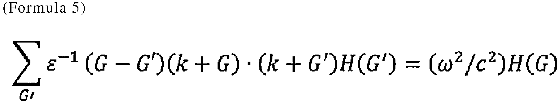
- Herein, ε-1 denotes an inverse number of a dielectric constant, G denotes a reciprocal lattice vector, ω denotes frequency, c denotes light velocity, and k denotes a wave number vector.
- It should be noted that the photonic band structure of the TE polarized components is analyzed herein in order to cause light with the wavelength λ from the light emitting layer to be maximally reflected by the interface to the light extraction surface side. This can be explained by the fact that the electric field of TE light will easily accumulate on the plane of the periodic structure at a connected portion of dielectrics that are provided in parallel with the plane of the periodic structure, and thus that light with the wavelength λ will be reflected by the plane of the electric field due to Bragg scattering when the parameters of the periodic structure and the wavelength λ satisfy the Bragg scattering conditions.
- Further, the parameters of the photonic crystal
periodic structure - According to the third aspect, TE light from the light emitting layer is reflected by the photonic crystal periodic structure. Thus, it is possible to increase the degree of freedom of selection of the types of the reflecting electrode layer and the metal layer and improve the LEE.
- A deep ultraviolet LED in accordance with the fourth aspect of the present invention, is a deep ultraviolet LED characterized in that the formation (processing) depth h of the photonic crystal
periodic structure GaN contact layer 3 and the transparent p-AlGaN contact layer 4 is desirably greater than or equal to 2/3 of the period a, and more preferably, and in accordance with the invention greater than or equal to the period a. - Even the depth h that is greater than or equal to 2/3 of the period a is effective as a reflecting photonic crystal periodic structure in view of the limitation of the processing accuracy due to the high aspect ratio. However, it is desirable to provide the depth h that is greater than or equal to the period a as in the fourth aspect by overcoming the limitation of the accuracy using the production method described below.
- According to the fourth aspect, the effect of improving the LEE can be maximally extracted.
- The deep ultraviolet LED in accordance with a second embodiment, according to the present invention, is a deep ultraviolet LED characterized in that the photonic crystal periodic structure described in the fourth aspect is the photonic crystal periodic structure 110 (
reference numeral 110 of Fig. IE) that penetrates all layers of from the Al reflectingelectrode layer 1 to the transparent p-AlGaN contact layer 4. - According to the said second embodiment, the photonic crystal
periodic structure 110 can be formed at a time (in succession) such that it penetrates layers of from the reflecting electrode layer. Thus, the technical difficulty of forming the photonic crystal periodic structure in some of the layers in the LED can be avoided, thus enabling simplification of the production steps and cost reduction. - A deep ultraviolet LED in accordance with the third embodiment, according to the present invention, is a deep ultraviolet LED that has the deep ultraviolet LED structure described in the second embodiment and has a structure in which layers described below are sequentially and relatively stacked. That is, as exemplarily described above, the deep ultraviolet LED includes, from the substrate side, the p-
AlGaN layer 5 as a p-type nitride semiconductor layer, the transparent p-AlGaN contact layer 4 as a transparent p-type nitride semiconductor contact layer, and the p-GaN contact layer 3 as a contact layer on the metal layer side. The reflecting electrode layer and the metal layer can be obtained by, though not particularly limited thereto, combining an Al (or Au) reflecting electrode and a Ni (or Pd or Pt) layer. In particular, as the type of metal, metal whose adhesion to the inner wall of the circular hole can be suppressed is desirably used. - According to the third embodiment, a highly advantageous effect of improving the LEE of the deep ultraviolet LED can be expected to be achieved by adopting such a layer structure.
- A deep ultraviolet LED in accordance with the fourth embodiment is a deep ultraviolet LED characterized in that the photonic crystal
periodic structure - It should be noted that photoresist used in the imprint technology of the nanoimprinting lithography method should have high fluidity so as to closely fill a mold with a fine projection/recess structure pattern. However, the fluidity will cause deterioration of the etching selectivity of the transparent p-
AlGaN contact layer 4. Herein, the deep ultraviolet LED in accordance with the fifth embodiment, outside the scope of the present invention, is a deep ultraviolet LED characterized by having a photonic crystal periodic structure formed by a imprint technology using a bi-layer resist method that can provide both high fluidity and high etching selectivity. - According to the fourth embodiment, a photonic crystal periodic structure designed in accordance with this embodiment can be accurately imprinted to resist in a large area in units of nm. According to the fifth embodiment, it is possible to form a photonic crystal periodic structure with a high aspect ratio designed in accordance with any of the embodiments.
- An example of the present invention will be described with reference to
Fig. 1A . The following table (Table 1) shows the composition, dope, film thickness, refractive index, and the like of each layer. The design wavelength λ is 280 nm. The reflecting photonic crystal periodic structure formed has a photonic band gap with respect to the wavelength λ, and reflects light from the light emitting layer toward the light extraction layer side, that is, to thesapphire substrate 12 side.[Table 1] 280 nm Al Content [%] Dope Thickness [nm] Refractive Index Extinction Coefficient Al Electrode Layer Reflect 90% 150 0.246 3.401 Ni Layer Absorb 10 1.681 2.067 p-GaN Contact Layer Absorb 50 2.76 0.75 Transparent p-AIGaN Contact Layer Transmit 95 % or More 50 Mg 250 2.65 p- AlGaN Layer 60 Mg 20 2.56 Electron Blocking Layer 95 Mg 20 2.28 Barrier Layer 60 10 2.56 Well Layer 40 10 2.77 Barrier Layer 60 10 2.56 n- AlGaN Buffer Layer 60 Si 200 2.56 AlN Buffer Layer 500 2.24 Sapphire Substrate 1500 1.82 - The photonic crystal periodic structure is a reflecting photonic crystal periodic structure that includes circular holes with bottom surfaces at the interface between the transparent p-
AlGaN contact layer 4 and the p-AlGaN layer 5, and has a triangular lattice formed by the circular holes as a unit structure. Two structures with different refractive indices that form such a periodic structure are transparent p-AlGaN and the air or another medium. The average refractive index nav thereof is determined by the following formula (Formula 3). - It should be noted that the transparent p-
AlGaN contact layer 4 and the p-AlGaN layer 5 may be combined as a single layer. The transparent p-AlGaN contact layer 4 may simply be referred to as a p-type AlGaN layer. The composition, dope, film thickness, refractive index, and the like of each layer, including Table 1, are exemplary values used in the simulation. Thus, the structure of the deep ultraviolet LED, including transparency, is not limited to the parameters shown in the table. - In Example 1 herein, it is desirable that the photonic crystal
periodic structure 110 be ideally formed such that it penetrates all layers of from the Al reflectingelectrode layer 1 to the transparent p-AlGaN contact layer 4, and also that the air be used as the medium of the circular hole in view of the production cost and the like. Meanwhile, when the photonic crystalperiodic structure 100 that penetrates only the p-GaN contact layer 3 and the transparent p-AlGaN contact layer 4 is formed, using a liftoff method in the stacking step will allow the use of the air as the medium of the circular hole as with the photonic crystalperiodic structure 110 that is formed such that it penetrates all layers of from the Al reflectingelectrode layer 1 to the transparent p-AlGaN contact layer 4. In addition, the medium is not necessarily limited to the air as long as, if the high-level technical problem and cost disadvantages can be overcome, it has a lower refractive index than the transparent p-AlGaN contact layer 4 and does not absorb light with the wavelength λ. - It should be noted that the transparent p-
AlGaN contact layer 4 may combine the function of the p-AlGaN layer 5. In such a case, the bottom surfaces of the circular holes (i.e., depth h) may be located in the p-AlGaN layer 5.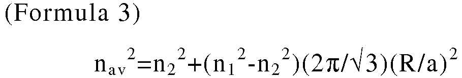
- Herein, R/a that is the ratio of the radius R of the circular hole to the period a is finally determined as a value at which the LEE is the maximum through the following steps. However, R/a is tentatively determined herein. The average refractive index nav is computed assuming that the tentatively determined R/a is 0.40, the refractive index (n2) of the transparent p-
AlGaN contact layer 4 is 2.65, and the refractive index (n1) of the air is 1.00. - Next, the radius R and the period a corresponding to the tentatively determined R/a (0.40) are determined from the nav (1.88) herein and the Bragg scattering conditions of the following formula (Formula 4) for each order m (1 < m < 5).
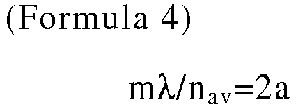
- As a result, it is found that a=149 and R=59.5 when m=2; a=224 and R=89.5 when m=3; and a=298 and R=119.5 when m=4.
- Further, the band structure is analyzed by a plane wave expansion method using the tentatively determined R/a, the refractive indices n1 and n2, and the dielectric constants ε1 (1.00) and ε2 (7.02) corresponding thereto. Specifically, the dielectric constants ε1 and ε2 and R/a are input to the Maxwell's electromagnetic field wave equation represented by the following formula (Formula 5), which has been obtained by expanding a plane wave with a wavelength of λ by a magnetic field H, to compute eigen values in the wave number space and thus determine the photonic band structure of the TE polarized components. Then, the photonic band gap is determined from the thus determined band structure.
- Again, new R/a (in Example 1 herein, R/a=0.25, 0.30, 0.35, etc.) is tentatively determined to determine the photonic band gap of the TE polarized components in the same way. Such a step is repeated to study which R/a provides the maximum photonic band gap, and thus select a candidate R/a. The period a and the radius R are computed from the selected candidate R/a for each order m of the Bragg scattering conditions as described above, and further, the processing depth h of the photonic crystal periodic structure is added as a parameter to conduct simulation using the FDTD method. Then, a combination of the order m, the period a, the radius R, and the depth h at which the maximum LEE is exhibited is determined. Consequently, it was determined that R/a=0.40, the order m=4, the period a=298 nm, and the radius R=119.5 nm in Example 1 herein.
- The LEE rate of change that is an index of the advantageous effect of Example 1 herein is represented by the following formula (Formula 6), that is, the rate of change of the
output 2 relative to theoutput 1.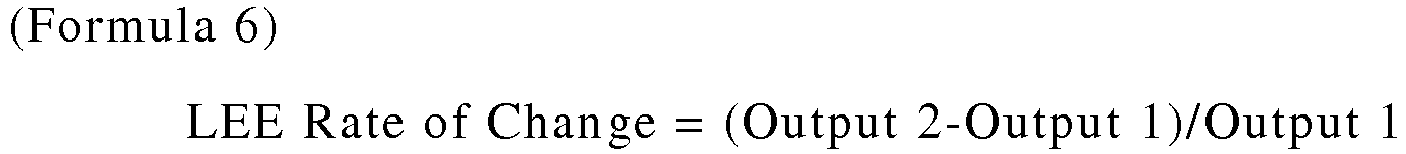
- Herein, the
output 2 is the optical output value of the LED structure that is the result of Example 1 herein, while theoutput 1 is the optical output value as a reference to be compared with theoutput 2. The LED structure corresponding to theoutput 1 is as shown in the following table (Table 2) andFig. 2 . The LED structure herein does not have formed therein the reflecting photonic crystal periodic structure in accordance with this embodiment. Further, the structure does not include a metal layer or a p-GaN contact layer, but instead, both the layers are replaced by the transparent p-AlGaN contact layer 4. It should be noted that the optical output value is the value of an optical output from the light emitting layer with the deep ultraviolet LED structure that is received by a monitor arranged on each of the side surfaces (i.e., four outer wall surfaces) and the front surfaces (i.e., top surface and bottom surface) of the LED used for a simulation model based on the FDTD method.[Table 2] 280 nm Al Content [%] Dope Thickness [nm] Refractive Index Extinction Coefficient Al Electrode Layer Reflect 90% 160 0.246 3.401 Ni Layer Absorb 0 1.681 2.067 p-GaN Contact Layer Absorb 0 2.76 0.75 Transparent p-AlGaN Contact Layer Transmit 95 % or More 50 Mg 300 2.65 p- AlGaN Layer 60 Mg 20 2.56 Electron Blocking Layer 95 Mg 20 2.28 Barrier Layer 60 10 2.56 Well Layer 40 10 2.77 Barrier Layer 60 10 2.56 n- AlGaN Buffer Laver 60 Si 200 2.56 AlN Buffer Layer 500 2.24 Sapphire Substrate 1500 1.82 - Table 3 and
Fig. 3 show the simulation results of the FDTD based on the parameters of the reflecting photonic crystal periodic structure determined by the aforementioned design. Specifically, inFig. 3 , a combination of the thicknesses of the p-GaN contact layer 3 and the transparent p-AlGaN contact layer 4 and the depth h at which the photonic crystal periodic structure is formed were used as parameters, and the LEE of the front surface output of each LED structure was compared with the LEE of the front surface output of the LED structure inFig. 2 so as to be compared as the LEE rate of change.[Table 3] LEE Rate of Change [%] (Front Surface Output) Depth at which PhC is formed ([nm]) → p-GaN Contact Layer/ Transparent p-AIGaN Contact Layer ([nm]/[nm]) 0 (Without PhC) 100 200 300 460 (Penetrate) 0/300 0 50/250 -51 -5 38 123 112 100/200 -51 -16 35 113 108 200/100 -51 -50 27 118 118 300/0 -44 -44 -41 75 77 - Table 3 and the ordinate axis of
Fig. 3 show the LEE rate of change ([%]) of the output of the front surface of the LED. The leftmost column of Table 3 and the abscissa axis ofFig. 3 represent a combination of the thicknesses of the p-GaN contact layer 3 and the transparent p-AlGaN contact layer 4 (represented by [nm]/[nm]), which include 0/300, 50/250, 100/200, 200/100, and 300/0. It should be noted that the total thickness of the two layers herein was set to 300 nm for the sake of convenience to compare the increase/decrease of the LEE in accordance with not only the influence of the thickness of each layer but also the ratio of the thicknesses of the two layers. Herein, the case of 300/0 corresponds to a comparison example of Example 1 herein, which represents a LED structure without the transparent p-AlGaN contact layer in accordance with the embodiment of the present invention. Likewise, the case of 0/300 represents the LED structure inFig. 2 (without a photonic crystal periodic structure) corresponding to theoutput 1 that is the reference used to compute the LEE rate of change. - The uppermost row of Table 3 and the axis in the depth direction of
Fig. 3 represent the depth h at which the photonic crystal periodic structure is formed, which include 0, 100, 200, 300, and 460 nm. The case where the depth h is 300 nm corresponds to a case where a periodic structure is formed in each of the p-GaN contact layer 3 and the transparent p-AlGaN contact layer 4. Likewise, the case where the depth is 460 nm corresponds to a case where a periodic structure is formed such that it penetrates all layers of from the Al reflectingelectrode layer 1 to the transparent p-AlGaN contact layer 4. In Table 3 andFig. 3 , this is indicated by "Penetrate." The case where the depth is 0 nm represents the output 1 (LEE rate of change = 0), which is the reference used to compute the LEE increase-decrease rate, of the LEE structure inFig. 2 . - As is clear from the results shown in Table 3 and
Fig. 3 , the front surface output of the LED is significantly increased by the introduction of the transparent p-AlGaN contact layer 4 and the formation of the reflecting photonic crystalperiodic structure GaN contact layer 3 that absorbs light with the wavelength λ was suppressed to the range of 50 to 200 nm, while the transparent p-AlGaN contact layer 4 in the range of 250 to 100 nm was introduced, and further, the reflecting photonic crystal periodic structure was formed at a depth h of greater than or equal to 300 nm that is about equal to the period a, whereby it was possible to obtain a LEE rate of change of greater than or equal to 113% for the front surface output of the LED, that is, an output that is 2.13 times that of theoutput 1. Such advantageous effect is recognized regardless of whether or not the reflecting photonic crystal periodic structure is formed such that it penetrates layers of from the Al reflectingelectrode layer 1 to the transparent p-AlGaN contact layer 4. When the depth h of the photonic crystal periodic structure is 200 nm, the LEE rate of change (i.e., front surface output) is increased. This corresponds to the depth of about 2/3 of the period a of the structure in this example. From the results, it can be said that the reflection effect of the photonic crystal periodic structure appears even when the depth is greater than or equal to 2/3 of the period a. - Likewise, Table 4 and
Fig. 4 show the LEE increase-decrease rate of the total output of the side surfaces and the front surfaces of the LED, while Table 5 andFig. 5 show the LEE rate of change of the side surface output.[Table 4] LEE Rate of Change [%] (Total Output) Depth at which PhC is formed ([nm]) → p-GaN Contact Layer/ Transparent p-AIGaN Contact Layer ([nm]/[nm]) 0 (Without PhC) 100 200 300 460 (Penetrate) 0/300 0 50/250 -61 -23 -15 17 19 100/200 -64 -40 -19 14 16 200/100 -65 -65 -36 11 12 300/0 -65 -65 -65 -17 -16 [Table 5] LEE Rate of Change [%] (Side Surface Output) Depth at which PhC is formed ([nm]) → p-GaN Contact Layer/ Transparent p-AIGaN Contact Layer ([nm]/[nm]) 0 (Without PhC) 100 200 300 460 (Penetrate) 0/300 0 50/250 -63 -25 -23 2 0 100/200 -66 -43 -26 1 -1 200/100 -66 -66 -44 -3 -4 300/0 -67 -67 -67 -30 -30 - From Table 4 and
Fig. 4 , similar results to those of the aforementioned discussion can be obtained. Specifically, introducing the transparent p-AlGaN contact layer 4 in the range of 250 to 100 nm (suppressing the range of the p-GaN contact layer to 50 to 200 nm) and forming the reflecting photonic crystal periodic structure at a depth h of greater than or equal to 300 nm can obtain LEE that is 1.19 times higher at a maximum. - It should be noted that depending on the package structure of the LED or the application of the LED, a reference used to determine whether or not each of the parameters of the photonic crystal periodic structure at that time is optimum will differ in accordance with the results of the FDTD simulation. That is, a variety of references, such as the output of the front surfaces of the LED, the total output of the output of the front surfaces and the output of the side surfaces of the LED, or luminance characteristics in the near field or the far field, may be used. Conversely, depending on the reference used, each of the parameters of the reflecting photonic crystal periodic structure that are evaluated as optimal and thus are determined will differ. It should be noted that the near field is mainly referred to when the LEE rate of change is observed, while the far field is referred to when the LEE rate of change and the angular distribution of the radiation pattern are observed.
- In Example 2 herein, the LEE rate of change of the front surface output of a LED with a photonic crystal periodic structure, which is formed such that it penetrates all layers (460 nm) of from the reflecting
electrode layer 1 to the transparent p-AlGaN contact layer 4, was compared for cases where the type of the electrode differs: Al or Au. Table 6 shows the LED structure when the thicknesses of the p-GaN contact layer 3 and the transparent p-AlGaN contact layer 4 are 200 and 100, respectively, and an Au electrode is used. Table 7 shows the results of comparison between the influence of the difference of the electrode on the LEE of the front surface output of the LED for each combination of the thicknesses of the p-GaN contact layer 3 and the transparent p-AlGaN contact layer 4 with the LEE of the LED structure inFig. 2 .Fig. 6 shows a diagram thereof.[Table 6] 280 nm Al Content[%] Dope Thickness [nm] Refractive Index Extinction Coefficient Au Electrode Layer Reflect 60% 130 1.659 1.861 Ni Layer Absorb 30 1.681 2.067 p-GaN Contact Laver Absorb 200 2.76 0.75 Transparent p-AlGaN Contact Layer Transmit 95 % or More 50 Mg 100 2.65 p- AlGaN Layer 60 Mg 20 2.56 Electron Blocking Laver 95 Mg 20 2.28 Barrier Layer 60 10 2.56 Well Laver 40 10 2.77 Barrier Layer 60 10 2.56 n- AlGaN Buffer Layer 60 Si 200 2.56 AlN Buffer Laver 500 2.24 Sapphire Substrate 1500 1.82 [Table 7] LEE Rate of Change [%] (Front Surface Output) Depth at which PhC is formed ([nm]) → p-GaN Contact Layer/ Transparent p-AIGaN Contact Layer ([nm]/[nm]) 0 (Without PhC) 460 Al Electrode (Penetrate) 460 Au Electrode (Penetrate) 0/300 0 50/250 112 112 100/200 108 108 200/100 118 117 300/0 77 76 - As is clear from the tables and drawing, there is no big difference in the LEE rate of change depending on whether an Al electrode or an Au electrode is used when the other conditions are the same. Thus, introducing the LED structure and the reflecting photonic crystal periodic structure in accordance with the present invention can increase the degree of freedom of selection of the reflecting electrode material as needed.
- In Examples 1 and 2 above, the combination of the thicknesses of the p-
GaN contact layer 3 and the transparent p-AlGaN contact layer 4 that form the photonic crystalperiodic structure GaN contact layer 3 and the transparent p-AlGaN contact layer 4 and the effect of suppressing absorption of light by the p-GaN contact layer 3 due to the introduction of the photonic crystal periodic structure (i.e., the reflection effect of the photonic crystal periodic structure). In the deep ultraviolet LED structure shown in the following table (Table 8), the thickness of the p-GaN contact layer 3 was changed in increments of 10 nm in the range of 200 to 300 nm, and the LEE increase-decrease rates due to the difference were compared and studied (Table 9). Herein, the photonic crystalperiodic structure 110 that penetrates all layers of from the Al reflectingelectrode layer 1 to the transparent p-AlGaN contact layer 4 was formed by setting the parameters of the photonic crystal periodic structure such that the order m of the Bragg scattering conditions is 4, the radius R of the circular hole is 119.5 nm, the period a is 298 nm, and the depth h is 460 nm. It should be noted that (Table 9) also shows as a reference the result of the LEE increase-decrease rate when, for the p-GaN contact layer 3 in the thickness range of 0 to 200, the combination of the thicknesses of the p-GaN contact layer 3 and the transparent p-AlGaN contact layer 4 confirmed in Example 1 is set to 50 nm.[Table 8] 280 nm Al Content [%] Dope Thickness [nm] Refractive Index Extinction Coefficient Al Electrode Layer Reflect 90% 150 0.246 3.401 Ni Layer Absorb 10 1.681 2.067 p-GaN Contact Layer Absorb 260 2.76 0.75 Transparent p-AlGaN Contact Layer Transmit 95 % or More 50 Mg 40 2.65 p-AlGaN Layer 60 Mg 20 2.56 Electron Blocking Layer 95 Mg 20 2.28 Barrier Layer 60 10 2.56 Well Layer 40 10 2.77 Barrier Layer 60 10 2.56 n-AlGaN Buffer Layer 60 Si 200 2.56 AlN Buffer Layer 500 2.24 Sapphire Substrate 1500 1.82 [Table 9] LEE Rate of Change [%] (PhC, Order m: 4) P-GaN Contact Layer/ Transparent p-AIGaN Contact Layer 460 nm (Penetrate) (Front Surface Output) 460 nm (Penetrate) (Side Surface Output) 460 nm (Penetrate) (Total Output) 0/300 nm 50/250 112% 0 19% 100/200 108 -1 16 200/100 118 -4 12 210/90 111 -4 11 220/80 104 -4 10 230/70 98 -5 8 240/60 95 -6 7 250/50 90 -8 5 260/40 83 -10 2 270/30 75 -13 -3 280/20 70 -18 -7 290/10 71 -23 -11 300 nm/0 nm 77 -30 -16 - As shown in Table 9, when the thickness of the p-GaN contact layer is 260 nm (in this case, the thickness of the transparent p-AlGaN contact layer is 40 nm), the LEE rate of change (i.e., total output) is increased by 2 %. From the results, it is considered that when the order m of the Bragg scattering conditions as the parameter of the photonic crystal periodic structure is set to 4, it is possible to, by setting the thickness of the p-
GaN contact layer 3 to less than or equal to 260 nm (in this case, the thickness of the transparent p-AlGaN contact layer 4 is 40 nm), completely suppress absorption of light by the p-GaN contact layer 3, so that the reflection effect due to the introduction of the reflecting photonic crystal periodic structure appears. As described above, the transparent p-AlGaN contact layer 4 is present, and has a certain thickness.[Table 10] LEE Rate of Change [%] (Phc, Order m: 3) P-GaN Contact Layer/ Transparent p-AlGaN Contact Layer 390 nm (Penetrate) (Front Surface Output) 390 nm (Penetrate) (Side Surface Output) 390 nm (Penetrate) (Total Output) 0 nm/300 nm 94% 4% 20% 50/250 32 -9 -3 100/200 20 -9 -6 150/150 8 -9 -9 200/100 -3 -18 -18 - Further, the relationship between the effect of suppressing absorption of light by the p-
GaN contact layer 3 due to the introduction of the reflecting photonic crystal periodic structure and the thicknesses of the p-GaN contact layer 3 and the transparent p-AlGaN contact layer 4 was also compared and studied for a case where the order m of the Bragg scattering conditions as a parameter of the photonic crystal periodic structure was set to 3 (Table 10). In this case, the radius R of the circular hole was set to 89.5 nm, the period a was set to 224 nm, and the depth h was set to 390 nm so as to allow the thickness of only a portion, which penetrates the p-GaN contact layer 3 and the transparent p-AlGaN contact layer 4, of the photonic crystalperiodic structure 110 that is formed such that it penetrates all layers of from the Al reflectingelectrode layer 1 to the transparent p-AlGaN contact layer 4 to be greater than or equal to the period a as in the case where the order m of the Bragg scattering conditions is set to 4. The thickness of the p-GaN contact layer 3 was changed in increments of 50 nm in the range of 0 to 200 nm. - As is clear from Table 10, even when the order m is 3, it is considered that the advantageous effect of suppressing absorption of light by the p-
GaN contact layer 3 due to the introduction of the reflecting photonic crystal periodic structure is expected to be achieved as long as the p-GaN contact layer 3 has a thickness that is less than about 50 nm. - The steps of specifically forming the photonic crystal periodic structures described in Examples 1 to 3 above using a nanoimprinting lithography method will be hereinafter described with reference to the drawings. Although an example of the photonic crystal
periodic structure 110 shown in Fig. IE, which is formed such that it penetrates all layers of from the Al reflectingelectrode layer 1 to the transparent p-AlGaN contact layer 4, will be described, the basic steps are the same even when the photonic crystalperiodic structure 100 that penetrates both the p-GaN contact layer 3 and the transparent p-AlGaN contact layer 4 is formed. - First, a mold for accurately reproducing the photonic crystal
periodic structure resin mold 200 is desirably used so that it can follow the warp of the substrate and the layers stacked thereon, which would become prominent if the substrate size is increased. - It should be noted that photoresist used in the imprint technology of the nanoimprinting lithography method should have high fluidity so as to closely fill a mold with a fine projection/recess structure pattern. However, the fluidity will cause deterioration of the etching selectivity of the transparent p-
AlGaN contact layer 4. Thus, a bi-layer resist method, which can provide both high fluidity and high etching selectivity, is suitable for solving such a problem. - Specifically, an organic resist material such as novolac resin, which will improve the etching selectivity of the transparent p-
AlGaN contact layer 4, is applied onto the Al reflectingelectrode layer 1 by a spin coater or the like for the stacked structure of the deep ultraviolet LED in which layers of up to the Al reflectingelectrode layer 1 have been stacked (Figs. 1A and1B ), whereby an organic resistfilm 231 is formed. Further, silicon-containing resist with high fluidity is applied onto the organic resistfilm 231 to form a silicon-containing resist film 232 (Fig. 7 ). The thickness of the silicon-containing resistfilm 232 is controlled so as to favorably secure the mold release characteristics of the mold, taking into consideration the viscosity of the material and the like. Typically, the silicon-containing resistfilm 232 may be thinner than the organic resistfilm 231. - The photonic crystal
periodic structure film 232 using theresin mold 200 with the use of the nanoimprinting lithography method, the basic structure of which is shown inFig. 8 . It should be noted that a silicon-containing resistfilm 232d remains in the recessed portions of the fine projection/recess structure during imprint (Fig. 9 ). - Next, the silicon-containing resist
film 232d that remains in the recessed portions is etched byplasma 301 of oxygen-containing gas and fluorine-containing gas until the organic resistfilm 231 is exposed. At this time, the projection portions of the silicon-containing resistfilm 232 are also etched (Fig. 10 ). - After that, the silicon-containing resist
film 232 is exposed to oxygen-containing plasma to form asilicon oxide film 232a, and then, a region of from the Al reflectingelectrode layer 1 up to the interface between the transparent p-AlGaN contact layer 4 and the p-AlGaN layer 5 is etched at a time by chlorine-containingplasma 302 with thesilicon oxide film 232a used as a mask (Fig. 11 ). As the chlorine gas, Cl2, BCl, or the like is used. Using the chlorine-containingplasma 302 can secure high selectivity of the transparent p-AlGaN contact layer 4 with respect to the mask. Thus, high-accuracy processing with a high aspect ratio is possible. Finally, the organic resistfilm 231 and thesilicon oxide film 232a are removed by ashing (Fig. 12 ). - Although this embodiment has illustrated an example of an AlGaN-based deep ultraviolet LED (Light Emitting Diode), it can also be applied to optical semiconductor light emitting elements made of other materials as long as such light emitting elements have similar structures.
-
- 1) When the film thickness of the p-GaN contact layer is about 200 nm, it is possible to totally reflect incident light and suppress absorption, and thus improve the total value of the LEE increase-decrease rate by 10 % or more as long as the depth of the photonic crystal is greater than or equal to 1 period.
- 2) In the case of 1), the Ni layer can be formed as thick as about 10 to 30 nm. Thus, it is possible to obtain ohmic contact with the p-GaN contact layer, suppress an increase in the drive voltage, and drastically improve the WPE.
- 3) In the case of 1), the degree of freedom of selection of the reflecting electrode material is increased.
- 4) A nanoimprinting method that uses bi-layer resist can create a photonic crystal at a time such that it penetrates layers of from a reflecting electrode to a p-GaN contact layer. Thus, as it is not necessary to perform high-precision positioning such as a liftoff process for fine patterns, there is a significant advantage in the production cost.
- A process, such as simulation, and control can be implemented by software processing with a CPU (Central Processing Unit) or a GPU (Graphics Processing Unit) or by hardware processing with an ASIC (Application Specific Integrated Circuit) or a FPGA (Field Programmable Gate Array).
- In the aforementioned embodiments, structures and the like that are shown in the attached drawings are not limited thereto, and can be changed appropriately within the range in which the advantageous effects of the present invention can be achieved. Besides, such structures and the like can be implemented by being changed appropriately within the scope of the objects of the present invention.
- Each component of the present invention can be freely selected, and an invention with a freely selected structure is also included in the present invention.
- It is also possible to record a program for implementing the function described in this embodiment on a computer-readable recording medium, and cause a computer system to read the program recorded on the recording medium and execute the program so as to perform a process of each unit. It should be noted that the "computer system" herein includes an OS and hardware of peripheral devices and the like.
- In addition, the "computer system" also includes a website providing environment (or displaying environment) if the system uses a www system.
- The "computer-readable recording medium" means a portable medium such as a flexible disk, a magneto-optical disk, ROM, or CD-ROM; or a storage device such as a hard disk incorporated in a computer system. Further, the "computer-readable recording medium" also includes a medium that dynamically holds a program for a short period of time, such as a communication line for transmitting a program via a network like the Internet or a communication line like a telephone line, and a medium that holds a program for a given period of time, like a volatile memory in a computer system that serves as a server or a client in the that case. Alternatively, the program may implement some of the aforementioned functions, and may further implement the aforementioned functions by being combined with a program that is already recorded in the computer system. At least some of the functions may be implemented by hardware such as an integrated circuit.
- The present invention is applicable to deep ultraviolet LEDs.
-
- 1
- Al (or Au) reflecting electrode layer
- 2
- Ni (or Pd) layer
- 3
- p-GaN contact layer
- 4
- Transparent p-AlGaN contact layer
- 5
- p-AlGaN layer
- 6
- Electron blocking layer
- 7
- Barrier layer
- 8
- Quantum well layer
- 9
- Barrier layer
- 10
- n-AlGaN layer
- 11
- AlN buffer layer
- 12
- Sapphire substrate
- 100
- Photonic crystal periodic structure
- 110
- Photonic crystal periodic structure
- 200
- Resin mold
- 210
- UV light source
- 220
- High tracking mechanism
- 230
- Photoresist
- 231
- Organic resist film
- 232
- Silicon-containing resist film
- 240
- High-rigidity/high-precision stage
- 301
- Plasma of oxygen-containing gas and fluorine-containing gas
- 302
- Chlorine-containing plasma
Claims (8)
- A deep ultraviolet LED with a design wavelength of λ, comprising:a reflecting electrode layer (1), a metal layer (2), a p-type GaN contact layer (3), and a p-type AlGaN layer (4) that are sequentially stacked from a side opposite to a substrate (12), the p-type AlGaN layer (4) being transparent to light with the wavelength of λ; anda reflective-type photonic crystal periodic structure (100/110) with a plurality of circular holes (101/111) with a radius of R provided in a range including at least an interface between the p-type GaN contact layer (3) and the p-type AlGaN layer (4) and within the p -type AlGaN layer (4) in a thickness direction to the substrate (12), characterized in thatthe reflective-type photonic crystal periodic structure (100/110) has a photonic band gap open to TE polarized components, the photonic crystal periodic structure includes two structures including air and the AlGaN layer at a bottom surface portion of the photonic crystal periodic structure on the substrate side, the wavelength λ, a period a, an average refractive index nav of the two structures satisfy Bragg scattering conditions, an order m of the Bragg scattering conditions is in a range of 1 < m < 5, wherein R/a has a value with the maximum photonic band gap and the depth h of the holes that is greater than or equal to the period a.
- The deep ultraviolet LED according to claim 1, wherein the reflective-type photonic crystal periodic structure (100/110) is provided in the reflecting electrode layer (1) and the metal layer (2).
- The deep ultraviolet LED according to claim 1 or 2, wherein the depth h of the photonic crystal periodic structure (100/110) is greater than or equal to a thickness of the p-type AlGaN layer (4), and is less than or equal to a total thickness of the p-type GaN contact layer (3) and the p-type AlGaN layer (4).
- The deep ultraviolet LED according to any one of claims 1 to 3, further comprising, in addition to the p-type AlGaN layer (4), another p-type AlGaN layer (5) on the substrate side, the other p-type AlGaN layer (5) having a higher Al content than the p-type AlGaN layer (4).
- The deep ultraviolet LED according to any one of claims 1 to 4, wherein the photonic crystal periodic structure (100/110) is formed using a imprint technology of a nanoimprinting lithography method.
- The deep ultraviolet LED according to claim 5, wherein the reflective-type photonic crystal periodic structure is formed by dry etching using a bi-layer resist method that uses resist with high fluidity and resist with high etching selectivity.
- A method for manufacturing a deep ultraviolet LED, comprising:a step of preparing a stacked structure with a design wavelength of λ, the stacked structure including a reflecting electrode layer (1), a metal layer (2), a p-type GaN contact layer (3), and a p-type AlGaN layer (4) that are sequentially stacked from a side opposite to a substrate (12), the p-type AlGaN layer (4) being transparent to light with the wavelength of λ;a step of preparing a mold for forming a reflective-type photonic crystal periodic structure (100/110) with a plurality of circular holes (101/111) with a radius of R, the reflective-type photonic crystal periodic structure (100/110) being provided in a range including at least an interface between the p-type GaN contact layer (3) and the p-type AlGaN layer (4) and within the p-type AlGaN layer (4) in a thickness direction to the substrate (12); characterized in that the reflective-type photonic crystal periodic structure (100/110) has a photonic band gap open to TE polarized components, the photonic crystal periodic structure includes two structures including air and the AlGaN layer at a bottom surface portion of the photonic crystal periodic structure on the substrate side, the wavelength λ, a period a, an average refractive index nav of the two structures satisfy Bragg scattering conditions, an order m of the Bragg scattering conditions is in a range of 1 < m < 5, wherein R/a has a value with the maximum photonic band gap and the depth h of the holes that is greater than or equal to the period a;a step of forming a resist layer on the stacked structure and imprinting a structure of the mold to the resist layer; anda step of forming a photonic crystal periodic structure (100/110) by sequentially etching the stacked structure using the resist layer as a mask.
- The method for manufacturing a deep ultraviolet LED according to claim 7,wherein the step of forming a resist layer on the stacked structure and imprinting a structure of the mold to the resist layer includesa step of forming dry etching on the stacked structure using a bi-layer resist method of a first resist layer with high fluidity and a second resist layer with high etching selectivity with respect to the first resist layer, anda step of imprinting the structure of the mold to the first resist layer using a nanoimprinting lithography method, andwherein the step of forming the reflective-type photonic crystal periodic structure (100/110) by sequentially etching the stacked structure using the resist layer as a mask includesetching the first resist layer and the second resist layer until the second resist layer is exposed, and also etching a pattern projection portion of the first resist layer, anda step of forming the reflective-type photonic crystal periodic structure (100/110) by sequentially etching the stacked structure using the second resist layer as a mask.
Applications Claiming Priority (2)
| Application Number | Priority Date | Filing Date | Title |
|---|---|---|---|
| JP2014043388 | 2014-03-06 | ||
| PCT/JP2014/078308 WO2015133000A1 (en) | 2014-03-06 | 2014-10-24 | Deep ultraviolet led and method for manufacturing same |
Publications (3)
| Publication Number | Publication Date |
|---|---|
| EP2942818A1 EP2942818A1 (en) | 2015-11-11 |
| EP2942818A4 EP2942818A4 (en) | 2015-11-25 |
| EP2942818B1 true EP2942818B1 (en) | 2018-01-31 |
Family
ID=53189543
Family Applications (1)
| Application Number | Title | Priority Date | Filing Date |
|---|---|---|---|
| EP14841324.8A Active EP2942818B1 (en) | 2014-03-06 | 2014-10-24 | Deep ultraviolet led and method for manufacturing the same |
Country Status (7)
| Country | Link |
|---|---|
| US (1) | US9806229B2 (en) |
| EP (1) | EP2942818B1 (en) |
| JP (1) | JP5757512B1 (en) |
| KR (1) | KR101648079B1 (en) |
| CN (1) | CN105934833B (en) |
| TW (1) | TWI523268B (en) |
| WO (1) | WO2015133000A1 (en) |
Cited By (1)
| Publication number | Priority date | Publication date | Assignee | Title |
|---|---|---|---|---|
| US10923625B2 (en) * | 2018-06-05 | 2021-02-16 | Samsung Electronics Co., Ltd. | Multi-wavelength light source device, multi-function projector including the same, and electronic device including the multi-function projector |
Families Citing this family (13)
| Publication number | Priority date | Publication date | Assignee | Title |
|---|---|---|---|---|
| US9349918B2 (en) | 2011-07-12 | 2016-05-24 | Marubun Corporation | Light emitting element and method for manufacturing same |
| US9929311B2 (en) | 2013-07-17 | 2018-03-27 | Marubun Corporation | Semiconductor light emitting element and method for producing the same |
| EP2942818B1 (en) | 2014-03-06 | 2018-01-31 | Marubun Corporation | Deep ultraviolet led and method for manufacturing the same |
| WO2016113935A1 (en) * | 2015-01-16 | 2016-07-21 | 丸文株式会社 | Deep ultraviolet led and method for manufacturing same |
| EP3346509B1 (en) * | 2015-09-03 | 2021-06-30 | Marubun Corporation | Deep-ultraviolet led and method for manufacturing same |
| JP6156898B1 (en) * | 2016-03-30 | 2017-07-05 | 丸文株式会社 | Deep ultraviolet LED and manufacturing method thereof |
| WO2017168811A1 (en) | 2016-03-30 | 2017-10-05 | 丸文株式会社 | Deep ultraviolet led and production method therefor |
| US11121229B2 (en) | 2017-12-28 | 2021-09-14 | Vanguard International Semiconductor Corporation | Methods of fabricating semiconductor structures and high electron mobility transistors |
| JP7316610B6 (en) * | 2018-01-26 | 2024-02-19 | 丸文株式会社 | Deep ultraviolet LED and its manufacturing method |
| JP2021150373A (en) * | 2020-03-17 | 2021-09-27 | セイコーエプソン株式会社 | Light emitting device, projector, and display |
| JP7492885B2 (en) * | 2020-09-01 | 2024-05-30 | 旭化成株式会社 | Ultraviolet light emitting device |
| CN112542533B (en) * | 2020-12-01 | 2023-04-14 | 北京大学 | A flip-chip structure deep ultraviolet micro-LED with high electro-optic conversion rate and its preparation method |
| US11957378B1 (en) | 2020-12-18 | 2024-04-16 | Northgate Technologies, Inc. | Anti-microbial surgical access device |
Family Cites Families (75)
| Publication number | Priority date | Publication date | Assignee | Title |
|---|---|---|---|---|
| US5337328A (en) | 1992-05-08 | 1994-08-09 | Sdl, Inc. | Semiconductor laser with broad-area intra-cavity angled grating |
| JPH05315513A (en) | 1992-05-12 | 1993-11-26 | Oki Electric Ind Co Ltd | Lead frame and molding method for resin-sealed body |
| US5955749A (en) * | 1996-12-02 | 1999-09-21 | Massachusetts Institute Of Technology | Light emitting device utilizing a periodic dielectric structure |
| EP1378949A4 (en) | 2001-03-21 | 2006-03-22 | Mitsubishi Cable Ind Ltd | Semiconductor light-emitting device |
| JP3991612B2 (en) | 2001-04-09 | 2007-10-17 | 日亜化学工業株式会社 | Light emitting element |
| US6936854B2 (en) * | 2001-05-10 | 2005-08-30 | Canon Kabushiki Kaisha | Optoelectronic substrate |
| US7194174B2 (en) | 2001-10-19 | 2007-03-20 | Ignis Technologies As | Integrated photonic crystal structure and method of producing same |
| US6878969B2 (en) | 2002-07-29 | 2005-04-12 | Matsushita Electric Works, Ltd. | Light emitting device |
| JP4329374B2 (en) | 2002-07-29 | 2009-09-09 | パナソニック電工株式会社 | LIGHT EMITTING ELEMENT AND MANUFACTURING METHOD THEREOF |
| JP2004200209A (en) | 2002-12-16 | 2004-07-15 | Fuji Xerox Co Ltd | Method of forming conductive patterns such as electrodes, surface emitting semiconductor laser using the same, and method of manufacturing the same |
| JP4610863B2 (en) | 2003-03-19 | 2011-01-12 | フィリップス ルミレッズ ライティング カンパニー リミテッド ライアビリティ カンパニー | Improved LED efficiency using photonic crystal structure |
| JP4317375B2 (en) * | 2003-03-20 | 2009-08-19 | 株式会社日立製作所 | Nanoprint apparatus and fine structure transfer method |
| US7083993B2 (en) | 2003-04-15 | 2006-08-01 | Luminus Devices, Inc. | Methods of making multi-layer light emitting devices |
| US7367691B2 (en) * | 2003-06-16 | 2008-05-06 | Industrial Technology Research Institute | Omnidirectional one-dimensional photonic crystal and light emitting device made from the same |
| US7683377B2 (en) | 2003-07-16 | 2010-03-23 | Panasonic Corporation | Semiconductor light emitting device, method of manufacturing the same, and lighting apparatus and display apparatus using the same |
| US7012279B2 (en) | 2003-10-21 | 2006-03-14 | Lumileds Lighting U.S., Llc | Photonic crystal light emitting device |
| JP2008521211A (en) * | 2004-07-24 | 2008-06-19 | ヨン ラグ ト | LED device including thin-film phosphor having two-dimensional nano-periodic structure |
| US20060043400A1 (en) * | 2004-08-31 | 2006-03-02 | Erchak Alexei A | Polarized light emitting device |
| JP2006196658A (en) | 2005-01-13 | 2006-07-27 | Matsushita Electric Ind Co Ltd | Semiconductor light emitting device and manufacturing method thereof |
| JP2006276388A (en) | 2005-03-29 | 2006-10-12 | Alps Electric Co Ltd | Photonic crystal slab, photonic crystal waveguide and optical device |
| US8101498B2 (en) * | 2005-04-21 | 2012-01-24 | Pinnington Thomas Henry | Bonded intermediate substrate and method of making same |
| US8163575B2 (en) * | 2005-06-17 | 2012-04-24 | Philips Lumileds Lighting Company Llc | Grown photonic crystals in semiconductor light emitting devices |
| TWI253771B (en) | 2005-07-25 | 2006-04-21 | Formosa Epitaxy Inc | Light emitting diode structure |
| JP2007109689A (en) | 2005-10-11 | 2007-04-26 | Seiko Epson Corp | LIGHT EMITTING DEVICE, LIGHT EMITTING DEVICE MANUFACTURING METHOD, AND IMAGE DISPLAY DEVICE |
| US7679098B2 (en) | 2006-01-30 | 2010-03-16 | Avago Technologies Ecbu Ip (Singapore) Pte. Ltd. | Highly directional light emitting diode using photonic bandgap waveguides |
| US7687811B2 (en) | 2006-03-21 | 2010-03-30 | Lg Electronics Inc. | Vertical light emitting device having a photonic crystal structure |
| JP2007294789A (en) | 2006-04-27 | 2007-11-08 | Sony Corp | Semiconductor laser element |
| KR100736623B1 (en) | 2006-05-08 | 2007-07-09 | 엘지전자 주식회사 | Vertical light emitting device and manufacturing method |
| JP4231880B2 (en) | 2006-07-26 | 2009-03-04 | 株式会社東芝 | Three-dimensional structure, light emitting device having the same, and method for manufacturing the same |
| JP2008053425A (en) | 2006-08-24 | 2008-03-06 | Matsushita Electric Ind Co Ltd | Semiconductor light emitting device |
| US7829905B2 (en) | 2006-09-07 | 2010-11-09 | Hong Kong Applied Science And Technology Research Institute Co., Ltd. | Semiconductor light emitting device |
| US7697584B2 (en) * | 2006-10-02 | 2010-04-13 | Philips Lumileds Lighting Company, Llc | Light emitting device including arrayed emitters defined by a photonic crystal |
| JP2008098526A (en) | 2006-10-13 | 2008-04-24 | Toyoda Gosei Co Ltd | Light-emitting element |
| JP2008117922A (en) * | 2006-11-02 | 2008-05-22 | Yamaguchi Univ | Semiconductor light emitting device and manufacturing method thereof |
| KR100886821B1 (en) | 2007-05-29 | 2009-03-04 | 한국광기술원 | Photonic Crystal Light Emitting Device with Improved Electrical Characteristics and Manufacturing Method |
| JP2008311317A (en) | 2007-06-12 | 2008-12-25 | Eudyna Devices Inc | Semiconductor light-emitting element |
| KR101341374B1 (en) | 2007-07-30 | 2013-12-16 | 삼성전자주식회사 | Photonic crystal light emitting device and manufacturing method of the same |
| JP2009267263A (en) | 2008-04-28 | 2009-11-12 | Kyocera Corp | Light-emitting device and method for manufacturing the same |
| KR100933529B1 (en) | 2008-05-28 | 2009-12-23 | 재단법인서울대학교산학협력재단 | Light-Emitting Device with Photonic Crystal Structure |
| EP2286980A4 (en) * | 2008-06-05 | 2011-07-13 | Asahi Glass Co Ltd | NANO-PRINTING MOLD, METHOD FOR MANUFACTURING THE SAME, AND PROCESSES FOR PRODUCING A MOLDED RESIN HAVING A FINE ROUGH STRUCTURE ON A SURFACE AND FOR PRODUCING A METAL GRID POLARIZER |
| JP5282503B2 (en) | 2008-09-19 | 2013-09-04 | 日亜化学工業株式会社 | Semiconductor light emitting device |
| JP5379434B2 (en) | 2008-09-22 | 2013-12-25 | 学校法人 名城大学 | Method for manufacturing sapphire substrate for light emitting device |
| JP4892025B2 (en) * | 2008-09-26 | 2012-03-07 | 株式会社東芝 | Imprint method |
| KR101040462B1 (en) | 2008-12-04 | 2011-06-09 | 엘지이노텍 주식회사 | Light emitting device and manufacturing method |
| SG171832A1 (en) * | 2008-12-05 | 2011-07-28 | Asahi Glass Co Ltd | Photocurable composition and method for manufacturing a molded body having a fine surface pattern |
| GB0902569D0 (en) | 2009-02-16 | 2009-04-01 | Univ Southampton | An optical device |
| KR100999713B1 (en) | 2009-03-17 | 2010-12-08 | 엘지이노텍 주식회사 | Light emitting device and manufacturing method |
| JP5300078B2 (en) | 2009-10-19 | 2013-09-25 | 国立大学法人京都大学 | Photonic crystal light emitting diode |
| WO2011049018A1 (en) | 2009-10-23 | 2011-04-28 | 日本電気株式会社 | Light emitting element and projection display device provided with same |
| DE102009057780A1 (en) | 2009-12-10 | 2011-06-16 | Osram Opto Semiconductors Gmbh | Optoelectronic semiconductor component and photonic crystal |
| JP5843238B2 (en) | 2010-02-24 | 2016-01-13 | 国立研究開発法人理化学研究所 | Light emitting device having nitride semiconductor multiple quantum barrier and method for manufacturing the same |
| JP5549338B2 (en) | 2010-04-09 | 2014-07-16 | ウシオ電機株式会社 | Nitrogen compound semiconductor LED for ultraviolet light radiation and method for producing the same |
| JP5331051B2 (en) | 2010-04-21 | 2013-10-30 | パナソニック株式会社 | Light emitting element |
| US8907322B2 (en) | 2010-06-18 | 2014-12-09 | Sensor Electronic Technology, Inc. | Deep ultraviolet light emitting diode |
| US9130348B2 (en) * | 2010-07-30 | 2015-09-08 | Kyoto University | Two-dimensional photonic crystal laser |
| CN103221740B (en) | 2010-11-18 | 2015-02-25 | 日本电气株式会社 | Light source unit and projection display device provided with same |
| JP5620827B2 (en) * | 2011-01-06 | 2014-11-05 | 富士フイルム株式会社 | Cleaning method of nanoimprint mold |
| KR20120092325A (en) * | 2011-02-11 | 2012-08-21 | 서울옵토디바이스주식회사 | Light emitting diode having photonic crystal structure and method of fabricating the same |
| KR20120092326A (en) | 2011-02-11 | 2012-08-21 | 서울옵토디바이스주식회사 | Non-polar light emitting diode having photonic crystal structure and method of fabricating the same |
| JP5678728B2 (en) * | 2011-03-03 | 2015-03-04 | 大日本印刷株式会社 | Mold and manufacturing method thereof |
| JP2012186414A (en) | 2011-03-08 | 2012-09-27 | Toshiba Corp | Light-emitting device |
| JP5715686B2 (en) | 2011-03-23 | 2015-05-13 | 創光科学株式会社 | Nitride semiconductor ultraviolet light emitting device |
| BR112013026132A8 (en) * | 2011-06-23 | 2017-12-05 | Asahi Chemical Ind | PRODUCT IN LAYERS FOR FORMING A FINE PATTERN, METHODS OF MANUFACTURING THE SAME, OF MANUFACTURING A STRUCTURE OF A FINE PATTERN, A LIGHT-EMITTING SEMICONDUCTOR DEVICE, AND A FINE PATTERN |
| US20130009167A1 (en) | 2011-07-06 | 2013-01-10 | Sharp Kabushiki Kaisha | Light emitting diode with patterned structures and method of making the same |
| US9349918B2 (en) * | 2011-07-12 | 2016-05-24 | Marubun Corporation | Light emitting element and method for manufacturing same |
| JP2013120829A (en) | 2011-12-07 | 2013-06-17 | Sharp Corp | Nitride semiconductor ultraviolet light-emitting device |
| JP5606465B2 (en) * | 2012-02-01 | 2014-10-15 | 株式会社東芝 | Semiconductor light emitting device and manufacturing method thereof |
| CN103597619B (en) | 2012-03-07 | 2015-10-14 | 株式会社爱发科 | The method of manufacturing installation |
| US20150044417A1 (en) * | 2012-03-12 | 2015-02-12 | Asahi Kasei E-Materials Corporation | Mold, resist layered product, manufacturing method of the product, and concavo-convex structure product |
| JP2014043388A (en) | 2012-07-31 | 2014-03-13 | Mitsubishi Chemicals Corp | Manufacturing method of crystal of group-xiii element nitride |
| KR102059030B1 (en) * | 2012-09-24 | 2019-12-24 | 엘지이노텍 주식회사 | Ultraviolet light emitting device |
| US9929311B2 (en) | 2013-07-17 | 2018-03-27 | Marubun Corporation | Semiconductor light emitting element and method for producing the same |
| JP2015041763A (en) | 2013-08-20 | 2015-03-02 | 正幸 安部 | Optical semiconductor device and manufacturing method of the same |
| EP2942818B1 (en) * | 2014-03-06 | 2018-01-31 | Marubun Corporation | Deep ultraviolet led and method for manufacturing the same |
| WO2016113935A1 (en) | 2015-01-16 | 2016-07-21 | 丸文株式会社 | Deep ultraviolet led and method for manufacturing same |
-
2014
- 2014-10-24 EP EP14841324.8A patent/EP2942818B1/en active Active
- 2014-10-24 US US14/426,328 patent/US9806229B2/en active Active
- 2014-10-24 WO PCT/JP2014/078308 patent/WO2015133000A1/en not_active Ceased
- 2014-10-24 JP JP2015508911A patent/JP5757512B1/en active Active
- 2014-10-24 CN CN201480002228.2A patent/CN105934833B/en active Active
- 2014-10-24 KR KR1020157005308A patent/KR101648079B1/en active Active
- 2014-10-29 TW TW103137475A patent/TWI523268B/en active
Non-Patent Citations (1)
| Title |
|---|
| None * |
Cited By (1)
| Publication number | Priority date | Publication date | Assignee | Title |
|---|---|---|---|---|
| US10923625B2 (en) * | 2018-06-05 | 2021-02-16 | Samsung Electronics Co., Ltd. | Multi-wavelength light source device, multi-function projector including the same, and electronic device including the multi-function projector |
Also Published As
| Publication number | Publication date |
|---|---|
| US20160133785A1 (en) | 2016-05-12 |
| US9806229B2 (en) | 2017-10-31 |
| KR20150114457A (en) | 2015-10-12 |
| CN105934833A (en) | 2016-09-07 |
| EP2942818A1 (en) | 2015-11-11 |
| TWI523268B (en) | 2016-02-21 |
| KR101648079B1 (en) | 2016-08-12 |
| EP2942818A4 (en) | 2015-11-25 |
| WO2015133000A1 (en) | 2015-09-11 |
| CN105934833B (en) | 2017-09-15 |
| TW201535782A (en) | 2015-09-16 |
| JP5757512B1 (en) | 2015-07-29 |
| JPWO2015133000A1 (en) | 2017-04-06 |
Similar Documents
| Publication | Publication Date | Title |
|---|---|---|
| EP2942818B1 (en) | Deep ultraviolet led and method for manufacturing the same | |
| EP3346509B1 (en) | Deep-ultraviolet led and method for manufacturing same | |
| EP3246956A1 (en) | Deep ultraviolet led and method for manufacturing same | |
| EP2955762A1 (en) | Semiconductor light-emitting element and production method | |
| EP3249701B1 (en) | Deep ultraviolet led and production method therefor | |
| JP2011238929A5 (en) | ||
| Moon et al. | Microstructured air cavities as high-index contrast substrates with strong diffraction for light-emitting diodes | |
| JP2015119202A (en) | Led element and method for manufacturing the same | |
| Ferrari et al. | Design and analysis of blue InGaN/GaN plasmonic LED for high-speed, high-efficiency optical communications | |
| Huang et al. | Enhanced luminescence performance of quantum wells by coupling piezo-phototronic with plasmonic effects | |
| WO2019146737A1 (en) | Deep ultraviolet led and production method for same | |
| JP6349036B2 (en) | Method for manufacturing light emitting device | |
| JP6160995B2 (en) | LIGHT EMITTING ELEMENT AND QUANTUM DEVICE USING THE SAME | |
| Gao et al. | Simultaneous coupling of surface plasmon resonance and photonic bandgap to InGaAs quantum well emission | |
| Qiu et al. | Enhancing the light output power of deep ultraviolet light-emitting diodes with a ultra-thin p-type layer through etching non-ohmic contact p-GaN region | |
| TW201803151A (en) | Side-emitting laser element |
Legal Events
| Date | Code | Title | Description |
|---|---|---|---|
| PUAI | Public reference made under article 153(3) epc to a published international application that has entered the european phase |
Free format text: ORIGINAL CODE: 0009012 |
|
| 17P | Request for examination filed |
Effective date: 20150306 |
|
| AK | Designated contracting states |
Kind code of ref document: A1 Designated state(s): AL AT BE BG CH CY CZ DE DK EE ES FI FR GB GR HR HU IE IS IT LI LT LU LV MC MK MT NL NO PL PT RO RS SE SI SK SM TR |
|
| AX | Request for extension of the european patent |
Extension state: BA ME |
|
| A4 | Supplementary search report drawn up and despatched |
Effective date: 20151023 |
|
| RIC1 | Information provided on ipc code assigned before grant |
Ipc: H01L 33/10 20100101AFI20151019BHEP Ipc: H01L 33/32 20100101ALI20151019BHEP |
|
| 17Q | First examination report despatched |
Effective date: 20160715 |
|
| DAX | Request for extension of the european patent (deleted) | ||
| GRAP | Despatch of communication of intention to grant a patent |
Free format text: ORIGINAL CODE: EPIDOSNIGR1 |
|
| INTG | Intention to grant announced |
Effective date: 20170718 |
|
| RAP1 | Party data changed (applicant data changed or rights of an application transferred) |
Owner name: TOSHIBA KIKAI KABUSHIKI KAISHA Owner name: ULVAC, INC. Owner name: MARUBUN CORPORATION Owner name: RIKEN Owner name: TOKYO OHKA KOGYO CO., LTD. |
|
| GRAS | Grant fee paid |
Free format text: ORIGINAL CODE: EPIDOSNIGR3 |
|
| GRAJ | Information related to disapproval of communication of intention to grant by the applicant or resumption of examination proceedings by the epo deleted |
Free format text: ORIGINAL CODE: EPIDOSDIGR1 |
|
| GRAL | Information related to payment of fee for publishing/printing deleted |
Free format text: ORIGINAL CODE: EPIDOSDIGR3 |
|
| GRAR | Information related to intention to grant a patent recorded |
Free format text: ORIGINAL CODE: EPIDOSNIGR71 |
|
| GRAA | (expected) grant |
Free format text: ORIGINAL CODE: 0009210 |
|
| INTC | Intention to grant announced (deleted) | ||
| RAP1 | Party data changed (applicant data changed or rights of an application transferred) |
Owner name: TOSHIBA KIKAI KABUSHIKI KAISHA Owner name: RIKEN Owner name: MARUBUN CORPORATION Owner name: ULVAC, INC. Owner name: TOKYO OHKA KOGYO CO., LTD. |
|
| INTG | Intention to grant announced |
Effective date: 20171221 |
|
| AK | Designated contracting states |
Kind code of ref document: B1 Designated state(s): AL AT BE BG CH CY CZ DE DK EE ES FI FR GB GR HR HU IE IS IT LI LT LU LV MC MK MT NL NO PL PT RO RS SE SI SK SM TR |
|
| REG | Reference to a national code |
Ref country code: GB Ref legal event code: FG4D Ref country code: CH Ref legal event code: EP |
|
| REG | Reference to a national code |
Ref country code: AT Ref legal event code: REF Ref document number: 968094 Country of ref document: AT Kind code of ref document: T Effective date: 20180215 |
|
| REG | Reference to a national code |
Ref country code: IE Ref legal event code: FG4D |
|
| REG | Reference to a national code |
Ref country code: DE Ref legal event code: R096 Ref document number: 602014020648 Country of ref document: DE |
|
| REG | Reference to a national code |
Ref country code: NL Ref legal event code: MP Effective date: 20180131 |
|
| REG | Reference to a national code |
Ref country code: LT Ref legal event code: MG4D |
|
| REG | Reference to a national code |
Ref country code: AT Ref legal event code: MK05 Ref document number: 968094 Country of ref document: AT Kind code of ref document: T Effective date: 20180131 |
|
| PG25 | Lapsed in a contracting state [announced via postgrant information from national office to epo] |
Ref country code: NO Free format text: LAPSE BECAUSE OF FAILURE TO SUBMIT A TRANSLATION OF THE DESCRIPTION OR TO PAY THE FEE WITHIN THE PRESCRIBED TIME-LIMIT Effective date: 20180430 Ref country code: ES Free format text: LAPSE BECAUSE OF FAILURE TO SUBMIT A TRANSLATION OF THE DESCRIPTION OR TO PAY THE FEE WITHIN THE PRESCRIBED TIME-LIMIT Effective date: 20180131 Ref country code: HR Free format text: LAPSE BECAUSE OF FAILURE TO SUBMIT A TRANSLATION OF THE DESCRIPTION OR TO PAY THE FEE WITHIN THE PRESCRIBED TIME-LIMIT Effective date: 20180131 Ref country code: LT Free format text: LAPSE BECAUSE OF FAILURE TO SUBMIT A TRANSLATION OF THE DESCRIPTION OR TO PAY THE FEE WITHIN THE PRESCRIBED TIME-LIMIT Effective date: 20180131 Ref country code: FI Free format text: LAPSE BECAUSE OF FAILURE TO SUBMIT A TRANSLATION OF THE DESCRIPTION OR TO PAY THE FEE WITHIN THE PRESCRIBED TIME-LIMIT Effective date: 20180131 Ref country code: NL Free format text: LAPSE BECAUSE OF FAILURE TO SUBMIT A TRANSLATION OF THE DESCRIPTION OR TO PAY THE FEE WITHIN THE PRESCRIBED TIME-LIMIT Effective date: 20180131 |
|
| PG25 | Lapsed in a contracting state [announced via postgrant information from national office to epo] |
Ref country code: BG Free format text: LAPSE BECAUSE OF FAILURE TO SUBMIT A TRANSLATION OF THE DESCRIPTION OR TO PAY THE FEE WITHIN THE PRESCRIBED TIME-LIMIT Effective date: 20180430 Ref country code: LV Free format text: LAPSE BECAUSE OF FAILURE TO SUBMIT A TRANSLATION OF THE DESCRIPTION OR TO PAY THE FEE WITHIN THE PRESCRIBED TIME-LIMIT Effective date: 20180131 Ref country code: SE Free format text: LAPSE BECAUSE OF FAILURE TO SUBMIT A TRANSLATION OF THE DESCRIPTION OR TO PAY THE FEE WITHIN THE PRESCRIBED TIME-LIMIT Effective date: 20180131 Ref country code: IS Free format text: LAPSE BECAUSE OF FAILURE TO SUBMIT A TRANSLATION OF THE DESCRIPTION OR TO PAY THE FEE WITHIN THE PRESCRIBED TIME-LIMIT Effective date: 20180531 Ref country code: PL Free format text: LAPSE BECAUSE OF FAILURE TO SUBMIT A TRANSLATION OF THE DESCRIPTION OR TO PAY THE FEE WITHIN THE PRESCRIBED TIME-LIMIT Effective date: 20180131 Ref country code: GR Free format text: LAPSE BECAUSE OF FAILURE TO SUBMIT A TRANSLATION OF THE DESCRIPTION OR TO PAY THE FEE WITHIN THE PRESCRIBED TIME-LIMIT Effective date: 20180501 Ref country code: RS Free format text: LAPSE BECAUSE OF FAILURE TO SUBMIT A TRANSLATION OF THE DESCRIPTION OR TO PAY THE FEE WITHIN THE PRESCRIBED TIME-LIMIT Effective date: 20180131 Ref country code: AT Free format text: LAPSE BECAUSE OF FAILURE TO SUBMIT A TRANSLATION OF THE DESCRIPTION OR TO PAY THE FEE WITHIN THE PRESCRIBED TIME-LIMIT Effective date: 20180131 |
|
| PG25 | Lapsed in a contracting state [announced via postgrant information from national office to epo] |
Ref country code: IT Free format text: LAPSE BECAUSE OF FAILURE TO SUBMIT A TRANSLATION OF THE DESCRIPTION OR TO PAY THE FEE WITHIN THE PRESCRIBED TIME-LIMIT Effective date: 20180131 Ref country code: RO Free format text: LAPSE BECAUSE OF FAILURE TO SUBMIT A TRANSLATION OF THE DESCRIPTION OR TO PAY THE FEE WITHIN THE PRESCRIBED TIME-LIMIT Effective date: 20180131 Ref country code: EE Free format text: LAPSE BECAUSE OF FAILURE TO SUBMIT A TRANSLATION OF THE DESCRIPTION OR TO PAY THE FEE WITHIN THE PRESCRIBED TIME-LIMIT Effective date: 20180131 Ref country code: AL Free format text: LAPSE BECAUSE OF FAILURE TO SUBMIT A TRANSLATION OF THE DESCRIPTION OR TO PAY THE FEE WITHIN THE PRESCRIBED TIME-LIMIT Effective date: 20180131 |
|
| REG | Reference to a national code |
Ref country code: DE Ref legal event code: R097 Ref document number: 602014020648 Country of ref document: DE |
|
| PG25 | Lapsed in a contracting state [announced via postgrant information from national office to epo] |
Ref country code: DK Free format text: LAPSE BECAUSE OF FAILURE TO SUBMIT A TRANSLATION OF THE DESCRIPTION OR TO PAY THE FEE WITHIN THE PRESCRIBED TIME-LIMIT Effective date: 20180131 Ref country code: CZ Free format text: LAPSE BECAUSE OF FAILURE TO SUBMIT A TRANSLATION OF THE DESCRIPTION OR TO PAY THE FEE WITHIN THE PRESCRIBED TIME-LIMIT Effective date: 20180131 Ref country code: SK Free format text: LAPSE BECAUSE OF FAILURE TO SUBMIT A TRANSLATION OF THE DESCRIPTION OR TO PAY THE FEE WITHIN THE PRESCRIBED TIME-LIMIT Effective date: 20180131 Ref country code: SM Free format text: LAPSE BECAUSE OF FAILURE TO SUBMIT A TRANSLATION OF THE DESCRIPTION OR TO PAY THE FEE WITHIN THE PRESCRIBED TIME-LIMIT Effective date: 20180131 |
|
| PLBE | No opposition filed within time limit |
Free format text: ORIGINAL CODE: 0009261 |
|
| STAA | Information on the status of an ep patent application or granted ep patent |
Free format text: STATUS: NO OPPOSITION FILED WITHIN TIME LIMIT |
|
| 26N | No opposition filed |
Effective date: 20181102 |
|
| PG25 | Lapsed in a contracting state [announced via postgrant information from national office to epo] |
Ref country code: SI Free format text: LAPSE BECAUSE OF FAILURE TO SUBMIT A TRANSLATION OF THE DESCRIPTION OR TO PAY THE FEE WITHIN THE PRESCRIBED TIME-LIMIT Effective date: 20180131 |
|
| REG | Reference to a national code |
Ref country code: CH Ref legal event code: PL |
|
| GBPC | Gb: european patent ceased through non-payment of renewal fee |
Effective date: 20181024 |
|
| REG | Reference to a national code |
Ref country code: BE Ref legal event code: MM Effective date: 20181031 |
|
| PG25 | Lapsed in a contracting state [announced via postgrant information from national office to epo] |
Ref country code: MC Free format text: LAPSE BECAUSE OF FAILURE TO SUBMIT A TRANSLATION OF THE DESCRIPTION OR TO PAY THE FEE WITHIN THE PRESCRIBED TIME-LIMIT Effective date: 20180131 Ref country code: LU Free format text: LAPSE BECAUSE OF NON-PAYMENT OF DUE FEES Effective date: 20181024 |
|
| REG | Reference to a national code |
Ref country code: IE Ref legal event code: MM4A |
|
| PG25 | Lapsed in a contracting state [announced via postgrant information from national office to epo] |
Ref country code: FR Free format text: LAPSE BECAUSE OF NON-PAYMENT OF DUE FEES Effective date: 20181031 Ref country code: CH Free format text: LAPSE BECAUSE OF NON-PAYMENT OF DUE FEES Effective date: 20181031 Ref country code: LI Free format text: LAPSE BECAUSE OF NON-PAYMENT OF DUE FEES Effective date: 20181031 Ref country code: BE Free format text: LAPSE BECAUSE OF NON-PAYMENT OF DUE FEES Effective date: 20181031 |
|
| PG25 | Lapsed in a contracting state [announced via postgrant information from national office to epo] |
Ref country code: GB Free format text: LAPSE BECAUSE OF NON-PAYMENT OF DUE FEES Effective date: 20181024 Ref country code: IE Free format text: LAPSE BECAUSE OF NON-PAYMENT OF DUE FEES Effective date: 20181024 |
|
| PG25 | Lapsed in a contracting state [announced via postgrant information from national office to epo] |
Ref country code: MT Free format text: LAPSE BECAUSE OF NON-PAYMENT OF DUE FEES Effective date: 20181024 |
|
| PG25 | Lapsed in a contracting state [announced via postgrant information from national office to epo] |
Ref country code: TR Free format text: LAPSE BECAUSE OF FAILURE TO SUBMIT A TRANSLATION OF THE DESCRIPTION OR TO PAY THE FEE WITHIN THE PRESCRIBED TIME-LIMIT Effective date: 20180131 |
|
| PG25 | Lapsed in a contracting state [announced via postgrant information from national office to epo] |
Ref country code: PT Free format text: LAPSE BECAUSE OF FAILURE TO SUBMIT A TRANSLATION OF THE DESCRIPTION OR TO PAY THE FEE WITHIN THE PRESCRIBED TIME-LIMIT Effective date: 20180131 |
|
| PG25 | Lapsed in a contracting state [announced via postgrant information from national office to epo] |
Ref country code: MK Free format text: LAPSE BECAUSE OF NON-PAYMENT OF DUE FEES Effective date: 20180131 Ref country code: CY Free format text: LAPSE BECAUSE OF FAILURE TO SUBMIT A TRANSLATION OF THE DESCRIPTION OR TO PAY THE FEE WITHIN THE PRESCRIBED TIME-LIMIT Effective date: 20180131 Ref country code: HU Free format text: LAPSE BECAUSE OF FAILURE TO SUBMIT A TRANSLATION OF THE DESCRIPTION OR TO PAY THE FEE WITHIN THE PRESCRIBED TIME-LIMIT; INVALID AB INITIO Effective date: 20141024 |
|
| REG | Reference to a national code |
Ref country code: DE Ref legal event code: R079 Ref document number: 602014020648 Country of ref document: DE Free format text: PREVIOUS MAIN CLASS: H01L0033100000 Ipc: H10H0020814000 |
|
| PGFP | Annual fee paid to national office [announced via postgrant information from national office to epo] |
Ref country code: DE Payment date: 20251021 Year of fee payment: 12 |