EP2913204A1 - Pneumatic tire - Google Patents
Pneumatic tire Download PDFInfo
- Publication number
- EP2913204A1 EP2913204A1 EP14760151.2A EP14760151A EP2913204A1 EP 2913204 A1 EP2913204 A1 EP 2913204A1 EP 14760151 A EP14760151 A EP 14760151A EP 2913204 A1 EP2913204 A1 EP 2913204A1
- Authority
- EP
- European Patent Office
- Prior art keywords
- groove
- grooves
- center
- shoulder
- lug
- Prior art date
- Legal status (The legal status is an assumption and is not a legal conclusion. Google has not performed a legal analysis and makes no representation as to the accuracy of the status listed.)
- Granted
Links
- 238000005259 measurement Methods 0.000 description 7
- 102220581722 Neuron navigator 1_L33A_mutation Human genes 0.000 description 6
- 238000011156 evaluation Methods 0.000 description 6
- 230000009467 reduction Effects 0.000 description 6
- XLYOFNOQVPJJNP-UHFFFAOYSA-N water Substances O XLYOFNOQVPJJNP-UHFFFAOYSA-N 0.000 description 5
- 102100022276 60S ribosomal protein L35a Human genes 0.000 description 4
- 101001110988 Homo sapiens 60S ribosomal protein L35a Proteins 0.000 description 4
- 102220482489 Serine/threonine-protein kinase Nek7_L31A_mutation Human genes 0.000 description 4
- 239000011324 bead Substances 0.000 description 3
- 230000000694 effects Effects 0.000 description 3
- 239000011295 pitch Substances 0.000 description 3
- 230000015572 biosynthetic process Effects 0.000 description 2
- 238000012360 testing method Methods 0.000 description 2
- 230000001133 acceleration Effects 0.000 description 1
- 238000013461 design Methods 0.000 description 1
- 238000006073 displacement reaction Methods 0.000 description 1
- 238000009826 distribution Methods 0.000 description 1
- 238000000034 method Methods 0.000 description 1
- 230000000116 mitigating effect Effects 0.000 description 1
- 230000002265 prevention Effects 0.000 description 1
Images


Classifications
-
- B—PERFORMING OPERATIONS; TRANSPORTING
- B60—VEHICLES IN GENERAL
- B60C—VEHICLE TYRES; TYRE INFLATION; TYRE CHANGING; CONNECTING VALVES TO INFLATABLE ELASTIC BODIES IN GENERAL; DEVICES OR ARRANGEMENTS RELATED TO TYRES
- B60C11/00—Tyre tread bands; Tread patterns; Anti-skid inserts
- B60C11/03—Tread patterns
- B60C11/13—Tread patterns characterised by the groove cross-section, e.g. for buttressing or preventing stone-trapping
- B60C11/1307—Tread patterns characterised by the groove cross-section, e.g. for buttressing or preventing stone-trapping with special features of the groove walls
-
- B—PERFORMING OPERATIONS; TRANSPORTING
- B60—VEHICLES IN GENERAL
- B60C—VEHICLE TYRES; TYRE INFLATION; TYRE CHANGING; CONNECTING VALVES TO INFLATABLE ELASTIC BODIES IN GENERAL; DEVICES OR ARRANGEMENTS RELATED TO TYRES
- B60C11/00—Tyre tread bands; Tread patterns; Anti-skid inserts
- B60C11/03—Tread patterns
- B60C11/04—Tread patterns in which the raised area of the pattern consists only of continuous circumferential ribs, e.g. zig-zag
-
- B—PERFORMING OPERATIONS; TRANSPORTING
- B60—VEHICLES IN GENERAL
- B60C—VEHICLE TYRES; TYRE INFLATION; TYRE CHANGING; CONNECTING VALVES TO INFLATABLE ELASTIC BODIES IN GENERAL; DEVICES OR ARRANGEMENTS RELATED TO TYRES
- B60C11/00—Tyre tread bands; Tread patterns; Anti-skid inserts
- B60C11/03—Tread patterns
- B60C11/0304—Asymmetric patterns
-
- B—PERFORMING OPERATIONS; TRANSPORTING
- B60—VEHICLES IN GENERAL
- B60C—VEHICLE TYRES; TYRE INFLATION; TYRE CHANGING; CONNECTING VALVES TO INFLATABLE ELASTIC BODIES IN GENERAL; DEVICES OR ARRANGEMENTS RELATED TO TYRES
- B60C11/00—Tyre tread bands; Tread patterns; Anti-skid inserts
- B60C11/03—Tread patterns
- B60C11/0306—Patterns comprising block rows or discontinuous ribs
- B60C11/0309—Patterns comprising block rows or discontinuous ribs further characterised by the groove cross-section
-
- B—PERFORMING OPERATIONS; TRANSPORTING
- B60—VEHICLES IN GENERAL
- B60C—VEHICLE TYRES; TYRE INFLATION; TYRE CHANGING; CONNECTING VALVES TO INFLATABLE ELASTIC BODIES IN GENERAL; DEVICES OR ARRANGEMENTS RELATED TO TYRES
- B60C11/00—Tyre tread bands; Tread patterns; Anti-skid inserts
- B60C11/03—Tread patterns
- B60C11/11—Tread patterns in which the raised area of the pattern consists only of isolated elements, e.g. blocks
-
- B—PERFORMING OPERATIONS; TRANSPORTING
- B60—VEHICLES IN GENERAL
- B60C—VEHICLE TYRES; TYRE INFLATION; TYRE CHANGING; CONNECTING VALVES TO INFLATABLE ELASTIC BODIES IN GENERAL; DEVICES OR ARRANGEMENTS RELATED TO TYRES
- B60C11/00—Tyre tread bands; Tread patterns; Anti-skid inserts
- B60C11/03—Tread patterns
- B60C11/12—Tread patterns characterised by the use of narrow slits or incisions, e.g. sipes
- B60C11/1204—Tread patterns characterised by the use of narrow slits or incisions, e.g. sipes with special shape of the sipe
- B60C11/1218—Three-dimensional shape with regard to depth and extending direction
-
- B—PERFORMING OPERATIONS; TRANSPORTING
- B60—VEHICLES IN GENERAL
- B60C—VEHICLE TYRES; TYRE INFLATION; TYRE CHANGING; CONNECTING VALVES TO INFLATABLE ELASTIC BODIES IN GENERAL; DEVICES OR ARRANGEMENTS RELATED TO TYRES
- B60C11/00—Tyre tread bands; Tread patterns; Anti-skid inserts
- B60C11/03—Tread patterns
- B60C11/12—Tread patterns characterised by the use of narrow slits or incisions, e.g. sipes
- B60C11/1236—Tread patterns characterised by the use of narrow slits or incisions, e.g. sipes with special arrangements in the tread pattern
-
- B—PERFORMING OPERATIONS; TRANSPORTING
- B60—VEHICLES IN GENERAL
- B60C—VEHICLE TYRES; TYRE INFLATION; TYRE CHANGING; CONNECTING VALVES TO INFLATABLE ELASTIC BODIES IN GENERAL; DEVICES OR ARRANGEMENTS RELATED TO TYRES
- B60C11/00—Tyre tread bands; Tread patterns; Anti-skid inserts
- B60C11/03—Tread patterns
- B60C11/13—Tread patterns characterised by the groove cross-section, e.g. for buttressing or preventing stone-trapping
- B60C11/1353—Tread patterns characterised by the groove cross-section, e.g. for buttressing or preventing stone-trapping with special features of the groove bottom
-
- B—PERFORMING OPERATIONS; TRANSPORTING
- B60—VEHICLES IN GENERAL
- B60C—VEHICLE TYRES; TYRE INFLATION; TYRE CHANGING; CONNECTING VALVES TO INFLATABLE ELASTIC BODIES IN GENERAL; DEVICES OR ARRANGEMENTS RELATED TO TYRES
- B60C11/00—Tyre tread bands; Tread patterns; Anti-skid inserts
- B60C11/03—Tread patterns
- B60C11/13—Tread patterns characterised by the groove cross-section, e.g. for buttressing or preventing stone-trapping
- B60C11/1369—Tie bars for linking block elements and bridging the groove
-
- B—PERFORMING OPERATIONS; TRANSPORTING
- B60—VEHICLES IN GENERAL
- B60C—VEHICLE TYRES; TYRE INFLATION; TYRE CHANGING; CONNECTING VALVES TO INFLATABLE ELASTIC BODIES IN GENERAL; DEVICES OR ARRANGEMENTS RELATED TO TYRES
- B60C11/00—Tyre tread bands; Tread patterns; Anti-skid inserts
- B60C11/03—Tread patterns
- B60C2011/0337—Tread patterns characterised by particular design features of the pattern
- B60C2011/0339—Grooves
- B60C2011/0341—Circumferential grooves
- B60C2011/0346—Circumferential grooves with zigzag shape
-
- B—PERFORMING OPERATIONS; TRANSPORTING
- B60—VEHICLES IN GENERAL
- B60C—VEHICLE TYRES; TYRE INFLATION; TYRE CHANGING; CONNECTING VALVES TO INFLATABLE ELASTIC BODIES IN GENERAL; DEVICES OR ARRANGEMENTS RELATED TO TYRES
- B60C11/00—Tyre tread bands; Tread patterns; Anti-skid inserts
- B60C11/03—Tread patterns
- B60C2011/0337—Tread patterns characterised by particular design features of the pattern
- B60C2011/0339—Grooves
- B60C2011/0341—Circumferential grooves
- B60C2011/0348—Narrow grooves, i.e. having a width of less than 4 mm
-
- B—PERFORMING OPERATIONS; TRANSPORTING
- B60—VEHICLES IN GENERAL
- B60C—VEHICLE TYRES; TYRE INFLATION; TYRE CHANGING; CONNECTING VALVES TO INFLATABLE ELASTIC BODIES IN GENERAL; DEVICES OR ARRANGEMENTS RELATED TO TYRES
- B60C11/00—Tyre tread bands; Tread patterns; Anti-skid inserts
- B60C11/03—Tread patterns
- B60C2011/0337—Tread patterns characterised by particular design features of the pattern
- B60C2011/0339—Grooves
- B60C2011/0341—Circumferential grooves
- B60C2011/0351—Shallow grooves, i.e. having a depth of less than 50% of other grooves
-
- B—PERFORMING OPERATIONS; TRANSPORTING
- B60—VEHICLES IN GENERAL
- B60C—VEHICLE TYRES; TYRE INFLATION; TYRE CHANGING; CONNECTING VALVES TO INFLATABLE ELASTIC BODIES IN GENERAL; DEVICES OR ARRANGEMENTS RELATED TO TYRES
- B60C11/00—Tyre tread bands; Tread patterns; Anti-skid inserts
- B60C11/03—Tread patterns
- B60C2011/0337—Tread patterns characterised by particular design features of the pattern
- B60C2011/0339—Grooves
- B60C2011/0358—Lateral grooves, i.e. having an angle of 45 to 90 degees to the equatorial plane
- B60C2011/0367—Lateral grooves, i.e. having an angle of 45 to 90 degees to the equatorial plane characterised by depth
- B60C2011/0369—Lateral grooves, i.e. having an angle of 45 to 90 degees to the equatorial plane characterised by depth with varying depth of the groove
-
- B—PERFORMING OPERATIONS; TRANSPORTING
- B60—VEHICLES IN GENERAL
- B60C—VEHICLE TYRES; TYRE INFLATION; TYRE CHANGING; CONNECTING VALVES TO INFLATABLE ELASTIC BODIES IN GENERAL; DEVICES OR ARRANGEMENTS RELATED TO TYRES
- B60C11/00—Tyre tread bands; Tread patterns; Anti-skid inserts
- B60C11/03—Tread patterns
- B60C2011/0337—Tread patterns characterised by particular design features of the pattern
- B60C2011/0339—Grooves
- B60C2011/0381—Blind or isolated grooves
-
- B—PERFORMING OPERATIONS; TRANSPORTING
- B60—VEHICLES IN GENERAL
- B60C—VEHICLE TYRES; TYRE INFLATION; TYRE CHANGING; CONNECTING VALVES TO INFLATABLE ELASTIC BODIES IN GENERAL; DEVICES OR ARRANGEMENTS RELATED TO TYRES
- B60C11/00—Tyre tread bands; Tread patterns; Anti-skid inserts
- B60C11/03—Tread patterns
- B60C2011/0337—Tread patterns characterised by particular design features of the pattern
- B60C2011/0386—Continuous ribs
- B60C2011/0393—Narrow ribs, i.e. having a rib width of less than 8 mm
- B60C2011/0395—Narrow ribs, i.e. having a rib width of less than 8 mm for linking shoulder blocks
-
- B—PERFORMING OPERATIONS; TRANSPORTING
- B60—VEHICLES IN GENERAL
- B60C—VEHICLE TYRES; TYRE INFLATION; TYRE CHANGING; CONNECTING VALVES TO INFLATABLE ELASTIC BODIES IN GENERAL; DEVICES OR ARRANGEMENTS RELATED TO TYRES
- B60C11/00—Tyre tread bands; Tread patterns; Anti-skid inserts
- B60C11/03—Tread patterns
- B60C11/12—Tread patterns characterised by the use of narrow slits or incisions, e.g. sipes
- B60C11/1204—Tread patterns characterised by the use of narrow slits or incisions, e.g. sipes with special shape of the sipe
- B60C2011/1213—Tread patterns characterised by the use of narrow slits or incisions, e.g. sipes with special shape of the sipe sinusoidal or zigzag at the tread surface
-
- B—PERFORMING OPERATIONS; TRANSPORTING
- B60—VEHICLES IN GENERAL
- B60C—VEHICLE TYRES; TYRE INFLATION; TYRE CHANGING; CONNECTING VALVES TO INFLATABLE ELASTIC BODIES IN GENERAL; DEVICES OR ARRANGEMENTS RELATED TO TYRES
- B60C11/00—Tyre tread bands; Tread patterns; Anti-skid inserts
- B60C11/03—Tread patterns
- B60C11/13—Tread patterns characterised by the groove cross-section, e.g. for buttressing or preventing stone-trapping
- B60C11/1307—Tread patterns characterised by the groove cross-section, e.g. for buttressing or preventing stone-trapping with special features of the groove walls
- B60C2011/1338—Tread patterns characterised by the groove cross-section, e.g. for buttressing or preventing stone-trapping with special features of the groove walls comprising protrusions
Definitions
- the present invention relates to a pneumatic tire provided with a tread pattern.
- All-season tires used year-round must be capable of handling various types of road conditions, such as dry, wet, and snowy.
- a tire comprising for example, four circumferential grooves, a center land portion region defined by two inner circumferential main grooves, and two intermediate land portion regions defined by an outer circumferential main groove and inner circumferential main groove is known in the art as a tire that is capable of handling various types of road conditions (Patent Document 1).
- a lug groove is provided in the center land portion region, and projections (peaks) constituted by locally raised portions of the groove bottom that are higher than in the other parts of the groove are formed in the lug groove near the tire centerline.
- Patent Document 1 Japanese Unexamined Patent Application Publication No. 2010-184616A
- An all-season tire preferably exhibits wear resistance on dry road surfaces and steering stability on wet and snowy road surfaces.
- the tire disclosed in Patent Document 1 does not exhibit a sufficient balance between these various capabilities.
- the present invention provides a pneumatic tire that exhibits a superior balance between wear resistance on dry road surfaces and wet steering stability and steering stability on snow.
- One aspect of the present invention is a pneumatic tire in which a tread pattern is formed in a tread portion.
- the tread pattern includes:
- Each of the two inner circumferential main grooves comprises a first groove wall and a second groove wall facing the first groove wall.
- the first groove wall comprises a first oblique wall element that extends obliquely outward in the tire width direction from a first direction in the tire circumferential direction and a second oblique wall element that extends obliquely inward in the tire width direction from the first direction and extends for a shorter length than the first oblique wall element, the first groove wall being made up of a plurality of sets of first oblique wall elements and second oblique wall elements.
- the second groove wall comprises a third oblique wall element that extends obliquely inward in the tire width direction from the first direction and a fourth oblique wall element that extends obliquely outward in the tire width direction from the first direction and extends for a shorter length than the third oblique wall element, the second groove wall being made up of a plurality of sets of third oblique wall elements and fourth oblique wall elements.
- the first groove wall and the second groove wall of each of the two inner circumferential main grooves are preferably disposed so that two of groove walls of the inner circumferential main grooves contacting the center land portion form a combination of the first groove wall and the second groove wall.
- the first oblique groove elements and the third oblique groove elements of each of the inner circumferential main grooves are preferably disposed at offset positions in the tire circumferential direction.
- Each of the center land portion blocks positioned in the center land portion is preferably provided with at least two center sipes that extend in parallel with center lug grooves that form the center land portion blocks and connect the two inner circumferential grooves, each of the center sipes extending in a wavy pattern formed by deviations in a direction orthogonal to the center sipe extension direction and wall surfaces forming the center sipe comprise raised-and-recessed surface portions extending in a wavy pattern formed by deviations toward the bottom of the sipe.
- two center sipes are provided per each of the center land portion blocks, the two center sipes being provided to different sides of the center of the center land portion block with respect to the tire circumferential direction, and for recessed portions of the wavy patterns of the two center sipes to face each other with respect to a line that passes through the center and is parallel to the center lug groove, and for raised portions of the wavy patterns of the two center sipes to face each other with respect to the line.
- intermediate land portion blocks constituted by land portion blocks in the regions of the intermediate land portions to be provided with intermediate sipes that are parallel with intermediate lug grooves that traverse the regions of the intermediate land portions, for a region to the outside of the circumferential direction main groove group in the tire width direction to be provided with the shoulder land portions, for the shoulder land portions to be provided with shoulder sipes, for the intermediate sipes to be sipes that extend in straight or curved lines, and for each of the shoulder sipes to comprise a portion that extends in a wavy pattern formed by deviations in a direction orthogonal to the shoulder sipe extension direction, and for wall surfaces forming the shoulder sipe to comprise a raised-and-recessed surface portion that extends in a wavy pattern formed by deviations toward the bottom of the sipe.
- a region on the outer side of the circumferential direction main groove group in the tire width direction to be provided with the shoulder land portions, for each of the shoulder land portion regions to be provided with a shoulder lug groove that extends from an outer side in the tire width direction toward one of the outer circumferential main grooves, the shoulder lug groove being closed off along the middle thereof without connecting with either of the outer circumferential main grooves so that the shoulder land portion forms a continuous land portion that continuously extends in the tire circumferential direction, and the shoulder lug groove to have a groove width that is greater than the maximum groove width of the lug groove.
- the shoulder lug grooves prefferably comprise a first region that extends from an outer end in the tire width direction toward one of the outer circumferential main grooves and a second region that connects with the first region and extends to the closed end of the shoulder lug groove, the second region having a groove depth that is less than that of the first region, for a shoulder sipe extending across the continuous land portion so as to connect one of the outer circumferential main grooves and the second region of the shoulder lug groove to be formed in the regions of the shoulder land portions, and for the shoulder sipe to have a groove depth that is greater than that of the second region of the shoulder lug groove.
- the groove bottom portion in the second region of the shoulder lug groove is preferably raised to form gradients so as to be higher than the groove bottom portion in the first region.
- An outer end of the shoulder sipe in the tire width direction is preferably formed so as to penetrate into the groove bottom in the second region of the shoulder lug groove.
- narrow circumferential grooves that extend in the tire circumferential direction and have narrower groove widths than the shoulder lug grooves to be provided in the shoulder land portion regions, for the narrow circumferential grooves to have groove depths that are less than the maximum groove depths of the shoulder lug grooves, and for the narrow circumferential grooves to intersect with the shoulder lug grooves on inner sides in the tire width direction with respect to centers in the tire width direction of ground contact regions of the shoulder land portions within a ground contact width of the tire.
- the groove depth of the shoulder lug grooves is preferably equal to that of the narrow circumferential grooves at a position where the shoulder lug grooves intersect with the narrow circumferential grooves.
- Arc-shaped grooves that extend in a curving arc so as to connect with the outer circumferential main grooves defining the intermediate land portion blocks and the lug grooves defining the intermediate land portion blocks are preferably formed in the intermediate land portion blocks of the intermediate land portions.
- At least one of the center lug grooves provided in the center land portion region and the intermediate lug grooves provided in the intermediate land portion region to include a first lug groove region and a second lug groove region that is connected to the first lug groove region, the first lug groove region having a narrower groove width than the second lug groove region and a shallower groove depth than the second lug groove region.
- center lug grooves each including the first lug groove region and the second lug groove region to be formed in the center land portion region, the first lug groove region being formed in a central region of the center lug groove in the direction in which the center lug groove extends, the central region traversing the tire centerline, and the second lug groove region being formed on the outer side in the tire width direction of the central region.
- intermediate lug grooves each including the first lug groove region and the second lug groove region to be formed in the intermediate land portions, the first lug groove region being formed on the inner side in the tire width direction of the second lug groove region.
- the tire according to the present invention exhibits a superior balance between wear resistance on dry road surfaces and wet steering stability and steering stability on snow.
- FIG. 1 illustrates the exterior of a pneumatic tire 1 of an embodiment of the present invention.
- the pneumatic tire (hereinafter, referred to as a tire) 1 is a tire for a passenger vehicle.
- the structure and rubber members of the tire 1 of the present invention may be either publicly known or novel, and are not particularly limited in the present invention.
- the tire 1 includes a tread portion 2, a side wall 3, a bead 4, a carcass layer 5, and a belt layer 6.
- FIG. 2 is a meridian cross-sectional view illustrating a portion of the tire 1.
- the tire 1 includes an inner liner layer and the like that are not illustrated in the drawings.
- the side wall 3 and the bead 4 are each formed as pairs that are arranged on both sides in the tire width direction so as to sandwich the tread portion 2.
- the tread portion 2, the bead 4, the belt layer 6, the inner liner, and the like may be either publicly known or novel, and are not particularly limited in the present invention.
- the tread pattern 10 illustrated in FIG. 3 is formed in the tread portion 2 of the tire 1 according to the present invention.
- FIG. 3 is a plan view of the tread pattern 10 of the tire 1 of the present invention spread flat for ease of illustration.
- the tire 1 having the tread pattern 10 may be suitably used as a tire for a passenger vehicle.
- the dimensions of the various elements of the tire in the following description are examples of values used in tires for passenger vehicles.
- a tire mounting orientation when mounting a tire to the vehicle for facing one of the sides of the tire outward from the vehicle is predetermined for the tire 1 of the present invention.
- the label CL in FIG. 3 indicates the centerline of the tire.
- the tire 1 is mounted on a vehicle with the region of the tread pattern 10 to the left of the centerline of the tire CL as seen in FIG. 3 facing vehicle inner side and the region of the tread pattern 10 to the right of the tire centerline CL as seen in FIG. 3 facing vehicle outer side; the tire may also be mounted on a vehicle with the reverse orientation.
- Information regarding mounting orientation is displayed, for example, on the tire surface or side wall surface in the form of letters, symbols, or the like.
- standard rim refers to an "application rim” as defined by the Japan Automobile Tyre Manufacturers Association Inc. (JATMA), a "design rim” as defined by the Tire and Rim Association, Inc.
- TRA a "measuring rim” as defined by the European Tyre and Rim Technical Organisation
- ETRTO European Tyre and Rim Technical Organisation
- Standard inner pressure refers to "maximum air pressure” as defined by JATMA, the maximum value in “tire load limits at various cold inflation pressures” as defined by TRA, or “inflation pressure” defined by ETRTO.
- the standard inner pressure is, for example, 180 kPa if the tire is for use with a passenger vehicle.
- Standard load refers to "maximum load resistance” defined by JATMA, the maximum value in “tire load limits at various cold inflation pressures” defined by TRA, or “load capacity” defined by ETRTO.
- the tire width direction in the present invention refers to the direction of the central axis of rotation of the tire 1, and the tire circumferential direction refers to a direction in which the rotating surface of the tread surface rotates, the rotating surface being formed when the tire 1 rotates around the central axis of rotation of the tire.
- the above directions are expressed in FIG. 3 .
- the tire rotation direction of the tread pattern 10 of the present invention is not particularly limited. "Outer side in the tire width direction” refers to a side away from the tire centerline CL with respect to the position or portion being compared, and “inner side in the tire width direction” refers to a side approaching the tire centerline CL with respect to the position or portion being compared.
- the tire 1 of the present invention may have a pitch with the same dimensions in the tire circumferential direction as the tread pattern 10 arranged in the tire circumferential direction, or the tire 1 may have a plurality of types of pitches with different dimensions in the tire circumferential direction from the tread pattern 10 arranged in the tire circumferential direction to allow for a pitch variation.
- the tread pattern 10 comprises a circumferential direction main groove group including four circumferential main grooves 11, 13, 15, 17 that are parallel to the tire circumferential direction, and a plurality of center lug grooves 31, 33, 35.
- the circumferential direction main groove group includes two outer circumferential main grooves 11, 13 and two inner circumferential main grooves 15, 17.
- the outer circumferential main grooves 11, 13 are disposed on the outer side of the inner circumferential main grooves 15, 17 in the tire width direction.
- the two inner circumferential main grooves 15, 17 are disposed between the outer circumferential main grooves 11, 13.
- the tire centerline CL passes between the inner circumferential main grooves 15, 17 with respect to the tire width direction.
- Each of the circumferential main grooves 11, 13, 15, 17 includes a pair of main groove walls 12, 12, 14, 14, 16, 16, 18, 18 that extend in the tire circumferential direction in a zigzag shape. This increases the edge component of the tread surface, improving wet steering stability and steering stability on snow.
- Each of the main groove walls 12, 14, 16, 18 has a shape comprising an alternating series of wall surfaces that are prominently oblique with respect to the tire circumferential direction and wall surfaces having an angle that is less oblique with respect to the tire circumferential direction than that of the first wall surfaces.
- FIGS. 4A and 4B are magnified views describing the shapes of the inner circumferential main grooves 15, 17.
- Each of the two inner circumferential main grooves 15, 17 comprises a first groove wall W1 and a second groove wall W2 facing the first groove wall W1 as main groove walls 16, 18.
- the first groove wall W1 includes first oblique wall elements W1a that extend obliquely on the outer side in the tire width direction from a first direction in the tire circumferential direction and second oblique wall elements W1b that extend obliquely on the inner side in the tire width direction from the first direction for shorter lengths than the first oblique wall elements W1a.
- the first groove wall W1 is made up of a plurality of sets of first oblique wall elements W1a and second oblique wall elements W1b.
- the second groove wall W2 includes third oblique wall elements W2a that extend obliquely on the inner side in the tire width direction from the first direction and fourth oblique wall elements W2b that extend obliquely on the outer side in the tire width direction from the first direction for shorter lengths than the third oblique wall elements W2a.
- the second groove wall W2 is made up of a plurality of sets of third oblique wall elements W2a and fourth oblique wall elements W2b.
- the groove wall of the main groove walls 16 of the inner circumferential main groove 15, positioned on the outer side in the tire width direction (the left groove wall of the inner circumferential main groove 15 in FIG. 3A ) is a first groove wall W1 including first oblique wall elements W1a and second oblique wall elements W1b.
- the groove wall positioned on the inner side in the tire width direction (the right groove wall of the inner circumferential main groove 15 in FIG. 3A ) is a second groove wall W2 including third oblique wall elements W2a and fourth oblique wall elements W2b.
- the groove wall of the main groove walls 18 of the inner circumferential main groove 17, positioned on the inner side in the tire width direction (the left groove wall of the inner circumferential main groove 17 in FIG. 3B ) is a second groove wall W2 including third oblique wall elements W2a and fourth oblique wall elements W2b.
- the groove wall positioned on the outer side in the tire width direction (the right groove wall of the inner circumferential main groove 17 in FIG. 3B ) is a first groove wall W1 including first oblique wall elements W1a and second oblique wall elements W1b.
- the groove width is reduced due to the first oblique wall elements W1a and the third oblique wall elements W2a of the inner circumferential main grooves 15, 17.
- This reduction in groove width can be used to compact snow entering the inner circumferential main grooves 15, 17 when driving on snowy roads to form hard clumps of snow.
- This increases snow shear force, allowing for increased steering stability on snow. It is thus possible to achieve wear resistance, wet steering stability, and steering stability on snow.
- the facing main groove walls 12, 12 of the outer circumferential main groove 11 are both first groove walls W1.
- the facing main groove walls 14, 14 of the outer circumferential main groove 13 are both second groove walls W2.
- the groove walls of the outer circumferential main grooves 11, 13 are configured so as to yield a constant groove width using either a combination of first oblique wall elements W1a and first oblique wall elements W1a or a combination of second oblique wall elements W2a and second oblique wall elements W2a, thereby allowing for improved wet steering stability.
- the main groove walls 12, 12 of the outer circumferential main groove 11 may be second groove walls W2, and the main groove walls 14, 14 of the outer circumferential main groove 13 may be first groove walls W1.
- the main groove walls 12, 12 of the outer circumferential main groove 11 or the main groove walls 14, 14 of the outer circumferential main groove 13 may be a combination of a first groove wall W1 and a second groove wall.
- One of the outer circumferential main groove 11 and the outer circumferential main groove 13 may have a combination of a first groove wall W1 and a second groove wall.
- the first oblique groove elements W1a and the third oblique groove elements W2a of the inner circumferential main grooves 15, 17 are preferably disposed at offset positions in the tire circumferential direction.
- FIG. 5 is a magnified view of the tread pattern 10 focusing on land portion blocks 22 in a center land portion 21.
- each of the main groove walls 16, 18 defining the center land portion 21, to be described below comprises bend points 16a, 18a where the wall is bent so as to be recessed toward the center land portion 21.
- the two main groove walls 16, 18 are preferably formed so that one land portion block 22 is provided with two bend points 16a, 18a each. This allows both of two sipes 32, 30, to be described below, to be provided so as to connect a bend point 16a and a bend point 18a.
- the groove depths and groove widths of the circumferential main grooves 11, 13, 15, 17 are equal, but may be different in another embodiment.
- the total of the groove widths of the circumferential main grooves 11, 13, 15, 17 is preferably from 15% to 25% of the ground contact width 11w.
- first groove walls W1 and the second groove walls W2 of each of the inner circumferential main grooves 15, 17 are disposed so that two of groove walls 16, 18 of the inner circumferential main grooves 15, 17 contacting the center land portion 21 form a combination of the first groove wall W1 and the second groove wall W2.
- This allows for the provision of groove walls that undulate at various angles with respect to the tire circumferential direction in tread half regions delineated by the centerline CL, allowing a variety of edge components to be provided. It is thereby possible to improve steering stability on snow.
- Center lug grooves 31 are defined by the two inner circumferential main grooves 16, 18, and are formed traversing the region of the center land portion 21 to form a plurality of center land portion blocks 22 in the region of the center land portion 21.
- each of the center lug grooves 31 includes a central region 31A (first lug groove region) constituting a central region in the center lug grooves 31 extension direction with respect to the tire width direction, and two outer regions 31B (second lug groove regions) that are formed on the outer side in the tire width direction of the central region 31A and connected with the central region 31A.
- the central region 31A extends a predetermined distance in the center lug grooves 31 extension direction.
- the central region 31A has a groove width 31Aw that is less than that of the outer regions 31B, and, as illustrated in FIG. 6 , a groove depth 31Ad that is less than the groove depths of the outer regions 31B (see FIG. 6).
- FIG. 6 is a cross-sectional view of the tread surface of the tire 1 as viewed from a direction of line V-V in FIG. 3 .
- a central region 31A configured in this way in a region of a portion of the center lug grooves 31 in the groove extension direction ensures the rigidity of the center land portion 21, suppressing reductions in wear resistance on dry road surfaces, and ensures groove volume in the center lug grooves 31 necessary to improve water discharge performance and snow shear force, allowing for improved wet steering stability and steering stability on snow. In other words, it is thus to achieve wear resistance, wet steering stability, and steering stability on snow.
- the central region 31A is formed over a predetermined length of a region in the center lug grooves 31 extension direction, block rigidity can be considerably improved over that of a conventional tire in which portions that are shallower (raised) than elsewhere are locally formed along the length of the lug groove.
- the central region 31A is formed in a region of the center lug groove 31 in the direction in which the center lug groove 31 extends, the central region 31A traversing the tire centerline CL, and the outer regions 31B are formed in a region on both sides of the central region 31A, a high balance is achieved between wear resistance and wet steering stability and steering stability on snow.
- the groove length L31A of the central region 31A of the center lug groove 31 is preferably from 30 to 80% of the groove length L31 of the center lug groove 31, more preferably from 40 to 70%. Setting the length L31A (see FIG. 6 ) of the center lug groove 31A to not more than the upper limit value of the range described above ensures sufficient groove volume in the center lug groove 31, and setting the length not less than the lower limit value of the range described above ensures sufficient block rigidity in the center land portion 21.
- the groove length L31A of the central region 31A of the center lug groove 31 is, for example, 55% of the groove length L31 of the center lug groove 31.
- the center lug grooves 31 preferably extend obliquely with respect to the tire circumferential direction, as illustrated in FIG. 3 .
- the angle thereof with respect to the tire circumferential direction is, for example from 60 to 85° in the counterclockwise direction. Having the center lug grooves 31 be highly oblique with respect to the tire circumferential direction ensures the block rigidity of the center land portion 21 against lateral forces, and improves wet steering stability and steering stability on snow at low steering angles while the vehicle is traveling.
- the center lug grooves 31 may each extend in straight lines or in gentle curves.
- the intermediate lug grooves 33 traverse the region of the intermediate land portion 23 defined by the outer circumferential main groove 11 and the inner circumferential main groove 15, and form a plurality of intermediate land portion blocks 24 in the region of the intermediate land portion 23.
- the intermediate lug grooves 35 traverse the region of the intermediate land portion 25 defined by the outer circumferential main groove 13 and the inner circumferential main groove 17, and form a plurality of intermediate land portion blocks 26 in the region of the intermediate land portion 25.
- each of the intermediate lug grooves 33, 35 includes inner regions 33A, 35A (first lug groove regions) constituting regions on the inner circumferential main grooves 15, 17 side, and outer regions 33B, 35B (second lug groove regions).
- the inner regions 33A, 35A are regions formed to the inside of the outer regions 33B, 35B with respect to the tire width direction, and lie along the direction in which the intermediate lug grooves 33, 35 extend on the outer circumferential main grooves 11, 13 side.
- FIG. 7 is a magnified view of the tread pattern 10 focusing on intermediate land portion blocks 24, 26 of the intermediate land portions 23, 25.
- the reference numbers in parentheses in FIG. 7 are for elements related to the region of the intermediate land portion 25.
- both sides of the tire circumferential direction are reversed from the numbers outside the parentheses. This also applies to FIGS. 9 to 11 , described below.
- the inner regions 33A, 35A are formed so as to extend along a predetermined distance of the intermediate lug grooves 33, 35. As illustrated in FIG. 7 , the inner regions 33A, 35A have groove widths 33Aw, 35Aw that are narrower than those of the outer regions 33B, 35B, and, as illustrated in FIG.
- FIG. 8 is a cross-sectional view of the tread surface of the tire 1 as viewed from a direction of line VII-VII (or VI-VI) in FIG. 3 .
- the reference numbers in parentheses in FIG. 8 are for elements related to the region of the intermediate land portion 25.
- the provision of the inner regions 33A, 35A to the inside of the intermediate lug grooves 33, 35 in this way ensures the rigidity of the intermediate land portions 23, 25, suppressing reductions in wear resistance on dry road surfaces, and ensures groove volume within the intermediate lug grooves 33, 35 necessary to improve water discharge performance and snow shear force, allowing for improved wet steering stability and steering stability on snow. In other words, it is thus to achieve a balance between wear resistance and wet steering stability and steering stability on snow.
- block rigidity can be considerably improved over cases in which projections formed by locally raising the groove bottoms of the intermediate lug grooves so as to be higher than other regions are formed in the inner regions 33A, 35A.
- the inner regions 33A, 35A are formed at regions along the length of the intermediate lug grooves 33, 35 on the inner circumferential main grooves 15, 17 side, and the outer regions 33B, 35B are formed on the outer side in the tire width direction of the inner regions 33A, 35A, thereby allowing for a high balance between wear resistance and wet steering stability and steering stability on snow.
- the inner regions 33A, 35A are formed so as to connect with the inner circumferential main grooves 15, 17, and the outer regions 33B, 35B are connected with the inner regions 33A, 35A and the outer circumferential main grooves 11, 13. This allows the rigidity of the region of the tread portion 2 near the centerline CL to be increased and wear resistance to be improved while ensuring wet steering stability and steering stability on snow.
- the lengths L33A, L35A of the inner regions 33A, 35A of the intermediate lug grooves 33, 35 is preferably from 30 to 80%, more preferably from 40 to 70%, of the groove lengths L33, L35 of the intermediate lug grooves 33, 35. Setting the lengths L33A, L33A of the inner regions 33A, 35A at or below the upper limit value of the range described above ensures sufficient groove volume in the intermediate lug grooves 33, 35, and setting the lengths at or above the lower limit value of the range described above ensures sufficient block rigidity in the intermediate land portions 33, 35.
- the groove lengths L33A, L35A of the inner regions 33A, 35A are, for example, 55% of the groove lengths L33, L33 of the intermediate lug grooves 33, 35.
- the proportion of the groove lengths L33A, L35A of the inner regions 33A, 35A to the groove lengths L33, L35 of the intermediate lug grooves 33, 35 may be equal to or different from the proportion of the groove length L31A of the central region 31A to the groove length L31 of the center lug grooves 31.
- the groove lengths L33A, L35A of the inner regions 33A, 35A may have equal or different proportions to the groove lengths L33, L35 of the intermediate lug grooves 33, 35.
- Arc-shaped grooves 81, 83 are preferably formed in the intermediate land portion blocks 24, 26 of the intermediate land portions 23, 25.
- the arc-shaped grooves 81, 83 extend in arc-shaped curves from the outer circumferential main grooves 11, 13 defining ends of the intermediate land portion blocks 24, 26 in the tire width direction to the intermediate lug grooves 33, 35 defining ends of the intermediate land portion blocks 24, 26 in the tire circumferential direction, and are formed so as to traverse the intermediate lug grooves 33, 35 and be closed off within another intermediate land portion block 24, 26 that is adjacent in the tire circumferential direction.
- the arc-shaped grooves 81, 83 comprise openings connected to the outer circumferential main grooves 11, 13, and closed ends that extend from the outer circumferential main grooves 11, 13 and are closed off within the adjacent intermediate land portion block 24, 26.
- Suitably disposing arc-shaped grooves 81, 83 as described above along with the intermediate lug grooves 33, 35 adjacent to the arc-shaped grooves 81, 83, the outer circumferential main grooves 11, 13, and the inner circumferential main grooves 15, 17 ensures steering stability.
- the groove depths of the arc-shaped grooves 81, 83 there is no particular limitation upon the groove depths of the arc-shaped grooves 81, 83; for example, the depth may be identical to the groove depths of the intermediate lug grooves 33, 35 at positions intersecting the intermediate lug grooves 33, 35.
- the intermediate lug grooves 33, 35 preferably extend obliquely with respect to the tire circumferential direction in a direction connecting the lower left side and the upper right side of FIG. 3 .
- the oblique angle with respect to the tire circumferential direction is, for example, from 60 to 85° in the clockwise direction.
- Having the center lug grooves 31 be highly oblique with respect to the tire circumferential direction ensures the block rigidity of the intermediate land portions 23, 25, and improves wet steering stability and steering stability on snow at low steering angles while the vehicle is traveling.
- having the intermediate lug grooves 33, 35 be tilted in the opposite direction as the center lug grooves 31 ensures steering performance when turning left or right.
- the elements in the region of the intermediate land portion 23 and the elements in the region of the intermediate land portion 25 are formed so as to be symmetrical with respect to a point on the tire centerline CL; however, they need not be symmetrically formed in other embodiments.
- the intermediate lug grooves 33, 35 may each extend in straight lines or in gentle curves.
- the tread pattern 10 preferably includes sipes extending in parallel to the center lug grooves 31 and the intermediate lug grooves 33, 35 in the center land portion blocks 22 and the intermediate land portion blocks 24, 26; more specifically, center sipes 30, 32 and intermediate sipes 34, 36.
- the term "sipe” refers to a groove having widths of less than 1.5 mm and groove depths of less than 7 mm.
- the term "lug groove” refers to a groove having a groove width of 1.5 mm or more and a groove depth of 7 mm or more.
- the intermediate sipes 34, 36 preferably extend in straight lines or curves.
- the center sipes 30, 32 in the region of the center land portion 22 preferably extend across the tire centerline CL so as to connect the bend points 16a, 18a. This allows stress concentrated near the bend points 16a, 18a to be mitigated by the deformation of the sipes 32, 30, improving wear resistance.
- Two center sipes 30, 32 are formed in a single land portion block 22.
- the center sipes 30, 32 extend in parallel to the center lug grooves 31 forming the center land portion blocks 22, and connect the inner circumferential grooves 15, 17.
- Two center sipes 30, 32 are provided in the center land portion blocks 22, but it is also acceptable to provide three or more. It is preferable for all of the center sipes 30, 32 to extend in wavy patterns formed by deviations in a direction orthogonal to the direction in which the center sipes 30, 32 extend, as illustrated in FIG. 5 , and for the walls forming the center sipes 30, 32 to have raised-and-recessed surface portions that extend in a wavy pattern formed by deviation toward the bottom of the sipe, as illustrated in FIG. 9.
- FIG. 9 FIG.
- the sipe extends in a wavy pattern on the tread surface, and the walls of the sipe project outward or recess inward at at least two locations within the center land portion blocks 22 in the depth direction of the sipe, thereby forming peaks or valleys.
- peaks or valleys form a series in the direction in which the sipe extends; this series forms a three-dimensional sipe that fluctuates in a wavelike shape in the radial direction of the tire (i.e., the depth direction of the sipe).
- the center sipes 30, 32 extend in straight lines at connecting portions at both ends of the sipes where they connect with the inner circumferential main grooves 15, 17, and form three-dimensional sipes at portions between the two connecting sections.
- Adopting this three-dimensional sipe configuration allows the block rigidity of the center land portion blocks 22 to be increased, and allows collapsing of the center land portion blocks 22 when lateral forces or braking/driving forces are applied thereto to be suppressed. Collapse of the center land portion blocks 22 is especially great when lateral forces act thereupon if the center lug grooves 31 and the intermediate lug grooves 33, 35 have different oblique angles with respect to the tire circumferential direction.
- the form of the center land portion blocks 22 also greatly affects performance in snowy or wet conditions. On this point, it is preferable to increase block rigidity while maintaining the edge component of the center land portion blocks 22 in order to increase wet steering stability and steering stability on snow.
- the two center sipes 30, 32 are disposed on different sides of the center of the center land portion block 22 with respect to the tire circumferential direction, and are preferably disposed so that the recessed portions of the wavy patterns face each other with respect to a line that passes through the center and is parallel to the center lug groove 31, and the raised portions of the wavy patterns face each other with respect to the line, i.e., so as to be symmetrical (linearly symmetrical) with respect to a line that passes through the center and is parallel to the center lug grooves 31.
- the center of the center land portion block 22 is the center of the shape of the center land portion block 22 when the tread surface of the center land portion blocks 22 is viewed from the outer side in the radial direction of the tire.
- sipes 30, 32 in this way causes the land portion block 22 to have uniform block rigidity along the tire circumferential direction, and improves uneven wear resistance when braking and driving.
- the wavy shapes of the sipes 32, 30 suppresses the formation of non-uniform ground contact pressure distributions when force is applied from a direction other than the direction in which the sipes 32, 30 extend and the land portion blocks 22 tend to collapse and deform, thereby suppressing reductions in ground contact area.
- the sipes 32, 30 may be formed so as to extend in a wavy pattern formed by deviations in the groove depth direction, or so as to extend in a straight line in the groove depth direction.
- One intermediate sipe 34, 36 is formed in the intermediate land portions 23, 25 for each land portion block 24, 26.
- One end of the intermediate sipes 34, 36 is connected to the inner circumferential main grooves 15, 17, and the other end is closed off within the land portion blocks 24, 25 without being connected to the arc-shaped grooves 81, 83.
- the tread pattern 10 further comprises shoulder land portions 51, 53 at regions on the outer side in the tire width direction of the circumferential direction main groove group, as illustrated in FIG. 3 .
- the shoulder lug grooves 61, 63 are closed off part way through without connecting with the outer circumferential main grooves 11, 13.
- the shoulder land portions 51, 53 form continuous land portions 52, 54 that continuously extend in the tire circumferential direction.
- a land portion is referred to as a continuous land portion if the land portion is divided into a plurality of portions on the tread surface by sipes alone.
- Groove widths 61w, 63w of the shoulder lug grooves 61, 63 are preferably broader than the broadest groove width of the groove width 31w of the outer regions 31B of the center lug grooves 31 and the groove widths 33w, 35w of the outer regions 33B, 35B of the intermediate lug grooves 33, 35.
- These shoulder lug grooves 61, 63 ensure groove volume while ensuring the block rigidity of the shoulder land portions 51, 53, thereby allowing for a balance between wear resistance and wet steering stability and steering stability on snow.
- the shoulder lug grooves 61, 63 preferably extend from an outer end in the tire width direction to a length that is at least 60%, more preferably from 70 to 80%, of the length of the ground contact regions of the shoulder land portions 51, 53 in the tire width direction.
- the groove widths 61w, 63w of the shoulder lug grooves 61, 63 are, for example, from 100 to 180% of the groove widths 31w, 33w of the outer regions 31B, 33B of the center lug grooves 31, 33.
- the shoulder lug grooves 61, 63 include outer regions 61A, 63A (first regions) that extend from an outer end in the tire width direction toward one of the outer circumferential main grooves 11, 13, i.e., inward in the tire width direction, and inner regions 61B, 63B (second regions) that connect with the outer regions 61A, 63A and extend to the ends of the shoulder lug grooves 61, 63 on the outer circumferential main grooves 11, 13 side, i.e., inner ends thereof in the tire width direction.
- FIG. 10 is a cross-sectional view of the tread surface of the tire as viewed from a direction of a line VIII-VIII (or line XI-XI) in FIG.
- FIG. 11 is a magnified view of region A (or region B) illustrated in FIG. 3 .
- FIG. 12 is an external view of the tire 1 from the outer side in the tire width direction, focusing on a region of the shoulder land portions 51, 53.
- the reference numbers in parentheses in FIGS. 10 to 12 are for elements related to the region of the shoulder land portion 53.
- shoulder sipes 62, 64 that extend across the continuous land portions 52, 54 so as to connect the outer circumferential main grooves 11, 13 adjacent to the region of the shoulder land portions 51, 53 and the inner regions 61B, 63B of the shoulder lug grooves 61, 63 are formed in the region of the shoulder land portions 51, 53.
- the shoulder sipes 62, 64 preferably comprise the three-dimensional sipes described above, like the center sipes 30, 32.
- the three-dimensional sipes are preferably provided in ground contact regions of the shoulder land portions 51, 53.
- the shoulder sipes 62, 64 are linearly extending sipes in connecting portions where the sipes connect with the outer circumferential main grooves 11, 13, as well as outside the ground contact regions of the shoulder land portions 51, 53 and near ground contact edges within these ground contact regions, and are three-dimensional sipes at portions between the connecting portions and the vicinities of the ground contact edges within the ground contact regions.
- the shoulder sipes 62, 64 extend in a wavy pattern formed by deviations in a direction orthogonal to the direction in which the shoulder sipes extend, and wall surfaces forming the shoulder sipes 62, 64 comprise raised-and-recessed surface portions that extend in a wavy pattern formed by deviations toward the bottoms of the sipes.
- shoulder sipes 62, 64 of this sort allow for the mitigation of the block rigidity of the continuous land portions 52, 54 in the tire width direction, while ensuring block rigidity under force acting in the tire circumferential direction, unlike the lug grooves.
- the shoulder sipes 62, 64 are capable of taking snow into the sipes to improve snow shear force, thereby allowing for increased steering stability on snow.
- the groove depths 61Bd, 63Bd of the inner regions 61B, 63B be shallower than the groove depths 61Ad, 63Ad of the outer regions 61A, 63A, and that the groove depths 62d, 64d of the shoulder sipes 62, 64 be deeper than the groove depths 61Bd, 63Bd of the inner regions 61B, 63B of the shoulder lug grooves 61, 63, as illustrated in FIG. 10 .
- This ensures the block rigidity of the shoulder land portions 51, 53, sufficiently mitigates the block rigidity of the continuous land portions 52, 54 in the tire width direction, and ensures steering stability.
- Groove bottom portions 61Bb, 63Bb of the inner regions 61B, 63B of the shoulder lug grooves 61, 63 are preferably raised to form gradients 61c, 63c with respect to groove bottom portions 61Ab, 63Ab of the outer regions 61A, 63A, as illustrated in FIGS. 10 and 12 .
- the term "gradient” does not include aspects in which the groove depths 61Ad, 63Ad of the outer regions 61A, 63A become gradually shallower toward the ends on the outer circumferential main grooves 11, 13 side until reaching the continuous land portions 52, 54. Providing gradients 61c, 63c of this sort increases the block rigidity of the shoulder land portions 53, 55, ensuring steering stability.
- the outer ends of the shoulder sipes 62, 64 in the tire width direction are preferably formed so as to penetrate into the groove bottoms of the inner regions 61B, 63B of the shoulder lug grooves, as illustrated in FIGS. 10 to 12 . This sufficiently mitigates the block rigidity of the continuous land portions 52, 54 in the tire width direction, ensuring steering stability.
- narrow circumferential grooves 71, 73 that extend in the tire circumferential direction and have groove widths 71w, 73w that are narrower than groove widths 61w, 63w of the shoulder lug grooves 61, 63 are formed in the regions of the shoulder land portions 51, 53.
- the groove depths 71d, 73d of the narrow circumferential grooves 71, 73 prefferably be shallower than the groove depths 61Ad, 63Ad (maximum groove depths) of the outer regions 61A, 63A of the shoulder lug grooves 61, 63, and for the narrow circumferential grooves 71, 73 to intersect with the shoulder lug grooves 61, 63 on the adjacent outer circumferential main grooves 11, 13 side, i.e., inner sides in the tire width direction with respect to centers in the tire width direction of tire ground contact regions of the shoulder land portions 51, 53 within a ground contact width 11w of the tire.
- the center of the ground contact region of the shoulder land portions 51, 53 in the tire width direction is a middle point on a straight line drawn parallel to the tire width direction that connects a position on an outer end of the tire ground contact width 11w in the tire width direction and a position of the main groove walls 12, 14 adjacent to the shoulder land portions 51, 53 on the outermost side in the tire width direction.
- narrow circumferential grooves 71, 73 of this sort ensures wet steering stability and steering stability on snow, and sufficiently ensures the block rigidity of the shoulder land portions 51, 53 due to the groove widths 71w, 73w of the narrow circumferential grooves 71, 73 being narrower than the groove widths 61w, 63w of the shoulder lug grooves 61, 63.
- the shallowness of the groove depths 71d, 73d of the narrow circumferential grooves 71, 73 allows reductions in the block rigidity of the shoulder land portions 51, 53 to be suppressed.
- the intersection of the narrow circumferential grooves 71, 73 with the shoulder lug grooves 61, 63 on the outer circumferential main grooves 11, 13 side, i.e., on the inner sides in the tire width direction with respect to the centers of tire ground contact regions of the shoulder land portions 51, 53 within a ground contact width 11w of the tire, allows for a balance between wear resistance and wet steering stability and steering stability on snow.
- the shoulder lug grooves 61, 63 preferably have groove depths 61Bd, 63Bd equal to those of the narrow circumferential grooves 71, 73 at positions P, Q where the lug grooves intersect with the narrow circumferential grooves 71, 73. As a result, block rigidity is made appropriate.
- the shoulder lug grooves 61, 63 preferably extend obliquely with respect to the tire circumferential direction.
- the grooves have angles of 75 to 90° with respect to the tire circumferential direction. Imparting the center lug grooves 31, 33, 35 and shoulder lug grooves 61, 63 with different respective oblique angles yields a variety of oblique angles on the tread surface, thereby yielding superior steering stability when steering at small and medium steering angles while the vehicle is traveling.
- the central regions 31A of the center lug grooves 31 and the inner regions 33A, 35A of the intermediate lug grooves 33, 35 may be identical or different, and have groove widths of 1.5 to 7 mm and groove depths of 2 to 6 mm.
- the outer regions 31B of the center lug grooves 31 and the outer regions 33B, 35B of the intermediate lug grooves 33, 35 may be identical or different, and have groove widths of 2 to 8 mm and groove depths of 4 to 12 mm.
- the central regions 31A of the center lug grooves 31 and the inner regions 33A, 35A of the intermediate lug grooves 33, 35 have identical or different groove lengths of 6 to 25 mm.
- the outer regions 31B of the center lug grooves 31 and the outer regions 33B, 35B of the intermediate lug grooves 33, 35 have identical or different groove lengths of 5 to 25 mm.
- the shoulder lug grooves 61, 63 have identical or different groove widths of 2 to 12 mm.
- the inner regions 61B, 63B of the shoulder lug grooves 61, 63 have identical or different groove depths of 2 to 6 mm.
- the outer regions 61A, 63A of the shoulder lug grooves 61, 63 have identical or different groove depths of 4 to 12 mm.
- the shoulder sipes 62, 64 have identical or different groove depths of 2 to 10 mm.
- the narrow circumferential grooves 71, 73 may be identical or different, and have groove widths of 1.5 to 4 mm and groove depths of 2 to 6 mm.
- the shoulder lug grooves 61, 63 have identical or different groove widths of 2 to 10 mm.
- the ground contact width of the tire is from 130 to 230 mm.
- the ground contact regions of the shoulder land portions 51, 53 may have identical or different lengths of 25 to 45 mm in the tire width direction.
- one groove wall out of the main groove walls 16, 18 of the inner circumferential main grooves 15, 17 is a first groove wall W1 including first oblique wall elements W1a and second oblique wall elements W1b, and another groove wall facing the first groove wall is a second groove wall W2 including third oblique wall elements W2a and fourth oblique wall elements W2b.
- first groove wall W1 including first oblique wall elements W1a and second oblique wall elements W1b
- another groove wall facing the first groove wall is a second groove wall W2 including third oblique wall elements W2a and fourth oblique wall elements W2b.
- This portion of reduced groove width can be used to compact snow entering the inner circumferential main grooves 15, 17 when driving on snowy roads to form hard clumps of snow. This increases snow shear force, allowing for increased steering stability on snow. It is thus possible to achieve a balance between wear resistance and wet steering stability and steering stability on snow.
- At least parts of the center sipes 30, 32 are three-dimensional sipes, thereby allowing collapsing of the center land portion blocks 22 when lateral forces or braking/driving forces are applied thereto to be suppressed.
- at least parts of the shoulder sipes 62, 64 are three-dimensional sipes, thereby allowing collapsing of the region of the land portion between adjacent shoulder lug grooves 61, 63 when lateral forces or braking is applies thereto to be suppressed.
- the formation of narrow first lug groove regions having raised bottoms in one of the center lug grooves 31 in the region of the center land portion 21 and the intermediate lug grooves 33, 35 in the regions of the intermediate land portions 23, 25 suppresses reductions in the block rigidity of center land portions 21 and intermediate land portions 23, 25 that are adjacent in the tire circumferential direction, allowing for ensured wear resistance on dry road surfaces, and ensures the groove volume of the center lug grooves 31, 33, 35, allowing for ensured wet steering stability and steering stability on snow. This allows for a balance between wear resistance and wet steering stability and steering stability on snow.
- the lug grooves including the first lug groove regions and the second lug groove regions may be formed in at least one of the center land portion 21, the intermediate land portion 23, and the intermediate land portion 25.
- the first lug groove regions of the center lug grooves 31 traverse the tire centerline CL, and one end thereof in the tire width direction may be connected to one of the main grooves.
- the first lug groove regions of the center lug grooves 31 need not traverse the tire centerline CL.
- an arrangement in which the first lug groove regions are provided on one side of the tire centerline CL in the tire width direction and the second lug groove region traverse the tire centerline CL is acceptable.
- the first lug groove regions may be provided on both sides of the tire centerline CL, with second lug groove regions being provided between the two first lug groove regions.
- the first lug groove regions may be formed in an outer region connected to the outer circumferential main groove, and the second lug groove regions may be formed on the inner side of the first lug groove region in the tire width direction, i.e., in inner regions connecting to the first lug groove regions and the inner circumferential main grooves.
- the arc-shaped grooves may be provided in only one of the two intermediate land portions, or may be provided in both.
- the number of circumferential main grooves is not limited to four; there may be five or more.
- Sipes need not be provided in the center land portion blocks 22 and the intermediate land portion blocks 24, 26.
- the center sipes 30, 32 of the center land portion blocks 22 need not extend across so as to connect the bend points 16a, 18a.
- center sipe 30, 32 or three or more thereof in one land portion block There may be one center sipe 30, 32 or three or more thereof in one land portion block. If there is an even number of center sipes in a single center land portion block 22, the sipes are preferably divided into two equal groups and provided facing each other over the center of the center land portion block 22. If there is an even number of center sipes, the sipes need not be formed facing each other over the center of the tread surface.
- the center sipe need not extend in a wavy pattern formed by deviations in a direction orthogonal to the direction in which the sipes extend.
- the center sipes may be closed off within the center land portion 21 without connecting with the inner circumferential main groove.
- the intermediate sipes 34, 36 may connect with the arc-shaped grooves or the outer circumferential main grooves.
- the tread pattern may not have the sipes.
- the shoulder lug grooves 61, 63 may connect with outer circumferential main grooves adjacent to the shoulder land portions 51, 53, and continuous land portions 52, 54 need not be formed.
- the groove widths of the shoulder lug grooves 61, 63 may be equal to or narrower than the maximum groove width of the lug grooves.
- the shoulder lug grooves 61, 63 need not comprise inner regions having shallower groove depths.
- the shoulder lug grooves 61, 63 need not be provided in the region of the shoulder land portions 51, 53.
- the shoulder sipes 62, 64 need not be present in the region of the shoulder land portions.
- the groove depths of the shoulder sipes 62, 64 may be equal to or shallower than the groove depths of the inner regions of the shoulder lug grooves 61, 63.
- the groove bottom portions of the inner regions of the shoulder lug grooves 61, 63 need not be raised to form a gradient so as to be higher than the groove bottom portions of the outer regions.
- the outer ends of the shoulder sipes 62, 64 in the tire width direction need not be formed so as to penetrate into the groove bottoms in the inner regions of the shoulder lug grooves.
- the shoulder lug grooves 61, 63 may be connected to the outer circumferential main grooves 11, 13, thereby forming a plurality of land portion blocks in the tire circumferential direction.
- Test tires were produced to study the effects of the tread pattern 10 of the tire 1 of the present invention.
- the tire size was P265/70R17 113T. Using 17 x 7.5 J rims, tires provided with tread patterns having the specifications shown in Tables 1 to 2 below were produced.
- the groove width of each of the circumferential main grooves was 8 mm.
- the center in the tire width direction of the region of the ground contact width in which the shoulder land portions contact the ground was set at 15 mm from the adjacent outer circumferential main grooves.
- the proportion of the groove lengths of the central regions of the center lug grooves to the groove lengths of the lug groove was set at 55%.
- the tread patterns of the examples were similar to the tread pattern illustrated in FIG. 3 .
- An FF vehicle with an engine displacement of 2 liters was used as a vehicle for studying tire performance.
- the inner pressure of all of the front wheels and the rear wheels was set to 210 kPa.
- arrow marks " ⁇ " indicate ditto marks for the field to which the arrow points.
- "same oblique direction” in the row “Inner circumferential main groove groove wall shape” indicates that two facing groove walls are both first groove walls W1 or second groove walls W2, and "different oblique directions” indicates that the facing groove walls are a set of a first groove wall W1 and a second groove wall W2, as illustrated in FIGS. 4A and 4B .
- the sipes extend in a wavy pattern on the tread surface and have wall surfaces that extend in the sipe depth direction in a raised-and-recessed pattern toward the bottom of the sipe; if the sipes are "ordinary sipes", the sipes extend in a wavy pattern on the tread surface but do not have wall surfaces that extend in the sipe depth direction in a raised-and-recessed pattern toward the bottom of the sipe.
- the center lug grooves are oblique in the counterclockwise direction with respect to the tire circumferential direction.
- the "Disposal of center land portion sipes" row indicates whether the plurality of sipes in the center land portion is symmetrical or asymmetrical with respect to a line that is parallel to a line that passes through the center of the center land portion and is parallel to the center lug groove. If “symmetrical”, the recessed portions of the wavy pattern of the sipes face each other, and the raised portions of the wavy pattern of the sipes face each other.
- Provision of narrow circumferential grooves in tire width direction indicates the distance of the position where the narrow circumferential grooves and the shoulder lug grooves intersect from the centers in the tire width direction of ground contact regions of shoulder land portions within a ground contact width of the tire toward the adjacent outer circumferential main groove.
- Average lateral acceleration was measured for 5 laps at a maximum speed on a 30 m-radius curved course of an outdoor tire testing facility having a wet road surface with a water depth of 1 mm.
- the evaluation was carried out by taking the inverse of the measurement values and expressing the inverse of the measurement values of the tire of the Conventional Example as 100. Larger index values indicate superior wet steering stability.
- Measurement was performed in a manner similar to the procedure for wet steering stability described above, except that a snow-covered road surface was driven on instead of a wet road surface having a water depth of 1 mm.
- the evaluation was carried out by taking the inverse of the measurement values and expressing the inverse of the measurement values of the tire of the Conventional Example as 100. Larger index values indicate superior steering stability on snow.
Landscapes
- Engineering & Computer Science (AREA)
- Mechanical Engineering (AREA)
- Tires In General (AREA)
Abstract
Description
- The present invention relates to a pneumatic tire provided with a tread pattern.
- All-season tires used year-round must be capable of handling various types of road conditions, such as dry, wet, and snowy. A tire comprising for example, four circumferential grooves, a center land portion region defined by two inner circumferential main grooves, and two intermediate land portion regions defined by an outer circumferential main groove and inner circumferential main groove is known in the art as a tire that is capable of handling various types of road conditions (Patent Document 1). In the tire of
Patent Document 1, a lug groove is provided in the center land portion region, and projections (peaks) constituted by locally raised portions of the groove bottom that are higher than in the other parts of the groove are formed in the lug groove near the tire centerline. - In accordance with the tire of
Patent Document 1, it is possible to improve the block rigidity of the center land portion, thereby putatively allowing for improved steering stability during on-road driving. The tire also effectively discharges water, putatively allowing for the prevention of hydroplaning. - Patent Document 1: Japanese Unexamined Patent Application Publication No.
2010-184616A - An all-season tire preferably exhibits wear resistance on dry road surfaces and steering stability on wet and snowy road surfaces. However, the tire disclosed in
Patent Document 1 does not exhibit a sufficient balance between these various capabilities. - The present invention provides a pneumatic tire that exhibits a superior balance between wear resistance on dry road surfaces and wet steering stability and steering stability on snow.
- One aspect of the present invention is a pneumatic tire in which a tread pattern is formed in a tread portion.
- The tread pattern includes:
- a circumferential direction main groove group constituted by four circumferential main grooves parallel to the tire circumferential direction, including two outer circumferential main grooves disposed to an outer side in a tire width direction and two inner circumferential main grooves disposed between the outer circumferential main grooves, a centerline of the tire passing between the inner circumferential main grooves; and
- a plurality of lug grooves that traverse a region of a center land portion defined by the two inner circumferential main grooves, the center land portion through which the tire centerline passes and regions of two intermediate land portions defined by the outer circumferential main grooves and the inner circumferential main grooves to form a plurality of land portion blocks in the region of the center land portion and the regions of the intermediate land portions.
- Each of the two inner circumferential main grooves comprises a first groove wall and a second groove wall facing the first groove wall.
- The first groove wall comprises a first oblique wall element that extends obliquely outward in the tire width direction from a first direction in the tire circumferential direction and a second oblique wall element that extends obliquely inward in the tire width direction from the first direction and extends for a shorter length than the first oblique wall element, the first groove wall being made up of a plurality of sets of first oblique wall elements and second oblique wall elements.
- The second groove wall comprises a third oblique wall element that extends obliquely inward in the tire width direction from the first direction and a fourth oblique wall element that extends obliquely outward in the tire width direction from the first direction and extends for a shorter length than the third oblique wall element, the second groove wall being made up of a plurality of sets of third oblique wall elements and fourth oblique wall elements.
- The first groove wall and the second groove wall of each of the two inner circumferential main grooves are preferably disposed so that two of groove walls of the inner circumferential main grooves contacting the center land portion form a combination of the first groove wall and the second groove wall.
- The first oblique groove elements and the third oblique groove elements of each of the inner circumferential main grooves are preferably disposed at offset positions in the tire circumferential direction.
- Each of the center land portion blocks positioned in the center land portion is preferably provided with at least two center sipes that extend in parallel with center lug grooves that form the center land portion blocks and connect the two inner circumferential grooves, each of the center sipes extending in a wavy pattern formed by deviations in a direction orthogonal to the center sipe extension direction and wall surfaces forming the center sipe comprise raised-and-recessed surface portions extending in a wavy pattern formed by deviations toward the bottom of the sipe.
- It is preferable for two center sipes to be provided per each of the center land portion blocks, the two center sipes being provided to different sides of the center of the center land portion block with respect to the tire circumferential direction, and
for recessed portions of the wavy patterns of the two center sipes to face each other with respect to a line that passes through the center and is parallel to the center lug groove, and for raised portions of the wavy patterns of the two center sipes to face each other with respect to the line. - It is preferable for intermediate land portion blocks constituted by land portion blocks in the regions of the intermediate land portions to be provided with intermediate sipes that are parallel with intermediate lug grooves that traverse the regions of the intermediate land portions,
for a region to the outside of the circumferential direction main groove group in the tire width direction to be provided with the shoulder land portions,
for the shoulder land portions to be provided with shoulder sipes,
for the intermediate sipes to be sipes that extend in straight or curved lines, and for each of the shoulder sipes to comprise a portion that extends in a wavy pattern formed by deviations in a direction orthogonal to the shoulder sipe extension direction, and for wall surfaces forming the shoulder sipe to comprise a raised-and-recessed surface portion that extends in a wavy pattern formed by deviations toward the bottom of the sipe. - Moreover, it is preferable for a region on the outer side of the circumferential direction main groove group in the tire width direction to be provided with the shoulder land portions,
for each of the shoulder land portion regions to be provided with a shoulder lug groove that extends from an outer side in the tire width direction toward one of the outer circumferential main grooves, the shoulder lug groove being closed off along the middle thereof without connecting with either of the outer circumferential main grooves so that the shoulder land portion forms a continuous land portion that continuously extends in the tire circumferential direction, and
the shoulder lug groove to have a groove width that is greater than the maximum groove width of the lug groove. - It is preferable for the shoulder lug grooves to comprise a first region that extends from an outer end in the tire width direction toward one of the outer circumferential main grooves and a second region that connects with the first region and extends to the closed end of the shoulder lug groove, the second region having a groove depth that is less than that of the first region,
for a shoulder sipe extending across the continuous land portion so as to connect one of the outer circumferential main grooves and the second region of the shoulder lug groove to be formed in the regions of the shoulder land portions, and
for the shoulder sipe to have a groove depth that is greater than that of the second region of the shoulder lug groove. - The groove bottom portion in the second region of the shoulder lug groove is preferably raised to form gradients so as to be higher than the groove bottom portion in the first region.
- An outer end of the shoulder sipe in the tire width direction is preferably formed so as to penetrate into the groove bottom in the second region of the shoulder lug groove.
- It is preferable for narrow circumferential grooves that extend in the tire circumferential direction and have narrower groove widths than the shoulder lug grooves to be provided in the shoulder land portion regions,
for the narrow circumferential grooves to have groove depths that are less than the maximum groove depths of the shoulder lug grooves, and
for the narrow circumferential grooves to intersect with the shoulder lug grooves on inner sides in the tire width direction with respect to centers in the tire width direction of ground contact regions of the shoulder land portions within a ground contact width of the tire. - The groove depth of the shoulder lug grooves is preferably equal to that of the narrow circumferential grooves at a position where the shoulder lug grooves intersect with the narrow circumferential grooves.
- Arc-shaped grooves that extend in a curving arc so as to connect with the outer circumferential main grooves defining the intermediate land portion blocks and the lug grooves defining the intermediate land portion blocks are preferably formed in the intermediate land portion blocks of the intermediate land portions.
- It is preferable for at least one of the center lug grooves provided in the center land portion region and the intermediate lug grooves provided in the intermediate land portion region to include a first lug groove region and a second lug groove region that is connected to the first lug groove region, the first lug groove region having a narrower groove width than the second lug groove region and a shallower groove depth than the second lug groove region.
- It is preferable for center lug grooves each including the first lug groove region and the second lug groove region to be formed in the center land portion region, the first lug groove region being formed in a central region of the center lug groove in the direction in which the center lug groove extends, the central region traversing the tire centerline, and the second lug groove region being formed on the outer side in the tire width direction of the central region.
- It is preferable for intermediate lug grooves each including the first lug groove region and the second lug groove region to be formed in the intermediate land portions, the first lug groove region being formed on the inner side in the tire width direction of the second lug groove region.
- The tire according to the present invention exhibits a superior balance between wear resistance on dry road surfaces and wet steering stability and steering stability on snow.
-
- FIG. 1
- is an external view of the entirety of a tire of an embodiment of the present invention.
- FIG. 2
- is a cross-sectional view of a portion of the tire depicted in
FIG. 1 . - FIG. 3
- is a view of the tread pattern of the tire depicted in
FIG. 1 spread flat for ease of illustration. - FIGS. 4A
- and 4B are magnified views describing the shapes of inner circumferential main grooves of the tread pattern depicted in
FIG. 3 . - FIG. 5
- is a magnified view of the tread pattern depicted in
FIG. 3 focusing on land portion blocks in a center land portion. - FIG. 6
- is a cross-sectional view of the tread surface of the tire depicted in
FIG. 1 as viewed from a direction of a line V-V inFIG. 3 . - FIG. 7
- is a magnified view of the tread pattern depicted in
FIG. 3 focusing on land portion blocks in an intermediate land portion. - FIG. 8
- is a cross-sectional view of the tread surface of the tire depicted in
FIG. 1 as viewed from a direction of a line VII-VII (or VI-VI) inFIG. 3 . - FIG. 9
- is a view describing an example of the shape of the interior of a center land portion block at a center sipe in the tread pattern depicted in
FIG. 3 . - FIG. 10
- is a cross-sectional view of the tread surface of the tire according to the present embodiment as viewed from a direction of a line VIII-VIII (or IX-IX) in
FIG. 3 . - FIG. 11
- is a magnified view of region A (or region B) depicted in
FIG. 3 . - FIG. 12
- is an external view of the tire depicted in
FIG. 1 as viewed from the outer side in the tire width direction, focusing on a shoulder land portion region. - The following is a detailed description of the pneumatic tire according to the present invention.
-
FIG. 1 illustrates the exterior of apneumatic tire 1 of an embodiment of the present invention. - The pneumatic tire (hereinafter, referred to as a tire) 1 is a tire for a passenger vehicle.
- The structure and rubber members of the
tire 1 of the present invention may be either publicly known or novel, and are not particularly limited in the present invention. - As illustrated in
FIG. 2 , thetire 1 includes atread portion 2, aside wall 3, abead 4, acarcass layer 5, and abelt layer 6.FIG. 2 is a meridian cross-sectional view illustrating a portion of thetire 1. In addition, thetire 1 includes an inner liner layer and the like that are not illustrated in the drawings. Theside wall 3 and thebead 4 are each formed as pairs that are arranged on both sides in the tire width direction so as to sandwich thetread portion 2. - The
tread portion 2, thebead 4, thebelt layer 6, the inner liner, and the like may be either publicly known or novel, and are not particularly limited in the present invention. - The
tread pattern 10 illustrated inFIG. 3 is formed in thetread portion 2 of thetire 1 according to the present invention.FIG. 3 is a plan view of thetread pattern 10 of thetire 1 of the present invention spread flat for ease of illustration. Thetire 1 having thetread pattern 10 may be suitably used as a tire for a passenger vehicle. The dimensions of the various elements of the tire in the following description are examples of values used in tires for passenger vehicles. - A tire mounting orientation when mounting a tire to the vehicle for facing one of the sides of the tire outward from the vehicle is predetermined for the
tire 1 of the present invention. The label CL inFIG. 3 indicates the centerline of the tire. Thetire 1 is mounted on a vehicle with the region of thetread pattern 10 to the left of the centerline of the tire CL as seen inFIG. 3 facing vehicle inner side and the region of thetread pattern 10 to the right of the tire centerline CL as seen inFIG. 3 facing vehicle outer side; the tire may also be mounted on a vehicle with the reverse orientation. Information regarding mounting orientation is displayed, for example, on the tire surface or side wall surface in the form of letters, symbols, or the like. - While the
tire 1 is mounted on a vehicle, thetread pattern 10 comes into contact with the road surface in a region in the tire width direction indicated by aground contact width 11w. The ground contact edges are determined as described below. The ground contact edges are end portions in the tire width direction of a contact patch when thetire 10 is brought into contact with a horizontal surface under conditions in which thetire 10 is fitted to a standard rim and inflated to a standard inner pressure, and a load to be applied is set to 88% of a standard load. Herein, "standard rim" refers to an "application rim" as defined by the Japan Automobile Tyre Manufacturers Association Inc. (JATMA), a "design rim" as defined by the Tire and Rim Association, Inc. (TRA), or a "measuring rim" as defined by the European Tyre and Rim Technical Organisation (ETRTO). "Standard inner pressure" refers to "maximum air pressure" as defined by JATMA, the maximum value in "tire load limits at various cold inflation pressures" as defined by TRA, or "inflation pressure" defined by ETRTO. The standard inner pressure is, for example, 180 kPa if the tire is for use with a passenger vehicle. "Standard load" refers to "maximum load resistance" defined by JATMA, the maximum value in "tire load limits at various cold inflation pressures" defined by TRA, or "load capacity" defined by ETRTO. - The tire width direction in the present invention refers to the direction of the central axis of rotation of the
tire 1, and the tire circumferential direction refers to a direction in which the rotating surface of the tread surface rotates, the rotating surface being formed when thetire 1 rotates around the central axis of rotation of the tire. The above directions are expressed inFIG. 3 . The tire rotation direction of thetread pattern 10 of the present invention is not particularly limited. "Outer side in the tire width direction" refers to a side away from the tire centerline CL with respect to the position or portion being compared, and "inner side in the tire width direction" refers to a side approaching the tire centerline CL with respect to the position or portion being compared. - The
tire 1 of the present invention may have a pitch with the same dimensions in the tire circumferential direction as thetread pattern 10 arranged in the tire circumferential direction, or thetire 1 may have a plurality of types of pitches with different dimensions in the tire circumferential direction from thetread pattern 10 arranged in the tire circumferential direction to allow for a pitch variation. - The
tread pattern 10 comprises a circumferential direction main groove group including four circumferentialmain grooves center lug grooves - The circumferential direction main groove group includes two outer circumferential
main grooves main grooves main grooves main grooves main grooves main grooves main grooves - Each of the circumferential
main grooves main groove walls main groove walls -
FIGS. 4A and 4B are magnified views describing the shapes of the inner circumferentialmain grooves - Each of the two inner circumferential
main grooves main groove walls - Specifically, the groove wall of the
main groove walls 16 of the inner circumferentialmain groove 15, positioned on the outer side in the tire width direction (the left groove wall of the inner circumferentialmain groove 15 inFIG. 3A ) is a first groove wall W1 including first oblique wall elements W1a and second oblique wall elements W1b. The groove wall positioned on the inner side in the tire width direction (the right groove wall of the inner circumferentialmain groove 15 inFIG. 3A ) is a second groove wall W2 including third oblique wall elements W2a and fourth oblique wall elements W2b. - The groove wall of the
main groove walls 18 of the inner circumferentialmain groove 17, positioned on the inner side in the tire width direction (the left groove wall of the inner circumferentialmain groove 17 inFIG. 3B ) is a second groove wall W2 including third oblique wall elements W2a and fourth oblique wall elements W2b. The groove wall positioned on the outer side in the tire width direction (the right groove wall of the inner circumferentialmain groove 17 inFIG. 3B ) is a first groove wall W1 including first oblique wall elements W1a and second oblique wall elements W1b. - By combining such facing groove walls for the first groove wall W1 and the second groove wall W2, the groove width is reduced due to the first oblique wall elements W1a and the third oblique wall elements W2a of the inner circumferential
main grooves main grooves - The facing
main groove walls main groove 11 are both first groove walls W1. The facingmain groove walls main groove 13 are both second groove walls W2. In this way, the groove walls of the outer circumferentialmain grooves main groove walls main groove 11 may be second groove walls W2, and themain groove walls main groove 13 may be first groove walls W1. Themain groove walls main groove 11 or themain groove walls main groove 13 may be a combination of a first groove wall W1 and a second groove wall. One of the outer circumferentialmain groove 11 and the outer circumferentialmain groove 13 may have a combination of a first groove wall W1 and a second groove wall. However, it is preferable to use only one of either first groove walls W1 or second groove walls as themain groove walls main groove 11 and themain groove walls main groove 13 for maintaining a constant groove width in order to improve wet steering stability. - The first oblique groove elements W1a and the third oblique groove elements W2a of the inner circumferential
main grooves -
FIG. 5 is a magnified view of thetread pattern 10 focusing on land portion blocks 22 in acenter land portion 21. As illustrated inFIG. 5 , each of themain groove walls center land portion 21, to be described below, comprisesbend points center land portion 21. The twomain groove walls land portion block 22 is provided with twobend points sipes bend point 16a and abend point 18a. - The groove depths and groove widths of the circumferential
main grooves main grooves ground contact width 11w. - It is preferable to dispose the first groove walls W1 and the second groove walls W2 of each of the inner circumferential
main grooves groove walls main grooves center land portion 21 form a combination of the first groove wall W1 and the second groove wall W2. This allows for the provision of groove walls that undulate at various angles with respect to the tire circumferential direction in tread half regions delineated by the centerline CL, allowing a variety of edge components to be provided. It is thereby possible to improve steering stability on snow. -
Center lug grooves 31 are defined by the two inner circumferentialmain grooves center land portion 21 to form a plurality of center land portion blocks 22 in the region of thecenter land portion 21. - As illustrated in
FIG. 5 , each of thecenter lug grooves 31 includes acentral region 31A (first lug groove region) constituting a central region in thecenter lug grooves 31 extension direction with respect to the tire width direction, and twoouter regions 31B (second lug groove regions) that are formed on the outer side in the tire width direction of thecentral region 31A and connected with thecentral region 31A. Thecentral region 31A extends a predetermined distance in thecenter lug grooves 31 extension direction. As illustrated inFIG. 5 , thecentral region 31A has a groove width 31Aw that is less than that of theouter regions 31B, and, as illustrated inFIG. 6 , a groove depth 31Ad that is less than the groove depths of theouter regions 31B (seeFIG. 6). FIG. 6 is a cross-sectional view of the tread surface of thetire 1 as viewed from a direction of line V-V inFIG. 3 . - The provision of a
central region 31A configured in this way in a region of a portion of thecenter lug grooves 31 in the groove extension direction ensures the rigidity of thecenter land portion 21, suppressing reductions in wear resistance on dry road surfaces, and ensures groove volume in thecenter lug grooves 31 necessary to improve water discharge performance and snow shear force, allowing for improved wet steering stability and steering stability on snow. In other words, it is thus to achieve wear resistance, wet steering stability, and steering stability on snow. In particular, because thecentral region 31A is formed over a predetermined length of a region in thecenter lug grooves 31 extension direction, block rigidity can be considerably improved over that of a conventional tire in which portions that are shallower (raised) than elsewhere are locally formed along the length of the lug groove. Because thecentral region 31A is formed in a region of thecenter lug groove 31 in the direction in which thecenter lug groove 31 extends, thecentral region 31A traversing the tire centerline CL, and theouter regions 31B are formed in a region on both sides of thecentral region 31A, a high balance is achieved between wear resistance and wet steering stability and steering stability on snow. - The groove length L31A of the
central region 31A of thecenter lug groove 31 is preferably from 30 to 80% of the groove length L31 of thecenter lug groove 31, more preferably from 40 to 70%. Setting the length L31A (seeFIG. 6 ) of the center lug groove 31A to not more than the upper limit value of the range described above ensures sufficient groove volume in thecenter lug groove 31, and setting the length not less than the lower limit value of the range described above ensures sufficient block rigidity in thecenter land portion 21. The groove length L31A of thecentral region 31A of thecenter lug groove 31 is, for example, 55% of the groove length L31 of thecenter lug groove 31. - The
center lug grooves 31 preferably extend obliquely with respect to the tire circumferential direction, as illustrated inFIG. 3 . The angle thereof with respect to the tire circumferential direction is, for example from 60 to 85° in the counterclockwise direction. Having thecenter lug grooves 31 be highly oblique with respect to the tire circumferential direction ensures the block rigidity of thecenter land portion 21 against lateral forces, and improves wet steering stability and steering stability on snow at low steering angles while the vehicle is traveling. - The
center lug grooves 31 may each extend in straight lines or in gentle curves. - The
intermediate lug grooves 33 traverse the region of theintermediate land portion 23 defined by the outer circumferentialmain groove 11 and the inner circumferentialmain groove 15, and form a plurality of intermediate land portion blocks 24 in the region of theintermediate land portion 23. Theintermediate lug grooves 35 traverse the region of theintermediate land portion 25 defined by the outer circumferentialmain groove 13 and the inner circumferentialmain groove 17, and form a plurality of intermediate land portion blocks 26 in the region of theintermediate land portion 25. - As illustrated in
FIG. 7 , each of theintermediate lug grooves inner regions main grooves outer regions inner regions outer regions intermediate lug grooves main grooves -
FIG. 7 is a magnified view of thetread pattern 10 focusing on intermediate land portion blocks 24, 26 of theintermediate land portions FIG. 7 are for elements related to the region of theintermediate land portion 25. When referring to the numbers in parentheses inFIG. 7 , both sides of the tire circumferential direction are reversed from the numbers outside the parentheses. This also applies toFIGS. 9 to 11 , described below. Theinner regions intermediate lug grooves FIG. 7 , theinner regions outer regions FIG. 8 , have groove depths 33Ad, 35Ad that are shallower than those of theouter regions FIG. 8 is a cross-sectional view of the tread surface of thetire 1 as viewed from a direction of line VII-VII (or VI-VI) inFIG. 3 . The reference numbers in parentheses inFIG. 8 are for elements related to the region of theintermediate land portion 25. - The provision of the
inner regions intermediate lug grooves intermediate land portions intermediate lug grooves inner regions inner regions intermediate lug grooves main grooves outer regions inner regions - The
inner regions main grooves outer regions inner regions main grooves tread portion 2 near the centerline CL to be increased and wear resistance to be improved while ensuring wet steering stability and steering stability on snow. - The lengths L33A, L35A of the
inner regions intermediate lug grooves intermediate lug grooves inner regions intermediate lug grooves intermediate land portions inner regions intermediate lug grooves - The proportion of the groove lengths L33A, L35A of the
inner regions intermediate lug grooves central region 31A to the groove length L31 of thecenter lug grooves 31. The groove lengths L33A, L35A of theinner regions intermediate lug grooves - Arc-shaped
grooves intermediate land portions grooves main grooves intermediate lug grooves intermediate lug grooves land portion block grooves main grooves main grooves land portion block grooves intermediate lug grooves grooves main grooves main grooves grooves intermediate lug grooves intermediate lug grooves - As illustrated in
FIG. 3 , theintermediate lug grooves FIG. 3 . The oblique angle with respect to the tire circumferential direction is, for example, from 60 to 85° in the clockwise direction. Having thecenter lug grooves 31 be highly oblique with respect to the tire circumferential direction ensures the block rigidity of theintermediate land portions intermediate lug grooves center lug grooves 31 ensures steering performance when turning left or right. - In the present embodiment, the elements in the region of the
intermediate land portion 23 and the elements in the region of theintermediate land portion 25 are formed so as to be symmetrical with respect to a point on the tire centerline CL; however, they need not be symmetrically formed in other embodiments. Theintermediate lug grooves - The
tread pattern 10 preferably includes sipes extending in parallel to thecenter lug grooves 31 and theintermediate lug grooves center sipes intermediate sipes intermediate sipes - As illustrated in
FIG. 5 , thecenter sipes center land portion 22 preferably extend across the tire centerline CL so as to connect thebend points bend points sipes - Two
center sipes land portion block 22. The center sipes 30, 32 extend in parallel to thecenter lug grooves 31 forming the center land portion blocks 22, and connect the innercircumferential grooves center sipes center sipes center sipes FIG. 5 , and for the walls forming thecenter sipes FIG. 9. FIG. 9 is an illustration of an example of the shape of the interiors of the center land portion blocks 22 at thecenter sipes main grooves - Adopting this three-dimensional sipe configuration allows the block rigidity of the center land portion blocks 22 to be increased, and allows collapsing of the center land portion blocks 22 when lateral forces or braking/driving forces are applied thereto to be suppressed. Collapse of the center land portion blocks 22 is especially great when lateral forces act thereupon if the
center lug grooves 31 and theintermediate lug grooves - The two
center sipes land portion block 22 with respect to the tire circumferential direction, and are preferably disposed so that the recessed portions of the wavy patterns face each other with respect to a line that passes through the center and is parallel to thecenter lug groove 31, and the raised portions of the wavy patterns face each other with respect to the line, i.e., so as to be symmetrical (linearly symmetrical) with respect to a line that passes through the center and is parallel to thecenter lug grooves 31. The center of the centerland portion block 22 is the center of the shape of the centerland portion block 22 when the tread surface of the center land portion blocks 22 is viewed from the outer side in the radial direction of the tire. Providing twosipes land portion block 22 to have uniform block rigidity along the tire circumferential direction, and improves uneven wear resistance when braking and driving. The wavy shapes of thesipes sipes sipes - One
intermediate sipe intermediate land portions land portion block intermediate sipes main grooves grooves - The
tread pattern 10 further comprisesshoulder land portions FIG. 3 .Shoulder lug grooves main grooves shoulder land portions shoulder land portions shoulder lug grooves main grooves shoulder land portions continuous land portions Groove widths shoulder lug grooves outer regions 31B of thecenter lug grooves 31 and thegroove widths outer regions intermediate lug grooves shoulder lug grooves shoulder land portions shoulder land portions shoulder lug grooves shoulder land portions groove widths shoulder lug grooves groove widths 31w, 33w of theouter regions center lug grooves - As illustrated in
FIGS. 10 to 12 , theshoulder lug grooves outer regions main grooves inner regions outer regions shoulder lug grooves main grooves FIG. 10 is a cross-sectional view of the tread surface of the tire as viewed from a direction of a line VIII-VIII (or line XI-XI) inFIG. 3 .FIG. 11 is a magnified view of region A (or region B) illustrated inFIG. 3 .FIG. 12 is an external view of thetire 1 from the outer side in the tire width direction, focusing on a region of theshoulder land portions FIGS. 10 to 12 are for elements related to the region of theshoulder land portion 53. - As illustrated in
FIGS. 10 to 12 ,shoulder sipes continuous land portions main grooves shoulder land portions inner regions shoulder lug grooves shoulder land portions center sipes shoulder land portions shoulder sipes main grooves shoulder land portions shoulder sipes shoulder sipes shoulder sipes continuous land portions - It is preferable that the groove depths 61Bd, 63Bd of the
inner regions outer regions groove depths shoulder sipes inner regions shoulder lug grooves FIG. 10 . This ensures the block rigidity of theshoulder land portions continuous land portions - Groove bottom portions 61Bb, 63Bb of the
inner regions shoulder lug grooves gradients outer regions FIGS. 10 and12 . In the present specification, the term "gradient" does not include aspects in which the groove depths 61Ad, 63Ad of theouter regions main grooves continuous land portions gradients shoulder land portions 53, 55, ensuring steering stability. - The outer ends of the
shoulder sipes inner regions FIGS. 10 to 12 . This sufficiently mitigates the block rigidity of thecontinuous land portions - As illustrated in
FIGS. 10 to 12 , narrowcircumferential grooves groove widths groove widths shoulder lug grooves shoulder land portions groove depths circumferential grooves outer regions shoulder lug grooves circumferential grooves shoulder lug grooves main grooves shoulder land portions ground contact width 11w of the tire. The center of the ground contact region of theshoulder land portions ground contact width 11w in the tire width direction and a position of themain groove walls shoulder land portions - Providing narrow
circumferential grooves shoulder land portions groove widths circumferential grooves groove widths shoulder lug grooves groove depths circumferential grooves shoulder land portions circumferential grooves shoulder lug grooves main grooves shoulder land portions ground contact width 11w of the tire, allows for a balance between wear resistance and wet steering stability and steering stability on snow. - The
shoulder lug grooves circumferential grooves circumferential grooves - The
shoulder lug grooves center lug grooves shoulder lug grooves - Examples of other dimensions of the elements of the
tire 1 described above will be provided below. - The
central regions 31A of thecenter lug grooves 31 and theinner regions intermediate lug grooves outer regions 31B of thecenter lug grooves 31 and theouter regions intermediate lug grooves - The
central regions 31A of thecenter lug grooves 31 and theinner regions intermediate lug grooves outer regions 31B of thecenter lug grooves 31 and theouter regions intermediate lug grooves - The
shoulder lug grooves - The
inner regions shoulder lug grooves outer regions shoulder lug grooves - The narrow
circumferential grooves shoulder lug grooves - The ground contact width of the tire is from 130 to 230 mm. The ground contact regions of the
shoulder land portions - To summarize the effects of the
pneumatic tire 1 according to the present embodiment described above, one groove wall out of themain groove walls main grooves main grooves main grooves - At least parts of the
center sipes shoulder sipes shoulder lug grooves - In addition, the formation of narrow first lug groove regions having raised bottoms in one of the
center lug grooves 31 in the region of thecenter land portion 21 and theintermediate lug grooves intermediate land portions center land portions 21 andintermediate land portions center lug grooves - The lug grooves including the first lug groove regions and the second lug groove regions may be formed in at least one of the
center land portion 21, theintermediate land portion 23, and theintermediate land portion 25. - The first lug groove regions of the
center lug grooves 31 traverse the tire centerline CL, and one end thereof in the tire width direction may be connected to one of the main grooves. The first lug groove regions of thecenter lug grooves 31 need not traverse the tire centerline CL. For example, an arrangement in which the first lug groove regions are provided on one side of the tire centerline CL in the tire width direction and the second lug groove region traverse the tire centerline CL is acceptable. Alternatively, the first lug groove regions may be provided on both sides of the tire centerline CL, with second lug groove regions being provided between the two first lug groove regions. - In the
intermediate lug grooves - The number of circumferential main grooves is not limited to four; there may be five or more.
- Sipes need not be provided in the center land portion blocks 22 and the intermediate land portion blocks 24, 26. The center sipes 30, 32 of the center land portion blocks 22 need not extend across so as to connect the
bend points - There may be one
center sipe land portion block 22, the sipes are preferably divided into two equal groups and provided facing each other over the center of the centerland portion block 22. If there is an even number of center sipes, the sipes need not be formed facing each other over the center of the tread surface. The center sipe need not extend in a wavy pattern formed by deviations in a direction orthogonal to the direction in which the sipes extend. The center sipes may be closed off within thecenter land portion 21 without connecting with the inner circumferential main groove. Theintermediate sipes - The
shoulder lug grooves shoulder land portions continuous land portions shoulder lug grooves shoulder lug grooves shoulder lug grooves shoulder land portions shoulder sipes shoulder lug grooves - The groove bottom portions of the inner regions of the
shoulder lug grooves shoulder sipes shoulder lug grooves main grooves - Test tires were produced to study the effects of the
tread pattern 10 of thetire 1 of the present invention. - The tire size was P265/70R17 113T. Using 17 x 7.5 J rims, tires provided with tread patterns having the specifications shown in Tables 1 to 2 below were produced.
- The groove width of each of the circumferential main grooves was 8 mm. The center in the tire width direction of the region of the ground contact width in which the shoulder land portions contact the ground was set at 15 mm from the adjacent outer circumferential main grooves. The proportion of the groove lengths of the central regions of the center lug grooves to the groove lengths of the lug groove was set at 55%. The tread patterns of the examples were similar to the tread pattern illustrated in
FIG. 3 . - An FF vehicle with an engine displacement of 2 liters was used as a vehicle for studying tire performance. The inner pressure of all of the front wheels and the rear wheels was set to 210 kPa.
- The performance of the tire was evaluated as follows for wet steering stability, steering stability on snow, and wear resistance. Evaluation results are shown in Tables 1 and 2.
- In the tables, arrow marks "←" indicate ditto marks for the field to which the arrow points. In Tables 1 and 2, "same oblique direction" in the row "Inner circumferential main groove groove wall shape" indicates that two facing groove walls are both first groove walls W1 or second groove walls W2, and "different oblique directions" indicates that the facing groove walls are a set of a first groove wall W1 and a second groove wall W2, as illustrated in
FIGS. 4A and 4B . If the center sipes and shoulder sipe are "three-dimensional sipes" in the "Three-dimensional sipe or ordinary sipe?" row, the sipes extend in a wavy pattern on the tread surface and have wall surfaces that extend in the sipe depth direction in a raised-and-recessed pattern toward the bottom of the sipe; if the sipes are "ordinary sipes", the sipes extend in a wavy pattern on the tread surface but do not have wall surfaces that extend in the sipe depth direction in a raised-and-recessed pattern toward the bottom of the sipe. The center lug grooves are oblique in the counterclockwise direction with respect to the tire circumferential direction. If the oblique direction of the intermediate lug grooves is the counterclockwise direction with respect to the tire circumferential direction, the center lug grooves are "identical"; if the direction is the clockwise direction with respect to the tire circumferential direction, the center lug grooves are "opposite". The "Disposal of center land portion sipes" row indicates whether the plurality of sipes in the center land portion is symmetrical or asymmetrical with respect to a line that is parallel to a line that passes through the center of the center land portion and is parallel to the center lug groove. If "symmetrical", the recessed portions of the wavy pattern of the sipes face each other, and the raised portions of the wavy pattern of the sipes face each other. "Position of narrow circumferential grooves in tire width direction" indicates the distance of the position where the narrow circumferential grooves and the shoulder lug grooves intersect from the centers in the tire width direction of ground contact regions of shoulder land portions within a ground contact width of the tire toward the adjacent outer circumferential main groove. - Average lateral acceleration was measured for 5 laps at a maximum speed on a 30 m-radius curved course of an outdoor tire testing facility having a wet road surface with a water depth of 1 mm. The evaluation was carried out by taking the inverse of the measurement values and expressing the inverse of the measurement values of the tire of the Conventional Example as 100. Larger index values indicate superior wet steering stability.
- Measurement was performed in a manner similar to the procedure for wet steering stability described above, except that a snow-covered road surface was driven on instead of a wet road surface having a water depth of 1 mm. The evaluation was carried out by taking the inverse of the measurement values and expressing the inverse of the measurement values of the tire of the Conventional Example as 100. Larger index values indicate superior steering stability on snow.
- Wear after traveling 20,000 km on public roads on dry road surface was measured. The evaluation was carried out by taking the inverse of the measurement values and expressing the inverse of the measurement values of the tire of the Conventional Example as 100. Larger index values indicate superior wear resistance.
- If the evaluation index for wear resistance is 100 or higher, and the total value of the evaluation indexes for steering stability on snow, wet steering stability, and wear resistance is 304 or higher, wear resistance and steering stability on snow.
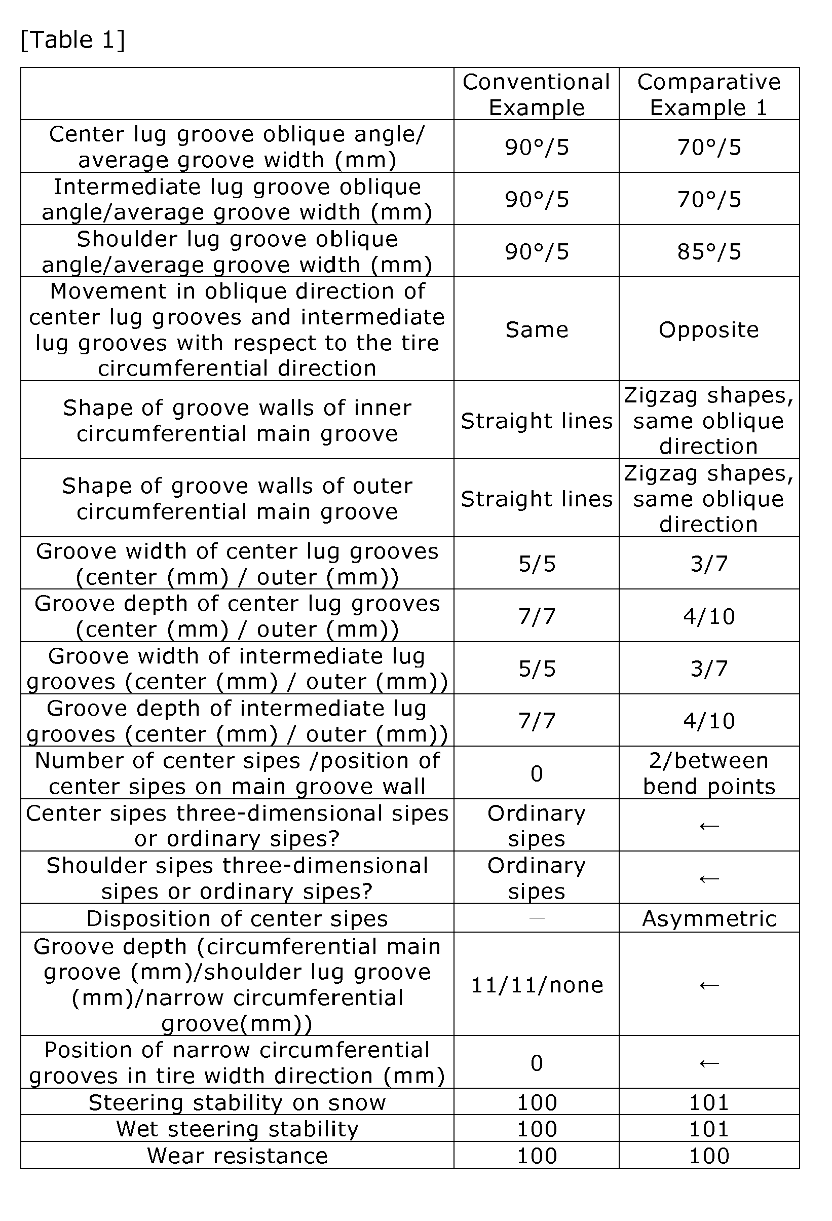

[Table 2] Working Example 4 Working Example 5 Working Example 6 Center lug groove oblique angle/average groove width (mm) 70°/5 70°/4 ← Intermediate lug groove oblique angle/average groove width (mm) 70°/5 70°/4 ← Shoulder lug groove oblique angle/average groove width (mm) 85°/5 85°/6 ← Movement in oblique direction of center lug grooves and intermediate lug grooves with respect to the tire circumferential direction Opposite ← ← Shape of groove walls of inner circumferential main groove Zigzag lines, different oblique direction ← ← Shape of groove walls of outer circumferential main groove Zigzag lines, same oblique direction ← ← Groove width of center lug grooves (center (mm) / outer (mm)) 3/7 ← ← Groove depth of center lug grooves (center (mm) / outer (mm)) 4/10 ← ← Groove width of intermediate lug grooves (center (mm) / outer (mm)) 3/7 ← ← Groove depth of intermediate lug grooves (center (mm) / outer (mm)) 4/10 ← ← Number of center sipes/position of center sipes on main groove wall 2/bend points ← ← Center sipes three-dimensional sipes or ordinary sipes? Three-dimensional sipes ← ← Shoulder sipes three-dimensional sipes or ordinary sipes? Three-dimensional sipes ← ← Disposition of center sipes Symmetric ← ← Groove depth (circumferential main groove (mm)/shoulder lug groove (mm)/narrow circumferential groove(mm)) 11/11/None ← 11/10/5 Position of narrow circumferential grooves in tire width direction (mm) 0 ← 4 Steering stability on snow 105 107 109 Wet steering stability 105 107 109 Wear resistance 104 106 105 - A comparison of Working Example 3 in Table 1 and Working Example 4 in Table 2 shows that wear resistance improved when two center sipes were formed so as to connect the bend points of the main groove walls. A high balance between wear resistance, steering stability on snow, and wet steering stability was obtained when the groove width of the shoulder lug grooves was greater than the groove widths of the center lug grooves and the intermediate lug grooves (Working Examples 5 and 6). Wear resistance was improved and steering stability on snow and wet steering stability were vastly superior when narrow circumferential grooves were present, the grooves having a groove depth less than that of the outer circumferential main grooves and the shoulder lug grooves and intersecting with the shoulder lug grooves on the outer circumferential main groove side with respect to centers in the tire width direction of ground contact regions of the shoulder land portions within a ground contact width of the tire (the ground contact width of the shoulder land portion region) (Working Example 6).
- The foregoing has been a detailed description of the pneumatic tire of the present invention. However, the present invention is naturally not limited to the above embodiments, but may be improved or modified in various ways within the scope of the present invention.
-
- 1 Pneumatic tire
- 2 Tread portion
- 10 Tread pattern
- 11, 13 Outer circumferential main groove
- 15, 17 Inner circumferential main groove
- 12, 12, 14, 14, 16, 16, 18, 18 Pair of main groove walls
- 16a, 18a Bend point in main groove wall of center land portion
- 12 Center land portion
- 23, 25 Intermediate land portion
- 22 Center land portion block
- 24, 26 Intermediate land portion block
- 22a Center of land portion block in center land portion
- 31 Center lug groove
- 33, 35 Intermediate lug groove
- 31B, 33B, 35B Second lug groove region
- 30 Center sipe
- 34, 36 Intermediate sipe
- 51, 53 Shoulder land portion
- 52, 54 Continuous land portion in shoulder land portion
- 61, 63 Shoulder lug groove
- 61A, 63A First region in shoulder lug groove
- 61Ab, 63Ab Groove bottom of first region
- 61B, 63B Second region in shoulder lug groove
- 61Bb, 63Bb Groove bottom in second region of shoulder lug groove
- 61c, 63c Gradient
- 62, 64 Shoulder sipe
- 71, 73 Circumferential narrow groove
- 81, 83 Arc-shaped groove
Claims (16)
- A pneumatic tire comprising a tread pattern formed in a tread portion,
the tread pattern including:a circumferential direction main groove group constituted by four circumferential main grooves parallel to a tire circumferential direction, including two outer circumferential main grooves disposed on an outer side in a tire width direction and two inner circumferential main grooves disposed between the outer circumferential main grooves, a centerline of the tire passing between the inner circumferential main grooves; anda plurality of lug grooves that traverse a region of a center land portion defined by the two inner circumferential main grooves, the center land portion through which the centerline of the tire passes and regions of two intermediate land portions defined by the outer circumferential main grooves and the inner circumferential main grooves, and form a plurality of land portion blocks in the region of the center land portion and the regions of the intermediate land portions;each of the two inner circumferential main grooves comprises a first groove wall and a second groove wall facing the first groove wall;
the first groove wall comprises a first oblique wall element that extends obliquely outward in the tire width direction from a first direction in the tire circumferential direction and a second oblique wall element that extends obliquely inward in the tire width direction from the first direction and extends for a shorter length than the first oblique wall element, the first groove wall being made up of a plurality of sets of first oblique wall elements and second oblique wall elements; and
the second groove wall comprises a third oblique wall element that extends obliquely inward in the tire width direction from the first direction and a fourth oblique wall element that extends obliquely outward in the tire width direction from the first direction and extends for a shorter length than the third oblique wall element, the second groove wall being made up of a plurality of sets of third oblique wall elements and fourth oblique wall elements. - The pneumatic tire according to claim 1, wherein
the first groove wall and the second groove wall of each of the two inner circumferential main grooves are disposed so that two of groove walls of the inner circumferential main grooves contacting the center land portion form a combination of the first groove wall and the second groove wall. - The pneumatic tire according to claim 1 or 2, wherein
the first oblique groove elements and the third oblique groove elements of each of the inner circumferential main grooves are disposed at offset positions in the tire circumferential direction. - The pneumatic tire according to one of claims 1 to 3, wherein
center land portion blocks positioned in the center land portion are each provided with at least two center sipes that extend in parallel with center lug grooves that form the center land portion blocks and connect the two inner circumferential grooves, each of the center sipes extending in a wavy pattern formed by deviations in a direction orthogonal to the center sipe extension direction, and wall surfaces forming the center sipe comprise raised-and-recessed surface portions extending in a wavy pattern formed by deviations toward the bottom of the sipe. - The pneumatic tire according to claim 4, wherein
two center sipes are provided per each of the center land portion blocks, the two center sipes being provided to different sides of the center of the center land portion block with respect to the tire circumferential direction; and
recessed portions of the wavy patterns of the two center sipes face each other with respect to a line that passes through the center and is parallel to the center lug groove, and raised portions of the wavy patterns of the two center sipes face each other with respect to the line. - The pneumatic tire according to any one of claim 1 to 5, wherein
intermediate land portion blocks constituted by land portion blocks in the regions of the intermediate land portions are provided with intermediate sipes that are parallel with intermediate lug grooves that traverse the regions of the intermediate land portions;
shoulder land portions are provided in a region on the outer side in the tire width direction of the circumferential direction main groove group;
the shoulder land portions are provided with shoulder sipes,
the intermediate sipes are sipes that extend in straight or curved lines; and
each of the shoulder sipes comprises a portion that extends in a wavy pattern formed by deviations in a direction orthogonal to the direction in which the shoulder sipe extends, and wall surfaces forming the shoulder sipe comprise a raised-and-recessed surface portion that extends in a wavy pattern formed by deviations toward the bottom of the sipe. - The pneumatic tire according to any one of claims 1 to 5, wherein
shoulder land portions are provided in a region on the outer side in the tire width direction of the circumferential direction main groove group;
each of the shoulder land portion regions is provided with a shoulder lug groove that extends from an outer side in the tire width direction toward one of the outer circumferential main grooves, the shoulder lug groove being closed off along the middle thereof without connecting with either of the outer circumferential main grooves so that the shoulder land portion forms a continuous land portion that continuously extends in the tire circumferential direction; and
the shoulder lug grooves have a groove width that is greater than the maximum groove width of the lug grooves. - The pneumatic tire according to claim 7, wherein
the shoulder lug grooves comprise a first region that extends from an outer end in the tire width direction toward one of the outer circumferential main grooves and a second region that connects with the first region and extends to the closed end of the shoulder lug groove, the second region having a groove depth that is less than that of the first region;
a shoulder sipe extending across the continuous land portion so as to connect to one of the outer circumferential main grooves and the second region of the shoulder lug groove is formed in the regions of the shoulder land portions; and the shoulder sipes have a groove depth that is deeper than that of the second regions of the shoulder lug grooves. - The pneumatic tire according to claim 8, wherein
groove bottom portions in the second regions of the shoulder lug grooves are raised to form gradients so as to be higher than groove bottom portions in the first regions. - The pneumatic tire according to claim 8 or 9, wherein
outer ends of the shoulder sipes in the tire width direction are formed so as to penetrate into the groove bottoms in the second regions of the shoulder lug grooves. - The pneumatic tire according to any one of claims 7 to 10, wherein
narrow circumferential grooves that extend in the tire circumferential direction and have narrower groove widths than the shoulder lug grooves are provided in the shoulder land portion regions;
the narrow circumferential grooves have groove depths that are less than the maximum groove depths of the shoulder lug grooves; and
the narrow circumferential grooves intersect with the shoulder lug grooves on inner sides in the tire width direction with respect to centers in the tire width direction of ground contact regions of the shoulder land portions, the ground contact regions within a ground contact width of the tire. - The pneumatic tire according to claim 11, wherein
the groove depth of the shoulder lug grooves is equal to that of the narrow circumferential grooves at a position where the shoulder lug grooves intersect with the narrow circumferential grooves. - The pneumatic tire according to any one of claims 1 to 12, wherein
arc-shaped grooves that extend in a curving arc so as to connect with the outer circumferential main grooves defining the intermediate land portion blocks and the lug grooves defining the intermediate land portion blocks are formed in the intermediate land portion blocks of the intermediate land portions. - The pneumatic tire according to any one of claims 1 to 13, wherein
at least one of the center lug grooves provided in the center land portion region and the intermediate lug grooves provided in the intermediate land portion region includes a first lug groove region and a second lug groove region that is connected to the first lug groove region, the first lug groove region having a narrower groove width than the second lug groove region and a shallower groove depth than the second lug groove region. - The pneumatic tire according to claim 14, wherein
center lug grooves each including the first lug groove region and the second lug groove region are formed in the center land portion region, the first lug groove region being formed in a central region of the center lug groove in the direction in which the center lug groove extends, the central region traversing the tire centerline, and the second lug groove region being formed on the outer side in the tire width direction of the central region. - The pneumatic tire according to claim 14 or 15, wherein
intermediate lug grooves each including the first lug groove region and the second lug groove region are formed in regions of the intermediate land portions, the first lug groove region being formed on the inner side in the tire width direction of the second lug groove region.
Applications Claiming Priority (2)
| Application Number | Priority Date | Filing Date | Title |
|---|---|---|---|
| JP2013044634 | 2013-03-06 | ||
| PCT/JP2014/051754 WO2014136500A1 (en) | 2013-03-06 | 2014-01-28 | Pneumatic tire |
Publications (3)
| Publication Number | Publication Date |
|---|---|
| EP2913204A1 true EP2913204A1 (en) | 2015-09-02 |
| EP2913204A4 EP2913204A4 (en) | 2016-06-29 |
| EP2913204B1 EP2913204B1 (en) | 2019-04-10 |
Family
ID=51491026
Family Applications (1)
| Application Number | Title | Priority Date | Filing Date |
|---|---|---|---|
| EP14760151.2A Active EP2913204B1 (en) | 2013-03-06 | 2014-01-28 | Pneumatic tire |
Country Status (8)
| Country | Link |
|---|---|
| US (1) | US10286733B2 (en) |
| EP (1) | EP2913204B1 (en) |
| JP (1) | JP5708879B2 (en) |
| KR (1) | KR101659836B1 (en) |
| CN (1) | CN104837653B (en) |
| AU (1) | AU2014227282B2 (en) |
| RU (1) | RU2599856C1 (en) |
| WO (1) | WO2014136500A1 (en) |
Cited By (3)
| Publication number | Priority date | Publication date | Assignee | Title |
|---|---|---|---|---|
| EP3025878B1 (en) * | 2014-11-27 | 2018-06-06 | Sumitomo Rubber Industries Limited | Heavy duty pneumatic tire |
| DE112017002247B4 (en) * | 2016-04-28 | 2021-01-07 | The Yokohama Rubber Co., Ltd. | tire |
| EP3988336A1 (en) * | 2020-10-20 | 2022-04-27 | Sumitomo Rubber Industries, Ltd. | Tire |
Families Citing this family (22)
| Publication number | Priority date | Publication date | Assignee | Title |
|---|---|---|---|---|
| EP3656580B1 (en) * | 2015-02-04 | 2021-03-31 | Bridgestone Corporation | Pneumatic tire |
| JP6206517B2 (en) * | 2016-02-10 | 2017-10-04 | 横浜ゴム株式会社 | Pneumatic tire |
| AU2017244887B2 (en) * | 2016-03-31 | 2019-02-28 | The Yokohama Rubber Co., Ltd. | Heavy-duty pneumatic tire |
| JP6747888B2 (en) * | 2016-06-30 | 2020-08-26 | Toyo Tire株式会社 | Pneumatic tire |
| JP6834291B2 (en) * | 2016-09-21 | 2021-02-24 | 住友ゴム工業株式会社 | Pneumatic tires |
| CN106314041B (en) * | 2016-09-27 | 2018-01-12 | 安徽和鼎轮胎科技股份有限公司 | Exotic performance car tire |
| JP6361763B1 (en) * | 2017-03-06 | 2018-07-25 | 横浜ゴム株式会社 | Pneumatic tire |
| JP6859802B2 (en) * | 2017-03-30 | 2021-04-14 | 住友ゴム工業株式会社 | tire |
| JP6887908B2 (en) * | 2017-07-27 | 2021-06-16 | 株式会社ブリヂストン | tire |
| JP6925227B2 (en) | 2017-10-16 | 2021-08-25 | 株式会社ブリヂストン | tire |
| US11724550B2 (en) * | 2017-11-20 | 2023-08-15 | The Yokohama Rubber Co., Ltd. | Pneumatic tire |
| WO2019189048A1 (en) * | 2018-03-26 | 2019-10-03 | 横浜ゴム株式会社 | Pneumatic tire |
| JP6969474B2 (en) * | 2018-03-26 | 2021-11-24 | 横浜ゴム株式会社 | Pneumatic tires |
| CN108757342B (en) * | 2018-06-04 | 2023-09-08 | 南通理工学院 | Equipment for detecting flaw of fan blade |
| EP3744537B1 (en) * | 2019-05-31 | 2021-12-08 | Sumitomo Rubber Industries, Ltd. | Tire |
| JP2021088344A (en) * | 2019-11-25 | 2021-06-10 | 住友ゴム工業株式会社 | tire |
| JP7460401B2 (en) * | 2020-03-09 | 2024-04-02 | 株式会社ブリヂストン | tire |
| KR102352892B1 (en) * | 2020-08-04 | 2022-01-19 | 넥센타이어 주식회사 | Tire improved plysteer residual aligning torque |
| JP7610971B2 (en) * | 2020-12-21 | 2025-01-09 | Toyo Tire株式会社 | Pneumatic tires |
| JP7561022B2 (en) * | 2020-12-21 | 2024-10-03 | Toyo Tire株式会社 | Pneumatic tires |
| JP7608145B2 (en) * | 2020-12-21 | 2025-01-06 | Toyo Tire株式会社 | Pneumatic tires |
| TWI822255B (en) * | 2022-08-16 | 2023-11-11 | 正新橡膠工業股份有限公司 | Low-noise pneumatic tire suited for wet condition |
Family Cites Families (26)
| Publication number | Priority date | Publication date | Assignee | Title |
|---|---|---|---|---|
| US4807679A (en) * | 1987-06-11 | 1989-02-28 | The Goodyear Tire & Rubber Company | Pneumatic tire tread having sipes |
| JPH01309806A (en) * | 1988-06-07 | 1989-12-14 | Yokohama Rubber Co Ltd:The | Pneumatic tire |
| RU2032549C1 (en) * | 1992-07-30 | 1995-04-10 | Акционерное общество "Проектно-производственное объединение "Старт" | Protector for all-seasonal pneumatic tyres |
| FR2722144B1 (en) * | 1994-07-05 | 1996-09-27 | Michelin & Cie | TIRE TREAD |
| US6427737B1 (en) * | 1998-04-22 | 2002-08-06 | Bridgestone Corporation | Pneumatic tire having at least four sipes |
| JP4149034B2 (en) * | 1998-06-02 | 2008-09-10 | 住友ゴム工業株式会社 | Tires for vehicles |
| DE60023222T2 (en) * | 1999-07-19 | 2006-05-24 | Bridgestone Corp. | tire |
| JP4255229B2 (en) * | 2001-11-28 | 2009-04-15 | 住友ゴム工業株式会社 | Pneumatic tire |
| USD485230S1 (en) * | 2003-02-20 | 2004-01-13 | Michelin Recherche Et Technique | Tire tread |
| WO2006022120A1 (en) * | 2004-08-25 | 2006-03-02 | Bridgestone Corporation | Pneumatic tire |
| JP4422622B2 (en) * | 2005-01-11 | 2010-02-24 | 住友ゴム工業株式会社 | Heavy duty tire |
| JP2007186053A (en) * | 2006-01-12 | 2007-07-26 | Bridgestone Corp | Pneumatic tire |
| JP5038649B2 (en) * | 2006-04-18 | 2012-10-03 | 東洋ゴム工業株式会社 | Pneumatic tire |
| KR100869025B1 (en) * | 2007-07-04 | 2008-11-17 | 금호타이어 주식회사 | Pneumatic tires with variable sipes |
| JP4406454B2 (en) * | 2007-10-10 | 2010-01-27 | 住友ゴム工業株式会社 | Pneumatic tire |
| US8261789B2 (en) * | 2007-10-25 | 2012-09-11 | Continental Tire North America, Inc. | Tire tread having three different sipe types |
| JP4469399B2 (en) * | 2008-03-12 | 2010-05-26 | 住友ゴム工業株式会社 | studless tire |
| JP4488083B2 (en) | 2008-04-11 | 2010-06-23 | 横浜ゴム株式会社 | Pneumatic tire |
| JP4510906B2 (en) * | 2008-05-08 | 2010-07-28 | 住友ゴム工業株式会社 | Pneumatic tire |
| JP5278127B2 (en) * | 2008-06-02 | 2013-09-04 | 横浜ゴム株式会社 | Pneumatic tire |
| JP4428466B2 (en) * | 2008-06-26 | 2010-03-10 | 横浜ゴム株式会社 | Pneumatic tire |
| JP5304127B2 (en) * | 2008-09-16 | 2013-10-02 | 横浜ゴム株式会社 | Pneumatic tire |
| JP5298914B2 (en) | 2009-02-12 | 2013-09-25 | 横浜ゴム株式会社 | Pneumatic tire |
| KR101891985B1 (en) * | 2010-10-08 | 2018-08-27 | 엘지디스플레이 주식회사 | Liquid crystal display device |
| JP5654833B2 (en) * | 2010-10-19 | 2015-01-14 | 住友ゴム工業株式会社 | Pneumatic tire |
| CN203142296U (en) * | 2013-02-08 | 2013-08-21 | 广州市华南橡胶轮胎有限公司 | Tire |
-
2014
- 2014-01-28 WO PCT/JP2014/051754 patent/WO2014136500A1/en not_active Ceased
- 2014-01-28 RU RU2015120372/11A patent/RU2599856C1/en active
- 2014-01-28 CN CN201480003091.2A patent/CN104837653B/en active Active
- 2014-01-28 US US14/648,684 patent/US10286733B2/en active Active
- 2014-01-28 JP JP2014506663A patent/JP5708879B2/en active Active
- 2014-01-28 KR KR1020157010214A patent/KR101659836B1/en active Active
- 2014-01-28 EP EP14760151.2A patent/EP2913204B1/en active Active
- 2014-01-28 AU AU2014227282A patent/AU2014227282B2/en active Active
Cited By (3)
| Publication number | Priority date | Publication date | Assignee | Title |
|---|---|---|---|---|
| EP3025878B1 (en) * | 2014-11-27 | 2018-06-06 | Sumitomo Rubber Industries Limited | Heavy duty pneumatic tire |
| DE112017002247B4 (en) * | 2016-04-28 | 2021-01-07 | The Yokohama Rubber Co., Ltd. | tire |
| EP3988336A1 (en) * | 2020-10-20 | 2022-04-27 | Sumitomo Rubber Industries, Ltd. | Tire |
Also Published As
| Publication number | Publication date |
|---|---|
| WO2014136500A1 (en) | 2014-09-12 |
| AU2014227282B2 (en) | 2016-03-17 |
| KR101659836B1 (en) | 2016-09-26 |
| JP5708879B2 (en) | 2015-04-30 |
| US20150298508A1 (en) | 2015-10-22 |
| JPWO2014136500A1 (en) | 2017-02-09 |
| CN104837653B (en) | 2017-03-29 |
| CN104837653A (en) | 2015-08-12 |
| EP2913204A4 (en) | 2016-06-29 |
| KR20150060811A (en) | 2015-06-03 |
| AU2014227282A1 (en) | 2015-06-04 |
| RU2599856C1 (en) | 2016-10-20 |
| US10286733B2 (en) | 2019-05-14 |
| EP2913204B1 (en) | 2019-04-10 |
Similar Documents
| Publication | Publication Date | Title |
|---|---|---|
| EP2913204B1 (en) | Pneumatic tire | |
| EP2915684B1 (en) | Pneumatic tire | |
| US10894446B2 (en) | Tire | |
| EP3178668B1 (en) | Pneumatic tire | |
| US10449807B2 (en) | Pneumatic tire | |
| US10668774B2 (en) | Pneumatic tire | |
| CN108382134B (en) | Tyre for vehicle wheels | |
| US8925602B2 (en) | Pneumatic tire | |
| US10328751B2 (en) | Pneumatic tire | |
| US9855801B2 (en) | Pneumatic tire | |
| US9555669B2 (en) | Pneumatic tire | |
| EP2614966A1 (en) | Heavy duty pneumatic tire | |
| US10780743B2 (en) | Tire | |
| US20160297249A1 (en) | Pneumatic tire | |
| CN106142997A (en) | Pneumatic tire | |
| EP2602127B1 (en) | Tire | |
| US20170313135A1 (en) | Pneumatic Tire | |
| EP3572244A1 (en) | Tire | |
| JP7176320B2 (en) | tire | |
| US11890897B2 (en) | Pneumatic tire | |
| WO2021002209A1 (en) | Pneumatic tire | |
| US20220258539A1 (en) | Tyre | |
| JP4255229B2 (en) | Pneumatic tire | |
| US10239356B2 (en) | Pneumatic tire |
Legal Events
| Date | Code | Title | Description |
|---|---|---|---|
| PUAI | Public reference made under article 153(3) epc to a published international application that has entered the european phase |
Free format text: ORIGINAL CODE: 0009012 |
|
| 17P | Request for examination filed |
Effective date: 20150529 |
|
| AK | Designated contracting states |
Kind code of ref document: A1 Designated state(s): AL AT BE BG CH CY CZ DE DK EE ES FI FR GB GR HR HU IE IS IT LI LT LU LV MC MK MT NL NO PL PT RO RS SE SI SK SM TR |
|
| AX | Request for extension of the european patent |
Extension state: BA ME |
|
| REG | Reference to a national code |
Ref country code: DE Ref legal event code: R079 Ref document number: 602014044488 Country of ref document: DE Free format text: PREVIOUS MAIN CLASS: B60C0011040000 Ipc: B60C0011030000 |
|
| DAX | Request for extension of the european patent (deleted) | ||
| RA4 | Supplementary search report drawn up and despatched (corrected) |
Effective date: 20160527 |
|
| RIC1 | Information provided on ipc code assigned before grant |
Ipc: B60C 11/11 20060101ALI20160520BHEP Ipc: B60C 11/13 20060101ALI20160520BHEP Ipc: B60C 11/03 20060101AFI20160520BHEP Ipc: B60C 11/12 20060101ALI20160520BHEP Ipc: B60C 11/04 20060101ALI20160520BHEP |
|
| STAA | Information on the status of an ep patent application or granted ep patent |
Free format text: STATUS: EXAMINATION IS IN PROGRESS |
|
| 17Q | First examination report despatched |
Effective date: 20180104 |
|
| GRAP | Despatch of communication of intention to grant a patent |
Free format text: ORIGINAL CODE: EPIDOSNIGR1 |
|
| STAA | Information on the status of an ep patent application or granted ep patent |
Free format text: STATUS: GRANT OF PATENT IS INTENDED |
|
| INTG | Intention to grant announced |
Effective date: 20181025 |
|
| GRAS | Grant fee paid |
Free format text: ORIGINAL CODE: EPIDOSNIGR3 |
|
| GRAA | (expected) grant |
Free format text: ORIGINAL CODE: 0009210 |
|
| STAA | Information on the status of an ep patent application or granted ep patent |
Free format text: STATUS: THE PATENT HAS BEEN GRANTED |
|
| AK | Designated contracting states |
Kind code of ref document: B1 Designated state(s): AL AT BE BG CH CY CZ DE DK EE ES FI FR GB GR HR HU IE IS IT LI LT LU LV MC MK MT NL NO PL PT RO RS SE SI SK SM TR |
|
| REG | Reference to a national code |
Ref country code: GB Ref legal event code: FG4D |
|
| REG | Reference to a national code |
Ref country code: CH Ref legal event code: EP Ref country code: AT Ref legal event code: REF Ref document number: 1118138 Country of ref document: AT Kind code of ref document: T Effective date: 20190415 |
|
| REG | Reference to a national code |
Ref country code: IE Ref legal event code: FG4D |
|
| REG | Reference to a national code |
Ref country code: DE Ref legal event code: R096 Ref document number: 602014044488 Country of ref document: DE |
|
| REG | Reference to a national code |
Ref country code: NL Ref legal event code: MP Effective date: 20190410 |
|
| REG | Reference to a national code |
Ref country code: LT Ref legal event code: MG4D |
|
| REG | Reference to a national code |
Ref country code: AT Ref legal event code: MK05 Ref document number: 1118138 Country of ref document: AT Kind code of ref document: T Effective date: 20190410 |
|
| PG25 | Lapsed in a contracting state [announced via postgrant information from national office to epo] |
Ref country code: NL Free format text: LAPSE BECAUSE OF FAILURE TO SUBMIT A TRANSLATION OF THE DESCRIPTION OR TO PAY THE FEE WITHIN THE PRESCRIBED TIME-LIMIT Effective date: 20190410 |
|
| PG25 | Lapsed in a contracting state [announced via postgrant information from national office to epo] |
Ref country code: SE Free format text: LAPSE BECAUSE OF FAILURE TO SUBMIT A TRANSLATION OF THE DESCRIPTION OR TO PAY THE FEE WITHIN THE PRESCRIBED TIME-LIMIT Effective date: 20190410 Ref country code: AL Free format text: LAPSE BECAUSE OF FAILURE TO SUBMIT A TRANSLATION OF THE DESCRIPTION OR TO PAY THE FEE WITHIN THE PRESCRIBED TIME-LIMIT Effective date: 20190410 Ref country code: FI Free format text: LAPSE BECAUSE OF FAILURE TO SUBMIT A TRANSLATION OF THE DESCRIPTION OR TO PAY THE FEE WITHIN THE PRESCRIBED TIME-LIMIT Effective date: 20190410 Ref country code: LT Free format text: LAPSE BECAUSE OF FAILURE TO SUBMIT A TRANSLATION OF THE DESCRIPTION OR TO PAY THE FEE WITHIN THE PRESCRIBED TIME-LIMIT Effective date: 20190410 Ref country code: PT Free format text: LAPSE BECAUSE OF FAILURE TO SUBMIT A TRANSLATION OF THE DESCRIPTION OR TO PAY THE FEE WITHIN THE PRESCRIBED TIME-LIMIT Effective date: 20190910 Ref country code: NO Free format text: LAPSE BECAUSE OF FAILURE TO SUBMIT A TRANSLATION OF THE DESCRIPTION OR TO PAY THE FEE WITHIN THE PRESCRIBED TIME-LIMIT Effective date: 20190710 Ref country code: HR Free format text: LAPSE BECAUSE OF FAILURE TO SUBMIT A TRANSLATION OF THE DESCRIPTION OR TO PAY THE FEE WITHIN THE PRESCRIBED TIME-LIMIT Effective date: 20190410 Ref country code: ES Free format text: LAPSE BECAUSE OF FAILURE TO SUBMIT A TRANSLATION OF THE DESCRIPTION OR TO PAY THE FEE WITHIN THE PRESCRIBED TIME-LIMIT Effective date: 20190410 |
|
| PG25 | Lapsed in a contracting state [announced via postgrant information from national office to epo] |
Ref country code: LV Free format text: LAPSE BECAUSE OF FAILURE TO SUBMIT A TRANSLATION OF THE DESCRIPTION OR TO PAY THE FEE WITHIN THE PRESCRIBED TIME-LIMIT Effective date: 20190410 Ref country code: RS Free format text: LAPSE BECAUSE OF FAILURE TO SUBMIT A TRANSLATION OF THE DESCRIPTION OR TO PAY THE FEE WITHIN THE PRESCRIBED TIME-LIMIT Effective date: 20190410 Ref country code: BG Free format text: LAPSE BECAUSE OF FAILURE TO SUBMIT A TRANSLATION OF THE DESCRIPTION OR TO PAY THE FEE WITHIN THE PRESCRIBED TIME-LIMIT Effective date: 20190710 Ref country code: PL Free format text: LAPSE BECAUSE OF FAILURE TO SUBMIT A TRANSLATION OF THE DESCRIPTION OR TO PAY THE FEE WITHIN THE PRESCRIBED TIME-LIMIT Effective date: 20190410 Ref country code: GR Free format text: LAPSE BECAUSE OF FAILURE TO SUBMIT A TRANSLATION OF THE DESCRIPTION OR TO PAY THE FEE WITHIN THE PRESCRIBED TIME-LIMIT Effective date: 20190711 |
|
| PG25 | Lapsed in a contracting state [announced via postgrant information from national office to epo] |
Ref country code: IS Free format text: LAPSE BECAUSE OF FAILURE TO SUBMIT A TRANSLATION OF THE DESCRIPTION OR TO PAY THE FEE WITHIN THE PRESCRIBED TIME-LIMIT Effective date: 20190810 Ref country code: AT Free format text: LAPSE BECAUSE OF FAILURE TO SUBMIT A TRANSLATION OF THE DESCRIPTION OR TO PAY THE FEE WITHIN THE PRESCRIBED TIME-LIMIT Effective date: 20190410 |
|
| REG | Reference to a national code |
Ref country code: DE Ref legal event code: R097 Ref document number: 602014044488 Country of ref document: DE |
|
| PG25 | Lapsed in a contracting state [announced via postgrant information from national office to epo] |
Ref country code: CZ Free format text: LAPSE BECAUSE OF FAILURE TO SUBMIT A TRANSLATION OF THE DESCRIPTION OR TO PAY THE FEE WITHIN THE PRESCRIBED TIME-LIMIT Effective date: 20190410 Ref country code: RO Free format text: LAPSE BECAUSE OF FAILURE TO SUBMIT A TRANSLATION OF THE DESCRIPTION OR TO PAY THE FEE WITHIN THE PRESCRIBED TIME-LIMIT Effective date: 20190410 Ref country code: DK Free format text: LAPSE BECAUSE OF FAILURE TO SUBMIT A TRANSLATION OF THE DESCRIPTION OR TO PAY THE FEE WITHIN THE PRESCRIBED TIME-LIMIT Effective date: 20190410 Ref country code: EE Free format text: LAPSE BECAUSE OF FAILURE TO SUBMIT A TRANSLATION OF THE DESCRIPTION OR TO PAY THE FEE WITHIN THE PRESCRIBED TIME-LIMIT Effective date: 20190410 Ref country code: SK Free format text: LAPSE BECAUSE OF FAILURE TO SUBMIT A TRANSLATION OF THE DESCRIPTION OR TO PAY THE FEE WITHIN THE PRESCRIBED TIME-LIMIT Effective date: 20190410 |
|
| PLBE | No opposition filed within time limit |
Free format text: ORIGINAL CODE: 0009261 |
|
| STAA | Information on the status of an ep patent application or granted ep patent |
Free format text: STATUS: NO OPPOSITION FILED WITHIN TIME LIMIT |
|
| PG25 | Lapsed in a contracting state [announced via postgrant information from national office to epo] |
Ref country code: IT Free format text: LAPSE BECAUSE OF FAILURE TO SUBMIT A TRANSLATION OF THE DESCRIPTION OR TO PAY THE FEE WITHIN THE PRESCRIBED TIME-LIMIT Effective date: 20190410 Ref country code: SM Free format text: LAPSE BECAUSE OF FAILURE TO SUBMIT A TRANSLATION OF THE DESCRIPTION OR TO PAY THE FEE WITHIN THE PRESCRIBED TIME-LIMIT Effective date: 20190410 |
|
| 26N | No opposition filed |
Effective date: 20200113 |
|
| PG25 | Lapsed in a contracting state [announced via postgrant information from national office to epo] |
Ref country code: TR Free format text: LAPSE BECAUSE OF FAILURE TO SUBMIT A TRANSLATION OF THE DESCRIPTION OR TO PAY THE FEE WITHIN THE PRESCRIBED TIME-LIMIT Effective date: 20190410 |
|
| PG25 | Lapsed in a contracting state [announced via postgrant information from national office to epo] |
Ref country code: SI Free format text: LAPSE BECAUSE OF FAILURE TO SUBMIT A TRANSLATION OF THE DESCRIPTION OR TO PAY THE FEE WITHIN THE PRESCRIBED TIME-LIMIT Effective date: 20190410 |
|
| PG25 | Lapsed in a contracting state [announced via postgrant information from national office to epo] |
Ref country code: MC Free format text: LAPSE BECAUSE OF FAILURE TO SUBMIT A TRANSLATION OF THE DESCRIPTION OR TO PAY THE FEE WITHIN THE PRESCRIBED TIME-LIMIT Effective date: 20190410 |
|
| REG | Reference to a national code |
Ref country code: CH Ref legal event code: PL |
|
| GBPC | Gb: european patent ceased through non-payment of renewal fee |
Effective date: 20200128 |
|
| REG | Reference to a national code |
Ref country code: BE Ref legal event code: MM Effective date: 20200131 |
|
| PG25 | Lapsed in a contracting state [announced via postgrant information from national office to epo] |
Ref country code: FR Free format text: LAPSE BECAUSE OF NON-PAYMENT OF DUE FEES Effective date: 20200131 Ref country code: LU Free format text: LAPSE BECAUSE OF NON-PAYMENT OF DUE FEES Effective date: 20200128 Ref country code: GB Free format text: LAPSE BECAUSE OF NON-PAYMENT OF DUE FEES Effective date: 20200128 |
|
| PG25 | Lapsed in a contracting state [announced via postgrant information from national office to epo] |
Ref country code: BE Free format text: LAPSE BECAUSE OF NON-PAYMENT OF DUE FEES Effective date: 20200131 Ref country code: CH Free format text: LAPSE BECAUSE OF NON-PAYMENT OF DUE FEES Effective date: 20200131 Ref country code: LI Free format text: LAPSE BECAUSE OF NON-PAYMENT OF DUE FEES Effective date: 20200131 |
|
| PG25 | Lapsed in a contracting state [announced via postgrant information from national office to epo] |
Ref country code: IE Free format text: LAPSE BECAUSE OF NON-PAYMENT OF DUE FEES Effective date: 20200128 |
|
| PG25 | Lapsed in a contracting state [announced via postgrant information from national office to epo] |
Ref country code: MT Free format text: LAPSE BECAUSE OF FAILURE TO SUBMIT A TRANSLATION OF THE DESCRIPTION OR TO PAY THE FEE WITHIN THE PRESCRIBED TIME-LIMIT Effective date: 20190410 Ref country code: CY Free format text: LAPSE BECAUSE OF FAILURE TO SUBMIT A TRANSLATION OF THE DESCRIPTION OR TO PAY THE FEE WITHIN THE PRESCRIBED TIME-LIMIT Effective date: 20190410 |
|
| PG25 | Lapsed in a contracting state [announced via postgrant information from national office to epo] |
Ref country code: MK Free format text: LAPSE BECAUSE OF FAILURE TO SUBMIT A TRANSLATION OF THE DESCRIPTION OR TO PAY THE FEE WITHIN THE PRESCRIBED TIME-LIMIT Effective date: 20190410 |
|
| P01 | Opt-out of the competence of the unified patent court (upc) registered |
Effective date: 20230512 |
|
| PGFP | Annual fee paid to national office [announced via postgrant information from national office to epo] |
Ref country code: DE Payment date: 20241203 Year of fee payment: 12 |