EP2876735B1 - Steckverbinder für Mittel- und Niederspannungsanwendung - Google Patents
Steckverbinder für Mittel- und Niederspannungsanwendung Download PDFInfo
- Publication number
- EP2876735B1 EP2876735B1 EP13193871.4A EP13193871A EP2876735B1 EP 2876735 B1 EP2876735 B1 EP 2876735B1 EP 13193871 A EP13193871 A EP 13193871A EP 2876735 B1 EP2876735 B1 EP 2876735B1
- Authority
- EP
- European Patent Office
- Prior art keywords
- housing
- connecting means
- connector
- terminal
- chamber
- Prior art date
- Legal status (The legal status is an assumption and is not a legal conclusion. Google has not performed a legal analysis and makes no representation as to the accuracy of the status listed.)
- Active
Links
- 239000004020 conductor Substances 0.000 claims description 20
- 239000012777 electrically insulating material Substances 0.000 claims description 5
- 239000000463 material Substances 0.000 description 5
- 230000008602 contraction Effects 0.000 description 3
- 210000001331 nose Anatomy 0.000 description 3
- 238000005452 bending Methods 0.000 description 2
- 239000013536 elastomeric material Substances 0.000 description 2
- 210000000887 face Anatomy 0.000 description 2
- 210000003128 head Anatomy 0.000 description 2
- 239000012212 insulator Substances 0.000 description 2
- 238000004519 manufacturing process Methods 0.000 description 2
- 239000002184 metal Substances 0.000 description 2
- 238000000034 method Methods 0.000 description 2
- 229920002943 EPDM rubber Polymers 0.000 description 1
- 238000004026 adhesive bonding Methods 0.000 description 1
- 230000006378 damage Effects 0.000 description 1
- 230000001419 dependent effect Effects 0.000 description 1
- 239000011810 insulating material Substances 0.000 description 1
- 239000004033 plastic Substances 0.000 description 1
- 229920003023 plastic Polymers 0.000 description 1
- 229920001296 polysiloxane Polymers 0.000 description 1
- 230000002787 reinforcement Effects 0.000 description 1
- 230000000717 retained effect Effects 0.000 description 1
- 239000007779 soft material Substances 0.000 description 1
- 229920001169 thermoplastic Polymers 0.000 description 1
- 229920002725 thermoplastic elastomer Polymers 0.000 description 1
- 239000012815 thermoplastic material Substances 0.000 description 1
Images


Classifications
-
- H—ELECTRICITY
- H01—ELECTRIC ELEMENTS
- H01R—ELECTRICALLY-CONDUCTIVE CONNECTIONS; STRUCTURAL ASSOCIATIONS OF A PLURALITY OF MUTUALLY-INSULATED ELECTRICAL CONNECTING ELEMENTS; COUPLING DEVICES; CURRENT COLLECTORS
- H01R13/00—Details of coupling devices of the kinds covered by groups H01R12/70 or H01R24/00 - H01R33/00
- H01R13/46—Bases; Cases
- H01R13/53—Bases or cases for heavy duty; Bases or cases for high voltage with means for preventing corona or arcing
-
- H—ELECTRICITY
- H01—ELECTRIC ELEMENTS
- H01R—ELECTRICALLY-CONDUCTIVE CONNECTIONS; STRUCTURAL ASSOCIATIONS OF A PLURALITY OF MUTUALLY-INSULATED ELECTRICAL CONNECTING ELEMENTS; COUPLING DEVICES; CURRENT COLLECTORS
- H01R25/00—Coupling parts adapted for simultaneous co-operation with two or more identical counterparts, e.g. for distributing energy to two or more circuits
- H01R25/16—Rails or bus-bars provided with a plurality of discrete connecting locations for counterparts
- H01R25/161—Details
- H01R25/162—Electrical connections between or with rails or bus-bars
-
- H—ELECTRICITY
- H02—GENERATION; CONVERSION OR DISTRIBUTION OF ELECTRIC POWER
- H02G—INSTALLATION OF ELECTRIC CABLES OR LINES, OR OF COMBINED OPTICAL AND ELECTRIC CABLES OR LINES
- H02G15/00—Cable fittings
- H02G15/08—Cable junctions
Definitions
- the present invention relates to a connector for medium and low voltage application according to claim 1.
- EP 0 147 979 B1 describes a connector for medium and low voltage application with a housing made of an electrically insulating material.
- the housing may become inappropriately soft when the plugs are taken off during an exchange procedure. Also, when plugs are positioned in the housing, the plugs might be exposed to high mechanical loads which can lead to failure of the plugs or inappropriate deformation of the housing and failure of the electrical interfaces.
- WO 91/11040 discloses a connector with a housing with a first chamber for receiving a first terminal and at least a part of a second terminal and a second terminal, wherein the first chamber is embodied to receive an inner plug, wherein the inner plug is provided for electrically connecting the first terminal with the second terminal, wherein the housing comprises a connecting means that is fixed with the housing, wherein the connecting means is arranged in the first chamber, wherein the connecting means is provided for a connection with the first terminal.
- the object of the invention is to provide a connector for medium and low voltage application with an improved mechanical stability.
- the object of the invention is attained by the connector according to claim 1.
- a connector for medium and low voltage application with a housing wherein the housing comprises connecting means.
- the connecting means ensures that the connector can be strongly fixed with a first terminal and that the connector cannot be easily removed from the first terminal. Furthermore, the position of the housing relative to the first terminal is determined more precisely.
- the connecting means sustains a stable position of the connector housing referring to the first terminal.
- This is for example of advantage for an elbow housing for an elbow connector.
- the connecting means holds the housing and especially the chambers for the plugs in a predefined position and/or shape. Therefore, less mechanical stress may be induced in the housing and in the plugs.
- the plugs can be taken off the connector and the housing of the connector is strongly fixed to the first terminal and stays in the predetermined position. As a result, less stress is induced in the housing when the plugs are removed.
- the plugs can be mounted to the housing more easily since the housing and the chambers for the plugs stay in the predetermined position and/or shape. External elements such as fixing means of a housing or a wall of an electrical equipment are not necessary to fix the connector at the electrical equipment.
- Further connecting means is arranged at an outer face of the housing and the housing.
- the further connecting means has the shape of a shell that covers at least a part of the face of the housing.
- This embodiment provides a simple and stable further connecting means.
- the shell may be made of one or more than one part that encompasses the housing at least partially and keeps the housing in a predetermined shape.
- the shell may also be embodied in order to clamp the first and the second part of the housing and to hold the first and the second part in a predetermined position.
- the first chamber of the housing comprises an inner rim that is assigned to the first connecting means, wherein the inner rim abuts on a face of the first connecting means that is assigned to the first chamber, wherein the inner rim defines a diameter of the first chamber that is smaller than the cross section of the first connecting means perpendicular to the first axis. Therefore, it is necessary to expand the inner rim over an outer face of the first connecting means to remove the housing from the first terminal. Higher force is necessary to pull the housing from the first terminal.
- the further connecting means comprise fixing means for fixing the shell to the housing, wherein the fixing means is for example form fit means.
- the connecting means is arranged in the housing and protrudes at least partly from a first chamber of the housing.
- the first chamber of the housing is provided for receiving a first terminal, for example a bushing of an electrical equipment.
- the connecting means is additionally used as an electrical connecting member between the bushing and an inner plug that connects the bushing with a second electrical terminal.
- the connecting means comprises contact sections for connecting the connecting means with the first terminal and with an inner plug.
- the connecting means has the shape of a plate for example with a hole, wherein the hole is arranged in the first chamber and the plate is fixed to the housing.
- the hole is used as a connection section between the first terminal and the plate and between the inner plug and the plate.
- the plate may be form-fit fixed to the housing.
- the plate is partly arranged in a recess of the housing.
- the connecting means may have the shape of a plate and a pin that is connected with the plate.
- the pin comprises at a free end a contact section for electrically and mechanically connecting the first terminal that may be embodied as a bushing of an electrical equipment.
- the shell may comprise a fixing means for fixing the shell to a wall or a housing of an electrical equipment.
- a fixing means for fixing the shell to a wall or a housing of an electrical equipment.
- the connector may be an elbow connector with an angle between 10° and 170°, preferably with an angle of 90°. Especially, for elbow connectors, a stable shape is necessary.
- the further connecting means and/or the fixing means is arranged in an area of the inner rim.
- the connecting means and/or the fixing means clamps the housing to the first connecting means and hampers the expanding of the inner rim. Therefore, higher forces are necessary to pull the housing off the first terminal.
- an outer plug is provided in the first chamber adjacent to the inner plug.
- the outer plug is used as a closure element.
- the outer plug is made of electrically insulating material.
- the outer plug is at least partially made of electrically conducting material and is used for electrically connecting the inner plug with a further electrical conductor.
- the further conductor may be a cable that is connected to the connector, i.e. with the inner plug and/or the second terminal.
- FIG. 1 shows a cross sectional view of a first embodiment of the connector 25.
- the connector 25 comprises a housing 1.
- the housing 1 comprises a first chamber 2 and a second chamber 3.
- the first chamber 2 is arranged along a first axis 5.
- the second chamber 3 is arranged along a second axis 6 with a predetermined angle to the first axis 5.
- the predetermined angle may vary between 10° and 170°.
- the second axis 6 is arranged in a 90°-angle referring to the first axis 5.
- the first chamber 2 is provided for receiving a first terminal 40 that may be embodied as a bushing of an electrical equipment 46.
- the bushing 40 may comprise a first conductor 44 that is covered by an insulator 45.
- the second chamber 3 is embodied for receiving a second terminal 50; the second terminal 50 is for example embodied as a conductor 52 being surrounded by an insulating material.
- the first chamber 2 is arranged along the first axis 5 and open at two opposite ends of a base part 60 of the housing 1.
- the base part 60 has a longitudinal shape along the first axis 5.
- a dome 65 protrudes laterally from the base part 60.
- the dome 65 is arranged along the second axis 6, has the shape of a sleeve and comprises the second chamber 3.
- the base part 60 and the dome 65 are arranged in one piece.
- the base part 60 and the dome 65 may be separate pieces. In other embodiments there may be more than one dome arranged in one or more pieces.
- a first section 21 of the first chamber 2 is provided for receiving the first terminal 40.
- the first section 21 ends at a first connecting means 4.
- the first connecting means 4 is constructed as a plate that is fixed with the housing 1 and that is partly arranged in a recess 61 of the housing 1 and in the first chamber 2.
- the first chamber 2 comprises an inner rim 26 that is assigned to the first connecting means 4.
- the inner rim 26 defines a cross section of the first chamber 2 adjacent to the first supporting means 4.
- the first supporting means 4 has a larger cross section than the diameter of the inner rim 26.
- the inner rim 26 abuts on a face of the first supporting means 4 and defines an overlap that is assigned to the first chamber 2.
- the inner rim 26 prevents an easy removing of the housing from the first terminal 40.
- the inner rim 26 may have the shape of a circular overlap.
- the first connecting means 4 separates the first section 21 of the first chamber 2 from a second section 22 of the first chamber 2.
- the second section 22 extends from the first connecting means 4 in the direction of the second axis 6 to a predetermined distance beyond the second axis 6.
- the second section 22 is provided for receiving an inner plug 20.
- the inner plug 20 may be made of an electrically conducting material.
- the inner plug 20 is used for electrically connecting the first terminal 40 with the second terminal 50.
- the second terminal 50 comprises a contact ring 51 that encircles the first chamber 2 in a plane of the second axis 6.
- the contact ring 51 is electrically connected to a conductor 52.
- the conductor 52 may be a conductor of a cable. Different shapes of the contact ring 51 are possible.
- the shape of the contact ring 51 may relate e.g. to the design of the electrical contact to the inner plug 20.
- a third section 23 follows the second section 22.
- the third section 23 extends to a first end face 62 of the base part 60 of the housing 1.
- the third section 23 is provided for receiving an outer plug 30 that may be made of an electrically insulating material.
- the outer plug 30 is fixed to the base part 60 of the housing 1 and holds the inner plug 20 in the predetermined position. In a mounted position, the inner plug 20 may extend through the contact ring 51 of the second terminal 50.
- the first connecting means 4 comprises contact sections 42, 43 for electrically and mechanically connecting the first terminal 40 to the first connecting means 4 and the inner plug 20 to the first connecting means 4.
- the first connecting means 4 is screwed into e.g. the first conductor 44 with at least one screw 47.
- the screw 47 is bolted to a thread 48 of the first conductor 44.
- the inner plug 20 comprises a threaded section 21 that is screwed to a thread of the hole 80 of the plate 4.
- the housing 1 may be made of an elastomeric material, for example silicone, TPE or EPDM.
- the first connecting means 4 may be made of metal or another electrically conducting material that comprises a higher shore hardness than the material of the housing 1. Since the first connecting means 4 is connected to the first terminal 40 and fixed in the housing 1, a stable position of the housing 1 is attained also in the case that the inner plug 20 and the outer plug 30 are taken off for example during an exchange procedure of the second terminal 50. Additionally, the shape of the housing 1 is supported by the first connecting means 4 when the inner plug 20 and the outer plug 30 are in the mounted position. Therefore, less stress is induced in the inner plug 20 and the connection between the inner plug 20 and the second terminal 50.
- the housing 1 with a bending and the shape of an elbow is retained on the first terminal 40 that may be embodied as a bushing. Due to the first connecting means 4, pull-off forces that are sufficient to pull off the housing 1 from the first terminal 40 are increased remarkably. Depending on the used design of the first connecting means 4, the housing 1 may be prevented from any pull-off without material destruction of the housing 1.
- Figure 2 shows a further embodiment of a connector 25 that comprises the features of the housing 1 of Figure 1 and additionally a second connecting means 7.
- the second connecting means 7 is made of a shell that covers at least a part of the outer face of the housing 1.
- the second connecting means 7 may be embodied in one part or in several parts that are connected to each other or fixed to the housing for example by mechanical means such as form fit and/or force fit and/or face fit or gluing.
- the second connecting means 7 may be made of metal, duroplastic plastics, thermoplastic or elastomeric material with a higher shore hardness, for example higher than A50 with or without reinforcement structure.
- the second connecting means 7 may have a higher hardness than the material of the housing 1.
- the second connecting means 7 is constructed as a ring shell 79 that is arranged in the region of the first connecting means 4.
- the ring shell 79 encompasses the base part 60 of the housing 1.
- the first and second fixing means 8, 9 are form-fit shapes of the ring shell 79 and the housing 1.
- the housing 1 comprises as second fixing means undercuts 9, in which noses 8 of the ring shell 79 are arranged as first fixing means.
- the ring shell 79 may comprise openings in which noses of the housing 1 project.
- the first and second fixing means 8, 9 fix the second connecting means 7 to the housing 1.
- the first fixing means 8 can also be designed as a ring that is arranged in a plane perpendicular to the first axis 5.
- the second fixing means 9 is embodied as a circular undercut that surrounds the base part 60 in a plane that is arranged perpendicular to the first axis 5.
- the first fixing means 8 retains the housing 1 that may be made of a soft material in a circular shape.
- the first fixing means 8 and the ring shell 79 may be embodied in one piece or as separate pieces.
- the first fixing means 8 is arranged at a first radial distance 28 to an outer face 29 of the first supporting means 4.
- the first fixing means 8 is arranged at a second radial distance 27 to an inner rim 26 of the base part 60.
- the inner rim 26 defines the cross section of the first chamber 2 adjacent to the first supporting means 4.
- the inner rim 26 abuts on the first supporting means 4. If the housing 1 is to be removed from the first terminal 40 then the inner rim 26 has to be pulled over the broader outer face 29 of the first supporting means 4. Due to the first fixing means 8 a higher force is necessary to expand the inner rim 26 over the first supporting means 4.
- the ring shell 79 may be constructed as one piece or in two pieces in a half-shell design or may comprise more than two pieces.
- the ring shell 79 may be made of continuous blanks or may have a number of openings when being formed of whole blanks or the like.
- Figure 3 shows a further embodiment of the connector 25 with a housing 1 that comprises the features of the embodiment of figure 2 , wherein the second connecting means 7 is constructed as a longitudinal sleeve 78 that compared to the embodiment of figure 2 covers a longer section of the base housing 60 including the section at which the dome 65 protrudes from the base housing 60. Therefore, it is possible to support the predetermined shape of the housing 1 along the first axis 5 and along the second axis 6 for a larger length than the design shown in figure 2 . Therefore, the predetermined angle of the bending of the housing and the angle between the first and the second axis 5, 6 is supported by the second connecting means 7.
- the sleeve 78 comprises an opening 72 through which the dome 64 of the housing 1 is guided.
- the sleeve 78 comprises a circular wall section 73 that surrounds at least a section of the dome 65 adjacent to the base housing 60. Therefore the dome 65 is held in the predetermined position i.e. an angle referring to the longitudinal axis 5 of the base housing 60. The longer the wall section 73 is the stronger is the fixing of the dome 65 in the predetermined position. Depending on the used embodiment, the wall section 73 may be omitted and there may be only an opening 72 for the dome 65.
- the sleeve 78 covers at least a part of the first section 21 and a part of the second section 22.
- the sleeve 78 may cover a part of the first section 21 and the second section 22 and at least a part of the third section 23. The longer the sleeve 78 is the stronger is the supporting of the shape of the housing 1.
- the first connecting means may be omitted and only the second connecting means 7, 79 may be provided.
- Figure 4 shows a further embodiment of a connector 25 with a housing 1 that is embodied as shown in figure 3 and with a second connecting means 7 in the shape of a sleeve 78, whereby the sleeve 78 is guided with an end section 74 to a first end face 62 of the base part 60 of the housing 1.
- the sleeve 78 comprises circular abut faces 71 that comprise a further fixing means 10.
- the abut faces 71 are provided for abutting against a further housing, for example a housing of an electrical equipment 46 that comprises the bushing 40.
- the further fixing means 10 is provided for fixing the sleeve 78 to a housing of an electrical equipment 46 or a wall.
- the further fixing means 10 may be configured as holes for receiving screws to bolt the sleeve 78 to the housing of an electrical equipment 46.
- the base part 60 comprises a further recess 77 at the first part of the second section 22.
- the first recess 77 circumvents the base part 60 in a plane perpendicular to the first axis 5.
- the sleeve 78 has at least one nose or a lateral contraction 75 that is arranged at the further recess 77.
- the contraction 75 fixes the housing to the second connecting means 7. As a result, the housing 1 can be strongly fixed to the electrical equipment 46.
- Figure 5 shows a top view on a first embodiment of a first connecting means 4 that is constructed as a circular first plate 11.
- a dashed line 83 is shown on the first plate 11 that defines an outer rim that is arranged in a recess of the housing 1 in the mounted position.
- the first plate 11 comprises a circular hole 80.
- the first plate 11 is embodied as a circular ring plate with a central hole 80.
- the hole 80 has two sections 81, 82 as shown in Figure 6 .
- a first section 81 has a larger diameter than a second section 82.
- the hole 80 has a circular shape with different diameters in the different sections 81, 82.
- the first section may comprise a thread for receiving a thread bolt of the inner plug 20.
- the second section 82 may also comprise a thread for receiving a thread bolt of the first terminal 40.
- the second section may also be embodied as a hole to receive a bolt that is screwed in a thread of the first terminal 40.
- Figure 7 shows an embodiment of the first connecting means that is constructed as a further plate 14, wherein a circular side face 84 of the further plate 14 is arranged inclined with an angle to a symmetry axis 85. This reduces the amount of material and/or allows for a slim design of the housing 1 in this area.
- Figure 8 shows a further embodiment of the first connecting means that is embodied as a second plate 12.
- the second plate 12 has the basic shape of a rectangular plate with rounded edges.
- the hole 80 is embodied as shown in Figure 6 .
- the dashed line 83 defines a circle and determines an outer rim that is arranged in a recess of the housing 1.
- Figure 9 shows a further embodiment of the first connecting means embodied as a third plate 13.
- the third plate 13 has a polygon shape with rounded edges.
- the third plate 13 comprises two holes 86, 87, whereby the two holes may comprise threads that are used for mechanically and electrically connecting threaded pins of the inner plug 20 and the first terminal 40.
- the second hole 87 may be used for connecting and fixing the first terminal 40.
- the first hole 86 may be used for connecting the inner plug 20.
- the two holes 86, 87 have a predetermined distance A.
- an outer rim of the third plate 13 is covered by the housing 1.
- the dashed line 83 defines a circle around the second hole 87 and determines an outer rim that is arranged in a recess of the housing 1. Further embodiments are possible which have more than one hole 86 to allow to have housings 1 with more than one plug 20.
- Figure 10 shows a further embodiment of the first plate 11 that comprises a further pin 89 with a thread 48.
- the pin 89 and the plate 11 are made in one piece and made of electrically conducting material.
- Figure 11 shows another embodiment of the first plate 11, wherein between the first and third section 81, 82 a third section 88 is arranged.
- the third section 88 is provided for receiving a head of a screw.
- the screw is used for mechanically and electrically connecting the first plate 11 with the first terminal 40.
- the embodiment of figure 12 shows a further first plate 11 that provides a space within the first section 81 for receiving a head of a screw.
- the connecting means for example the first, second, third or fourth plate 11, 12, 13, 14 may be mounted in the housing 1 after the production of the housing 1 or the connecting means is molded in mold material during the production of the housing 1.
- the connecting means is axially symmetrically to the first axis, then depending on the used embodiment the connecting means may be rotatable arranged in the housing 1.
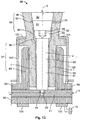
- Figure 13 shows a section of a further embodiment of a connector 25 with a housing 1 and a base part 60 with a first dome 65.
- the first dome 65 surrounds the housing 1 with a first chamber 2.
- a terminal is arranged which is an electrical conductor and for example embodied as a busbar 41.
- the busbar 41 may have a rectangular cross section in a plane perpendicular to the first axis 5.
- the first chamber 2 is arranged along the second axis 6.
- the first dome 65 is arranged along the second axis 6 that is aligned in a predetermined angle to the first axis 5. In the shown embodiment, the second axis 6 of the first dome 65is perpendicular to the first axis 5.
- the first dome 65 encompasses an end section 97 of a housing 1.
- the housing 1 may basically have the shape of a sleeve.
- the end section 97 has the shape of a sleeve and is arranged within the first dome 65.
- a third connecting means 90 is arranged in the end section 97.
- the third connecting means 90 comprises a pin 91 with a plate 92 at one end and a thread bolt 93 at the other end.
- the pin 91 is arranged along the second axis 6.
- the plate 92 is arranged perpendicular to the second axis 6.
- the thread bolt 93 is screwed in a screw thread 94 of the busbar 41.
- the third connecting means 90 fixes the housing 1 to the dome 65.
- a lower circular side 95 of the plate 92 abuts on an upper circular ring face 96 of the housing 1.
- the end section 97 of the housing 1 has a smaller inner diameter than an upper section 98 of the housing 1.
- the end section 97 passes to the upper section 98 via the upper ring face 96.
- the diameter of the plate 92 is larger than the diameter of the end section 97. Therefore the lower side 95 of the plate 92 holds the housing 1 at the dome 65.
- the inner plug 20 On the upper side of the plate 92, the inner plug 20 abuts and connects the contact ring 51 of the second terminal 50. The inner plug 20 is pressed to the plate 92 by the outer plug 30.
- the fourth connecting means 100 may be embodied as a shell that covers at least partly with the shape of a ring the base part 60 and that encompasses at least partly with the shape of a ring the housing 1.
- the housing 1 comprises at least one recess 99.
- a rim 101 of the fourth connecting means 100 protrudes in the recess 99. Therefore, the fourth connecting means 100 additionally fixes the housing 1 to the base part 60.
- the recess 99 may be arranged at a level of the end section 97.
- the recess 99 may have a circular shape.
- the rim 101 may have a circular shape that encompasses the end section 97 protruding in the circular recess 99.
- the second dome 66 has a conical shape and is encircled by an end section 97 of a housing 1.
- the housing 1 has basically the shape of a sleeve.
- the pin 91 is arranged along the second axis 6.
- the plate 92 is arranged perpendicular to the second axis 6.
- a free end of the pin 91 comprises a thread bolt 93 that is screwed in a screw thread 94 of the bus bar 41.
- an inner plug 20 may be arranged that electrically connects the plate 92 with a second terminal 50 as for example shown in Figure 1 .
- an outer plug 30 may be arranged in the first chamber 2 within the housing 1. The outer plug 30 may close the first chamber 2. The outer plug may be in contact with the inner plug.
- the outer plug may be made of electrically insulating material or may be made at least partly of an electrically conducting material. An electrically conducting outer plug may be used for electrically connecting the inner plug and/or the second terminal with a further conductor.
- the fourth connecting means 100 covers the outer face of the base part 60 and additionally the outer face of the first dome 65and at least partly a circular section of the housing 1.
- the third or the fourth connecting means 90, 100 may be omitted in the shown embodiment of Figure 13 .
- the described connector may be used for medium voltage application in the range of 1000 to 72 000 volt and for currents in the range of up to 250A, 630A, 1250A or more. Depending on the used embodiment, the described connectors may be used for low voltage applications in the range below 1 kV.
Landscapes
- Connector Housings Or Holding Contact Members (AREA)
Claims (8)
- Steckverbinder (25) für Mittel- und Niederspannungsanwendungen mit einem Gehäuse (1) mit einer ersten Kammer (2) zur Aufnahme eines ersten Anschlusses (40) und zumindest eines Teils eines zweiten Anschlusses (50), wobei die erste Kammer (2) dazu ausgelegt ist, einen inneren Stecker (20) aufzunehmen, wobei der innere Stecker (20) bereitgestellt ist, um den ersten Anschluss (40) mit dem zweiten Anschluss (50) elektrisch zu verbinden, wobei das Gehäuse (1) eine Verbindungseinrichtung (4) umfasst, die am Gehäuse (1) befestigt ist, wobei die Verbindungseinrichtung (4) zumindest teilweise in der ersten Kammer (2) angeordnet ist, wobei die Verbindungseinrichtung (4) zur Verbindung mit dem ersten Anschluss (40) bereitgestellt ist, wobei die Verbindungseinrichtung (4) die mechanische Verbindung zwischen dem ersten Anschluss (40) und dem Gehäuse (1) verbessert,
wobei die erste Kammer (2) des Gehäuses (1) einen Innenrand (26) umfasst, der der ersten Verbindungseinrichtung (4) zugeordnet ist, wobei der Innenrand (26) an einer Fläche der ersten Verbindungseinrichtung (4), die der ersten Kammer (2) zugeordnet ist, anschlägt, wobei der Innenrand (26) einen Durchmesser der ersten Kammer (2) definiert, der kleiner als der Querschnitt der ersten Verbindungseinrichtung (4) senkrecht zur ersten Achse (5) ist, wobei der Innenrand (26) über eine Außenfläche (29) der ersten Verbindungseinrichtung (4) erweitert werden muss, um das Gehäuse (1) aus dem ersten Anschluss (40) zu entfernen,
dadurch gekennzeichnet, dass eine weitere Verbindungseinrichtung (7, 100) an einer Außenfläche des Gehäuses (1) angeordnet ist, wobei die weitere Verbindungseinrichtung die Form einer Ummantelung (7, 100) aufweist, die zumindest einen Teil der Fläche des Gehäuses (1) bedeckt, wobei die Ummantelung (7, 70) an der Außenfläche des Gehäuses (1) in einem Bereich des Innenrands (26) angeordnet ist, wobei die weitere Verbindungseinrichtung (7, 100) eine Befestigungseinrichtung (8, 9, 101) zum Befestigen der weiteren Verbindungseinrichtung (7, 100) am Gehäuse umfasst, wobei die Befestigungseinrichtung (8, 9, 101) zum Beispiel eine Formschlusseinrichtung ist. - Steckverbinder nach Anspruch 1, wobei die Verbindungseinrichtung (4) die Form einer Platte (11, 12, 13, 14) aufweist.
- Steckverbinder nach einem der Ansprüche 1 oder 2, wobei die weitere Verbindungseinrichtung (7, 70, 100) eine Einrichtung (10) zum Befestigen der Verbindungseinrichtung (7, 70, 100) und des Gehäuses (1) an einer Wand oder elektrischen Anlage (46) umfasst.
- Steckverbinder nach einem der vorstehenden Ansprüche, wobei der Steckverbinder (25) ein Winkelstecker ist und der erste und zweite Anschluss (40, 41, 50) in einem Winkel zwischen 10° und 170°, vorzugsweise in einem Winkel von 90°, zueinander angeordnet sind.
- Steckverbinder nach einem der vorstehenden Ansprüche, wobei die Befestigungseinrichtung (8, 9) an einer Außenfläche des Gehäuses (1) in einem Bereich des Innenrands (26) angeordnet ist.
- Steckverbinder nach einem der vorstehenden Ansprüche, wobei ein äußerer Stecker (30) in der ersten Kammer (2) an den inneren Stecker (20) angrenzend bereitgestellt ist.
- Steckverbinder nach Anspruch 6, wobei der äußere Stecker (30) aus einem elektrisch isolierenden Material hergestellt ist.
- Steckverbinder nach Anspruch 6, wobei der äußere Stecker (30) zumindest teilweise aus einem elektrisch leitfähigen Material hergestellt ist und zum Verbinden des inneren Steckers (20) mit einem weiteren Leiter bereitgestellt ist.
Priority Applications (5)
| Application Number | Priority Date | Filing Date | Title |
|---|---|---|---|
| EP13193871.4A EP2876735B1 (de) | 2013-11-21 | 2013-11-21 | Steckverbinder für Mittel- und Niederspannungsanwendung |
| BR112016010993-7A BR112016010993B1 (pt) | 2013-11-21 | 2014-11-20 | Conector para aplicação de tensão média e baixa |
| AU2014351902A AU2014351902B2 (en) | 2013-11-21 | 2014-11-20 | Connector for medium and low voltage application |
| CN201480063329.0A CN105765793B (zh) | 2013-11-21 | 2014-11-20 | 用于中压和低压应用的连接器 |
| PCT/EP2014/075100 WO2015075112A1 (en) | 2013-11-21 | 2014-11-20 | Connector for medium and low voltage application |
Applications Claiming Priority (1)
| Application Number | Priority Date | Filing Date | Title |
|---|---|---|---|
| EP13193871.4A EP2876735B1 (de) | 2013-11-21 | 2013-11-21 | Steckverbinder für Mittel- und Niederspannungsanwendung |
Publications (2)
| Publication Number | Publication Date |
|---|---|
| EP2876735A1 EP2876735A1 (de) | 2015-05-27 |
| EP2876735B1 true EP2876735B1 (de) | 2019-08-07 |
Family
ID=49619844
Family Applications (1)
| Application Number | Title | Priority Date | Filing Date |
|---|---|---|---|
| EP13193871.4A Active EP2876735B1 (de) | 2013-11-21 | 2013-11-21 | Steckverbinder für Mittel- und Niederspannungsanwendung |
Country Status (5)
| Country | Link |
|---|---|
| EP (1) | EP2876735B1 (de) |
| CN (1) | CN105765793B (de) |
| AU (1) | AU2014351902B2 (de) |
| BR (1) | BR112016010993B1 (de) |
| WO (1) | WO2015075112A1 (de) |
Citations (1)
| Publication number | Priority date | Publication date | Assignee | Title |
|---|---|---|---|---|
| WO2011061074A1 (en) * | 2009-11-23 | 2011-05-26 | Tyco Electronics France Sas | Casing for an electrical connector |
Family Cites Families (6)
| Publication number | Priority date | Publication date | Assignee | Title |
|---|---|---|---|---|
| GB2154382B (en) | 1983-12-14 | 1988-04-07 | Raychem Ltd | High voltage connector |
| US4799895A (en) * | 1987-06-22 | 1989-01-24 | Amerace Corporation | 600-Amp hot stick operable screw-assembled connector system |
| GB9000488D0 (en) * | 1990-01-09 | 1990-03-07 | Raychem Gmbh | Cable connector |
| DE19845776A1 (de) * | 1998-09-22 | 2000-03-23 | Siemens Ag | T-förmige Verbindungsanschlüsse für gasisolierte Mittelspannungsschaltanlagen |
| CN2483850Y (zh) * | 2001-05-04 | 2002-03-27 | 莫列斯公司 | 电连接器屏蔽装置 |
| DE10140762A1 (de) * | 2001-08-20 | 2003-03-06 | Efen Gmbh | Elektrischer T-Stecker |
-
2013
- 2013-11-21 EP EP13193871.4A patent/EP2876735B1/de active Active
-
2014
- 2014-11-20 WO PCT/EP2014/075100 patent/WO2015075112A1/en active Application Filing
- 2014-11-20 BR BR112016010993-7A patent/BR112016010993B1/pt active IP Right Grant
- 2014-11-20 CN CN201480063329.0A patent/CN105765793B/zh active Active
- 2014-11-20 AU AU2014351902A patent/AU2014351902B2/en active Active
Patent Citations (1)
| Publication number | Priority date | Publication date | Assignee | Title |
|---|---|---|---|---|
| WO2011061074A1 (en) * | 2009-11-23 | 2011-05-26 | Tyco Electronics France Sas | Casing for an electrical connector |
Also Published As
| Publication number | Publication date |
|---|---|
| BR112016010993B1 (pt) | 2022-12-06 |
| WO2015075112A1 (en) | 2015-05-28 |
| CN105765793B (zh) | 2018-02-02 |
| BR112016010993A2 (de) | 2017-08-08 |
| AU2014351902A1 (en) | 2016-07-07 |
| CN105765793A (zh) | 2016-07-13 |
| EP2876735A1 (de) | 2015-05-27 |
| AU2014351902B2 (en) | 2019-01-31 |
Similar Documents
| Publication | Publication Date | Title |
|---|---|---|
| EP2469671B1 (de) | Klemmring, Kabelstopfen und Verfahren zur Einpassung eines Kabelstopfens | |
| CN102792530B (zh) | 壁式hf组件 | |
| US7393252B2 (en) | Female electrical contact element and method for making a female electrical contact element | |
| KR102461548B1 (ko) | 밸브 코어 | |
| EP2961004A1 (de) | Koaxialer elektrischer hochfrequenzverbinder mit kontaktelement | |
| TWM488766U (zh) | 插接器 | |
| US3571781A (en) | Plastic cable clamp | |
| EP2239816B1 (de) | Elektrischer Stecker und Herstellungsverfahren dafür | |
| US10084248B2 (en) | Freely translatable electrical connection device having protection against damage from foreign bodies | |
| EP2876735B1 (de) | Steckverbinder für Mittel- und Niederspannungsanwendung | |
| US5498179A (en) | Electrical connector | |
| CN107534233B (zh) | 蓄电池接线柱和用于制造蓄电池接线柱的方法 | |
| JP2018206590A (ja) | 端子金具 | |
| KR102249090B1 (ko) | Pe-접점을 갖는 장착 프레임 | |
| KR102106208B1 (ko) | 차폐 케이블용 단자 조립체 | |
| CN215521563U (zh) | 支撑元件 | |
| KR20170117693A (ko) | 커넥터 | |
| KR20110012578A (ko) | 온도감지용 압착단자 | |
| KR200366950Y1 (ko) | 배전선로용 전선 분기접속구의 결합구조 | |
| EP2876734B1 (de) | Verbinderbaugruppe | |
| NL1040319C2 (en) | Electrical connector and vehicle provided therewith. | |
| CN110896180B (zh) | 联接耦合装置、存储系统以及带有联接耦合装置的机动车 | |
| EP3573198B1 (de) | Leitfähige verbindung | |
| EP2658042B1 (de) | Steckverbinder | |
| JP2018049683A (ja) | コネクタ付ケーブル |
Legal Events
| Date | Code | Title | Description |
|---|---|---|---|
| PUAI | Public reference made under article 153(3) epc to a published international application that has entered the european phase |
Free format text: ORIGINAL CODE: 0009012 |
|
| 17P | Request for examination filed |
Effective date: 20131121 |
|
| AK | Designated contracting states |
Kind code of ref document: A1 Designated state(s): AL AT BE BG CH CY CZ DE DK EE ES FI FR GB GR HR HU IE IS IT LI LT LU LV MC MK MT NL NO PL PT RO RS SE SI SK SM TR |
|
| AX | Request for extension of the european patent |
Extension state: BA ME |
|
| R17P | Request for examination filed (corrected) |
Effective date: 20151126 |
|
| RBV | Designated contracting states (corrected) |
Designated state(s): AL AT BE BG CH CY CZ DE DK EE ES FI FR GB GR HR HU IE IS IT LI LT LU LV MC MK MT NL NO PL PT RO RS SE SI SK SM TR |
|
| 17Q | First examination report despatched |
Effective date: 20160704 |
|
| STAA | Information on the status of an ep patent application or granted ep patent |
Free format text: STATUS: EXAMINATION IS IN PROGRESS |
|
| GRAP | Despatch of communication of intention to grant a patent |
Free format text: ORIGINAL CODE: EPIDOSNIGR1 |
|
| STAA | Information on the status of an ep patent application or granted ep patent |
Free format text: STATUS: GRANT OF PATENT IS INTENDED |
|
| INTG | Intention to grant announced |
Effective date: 20190311 |
|
| GRAS | Grant fee paid |
Free format text: ORIGINAL CODE: EPIDOSNIGR3 |
|
| GRAA | (expected) grant |
Free format text: ORIGINAL CODE: 0009210 |
|
| STAA | Information on the status of an ep patent application or granted ep patent |
Free format text: STATUS: THE PATENT HAS BEEN GRANTED |
|
| AK | Designated contracting states |
Kind code of ref document: B1 Designated state(s): AL AT BE BG CH CY CZ DE DK EE ES FI FR GB GR HR HU IE IS IT LI LT LU LV MC MK MT NL NO PL PT RO RS SE SI SK SM TR |
|
| REG | Reference to a national code |
Ref country code: GB Ref legal event code: FG4D |
|
| REG | Reference to a national code |
Ref country code: CH Ref legal event code: EP Ref country code: AT Ref legal event code: REF Ref document number: 1165260 Country of ref document: AT Kind code of ref document: T Effective date: 20190815 |
|
| REG | Reference to a national code |
Ref country code: DE Ref legal event code: R096 Ref document number: 602013058722 Country of ref document: DE |
|
| REG | Reference to a national code |
Ref country code: IE Ref legal event code: FG4D |
|
| REG | Reference to a national code |
Ref country code: NL Ref legal event code: MP Effective date: 20190807 |
|
| REG | Reference to a national code |
Ref country code: LT Ref legal event code: MG4D |
|
| PG25 | Lapsed in a contracting state [announced via postgrant information from national office to epo] |
Ref country code: NO Free format text: LAPSE BECAUSE OF FAILURE TO SUBMIT A TRANSLATION OF THE DESCRIPTION OR TO PAY THE FEE WITHIN THE PRESCRIBED TIME-LIMIT Effective date: 20191107 Ref country code: NL Free format text: LAPSE BECAUSE OF FAILURE TO SUBMIT A TRANSLATION OF THE DESCRIPTION OR TO PAY THE FEE WITHIN THE PRESCRIBED TIME-LIMIT Effective date: 20190807 Ref country code: BG Free format text: LAPSE BECAUSE OF FAILURE TO SUBMIT A TRANSLATION OF THE DESCRIPTION OR TO PAY THE FEE WITHIN THE PRESCRIBED TIME-LIMIT Effective date: 20191107 Ref country code: SE Free format text: LAPSE BECAUSE OF FAILURE TO SUBMIT A TRANSLATION OF THE DESCRIPTION OR TO PAY THE FEE WITHIN THE PRESCRIBED TIME-LIMIT Effective date: 20190807 Ref country code: LT Free format text: LAPSE BECAUSE OF FAILURE TO SUBMIT A TRANSLATION OF THE DESCRIPTION OR TO PAY THE FEE WITHIN THE PRESCRIBED TIME-LIMIT Effective date: 20190807 Ref country code: HR Free format text: LAPSE BECAUSE OF FAILURE TO SUBMIT A TRANSLATION OF THE DESCRIPTION OR TO PAY THE FEE WITHIN THE PRESCRIBED TIME-LIMIT Effective date: 20190807 Ref country code: PT Free format text: LAPSE BECAUSE OF FAILURE TO SUBMIT A TRANSLATION OF THE DESCRIPTION OR TO PAY THE FEE WITHIN THE PRESCRIBED TIME-LIMIT Effective date: 20191209 Ref country code: FI Free format text: LAPSE BECAUSE OF FAILURE TO SUBMIT A TRANSLATION OF THE DESCRIPTION OR TO PAY THE FEE WITHIN THE PRESCRIBED TIME-LIMIT Effective date: 20190807 |
|
| REG | Reference to a national code |
Ref country code: AT Ref legal event code: MK05 Ref document number: 1165260 Country of ref document: AT Kind code of ref document: T Effective date: 20190807 |
|
| PG25 | Lapsed in a contracting state [announced via postgrant information from national office to epo] |
Ref country code: ES Free format text: LAPSE BECAUSE OF FAILURE TO SUBMIT A TRANSLATION OF THE DESCRIPTION OR TO PAY THE FEE WITHIN THE PRESCRIBED TIME-LIMIT Effective date: 20190807 Ref country code: GR Free format text: LAPSE BECAUSE OF FAILURE TO SUBMIT A TRANSLATION OF THE DESCRIPTION OR TO PAY THE FEE WITHIN THE PRESCRIBED TIME-LIMIT Effective date: 20191108 Ref country code: RS Free format text: LAPSE BECAUSE OF FAILURE TO SUBMIT A TRANSLATION OF THE DESCRIPTION OR TO PAY THE FEE WITHIN THE PRESCRIBED TIME-LIMIT Effective date: 20190807 Ref country code: IS Free format text: LAPSE BECAUSE OF FAILURE TO SUBMIT A TRANSLATION OF THE DESCRIPTION OR TO PAY THE FEE WITHIN THE PRESCRIBED TIME-LIMIT Effective date: 20191207 Ref country code: LV Free format text: LAPSE BECAUSE OF FAILURE TO SUBMIT A TRANSLATION OF THE DESCRIPTION OR TO PAY THE FEE WITHIN THE PRESCRIBED TIME-LIMIT Effective date: 20190807 Ref country code: AL Free format text: LAPSE BECAUSE OF FAILURE TO SUBMIT A TRANSLATION OF THE DESCRIPTION OR TO PAY THE FEE WITHIN THE PRESCRIBED TIME-LIMIT Effective date: 20190807 |
|
| PG25 | Lapsed in a contracting state [announced via postgrant information from national office to epo] |
Ref country code: TR Free format text: LAPSE BECAUSE OF FAILURE TO SUBMIT A TRANSLATION OF THE DESCRIPTION OR TO PAY THE FEE WITHIN THE PRESCRIBED TIME-LIMIT Effective date: 20190807 |
|
| PG25 | Lapsed in a contracting state [announced via postgrant information from national office to epo] |
Ref country code: IT Free format text: LAPSE BECAUSE OF FAILURE TO SUBMIT A TRANSLATION OF THE DESCRIPTION OR TO PAY THE FEE WITHIN THE PRESCRIBED TIME-LIMIT Effective date: 20190807 Ref country code: RO Free format text: LAPSE BECAUSE OF FAILURE TO SUBMIT A TRANSLATION OF THE DESCRIPTION OR TO PAY THE FEE WITHIN THE PRESCRIBED TIME-LIMIT Effective date: 20190807 Ref country code: AT Free format text: LAPSE BECAUSE OF FAILURE TO SUBMIT A TRANSLATION OF THE DESCRIPTION OR TO PAY THE FEE WITHIN THE PRESCRIBED TIME-LIMIT Effective date: 20190807 Ref country code: EE Free format text: LAPSE BECAUSE OF FAILURE TO SUBMIT A TRANSLATION OF THE DESCRIPTION OR TO PAY THE FEE WITHIN THE PRESCRIBED TIME-LIMIT Effective date: 20190807 Ref country code: PL Free format text: LAPSE BECAUSE OF FAILURE TO SUBMIT A TRANSLATION OF THE DESCRIPTION OR TO PAY THE FEE WITHIN THE PRESCRIBED TIME-LIMIT Effective date: 20190807 Ref country code: DK Free format text: LAPSE BECAUSE OF FAILURE TO SUBMIT A TRANSLATION OF THE DESCRIPTION OR TO PAY THE FEE WITHIN THE PRESCRIBED TIME-LIMIT Effective date: 20190807 |
|
| PG25 | Lapsed in a contracting state [announced via postgrant information from national office to epo] |
Ref country code: SK Free format text: LAPSE BECAUSE OF FAILURE TO SUBMIT A TRANSLATION OF THE DESCRIPTION OR TO PAY THE FEE WITHIN THE PRESCRIBED TIME-LIMIT Effective date: 20190807 Ref country code: SM Free format text: LAPSE BECAUSE OF FAILURE TO SUBMIT A TRANSLATION OF THE DESCRIPTION OR TO PAY THE FEE WITHIN THE PRESCRIBED TIME-LIMIT Effective date: 20190807 Ref country code: IS Free format text: LAPSE BECAUSE OF FAILURE TO SUBMIT A TRANSLATION OF THE DESCRIPTION OR TO PAY THE FEE WITHIN THE PRESCRIBED TIME-LIMIT Effective date: 20200224 Ref country code: CZ Free format text: LAPSE BECAUSE OF FAILURE TO SUBMIT A TRANSLATION OF THE DESCRIPTION OR TO PAY THE FEE WITHIN THE PRESCRIBED TIME-LIMIT Effective date: 20190807 |
|
| REG | Reference to a national code |
Ref country code: DE Ref legal event code: R097 Ref document number: 602013058722 Country of ref document: DE |
|
| REG | Reference to a national code |
Ref country code: CH Ref legal event code: PL |
|
| PLBE | No opposition filed within time limit |
Free format text: ORIGINAL CODE: 0009261 |
|
| STAA | Information on the status of an ep patent application or granted ep patent |
Free format text: STATUS: NO OPPOSITION FILED WITHIN TIME LIMIT |
|
| PG2D | Information on lapse in contracting state deleted |
Ref country code: IS |
|
| PG25 | Lapsed in a contracting state [announced via postgrant information from national office to epo] |
Ref country code: LI Free format text: LAPSE BECAUSE OF NON-PAYMENT OF DUE FEES Effective date: 20191130 Ref country code: LU Free format text: LAPSE BECAUSE OF NON-PAYMENT OF DUE FEES Effective date: 20191121 Ref country code: MC Free format text: LAPSE BECAUSE OF FAILURE TO SUBMIT A TRANSLATION OF THE DESCRIPTION OR TO PAY THE FEE WITHIN THE PRESCRIBED TIME-LIMIT Effective date: 20190807 Ref country code: CH Free format text: LAPSE BECAUSE OF NON-PAYMENT OF DUE FEES Effective date: 20191130 |
|
| 26N | No opposition filed |
Effective date: 20200603 |
|
| REG | Reference to a national code |
Ref country code: BE Ref legal event code: MM Effective date: 20191130 |
|
| PG25 | Lapsed in a contracting state [announced via postgrant information from national office to epo] |
Ref country code: SI Free format text: LAPSE BECAUSE OF FAILURE TO SUBMIT A TRANSLATION OF THE DESCRIPTION OR TO PAY THE FEE WITHIN THE PRESCRIBED TIME-LIMIT Effective date: 20190807 |
|
| PG25 | Lapsed in a contracting state [announced via postgrant information from national office to epo] |
Ref country code: IE Free format text: LAPSE BECAUSE OF NON-PAYMENT OF DUE FEES Effective date: 20191121 |
|
| PG25 | Lapsed in a contracting state [announced via postgrant information from national office to epo] |
Ref country code: BE Free format text: LAPSE BECAUSE OF NON-PAYMENT OF DUE FEES Effective date: 20191130 |
|
| PG25 | Lapsed in a contracting state [announced via postgrant information from national office to epo] |
Ref country code: CY Free format text: LAPSE BECAUSE OF FAILURE TO SUBMIT A TRANSLATION OF THE DESCRIPTION OR TO PAY THE FEE WITHIN THE PRESCRIBED TIME-LIMIT Effective date: 20190807 |
|
| PG25 | Lapsed in a contracting state [announced via postgrant information from national office to epo] |
Ref country code: HU Free format text: LAPSE BECAUSE OF FAILURE TO SUBMIT A TRANSLATION OF THE DESCRIPTION OR TO PAY THE FEE WITHIN THE PRESCRIBED TIME-LIMIT; INVALID AB INITIO Effective date: 20131121 Ref country code: MT Free format text: LAPSE BECAUSE OF FAILURE TO SUBMIT A TRANSLATION OF THE DESCRIPTION OR TO PAY THE FEE WITHIN THE PRESCRIBED TIME-LIMIT Effective date: 20190807 |
|
| PG25 | Lapsed in a contracting state [announced via postgrant information from national office to epo] |
Ref country code: MK Free format text: LAPSE BECAUSE OF FAILURE TO SUBMIT A TRANSLATION OF THE DESCRIPTION OR TO PAY THE FEE WITHIN THE PRESCRIBED TIME-LIMIT Effective date: 20190807 |
|
| PGFP | Annual fee paid to national office [announced via postgrant information from national office to epo] |
Ref country code: FR Payment date: 20240909 Year of fee payment: 12 |
|
| PGFP | Annual fee paid to national office [announced via postgrant information from national office to epo] |
Ref country code: DE Payment date: 20240925 Year of fee payment: 12 |
|
| PGFP | Annual fee paid to national office [announced via postgrant information from national office to epo] |
Ref country code: GB Payment date: 20241001 Year of fee payment: 12 |