EP2611088A1 - Digital communications receiver - Google Patents
Digital communications receiver Download PDFInfo
- Publication number
- EP2611088A1 EP2611088A1 EP13161694.8A EP13161694A EP2611088A1 EP 2611088 A1 EP2611088 A1 EP 2611088A1 EP 13161694 A EP13161694 A EP 13161694A EP 2611088 A1 EP2611088 A1 EP 2611088A1
- Authority
- EP
- European Patent Office
- Prior art keywords
- signal
- values
- symbols
- frequency domain
- symbol
- Prior art date
- Legal status (The legal status is an assumption and is not a legal conclusion. Google has not performed a legal analysis and makes no representation as to the accuracy of the status listed.)
- Granted
Links
Images


Classifications
-
- H—ELECTRICITY
- H04—ELECTRIC COMMUNICATION TECHNIQUE
- H04L—TRANSMISSION OF DIGITAL INFORMATION, e.g. TELEGRAPHIC COMMUNICATION
- H04L25/00—Baseband systems
- H04L25/02—Details ; arrangements for supplying electrical power along data transmission lines
- H04L25/03—Shaping networks in transmitter or receiver, e.g. adaptive shaping networks
- H04L25/03006—Arrangements for removing intersymbol interference
- H04L25/03171—Arrangements involving maximum a posteriori probability [MAP] detection
-
- H—ELECTRICITY
- H04—ELECTRIC COMMUNICATION TECHNIQUE
- H04L—TRANSMISSION OF DIGITAL INFORMATION, e.g. TELEGRAPHIC COMMUNICATION
- H04L27/00—Modulated-carrier systems
- H04L27/02—Amplitude-modulated carrier systems, e.g. using on-off keying; Single sideband or vestigial sideband modulation
- H04L27/04—Modulator circuits; Transmitter circuits
-
- H—ELECTRICITY
- H04—ELECTRIC COMMUNICATION TECHNIQUE
- H04L—TRANSMISSION OF DIGITAL INFORMATION, e.g. TELEGRAPHIC COMMUNICATION
- H04L25/00—Baseband systems
- H04L25/02—Details ; arrangements for supplying electrical power along data transmission lines
- H04L25/03—Shaping networks in transmitter or receiver, e.g. adaptive shaping networks
- H04L25/03006—Arrangements for removing intersymbol interference
- H04L2025/0335—Arrangements for removing intersymbol interference characterised by the type of transmission
- H04L2025/03375—Passband transmission
- H04L2025/03382—Single of vestigal sideband
-
- H—ELECTRICITY
- H04—ELECTRIC COMMUNICATION TECHNIQUE
- H04L—TRANSMISSION OF DIGITAL INFORMATION, e.g. TELEGRAPHIC COMMUNICATION
- H04L25/00—Baseband systems
- H04L25/02—Details ; arrangements for supplying electrical power along data transmission lines
- H04L25/03—Shaping networks in transmitter or receiver, e.g. adaptive shaping networks
- H04L25/03006—Arrangements for removing intersymbol interference
- H04L2025/03433—Arrangements for removing intersymbol interference characterised by equaliser structure
- H04L2025/03439—Fixed structures
- H04L2025/03522—Frequency domain
-
- H—ELECTRICITY
- H04—ELECTRIC COMMUNICATION TECHNIQUE
- H04L—TRANSMISSION OF DIGITAL INFORMATION, e.g. TELEGRAPHIC COMMUNICATION
- H04L25/00—Baseband systems
- H04L25/02—Details ; arrangements for supplying electrical power along data transmission lines
- H04L25/0202—Channel estimation
- H04L25/0212—Channel estimation of impulse response
Definitions
- DTV digital television
- Transmitting digital information typically involves converting the digital information to an analog signal and modulating an RF (radio frequency) carrier frequency's amplitude and/or phase using the analog signal, and sending the modulated signal over a propagation medium.
- RF radio frequency
- a communications system 200 includes a transmitter 202 and a receiver 204.
- the transmitter 202 and the receiver 204 have respective antennas 206, 208, here shown externally to the transmitter 202 and the receiver 204, although the antennas 206, 208 may be considered to be parts of the transmitter 202 and the receiver 204.
- the transmitter 202 is configured to send information over a propagation medium, here a terrestrial broadcast system, to the receiver 204. Transmitting information over the propagation medium introduces signal distortion caused by noise w(t) (e.g., static), strength variations (fading), phase shift variations, multiple path delays, etc.
- noise w(t) e.g., static
- fading strength variations
- phase shift variations e.g., multiple path delays, etc.
- Multiple path delays result from the transmitted signals taking different paths between the transmitter and receiver through the propagation medium, e,g., due to reflections off buildings 210 and/or relay through repeater stations 212.
- Different paths of a transmitted signal p(t) result in different gains g 0 , g 1 , g 2 , and different delay times d 0 , d 1 d 2 that cause replicas g 1 p(t-d 1 ), g 2 p(t-d 2 ) of the signal p(t) to arrive at different times at the receiver 204 (like an echo) compared to the directly-transmitted signal g 0 p(t-d 0 ).
- the received signal r(t) is a combination of the directly-transmitted signal and/or the replicas, if any.
- Multi-path distortion results in inter-symbol interference (ISI) in which weighted contributions of other symbols are added to the current symbol.
- ISI inter-symbol interference
- front-end portions of the receiver and transmitter may also introduce distortion and noise.
- the presence of distortion, noise, fading and multi-path delays introduced by the overall communication channel (transmitter, receiver and propagation medium), can cause digital systems to degrade or fail when the bit error rate exceeds a threshold and overcomes the error tolerance of the system.
- Equalization is employed at the receiver to help compensate for distortion of the transmitted information.
- the transmitted information in a digital system is pulse shape filtered symbols having discrete levels of amplitude and/or phase.
- the digital receiver uses a slicer to make hard decisions as to the value of the received symbol.
- a slicer is a decision device responsive to the received signals at its input, which outputs the nearest symbol value from the constellation of allowed discrete levels.
- a slicer is also known as a nearest element decision device. To the extent that a symbol is received at a level that differs from one of the allowed discrete levels, a measure of communication channel error can be detected.
- the receiver uses an equalizer that is responsive to the detected error to mitigate the signal corruption introduced by the communications channel. It is not uncommon for the equalizer portion of a receiver integrated circuit to consume half of the integrated circuit area.
- An equalizer is a filter that attempts to match the inverse characteristics of the communication channel. If the transmission characteristics of the communication channel are known or measured, then the equalization filter parameters can be determined. After adjustment of the equalization filter parameters, the received signal is passed through the equalizer, which compensates for the non-ideal communication channel by introducing compensating "distortion" into the received signal which tend to cancel the distortions introduced by the communication channel. In most situations such as in HDTV broadcasting, however, each receiver is in a unique location with respect to the transmitter. Accordingly, the characteristics of the communication channel between the transmitter and any given receiver are not known in advance, and may even change with time. In those situations where the communication channel is not characterized in advance, or changes with time, an adaptive equalizer is used. An adaptive equalizer has variable parameters that are calculated at the receiver. The adaptive equalizer attempts to adjust the equalizer filter parameters in order to restore received signal quality to a performance level that is acceptable.
- the invention provides, in a digital communications receiver configured to receive, via a communications channel, a received first signal representing a sequence of symbols, each symbol being encoded to be representative of data bits, a method of processing the received signal, the method including adjusting a magnitude, filtering, and applying cyclic prefix restoration, to the received signal to produce a second signal, converting the second signal from time domain to frequency domain to produce a frequency domain signal, and determining a first quantity of values representing a first portion of the symbols by evaluating a relationship of channel values representing characteristics of the communications channel and a second quantity of values representing a portion of the frequency domain signal, the first quantity being smaller than the second quantity.
- Implementations of the invention may include one or more of the following features.
- the determining includes using conjugates of some of the first quantity of values to determine a third quantity of values representing a second portion of the symbols, the second quantity equaling the first quantity plus the third quantity.
- the first and second portions of the symbols are disposed on opposite sides of half of a rate for the received signal.
- the method further includes applying MAP detection to values related to the third quantity of symbol values.
- the determining includes iterating each of the first quantity of values using, for a respective one of the first quantity of values: information of a previous iteration value; and a variance associated with the previous iteration value. Using the information of a previous iteration value includes using an expected value of a symbol.
- the method further includes determining the variance and the confidence using probabilities that an estimated value of the first quantity of values is correct.
- the method further includes determining the characteristics of the channel using estimates of values of the first quantity of values.
- the second quantity of values includes in-band and out-of-band values.
- the second quantity of values includes in-band values, and the determining includes setting out-of-band values to zero.
- the invention provides a digital communications receiver for receiving a VSB signal representing a sequence of encoded symbols each representative of data bits, the receiver including an input configured to receive a VSB signal from a communications channel, an amplification and filtration device coupled to the input and configured to adjust a magnitude of; and to filter, the VSB signal to produce a scaled and filtered VSB signal, and a virtual sub-carrier estimator coupled to the amplification and filtration device and configured to process the scaled and filtered VSB signal to estimate virtual sub-carriers such that the virtual sub-carriers are conjugate symmetric.
- the virtual sub-carrier estimator is configured to alter the scaled and filtered VSB signal such that a time-domain matrix indicative of characteristics of the channel is in circulant form, to convert the circulant matrix to frequency domain, and to determine a first set of symbol values using the converted matrix of channel characteristics and a second set ofdata points indicated by the scaled and filtered VSB signal, where the first set includes fewer symbol values than data points included in the second set.
- the virtual sub-carrier estimator is configured to produce a third quantity of symbol values by using the first quantity of symbol values for a first portion of the third quantity of symbol values, and using conjugates of some of the first quantity of symbol values to determine a second portion of the third quantity of symbol values.
- the first and second portions of the third quantity of symbol values are disposed on opposite sides of half of a symbol rate for the received signal.
- the second quantity of data points includes in-band data and out-of-band data.
- the second quantity of data points includes in-band data, and the virtual sub-carrier estimator is configured to set values for out of band data points to zero,
- the virtual sub-carrier estimator is a frequency domain turbo equalizer.
- the invention provides an integrated circuit chip for receiving and processing a VSB signal representing a sequence of encoded symbols each representative of a plurality of data bits, the chip including an input configured to receive a VSB signal from a communications channel, front-end processing circuitry coupled to the input and configured to alter characteristics of the VSB signal to produce a modified signal having a desired format, and virtual sub-carrier estimator circuitry coupled to the front-end processing circuitry and configured to process the modified signal to estimate virtual sub-carriers such that the virtual sub-cufiers are conjugate symmetric.
- the virtual sub-earrier estimator circuitry is configured to alter the modified signal such that a time-domain matrix indicative of characteristics of the channel is in circulant form, to convert the circulant matrix to frequency domain, and to determine a first set of symbol values using the converted matrix of channel characteristics and a second set of data points indicated by the modified signal, where the first set includes fewer symbol values than data points included in the second set.
- Matrix inversion performed by a DTV signal equalizer can be reduced compared to prior techniques.
- Implementation cost for a DTV signal equalizer can be reduced compared to prior techniques.
- a full set of received DTV signal data points can be used to determine a reduced-set of received symbols, which can be used to determine the full set of received symbols for vestigial sideband (VSB) transmissions.
- VSB vestigial sideband
- a frequency domain turbo equalizer can be applied to VSB DTV transmissions.
- Embodiments of the invention provide techniques for determining digital television (DTV) signal information, and in particular for determining DTV vestigial sideband modulated (VSB) symbols in view of multipath transmission effects.
- a DTV receiver includes analog and digital front-end processing, an analog-to-digital converter, an equalizer, a channel decoder, and a source decoder.
- the equalizer is configured as a frequency domain turbo equalizer and is configured to process VSB input signals.
- the equalizer performs cyclic prefix (CP) restoration on received data and applies minimum mean squared error estimation using data derived from a set of received data points in the time domain to determine a reduced set of estimated symbol values in the frequency domain.
- CP cyclic prefix
- the reduced set of symbol values in the frequency domain is used to derive a larger set of time domain symbol values (e.g., equal in number to the set of received data points), which are used to determine the incoming bit stream of, and thus information in, the incoming VSB signals.
- This equalizer configuration is exemplary, however, and not limiting of the invention as other implementations in accordance with the disclosure are possible.
- a communications system 10 includes a transmitter 12 and a receiver 14.
- the transmitter 12 and receiver 14 may be configured to communicate various types of information.
- the transmitter 12 is a VSB transmitter for digital television (DTV) signals and the receiver 14 is a DTV receiver such as a digital television or a set-top box and digital television combination.
- the system 10 is configured to transmit and receive terrestrial DTV signals in accordance with the ATSC standard for North American DTV transmission.
- the transmitter 12 includes appropriate hardware, firmware, and/or software to implement the functions described below.
- the transmitter 12 includes an antenna (not shown) for sending modulated signals over a transmission medium.
- the transmitter 12 includes a source encoder module 16, a channel encoder 18, a symbol mapping module 20, a training data module 22, and a VSB modulation module 24.
- the source encoder 16 is configured to receive binary payload data, e.g., digital audio and video information.
- the source encoder 16 compresses the data, e.g., in accordance with MPEG encoding, for efficient transmission.
- the channel encoder 18 adds redundancy, e.g., using Trellis encoding and/or Reed-Solomon encoding, to the data to protect it from transmission errors.
- the output from the channel encoder 18 is a binary stream of information.
- the symbol mapping module 20 maps the binary stream from the channel encoder 18 onto a discrete set of symbols.
- the binary data are mapped on to a set of real-valued symbols.
- the transmitter 12 maps the 3-bit binary sequences 001, 010, 011, ..., 110, 111, to eight symbols ⁇ 1, ⁇ 3, ⁇ 5, ⁇ 7 corresponding to eight voltage levels.
- a plot 26 shows exemplary 8-VSB symbols versus time.
- the training data module 22 inserts a pilot signal as a reference for subsequent use by the receiver 14 when performing down-conversion of the received signal from RF to baseband, and periodically inserts a small set of known training symbols into the payload symbol stream to aid in the process of reception.
- the VSB modulation module 24 applies the Hilbert transform, shown as a plot 28, to pulse-shape filter and convert the real-valued symbols to complex-valued data occupying about half the spectrum of the original, symmetric symbol stream.
- the VSB modulation module 24 further converts the resulting information into an analog signal and up-converts this signal to an RF signal, having a power spectrum shown by a plot 30, for transmission through a transmission medium to the receiver 14.
- the receiver 14 includes an analog front-end processing module 40, an analog-to-digital converter (ADC) 42, a digital front-end processing module 44, an equalizer 46, a channel decoder 48, and a source decoder 50.
- the receiver 14 is configured to receive the RF signal from the transmitter 12 ( FIG. 2 ) through the receiver's antenna (not shown), and process the received signal to produce a recovered bit stream that is close to, if not the same, as the binary information that is the input to the transmitter 12.
- the analog front-end processing module 40, the ADC 42, and the digital front-end processing module 44 are configured to convert the received RF signal to timed, baseband data.
- the received RF signal is processed by the analog front-end processing module 40 that performs tuning, amplification, and filtering.
- the module 40 down-converts the spectrum of the high radio frequency signal to a lower, intermediate frequency (IF), e.g., 44MHz (although a receiver may be used that converts the signal directly to 0 MHz (i.e., a zero-IF, or ZIF, tuner).
- IF intermediate frequency
- the analog front-end processing module 40 also amplifies or attenuates the resulting IF signal to fit into a specific voltage range that can be subsequently sampled by the ADC 42.
- the ADC 42 converts the amplitude-adjusted, IF signal into a digital stream using a sample rate of, e.g., about 25MHz for ATSC signals.
- the resulting digital stream of information is processed by the digital front-end processing module 44 to precisely down-convert the IF signal to baseband, typically centered around 0 Hz.
- the digital front-end processing module 44 performs baseband tuning, amplification (possibly), and re-sampling (timing adjustment).
- the digital front-end processing module 44 also down-samples the signal in a timing circuit from the sample rate, e.g., about 25 MHz, to match the transmitted symbol rate of 10.76 Msymbols/sec for ATSC signals, or an integer multiple of the symbol rate.
- the output stream from the digital front-end processing module 44 is timed, baseband data.
- a plot 60 shows the power spectrum of a timed, baseband, complex-valued ATSC signal with symbol rate Fs.
- This signal is a complex, VSB-modulated signal that occupies about half the bandwidth of the real-valued symbol sequence.
- the spectrum 60 occupies about half of the rate, Fs/2.
- the edge of the spectrum 69 is located at DC, or zero frequency. Even though the spectrum 69 is located to the right of DC, the real (in-phase) and imaginary (quadrature) components of the spectrum 60 are individually centered around DC.
- a single tone 62 exists at DC, which is the pilot signal that was added to the symbol stream by the transmitter 12 ( FIG.
- the plot 60 repeats because sampling in the time domain is reflected by multiple representations at integer multiples in the frequency domain.
- the timed baseband data would be the real values of the VSB data (i.e., the symbols ⁇ 1, ⁇ 3, ⁇ 5, ⁇ 7 in the plot 26) plus j times the Hilbert transform of the VSB data. Due to multipath effects, however the actual timed baseband data includes these data, plus these data delayed in time and attenuated for each different path.
- the equalizer 46, the channel decoder 48, and the source decoder 50 convert the timed, baseband data to the recovered bit stream.
- the equalizer 46 is configured to process the timed, baseband data to produce an estimate of the transmitted real-value symbol stream by correcting the effect of multipath replicas.
- the equalizer 46 is also configured to compensate for additive noise and interference. Details of the equalizer functionality are provided below, which may be implemented using hardware and/or software.
- the output of the equalizer 46 is an estimate of the transmitted symbol sequence at the symbol rate.
- the channel decoder 48 and the source decoder 50 reverse the encoding (e.g., Trellis and/or Reed-Solomon encoding) performed by the source encoder 16 and the channel encoder 18 ( FIG. 2 ) in the transmitter 12.
- the input to the source decoder 50 is MPEG-2 encoded video and audio at about 19 Mbits/sec.
- the equalizer 46 is configured to recover the strearn of symbols transmitted by the transmitter 12 ( FIG. 2 ) after the analog front-end processing module 40, the ADC 42, and the digital front-end processing module 44 have converted the received RF signal to timed, baseband data.
- the equalizer 46 is a frequency-domain turbo equalizer (FDTE) that includes a symbol estimator 70, a MAP detector 80, a statistics computer 82, and a channel estimator 84.
- the symbol estimator 70 includes a cyclic prefix (CP) restorer 72, a fast Fourier transform (FFT) module 74, a minimum mean squared error (MMSE) estimator module 76, and an FFT module 78.
- CP cyclic prefix
- FFT fast Fourier transform
- MMSE minimum mean squared error
- FDTEs are described in " Iterative Frequency-Domain Equalization for Single-Carrier Systems in Daubly-Dispersive Channels," P. Scbaiter and H. Liu, Proc. Asilomar Conf, on Signals, Systems, and Computers, ( Pacific Grove, CA), pp. 667-671, Nov. 2004 .
- the FDTE 46 takes into account the structure of VSB-modulated data in the MMSE module 76.
- the FDTE 46 operates iteratively, taking symbol estimates and confidence information about those estimates from a previous iteration to produce new symbol estimates and confidence information for the next iteration.
- the FDTE 46 works on a block-by-block basis in the frequency domain and can be implemented in a computationally efficient manner.
- the equalizer 46 is configured to take blocks of received timed, baseband data points, e.g., of size N, and process these data points to yield N symbol estimates. For each iteration k , the FDTE 46 performs, in summary (and discussed more fully below), the following actions.
- r n h 1 s n -1 + h 0 s n .
- r n ⁇ j h j s n - j + w n .
- r 8 being a function of the symbol for that data point, s 8 , plus delayed versions of the previous symbol, r 7 , plus noise and interference, w 8 , for that data point.
- the immediately prior symbol is used in estimating the current symbol, but further prior symbols could be used.
- the CP restorer 72 applies cyclic prefix restoration to the received data r .
- Daring the first iteration CP restoration is done by using the received data r , a gain factor a , and the previously estimated symbol ⁇ -1 (estimated from the previous block of N symbols, and set to a default value, such as zero, if no previous symbol estimate exists) to yield the vector y (1) , where the superscript (1) denotes the first iteration.
- equation (3a) the channel matrix in equation (3b) being a circulant matrix.
- equations (3a) and (3b) A general form for equations (3a) and (3b) is provided and discussedin " Efficient cyclic prefix reconstruction for coded OFDM systems," C. Park and G. Im, IEEE Communications Letters, vol. 8, no. 5, May 2004, pp.274-276 . With a circulant matrix, time domain information can be cast to the frequency domain and the matrix inverted in a simple fashion.
- Equation (3) and (4) the channel matrix from equation (1) has been manipulated into circulant form and can be factored as F - 1 CF where F is a DFT (of FFT) matrix/operation, and C (the channel matrix in equation (4b)) is a circulant matrix to result in the diagonalized system in equation (6) below.
- the CP restorer 72 calculates the values of y using equations (3a) and (4a), using estimates of the channel coefficients h from the channel estimator 84 and hard symbol estimates from a previous iteration from the MAP detector 80, and outputs the y values to the FFT module 74.
- the channel coefficients h are set to default values, e.g., zero.
- the frequency domain points x i k are shown in the power spectrum plot 60 in FIG. 4 .
- the FFT module 74 outputs the frequency domain points x i k to the MMSE estimator 76.
- the u matrix is the Fourier transform of the w , noise, matrix
- the x matrix data points are the received data in the frequency domain
- the H matrix is the channel matrix in the frequency domain (provided by the channel estimator 84)
- equation (1) is rewritten as equation (6), which simplifies the matrix to be inverted and thus facilitates determination of the received symbols.
- equation (6) simplifies the matrix to be inverted and thus facilitates determination of the received symbols.
- the virtual sub-carriers are conjugate symmetric about half the symbol rate because the s values in the symbol matrix are real valued.
- t 0 t 1 ... t 7 t 0 t 1 t 2 t 3 t 4 t 3 * t 2 * t 1 *
- the number of frequency domain symbol values to be determined has reduced from eight, in this example, to five.
- Equation (8) all of the N received data points are used in determining the reduced set of symbols (i.e., here x 0 through x 8 are used to determine t 0 through t 4 ).
- the equalizer 46 uses in-band data and channel estimates, i.e. x i k and H l respectively, with corresponding out-of-band data and channel estimates, reflected over half the sampling frequency, i.e., x N - 1 k and H N-l respectively.
- the system 10 thus exploits the symmetry to efficiently recover the transmitted symbols at the receiver 14.
- An advantage of this method can be seen in Equation (8), where more equations than unknown variables are being used to estimate the virtual sub-carriers.
- the MMSE module 76 recovers the values for t , which are the frequency domain symbols.
- the MMSE module 76 applies a minimum mean squared error algorithm to recover estimated values for the t data points,
- the MMSE algorithm applied by the MMSE module 76 reduces error between true virtual sub-carriers and estimated virtual sub-carriers.
- the number of iterations performed by the MMSE module 76 can be limited in a variety of ways. For example, a variance determined by the statistics computer 82 may be monitored and iterations performed until the variance reduces to within a desired tolerance (e.g., is smaller than a desired threshold), or a maximum number of allowable iterations is performed.
- the MMSE module 76 may perform a fixed number of iterations no matter what the value of the variance (or any other factor) is. To estimate the virtual sub-carrier values for iterations after the first iteration, the MMSE module 76 uses the expected/estimated virtual sub-carrier values, and variances of these estimated values, determined by the statistics computer 82 in the immediately-prior iteration.
- D ⁇ v i k - 1 is the diagonal matrix comprising the elements of v i k - 1 , , ⁇ 2 is the power of the interference term u , I is an identity matrix, and x ( k ) is the CP restored sample in the frequency domain.
- the expected value t ( k -1) is the frequency domain mean (average) of the possible values of a particular symbol.
- the variance averages the squared difference between the estimated virtual sub-carriers t ⁇ ( k -1) and the expected value t ( k -1) , thus providing a measure of confidence in the estimates.
- the expected value and the variance from the previous iteration may improve the estimation of the virtual sub-carrler, but need not be used (with the MAP detector 80 and the statistics computer 82 also not being used and thus not part of the equalizer).
- the variance and the expected value of each symbol can be set to respective default values, e.g., unity and zero, although the default values need not be zero and need not be the same for the expected value and variance, or the same for each symbol expected value.
- Equation (9) Some mathematical manipulations can be used to restructure equation (9) to provide insight into its use.
- the first component (before the plus sign) of the MMSE estimate in equation (9a) is approximately equal to the virtual sub-carrier estimates t ( k -1) using the a priori information from the statistics computer 82 (described below) times the degree of confidence in that estimate according to the factor I - D ⁇ v i k - 1 ⁇ G k - 1 ⁇ H .
- the second component (after the plus sign) of the MMSE estimation is based on the estimates from the CP restored data G ( k -1) x ( k ) and the lack of confidence of the expected value according to the factor D ⁇ v i k - 1 .
- k 1
- the variance is 1
- the estimated symbol approaches the mean symbol estimate from the previous iteration, which approaches the actual symbol i.e., t ⁇ ( k ) ⁇ t ( k -1) ⁇ t.
- the FFT module 78 receives the frequency domain symbol estimates t ⁇ i k derived using equation (9) from the MMSE estimator 76 and converts them into the time domain.
- Equation (13) the conjugate-symmetric nature of the information being used is exploited to recover the transmitted symbols t ⁇ i k .
- the recovered symbol estimates are real valued (because the inverse FFT of a symmetric vector as in equation (13) is real valued), as are the originally transmitted data.
- the FFT module 78 outputs the soft symbol stream of the last iteration, k , to the channel decoder 48 ( FIG. 3 ), and to the MAP detector 80.
- the MAP (maximum a posteriori ) detector 80 includes a conditional distribution calculator 110 and a BCJR decoder 112.
- the MAP detector 80 receives the soft symbol estimates from the FFT module 78 and converts these into hard symbol estimates s ⁇ n k .
- the MAP detector 80 increases, possibly maximizes, the probability that a particular symbol s n has been transmitted given the soft symbol information from the symbol estimator 70. This probability is referred to as the a posteriori probability P MAP k s n ⁇ ⁇
- the MAP detector 80 derives the a posteriori probability from a soft estimate distribution function conditioned on each possible symbol, i.e, ⁇ s ⁇ n k
- s n ⁇ .
- the possible symbols are ⁇ 1, ⁇ 3, ⁇ 5, and ⁇ 7, and if a soft symbol estimate is 1.1, then the probabilities for each possible symbol might be .95 for symbol +1, .02 for -1 and +3, and .01 for all others combined.
- the conditional distribution calculator 110 evaluates soft estimate conditional distributions ⁇ s ⁇ n k
- s n ⁇ , given by equation (15) and is described below.
- s ⁇ k ⁇ P MAP k s n ⁇
- the MAP detector 80 outputs the hard estimates to the CP restorer 72 and to the channel estimator 84.
- the BCJR decoder 112 performs the MAP detection, taking as inputs the conditional distribution ⁇ s ⁇ n k
- s n ⁇ .
- the MAP detector 80 uses the conditional distributions evaluated at the sort symbol estimates and at each possible transmitted symbol value ⁇
- the conditional distribution maybe approximated by ⁇ s ⁇ n k
- the MAP detector 80 in particular the BCJR decoder 112, sends the maximum a posteriori probabilities to the statistics computer 82.
- the statistics computer 82 uses the conditional probabilities from the MAP detector 80 to derive the expected value and variance statistics of the virtual sub-carriers.
- the channel estimator 84 preferably updates the channel impulse response estimates after each iteration k of the equalizer 46 as more accurate hard symbol estimates may improve the channel impulse response estimates.
- the channel estimator 84 further converts the time-dornain impulse response estimates to the frequency domain using an N -point FFT, with a length of the channel estimate being less than or equal to N coefficients.
- the resulting channel coefficients are provided to the MMSE module 78 for use as described above. Further detail of channel estimation implemented by the channel estimator 84 is described in " Performance analysis of Godard-based blind channel identification," P. Schniter, R.A. Casas, A. Touzni, C.R. Johnson, Jr., IEEE Transactions on Signal Processing, September 1999 .
- estimation complexity may be reduced by setting (e.g., to zero) out-of-band data x N - 1 k and channel estimates H N-1 for some i , in particular for points in a frequency range 90 between in-band edges 92, 94, where the out-of-band data are reduced in amplitude.
- the values of x in the range 90 are very nearly zero.
- the x values in this range 90 may be set to zero, which simplifies the calculations for equations (8) and (12).
Landscapes
- Engineering & Computer Science (AREA)
- Computer Networks & Wireless Communication (AREA)
- Signal Processing (AREA)
- Physics & Mathematics (AREA)
- Probability & Statistics with Applications (AREA)
- Power Engineering (AREA)
- Cable Transmission Systems, Equalization Of Radio And Reduction Of Echo (AREA)
- Circuits Of Receivers In General (AREA)
Abstract
Description
- Today, many forms of information are sent from information sources, such as television content providers, to receivers, such as televisions in people's homes. Thus, an example of such information is digital television (DTV) information. Transmitting digital information typically involves converting the digital information to an analog signal and modulating an RF (radio frequency) carrier frequency's amplitude and/or phase using the analog signal, and sending the modulated signal over a propagation medium.
- Referring to
FIG. 1 , acommunications system 200 includes atransmitter 202 and areceiver 204. Thetransmitter 202 and thereceiver 204 haverespective antennas transmitter 202 and thereceiver 204, although theantennas transmitter 202 and thereceiver 204. Thetransmitter 202 is configured to send information over a propagation medium, here a terrestrial broadcast system, to thereceiver 204. Transmitting information over the propagation medium introduces signal distortion caused by noise w(t) (e.g., static), strength variations (fading), phase shift variations, multiple path delays, etc. Multiple path delays result from the transmitted signals taking different paths between the transmitter and receiver through the propagation medium, e,g., due to reflections offbuildings 210 and/or relay throughrepeater stations 212. Different paths of a transmitted signal p(t) result in different gains g0, g1, g2, and different delay times d0, d1 d2 that cause replicas g1p(t-d1), g2p(t-d2) of the signal p(t) to arrive at different times at the receiver 204 (like an echo) compared to the directly-transmitted signal g0p(t-d0). The received signal r(t) is a combination of the directly-transmitted signal and/or the replicas, if any. Multi-path distortion results in inter-symbol interference (ISI) in which weighted contributions of other symbols are added to the current symbol. - In addition to distortion and noise from the propagation medium, front-end portions of the receiver and transmitter may also introduce distortion and noise. The presence of distortion, noise, fading and multi-path delays introduced by the overall communication channel (transmitter, receiver and propagation medium), can cause digital systems to degrade or fail when the bit error rate exceeds a threshold and overcomes the error tolerance of the system.
- Equalization is employed at the receiver to help compensate for distortion of the transmitted information. The transmitted information in a digital system is pulse shape filtered symbols having discrete levels of amplitude and/or phase. The digital receiver uses a slicer to make hard decisions as to the value of the received symbol. A slicer is a decision device responsive to the received signals at its input, which outputs the nearest symbol value from the constellation of allowed discrete levels. A slicer is also known as a nearest element decision device. To the extent that a symbol is received at a level that differs from one of the allowed discrete levels, a measure of communication channel error can be detected.
- The receiver uses an equalizer that is responsive to the detected error to mitigate the signal corruption introduced by the communications channel. It is not uncommon for the equalizer portion of a receiver integrated circuit to consume half of the integrated circuit area.
- An equalizer is a filter that attempts to match the inverse characteristics of the communication channel. If the transmission characteristics of the communication channel are known or measured, then the equalization filter parameters can be determined. After adjustment of the equalization filter parameters, the received signal is passed through the equalizer, which compensates for the non-ideal communication channel by introducing compensating "distortion" into the received signal which tend to cancel the distortions introduced by the communication channel. In most situations such as in HDTV broadcasting, however, each receiver is in a unique location with respect to the transmitter. Accordingly, the characteristics of the communication channel between the transmitter and any given receiver are not known in advance, and may even change with time. In those situations where the communication channel is not characterized in advance, or changes with time, an adaptive equalizer is used. An adaptive equalizer has variable parameters that are calculated at the receiver. The adaptive equalizer attempts to adjust the equalizer filter parameters in order to restore received signal quality to a performance level that is acceptable.
- In general, in an aspect, the invention provides, in a digital communications receiver configured to receive, via a communications channel, a received first signal representing a sequence of symbols, each symbol being encoded to be representative of data bits, a method of processing the received signal, the method including adjusting a magnitude, filtering, and applying cyclic prefix restoration, to the received signal to produce a second signal, converting the second signal from time domain to frequency domain to produce a frequency domain signal, and determining a first quantity of values representing a first portion of the symbols by evaluating a relationship of channel values representing characteristics of the communications channel and a second quantity of values representing a portion of the frequency domain signal, the first quantity being smaller than the second quantity.
- Implementations of the invention may include one or more of the following features. The determining includes using conjugates of some of the first quantity of values to determine a third quantity of values representing a second portion of the symbols, the second quantity equaling the first quantity plus the third quantity. The first and second portions of the symbols are disposed on opposite sides of half of a rate for the received signal. The method further includes applying MAP detection to values related to the third quantity of symbol values. The determining includes iterating each of the first quantity of values using, for a respective one of the first quantity of values: information of a previous iteration value; and a variance associated with the previous iteration value. Using the information of a previous iteration value includes using an expected value of a symbol. The method further includes determining the variance and the confidence using probabilities that an estimated value of the first quantity of values is correct. The method further includes determining the characteristics of the channel using estimates of values of the first quantity of values. The second quantity of values includes in-band and out-of-band values. The second quantity of values includes in-band values, and the determining includes setting out-of-band values to zero.
- In general, in another aspect, the invention provides a digital communications receiver for receiving a VSB signal representing a sequence of encoded symbols each representative of data bits, the receiver including an input configured to receive a VSB signal from a communications channel, an amplification and filtration device coupled to the input and configured to adjust a magnitude of; and to filter, the VSB signal to produce a scaled and filtered VSB signal, and a virtual sub-carrier estimator coupled to the amplification and filtration device and configured to process the scaled and filtered VSB signal to estimate virtual sub-carriers such that the virtual sub-carriers are conjugate symmetric.
- Implementations of the invention may include one or more of the following features. The virtual sub-carrier estimator is configured to alter the scaled and filtered VSB signal such that a time-domain matrix indicative of characteristics of the channel is in circulant form, to convert the circulant matrix to frequency domain, and to determine a first set of symbol values using the converted matrix of channel characteristics and a second set ofdata points indicated by the scaled and filtered VSB signal, where the first set includes fewer symbol values than data points included in the second set. The virtual sub-carrier estimator is configured to produce a third quantity of symbol values by using the first quantity of symbol values for a first portion of the third quantity of symbol values, and using conjugates of some of the first quantity of symbol values to determine a second portion of the third quantity of symbol values. The first and second portions of the third quantity of symbol values are disposed on opposite sides of half of a symbol rate for the received signal. The second quantity of data points includes in-band data and out-of-band data. The second quantity of data points includes in-band data, and the virtual sub-carrier estimator is configured to set values for out of band data points to zero, The virtual sub-carrier estimator is a frequency domain turbo equalizer.
- In general, in another aspect, the invention provides an integrated circuit chip for receiving and processing a VSB signal representing a sequence of encoded symbols each representative of a plurality of data bits, the chip including an input configured to receive a VSB signal from a communications channel, front-end processing circuitry coupled to the input and configured to alter characteristics of the VSB signal to produce a modified signal having a desired format, and virtual sub-carrier estimator circuitry coupled to the front-end processing circuitry and configured to process the modified signal to estimate virtual sub-carriers such that the virtual sub-cufiers are conjugate symmetric.
- Implementations of the invention may include one or more of the following features. The virtual sub-earrier estimator circuitry is configured to alter the modified signal such that a time-domain matrix indicative of characteristics of the channel is in circulant form, to convert the circulant matrix to frequency domain, and to determine a first set of symbol values using the converted matrix of channel characteristics and a second set of data points indicated by the modified signal, where the first set includes fewer symbol values than data points included in the second set.
- In accordance with implementations of the invention, one or more of the following capabilities may be provided, Matrix inversion performed by a DTV signal equalizer can be reduced compared to prior techniques. Implementation cost for a DTV signal equalizer can be reduced compared to prior techniques. A full set of received DTV signal data points can be used to determine a reduced-set of received symbols, which can be used to determine the full set of received symbols for vestigial sideband (VSB) transmissions. A frequency domain turbo equalizer can be applied to VSB DTV transmissions.
- These and other capabilities of the invention, along with the invention itself, will be more fully understood after a review of the following figures, detailed description, and claims.
-
-
FIG. 1 is a schematic diagram of a transmission channel. -
FIG. 2 is a block diagram of a communications system including a vestigial sideband transmitter and a receiver. -
FIG. 3 is a block diagram of functional elements of the receiver shown inFIG. 2 . -
FIG. 4 is a power spectrum of a timed, baseband, complex-valued ATSC signal with symbol rate Fs. -
FIG. 5 is a block diagram of functional elements of, and process flow in, an equalizer shown inFIG. 3 . -
FIG. 6 is a block diagram of functional elements of, and process flow in, a MAP detector shown inFIG. 5 . - Embodiments of the invention provide techniques for determining digital television (DTV) signal information, and in particular for determining DTV vestigial sideband modulated (VSB) symbols in view of multipath transmission effects. For example, a DTV receiver includes analog and digital front-end processing, an analog-to-digital converter, an equalizer, a channel decoder, and a source decoder. The equalizer is configured as a frequency domain turbo equalizer and is configured to process VSB input signals. The equalizer performs cyclic prefix (CP) restoration on received data and applies minimum mean squared error estimation using data derived from a set of received data points in the time domain to determine a reduced set of estimated symbol values in the frequency domain. The reduced set of symbol values in the frequency domain is used to derive a larger set of time domain symbol values (e.g., equal in number to the set of received data points), which are used to determine the incoming bit stream of, and thus information in, the incoming VSB signals. This equalizer configuration is exemplary, however, and not limiting of the invention as other implementations in accordance with the disclosure are possible.
- Referring to
FIG. 2 , acommunications system 10 includes atransmitter 12 and areceiver 14. Thetransmitter 12 andreceiver 14 may be configured to communicate various types of information. Here, as an example only and not as a limitation of the invention, thetransmitter 12 is a VSB transmitter for digital television (DTV) signals and thereceiver 14 is a DTV receiver such as a digital television or a set-top box and digital television combination. In particular, thesystem 10 is configured to transmit and receive terrestrial DTV signals in accordance with the ATSC standard for North American DTV transmission. Thetransmitter 12 includes appropriate hardware, firmware, and/or software to implement the functions described below. Thetransmitter 12 includes an antenna (not shown) for sending modulated signals over a transmission medium. - The
transmitter 12 includes asource encoder module 16, achannel encoder 18, asymbol mapping module 20, atraining data module 22, and aVSB modulation module 24. Thesource encoder 16 is configured to receive binary payload data, e.g., digital audio and video information. The source encoder 16 compresses the data, e.g., in accordance with MPEG encoding, for efficient transmission. Thechannel encoder 18 adds redundancy, e.g., using Trellis encoding and/or Reed-Solomon encoding, to the data to protect it from transmission errors. The output from thechannel encoder 18 is a binary stream of information. Thesymbol mapping module 20 maps the binary stream from thechannel encoder 18 onto a discrete set of symbols. In the case of VSB modulations, the binary data are mapped on to a set of real-valued symbols. Here, for the ATSC standard (also known as 8-VSB), thetransmitter 12 maps the 3-bit binary sequences 001, 010, 011, ..., 110, 111, to eight symbols ±1, ±3, ±5, ±7 corresponding to eight voltage levels. Aplot 26 shows exemplary 8-VSB symbols versus time. Thetraining data module 22 inserts a pilot signal as a reference for subsequent use by thereceiver 14 when performing down-conversion of the received signal from RF to baseband, and periodically inserts a small set of known training symbols into the payload symbol stream to aid in the process of reception. TheVSB modulation module 24 applies the Hilbert transform, shown as aplot 28, to pulse-shape filter and convert the real-valued symbols to complex-valued data occupying about half the spectrum of the original, symmetric symbol stream. TheVSB modulation module 24 further converts the resulting information into an analog signal and up-converts this signal to an RF signal, having a power spectrum shown by aplot 30, for transmission through a transmission medium to thereceiver 14. - Referring to
FIG. 3 , thereceiver 14 includes an analog front-end processing module 40, an analog-to-digital converter (ADC) 42, a digital front-end processing module 44, anequalizer 46, achannel decoder 48, and asource decoder 50. Thereceiver 14 is configured to receive the RF signal from the transmitter 12 (FIG. 2 ) through the receiver's antenna (not shown), and process the received signal to produce a recovered bit stream that is close to, if not the same, as the binary information that is the input to thetransmitter 12. - The analog front-
end processing module 40, theADC 42, and the digital front-end processing module 44 are configured to convert the received RF signal to timed, baseband data. The received RF signal is processed by the analog front-end processing module 40 that performs tuning, amplification, and filtering. Themodule 40 down-converts the spectrum of the high radio frequency signal to a lower, intermediate frequency (IF), e.g., 44MHz (although a receiver may be used that converts the signal directly to 0 MHz (i.e., a zero-IF, or ZIF, tuner). The analog front-end processing module 40 also amplifies or attenuates the resulting IF signal to fit into a specific voltage range that can be subsequently sampled by theADC 42. TheADC 42 converts the amplitude-adjusted, IF signal into a digital stream using a sample rate of, e.g., about 25MHz for ATSC signals. The resulting digital stream of information is processed by the digital front-end processing module 44 to precisely down-convert the IF signal to baseband, typically centered around 0 Hz. The digital front-end processing module 44 performs baseband tuning, amplification (possibly), and re-sampling (timing adjustment). The digital front-end processing module 44 also down-samples the signal in a timing circuit from the sample rate, e.g., about 25 MHz, to match the transmitted symbol rate of 10.76 Msymbols/sec for ATSC signals, or an integer multiple of the symbol rate. The output stream from the digital front-end processing module 44 is timed, baseband data. - Referring also to
FIG. 4 , aplot 60 shows the power spectrum of a timed, baseband, complex-valued ATSC signal with symbol rate Fs. This signal is a complex, VSB-modulated signal that occupies about half the bandwidth of the real-valued symbol sequence. Thespectrum 60 occupies about half of the rate, Fs/2. Also, the edge of the spectrum 69 is located at DC, or zero frequency. Even though the spectrum 69 is located to the right of DC, the real (in-phase) and imaginary (quadrature) components of thespectrum 60 are individually centered around DC. A single tone 62 exists at DC, which is the pilot signal that was added to the symbol stream by the transmitter 12 (FIG. 2 ) to provide a reference to thereceiver 12 for precise down-conversion of the RF signal to baseband. As shown, theplot 60 repeats because sampling in the time domain is reflected by multiple representations at integer multiples in the frequency domain. The timed baseband data, absent multipath effects, would be the real values of the VSB data (i.e., the symbols ±1, ±3, ±5, ±7 in the plot 26) plus j times the Hilbert transform of the VSB data. Due to multipath effects, however the actual timed baseband data includes these data, plus these data delayed in time and attenuated for each different path. - The
equalizer 46, thechannel decoder 48, and thesource decoder 50 convert the timed, baseband data to the recovered bit stream. Theequalizer 46 is configured to process the timed, baseband data to produce an estimate of the transmitted real-value symbol stream by correcting the effect of multipath replicas. Theequalizer 46 is also configured to compensate for additive noise and interference. Details of the equalizer functionality are provided below, which may be implemented using hardware and/or software. The output of theequalizer 46 is an estimate of the transmitted symbol sequence at the symbol rate. Thechannel decoder 48 and thesource decoder 50 reverse the encoding (e.g., Trellis and/or Reed-Solomon encoding) performed by thesource encoder 16 and the channel encoder 18 (FIG. 2 ) in thetransmitter 12. In the case of ATSC modulation, the input to thesource decoder 50 is MPEG-2 encoded video and audio at about 19 Mbits/sec. - The
equalizer 46 is configured to recover the strearn of symbols transmitted by the transmitter 12 (FIG. 2 ) after the analog front-end processing module 40, theADC 42, and the digital front-end processing module 44 have converted the received RF signal to timed, baseband data. Referring toFIG. 5 , here theequalizer 46 is a frequency-domain turbo equalizer (FDTE) that includes asymbol estimator 70, aMAP detector 80, astatistics computer 82, and achannel estimator 84. Thesymbol estimator 70 includes a cyclic prefix (CP)restorer 72, a fast Fourier transform (FFT)module 74, a minimum mean squared error (MMSE)estimator module 76, and anFFT module 78. FDTEs are described in "Iterative Frequency-Domain Equalization for Single-Carrier Systems in Daubly-Dispersive Channels," P. Scbaiter and H. Liu, Proc. Asilomar Conf, on Signals, Systems, and Computers, (Pacific Grove, CA), pp. 667-671, Nov. 2004. TheFDTE 46 takes into account the structure of VSB-modulated data in theMMSE module 76. TheFDTE 46 operates iteratively, taking symbol estimates and confidence information about those estimates from a previous iteration to produce new symbol estimates and confidence information for the next iteration. TheFDTE 46 works on a block-by-block basis in the frequency domain and can be implemented in a computationally efficient manner. - The
equalizer 46 is configured to take blocks of received timed, baseband data points, e.g., of size N, and process these data points to yield N symbol estimates. For each iteration k, theFDTE 46 performs, in summary (and discussed more fully below), the following actions. - 1. The
CP restorer 72 applies cyclic prefix restoration to the received data points r to conform a system model to a circulant channel matrix structure. When performing a first iteration (k=1), therestorer 72 uses weighted samples from a future block of received data, while for subsequent iterations (k>1) therestorer 72 uses hard symbol estimates from previous iterations (e.g., k-1) from thestatistics computer 82. - 2. The
FFT module 74 transforms the data from therestorer 72 into the frequency domain using a discrete Fourier transform (implemented with a fast Fourier transform). - 3. The
MMSE module 76 obtains a minimum mean square error estimate of virtual sub-carriers that are frequency domain versions of the transmitted symbols. This estimate uses: (1) CP restored frequency domain information from therestorer 72, (2) an expectation value and variance of virtual sub-carriers from a previous iteration output from thestatistics computer 82, and (3) a channel estimate from a previous iteration provided by thechannel estimation module 84. - 4. The
FFT module 78 produces soft symbol estimates from the virtual sub-carrier estimates. - 5. The MAP detector produces likelihood, or reliability information about the soft symbol estimates.
- 6. The statistics computer uses the likelihood information to derive hard symbol estimates and the expectation value and variance of virtual sub-carriers.
- 7. The
channel estimation module 84 combines the hard estimates and the received data to update a channel matrix that characterizes the transmission channel. - The
equalizer 46 is configured to convert a time domain system model to the frequency domain. For example, for a low-dimensional case with N=8
where ri are the received data, hi are channel coefficients that characterize the channel properties (Hilbert transform, etc.), si are the transmitted symbols, and wi are sampled noise and interference. For two non-zero channel coefficients, for the n th received data point, r n = h 1 s n-1 + h 0 s n. For an arbitrary number of non-zero channel coefficients,

with the received data point, here r8, being a function of the symbol for that data point, s8, plus delayed versions of the previous symbol, r7, plus noise and interference, w8, for that data point. In this example, only the immediately prior symbol is used in estimating the current symbol, but further prior symbols could be used. - The
CP restorer 72 applies cyclic prefix restoration to the received data r. Daring the first iteration CP restoration is done by using the received data r, a gain factor a, and the previously estimated symbol ŝ -1 (estimated from the previous block of N symbols, and set to a default value, such as zero, if no previous symbol estimate exists) to yield the vector y (1), where the superscript (1) denotes the first iteration. Here, it is assumed that the previously estimated symbol corresponds to the correct transmitted symbol, i.e. ŝ -1 = s -1. The vector y (1) is then;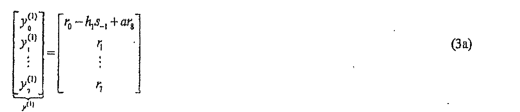

with the CP restoration being shown in equation (3a) and the channel matrix in equation (3b) being a circulant matrix. A general form for equations (3a) and (3b) is provided and discussedin "Efficient cyclic prefix reconstruction for coded OFDM systems," C. Park and G. Im, IEEE Communications Letters, vol. 8, no. 5, May 2004, pp.274-276. With a circulant matrix, time domain information can be cast to the frequency domain and the matrix inverted in a simple fashion. For subsequent iterations, k = 2, 3, ..., the symbol estimates


- In equations (3) and (4) the channel matrix from equation (1) has been manipulated into circulant form and can be factored as F -1 CF where F is a DFT (of FFT) matrix/operation, and C (the channel matrix in equation (4b)) is a circulant matrix to result in the diagonalized system in equation (6) below. The
CP restorer 72 calculates the values of y using equations (3a) and (4a), using estimates of the channel coefficients h from thechannel estimator 84 and hard symbol estimates from a previous iteration from theMAP detector 80, and outputs the y values to theFFT module 74. For the first iteration, the channel coefficients h are set to default values, e.g., zero. - The
FFT module 74 takes an FFT of the CP restored data to yield
where F represents the FFT operation. The frequency domain points
power spectrum plot 60 inFIG. 4 . TheFFT module 74 outputs the frequency domain points
MMSE estimator 76. With the FFT applied, the frequency domain model becomes:
where the u matrix is the Fourier transform of the w, noise, matrix, the x matrix data points are the received data in the frequency domain, the H matrix is the channel matrix in the frequency domain (provided by the channel estimator 84), and the t matrix is the Fourier transform of the symbol matrix (t=Fs) (i.e., the symbols in the frequency domain) and the data points in the t matrix are called the virtual sub-carriers, in reference to the sub-carriers in an OFDM (Orthogonal Frequency Division Multiplexing) system. Application of the principles of theFDTE 46 allow equation (1) to be rewritten as equation (6), which simplifies the matrix to be inverted and thus facilitates determination of the received symbols. For VSB modulations, the virtual sub-carriers are conjugate symmetric about half the symbol rate because the s values in the symbol matrix are real valued. Thus,
- Applying equation (7) to the system model of equation (6), the system model may be rewritten as:
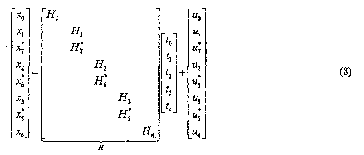
where, for simplicity, the indication of the iteration number (k) has been omitted. Thus, applying the symmetrical properties of VSB data, the number of frequency domain symbol values to be determined has reduced from eight, in this example, to five. Further, as seen from equation (8), all of the N received data points are used in determining the reduced set of symbols (i.e., here x 0 through x 8 are used to determine t 0 through t 4). For each virtual sub-carrier
equalizer 46 uses in-band data and channel estimates, i.e.

system 10 thus exploits the symmetry to efficiently recover the transmitted symbols at thereceiver 14. An advantage of this method can be seen in Equation (8), where more equations than unknown variables are being used to estimate the virtual sub-carriers. - The
MMSE module 76 recovers the values for t, which are the frequency domain symbols. TheMMSE module 76 applies a minimum mean squared error algorithm to recover estimated values for the t data points, The MMSE algorithm applied by theMMSE module 76 reduces error between true virtual sub-carriers and estimated virtual sub-carriers. The number of iterations performed by theMMSE module 76 can be limited in a variety of ways. For example, a variance determined by thestatistics computer 82 may be monitored and iterations performed until the variance reduces to within a desired tolerance (e.g., is smaller than a desired threshold), or a maximum number of allowable iterations is performed. Alternatively, theMMSE module 76 may perform a fixed number of iterations no matter what the value of the variance (or any other factor) is. To estimate the virtual sub-carrier values for iterations after the first iteration, theMMSE module 76 uses the expected/estimated virtual sub-carrier values, and variances of these estimated values, determined by thestatistics computer 82 in the immediately-prior iteration. In particular, theMMSE module 76 calculates the estimated virtual sub-carrier according to:
wheret (k-1) and
statistics computer 80 from the previous iteration.

t (k-1) is the frequency domain mean (average) of the possible values of a particular symbol. The variance averages the squared difference between the estimated virtual sub-carriers t̅ (k-1) and the expected valuet (k-1), thus providing a measure of confidence in the estimates, The expected value and the variance from the previous iteration may improve the estimation of the virtual sub-carrler, but need not be used (with theMAP detector 80 and thestatistics computer 82 also not being used and thus not part of the equalizer). For the first iteration, the variance and the expected value of each symbol can be set to respective default values, e.g., unity and zero, although the default values need not be zero and need not be the same for the expected value and variance, or the same for each symbol expected value. - Some mathematical manipulations can be used to restructure equation (9) to provide insight into its use. To further illustrate the MMSE estimation over each iteration k, define


The first component (before the plus sign) of the MMSE estimate in equation (9a) is approximately equal to the virtual sub-carrier estimatest (k-1) using the a priori information from the statistics computer 82 (described below) times the degree of confidence in that estimate according to the factor


t (0) = 0, and therefore t̅ (1) = HH (HHH + σ2 I)-1 x (1). As iterations progress, assuming the variance approaches zero, i.e.,
t (k-1) → t. - While equation (8) provides a specific example, for N = 8, of the relationship of the received data, x, the channel model H, the transmitted data t, and the noise/interference u, a general form for this relationship is given by:

Using this form, each virtual sub-carrier is given by
and
where equations (11) and (12) provide the generic form of equation (9) for the respective values of i shown. - The
FFT module 78 receives the frequency domain symbol estimates
MMSE estimator 76 and converts them into the time domain. TheFFT module 78 takes the inverse FFT of the MMSE virtual sub-carriers, while using the conjugate symmetric property of equation (7) to produce soft symbol estimates according to
- In equation (13), the conjugate-symmetric nature of the information being used is exploited to recover the transmitted symbols

FFT module 78 outputs the soft symbol stream of the last iteration, k, to the channel decoder 48 (FIG. 3 ), and to theMAP detector 80. - Referring also to
FIG. 6 , the MAP (maximum a posteriori)detector 80 includes aconditional distribution calculator 110 and aBCJR decoder 112. TheMAP detector 80 receives the soft symbol estimates from theFFT module 78 and converts these into hard symbol estimates
MAP detector 80 increases, possibly maximizes, the probability that a particular symbol sn has been transmitted given the soft symbol information from thesymbol estimator 70. This probability is referred to as the a posteriori probability
MAP detector 80 derives the a posteriori probability from a soft estimate distribution function conditioned on each possible symbol, i.e,
conditional distribution calculator 110 evaluates soft estimate conditional distributions
MAP detector 80 calculates hard symbol estimates according to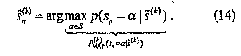
TheMAP detector 80 outputs the hard estimates to theCP restorer 72 and to thechannel estimator 84. - The
BCJR decoder 112 performs the MAP detection, taking as inputs the conditional distribution
- The
MAP detector 80 uses the conditional distributions evaluated at the sort symbol estimates and at each possible transmitted symbol value α The conditional distribution maybe approximated by
where the mean µ n,α and variance

MAP detector 80, in particular theBCJR decoder 112, sends the maximum a posteriori probabilities to thestatistics computer 82. - The
statistics computer 82 uses the conditional probabilities from theMAP detector 80 to derive the expected value and variance statistics of the virtual sub-carriers. Thestatistics computer 82 computes the expected value and variance according to

where s is the source constellation (i.e., s = {±1, ±3, ±5, ±7} for 8-VSB). Thestatistics computer 82 transforms these parameters to the frequency domain by taking the FFT of equations (16) and (17) to obtain corresponding quantities for the virtual sub-carriers according to

- Preferably, however, the
statistics computer 82 determines the average virtual sub-carrier variance according to
That simplifies computations, - The
channel estimator 84 uses the hard symbol estimates received from theMAP detector 80 to estimate the channel coefficients for use by theMMSE estimator module 78. Although channel estimation may be performed in other ways, here thechannel estimator 84 performs a cross-correlation of the hard symbol estimates from theMAP detector 80 with the received data such that if the hard symbol estimates are correct, i.e., ŝn = sn , then channel impulse response estimates are given by averaging according to
Assuming an iid (independent and identically distributed) system, unbiased channel impulse response estimates are given by ĥl = hi because
rn = h 0 sn + h 1 s n-1 + ... + hMsn-M + wn . Preferably, thechannel estimator 84 implements the averaging in equation (21) with a leaky integration according to
- The
channel estimator 84 preferably updates the channel impulse response estimates after each iteration k of theequalizer 46 as more accurate hard symbol estimates may improve the channel impulse response estimates. Thechannel estimator 84 further converts the time-dornain impulse response estimates to the frequency domain using an N-point FFT, with a length of the channel estimate being less than or equal to N coefficients. The resulting channel coefficients are provided to theMMSE module 78 for use as described above. Further detail of channel estimation implemented by thechannel estimator 84 is described in "Performance analysis of Godard-based blind channel identification," P. Schniter, R.A. Casas, A. Touzni, C.R. Johnson, Jr., IEEE Transactions on Signal Processing, September 1999. - Other embodiments are within the scope and spirit of the invention. For example, due to the nature of adverse fractions described above can be implemented using software, hardware, firmware, hardwiring, or combinations of any of these. Features implementing functions may also be physically located at various positions, including being distributed such that portions of functions are implemented at different physical locations.
- Further reductions in calculation complexity may also be implemented. For example, referring to
FIG. 4 and equations (8) and (12), estimation complexity may be reduced by setting (e.g., to zero) out-of-band data
- Further, white the description above refers to the invention, the description may include more than one invention.
Claims (20)
- In a digital communications receiver configured to receive, via a communications channel, a received first signal representing a sequence of symbols, each symbol being encoded to be representative of a plurality of data bits, a method of processing the received signal, the method comprising:adjusting a magnitude, filtering, and applying cyclic prefix restoration, to the received signal to produce a second signal;converting the second signal from time domain to frequency domain to produce a frequency domain signal; anddetermining a first quantity of values representing a first portion of the symbols by evaluating a relationship of channel values representing characteristics of the communications channel and a second quantity of values representing a portion of the frequency domain signal, the first quantity being smaller than the second quantity.
- The method of claim 1 wherein the determining further comprises using conjugates of some of the first quantity of values to determine a third quantity of values representing a second portion of the symbols, the second quantity equaling the first quantity plus the third quantity.
- The method of claim 2 wherein the first and second portions of the symbols are disposed on opposite sides of half of a rate for the received signal.
- The method of claim 2 further comprising applying MAP detection to values related to the third quantity of symbol values.
- The method of claim 1 wherein the determining further comprises iterating each of the first quantity of values using, for a respective one of the first quantity of values:information of a previous iteration value; anda variance associated with the previous iteration value.
- The method of claim 5 wherein using the information of a previous iteration value comprises using an expected value of a symbol.
- The method of claim 5 further comprising determining the variance and the confidence using probabilities that an estimated value of the first quantity of values is correct.
- A digital communications receiver, comprising:an input configured to receive, via a communications channel, a received first signal representing a sequence of symbols, each symbol being encoded to be representative of a plurality of data bits;a processor configured to adjust a magnitude and filter the received signal; andan equalizer configured to apply a cyclic prefix restoration to the adjusted and filtered signal, producing a second signal, to convert the second signal from time domain to frequency domain to produce a frequency domain signal, and to determine a first quantity of values representing a first portion of the symbols by evaluating a relationship of channel values representing characteristics of the communications channel and a second quantity of values representing a portion of the frequency domain signal, the first quantity being smaller than the second quantity.
- The digital communications receiver of claim 8 wherein the equalizer is further configured to use conjugates of some of the first quantity of values to determine a third quantity of values representing a second portion of the symbols, the second quantity equaling the first quantity plus the third quantity.
- The digital communications receiver of claim 9 wherein the first and second portions of the symbols are disposed on opposite sides of half of a sampling rate for the received signal.
- The digital communications receiver of claim 9, further comprising a MAP detector to apply MAP detection to values related to the third quantity of symbol values.
- The digital communications receiver of claim 8 wherein the equalizer further comprises:a cyclic prefix (CP) restorer, wherein the CP restorer applies the cyclic prefix restoration to the adjusted and filtered signal; anda fast fourier transform (FFT) device for producing the frequency domain signal.
- The digital communications receiver of claim 8 wherein the equalizer performs the determining by iterating each of the first quantity of values using, for a respective one of the first quantity of values:information of a previous iteration value; anda variance associated with the previous iteration value.
- The digital communications receiver of claim 13 wherein the equalizer uses an expected value of a symbol for the using of the information of a previous iteration value.
- The digital communications receiver of claim 13 wherein the equalizer is further configured to determine the variance and the confidence using probabilities that an estimated value of the first quantity of values is correct.
- The digital communications receiver of claim 8 wherein the equalizer is further configured to determine the characteristics of the channel using estimates of values of the first quantity of values.
- A digital communications receiver, comprising:an input configured to receive, via a communications channel, a received first signal representing a sequence of symbols, each symbol being encoded to be representative of a plurality of data bits;a processor configured to adjust a magnitude and filter the received signal; andan equalizer configured to apply a cyclic prefix restoration to the adjusted and filtered signal, producing a second signal, to convert the second signal from time domain to frequency domain to produce a frequency domain signal, and to determine a first quantity of values representing a first portion of the symbols by evaluating a relationship of channel values representing characteristics of the communications channel and a second quantity of values representing a portion of the frequency domain signal, the first quantity being smaller than the second quantity, the equalizer comprising:a cyclic prefix (CP) restorer for applying the cyclic prefix restoration to the adjusted and filtered signal;a fast fourier transform (FFT) device for producing the frequency domain signal;a minimum mean squared error (MMSE) device for estimating frequency domain virtual sub-carriers; andan estimator for using conjugates of some of the first quantity of values to determine a third quantity of values representing a second portion of the symbols, the second quantity equaling the first quantity plus the third quantity and wherein the first and second portions of the symbols are disposed on opposite sides of half of a sampling rate for the received signal.
- The digital communications receiver of claim 17, further comprising a MAP detector to apply MAP detection to values related to the third quantity of symbol values.
- An integrated circuit chip (IC) for receiving and processing a VSB signal, comprising:input circuitry configured to receive, via a communications channel, a received first signal representing a sequence of symbols, each symbol being encoded to be representative of a plurality of data bits;circuitry configured to adjust a magnitude and filter the received signal; andcircuitry configured to apply a cyclic prefix restoration to the adjusted and filtered signal, producing a second signal, to convert the second signal from time domain to frequency domain to produce a frequency domain signal, and to determine a first quantity of values representing a first portion of the symbols by evaluating a relationship of channel values representing characteristics of the communications channel and a second quantity of values representing a portion of the frequency domain signal, the first quantity being smaller than the second quantity.
- The IC of claim 19, further comprising circuitry configured to use conjugates of some of the first quantity of values to determine a third quantity of values representing a second portion of the symbols, the second quantity equaling the first quantity plus the third quantity and wherein the first and second portions of the symbols are disposed on opposite sides of half of a sampling rate for the received signal.
Applications Claiming Priority (3)
| Application Number | Priority Date | Filing Date | Title |
|---|---|---|---|
| US11/347,747 US7551679B2 (en) | 2006-02-03 | 2006-02-03 | Symmetrical data signal processing |
| EP07705538.2A EP1985081B1 (en) | 2006-02-03 | 2007-02-02 | Digital communications receiver |
| PCT/IB2007/000266 WO2007088481A2 (en) | 2006-02-03 | 2007-02-02 | Digital communications receiver |
Related Parent Applications (3)
| Application Number | Title | Priority Date | Filing Date |
|---|---|---|---|
| EP07705538.2 Division | 2007-02-02 | ||
| EP07705538.2A Division-Into EP1985081B1 (en) | 2006-02-03 | 2007-02-02 | Digital communications receiver |
| EP07705538.2A Division EP1985081B1 (en) | 2006-02-03 | 2007-02-02 | Digital communications receiver |
Publications (2)
| Publication Number | Publication Date |
|---|---|
| EP2611088A1 true EP2611088A1 (en) | 2013-07-03 |
| EP2611088B1 EP2611088B1 (en) | 2020-08-05 |
Family
ID=38327759
Family Applications (2)
| Application Number | Title | Priority Date | Filing Date |
|---|---|---|---|
| EP13161694.8A Active EP2611088B1 (en) | 2006-02-03 | 2007-02-02 | Digital communications receiver |
| EP07705538.2A Active EP1985081B1 (en) | 2006-02-03 | 2007-02-02 | Digital communications receiver |
Family Applications After (1)
| Application Number | Title | Priority Date | Filing Date |
|---|---|---|---|
| EP07705538.2A Active EP1985081B1 (en) | 2006-02-03 | 2007-02-02 | Digital communications receiver |
Country Status (3)
| Country | Link |
|---|---|
| US (3) | US7551679B2 (en) |
| EP (2) | EP2611088B1 (en) |
| WO (1) | WO2007088481A2 (en) |
Families Citing this family (22)
| Publication number | Priority date | Publication date | Assignee | Title |
|---|---|---|---|---|
| KR101199374B1 (en) | 2005-12-20 | 2012-11-09 | 엘지전자 주식회사 | Digital broadcasting system and processing method |
| US7627064B2 (en) * | 2006-06-30 | 2009-12-01 | Intel Corporation | System and method for enhanced symbol generation |
| US8345791B2 (en) * | 2006-07-12 | 2013-01-01 | France Telecom | Methods for transmitting and receiving a multicarrier signal comprising isolated pilots, corresponding devices and computer program products |
| SG141259A1 (en) * | 2006-09-12 | 2008-04-28 | Oki Techno Ct Singapore Pte | Apparatus and method for receiving digital video signals |
| US8938040B2 (en) * | 2006-10-05 | 2015-01-20 | Cohda Wireless Pty. Ltd. | Improving receiver performance in a communication network |
| KR101204394B1 (en) * | 2006-10-16 | 2012-11-26 | 포항공과대학교 산학협력단 | Transmitter, receiver for supporting space time block code scheme in single carrier system based on unique word and method thereof |
| CN101325569B (en) * | 2007-06-15 | 2013-09-04 | 安捷伦科技有限公司 | Robust channel evaluation for communication system |
| US20100093301A1 (en) * | 2008-10-14 | 2010-04-15 | Electronics And Telecommunications Research Institute | Heterodyne receiver using analog discrete-time signal processing and signal receiving method thereof |
| US8750089B2 (en) * | 2010-01-05 | 2014-06-10 | Broadcom Corporation | Method and system for iterative discrete fourier transform (DFT) based channel estimation using minimum mean square error (MMSE) techniques |
| US20120127870A1 (en) * | 2010-11-23 | 2012-05-24 | Wanlun Zhao | Method and Apparatus for Enabling an Enhanced Frequency Domain Equalizer |
| GB2487909B8 (en) | 2011-02-04 | 2015-01-21 | Sca Ipla Holdings Inc | Telecommunications method and system |
| EP2692103A1 (en) | 2011-03-30 | 2014-02-05 | Intel Corporation | Frequency domain equalization for wireless communication |
| WO2013010247A1 (en) * | 2011-07-21 | 2013-01-24 | Research In Motion Limited | Dynamic cyclic prefix mode for uplink radio resource management |
| WO2013100781A1 (en) | 2011-12-29 | 2013-07-04 | Intel Corporation | Frequency-domain turbo equalization, including multi-mode adaptive linear equalization, adaptive decision-directed channel estimation, adaptive noise variance estimation, and dynamic iteration control |
| US9401826B2 (en) * | 2012-02-17 | 2016-07-26 | Sony Corporation | Signal processing unit employing a blind channel estimation algorithm and method of operating a receiver apparatus |
| US9614560B2 (en) | 2012-03-30 | 2017-04-04 | Intel Corporation | Receiver with improved noise variance estimation |
| WO2013172729A1 (en) | 2012-05-15 | 2013-11-21 | Intel Corporation | Receiver with doppler tolerant equalization |
| US9786291B2 (en) * | 2014-06-18 | 2017-10-10 | Google Technology Holdings LLC | Communicating information between devices using ultra high frequency audio |
| US9787356B2 (en) * | 2015-09-22 | 2017-10-10 | Nxp Usa, Inc. | System and method for large dimension equalization using small dimension equalizers |
| US9667455B1 (en) | 2016-03-23 | 2017-05-30 | Nxp Usa, Inc. | System and method for large dimension equalization using small dimension equalizers and bypassed equalizers |
| US11683203B2 (en) | 2018-05-04 | 2023-06-20 | Marvell Asia Pte, Ltd. | Methods and apparatus for providing a demapping system with phase compensation to demap uplink transmissions |
| US12289185B1 (en) * | 2018-05-04 | 2025-04-29 | Marvell Asia Pte Ltd | Method and apparatus for providing an equalizer that achieves a given precision for non-invertible matrices |
Family Cites Families (18)
| Publication number | Priority date | Publication date | Assignee | Title |
|---|---|---|---|---|
| US6680971B1 (en) * | 1998-05-18 | 2004-01-20 | Sarnoff Corporation | Passband equalizer for a vestigial sideband signal receiver |
| US6842495B1 (en) * | 1998-11-03 | 2005-01-11 | Broadcom Corporation | Dual mode QAM/VSB receiver |
| KR100314113B1 (en) * | 1999-08-25 | 2001-11-15 | 구자홍 | matched filter and filtering method, apparatus and method for receiving plural digital broadcast using digital filter |
| US6449246B1 (en) * | 1999-09-15 | 2002-09-10 | Telcordia Technologies, Inc. | Multicarrier personal access communication system |
| AU2280300A (en) * | 1999-11-27 | 2001-06-12 | Deutsche Telekom Ag | Method for co-channel interference cancelation in a multicarrier communication system |
| US6975689B1 (en) * | 2000-03-30 | 2005-12-13 | Mcdonald James Douglas | Digital modulation signal receiver with adaptive channel equalization employing discrete fourier transforms |
| US7248841B2 (en) * | 2000-06-13 | 2007-07-24 | Agee Brian G | Method and apparatus for optimization of wireless multipoint electromagnetic communication networks |
| KR100400752B1 (en) * | 2001-02-07 | 2003-10-08 | 엘지전자 주식회사 | Apparatus for VSB demodulating in digital TV receiver |
| US7054359B2 (en) * | 2001-06-05 | 2006-05-30 | Koninklijke Philips Electronics N.V. | VSV-MOE pre-equalizer for 8-VSB DTV |
| KR100442882B1 (en) * | 2002-07-26 | 2004-08-02 | 삼성전자주식회사 | Methods for station recognition and link establishment in Home-network |
| US7359450B1 (en) * | 2003-04-04 | 2008-04-15 | Nucomm, Inc. | Digital transmission of broadcast signals, including HDTV signals, over a microwave link |
| US20050090213A1 (en) * | 2003-10-23 | 2005-04-28 | Heng Chun H. | Tuner and demodulator for analog cable television |
| KR100575982B1 (en) * | 2003-11-05 | 2006-05-02 | 삼성전자주식회사 | Apparatus and Method for Eliminating Interference Signals in Orthogonal Frequency Division Multiplexing System Using Multiple Antennas |
| JP3802031B2 (en) * | 2004-02-16 | 2006-07-26 | パイオニア株式会社 | Receiving apparatus and receiving method |
| US20060045169A1 (en) * | 2004-08-27 | 2006-03-02 | Qualcomm Incorporated | Coded-bit scrambling for multi-stream communication in a mimo channel |
| KR20060059221A (en) * | 2004-11-26 | 2006-06-01 | 삼성전자주식회사 | Apparatus and method for reducing peak-to-average power ratio in multicarrier communication systems |
| KR100749447B1 (en) * | 2004-12-21 | 2007-08-14 | 한국전자통신연구원 | method and apparatus for estimating timing error and frequency offset of HPI system |
| US7609773B2 (en) * | 2005-04-18 | 2009-10-27 | Qualcomm Incorporated | Method of determining the location of the FFT window and the delay spread for the platinum broadcast channel estimator |
-
2006
- 2006-02-03 US US11/347,747 patent/US7551679B2/en active Active
-
2007
- 2007-02-02 WO PCT/IB2007/000266 patent/WO2007088481A2/en not_active Ceased
- 2007-02-02 EP EP13161694.8A patent/EP2611088B1/en active Active
- 2007-02-02 EP EP07705538.2A patent/EP1985081B1/en active Active
-
2009
- 2009-05-13 US US12/465,322 patent/US8054900B2/en active Active
-
2011
- 2011-11-07 US US13/290,256 patent/US8498352B2/en not_active Expired - Fee Related
Non-Patent Citations (9)
| Title |
|---|
| BERTRAND MUQUET ET AL: "Cyclic Prefixing or Zero Padding for Wireless Multicarrier Transmissions?", IEEE TRANSACTIONS ON COMMUNICATIONS, IEEE SERVICE CENTER, PISCATAWAY, NJ. USA, vol. 50, no. 12, December 2002 (2002-12-01), XP011071075, ISSN: 0090-6778 * |
| C. PARK; G. IM: "Efficient cyclic prefix reconstruction for coded OFDM systems", IEEE COMMUNICATIONS LETTERS, vol. 8, no. 5, May 2004 (2004-05-01), pages 274 - 276, XP001198344, DOI: doi:10.1109/LCOMM.2004.827439 |
| EORY F: "Comparison of adaptive equalization methods for the ATSC and DVB-T digital television broadcast systems", PROCEEDINGS OF THE 2000 THIRD IEEE INTERNATIONAL CONFERENCE ONDEVICES, CIRCUITS AND SYSTEMS, 2000. CARACAS MARCH 15-17, 2000, PISCATAWAY, NJ, USA,IEEE, 15 March 2000 (2000-03-15), pages 487 - 493, XP010512107, ISBN: 0-7803-5766-3 * |
| GHOGHO M ET AL: "Blind frequency-offset estimator for OFDM systems transmitting constant-modulus symbols", IEEE COMMUNICATIONS LETTERS, IEEE SERVICE CENTER, PISCATAWAY, NJ, US, vol. 6, no. 8, August 2002 (2002-08-01), pages 343 - 345, XP011429941, ISSN: 1089-7798, DOI: 10.1109/LCOMM.2002.802040 * |
| KELLER T ET AL: "Adaptive multicarrier modulation: a convenient framework for time-frequency processing in wireless communications", PROCEEDINGS OF THE IEEE, IEEE. NEW YORK, US, vol. 88, no. 5, May 2000 (2000-05-01), pages 611 - 640, XP011450711, ISSN: 0018-9219, DOI: 10.1109/5.849157 * |
| P, SCHNITER; H. LIN: "Iterative Frequency-Domain Equalization for Single-Carrier Systems in Doubly-Dispersive Channels", PROC. ASILOMAR CONF ON SIGNALS, SYSTEMS, AND COMPUTERS, November 2004 (2004-11-01), pages 667 - 671, XP010779881, DOI: doi:10.1109/ACSSC.2004.1399218 |
| P. SCHNITER; R.A. CASAS; A. TOUZNI; C.R. JOHNSON, JR.: "Performance analysis of Godard-based blind channel identification", IEEE TRANSACTIONS ON SIGNAL PROCESSING, September 1999 (1999-09-01) |
| WEN-RONG WU ET AL: "ISI Mitigation and Channel Tracking in MIMO-OFDM Systems", PROCEEDINGS OF 2005 INTERNATIONAL SYMPOSIUM ON INTELLIGENT SIGNAL PROCESSING AND COMMUNICATION SYSTEMS, 2005. ISPACS 2005 HONG KONG 13-16 DEC. 2005, PISCATAWAY, NJ, USA,IEEE, 13 December 2005 (2005-12-13), pages 101 - 104, XP010894546, ISBN: 0-7803-9266-3 * |
| WON H-C ET AL: "ITERATIVE CYCLIC PREFIX RECONSTRUCTION AND CHANNEL ESTIMATION FOR A STBC OFDM SYSTEM", IEEE COMMUNICATIONS LETTERS, IEEE SERVICE CENTER, PISCATAWAY, NJ, US, vol. 9, no. 4, April 2005 (2005-04-01), pages 307 - 309, XP001226180, ISSN: 1089-7798 * |
Also Published As
| Publication number | Publication date |
|---|---|
| WO2007088481A3 (en) | 2007-11-01 |
| US8498352B2 (en) | 2013-07-30 |
| EP1985081B1 (en) | 2020-05-20 |
| US8054900B2 (en) | 2011-11-08 |
| EP2611088B1 (en) | 2020-08-05 |
| US20120051412A1 (en) | 2012-03-01 |
| EP1985081A2 (en) | 2008-10-29 |
| US7551679B2 (en) | 2009-06-23 |
| US20070183517A1 (en) | 2007-08-09 |
| WO2007088481A2 (en) | 2007-08-09 |
| US20090262864A1 (en) | 2009-10-22 |
Similar Documents
| Publication | Publication Date | Title |
|---|---|---|
| EP1985081B1 (en) | Digital communications receiver | |
| US8325790B2 (en) | Equalization for OFDM communication | |
| US7027500B1 (en) | Linear prediction based initialization of a single-axis blind equalizer for VSB signals | |
| CN101341677B (en) | Inter-carrier interference removal device and reception device using the same | |
| US8837616B2 (en) | Equalization of a distributed pilot OFDM signal | |
| US7920462B2 (en) | Amplitude attenuation estimation and recovery systems for OFDM signal used in communication systems | |
| US7616685B2 (en) | Method for channel tracking in an LMS adaptive equalizer for 8VSB | |
| CN101682457B (en) | Receiving device, receiving method, integrated circuit, digital television receiver | |
| US20080304589A1 (en) | Wireless receiver, method for controlling the wireless receiver, program for controlling the wireless receiver, and semiconductor integrated circuit | |
| WO1999043114A1 (en) | Method and apparatus for signal reception, and medium | |
| US20190245569A1 (en) | Method for compensation of phase noise effect on data transmission in radio channel | |
| US20030185326A1 (en) | Frequency drift and phase error compensation in a VOFDM receiver | |
| EP1895780A2 (en) | Frame synchronization for a video receiver | |
| JP2008532354A (en) | Wireless communication apparatus and associated method for providing improved block equalization | |
| US20080063040A1 (en) | Equalizer demodulating a signal including sp symbols and an equalization method therefor | |
| EP1195960A2 (en) | Demapping in a multicarrier receiver | |
| CN101138150A (en) | Wireless communication device and related method for performing block equalization based on previous, current and/or future autocorrelation matrix estimation | |
| US7349469B1 (en) | DC offset correction for constant modulus equalization | |
| US20100074346A1 (en) | Channel estimation in ofdm receivers | |
| EP2884682A1 (en) | Receiver, method for estimating frequency response of transmission path by receiver | |
| US7295144B1 (en) | Quantizer responsive to noise level for a wireless communications system | |
| TWI452901B (en) | Method and system for tracking phase in a receiver for 8vsb | |
| JP2008263571A (en) | Local oscillation phase noise suppression transceiver | |
| US8605827B2 (en) | Timing errors | |
| KR100231782B1 (en) | The equalising method combining the carrier phase recovering |
Legal Events
| Date | Code | Title | Description |
|---|---|---|---|
| PUAI | Public reference made under article 153(3) epc to a published international application that has entered the european phase |
Free format text: ORIGINAL CODE: 0009012 |
|
| AC | Divisional application: reference to earlier application |
Ref document number: 1985081 Country of ref document: EP Kind code of ref document: P |
|
| AK | Designated contracting states |
Kind code of ref document: A1 Designated state(s): DE FR GB |
|
| RIN1 | Information on inventor provided before grant (corrected) |
Inventor name: LIU, HONG Inventor name: CASAS, RAUL, A. Inventor name: FU, HAOSONG |
|
| 17P | Request for examination filed |
Effective date: 20131231 |
|
| RBV | Designated contracting states (corrected) |
Designated state(s): DE FR GB |
|
| 17Q | First examination report despatched |
Effective date: 20150415 |
|
| STAA | Information on the status of an ep patent application or granted ep patent |
Free format text: STATUS: EXAMINATION IS IN PROGRESS |
|
| GRAP | Despatch of communication of intention to grant a patent |
Free format text: ORIGINAL CODE: EPIDOSNIGR1 |
|
| STAA | Information on the status of an ep patent application or granted ep patent |
Free format text: STATUS: GRANT OF PATENT IS INTENDED |
|
| INTG | Intention to grant announced |
Effective date: 20191127 |
|
| GRAS | Grant fee paid |
Free format text: ORIGINAL CODE: EPIDOSNIGR3 |
|
| GRAA | (expected) grant |
Free format text: ORIGINAL CODE: 0009210 |
|
| STAA | Information on the status of an ep patent application or granted ep patent |
Free format text: STATUS: THE PATENT HAS BEEN GRANTED |
|
| AC | Divisional application: reference to earlier application |
Ref document number: 1985081 Country of ref document: EP Kind code of ref document: P |
|
| AK | Designated contracting states |
Kind code of ref document: B1 Designated state(s): DE FR GB |
|
| REG | Reference to a national code |
Ref country code: GB Ref legal event code: FG4D |
|
| REG | Reference to a national code |
Ref country code: DE Ref legal event code: R096 Ref document number: 602007060524 Country of ref document: DE |
|
| REG | Reference to a national code |
Ref country code: DE Ref legal event code: R097 Ref document number: 602007060524 Country of ref document: DE |
|
| PLBE | No opposition filed within time limit |
Free format text: ORIGINAL CODE: 0009261 |
|
| STAA | Information on the status of an ep patent application or granted ep patent |
Free format text: STATUS: NO OPPOSITION FILED WITHIN TIME LIMIT |
|
| 26N | No opposition filed |
Effective date: 20210507 |
|
| PG25 | Lapsed in a contracting state [announced via postgrant information from national office to epo] |
Ref country code: FR Free format text: LAPSE BECAUSE OF NON-PAYMENT OF DUE FEES Effective date: 20210228 |
|
| P01 | Opt-out of the competence of the unified patent court (upc) registered |
Effective date: 20230530 |
|
| PGFP | Annual fee paid to national office [announced via postgrant information from national office to epo] |
Ref country code: DE Payment date: 20250128 Year of fee payment: 19 |
|
| PGFP | Annual fee paid to national office [announced via postgrant information from national office to epo] |
Ref country code: GB Payment date: 20250210 Year of fee payment: 19 |