EP2607282A1 - Safety device for a lift with multiple cabins - Google Patents
Safety device for a lift with multiple cabins Download PDFInfo
- Publication number
- EP2607282A1 EP2607282A1 EP11195470.7A EP11195470A EP2607282A1 EP 2607282 A1 EP2607282 A1 EP 2607282A1 EP 11195470 A EP11195470 A EP 11195470A EP 2607282 A1 EP2607282 A1 EP 2607282A1
- Authority
- EP
- European Patent Office
- Prior art keywords
- safety device
- cabin
- distance
- cabins
- elevator
- Prior art date
- Legal status (The legal status is an assumption and is not a legal conclusion. Google has not performed a legal analysis and makes no representation as to the accuracy of the status listed.)
- Withdrawn
Links
Images
Classifications
-
- B—PERFORMING OPERATIONS; TRANSPORTING
- B66—HOISTING; LIFTING; HAULING
- B66B—ELEVATORS; ESCALATORS OR MOVING WALKWAYS
- B66B5/00—Applications of checking, fault-correcting, or safety devices in elevators
- B66B5/0006—Monitoring devices or performance analysers
- B66B5/0018—Devices monitoring the operating condition of the elevator system
- B66B5/0031—Devices monitoring the operating condition of the elevator system for safety reasons
-
- B—PERFORMING OPERATIONS; TRANSPORTING
- B66—HOISTING; LIFTING; HAULING
- B66B—ELEVATORS; ESCALATORS OR MOVING WALKWAYS
- B66B1/00—Control systems of elevators in general
- B66B1/24—Control systems with regulation, i.e. with retroactive action, for influencing travelling speed, acceleration, or deceleration
- B66B1/28—Control systems with regulation, i.e. with retroactive action, for influencing travelling speed, acceleration, or deceleration electrical
- B66B1/30—Control systems with regulation, i.e. with retroactive action, for influencing travelling speed, acceleration, or deceleration electrical effective on driving gear, e.g. acting on power electronics, on inverter or rectifier controlled motor
-
- B—PERFORMING OPERATIONS; TRANSPORTING
- B66—HOISTING; LIFTING; HAULING
- B66B—ELEVATORS; ESCALATORS OR MOVING WALKWAYS
- B66B1/00—Control systems of elevators in general
- B66B1/24—Control systems with regulation, i.e. with retroactive action, for influencing travelling speed, acceleration, or deceleration
- B66B1/28—Control systems with regulation, i.e. with retroactive action, for influencing travelling speed, acceleration, or deceleration electrical
- B66B1/32—Control systems with regulation, i.e. with retroactive action, for influencing travelling speed, acceleration, or deceleration electrical effective on braking devices, e.g. acting on electrically controlled brakes
-
- B—PERFORMING OPERATIONS; TRANSPORTING
- B66—HOISTING; LIFTING; HAULING
- B66B—ELEVATORS; ESCALATORS OR MOVING WALKWAYS
- B66B5/00—Applications of checking, fault-correcting, or safety devices in elevators
- B66B5/02—Applications of checking, fault-correcting, or safety devices in elevators responsive to abnormal operating conditions
- B66B5/04—Applications of checking, fault-correcting, or safety devices in elevators responsive to abnormal operating conditions for detecting excessive speed
- B66B5/06—Applications of checking, fault-correcting, or safety devices in elevators responsive to abnormal operating conditions for detecting excessive speed electrical
Definitions
- the present invention relates to an elevator with two independently movable cabins and with a safety device for avoiding a collision between the two cabins according to the subject-matter of the independent claim.
- a safety device which takes into account the above-mentioned problem.
- This safety device prevents a collision between two cabins by the safety device monitors whether the cabs comply with a minimum safety distance. When falling below this safety distance, the safety device initiates an emergency stop. The safety device continues to monitor the distance between the two cabs when performing the emergency stop. If, despite the emergency stop, a further approach of the cabins takes place and a critical safety distance is undershot, the safety device initiates a catch braking.
- the elevator includes a first and a second cabin, which share a common
- Roadway are movable, a safety device with which the two cabins are monitored, and a shaft information system, which is connected to the safety device and with which the speed and position of the two cabins can be determined.
- a first braking action can be initiated when the two cars fall below a safe distance.
- the elevator is characterized in that a deceleration curve for the at least first cabin can be predetermined by means of the safety device when the first braking measure is initiated.
- a second braking measure can be introduced through the at least first cabin.
- the advantage of this elevator is that, after the first braking measure has been initiated, the safety device specifies a deceleration curve for the first car. As a result, the distance between the first car and the second car no longer needs to be monitored. During the deceleration, the safety device compares only the speed of the first car with the predetermined speed value of the deceleration curve per distance traveled. This simple value comparison places relatively low demands on the computing capacity of the safety device.
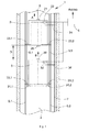
- the FIG. 1 shows an elevator 1 with at least two cabins 2, 3. Each of these cabins 2, 3 is substantially independently along a common roadway movable. in the As shown, the roadway is defined by a pair of car guide rails 5.1, 5.2 installed in a hoistway 4.
- the cabins 2, 3 are each suspended on a support means 8, 9.1, 9.2.
- the suspension ratio of 1: 1 shown here is a common suspension ratio in elevator construction.
- the skilled person is free to choose a deviating higher suspension ratio of 2: 1, 3: 1 or higher.
- the upper car 2 is suspended at a first suspension point 21 on a first support means 8.
- the suspension point 21 preferably lies centrally on the upper side of the upper car 2. From the first suspension point 21, the suspension element extends upwards into the upper region of the elevator shaft 4. There, the first suspension element 8 runs over a first traction sheave. By means of the traction sheave and optional first pulleys, the first support means 8 is again guided down to a first counterweight. The first counterweight is also suspended from the first support means 8 and balances the weight of the upper car 2.
- a lower cabin 3 is attached to second and third suspension points 31.1, 31.2 on a second suspension element, which comprises two second suspension element strands 9.1, 9.2.
- the lower cabin 3 is preferably suspended in its lower region on opposite sides on the second suspension element strands 9.1, 9.2.
- the suspension element strands 9.1, 9.2 extend laterally past the upper cabin 2 upwards into the upper region of the elevator shaft 4.
- the second suspension element strands 9.1, 9.2 run over second traction sheaves.
- the second suspension element strands 9.1, 9.2 are again guided downwards to a second counterweight.
- the second counterweight is finally also suspended from the second suspension element strands 9.1, 9.2 and balances the weight of the lower elevator car 3 from.
- the first and second traction sheaves are each driven by a first and second drive.
- the first and second drives transmitted by means of the respectively associated traction sheave drive torque to the first and second support means 8, 9.1, 9.2. Accordingly, the two cabins 2, 3 largely independent of each other by an associated drive movable. These are equipped with the first and second drives depending on an associated engine and depending on an associated drive brake.
- an elevator control 6 which controls the two drives of the cabins 2, 3.
- call input devices which are each arranged on a floor and connected to the elevator control 6, a passenger calls a car 2, 3 on a floor.
- these call input devices are designed as destination call input devices.
- a passenger In the operation of such a destination call input device, a passenger not only displays his location at a floor on which he waits for a car 2, 3, but also notifies the elevator controller 6 of his desired destination floor.
- the elevator control 6 assigns a suitable car 2, 3 to this call and moves the allocated car 2, 3 to the floor and finally to the destination floor.
- the elevator control 6 controls the motor and the drive brake of the allocated cabin 2, 3 associated drive.
- the elevator 1 has a shaft information system.
- This shaft information system comprises, for example, a code strip 7 with code marks and, per cabin 2, 3, a sensor 24, 34 for reading the code marks.
- the code strip 7 is mounted along the carriageway in the elevator shaft 4.
- the code marks preferably represent a unique, unmistakable position information.
- Speed information can be generated by means of an evaluation of the position information over time.
- the shaft information system thus provides at least information about its position and speed of the elevator control 6 and the safety device 22, 32 for each car 2, 3.
- the safety device 22, 32 evaluates the position information and / or speed information received from the sensors 24, 34. This also includes the calculation of a distance between the cars 2, 3 from their position information.
- the shaft information system has a distance sensor 25, which is arranged on the upper car 2.
- this distance sensor 25 the distance to the lower cabin 3 can be detected.
- the lower cabin 3 can be equipped with a distance sensor 36, with which a distance to the adjacent upper cabin 2 can be detected.
- the distance sensors 25, 36 are each connected to the safety device 22, 32.
- the safety device 22, 32 evaluates the distance information from the distance sensors 25, 36 incoming.
- a distance sensor 25, 36 is for example a laser distance measuring sensor or designed as Ultraschallabstandmesssensor
- the safety device 22, 32 check the incoming distance information of the respective distance sensors 25, 36 for equality. In this plausibility test, the safety device 22, 32 determines whether the distance sensors 25, 32 function reliably. If the distance information of the distance sensors 25, 36 does not match, the safety device 22, 32 takes appropriate measures to bring the elevator 1 into a safe state. For example, the safety device 22, 32 can immobilize the elevator 1, since a collision between the cars 2, 3 can no longer be ruled out if the distance information is incorrectly evaluated.
- the distance information of the distance sensors 25, 36 are also comparable in a plausibility test with the distance calculated by the shaft information system from the position information of the cars 2, 3.
- each cabin 2, 3 is associated with a decentralized operating safety device 22, 32 which is in each case in communication with the cabin brake 23.1, 23.2, 33.1, 33.2 associated with a car 2, 3 and the sensors 24, 34.
- the sensors 24, 34 transmit position and speed information to the safety device 22, 32.
- the car brakes 23.1, 23.2, 33.1, 33.2 can be controlled by the safety device 22, 32.
- the safety device 22, 32 communicates with the elevator control 6 and indirectly controls the first and second drive as well as its associated drive brakes and motors. Via the elevator control unit 6, a respective safety device 22, 32 also has information about the position and speed of the respective other car 3, 2.
- the safety device 22, 32 of a car 2, 3 is directly connected to the respective drive and their associated drive brakes and may possibly directly drive the drive or the drive brakes or motors.
- a central safety device can be used, which monitors both cabins 2, 3 and controls the drives and cabin brakes 23.1, 23.2, 33.1, 33.2.
- a direct exchange of information about the position and speed of each other cabin 2, 3 between the two safety devices 22, 32 is possible.
- FIG. 1 The example shown relates to a snapshot in which the upper car 2 drives ahead in a direction A and a lower car 3 follows in a same direction B of the upper car 2.
- the safety device 32 of the lower trailing cab 3 compares the current distance with a permissible safety distance D.
- the safety device 32 has at least one processor and a memory unit, wherein a program for comparing a current distance with the safety distance D is stored on the memory unit and Processor calls this program and makes the comparison.
- This program compares distance information provided by the hoistway information system with a safety distance D.
- This safety distance D is stored on the memory unit either as a fixed preset value or as another program enabling a speed-dependent calculation of the safety distance D.
- the permissible safety distance D represents a distance at which just a safe deceleration of the following lower cabin 3 is possible. If this permissible safety distance is exceeded, the safety device 32 initiates a first braking action in order to prevent a collision between the two cars 2 and 3. For this purpose, the safety device 32 controls the drive of the following lower cab 3 to decelerate the lower cab 3.
- the first braking measure is preferably carried out by actuation of a drive brake assigned to the drive. Alternatively or additionally, the first braking measure with a motor associated with the drive by applying a rotational movement of an associated traction sheave opposite torque can be performed.
- the safety device 32 When initiating the first braking measure, the safety device 32 gives the following lower cabin 3 a deceleration curve.
- this delay curve is stored permanently on the memory unit.
- the deceleration curve preferably depends on the nominal speed which a car 2, 3 reaches during normal operation of the elevator 1.
- the delay curve by means of another program, which is stored on the storage unit, speed-dependent calculable. To do this, the processor calls this program and performs the corresponding calculation.
- the safety device 22, 32 compares the braking distance traveled by the instantaneous speed of the following lower cabin 3 with the speed value predetermined by the deceleration curve. For this comparison, another program is stored on the memory unit, which the processor calls and executes. If this deceleration curve can not be maintained by means of the first braking action, i.e. if a speed associated with an achieved braking distance is exceeded, the safety device 32 initiates a second braking action.
- the safety device 32 controls the cabin brake 33.1, 33.2 assigned to the following lower cabin 3 to brake the lower cabin 3.
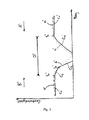
- the invention can be applied to opposite directions of travel of the cabins 2, 3, wherein the lower cabin 3 as in the Fig. 1 shown moves in a direction B and the upper cabin 2 in a direction opposite to the direction A on the lower cabin 3 moves.
- the safety distance D is doubled to 2 * D. If this safety distance falls below 2 * D, the safety device 22, 32 controls both drives or drive brakes or motors in order to initiate a first braking action. Both cabins 2, 3 are braked.
- the safety distance 2 * D is speed-dependent from the safety device 22, 32 can be fixed. The faster a car 2, 3 is moved, the greater the safety distance D can be determined.
- the safety device 22, 32 for each car 2, 3 before a deceleration curve. If one of the two cabins 2, 3 or even both cabins 2, 3 can not or can not comply with this deceleration curve or exceed or exceed a speed for a predetermined braking distance achieved, the safety device 22, 32 initiates a second braking action for the affected cabin 2 , 3 on.
- the safety device 22, 32 controls the cabin brake 23.1, 23.2, 33.1, 33.2 of the respective car 2, 3 in order to decelerate the car 2, 3.
- opposite directions of travel A, B of the two cabins 2, 3 so by means of the safety device 22, 32 for the first and for the second car 2, 3 depending on a first or possibly a second braking action can be introduced.
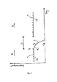
- Fig. 2 and 3 are two braking examples based on a path-speed curve of the two cabins 2, 3 shown.
- Fig. 2 shows a situation similar to that Fig. 1 equivalent.
- Both cabins 2, 3 are moved in the same direction of travel A, B.
- a first preceding car 2 is moved in the direction of travel A and a second following car 3 is moved in the direction of travel B.
- the following car 3 is moved before a time t1 at a speed c1, which is below the nominal speed n.
- the preceding car 2 on the other hand, is moved before a time t1 at a speed which is less than c1. This is the case, for example, after a stop on a floor when approaching the preceding car 2.
- the travel of the preceding car 2 before the time t1 is in the Fig. 2 not shown for clarity.
- the safety device 32 initiates a first braking action.
- the safety device 32 predefines a deceleration curve b.
- the speed of the following car 3 is above the predetermined deceleration curve b. This causes the safety device 32 for the following cabin 3 to initiate a second braking action.
- the following car 3 of the deceleration cam c3 is decelerated accordingly to standstill. During this two-stage braking process of the following car 3, the preceding car 2 can be moved on at the speed c1.
- the safety device 22, 32 each provide a deceleration curve b 'for both cabins 2, 3.
- the first and second car 2, 3 of the deceleration cam c2 ' are decelerated accordingly.
- the speed of the lower car 3 is above the predetermined deceleration curve b'.
- This causes the safety device 32 for the lower cabin 3 to initiate a second braking action.
- the lower cabin 3 is decelerated accordingly until the deceleration curve c3 'stops.
- the upper cabin 2 however, remains after initiation of the first braking measure until reaching standstill always below the predetermined deceleration curve b '.
- a second braking measure is not necessary for the upper cabin 2.
Landscapes
- Engineering & Computer Science (AREA)
- Automation & Control Theory (AREA)
- Elevator Control (AREA)
- Maintenance And Inspection Apparatuses For Elevators (AREA)
Abstract
Description
Die vorliegende Erfindung betrifft einen Aufzug mit zwei unabhängig verfahrbaren Kabinen und mit einer Sicherheitseinrichtung zum Vermeiden einer Kollision zwischen den beiden Kabinen gemäss dem Gegenstand des unabhängigen Anspruchs.The present invention relates to an elevator with two independently movable cabins and with a safety device for avoiding a collision between the two cabins according to the subject-matter of the independent claim.
Beim Betreiben von Aufzügen mit mindestens zwei Kabinen, die entlang einer gemeinsamen Fahrbahn verfahrbar sind, stellt sich stets die Problematik der Kollisionsvermeidung.When operating elevators with at least two cabins, which can be moved along a common roadway, there is always the problem of collision avoidance.
In der europäischen Patentschrift
Bei diesem zweistufigen Bremsverfahren in Abhängigkeit eines minimalen und eines kritischen Sicherheitsabstands, ist der Abstand der beiden Aufzugkabinen fortlaufend zu überwachen. Diese kontinuierliche Überwachung der Distanz stellt relativ hohe Anforderungen an die Rechenkapazität der Sicherheitseinrichtung.In this two-stage braking process as a function of a minimum and a critical safety distance, the distance between the two elevator cars is to be continuously monitored. This continuous monitoring of the distance places relatively high demands on the computing capacity of the safety device.
Dementsprechend ist es die Aufgabe der vorliegenden Erfindung einen Aufzug mit einer Sicherheitseinrichtung zu entwickeln, die eine Kollision zwischen den Kabinen einfach und zuverlässig verhindert.Accordingly, it is the object of the present invention to develop an elevator with a safety device that easily and reliably prevents a collision between the cars.
Die Aufgabe wird durch einen Aufzug gemäss dem Gegenstand des unabhängigen Anspruchs gelöst.The object is achieved by a lift according to the subject of the independent claim.
Der Aufzug umfasst eine erste und eine zweite Kabine, die entlang einer gemeinsamenThe elevator includes a first and a second cabin, which share a common
Fahrbahn verfahrbar sind, eine Sicherheitseinrichtung, mit der die beiden Kabinen überwachbar sind, und ein Schachtinformationssystem, das mit der Sicherheitseinrichtung verbunden ist und mit dem die Geschwindigkeit und Position der beiden Kabinen bestimmbar sind. Dabei ist mittels der Sicherheitseinrichtung für mindestens eine erste Kabine eine erste Bremsmassnahme einleitbar, wenn die beiden Kabinen einen Sicherheitsabstand unterschreiten. Der Aufzug zeichnet sich dadurch aus, dass mittels der Sicherheitseinrichtung beim Einleiten der ersten Bremsmassnahme eine Verzögerungskurve für die mindestens erste Kabine vorgebbar ist. Mittels der Sicherheitseinrichtung ist bei Überschreiten der Verzögerungskurve durch die mindestens erste Kabine eine zweite Bremsmassnahme einleitbar.Roadway are movable, a safety device with which the two cabins are monitored, and a shaft information system, which is connected to the safety device and with which the speed and position of the two cabins can be determined. In this case, by means of the safety device for at least one first cabin, a first braking action can be initiated when the two cars fall below a safe distance. The elevator is characterized in that a deceleration curve for the at least first cabin can be predetermined by means of the safety device when the first braking measure is initiated. By means of the safety device, when the deceleration curve is exceeded, a second braking measure can be introduced through the at least first cabin.
Der Vorteil dieses Aufzugs liegt darin, dass nach Einleiten der ersten Bremsmassnahme die Sicherheitseinrichtung eine Verzögerungskurve für die erste Kabine vorgibt. In der Folge muss der Abstand zwischen der ersten Kabine und der zweiten Kabine nicht mehr weiter überwacht werden. Die Sicherheitseinrichtung vergleicht während der Verzögerung lediglich die Geschwindigkeit der ersten Kabine mit dem vorgegebenen Geschwindigkeitswert der Verzögerungskurve pro zurückgelegten Bremsweg. Dieser einfache Wertvergleich stellt relativ geringe Anforderungen an die Rechenkapazität der Sicherheitseinrichtung.The advantage of this elevator is that, after the first braking measure has been initiated, the safety device specifies a deceleration curve for the first car. As a result, the distance between the first car and the second car no longer needs to be monitored. During the deceleration, the safety device compares only the speed of the first car with the predetermined speed value of the deceleration curve per distance traveled. This simple value comparison places relatively low demands on the computing capacity of the safety device.
Im Folgenden wird die Erfindung durch Ausführungsbeispiele und Figuren verdeutlicht und weiter beschrieben. Es zeigen:
-
Fig. 1 einen Aufzug mit einer Sicherheitseinrichtung zum Verhindern einer Kollision zwischen zwei entlang einer gemeinsamen Fahrbahn unabhängig verfahrbaren Kabinen. -
Fig. 2 Weg-Geschwindigkeits-Verläufe zweier hintereinander herfahrender Kabinen bei Eingreifen der Sicherheitseinrichtung; und -
Fig. 3 Weg-Geschwindigkeits-Verläufe zweier aufeinander zufahrender Kabinen bei Eingreifen der Sicherheitseinrichtung.
-
Fig. 1 an elevator with a safety device for preventing a collision between two cabs independently movable along a common roadway. -
Fig. 2 Path-speed curves of two successive cabs when the safety device is engaged; and -
Fig. 3 Path-speed profiles of two approaching cabins when the safety device intervenes.
Die
Die Kabinen 2, 3 sind jeweils an einem Tragmittel 8, 9.1, 9.2 aufgehängt. Dabei stellt das hier dargestellte Aufhängungsverhältnis von 1:1 ein gängiges Aufhängungsverhältnis im Aufzugsbau dar. Dem Fachmann steht es aber frei ein davon abweichendes höheres Aufhängungsverhältnis von 2:1, 3:1 oder höher zu wählen.The
Die obere Kabine 2 ist an einem ersten Aufhängungspunkt 21 an einem ersten Tragmittel 8 aufgehängt. Der Aufhängungspunkt 21 liegt vorzugsweise zentral auf der Oberseite der oberen Kabine 2. Vom ersten Aufhängungspunkt 21 aus verläuft das Tragmittel nach oben in den oberen Bereich des Aufzugschachts 4. Dort läuft das erste Tragmittel 8 über eine erste Treibscheibe. Mittels der Treibscheibe und optionaler erster Umlenkrollen wird das erste Tragmittel 8 wieder nach unten zu einem ersten Gegengewicht geführt. Das erste Gegengewicht ist ebenfalls am ersten Tragmittel 8 aufgehängt und balanciert die Gewichtskraft der oberen Kabine 2 aus.The
Eine untere Kabine 3 ist an zweiten und dritten Aufhängungspunkten 31.1, 31.2 an einem zweiten Tragmittel, das zwei zweite Tragmittelstränge 9.1, 9.2 umfasst, befestigt. Die untere Kabine 3 ist vorzugsweise in seinem unteren Bereich auf gegenüberliegenden Seiten an den zweiten Tragmittelsträngen 9.1, 9.2 aufgehängt. Von den zweiten und dritten Aufhängungspunkten 31.1, 31.2 aus verlaufen die Tragmittelstränge 9.1, 9.2 seitlich an der oberen Kabine 2 vorbei nach oben in den oberen Bereich des Aufzugschachts 4. Dort laufen die zweiten Tragmittelstränge 9.1, 9.2 über zweite Treibscheiben. Mittels der zweiten Treibscheiben und optionaler zweiter Umlenkrollen werden die zweiten Tragmittelstränge 9.1, 9.2 wieder nach unten zu einem zweiten Gegengewicht geführt. Das zweite Gegengewicht ist schliesslich ebenfalls an den zweiten Tragmittelsträngen 9.1, 9.2 aufgehängt und balanciert die Gewichtskraft der unteren Aufzugskabine 3 aus.A
Die ersten und zweiten Treibscheiben werden je von einem ersten und zweiten Antrieb angetrieben. Die ersten und zweiten Antriebe übertragen mittels der jeweils zugeordneten Treibscheiben ein Antriebsmoment auf die ersten und zweiten Tragmittel 8, 9.1, 9.2. Dementsprechend sind die beiden Kabinen 2, 3 weitgehend unabhängig voneinander von einem zugeordneten Antrieb verfahrbar. Dazu verfügen die ersten und zweiten Antriebe je über einen zugeordneten Motor und je über eine zugeordnete Antriebsbremse.The first and second traction sheaves are each driven by a first and second drive. The first and second drives transmitted by means of the respectively associated traction sheave drive torque to the first and second support means 8, 9.1, 9.2. Accordingly, the two
Desweiteren ist eine Aufzugsteuerung 6 vorgesehen, die die beiden Antriebe der Kabinen 2, 3 steuert. Mittels Rufeingabegeräte, die jeweils auf einem Stockwerk angeordnet und mit der Aufzugsteuerung 6 verbunden sind, ruft ein Fahrgast eine Kabine 2, 3 auf ein Stockwerk. Vorzugsweise sind diese Rufeingabegeräte als Zielrufeingabegeräte ausgelegt. Bei der Bedienung eines solchen Zielrufeingabegeräts zeigt ein Fahrgast nicht nur seinen Standort bei einem Stockwerk, auf welchem er auf eine Kabine 2, 3 wartet, an, sondern teilt der Aufzugsteuerung 6 zudem sein gewünschtes Zielstockwerk mit. Die Aufzugsteuerung 6 teilt eine geeignete Kabine 2, 3 diesem Ruf zu und verfährt die zugeteilte Kabine 2, 3 auf das Stockwerk und schliesslich auf das Zielstockwerk. Dazu steuert die Aufzugssteuerung 6 den Motor und die Antriebsbremse des der zugeteilten Kabine 2, 3 zugeordneten Antriebs an.Furthermore, an
Zudem verfügt der Aufzug 1 über ein Schachtinformationssystem. Dieses Schachtinformationssystem umfasst beispielsweise einen Codestreifen 7 mit Codemarken und je Kabine 2, 3 einen Sensor 24, 34 zum Lesen der Codemarken. Der Codestreifen 7 ist entlang der Fahrbahn im Aufzugschacht 4 montiert. Die Codemarken stellen vorzugsweise eine eindeutige, unverwechselbare Positionsinformation dar Mittels einer Auswertung der Positionsinformationen über die Zeit sind Geschwindigkeitsinformationen erzeugbar. Das Schachtinformationssystem stellt also für jede Kabine 2, 3 zumindest Informationen über deren Position und Geschwindigkeit der Aufzugsteuerung 6 und der Sicherheitseinrichtung 22, 32 zur Verfügung. Die Sicherheitseinrichtung 22, 32 wertet die von den Sensoren 24, 34 eingehenden Positionsinformationen- und/oder Geschwindigkeitsinformationen aus. Dies umfasst auch die Berechnung eines Abstands zwischen den Kabinen 2, 3 aus deren Positionsinformationen.In addition, the
Optional verfügt das Schachtinformationssystem über einen Abstandsensor 25, der an der oberen Kabine 2 angeordnet ist. Mittels dieses Abstandsensors 25 ist der Abstand zur unteren Kabine 3 feststellbar. Ebenso ist die untere Kabine 3 mit einem Abstandsensor 36 ausrüstbar, mit welchem ein Abstand zur benachbarten oberen Kabine 2 feststellbar ist. Die Abstandsensoren 25, 36 sind jeweils mit der Sicherheitseinrichtung 22, 32 verbunden. Die Sicherheitseinrichtung 22, 32 wertet die von den Abstandsensoren 25, 36 eingehenden Abstandinformationen aus. Ein Abstandsensor 25, 36 ist beispielsweise als Laserabstandmesssensor oder als Ultraschallabstandmesssensor ausgelegtOptionally, the shaft information system has a
Zudem kann die Sicherheitseinrichtung 22, 32 die eingehenden Abstandinformationen der jeweiligen Abstandsensoren 25, 36 auf Gleichheit überprüfen. Bei diesem Plausibilitätstest stellt die Sicherheitseinrichtung 22, 32 fest, ob die Abstandsensoren 25, 32 zuverlässig funktionieren. Stimmen die Abstandinformationen der Abstandsensoren 25, 36 nicht überein, ergreift die Sicherheitseinrichtung 22, 32 zweckmässige Massnahmen, um den Aufzug 1 in einen sicheren Zustand zu bringen. So kann die Sicherheitseinrichtung 22, 32 den Aufzug 1 beispielsweise still legen, da bei einer fehlerhaften Auswertung der Abstandinformationen eine Kollision zwischen den Kabinen 2, 3 nicht mehr ausgeschlossen werden kann. Die Abstandinformationen der Abstandsensoren 25, 36 sind in einem Plausibilitätstest auch mit dem vom Schachtinformationssystem aus den Positionsangaben der Kabinen 2, 3 berechneten Abstand vergleichbar.In addition, the
Im gezeigten Beispiel ist jeder Kabine 2, 3 eine dezentral operierende Sicherheitseinrichtung 22, 32 zugeordnet, die jeweils mit der einer Kabine 2, 3 zugeordneten Kabinenbremse 23.1, 23.2, 33.1, 33.2 sowie den Sensoren 24, 34 in Verbindung steht. Die Sensoren 24, 34 übermitteln Positions- und Geschwindigkeitsinformationen an die Sicherheitseinrichtung 22, 32. Die Kabinenbremsen 23.1, 23.2, 33.1, 33.2 sind durch die Sicherheitseinrichtung 22, 32 ansteuerbar. Zudem kommuniziert die Sicherheitseinrichtung 22, 32 mit der Aufzugssteuerung 6 und steuert über diese den ersten und zweiten Antrieb sowie dessen zugeordneten Antriebsbremsen und Motoren mittelbare an. Über die Aufzugsteuereinheit 6 verfügt eine jeweilige Sicherheitseinrichtung 22, 32 auch über Informationen zu Position und Geschwindigkeit der jeweils anderen Kabine 3,2. Alternativ ist die Sicherheitseinrichtung 22, 32 einer Kabine 2, 3 unmittelbar mit dem jeweiligen Antrieb und deren zugeordneten Antriebsbremsen verbunden und kann gegebenenfalls direkt den Antrieb bzw. die Antriebsbremsen oder Motoren ansteuern. Abweichend von der Konfiguration mit zwei Sicherheitseinrichtungen 22, 32, die je einer Kabine 2, 3 zugeordnet sind, ist auch eine zentrale Sicherheitseinrichtung einsetzbar, die beide Kabinen 2, 3 überwacht und die die Antriebe und Kabinenbremsen 23.1, 23.2, 33.1, 33.2 ansteuert. Ebenso ist ein direkter Informationsaustausch über Position und Geschwindigkeit der jeweils anderen Kabine 2, 3 zwischen den beiden Sicherheitseinrichtungen 22, 32 möglich.In the example shown, each
Zudem ist die Sicherheitseinrichtung 22, 33 einer Kabine 2, 3 mit einer der jeweiligen Kabine 2, 3 zugeordneten Kabinenbremse 23.1, 23.2, 33.1, 33.2 verbunden und kann diese bei einer gefährlichen Annäherung der beiden Kabinen 2, 3 ansteuern.In addition, the
Das in
Die Sicherheitseinrichtung 32 der unteren nachfahrenden Kabine 3 vergleicht den aktuellen Abstand mit einem zulässigen Sicherheitsabstand D. Dazu verfügt die Sicherheitseinrichtung 32 zumindest über einen Prozessor und eine Speichereinheit, wobei ein Programm zum Vergleichen eines aktuellen Abstands mit dem Sicherheitsabstand D auf der Speichereinheit abgelegt ist und der Prozessor dieses Programm aufruft und den Vergleich durchführt. Dieses Programm vergleicht Abstandsinformationen, die vom Schachtinformationssystem bereitgestellt werden, mit einem Sicherheitsabstand D. Dieser Sicherheitsabstand D ist entweder als fix vorgegebener Wert oder als weiteres Programm, das eine geschwindigkeitsabhängige Berechnung des Sicherheitsabstands D ermöglicht, auf der Speichereinheit abgelegt.The
Der zulässige Sicherheitsabstand D stellt einen Abstand dar, bei welchem gerade noch eine sichere Abbremsung der nachfahrenden unteren Kabine 3 möglich ist. Falls dieser zulässige Sicherheitsabstand unterschritten wird, so leitet die Sicherheitseinrichtung 32 eine erste Bremsmassnahme ein, um eine Kollision zwischen den beiden Kabinen 2 und 3 zu verhindert. Dazu steuert die Sicherheitseinrichtung 32 den Antrieb der nachfahrenden unteren Kabine 3 an, die untere Kabine 3 abzubremsen. Die erste Bremsmassnahme wird vorzugsweise mittels Betätigung einer dem Antrieb zugeordneten Antriebsbremse durchgeführt. Alternativ oder ergänzend ist die erste Bremsmassnahme mit einem dem Antrieb zugeordneten Motor mittels Aufbringung eines der Drehbewegung einer zugeordneten Treibscheibe entgegengesetzten Drehmoments durchführbar.The permissible safety distance D represents a distance at which just a safe deceleration of the following
Beim Einleiten der ersten Bremsmassnahme gibt die Sicherheitseinrichtung 32 der nachfahrenden unteren Kabine 3 eine Verzögerungskurve vor. In einer ersten Ausführungsvariante ist diese Verzögerungskurve fix auf der Speichereinheit abgelegt. Hierbei richtet sich die Verzögerungskurve vorzugsweise nach der Nenngeschwindigkeit, die eine Kabine 2, 3 im Normalbetrieb des Aufzugs 1 erreicht. Bei einer zweiten Ausführungsvariante ist die Verzögerungskurve mittels eines weiteren Programms, das auf der Speichereinheit abgelegt ist, geschwindigkeitsabhängig berechenbar. Dazu ruft der Prozessor dieses Programm auf und führt die entsprechende Berechnung durch.When initiating the first braking measure, the
Während der ersten Bremsmassnahme vergleicht die Sicherheitseinrichtung 22, 32 die pro zurückgelegtem Bremsweg momentane Geschwindigkeit der nachfahrenden unteren Kabine 3 mit dem von der Verzögerungskurve vorgegebenen Geschwindigkeitswert. Für diesen Vergleich ist auf der Speichereinheit ein weiteres Programm abgelegt, das der Prozessor aufruft und durchführt. Wenn diese Verzögerungskurve mittels der ersten Bremsmassnahme nicht eingehalten werden kann, d.h., wenn eine für einen erreichten Bremsweg zugeordnete Geschwindigkeit überschritten wird, leitet die Sicherheitseinrichtung 32 eine zweite Bremsmassnahme ein.During the first braking measure, the
Bei dieser zweiten Bremsmassnahme steuert die Sicherheitseinrichtung 32 die der nachfahrenden unteren Kabine 3 zugeordnete Kabinenbremse 33.1, 33.2 an, die untere Kabine 3 zu bremsen.In this second braking measure, the
Bei zwei in die gleiche Richtung verfahrende Kabinen 2, 3 wird vorzugsweise nur die nachfahrende untere Kabine 3 mit der ersten Bremsmassnahme bzw. zweiten Bremsmassnahme gebremst. Die vorausfahrende erste obere Kabine 2 kann die Fahrt fortsetzen und entschärft dabei die gefährliche Annäherung der beiden Kabinen 2, 3. Selbstverständlich sind obige Angaben entsprechend auf eine vorausfahrende unteren Kabine 3 und eine nachfahrenden oberen Kabine 2 anwendbar. Hierbei wird bei einer gefährlichen Annäherung zwischen den beiden Kabinen 2, 3 lediglich die nachfahrende obere Kabine 2 mittels einer ersten oder zweiten Bremsmassnahme abgebremst.In the case of two
Genauso kann die Erfindung auf einander entgegengesetzte Fahrtrichtungen der Kabinen 2, 3 angewendet werden, wobei die untere Kabine 3 wie in der
Bei der Einleitung der ersten Bremsmassnahme für die obere und untere Kabine 2, 3 gibt die Sicherheitseinrichtung 22, 32 für jede Kabine 2, 3 eine Verzögerungskurve vor. Wenn eine der beiden Kabinen 2, 3 oder sogar beide Kabinen 2, 3 diese Verzögerungskurve nicht einhalten kann oder können bzw. eine Geschwindigkeit für einen vorgegebenen erreichten Bremsweg überschreitet oder überschreiten, so leitet die Sicherheitseinrichtung 22, 32 eine zweite Bremsmassnahme für die betroffene Kabine 2, 3 ein. Dazu steuert die Sicherheitseinrichtung 22, 32 die Kabinenbremse 23.1, 23.2, 33.1, 33.2 der jeweiligen Kabine 2, 3 an, um die Kabine 2, 3 abzubremsen. Bei entgegengesetzten Fahrtrichtungen A, B der beiden Kabinen 2, 3 ist also mittels der Sicherheitseinrichtung 22, 32 für die erste und für die zweite Kabine 2, 3 je eine erste oder gegebenenfalls eine zweite Bremsmassnahme einleitbar.At the initiation of the first braking action for the upper and
In den
Claims (8)
wobei mittels der Sicherheitseinrichtung (22, 32) für mindestens eine erste Kabine (3) eine erste Bremsmassnahme einleitbar ist, wenn die beiden Kabinen (2, 3) einen Sicherheitsabstand (D, D') unterschreiten, dadurch gekennzeichnet, dass mittels der Sicherheitseinrichtung (22, 32) beim Einleiten der ersten Bremsmassnahme eine Verzögerungskurve (b, b') für die mindestens erste Kabine (2, 3) vorgebbar ist, wobei mittels der Sicherheitseinrichtung (22, 32) bei Überschreiten der Verzögerungskurve (b, b') für die mindestens erste Kabine (3) eine zweite Bremsmassnahme einleitbar ist.
wherein by means of the safety device (22, 32) for at least one first cabin (3) a first braking measure can be initiated if the two cars (2, 3) are below a safety distance (D, D '), characterized in that by means of the safety device ( 22, 32) at the initiation of the first braking measure, a deceleration curve (b, b ') for the at least first cabin (2, 3) can be predetermined, wherein by means of the safety device (22, 32) when exceeding the deceleration curve (b, b') for the at least first cabin (3) a second braking measure can be introduced.
Priority Applications (8)
| Application Number | Priority Date | Filing Date | Title |
|---|---|---|---|
| EP11195470.7A EP2607282A1 (en) | 2011-12-23 | 2011-12-23 | Safety device for a lift with multiple cabins |
| PL12798731T PL2794449T5 (en) | 2011-12-23 | 2012-12-10 | Safety device for a lift with multiple cabins |
| EP12798731.1A EP2794449B2 (en) | 2011-12-23 | 2012-12-10 | Safety device for a lift with multiple cabins |
| ES12798731T ES2575862T5 (en) | 2011-12-23 | 2012-12-10 | Safety device for an elevator with several cabins |
| CN201280063907.1A CN104024138B (en) | 2011-12-23 | 2012-12-10 | Elevator with mulitple lift cars and safety device |
| PCT/EP2012/074941 WO2013092274A1 (en) | 2011-12-23 | 2012-12-10 | Safety device for an elevator having several cabs |
| US13/721,942 US9296590B2 (en) | 2011-12-23 | 2012-12-20 | Safety device for braking an elevator cage |
| HK15100527.5A HK1200157A1 (en) | 2011-12-23 | 2015-01-16 | Safety device for an elevator having several cabs |
Applications Claiming Priority (1)
| Application Number | Priority Date | Filing Date | Title |
|---|---|---|---|
| EP11195470.7A EP2607282A1 (en) | 2011-12-23 | 2011-12-23 | Safety device for a lift with multiple cabins |
Publications (1)
| Publication Number | Publication Date |
|---|---|
| EP2607282A1 true EP2607282A1 (en) | 2013-06-26 |
Family
ID=47326161
Family Applications (2)
| Application Number | Title | Priority Date | Filing Date |
|---|---|---|---|
| EP11195470.7A Withdrawn EP2607282A1 (en) | 2011-12-23 | 2011-12-23 | Safety device for a lift with multiple cabins |
| EP12798731.1A Active EP2794449B2 (en) | 2011-12-23 | 2012-12-10 | Safety device for a lift with multiple cabins |
Family Applications After (1)
| Application Number | Title | Priority Date | Filing Date |
|---|---|---|---|
| EP12798731.1A Active EP2794449B2 (en) | 2011-12-23 | 2012-12-10 | Safety device for a lift with multiple cabins |
Country Status (7)
| Country | Link |
|---|---|
| US (1) | US9296590B2 (en) |
| EP (2) | EP2607282A1 (en) |
| CN (1) | CN104024138B (en) |
| ES (1) | ES2575862T5 (en) |
| HK (1) | HK1200157A1 (en) |
| PL (1) | PL2794449T5 (en) |
| WO (1) | WO2013092274A1 (en) |
Cited By (5)
| Publication number | Priority date | Publication date | Assignee | Title |
|---|---|---|---|---|
| DE102015212882A1 (en) * | 2015-07-09 | 2017-01-12 | Thyssenkrupp Ag | Method for operating an elevator installation, control system and elevator installation |
| DE102018202553A1 (en) | 2018-02-20 | 2019-08-22 | Thyssenkrupp Ag | Collision prevention between shaft change units |
| DE102018202549A1 (en) | 2018-02-20 | 2019-08-22 | Thyssenkrupp Ag | Collision prevention for a guide device of an elevator installation |
| DE102018202551A1 (en) | 2018-02-20 | 2019-08-22 | Thyssenkrupp Ag | Collision prevention between a guide device and a car |
| DE102018202557A1 (en) | 2018-02-20 | 2019-08-22 | Thyssenkrupp Ag | Collision prevention between cars |
Families Citing this family (11)
| Publication number | Priority date | Publication date | Assignee | Title |
|---|---|---|---|---|
| JP6065982B2 (en) * | 2013-09-03 | 2017-01-25 | 三菱電機株式会社 | Elevator system |
| DE102014220629A1 (en) * | 2014-10-10 | 2016-04-14 | Thyssenkrupp Ag | Method for operating an elevator installation |
| EP3209589B1 (en) | 2014-10-21 | 2022-04-20 | Inventio AG | Elevator with a decentralised electronic safety system |
| DE102014017486A1 (en) | 2014-11-27 | 2016-06-02 | Thyssenkrupp Ag | Elevator installation with a plurality of cars and a decentralized security system |
| AU2016231585B2 (en) * | 2015-09-25 | 2018-08-09 | Otis Elevator Company | Elevator component separation assurance system and method of operation |
| CN105540363A (en) * | 2015-12-16 | 2016-05-04 | 中冶南方(武汉)自动化有限公司 | Group control system for multi-car elevators and safety control method thereof |
| CN109052116B (en) * | 2018-09-10 | 2020-07-21 | 住友富士电梯有限公司 | An elevator system and its control method |
| JP7328866B2 (en) * | 2019-10-29 | 2023-08-17 | 株式会社日立製作所 | multi car elevator |
| US20220363513A1 (en) * | 2019-10-31 | 2022-11-17 | Inventio Ag | Mobile control unit and method for remotely controlling an elevator installation |
| DE112020006957T5 (en) * | 2020-03-23 | 2023-01-05 | Mitsubishi Electric Corporation | Safety monitoring device for elevators |
| US20220033215A1 (en) | 2020-08-01 | 2022-02-03 | Otis Elevator Company | Elevator motion control after electrical protective device activation |
Citations (1)
| Publication number | Priority date | Publication date | Assignee | Title |
|---|---|---|---|---|
| EP1698580A1 (en) * | 2005-03-05 | 2006-09-06 | ThyssenKrupp Aufzugswerke GmbH | Elevator system |
Family Cites Families (16)
| Publication number | Priority date | Publication date | Assignee | Title |
|---|---|---|---|---|
| JPH07187525A (en) * | 1993-11-18 | 1995-07-25 | Masami Sakita | Elevator system with plural cars |
| ATE256625T1 (en) * | 1995-10-17 | 2004-01-15 | Inventio Ag | SAFETY DEVICE FOR MULTIMOBILE ELEVATOR GROUPS |
| US6435315B1 (en) * | 2000-12-11 | 2002-08-20 | Otis Elevator Company | Absolute position reference system for an elevator |
| EP1401757B2 (en) | 2001-07-04 | 2011-07-13 | Inventio AG | Method for preventing an inadmissibly high speed of the load receiving means of an elevator |
| JP4553535B2 (en) | 2001-09-28 | 2010-09-29 | 三菱電機株式会社 | Elevator equipment |
| JP4358747B2 (en) * | 2002-11-09 | 2009-11-04 | ティッセンクルップ エレバートル アーゲー | Elevator system |
| EP1765710A4 (en) * | 2004-06-21 | 2011-09-21 | Otis Elevator Co | Elevator system including multiple cars in a hoistway |
| WO2007145613A2 (en) * | 2006-06-07 | 2007-12-21 | Otis Elevator Company | Multi-car elevator hoistway separation assurance |
| CN101568482B (en) * | 2006-12-22 | 2013-12-25 | 奥蒂斯电梯公司 | Elevator system with multiple cars in single hoistway |
| EP2022742B1 (en) | 2007-08-07 | 2014-06-25 | ThyssenKrupp Elevator AG | Lift system |
| CN101801790B (en) * | 2007-09-18 | 2012-07-18 | 奥蒂斯电梯公司 | Multiple car hoistway including car separation control |
| CN101945817B (en) * | 2007-12-21 | 2013-04-03 | 因温特奥股份公司 | Elevator system with distance control |
| BRPI0923522B1 (en) * | 2008-12-23 | 2019-08-06 | Inventio Aktiengesellschaft | LIFT INSTALLATION |
| CN102264619B (en) * | 2008-12-26 | 2016-09-28 | 因温特奥股份公司 | The elevator control gear of lift facility |
| US8424651B2 (en) * | 2010-11-17 | 2013-04-23 | Mitsubishi Electric Research Laboratories, Inc. | Motion planning for elevator cars moving independently in one elevator shaft |
| EP2465804A1 (en) * | 2010-12-16 | 2012-06-20 | Inventio AG | Multi-cabin lift with brake status indicator |
-
2011
- 2011-12-23 EP EP11195470.7A patent/EP2607282A1/en not_active Withdrawn
-
2012
- 2012-12-10 WO PCT/EP2012/074941 patent/WO2013092274A1/en active Application Filing
- 2012-12-10 EP EP12798731.1A patent/EP2794449B2/en active Active
- 2012-12-10 CN CN201280063907.1A patent/CN104024138B/en active Active
- 2012-12-10 PL PL12798731T patent/PL2794449T5/en unknown
- 2012-12-10 ES ES12798731T patent/ES2575862T5/en active Active
- 2012-12-20 US US13/721,942 patent/US9296590B2/en active Active
-
2015
- 2015-01-16 HK HK15100527.5A patent/HK1200157A1/en not_active IP Right Cessation
Patent Citations (1)
| Publication number | Priority date | Publication date | Assignee | Title |
|---|---|---|---|---|
| EP1698580A1 (en) * | 2005-03-05 | 2006-09-06 | ThyssenKrupp Aufzugswerke GmbH | Elevator system |
Cited By (9)
| Publication number | Priority date | Publication date | Assignee | Title |
|---|---|---|---|---|
| DE102015212882A1 (en) * | 2015-07-09 | 2017-01-12 | Thyssenkrupp Ag | Method for operating an elevator installation, control system and elevator installation |
| DE102018202553A1 (en) | 2018-02-20 | 2019-08-22 | Thyssenkrupp Ag | Collision prevention between shaft change units |
| DE102018202549A1 (en) | 2018-02-20 | 2019-08-22 | Thyssenkrupp Ag | Collision prevention for a guide device of an elevator installation |
| DE102018202551A1 (en) | 2018-02-20 | 2019-08-22 | Thyssenkrupp Ag | Collision prevention between a guide device and a car |
| DE102018202557A1 (en) | 2018-02-20 | 2019-08-22 | Thyssenkrupp Ag | Collision prevention between cars |
| WO2019162092A1 (en) | 2018-02-20 | 2019-08-29 | Thyssenkrupp Elevator Ag | Preventing collisions between lift cars |
| WO2019162200A1 (en) | 2018-02-20 | 2019-08-29 | Thyssenkrupp Elevator Ag | Preventing collisions between shaft-change units |
| WO2019162191A1 (en) | 2018-02-20 | 2019-08-29 | Thyssenkrupp Elevator Ag | Preventing collisions between a guide device and a lift car |
| WO2019162165A1 (en) | 2018-02-20 | 2019-08-29 | Thyssenkrupp Elevator Ag | Collision prevention for a guide device of a lift system |
Also Published As
| Publication number | Publication date |
|---|---|
| CN104024138B (en) | 2017-05-10 |
| PL2794449T5 (en) | 2019-08-30 |
| EP2794449B2 (en) | 2019-02-27 |
| EP2794449B1 (en) | 2016-03-09 |
| US20130161131A1 (en) | 2013-06-27 |
| PL2794449T3 (en) | 2016-09-30 |
| ES2575862T3 (en) | 2016-07-01 |
| CN104024138A (en) | 2014-09-03 |
| EP2794449A1 (en) | 2014-10-29 |
| HK1200157A1 (en) | 2015-07-31 |
| WO2013092274A1 (en) | 2013-06-27 |
| US9296590B2 (en) | 2016-03-29 |
| ES2575862T5 (en) | 2019-10-21 |
Similar Documents
| Publication | Publication Date | Title |
|---|---|---|
| EP2794449B2 (en) | Safety device for a lift with multiple cabins | |
| EP1401757B1 (en) | Method for preventing an inadmissibly high speed of the load receiving means of an elevator | |
| EP1371596B1 (en) | Safety device for a group of elevators | |
| DE112012006233B4 (en) | Multiple cabin elevator | |
| EP2229332B1 (en) | Operating method for an elevator having two elevator cabs and one counterweight | |
| WO2018177829A1 (en) | Multi-cage lift installation and method for operating a multi-cage lift installation | |
| EP2585395A1 (en) | Elevator system | |
| DE112014006938T5 (en) | winder | |
| DE102012016336A1 (en) | Speed limiter for safety gear of elevator car for elevator system, has limiter wheel, in which rope of elevator system is performed, where locking unit is connected with limiter wheel | |
| WO2015090748A1 (en) | Lift with an absolute positioning system for a double-decker cabin | |
| EP2319791A1 (en) | Lift assembly | |
| WO2017005864A1 (en) | Method for operating a lift system, control system, and lift system | |
| EP2468673A1 (en) | Lift facility with double decker | |
| WO2019162092A1 (en) | Preventing collisions between lift cars | |
| DE102004048993B4 (en) | System and method for controlling rail-bound vehicles, in particular trains, by means of a control center, depending on the condition of the travel path, in particular the available coefficient of friction | |
| EP3921265A1 (en) | Elevator system | |
| EP2465804A1 (en) | Multi-cabin lift with brake status indicator | |
| WO2020160744A1 (en) | Elevator system | |
| WO2018206413A1 (en) | Elevator system having two shafts | |
| WO2024061766A1 (en) | Method for operating a lift system | |
| WO2015090747A1 (en) | Elevator system with an absolute positioning system for a double-decker cab | |
| DE102022111457A1 (en) | Method for operating an elevator system | |
| WO2021037912A1 (en) | Lift system which transfers a lift car to a safety operating state depending on a closed state signal and a position of the lift car | |
| WO2011073029A1 (en) | Double deck elevator system |
Legal Events
| Date | Code | Title | Description |
|---|---|---|---|
| AK | Designated contracting states |
Kind code of ref document: A1 Designated state(s): AL AT BE BG CH CY CZ DE DK EE ES FI FR GB GR HR HU IE IS IT LI LT LU LV MC MK MT NL NO PL PT RO RS SE SI SK SM TR |
|
| AX | Request for extension of the european patent |
Extension state: BA ME |
|
| PUAI | Public reference made under article 153(3) epc to a published international application that has entered the european phase |
Free format text: ORIGINAL CODE: 0009012 |
|
| STAA | Information on the status of an ep patent application or granted ep patent |
Free format text: STATUS: THE APPLICATION HAS BEEN WITHDRAWN |
|
| 18W | Application withdrawn |
Effective date: 20130624 |