EP2607274A1 - Compressed air supply device for bulk material - Google Patents
Compressed air supply device for bulk material Download PDFInfo
- Publication number
- EP2607274A1 EP2607274A1 EP11194881.6A EP11194881A EP2607274A1 EP 2607274 A1 EP2607274 A1 EP 2607274A1 EP 11194881 A EP11194881 A EP 11194881A EP 2607274 A1 EP2607274 A1 EP 2607274A1
- Authority
- EP
- European Patent Office
- Prior art keywords
- granule
- dust
- separator
- container
- ejector
- Prior art date
- Legal status (The legal status is an assumption and is not a legal conclusion. Google has not performed a legal analysis and makes no representation as to the accuracy of the status listed.)
- Granted
Links
- 239000013590 bulk material Substances 0.000 title description 2
- 239000008187 granular material Substances 0.000 claims abstract description 189
- 239000000428 dust Substances 0.000 claims abstract description 68
- 238000000034 method Methods 0.000 claims abstract description 9
- 238000000926 separation method Methods 0.000 claims abstract description 4
- 239000002245 particle Substances 0.000 claims abstract description 3
- 239000000463 material Substances 0.000 claims description 8
- 238000002347 injection Methods 0.000 claims description 4
- 239000007924 injection Substances 0.000 claims description 4
- 239000002184 metal Substances 0.000 claims description 4
- 238000011144 upstream manufacturing Methods 0.000 claims description 4
- 239000000203 mixture Substances 0.000 claims 1
- 230000000717 retained effect Effects 0.000 claims 1
- 238000001914 filtration Methods 0.000 abstract 1
- 238000005516 engineering process Methods 0.000 description 4
- 229920003023 plastic Polymers 0.000 description 4
- 239000004033 plastic Substances 0.000 description 4
- 238000004140 cleaning Methods 0.000 description 3
- 230000000694 effects Effects 0.000 description 2
- 230000005484 gravity Effects 0.000 description 2
- 238000001746 injection moulding Methods 0.000 description 2
- 239000000243 solution Substances 0.000 description 2
- 238000003860 storage Methods 0.000 description 2
- 230000004888 barrier function Effects 0.000 description 1
- 238000007664 blowing Methods 0.000 description 1
- 238000010276 construction Methods 0.000 description 1
- 230000008021 deposition Effects 0.000 description 1
- 238000007599 discharging Methods 0.000 description 1
- 238000004880 explosion Methods 0.000 description 1
- 239000011361 granulated particle Substances 0.000 description 1
- 238000000227 grinding Methods 0.000 description 1
- 238000004519 manufacturing process Methods 0.000 description 1
- 230000008018 melting Effects 0.000 description 1
- 238000002844 melting Methods 0.000 description 1
- 230000003287 optical effect Effects 0.000 description 1
- 239000002994 raw material Substances 0.000 description 1
- 238000004064 recycling Methods 0.000 description 1
- 230000007704 transition Effects 0.000 description 1
Images


Classifications
-
- B—PERFORMING OPERATIONS; TRANSPORTING
- B65—CONVEYING; PACKING; STORING; HANDLING THIN OR FILAMENTARY MATERIAL
- B65G—TRANSPORT OR STORAGE DEVICES, e.g. CONVEYORS FOR LOADING OR TIPPING, SHOP CONVEYOR SYSTEMS OR PNEUMATIC TUBE CONVEYORS
- B65G53/00—Conveying materials in bulk through troughs, pipes or tubes by floating the materials or by flow of gas, liquid or foam
- B65G53/04—Conveying materials in bulk pneumatically through pipes or tubes; Air slides
- B65G53/06—Gas pressure systems operating without fluidisation of the materials
- B65G53/10—Gas pressure systems operating without fluidisation of the materials with pneumatic injection of the materials by the propelling gas
- B65G53/14—Gas pressure systems operating without fluidisation of the materials with pneumatic injection of the materials by the propelling gas the gas flow inducing feed of the materials by suction effect
-
- B—PERFORMING OPERATIONS; TRANSPORTING
- B65—CONVEYING; PACKING; STORING; HANDLING THIN OR FILAMENTARY MATERIAL
- B65G—TRANSPORT OR STORAGE DEVICES, e.g. CONVEYORS FOR LOADING OR TIPPING, SHOP CONVEYOR SYSTEMS OR PNEUMATIC TUBE CONVEYORS
- B65G53/00—Conveying materials in bulk through troughs, pipes or tubes by floating the materials or by flow of gas, liquid or foam
- B65G53/04—Conveying materials in bulk pneumatically through pipes or tubes; Air slides
- B65G53/24—Gas suction systems
-
- B—PERFORMING OPERATIONS; TRANSPORTING
- B65—CONVEYING; PACKING; STORING; HANDLING THIN OR FILAMENTARY MATERIAL
- B65G—TRANSPORT OR STORAGE DEVICES, e.g. CONVEYORS FOR LOADING OR TIPPING, SHOP CONVEYOR SYSTEMS OR PNEUMATIC TUBE CONVEYORS
- B65G53/00—Conveying materials in bulk through troughs, pipes or tubes by floating the materials or by flow of gas, liquid or foam
- B65G53/34—Details
- B65G53/60—Devices for separating the materials from propellant gas
Definitions
- the invention relates to compressed air conveyor systems for bulk material and the granule used in this case.
- a suction lance is inserted into the reservoir with granules, for example, by blowing compressed air, usually with more than 1 bar pressure, in this suction lance a suction effect in the suction lance is effected in the conveying direction, which sucks the granules and into the connected pipe entraining.
- the transport air is passed through a filter back into the environment, while the cargo, z. B. granules or ground material in the separator falls down and usually gravitational causes an underlying consumer, such as a granular dryer or directly a plastic injection machine, is supplied.
- the proportion of dust depends on the material and is also a constant danger of explosion if ignitable conditions can occur.
- the previously used separator so granular from the conveying air, usually consist of upright cylindrical housings, in the side of the suction line opens with granules and conveying air.
- a filter is arranged through which the conveying air is discharged into the environment, while this barrier - usually even an additional, arranged under the filter coarser grid - can not be passed by the cargo and the granules fall down in the separator and leave it through the lower outlet opening towards the consumer.
- the object of the granulate separator according to the invention or of the entire compressed air conveying system in which this granulate separator is located is also that in the granulate separator only the granules are separated, but the dust component is removed together with the conveying air and apart from the granule collecting area only the dust content is separated from the conveying air.
- the granule flap is applied in the closed state from below to the borders of the granule opening, and the movement of the intermediate closure, in particular the granular flap, is preferably effected by means of a pneumatic air operated pneumatic cylinder.
- the transport ejector can also be arranged only downstream of the filter, and in particular be arranged only downstream of the filter, whereby a vacuum generation is sufficient only at a single location by means of such Transport ejector.
- the transport ejector is preferably arranged centrally in the cross-section of the corresponding conduit, for example the dust conduit, and may be a 90 ° elbow, which is tightly screwed to one leg in a bore of the wall of this conduit, while the other limb centrally in the flow direction runs, whereby a very inexpensive and simple solution is achieved.
- At least one fluidizing ejector is arranged in the wall and / or the granule flap of the granule collecting container, which is also operated by compressed air, so by injecting compressed air, the local granules is vortexed and on the granules adhering dust is released and can be sucked by the prevailing negative pressure in the direction of the filter.
- this Aufwirbelungs ejector is disposed in a wall of, for example Granulat sandwich mattersers and directed to the opposite wall, which is obliquely set for this purpose, so that there is a conically tapered down area and the radiated compressed air is deflected upward, so Even with very deeply arranged Trowirbelungs ejector, the entire overlying space of the example Granulat sandwich mattersers is orientalwirbelt.
- the Aufwirbelungs ejector and the transport ejector are preferably controlled by a single valve via a branch line, which reduces the number of valves required, but no functional restrictions means that whenever granules are stirred up for the purpose of dedusting in the dust line and the corresponding Negative pressure must be present.
- the cross-sectional area of the dust pipe should be at least a factor of 400, better at least by a factor of 500, greater than the cross-sectional area of the transport ejector, but in particular not more than a factor of 800, better not more than a factor of 700.
- the upper part of the separator so the granulate intermediate container should be folded away from the lower part, the granules end container, which is preferably done about a horizontal axis.
- the top of the separator in particular the granular intermediate container, is closed by a removable lid, e.g. can be fixed by means of simple fasteners.
- a removable lid e.g. can be fixed by means of simple fasteners.
- at least one delivery line preferably open in the removable lid are welded to the corresponding nozzle, are easily plugged and fixed to the hoses.
- the free ends of the at least one delivery line located in the granule collecting area can be closed by gravity-actuated closing flaps which automatically close as soon as no conveying air flows out of the delivery line.
- the screen is located at the transition from the granule collecting area to the dust line and is on the outside of the housing of the granule collecting area, ie in particular of the granulate intermediate container in Attached to a removable, tight-fitting frame interchangeable attached, so that by replacing a sieve with a different mesh size, the customer can decide which granule size is still deposited and which is passed through the sieve.
- both the delivery line and the dust line always open into the granulate intermediate container.
- two or even more feed lines can open in the same granulate separator, in particular in the granulate intermediate container.
- the injection of compressed air into the granule collecting area for swirling and in the dust line for generating negative pressure is preferably carried out simultaneously and controlled by means of the same valve.
- the granulate 4 is thereby delivered in an open-topped storage container 7, for example a sack or a drum, and the granules are to be supplied in the required quantity, for example to a plastic injection molding machine or previously to a granulate dryer.
- the conveying takes place by means of suction of the granules 4 from the reservoir 7 via a suction lance 16 by means of conveying air 3, which conveys the sucked granules in the conveying air from the suction lance 16 via a usually designed as a hose delivery line 15 in the granule 1, with its lower discharge opening 31 above the desired demand site, eg the injection molding machine, is constructed.
- the interior of the granulate separator 1, the granulate collecting area consists of the intermediate granulate container 9 at the top and the granule end container 14 underneath, with a closable granulate flap 6 in between.
- the delivery line 15 opens in the top of the upper granulate intermediate container 9, which - as better in the FIGS. 1 and 2 is recognizable - is designed as a removable cover 27, and the conveying air 3 leaves the granular intermediate container 9 through an existing in the rear outlet opening 18.
- the outlet opening 18 is closed by a sieve 5, which has such a mesh size, that it is of the Conveying air 5 and possibly present therein dust fractions can be easily penetrated, but not from the granules 4, which accordingly accumulates at the bottom of the granular intermediate container 9, as long as the granule opening 25, the passage from the granulate intermediate container 9 to the underlying Granulatend matterser 14th is closed by the granule flap 6, as in FIG. 3a shown.
- a dust collector 12 is supplied in the outlet opening, a filter 2 for retaining the dust content from the conveying air 3 is located.
- the conveying air thus penetrates the filter 2 and exits into the environment, while the still contained in the dust line 20 in the conveying air 3 dust 11 settles at the bottom of the dust container 12.
- the granule flap 6 With compressed air, the granule flap 6 is further controlled, the granule opening 25 between the intermediate granulate container 9 and the granulate end container 14 closes. In this case, in the absence of compressed air, the granule flap 6 in the open state and is closed by means of compressed air.
- the mouths of the one or more delivery lines 15 in the upper side, namely the lid 27, of the granulate 1 are each closed by means of a closure flap 32 which is applied by gravity applied to the underside of the outlet opening.
- the negative pressure upstream of the transport ejector 21 also ensures that the gravity-operated flap 32 opens, as this is the only point of the otherwise closed granulate intermediate container 9, can flow from the air, which is sucked by the transport ejector 21.
- the granules 4 collects more and more at the bottom of the granulate intermediate container 9, while the existing dust in the conveying air 3 dust is discharged through the dust line 20.
- the compressed air jet of the Aufwirbelungs ejector 28 is directed to the inclined lower part of the rear wall of the granular intermediate container 9, which is subject to heavy wear, which is why it is reinforced from the outside by a metal plate 30.
- the inclination of the rear wall in the lower area is so dimensioned that from there deflected upward compressed air jet impinges further up on the recessed in the vertical part of the rear wall sieve 5 of the outlet opening 18, and this of adhering dirt, preferably adhering dust, also freed, both by directly there impinging compressed air from the fluidizing ejector 28 and entrained by this and against the sieve 5 granulated particles.
- the filling of the intermediate granulate container 9 is carried out until the arranged on the outside of the transparent window 8a in the front wall of the granular intermediate container 9 level sensor 19a reports a sufficient level in granules intermediate container 9 to the controller 22 and this the compressed air supply to the transport ejector 21st off.
- compressed air can in turn also be injected through the two compressed-air nozzles 21, 28 via the lines 26b to likewise be contained again during the fall of the granulate 4 Dissolve residues of dust from the granules and dissipate through the dust line 20.
- the closure flap 32 remains closed due to gravity, since a subsequent flow of air from the Granulatend matterser 14 is possible.
- Fig. 4 also shows the conveying process, but the granulate conveyor system differs FIG. 4 from the one of FIGS. 3a and b
- a transport ejector 21 is not only located immediately behind the wire 5 in the dust line 20, but in addition and / or instead of downstream of the filter 2 on the dust collector 12 to generate negative pressure there.
- the transport ejector 21 arranged downstream of the filter 2 may also be the only compressed air nozzle providing the vacuum.
- the two transport ejectors 21 are supplied via a branched line 26a, the rest of the structure is identical.
- the pneumatic cylinder 23 which is fastened with the free end of its piston rod to a granule flap 6 actuated lever, located laterally on the outside of the granule 1 and is attached to the upper end of the granulate intermediate container 9.
- the arrangement is chosen so that when folding down the upper part of the granule flap 6 rotates beyond the horizontal upwards and therefore the area below can be cleaned well, or by additional pressurization of the pneumatic cylinder 23 with compressed air, the granule flap 6 down pivoted into the Granulatend matterser 14 can be spent.
- FIG. 2 also shows that a window 8b is also located in the granule final container 14 in the front wall, on which a level sensor 19b is located, which visually monitors the level in the final granulate container 14 in accordance with the machine to be granulated.
Landscapes
- Engineering & Computer Science (AREA)
- Mechanical Engineering (AREA)
- Air Transport Of Granular Materials (AREA)
- Combined Means For Separation Of Solids (AREA)
Abstract
Description
Die Erfindung betrifft Druckluftförderanlagen für Schüttgut und die dabei verwendeten Granulatabscheider.The invention relates to compressed air conveyor systems for bulk material and the granule used in this case.
Vor allem in der Kunststofftechnik, aber auch in der Pharmazie- und der Lebensmitteltechnologie, müssen häufig z. B. Rohmaterialien in Form von Granulaten oder Mahlgütern in Rohrleitungen transportiert werden. Hierfür stehen unterschiedliche Technologien zur Verfügung. Eine der bekanntesten ist die Druckluft-Fördertechnik. Im Folgenden wird nur noch vom Granulat gesprochen, obwohl weiterhin ebenso Mahlgut darunter verstanden werden soll.Especially in plastics technology, but also in pharmacy and food technology, often z. B. raw materials in the form of granules or grindings are transported in pipelines. Different technologies are available for this. One of the best known is the compressed air conveyor technology. The following is only spoken of granules, although continue to be understood as well as regrind.
Dabei wird eine Sauglanze in den Vorratsbehälter mit Granulat eingesteckt, zum Beispiel, durch das Einblasen von Druckluft, meist mit mehr als 1 bar Überdruck, in diese Sauglanze wird in Förderrichtung eine Sogwirkung in der Sauglanze bewirkt, die das Granulat einsaugt und in die angeschlossene Rohrleitung mitreißt.In this case, a suction lance is inserted into the reservoir with granules, for example, by blowing compressed air, usually with more than 1 bar pressure, in this suction lance a suction effect in the suction lance is effected in the conveying direction, which sucks the granules and into the connected pipe entraining.
Am Zielort angekommen, muss die Transportluft vom Transportgut wieder getrennt werden, was durch sogenannte Abscheider geschieht.Arrived at the destination, the transport air must be separated from the transported again, which is done by so-called separator.
Die Transportluft wird über einen Filter zurück in die Umgebung geleitet, während das Transportgut, z. B. Granulat oder Mahlgut im Abscheider nach unten fällt und meist schwerkraftbedingt einen darunter angeordneten Verbraucher, beispielsweise einem Granulattrockner oder direkt einer Kunststoffspritzmaschine, zugeführt wird.The transport air is passed through a filter back into the environment, while the cargo, z. B. granules or ground material in the separator falls down and usually gravitational causes an underlying consumer, such as a granular dryer or directly a plastic injection machine, is supplied.
Ein Problem bei Granulaten und Mahlgütern, wie sie insbesondere beim Recycling von Wertstoffen anfallen, ist der darin vorhandene Staubanteil:
- Der Staubanteil bereitet sowohl in der Verarbeitung Probleme, indem er beispielsweise in einer Kunststoffspritzmaschine ein anderes Aufschmelzverhalten zeigt als die regulären Granulatkörner. Des Weiteren behindert der Staub durch seine Ablagerung den Einsatz von optischen oder kapazitiven Füllstandssensoren und vor allem verstopft der Staub sehr schnell die vorhandenen Filter zum Abführen der Förderluft, so dass diese regelmäßig gereinigt oder ersetzt werden müssen.
- The dust content causes problems both in processing, for example, in a plastic injection machine, it shows a different melting behavior than the regular granules. Furthermore, the dust obstructs the use of optical or capacitive level sensors by its deposition and especially the dust clogged very quickly the existing filters for discharging the conveying air, so they must be regularly cleaned or replaced.
Nicht zuletzt ist der Staubanteil abhängig vom Material und ist auch eine ständige Explosionsgefahr, falls zündfähige Verhältnisse auftreten können.Not least, the proportion of dust depends on the material and is also a constant danger of explosion if ignitable conditions can occur.
Zunächst wäre es nahe liegend, unmittelbar beim Entnehmen des Granulates aus dem Vorratsbehälter den Staubanteil daraus zu entfernen, so dass im weiteren Förderweg die staubbedingten Probleme dann nicht mehr auftreten sollten.First of all, it would be obvious to remove the dust content from the reservoir immediately upon removal of the granules, so that the dust-related problems should no longer occur in the further conveying path.
Dies ist jedoch nicht ausreichend, da durch die Förderung selbst, also die Reibung der Granulatpartikel aneinander sowie an den Rohrleitungswänden etc., selbst bei einem ursprünglich staubfreien Granulat im Wege der Förderung und weiteren Handhabung wieder Staub entsteht, so dass vor allem noch einmal unmittelbar vor den Verbrauchern dieser Granulate eine vollständige Entstaubung auf einfache Art und Weise benötigt wird.However, this is not sufficient, because by the promotion itself, so the friction of the granules together and on the pipe walls, etc., even with an originally dust-free granules in the way of promotion and further handling dust again, so especially once again immediately before Consumers of these granules a complete dedusting is required in a simple manner.
Die bisher verwendeten Abscheider, also Granulatabscheider von der Förderluft, bestehen meist aus aufrecht stehenden zylindrischen Gehäusen, in die seitlich die Saugleitung mit Granulat und Förderluft mündet.The previously used separator, so granular from the conveying air, usually consist of upright cylindrical housings, in the side of the suction line opens with granules and conveying air.
Im Deckenbereich des Abscheiders ist ein Filter angeordnet, durch den die Förderluft in die Umgebung entlassen wird, während diese Sperre - meist auch noch ein zusätzliches, unter dem Filter angeordnetes gröberes Gitter - vom Transportgut nicht passiert werden kann und die Granulatkörner im Abscheider nach unten fallen und diesen durch die untere Auslassöffnung zum Verbraucher hin verlassen.In the ceiling region of the separator, a filter is arranged through which the conveying air is discharged into the environment, while this barrier - usually even an additional, arranged under the filter coarser grid - can not be passed by the cargo and the granules fall down in the separator and leave it through the lower outlet opening towards the consumer.
Dadurch setzt sich an dem Sieb bzw. Filter im Deckenbereich zunehmend Staub an, bis dieser manuell oder durch Druckluft gereinigt wird oder auch von selbst herabfällt. Jedoch fällt der abgelagerte Staub dann wiederum nach unten in das Granulat und wird zusammen mit dem Granulat ebenfalls dem Verbraucher zugeführt.As a result, dust increasingly builds up on the sieve or filter in the ceiling area until it is cleaned manually or by compressed air or even falls off by itself. However, the deposited dust then falls down again into the granules and is also supplied to the consumer together with the granules.
Somit erfolgt nur eine Reinigung der Transportluft, nicht des Granulates.Thus, only a cleaning of the transport air, not the granules.
Es ist daher die Aufgabe gemäß der Erfindung, einen Granulatabscheider mit einem Staubabscheider zu schaffen, der einfach und mit wenig Aufwand zu betreiben ist und den Staub zuverlässig von den regulären Bestandteilen des Granulates bzw. Mahlgutes trennt.It is therefore the object of the invention to provide a granulate with a dust collector, which is easy to operate with little effort and reliably separates the dust from the regular components of the granules or ground material.
Aufgabe des erfindungsgemäßen Granulatabscheiders bzw. der gesamten Druckluft-Förderanlage, in der sich dieser Granulatabscheider befindet, besteht auch darin, dass im Granulatabscheider lediglich das Granulat abgeschieden wird, der Staubanteil jedoch zusammen mit der Förderluft abgeführt und abseits vom Granulatsammelbereich erst der Staubanteil von der Förderluft getrennt wird.The object of the granulate separator according to the invention or of the entire compressed air conveying system in which this granulate separator is located is also that in the granulate separator only the granules are separated, but the dust component is removed together with the conveying air and apart from the granule collecting area only the dust content is separated from the conveying air.
Durch die Anordnung eines mit Druckluft versorgten und die Druckluft abgebenden Transportejektors, der einen Unterdruck erzeugt, erst stromabwärts des Siebes ergibt sich eine wesentlich einfachere Bauform, weil zu der Sauglanze, mittels derer das Fördergut angesaugt wird, keine Druckluft geführt werden muss.By arranging a supplied with compressed air and the compressed air donating transport ejector, which generates a negative pressure, only downstream of the screen results in a much simpler design, because to the suction lance, by means of which the conveyed material is sucked, no compressed air must be performed.
Diesbezüglich herrschte ein technisches Vorurteil dahingehend, dass der Transportejektor möglichst nah an dem Ort angeordnet sein sollte, an dem der Unterdruck benötigt wird, jedoch hat es sich in der Praxis gezeigt, dass die Unterdruckquelle, also in diesem Fall der Transportejektor, auch weit entfernt installiert werden kann.In this regard, there was a technical prejudice that the transport ejector should be located as close as possible to the location where the vacuum is needed, but in practice it has been found that the vacuum source, in this case the transport ejector, is also installed far away can be.
Besonders einfach ist es, wenn der Transportejektor am Anfang der vom Sieb wegführenden Staubleitung in der Staubleitung angebracht wird, da dies noch sehr nahe am Gehäuse des Granulatabscheiders ist und von dort aus ohne Probleme die Versorgung mit der dort ohnehin benötigten Druckluft erfolgen kann.It is particularly simple if the transport ejector is attached to the dust line at the beginning of the dust line leading away from the screen, since this is still very close to the housing of the granulate separator and from there the supply of the compressed air required there without any problems can take place.
Es hat sich ferner gezeigt, dass es sinnvoll ist, dem Granulatsammelbereich in Form eines oberen Granulat-Zwischenbehälter einen darunter befindlichen Granulat-Endbehälter hinzuzufügen, die beide von einem zwangsgesteuerten Zwischenverschluss, z. B. einer Granulatklappe oder einem Granulatschieber, voneinander getrennt werden können.It has also been shown that it makes sense to add to the granule collection area in the form of an upper granulate intermediate container, a granule end container located underneath, both of which are provided by a positively controlled intermediate closure, for. B. a granule flap or a granule valve, can be separated from each other.
Auf diese Art und Weise kann - bei dicht geschlossener Granulatklappe - in dem unteren Granulat-Endbehälter ein Vorrat an Granulat vorgehalten werden, während im darüber liegenden Granulat-Zwischenbehälter bereits wieder eine Abscheidung von Granulat aus der Transportluft durchgeführt wird. Dabei wird die Granulatklappe im geschlossenen Zustand von unten her an die Einfassungen der Granulatöffnung angelegt, und die Bewegung des Zwischenverschlusses, insbesondere der Granulatklappe, wird vorzugsweise bewirkt mittels eines druckluftbetriebenen Pneumatikzylinders. Insbesondere wenn dies mittels Transportejektor stromabwärts des Siebes erfolgt, muss der dadurch erzeugte Unterdruck durch den Zwischenbehälter hindurch bis in die dort angeschlossene Sauglanze weitergegeben werden, wofür ein ansonsten dicht geschlossener Granulat-Zwischenbehälter notwendig ist, was abhängig von dem unterhalb des Granulatabscheiders sich anschließenden Gerätes nicht immer sichergestellt ist.In this way - with tightly closed granule flap - in the lower granulate end container, a supply of granules are kept, while in the overlying granulate intermediate container already again a separation of granules from the transport air is performed. In this case, the granule flap is applied in the closed state from below to the borders of the granule opening, and the movement of the intermediate closure, in particular the granular flap, is preferably effected by means of a pneumatic air operated pneumatic cylinder. In particular, if this is done by means of transport ejector downstream of the screen, the vacuum generated thereby must be passed through the intermediate container through to the suction lance connected there, for which an otherwise tightly closed granulate intermediate container is necessary, which does not depend on the device below the granulate downstream device is always ensured.
Je nach Leistung des Transportejektors und der Länge der Staubleitung kann der Transportejektor auch erst stromabwärts des Filters angeordnet werden, und insbesondere nur stromabwärts des Filters angeordnet werden, wodurch eine Unterdruckerzeugung nur an einer einzigen Stelle mittels eines solchen Transportejektors ausreichend ist.Depending on the power of the transport ejector and the length of the dust line, the transport ejector can also be arranged only downstream of the filter, and in particular be arranged only downstream of the filter, whereby a vacuum generation is sufficient only at a single location by means of such Transport ejector.
Der Transportejektor wird vorzugsweise mittig im Querschnitt der entsprechenden Leitung, zum Beispiel der Staubleitung, angeordnet, und kann ein 90°-Winkelstück sein, welches mit dem einen Schenkel in einer Bohrung der Wandung dieser Leitung dicht verschraubt wird, während der andere Schenkel zentral in Strömungsrichtung verläuft, wodurch eine äußerst preisgünstige und einfache Lösung erzielt wird.The transport ejector is preferably arranged centrally in the cross-section of the corresponding conduit, for example the dust conduit, and may be a 90 ° elbow, which is tightly screwed to one leg in a bore of the wall of this conduit, while the other limb centrally in the flow direction runs, whereby a very inexpensive and simple solution is achieved.
Um eine möglichst gute Entstaubung des Fördergutes im Abscheider zu bewirken, ist in der Wand und/oder der Granulatklappe des Granulatsammelbereiches, insbesondere des Granulatzwischenbehälters, wenigstens ein Aufwirbelungs-Ejektor angeordnet, die ebenfalls mittels Druckluft betrieben wird, sodass durch Einschießen von Druckluft das dortige Granulat durcheinander gewirbelt wird und an dem Granulat haftender Staub frei wird und durch den herrschenden Unterdruck in Richtung Filter abgesaugt werden kann.In order to effect the best possible dedusting of the conveyed material in the separator, at least one fluidizing ejector is arranged in the wall and / or the granule flap of the granule collecting container, which is also operated by compressed air, so by injecting compressed air, the local granules is vortexed and on the granules adhering dust is released and can be sucked by the prevailing negative pressure in the direction of the filter.
Vorzugsweise ist dabei dieser Aufwirbelungs-Ejektor in einer Wand des zum Beispiel Granulatzwischenbehälters angeordnet und auf die gegenüberliegende Wand gerichtet, die zu diesem Zweck schräg gestellt ist, so dass sich ein nach unten konisch verjüngender Bereich ergibt und die aufgestrahlte Druckluft nach oben umgelenkt wird, sodass auch bei sehr tief angeordnetem Aufwirbelungs-Ejektor der gesamte darüber liegende Raum des zum Beispiel Granulatzwischenbehälters durchwirbelt wird.Preferably, this Aufwirbelungs ejector is disposed in a wall of, for example Granulatzwischenbehälters and directed to the opposite wall, which is obliquely set for this purpose, so that there is a conically tapered down area and the radiated compressed air is deflected upward, so Even with very deeply arranged Aufwirbelungs ejector, the entire overlying space of the example Granulatzwischenbehälters is durchwirbelt.
Da das Aufschießen von Druckluft auf die gegenüber liegende Wand einen hohen Verschleiß bedingt, wird diese verstärkt, indem auf die Außenseite der gegenüber liegenden Wand eine die Wandstärke vergrößernde Metallplatte aufgesetzt und fixiert, beispielsweise verschweißt, wird, was sehr leicht herzustellen ist.Since the shooting of compressed air on the opposite wall causes high wear, this is reinforced by placed on the outside of the opposite wall a wall thickness-increasing metal plate and fixed, for example, welded, which is very easy to manufacture.
Dabei werden der Aufwirbelungs-Ejektor und der Transportejektor vorzugsweise mittels eines einzigen Ventils über eine Leitungsverzweigung angesteuert, was die Anzahl der benötigten Ventile reduziert, aber keine Funktionseinschränkungen bedeutet, da immer dann, wenn Granulat aufgewirbelt wird zum Zwecke der Entstaubung in der Staubleitung auch der entsprechende Unterdruck vorhanden sein muss.The Aufwirbelungs ejector and the transport ejector are preferably controlled by a single valve via a branch line, which reduces the number of valves required, but no functional restrictions means that whenever granules are stirred up for the purpose of dedusting in the dust line and the corresponding Negative pressure must be present.
Vorzugsweise müssen dabei bestimmte Größenverhältnisse eingehalten werden:
- So sollte die Querschnittsfläche der Staubleitung mindestens um den
Faktor Faktor Faktor Faktor 2,5 sein. Stattdessen und/oder zusätzlich sollte der freie Versorgungsquerschnitt, z. B. die Drossel, für den Transportejektor mindestens um denFaktor Faktor 1,5, größer als die Querschnittsfläche des Aufwirbelungs-Ejektors, insbesondere jedoch höchstens um denFaktor Faktor
- Thus, the cross-sectional area of the dust line should be at least a factor of 1.0, better at least by a factor of 1.2, greater than the cross-sectional area of the conveyor line leading into the separator, but in particular at most by a factor of 7.0, better at most by a factor of 2 Be 5. Instead and / or additionally, the free supply cross section, z. As the throttle, for the transport ejector at least by a factor of 1.2, better at least by a factor of 1.5, greater than the cross-sectional area of the fluidizing ejector, but in particular at most by a factor of 3.0, better at most by a factor of 2 Be 0.
Desweiteren und/oder stattdessen sollte die Querschnittsfläche der Staubleitung mindestens um den Faktor 400, besser mindestens um den Faktor 500, größer als die Querschnittsfläche des Transportejektors, insbesondere jedoch höchstens um den Faktor 800, besser höchstens um den Faktor 700 sein.Furthermore, and / or instead, the cross-sectional area of the dust pipe should be at least a factor of 400, better at least by a factor of 500, greater than the cross-sectional area of the transport ejector, but in particular not more than a factor of 800, better not more than a factor of 700.
Desweiteren sollte der obere Teil des Abscheiders, also der Granulat-Zwischenbehälter, wegklappbar sein gegenüber dem unteren Teil, dem Granulat-Endbehälter, was vorzugsweise um eine horizontal liegende Achse geschieht. Dadurch sind von der Aufklappstelle her beide Teile gut zugänglich für Reinigungs- und Reparaturarbeiten.Furthermore, the upper part of the separator, so the granulate intermediate container should be folded away from the lower part, the granules end container, which is preferably done about a horizontal axis. As a result, both parts are easily accessible from the Aufklappstelle ago for cleaning and repair work.
Zusätzlich ist die Oberseite des Abscheiders, insbesondere der Granulat-Zwischenbehälter, von einem abnehmbaren Deckel verschlossen, der z.B. mittels einfacher Spannverschlüsse fixiert werden kann. Dabei münden wenigstens eine Förderleitung vorzugsweise in dem abnehmbaren Deckel, an dem entsprechende Stutzen angeschweißt sind, auf die Schläuche leicht aufsteckbar und fixierbar sind.In addition, the top of the separator, in particular the granular intermediate container, is closed by a removable lid, e.g. can be fixed by means of simple fasteners. In this case, at least one delivery line preferably open in the removable lid, are welded to the corresponding nozzle, are easily plugged and fixed to the hoses.
Die in dem Granulatsammelbereich liegenden freien Enden der wenigstens einen Förderleitung sind durch schwerkraftbetätigte Verschlussklappen verschließbar, die automatisch schließen, sobald keine Förderluft aus der Förderleitung strömt.The free ends of the at least one delivery line located in the granule collecting area can be closed by gravity-actuated closing flaps which automatically close as soon as no conveying air flows out of the delivery line.
Das Sieb befindet sich am Übergang vom Granulatsammelbereich zur Staubleitung und ist auf der Außenseite des Gehäuses des Granulatsammelbereiches, also insbesondere des Granulat-Zwischenbehälters in einem leicht demontierbaren, dicht anliegenden Rahmen auswechselbar befestigt, sodass durch Auswechseln gegen ein Sieb mit anderer Maschengröße der Kunde entscheiden kann, welche Granulatgröße noch abgeschieden wird und welche durch das Sieb durchgelassen wird.The screen is located at the transition from the granule collecting area to the dust line and is on the outside of the housing of the granule collecting area, ie in particular of the granulate intermediate container in Attached to a removable, tight-fitting frame interchangeable attached, so that by replacing a sieve with a different mesh size, the customer can decide which granule size is still deposited and which is passed through the sieve.
Bei einem Sammelbereich mit einem Granulat-Endbehälter münden sowohl die Förderleitung als auch die Staubleitung immer in den Granulat-Zwischenbehälter.In a collecting area with a final granulate container, both the delivery line and the dust line always open into the granulate intermediate container.
Sofern unterschiedliche Fördergüter gefördert und im Granulatabscheider gemischt werden sollen, können zwei oder auch mehr Förderleitungen im gleichen Granulatabscheider, insbesondere im Granulat-Zwischenbehälter, münden.If different conveyed goods are to be conveyed and mixed in the granulate separator, two or even more feed lines can open in the same granulate separator, in particular in the granulate intermediate container.
Mit Hilfe des beschriebenen Granulatabscheiders kann somit eine druckluftbetriebene Förderanlage für Granulate und Mahlgute erstellt werden, die außer dem Granulatabscheider wie oben beschrieben eine Sauglanze, eine Druckluftquelle und eine diese beiden Teile verbindende Förderleitung benötigt.With the aid of the described granulate separator, it is therefore possible to produce a compressed-air-driven conveyor system for granules and ground good, which requires, in addition to the granulate separator, a suction lance, a compressed air source and a delivery line connecting these two parts.
Mit Hilfe eines solchen Granulatabscheiders ist ein Verfahren zur Fraktionstrennung von Fraktionen unterschiedlicher Korngröße möglich, bei dem bei einem gattungsgemäßen Granulatabscheider mittels Einschießen von Druckluft in den Granulatsammelbereich bei geschlossenem Granulatauslauf, aber auch bei offenem Granulatauslauf, ein Anhaften von Granulat im Granulatsammelbereich verhindert werden kann. Auch im Granulat-Endbehälter kann Druckluft eingeschossen werden, um Anhaftungen von Granulat zu vermeiden, sei es bei geschlossenem oder auch bei geöffnetem Auslauf.With the help of such a granulate a process for fraction separation of fractions of different grain size is possible in which in a generic Granulatabscheider by injecting compressed air into the granule collecting area with closed granules outlet, but also with an open granules outlet, adhesion of granules in the granule collecting area can be prevented. Compressed air can also be injected into the final granulate container in order to avoid buildup of granules, be it with the lid closed or open.
Dabei erfolgt vorzugsweise das Einschießen von Druckluft in den Granulatsammelbereich zum Aufwirbeln und in die Staubleitung zur Erzeugung von Unterdruck vorzugsweise gleichzeitig und gesteuert mit Hilfe des gleichen Ventils.In this case, preferably, the injection of compressed air into the granule collecting area for swirling and in the dust line for generating negative pressure is preferably carried out simultaneously and controlled by means of the same valve.
Ausführungsformen gemäß der Erfindung sind im Folgenden beispielhaft näher beschrieben. Es zeigen:
- Fig. 1a,b:
- den Granulatabscheider in der Seitenansicht in unterschiedlichen Betriebszuständen,
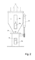
- Fig. 2
- den Granulatabscheider von vorne,
- Fig.3a,b:
- eine Druckluftförderanlage unter Verwendung des Granulatabscheiders der
Figuren 1 und2 in verschiedenen Betriebszuständen und - Fig. 4
- eine Druckluftförderanlage mit anderem Aufbau ebenfalls unter Verwendung des Granulatabscheiders der
Figuren 1 und 2 .
- Fig. 1a, b:
- the granulate separator in the side view in different operating states,
- Fig. 2
- the granulate separator from the front,
- 3a, b:
- a compressed air conveying system using the granule separator
FIGS. 1 and2 in different operating states and - Fig. 4
- a Druckluftförderanlage with another structure also using the granule separator
FIGS. 1 and2 ,
Zunächst soll anhand der
- Der primäre Zweck besteht darin - wie in
Fig. 3a dargestellt - ein z.B.Granulat 4 an einen gewünschten Ort zu befördern.
- The primary purpose is - as in
Fig. 3a represented - to transport agranule 4, for example, to a desired location.
Das Granulat 4 wird dabei in einem oben offenen Vorratsbehälter 7, beispielsweise einem Sack oder einem Fass, angeliefert und das Granulat soll in der benötigten Menge zum Beispiel einer Kunststoffspritzgussmaschine oder zuvor einem Granulattrockner zugeführt werden.The
Dabei besteht häufig die Notwendigkeit, aus mehreren zur Verfügung stehenden Vorratsbehältern 7, die unterschiedliche Granulate 4 enthalten, hintereinander kurzzeitig wechselnde Granulate zuzufördern, sodass sich in der Praxis im Gegensatz zu den
Das Fördern erfolgt mittels Ansaugen des Granulates 4 aus dem Vorratsbehälter 7 über eine Sauglanze 16 mittels Förderluft 3, die das angesaugte Granulat in der Förderluft von der Sauglanze 16 über eine meist als Schlauch ausgebildete Förderleitung 15 in den Granulatabscheider 1 befördert, der mit seiner unteren Ausgabeöffnung 31 oberhalb der gewünschten Bedarfsstelle, z.B. der Spritzgussmaschine, aufgebaut ist.The conveying takes place by means of suction of the
In diesem Fall besteht das Innere des Granulatabscheiders 1, der Granulat-Sammelbereich, aus dem Granulat-Zwischenbehälter 9 oben und dem darunter liegenden Granulat-Endbehälter 14, mit einer verschließbaren Granulatklappe 6 dazwischen.In this case, the interior of the
In diesem Fall mündet die Förderleitung 15 in der Oberseite des oberen Granulat-Zwischenbehälters 9, der - wie besser in den
Von der Auslassöffnung 18 wird die Förderluft 3 über eine Staubleitung 20, die ebenfalls meist wieder als Schlauch ausgebildet ist, einem Staubsammelbehälter 12 zugeführt, in dessen Auslassöffnung sich ein Filter 2 zum Zurückhalten des Staubanteiles aus der Förderluft 3 befindet. Die Förderluft durchdringt somit den Filter 2 und tritt aus in die Umgebung, während sich der in der Staubleitung 20 in der Förderluft 3 noch enthaltene Staub 11 am Boden des Staubbehälters 12 absetzt.From the outlet port 18, the conveying
Die gesamte Anlage wird mittels Druckluft betrieben, indem auch der Unterdruck, der für die Förderluft 3 benötigt wird, mittels Druckluft erzeugt wird, und zwar mittels eines Transportejektors 21, die beim Aufbau der
- Dabei handelt es sich um ein Winkelstück mit einer meist düsenförmigen Auslassöffnung, welches so in eine Seitenwand des Staubableitungs-Stutzens eingebaut ist, dass die
Auslassöffnung dieses Transportejektors 21 mittig im meist runden Querschnitt des Stutzens angeordnet ist und Druckluft inStrömungsrichtung 10, also die Verlaufsrichtung der Staubleitung 20 inRichtung Staubsammelbehälter 12, abgibt, wodurch stromaufwärts des Transportejektors ein starker Unterdruck erzeugt wird, der über den Granulat-Zwischenbehälter 9 und dieFörderleitung 15 bis indie Sauglanze 16 zurück wirkt und an deren freien offenen Ende einAnsaugen von Granulat 4im Vorratsbehälter 7 bewirkt.
- It is an elbow with a mostly nozzle-shaped outlet opening, which is installed in a side wall of the dust discharge nozzle, that the outlet opening of this
transport ejector 21 is arranged centrally in the mostly round cross-section of the nozzle and compressed air in theflow direction 10, ie the direction of theDust line 20 in the direction ofdust collection container 12, discharges, whereby a strong negative pressure is generated upstream of the transport ejector, which acts on the granulateintermediate container 9 and thedelivery line 15 back into thesuction lance 16 and at the free open end of a suction ofgranules 4 in thereservoir 7 causes.
Die dafür benötigte Druckluft wird von einer Druckluftquelle 17 zur Verfügung gestellt, die ein eigener Druckluftkompressor sein kann oder ein Anschluss an ein größeres Druckluftnetz. Die Abgabe der Druckluft an die einzelnen Stellen der Druckluftförderanlage wird von einer Steuerung 22 gesteuert:
- Mit Druckluft wird nicht nur der Transportejektor 21 beliefert, sondern des Weiteren ein Aufwirbelungs-
Ejektor 28, die im unteren Bereich des Granulat-Zwischenbehälters 9 in dessen Frontwand eingebaut ist und auf die schräg gestellte Rückwand des Granulat-Zwischenbehälters 9 gerichtet ist.
- With compressed air not only the
transport ejector 21 is supplied, but also aAufwirbelungs ejector 28, which is installed in the lower region of the granularintermediate container 9 in the front wall and is directed to the inclined rear wall of the granularintermediate container 9.
Mit Druckluft wird ferner die Granulatklappe 6 angesteuert, die die Granulatöffnung 25 zwischen dem Granulat-Zwischenbehälter 9 und dem Granulat-Endbehälter 14 verschließt. Dabei ist bei fehlender Druckluftbeaufschlagung die Granulatklappe 6 im offenen Zustand und wird mittels Druckluftbeaufschlagung geschlossen.With compressed air, the granule flap 6 is further controlled, the
Die Mündungen der ein oder mehreren Förderleitungen 15 in der Oberseite, nämlich dem Deckel 27, des Granulatabscheiders 1 sind mittels je einer Verschlussklappe 32 verschließbar, die schwerkraft-betätigt an der Unterseite der Auslassöffnung anliegt.The mouths of the one or
- Dabei ist die Granulatklappe 6 mittels Druckluftbeaufschlagung geschlossen und über
den Transportejektor 21 wird Druckluft über die zu diesen Druckluftdüsen 21 führende unverzweigte Druckluftleitung 26a eingeschossen.
- In this case, the granule flap 6 is closed by means of pressurized air, and compressed air is injected via the
transport ejector 21 via the unbranchedcompressed air line 26a leading to these compressed-air nozzles 21.
Denn die aus dem Transportejektor 21 ausströmende Druckluft dient dem Aufbau des Unterdrucks in der Förderleitung 15 und damit dem Ansaugen des Granulates 4. Der Unterdruck stromaufwärts des Transportejektors 21 sorgt auch dafür, dass die schwerkraft-betätigte Verschlussklappe 32 sich öffnet, da dies die einzige Stelle des ansonsten geschlossenen Granulat-Zwischenbehälters 9 ist, aus der Luft nachströmen kann, die von dem Transportejektor 21 angesaugt wird.Because the air flowing out of the
Auf diese Art und Weise sammelt sich das Granulat 4 am Boden des Granulat-Zwischenbehälters 9 immer mehr an, während der in der Förderluft 3 vorhandene Staubanteil durch die Staubleitung 20 abgeführt wird.In this way, the
Um die Entstaubung zu verbessern, wird - jedoch nicht während des Fördervorganges, und eventuell nur periodisch - Druckluft über den Aufwirbelungs-Ejektor 28 in das abgelagerte Granulat 4 eingeschossen und dieses erneut aufgewirbelt, sodass noch an den Granulatpartikeln anhaftender Staub wieder frei wird und über die Staubleitung 20 abgeführt werden kann. Dabei ist die Granulatklappe 6 geschlossen oder wird zeitgleich geöffnet. Das Absaugen des Staubes erfolgt, indem auch dem Transportejektor 21 etwas Druckluft zugeführt wird, beide versorgt über die Leitungsverzweigung 33 und die Leitungen 26b, aber mit einer Drossel 13 im Ast zum Transportejektor 21.In order to improve the dedusting is - but not during the delivery process, and possibly only periodically - injected via the fluidizing
Der Druckluftstrahl des Aufwirbelungs-Ejektors 28 ist dabei auf den schräg gestellten unteren Teil der Rückwand des Granulat-Zwischenbehälters 9 gerichtet, die dadurch einem starken Verschleiß unterliegt, weshalb sie von der Außenseite her durch eine Metallplatte 30 verstärkt ist.The compressed air jet of the
Die Neigung der Rückwand im unteren Bereich ist dabei so bemessen, dass der von dort nach oben abgelenkte Druckluftstrahl weiter oben auf das im senkrechten Teil der Rückwand eingelassene Sieb 5 der Auslassöffnung 18 auftrifft, und dieses von anhaftenden Verschmutzungen, vorzugsweise anhaftendem Staub, ebenfalls befreit, sowohl durch direkt dort auftreffende Druckluft aus dem Aufwirbelungs-Ejektor 28 als auch durch von dieser mitgerissene und gegen das Sieb 5 geschleuderte Granulatpartikel.The inclination of the rear wall in the lower area is so dimensioned that from there deflected upward compressed air jet impinges further up on the recessed in the vertical part of the rear wall sieve 5 of the outlet opening 18, and this of adhering dirt, preferably adhering dust, also freed, both by directly there impinging compressed air from the fluidizing
Das Füllen des Granulat-Zwischenbehälters 9 erfolgt solange, bis der auf der Außenseite des durchsichtigen Fensters 8a in der Vorderwand des Granulat-Zwischenbehälters 9 angeordnete Füllstandssensor 19a einen ausreichenden Füllstand im Granulat-Zwischenbehälter 9 an die Steuerung 22 meldet und diese die Druckluftzufuhr zum Transportejektor 21 abschaltet.The filling of the
Anschließend wird - wie in
Bei diesem Vorgang kann zusätzlich wiederum durch die beiden Druckluftdüsen 21, 28 über die Leitungen 26b Druckluft eingeschossen werden, um während des Herabfallens des Granulates 4 ebenfalls wieder enthaltene Reste an Staub von den Granulatkörnern zu lösen und durch die Staubleitung 20 abzuführen. Die Verschlussklappe 32 bleibt dabei schwerkraftbedingt geschlossen, da ein Nachströmen von Luft aus dem Granulatendbehälter 14 möglich ist.In this process, compressed air can in turn also be injected through the two compressed-
Anschließend schließt sich die Granulatklappe 6 wieder und der Vorgang gemäß
In den Leitungen 26a,b sind jeweils Rückschlagventile eingebaut.In the
Je nach den konkreten Verhältnissen wie Leitungsquerschnitten, Leitungslängen und dem Druck der Druckluft sowie dem Durchmesser der Druckluftdüse, kann der stromabwärts des Filters 2 angeordnete Transportejektor 21 auch die einzige den Unterdruck zur Verfügung stellende Druckluftdüse sein.Depending on the specific conditions such as line cross sections, line lengths and the pressure of the compressed air and the diameter of the compressed air nozzle, the
Dabei werden die beiden Transportejektoren 21 über eine verzweigte Leitung 26a versorgt, der übrige Aufbau ist identisch.Here, the two
Neben den bereits beschriebenen Details des Granulatabscheiders 1 zeigen die
- So ist der Oberteil des
Granulatabscheiders 1, also der Granulat-Zwischenbehälter 9 samt den Anschlussstutzen für zwei Förderleitungen 15 und eine Staubleitung 20 sowie derdarin befestigte Transportejektor 21 als Oberteil gegenüber dem Unterteil, der im Wesentlichen den Granulat-Endbehälter 14 und die Granulatklappe 6 umfasst, abklappbar nach hinten um eine Achse 24 an der Rückseite des Granulatsammelbehälters.
- Thus, the upper part of the
granulate separator 1, ie the granulateintermediate container 9 together with the connection piece for twodelivery lines 15 and adust line 20 and thetransport ejector 21 attached therein as the upper part relative to the lower part, which is essentially thefinal granulate container 14 and the granule flap 6, hinged to the rear about anaxis 24 at the rear of the granule collecting container.
Dadurch ist vor allem das Innere des Granulat-Endbehälters 14 für Reinigungszwecke gut zugänglich ohne den gesamten Granulatabscheider 1 von der darunter liegenden Maschine abbauen zu müssen.As a result, especially the interior of the
Der Pneumatikzylinder 23, der mit dem freien Ende seiner Kolbenstange an einem die Granulatklappe 6 betätigenden Hebel befestigt ist, befindet sich seitlich an der Außenseite des Granulatabscheiders 1 und ist mit dem oberen Ende an dessen Granulat-Zwischenbehälter 9 befestigt.The
Die Anordnung ist dabei so gewählt, dass beim Abklappen des Oberteiles nach hinten sich die Granulatklappe 6 über die Horizontale hinaus nach oben dreht und deshalb der Bereich darunter gut gereinigt werden kann, oder auch durch zusätzliche Beaufschlagung des Pneumatikzylinders 23 mit Druckluft die Granulatklappe 6 nach unten verschwenkt in den Granulatendbehälter 14 hinein verbracht werden kann.The arrangement is chosen so that when folding down the upper part of the granule flap 6 rotates beyond the horizontal upwards and therefore the area below can be cleaned well, or by additional pressurization of the
Die
- 11
- Granulatabscheidergranule
- 22
- Filterfilter
- 33
- Förderluftconveying air
- 44
- Granulatgranules
- 55
- Siebscree
- 66
- Granulatklappegranules flap
- 77
- Vorratsbehälterreservoir
- 8a, b8a, b
- Fensterwindow
- 99
- Granulat-ZwischenbehälterGranular intermediate container
- 1010
- Strömungsrichtungflow direction
- 1111
- Staubdust
- 1212
- Staub-SammelbehälterDust collecting
- 1313
- Drosselthrottle
- 1414
- Granulat-EndbehälterGranule final container
- 1515
- Förderleitungdelivery line
- 1616
- Sauglanzelance
- 1717
- DruckluftquelleCompressed air source
- 1818
- Auslassöffnungoutlet
- 19a, b19a, b
- Füllstandssensorlevel sensor
- 2020
- Staubleitungdust line
- 2121
- TransportejektorTransportejektor
- 2222
- Steuerungcontrol
- 2323
- Pneumatikzylinderpneumatic cylinder
- 2424
- Achseaxis
- 2525
- Granulatöffnunggranules opening
- 26a, b26a, b
- DruckluftleitungCompressed air line
- 2727
- Deckelcover
- 2828
- Aufwirbelungs-EjektorAufwirbelungs ejector
- 2929
- Achseaxis
- 3030
- Metallplattemetal plate
- 3131
- Ausgabeöffnungdischarge opening
- 3232
- Verschlussklappeflap
- 3333
- Leitungsverzweigungmanifold
Claims (15)
dadurch gekennzeichnet, dass
nur stromabwärts des Siebes (5), insbesondere im Anfang der vom Sieb (5) wegführenden Staubleitung (20), ein Transportejektor (21) angeordnet ist.
characterized in that
only downstream of the screen (5), in particular in the beginning of the dust line (20) leading away from the screen (5), a transport ejector (21) is arranged.
dadurch gekennzeichnet, dass
characterized in that
dadurch gekennzeichnet, dass
characterized in that
dadurch gekennzeichnet, dass
der freie Versorgungsquerschnitt, z. B. der Drossel (13), für den Transportejektor (21) mindestens um den Faktor 1,2, besser mindestens um den Faktor 1,5, kleiner ist als die Querschnittsfläche des Aufwirbelungs-Ejektors (28), insbesondere jedoch höchstens um den Faktor 3,0, besser höchstens um den Faktor 2,0.Granule separator according to one of the preceding claims,
characterized in that
the free supply cross section, z. B. the throttle (13), for the transport ejector (21) at least by a factor of 1.2, better at least by a factor of 1.5, smaller than the cross-sectional area of the fluidizing ejector (28), but in particular at most by the factor 3.0, better at most by a factor of 2.0.
dadurch gekennzeichnet, dass
die Querschnittsfläche der Staubleitung (20) mindestens um den Faktor 400, besser mindestens um den Faktor 500, größer ist als die Querschnittsfläche des Transportejektors (21), insbesondere jedoch höchstens um den Faktor 800, besser höchstens um den Faktor 700.Granule separator according to one of the preceding claims,
characterized in that
the cross-sectional area of the dust duct (20) is greater than the cross-sectional area of the transport ejector (21) by at least a factor of 400, better by at least a factor of 500, in particular at most by a factor of 800, better at most by a factor of 700.
dadurch gekennzeichnet, dass
der Granulat-Zwischenbehälter (9) um eine horizontal liegende Achse (29), die insbesondere hinter der Granulatöffnung (25) angeordnet ist, gegenüber dem Granulat-Behälter (14) klappbar ist, und insbesondere die Granulatklappe (6) am Granulat-Endbehälterer (14) befestigt istGranule separator according to one of the preceding claims,
characterized in that
the granulate intermediate container (9) about a horizontal axis (29), which is arranged in particular behind the granule opening (25), opposite the granule container (14) is foldable, and in particular the granule flap (6) on granules final container ( 14) is attached
dadurch gekennzeichnet, dass
der Granulatsammelbereich, insbesondere der Granulat-Zwischenbehälter (9), auf der Oberseite von einem Deckel (27) verschlossen ist, der abnehmbar und insbesondere mittels Spannverschlüssen fixiert ist.Granule separator according to one of the preceding claims,
characterized in that
the granule collecting area, in particular the intermediate granulate container (9), is closed on the upper side by a cover (27) which is removable and in particular fixed by means of clamping closures.
dadurch gekennzeichnet, dass
characterized in that
dadurch gekennzeichnet, dass
im Granulatabscheider (1) wenigstens zwei Förder-Leitungen (15) münden zur Anlieferung unterschiedlicher Fördergute und insbesondere die Verschlusseinrichtungen, insbesondere die Verschlussklappen der Förder-Leitungen (15) zwangsgesteuert durch eine Steuerung (22) sind.Granule separator according to one of the preceding claims,
characterized in that
in Granulatabscheider (1) at least two conveyor lines (15) lead to the delivery of different Fördergute and in particular the closure devices, in particular the flaps of the conveyor lines (15) are positively controlled by a controller (22).
dadurch gekennzeichnet, dass
der Granulatabscheider (1) nach einem der vorhergehenden Ansprüche ausgebildet ist.
characterized in that
the granulate separator (1) is designed according to one of the preceding claims.
dadurch gekennzeichnet, dass
mittels Einschießen von Druckluft in den Granulatsammelbereich bei geschlossenem Granulat-Auslauf und/oder bei offenem Granulat-Auslauf ein Anhaften von Granulat im Sammelbereich, insbesondere im Zwischenbehälter (9), beseitigt wird.
characterized in that
By injecting compressed air into the granule collecting area with the granule outlet closed and / or with an open granular outlet, the adhesion of granules in the collecting area, in particular in the intermediate container (9), is eliminated.
dadurch gekennzeichnet, dass
das Einschießen von Druckluft in den Granulatsammelbereich sowie in die Staubleitung (20) zur Erzeugung von Unterdruck gleichzeitig mithilfe des gleichen Ventils gesteuert wird.Method according to claim 14,
characterized in that
the injection of compressed air into the granule collecting area and into the dust line (20) for generating negative pressure is simultaneously controlled by means of the same valve.
Priority Applications (1)
| Application Number | Priority Date | Filing Date | Title |
|---|---|---|---|
| EP20110194881 EP2607274B1 (en) | 2011-12-21 | 2011-12-21 | Separator for granular material and compressed air supply device with separator for granular material |
Applications Claiming Priority (1)
| Application Number | Priority Date | Filing Date | Title |
|---|---|---|---|
| EP20110194881 EP2607274B1 (en) | 2011-12-21 | 2011-12-21 | Separator for granular material and compressed air supply device with separator for granular material |
Publications (2)
| Publication Number | Publication Date |
|---|---|
| EP2607274A1 true EP2607274A1 (en) | 2013-06-26 |
| EP2607274B1 EP2607274B1 (en) | 2014-08-13 |
Family
ID=45421946
Family Applications (1)
| Application Number | Title | Priority Date | Filing Date |
|---|---|---|---|
| EP20110194881 Not-in-force EP2607274B1 (en) | 2011-12-21 | 2011-12-21 | Separator for granular material and compressed air supply device with separator for granular material |
Country Status (1)
| Country | Link |
|---|---|
| EP (1) | EP2607274B1 (en) |
Cited By (4)
| Publication number | Priority date | Publication date | Assignee | Title |
|---|---|---|---|---|
| CN107720282A (en) * | 2017-08-24 | 2018-02-23 | 无锡康柏斯机械科技有限公司 | A kind of intelligent particle conveyer |
| IT201700117864A1 (en) * | 2017-10-18 | 2019-04-18 | Enecolab S R L | SUPPLY DEVICE FOR GRANULAR MATERIAL AND ITS SUPPLY PROCEDURE |
| US20220008958A1 (en) * | 2018-10-01 | 2022-01-13 | HELIOS Gerätebau für Kunststofftechnik GmbH | Apparatus and method for de-dusting bulk materials |
| DE202021105873U1 (en) | 2021-10-27 | 2023-01-30 | Maschinenbau Hebrock GmbH | Edge banding machine with pneumatic glue granulate transport |
Families Citing this family (1)
| Publication number | Priority date | Publication date | Assignee | Title |
|---|---|---|---|---|
| CN110467002A (en) * | 2018-05-12 | 2019-11-19 | 襄阳市飞钟粮食机械有限公司 | A kind of grain automatic charging machine |
Citations (8)
| Publication number | Priority date | Publication date | Assignee | Title |
|---|---|---|---|---|
| DE2709746A1 (en) * | 1977-03-05 | 1978-09-07 | Tesch Kg E | Automatic feeding of plastics granulate to processing machine - from drying hopper kept at high pressure with outlet kept at high vacuum to prevent clogging |
| NL7712041A (en) * | 1977-11-01 | 1979-05-03 | Handelmaatschappij Voorheen Be | Suction equipment for powdery material - incorporates ejector type suction pump and cyclone type separator |
| GB2096965A (en) * | 1981-02-09 | 1982-10-27 | Acousti Therm Ceilings & Linin | Pneumatic conveyance of material |
| DE3805531A1 (en) * | 1988-02-23 | 1989-08-31 | Intec Maschinenbau Gmbh | Method for conveying powder and apparatus for carrying out this method |
| DE29815528U1 (en) * | 1998-08-31 | 1998-12-24 | Werner Koch Maschinentechnik Gmbh, 75228 Ispringen | Device for conveying and dosing a powdery or granular plastic material |
| DE20100972U1 (en) * | 2001-01-19 | 2002-05-23 | Albrecht, Friedhelm, 57462 Olpe | Device for suction of coarse material |
| WO2005102882A1 (en) * | 2004-04-20 | 2005-11-03 | Volkmann Gmbh | Method and device for rendering vacuum conveyors inert |
| EP2045199A1 (en) * | 2007-10-02 | 2009-04-08 | Klaus Wilhelm | Compressed air supply device for bulk material |
-
2011
- 2011-12-21 EP EP20110194881 patent/EP2607274B1/en not_active Not-in-force
Patent Citations (8)
| Publication number | Priority date | Publication date | Assignee | Title |
|---|---|---|---|---|
| DE2709746A1 (en) * | 1977-03-05 | 1978-09-07 | Tesch Kg E | Automatic feeding of plastics granulate to processing machine - from drying hopper kept at high pressure with outlet kept at high vacuum to prevent clogging |
| NL7712041A (en) * | 1977-11-01 | 1979-05-03 | Handelmaatschappij Voorheen Be | Suction equipment for powdery material - incorporates ejector type suction pump and cyclone type separator |
| GB2096965A (en) * | 1981-02-09 | 1982-10-27 | Acousti Therm Ceilings & Linin | Pneumatic conveyance of material |
| DE3805531A1 (en) * | 1988-02-23 | 1989-08-31 | Intec Maschinenbau Gmbh | Method for conveying powder and apparatus for carrying out this method |
| DE29815528U1 (en) * | 1998-08-31 | 1998-12-24 | Werner Koch Maschinentechnik Gmbh, 75228 Ispringen | Device for conveying and dosing a powdery or granular plastic material |
| DE20100972U1 (en) * | 2001-01-19 | 2002-05-23 | Albrecht, Friedhelm, 57462 Olpe | Device for suction of coarse material |
| WO2005102882A1 (en) * | 2004-04-20 | 2005-11-03 | Volkmann Gmbh | Method and device for rendering vacuum conveyors inert |
| EP2045199A1 (en) * | 2007-10-02 | 2009-04-08 | Klaus Wilhelm | Compressed air supply device for bulk material |
Cited By (5)
| Publication number | Priority date | Publication date | Assignee | Title |
|---|---|---|---|---|
| CN107720282A (en) * | 2017-08-24 | 2018-02-23 | 无锡康柏斯机械科技有限公司 | A kind of intelligent particle conveyer |
| IT201700117864A1 (en) * | 2017-10-18 | 2019-04-18 | Enecolab S R L | SUPPLY DEVICE FOR GRANULAR MATERIAL AND ITS SUPPLY PROCEDURE |
| US20220008958A1 (en) * | 2018-10-01 | 2022-01-13 | HELIOS Gerätebau für Kunststofftechnik GmbH | Apparatus and method for de-dusting bulk materials |
| US11925959B2 (en) * | 2018-10-01 | 2024-03-12 | HELIOS Gerätebau für Kunststofftechnik GmbH | Apparatus and method for de-dusting bulk materials |
| DE202021105873U1 (en) | 2021-10-27 | 2023-01-30 | Maschinenbau Hebrock GmbH | Edge banding machine with pneumatic glue granulate transport |
Also Published As
| Publication number | Publication date |
|---|---|
| EP2607274B1 (en) | 2014-08-13 |
Similar Documents
| Publication | Publication Date | Title |
|---|---|---|
| EP2045199B1 (en) | Compressed air supply device for bulk material | |
| DE202011052400U1 (en) | Compressed air conveyor system for bulk material | |
| DE102012108907B4 (en) | Method and device for dedusting bulk materials by means of ionization | |
| EP2045003A1 (en) | Device for conveying and mixing bulk material | |
| EP1953098A1 (en) | Emptying device for powder sacks for powder spray coating facilities | |
| EP2607274B1 (en) | Separator for granular material and compressed air supply device with separator for granular material | |
| EP3826776A1 (en) | Apparatus and method for de-dusting bulk materials | |
| DE102007047119A1 (en) | Granulate separator for use in air conveyor of compressed air supply device, has feed pipe opened out in separator for delivering material to be conveyed, and compressed air outlet opened out in feed pipe upstream of separator | |
| DE3900664C2 (en) | ||
| DE3924566A1 (en) | Arrangement for separating metal particles from granular bulk material - has deflector sealing delivery channel to pass flow to collector when metal is detected | |
| DE102009015271A1 (en) | Machining device for bulk material | |
| EP1730059B1 (en) | Device and method for pneumatically conveying fine particle bulk materials | |
| DE202007013754U1 (en) | Compressed air conveyor system for bulk material | |
| DE202011110148U1 (en) | Compressed air conveyor system for bulk material | |
| DE2136328A1 (en) | DEVICE FOR PNEUMATIC FEEDING OF SEVERAL RECEPTION POINTS WITH GOODS FROM ONE OR MORE STORAGE CONTAINERS | |
| DE10161591B4 (en) | Method for the automatic emptying and refilling of granule funnels for production conversion | |
| EP3434632A1 (en) | Device and method for conveying material consisting predominantly of solid particles, in particular powder material, for example dry mortar | |
| EP0755726A1 (en) | Method and device for sorting bulk material | |
| CH690573A5 (en) | Method and apparatus for avoiding Produktestaub- or gas outlet products at filling with solid or Flüssigkeitsdosiersystemen. | |
| DE2252870A1 (en) | METHOD AND DEVICE FOR PNEUMATIC CONVEYING | |
| DE102020107898A1 (en) | Exchangeable adapter, handling unit with exchangeable adapter, method for operating such a handling unit | |
| DE69412793T2 (en) | METHOD AND SYSTEM FOR PROCESSING CAN | |
| DE10013976C1 (en) | Pneumatic conveying device for bulk material has devices to supply pigs, which are moved through conveyor line and unit to separate pigs, which has removal vessel with grating | |
| DE4219616A1 (en) | Pneumatic conveyor system for loose materials - uses intermittent gas streams to form and separate material build-ups through rhythmic introduction of gas to produce suction. | |
| DE102004014059A1 (en) | Apparatus and method for pneumatic conveying of finely divided bulk materials |
Legal Events
| Date | Code | Title | Description |
|---|---|---|---|
| AK | Designated contracting states |
Kind code of ref document: A1 Designated state(s): AL AT BE BG CH CY CZ DE DK EE ES FI FR GB GR HR HU IE IS IT LI LT LU LV MC MK MT NL NO PL PT RO RS SE SI SK SM TR |
|
| AX | Request for extension of the european patent |
Extension state: BA ME |
|
| PUAI | Public reference made under article 153(3) epc to a published international application that has entered the european phase |
Free format text: ORIGINAL CODE: 0009012 |
|
| 17P | Request for examination filed |
Effective date: 20131219 |
|
| RBV | Designated contracting states (corrected) |
Designated state(s): AL AT BE BG CH CY CZ DE DK EE ES FI FR GB GR HR HU IE IS IT LI LT LU LV MC MK MT NL NO PL PT RO RS SE SI SK SM TR |
|
| GRAP | Despatch of communication of intention to grant a patent |
Free format text: ORIGINAL CODE: EPIDOSNIGR1 |
|
| INTG | Intention to grant announced |
Effective date: 20140225 |
|
| GRAS | Grant fee paid |
Free format text: ORIGINAL CODE: EPIDOSNIGR3 |
|
| GRAA | (expected) grant |
Free format text: ORIGINAL CODE: 0009210 |
|
| AK | Designated contracting states |
Kind code of ref document: B1 Designated state(s): AL AT BE BG CH CY CZ DE DK EE ES FI FR GB GR HR HU IE IS IT LI LT LU LV MC MK MT NL NO PL PT RO RS SE SI SK SM TR |
|
| REG | Reference to a national code |
Ref country code: GB Ref legal event code: FG4D Free format text: NOT ENGLISH |
|
| REG | Reference to a national code |
Ref country code: CH Ref legal event code: EP Ref country code: AT Ref legal event code: REF Ref document number: 682077 Country of ref document: AT Kind code of ref document: T Effective date: 20140815 |
|
| REG | Reference to a national code |
Ref country code: IE Ref legal event code: FG4D Free format text: LANGUAGE OF EP DOCUMENT: GERMAN |
|
| REG | Reference to a national code |
Ref country code: DE Ref legal event code: R096 Ref document number: 502011004022 Country of ref document: DE Effective date: 20141002 |
|
| REG | Reference to a national code |
Ref country code: NL Ref legal event code: VDEP Effective date: 20140813 |
|
| REG | Reference to a national code |
Ref country code: LT Ref legal event code: MG4D |
|
| PG25 | Lapsed in a contracting state [announced via postgrant information from national office to epo] |
Ref country code: BG Free format text: LAPSE BECAUSE OF FAILURE TO SUBMIT A TRANSLATION OF THE DESCRIPTION OR TO PAY THE FEE WITHIN THE PRESCRIBED TIME-LIMIT Effective date: 20141113 Ref country code: NO Free format text: LAPSE BECAUSE OF FAILURE TO SUBMIT A TRANSLATION OF THE DESCRIPTION OR TO PAY THE FEE WITHIN THE PRESCRIBED TIME-LIMIT Effective date: 20141113 Ref country code: PT Free format text: LAPSE BECAUSE OF FAILURE TO SUBMIT A TRANSLATION OF THE DESCRIPTION OR TO PAY THE FEE WITHIN THE PRESCRIBED TIME-LIMIT Effective date: 20141215 Ref country code: LT Free format text: LAPSE BECAUSE OF FAILURE TO SUBMIT A TRANSLATION OF THE DESCRIPTION OR TO PAY THE FEE WITHIN THE PRESCRIBED TIME-LIMIT Effective date: 20140813 Ref country code: ES Free format text: LAPSE BECAUSE OF FAILURE TO SUBMIT A TRANSLATION OF THE DESCRIPTION OR TO PAY THE FEE WITHIN THE PRESCRIBED TIME-LIMIT Effective date: 20140813 Ref country code: SE Free format text: LAPSE BECAUSE OF FAILURE TO SUBMIT A TRANSLATION OF THE DESCRIPTION OR TO PAY THE FEE WITHIN THE PRESCRIBED TIME-LIMIT Effective date: 20140813 Ref country code: FI Free format text: LAPSE BECAUSE OF FAILURE TO SUBMIT A TRANSLATION OF THE DESCRIPTION OR TO PAY THE FEE WITHIN THE PRESCRIBED TIME-LIMIT Effective date: 20140813 Ref country code: GR Free format text: LAPSE BECAUSE OF FAILURE TO SUBMIT A TRANSLATION OF THE DESCRIPTION OR TO PAY THE FEE WITHIN THE PRESCRIBED TIME-LIMIT Effective date: 20141114 |
|
| PG25 | Lapsed in a contracting state [announced via postgrant information from national office to epo] |
Ref country code: LV Free format text: LAPSE BECAUSE OF FAILURE TO SUBMIT A TRANSLATION OF THE DESCRIPTION OR TO PAY THE FEE WITHIN THE PRESCRIBED TIME-LIMIT Effective date: 20140813 Ref country code: RS Free format text: LAPSE BECAUSE OF FAILURE TO SUBMIT A TRANSLATION OF THE DESCRIPTION OR TO PAY THE FEE WITHIN THE PRESCRIBED TIME-LIMIT Effective date: 20140813 Ref country code: IS Free format text: LAPSE BECAUSE OF FAILURE TO SUBMIT A TRANSLATION OF THE DESCRIPTION OR TO PAY THE FEE WITHIN THE PRESCRIBED TIME-LIMIT Effective date: 20141213 Ref country code: CY Free format text: LAPSE BECAUSE OF FAILURE TO SUBMIT A TRANSLATION OF THE DESCRIPTION OR TO PAY THE FEE WITHIN THE PRESCRIBED TIME-LIMIT Effective date: 20140813 Ref country code: HR Free format text: LAPSE BECAUSE OF FAILURE TO SUBMIT A TRANSLATION OF THE DESCRIPTION OR TO PAY THE FEE WITHIN THE PRESCRIBED TIME-LIMIT Effective date: 20140813 |
|
| PG25 | Lapsed in a contracting state [announced via postgrant information from national office to epo] |
Ref country code: NL Free format text: LAPSE BECAUSE OF FAILURE TO SUBMIT A TRANSLATION OF THE DESCRIPTION OR TO PAY THE FEE WITHIN THE PRESCRIBED TIME-LIMIT Effective date: 20140813 |
|
| PG25 | Lapsed in a contracting state [announced via postgrant information from national office to epo] |
Ref country code: EE Free format text: LAPSE BECAUSE OF FAILURE TO SUBMIT A TRANSLATION OF THE DESCRIPTION OR TO PAY THE FEE WITHIN THE PRESCRIBED TIME-LIMIT Effective date: 20140813 Ref country code: IT Free format text: LAPSE BECAUSE OF FAILURE TO SUBMIT A TRANSLATION OF THE DESCRIPTION OR TO PAY THE FEE WITHIN THE PRESCRIBED TIME-LIMIT Effective date: 20140813 Ref country code: RO Free format text: LAPSE BECAUSE OF FAILURE TO SUBMIT A TRANSLATION OF THE DESCRIPTION OR TO PAY THE FEE WITHIN THE PRESCRIBED TIME-LIMIT Effective date: 20140813 Ref country code: SK Free format text: LAPSE BECAUSE OF FAILURE TO SUBMIT A TRANSLATION OF THE DESCRIPTION OR TO PAY THE FEE WITHIN THE PRESCRIBED TIME-LIMIT Effective date: 20140813 Ref country code: DK Free format text: LAPSE BECAUSE OF FAILURE TO SUBMIT A TRANSLATION OF THE DESCRIPTION OR TO PAY THE FEE WITHIN THE PRESCRIBED TIME-LIMIT Effective date: 20140813 Ref country code: CZ Free format text: LAPSE BECAUSE OF FAILURE TO SUBMIT A TRANSLATION OF THE DESCRIPTION OR TO PAY THE FEE WITHIN THE PRESCRIBED TIME-LIMIT Effective date: 20140813 |
|
| REG | Reference to a national code |
Ref country code: DE Ref legal event code: R082 Ref document number: 502011004022 Country of ref document: DE Representative=s name: PATENTANWAELTE WEICKMANN & WEICKMANN, DE Ref country code: DE Ref legal event code: R082 Ref document number: 502011004022 Country of ref document: DE Representative=s name: WEICKMANN & WEICKMANN PATENTANWAELTE - RECHTSA, DE Ref country code: DE Ref legal event code: R082 Ref document number: 502011004022 Country of ref document: DE Representative=s name: WEICKMANN & WEICKMANN PATENT- UND RECHTSANWAEL, DE |
|
| REG | Reference to a national code |
Ref country code: DE Ref legal event code: R097 Ref document number: 502011004022 Country of ref document: DE |
|
| PG25 | Lapsed in a contracting state [announced via postgrant information from national office to epo] |
Ref country code: PL Free format text: LAPSE BECAUSE OF FAILURE TO SUBMIT A TRANSLATION OF THE DESCRIPTION OR TO PAY THE FEE WITHIN THE PRESCRIBED TIME-LIMIT Effective date: 20140813 |
|
| PLBE | No opposition filed within time limit |
Free format text: ORIGINAL CODE: 0009261 |
|
| STAA | Information on the status of an ep patent application or granted ep patent |
Free format text: STATUS: NO OPPOSITION FILED WITHIN TIME LIMIT |
|
| PG25 | Lapsed in a contracting state [announced via postgrant information from national office to epo] |
Ref country code: BE Free format text: LAPSE BECAUSE OF NON-PAYMENT OF DUE FEES Effective date: 20141231 |
|
| 26N | No opposition filed |
Effective date: 20150515 |
|
| PG25 | Lapsed in a contracting state [announced via postgrant information from national office to epo] |
Ref country code: LU Free format text: LAPSE BECAUSE OF FAILURE TO SUBMIT A TRANSLATION OF THE DESCRIPTION OR TO PAY THE FEE WITHIN THE PRESCRIBED TIME-LIMIT Effective date: 20141221 |
|
| REG | Reference to a national code |
Ref country code: CH Ref legal event code: PL |
|
| REG | Reference to a national code |
Ref country code: IE Ref legal event code: MM4A |
|
| REG | Reference to a national code |
Ref country code: FR Ref legal event code: ST Effective date: 20150831 |
|
| PG25 | Lapsed in a contracting state [announced via postgrant information from national office to epo] |
Ref country code: CH Free format text: LAPSE BECAUSE OF NON-PAYMENT OF DUE FEES Effective date: 20141231 Ref country code: LI Free format text: LAPSE BECAUSE OF NON-PAYMENT OF DUE FEES Effective date: 20141231 Ref country code: IE Free format text: LAPSE BECAUSE OF NON-PAYMENT OF DUE FEES Effective date: 20141221 |
|
| PG25 | Lapsed in a contracting state [announced via postgrant information from national office to epo] |
Ref country code: FR Free format text: LAPSE BECAUSE OF NON-PAYMENT OF DUE FEES Effective date: 20141231 Ref country code: SI Free format text: LAPSE BECAUSE OF FAILURE TO SUBMIT A TRANSLATION OF THE DESCRIPTION OR TO PAY THE FEE WITHIN THE PRESCRIBED TIME-LIMIT Effective date: 20140813 |
|
| PG25 | Lapsed in a contracting state [announced via postgrant information from national office to epo] |
Ref country code: SM Free format text: LAPSE BECAUSE OF FAILURE TO SUBMIT A TRANSLATION OF THE DESCRIPTION OR TO PAY THE FEE WITHIN THE PRESCRIBED TIME-LIMIT Effective date: 20140813 |
|
| PG25 | Lapsed in a contracting state [announced via postgrant information from national office to epo] |
Ref country code: MC Free format text: LAPSE BECAUSE OF FAILURE TO SUBMIT A TRANSLATION OF THE DESCRIPTION OR TO PAY THE FEE WITHIN THE PRESCRIBED TIME-LIMIT Effective date: 20140813 |
|
| PG25 | Lapsed in a contracting state [announced via postgrant information from national office to epo] |
Ref country code: TR Free format text: LAPSE BECAUSE OF FAILURE TO SUBMIT A TRANSLATION OF THE DESCRIPTION OR TO PAY THE FEE WITHIN THE PRESCRIBED TIME-LIMIT Effective date: 20140813 Ref country code: HU Free format text: LAPSE BECAUSE OF FAILURE TO SUBMIT A TRANSLATION OF THE DESCRIPTION OR TO PAY THE FEE WITHIN THE PRESCRIBED TIME-LIMIT; INVALID AB INITIO Effective date: 20111221 Ref country code: MT Free format text: LAPSE BECAUSE OF FAILURE TO SUBMIT A TRANSLATION OF THE DESCRIPTION OR TO PAY THE FEE WITHIN THE PRESCRIBED TIME-LIMIT Effective date: 20140813 |
|
| GBPC | Gb: european patent ceased through non-payment of renewal fee |
Effective date: 20151221 |
|
| PG25 | Lapsed in a contracting state [announced via postgrant information from national office to epo] |
Ref country code: GB Free format text: LAPSE BECAUSE OF NON-PAYMENT OF DUE FEES Effective date: 20151221 |
|
| PG25 | Lapsed in a contracting state [announced via postgrant information from national office to epo] |
Ref country code: MK Free format text: LAPSE BECAUSE OF FAILURE TO SUBMIT A TRANSLATION OF THE DESCRIPTION OR TO PAY THE FEE WITHIN THE PRESCRIBED TIME-LIMIT Effective date: 20140813 |
|
| PG25 | Lapsed in a contracting state [announced via postgrant information from national office to epo] |
Ref country code: AL Free format text: LAPSE BECAUSE OF FAILURE TO SUBMIT A TRANSLATION OF THE DESCRIPTION OR TO PAY THE FEE WITHIN THE PRESCRIBED TIME-LIMIT Effective date: 20140813 |
|
| PGFP | Annual fee paid to national office [announced via postgrant information from national office to epo] |
Ref country code: AT Payment date: 20201215 Year of fee payment: 10 Ref country code: DE Payment date: 20201215 Year of fee payment: 10 |
|
| REG | Reference to a national code |
Ref country code: DE Ref legal event code: R119 Ref document number: 502011004022 Country of ref document: DE |
|
| REG | Reference to a national code |
Ref country code: AT Ref legal event code: MM01 Ref document number: 682077 Country of ref document: AT Kind code of ref document: T Effective date: 20211221 |
|
| PG25 | Lapsed in a contracting state [announced via postgrant information from national office to epo] |
Ref country code: DE Free format text: LAPSE BECAUSE OF NON-PAYMENT OF DUE FEES Effective date: 20220701 Ref country code: AT Free format text: LAPSE BECAUSE OF NON-PAYMENT OF DUE FEES Effective date: 20211221 |