EP2321136B1 - Hybridantriebssystem - Google Patents
Hybridantriebssystem Download PDFInfo
- Publication number
- EP2321136B1 EP2321136B1 EP09781796.9A EP09781796A EP2321136B1 EP 2321136 B1 EP2321136 B1 EP 2321136B1 EP 09781796 A EP09781796 A EP 09781796A EP 2321136 B1 EP2321136 B1 EP 2321136B1
- Authority
- EP
- European Patent Office
- Prior art keywords
- internal combustion
- combustion engine
- electric motor
- drive system
- hybrid drive
- Prior art date
- Legal status (The legal status is an assumption and is not a legal conclusion. Google has not performed a legal analysis and makes no representation as to the accuracy of the status listed.)
- Not-in-force
Links
- 238000002485 combustion reaction Methods 0.000 claims description 82
- 230000003111 delayed effect Effects 0.000 claims description 6
- 238000010586 diagram Methods 0.000 claims description 6
- 230000004913 activation Effects 0.000 claims 2
- 238000011084 recovery Methods 0.000 claims 1
- 230000005540 biological transmission Effects 0.000 description 70
- 230000035939 shock Effects 0.000 description 6
- 230000006378 damage Effects 0.000 description 4
- 230000001960 triggered effect Effects 0.000 description 4
- 230000001419 dependent effect Effects 0.000 description 3
- 238000000034 method Methods 0.000 description 3
- 238000013459 approach Methods 0.000 description 2
- 230000036461 convulsion Effects 0.000 description 2
- 239000000446 fuel Substances 0.000 description 2
- 239000007858 starting material Substances 0.000 description 2
- 230000000712 assembly Effects 0.000 description 1
- 238000000429 assembly Methods 0.000 description 1
- 239000000498 cooling water Substances 0.000 description 1
- 230000008878 coupling Effects 0.000 description 1
- 238000010168 coupling process Methods 0.000 description 1
- 238000005859 coupling reaction Methods 0.000 description 1
- 239000010779 crude oil Substances 0.000 description 1
- 230000000694 effects Effects 0.000 description 1
- 238000005516 engineering process Methods 0.000 description 1
- 230000002349 favourable effect Effects 0.000 description 1
- 230000000630 rising effect Effects 0.000 description 1
Images

Classifications
-
- B—PERFORMING OPERATIONS; TRANSPORTING
- B60—VEHICLES IN GENERAL
- B60W—CONJOINT CONTROL OF VEHICLE SUB-UNITS OF DIFFERENT TYPE OR DIFFERENT FUNCTION; CONTROL SYSTEMS SPECIALLY ADAPTED FOR HYBRID VEHICLES; ROAD VEHICLE DRIVE CONTROL SYSTEMS FOR PURPOSES NOT RELATED TO THE CONTROL OF A PARTICULAR SUB-UNIT
- B60W20/00—Control systems specially adapted for hybrid vehicles
- B60W20/30—Control strategies involving selection of transmission gear ratio
-
- B—PERFORMING OPERATIONS; TRANSPORTING
- B60—VEHICLES IN GENERAL
- B60K—ARRANGEMENT OR MOUNTING OF PROPULSION UNITS OR OF TRANSMISSIONS IN VEHICLES; ARRANGEMENT OR MOUNTING OF PLURAL DIVERSE PRIME-MOVERS IN VEHICLES; AUXILIARY DRIVES FOR VEHICLES; INSTRUMENTATION OR DASHBOARDS FOR VEHICLES; ARRANGEMENTS IN CONNECTION WITH COOLING, AIR INTAKE, GAS EXHAUST OR FUEL SUPPLY OF PROPULSION UNITS IN VEHICLES
- B60K6/00—Arrangement or mounting of plural diverse prime-movers for mutual or common propulsion, e.g. hybrid propulsion systems comprising electric motors and internal combustion engines ; Control systems therefor, i.e. systems controlling two or more prime movers, or controlling one of these prime movers and any of the transmission, drive or drive units
- B60K6/20—Arrangement or mounting of plural diverse prime-movers for mutual or common propulsion, e.g. hybrid propulsion systems comprising electric motors and internal combustion engines ; Control systems therefor, i.e. systems controlling two or more prime movers, or controlling one of these prime movers and any of the transmission, drive or drive units the prime-movers consisting of electric motors and internal combustion engines, e.g. HEVs
- B60K6/42—Arrangement or mounting of plural diverse prime-movers for mutual or common propulsion, e.g. hybrid propulsion systems comprising electric motors and internal combustion engines ; Control systems therefor, i.e. systems controlling two or more prime movers, or controlling one of these prime movers and any of the transmission, drive or drive units the prime-movers consisting of electric motors and internal combustion engines, e.g. HEVs characterised by the architecture of the hybrid electric vehicle
- B60K6/48—Parallel type
-
- B—PERFORMING OPERATIONS; TRANSPORTING
- B60—VEHICLES IN GENERAL
- B60K—ARRANGEMENT OR MOUNTING OF PROPULSION UNITS OR OF TRANSMISSIONS IN VEHICLES; ARRANGEMENT OR MOUNTING OF PLURAL DIVERSE PRIME-MOVERS IN VEHICLES; AUXILIARY DRIVES FOR VEHICLES; INSTRUMENTATION OR DASHBOARDS FOR VEHICLES; ARRANGEMENTS IN CONNECTION WITH COOLING, AIR INTAKE, GAS EXHAUST OR FUEL SUPPLY OF PROPULSION UNITS IN VEHICLES
- B60K6/00—Arrangement or mounting of plural diverse prime-movers for mutual or common propulsion, e.g. hybrid propulsion systems comprising electric motors and internal combustion engines ; Control systems therefor, i.e. systems controlling two or more prime movers, or controlling one of these prime movers and any of the transmission, drive or drive units
- B60K6/20—Arrangement or mounting of plural diverse prime-movers for mutual or common propulsion, e.g. hybrid propulsion systems comprising electric motors and internal combustion engines ; Control systems therefor, i.e. systems controlling two or more prime movers, or controlling one of these prime movers and any of the transmission, drive or drive units the prime-movers consisting of electric motors and internal combustion engines, e.g. HEVs
- B60K6/50—Architecture of the driveline characterised by arrangement or kind of transmission units
- B60K6/52—Driving a plurality of drive axles, e.g. four-wheel drive
-
- B—PERFORMING OPERATIONS; TRANSPORTING
- B60—VEHICLES IN GENERAL
- B60K—ARRANGEMENT OR MOUNTING OF PROPULSION UNITS OR OF TRANSMISSIONS IN VEHICLES; ARRANGEMENT OR MOUNTING OF PLURAL DIVERSE PRIME-MOVERS IN VEHICLES; AUXILIARY DRIVES FOR VEHICLES; INSTRUMENTATION OR DASHBOARDS FOR VEHICLES; ARRANGEMENTS IN CONNECTION WITH COOLING, AIR INTAKE, GAS EXHAUST OR FUEL SUPPLY OF PROPULSION UNITS IN VEHICLES
- B60K6/00—Arrangement or mounting of plural diverse prime-movers for mutual or common propulsion, e.g. hybrid propulsion systems comprising electric motors and internal combustion engines ; Control systems therefor, i.e. systems controlling two or more prime movers, or controlling one of these prime movers and any of the transmission, drive or drive units
- B60K6/20—Arrangement or mounting of plural diverse prime-movers for mutual or common propulsion, e.g. hybrid propulsion systems comprising electric motors and internal combustion engines ; Control systems therefor, i.e. systems controlling two or more prime movers, or controlling one of these prime movers and any of the transmission, drive or drive units the prime-movers consisting of electric motors and internal combustion engines, e.g. HEVs
- B60K6/50—Architecture of the driveline characterised by arrangement or kind of transmission units
- B60K6/54—Transmission for changing ratio
-
- B—PERFORMING OPERATIONS; TRANSPORTING
- B60—VEHICLES IN GENERAL
- B60L—PROPULSION OF ELECTRICALLY-PROPELLED VEHICLES; SUPPLYING ELECTRIC POWER FOR AUXILIARY EQUIPMENT OF ELECTRICALLY-PROPELLED VEHICLES; ELECTRODYNAMIC BRAKE SYSTEMS FOR VEHICLES IN GENERAL; MAGNETIC SUSPENSION OR LEVITATION FOR VEHICLES; MONITORING OPERATING VARIABLES OF ELECTRICALLY-PROPELLED VEHICLES; ELECTRIC SAFETY DEVICES FOR ELECTRICALLY-PROPELLED VEHICLES
- B60L15/00—Methods, circuits, or devices for controlling the traction-motor speed of electrically-propelled vehicles
- B60L15/20—Methods, circuits, or devices for controlling the traction-motor speed of electrically-propelled vehicles for control of the vehicle or its driving motor to achieve a desired performance, e.g. speed, torque, programmed variation of speed
- B60L15/2009—Methods, circuits, or devices for controlling the traction-motor speed of electrically-propelled vehicles for control of the vehicle or its driving motor to achieve a desired performance, e.g. speed, torque, programmed variation of speed for braking
-
- B—PERFORMING OPERATIONS; TRANSPORTING
- B60—VEHICLES IN GENERAL
- B60L—PROPULSION OF ELECTRICALLY-PROPELLED VEHICLES; SUPPLYING ELECTRIC POWER FOR AUXILIARY EQUIPMENT OF ELECTRICALLY-PROPELLED VEHICLES; ELECTRODYNAMIC BRAKE SYSTEMS FOR VEHICLES IN GENERAL; MAGNETIC SUSPENSION OR LEVITATION FOR VEHICLES; MONITORING OPERATING VARIABLES OF ELECTRICALLY-PROPELLED VEHICLES; ELECTRIC SAFETY DEVICES FOR ELECTRICALLY-PROPELLED VEHICLES
- B60L3/00—Electric devices on electrically-propelled vehicles for safety purposes; Monitoring operating variables, e.g. speed, deceleration or energy consumption
- B60L3/0023—Detecting, eliminating, remedying or compensating for drive train abnormalities, e.g. failures within the drive train
- B60L3/0061—Detecting, eliminating, remedying or compensating for drive train abnormalities, e.g. failures within the drive train relating to electrical machines
-
- B—PERFORMING OPERATIONS; TRANSPORTING
- B60—VEHICLES IN GENERAL
- B60L—PROPULSION OF ELECTRICALLY-PROPELLED VEHICLES; SUPPLYING ELECTRIC POWER FOR AUXILIARY EQUIPMENT OF ELECTRICALLY-PROPELLED VEHICLES; ELECTRODYNAMIC BRAKE SYSTEMS FOR VEHICLES IN GENERAL; MAGNETIC SUSPENSION OR LEVITATION FOR VEHICLES; MONITORING OPERATING VARIABLES OF ELECTRICALLY-PROPELLED VEHICLES; ELECTRIC SAFETY DEVICES FOR ELECTRICALLY-PROPELLED VEHICLES
- B60L50/00—Electric propulsion with power supplied within the vehicle
- B60L50/10—Electric propulsion with power supplied within the vehicle using propulsion power supplied by engine-driven generators, e.g. generators driven by combustion engines
- B60L50/16—Electric propulsion with power supplied within the vehicle using propulsion power supplied by engine-driven generators, e.g. generators driven by combustion engines with provision for separate direct mechanical propulsion
-
- B—PERFORMING OPERATIONS; TRANSPORTING
- B60—VEHICLES IN GENERAL
- B60L—PROPULSION OF ELECTRICALLY-PROPELLED VEHICLES; SUPPLYING ELECTRIC POWER FOR AUXILIARY EQUIPMENT OF ELECTRICALLY-PROPELLED VEHICLES; ELECTRODYNAMIC BRAKE SYSTEMS FOR VEHICLES IN GENERAL; MAGNETIC SUSPENSION OR LEVITATION FOR VEHICLES; MONITORING OPERATING VARIABLES OF ELECTRICALLY-PROPELLED VEHICLES; ELECTRIC SAFETY DEVICES FOR ELECTRICALLY-PROPELLED VEHICLES
- B60L50/00—Electric propulsion with power supplied within the vehicle
- B60L50/50—Electric propulsion with power supplied within the vehicle using propulsion power supplied by batteries or fuel cells
- B60L50/60—Electric propulsion with power supplied within the vehicle using propulsion power supplied by batteries or fuel cells using power supplied by batteries
-
- B—PERFORMING OPERATIONS; TRANSPORTING
- B60—VEHICLES IN GENERAL
- B60L—PROPULSION OF ELECTRICALLY-PROPELLED VEHICLES; SUPPLYING ELECTRIC POWER FOR AUXILIARY EQUIPMENT OF ELECTRICALLY-PROPELLED VEHICLES; ELECTRODYNAMIC BRAKE SYSTEMS FOR VEHICLES IN GENERAL; MAGNETIC SUSPENSION OR LEVITATION FOR VEHICLES; MONITORING OPERATING VARIABLES OF ELECTRICALLY-PROPELLED VEHICLES; ELECTRIC SAFETY DEVICES FOR ELECTRICALLY-PROPELLED VEHICLES
- B60L7/00—Electrodynamic brake systems for vehicles in general
- B60L7/24—Electrodynamic brake systems for vehicles in general with additional mechanical or electromagnetic braking
- B60L7/26—Controlling the braking effect
-
- B—PERFORMING OPERATIONS; TRANSPORTING
- B60—VEHICLES IN GENERAL
- B60W—CONJOINT CONTROL OF VEHICLE SUB-UNITS OF DIFFERENT TYPE OR DIFFERENT FUNCTION; CONTROL SYSTEMS SPECIALLY ADAPTED FOR HYBRID VEHICLES; ROAD VEHICLE DRIVE CONTROL SYSTEMS FOR PURPOSES NOT RELATED TO THE CONTROL OF A PARTICULAR SUB-UNIT
- B60W10/00—Conjoint control of vehicle sub-units of different type or different function
- B60W10/02—Conjoint control of vehicle sub-units of different type or different function including control of driveline clutches
-
- B—PERFORMING OPERATIONS; TRANSPORTING
- B60—VEHICLES IN GENERAL
- B60W—CONJOINT CONTROL OF VEHICLE SUB-UNITS OF DIFFERENT TYPE OR DIFFERENT FUNCTION; CONTROL SYSTEMS SPECIALLY ADAPTED FOR HYBRID VEHICLES; ROAD VEHICLE DRIVE CONTROL SYSTEMS FOR PURPOSES NOT RELATED TO THE CONTROL OF A PARTICULAR SUB-UNIT
- B60W10/00—Conjoint control of vehicle sub-units of different type or different function
- B60W10/04—Conjoint control of vehicle sub-units of different type or different function including control of propulsion units
- B60W10/06—Conjoint control of vehicle sub-units of different type or different function including control of propulsion units including control of combustion engines
-
- B—PERFORMING OPERATIONS; TRANSPORTING
- B60—VEHICLES IN GENERAL
- B60W—CONJOINT CONTROL OF VEHICLE SUB-UNITS OF DIFFERENT TYPE OR DIFFERENT FUNCTION; CONTROL SYSTEMS SPECIALLY ADAPTED FOR HYBRID VEHICLES; ROAD VEHICLE DRIVE CONTROL SYSTEMS FOR PURPOSES NOT RELATED TO THE CONTROL OF A PARTICULAR SUB-UNIT
- B60W10/00—Conjoint control of vehicle sub-units of different type or different function
- B60W10/04—Conjoint control of vehicle sub-units of different type or different function including control of propulsion units
- B60W10/08—Conjoint control of vehicle sub-units of different type or different function including control of propulsion units including control of electric propulsion units, e.g. motors or generators
-
- B—PERFORMING OPERATIONS; TRANSPORTING
- B60—VEHICLES IN GENERAL
- B60W—CONJOINT CONTROL OF VEHICLE SUB-UNITS OF DIFFERENT TYPE OR DIFFERENT FUNCTION; CONTROL SYSTEMS SPECIALLY ADAPTED FOR HYBRID VEHICLES; ROAD VEHICLE DRIVE CONTROL SYSTEMS FOR PURPOSES NOT RELATED TO THE CONTROL OF A PARTICULAR SUB-UNIT
- B60W10/00—Conjoint control of vehicle sub-units of different type or different function
- B60W10/10—Conjoint control of vehicle sub-units of different type or different function including control of change-speed gearings
- B60W10/11—Stepped gearings
-
- B—PERFORMING OPERATIONS; TRANSPORTING
- B60—VEHICLES IN GENERAL
- B60W—CONJOINT CONTROL OF VEHICLE SUB-UNITS OF DIFFERENT TYPE OR DIFFERENT FUNCTION; CONTROL SYSTEMS SPECIALLY ADAPTED FOR HYBRID VEHICLES; ROAD VEHICLE DRIVE CONTROL SYSTEMS FOR PURPOSES NOT RELATED TO THE CONTROL OF A PARTICULAR SUB-UNIT
- B60W30/00—Purposes of road vehicle drive control systems not related to the control of a particular sub-unit, e.g. of systems using conjoint control of vehicle sub-units
- B60W30/18—Propelling the vehicle
- B60W30/184—Preventing damage resulting from overload or excessive wear of the driveline
-
- B—PERFORMING OPERATIONS; TRANSPORTING
- B60—VEHICLES IN GENERAL
- B60W—CONJOINT CONTROL OF VEHICLE SUB-UNITS OF DIFFERENT TYPE OR DIFFERENT FUNCTION; CONTROL SYSTEMS SPECIALLY ADAPTED FOR HYBRID VEHICLES; ROAD VEHICLE DRIVE CONTROL SYSTEMS FOR PURPOSES NOT RELATED TO THE CONTROL OF A PARTICULAR SUB-UNIT
- B60W30/00—Purposes of road vehicle drive control systems not related to the control of a particular sub-unit, e.g. of systems using conjoint control of vehicle sub-units
- B60W30/18—Propelling the vehicle
- B60W30/19—Improvement of gear change, e.g. by synchronisation or smoothing gear shift
-
- B—PERFORMING OPERATIONS; TRANSPORTING
- B60—VEHICLES IN GENERAL
- B60K—ARRANGEMENT OR MOUNTING OF PROPULSION UNITS OR OF TRANSMISSIONS IN VEHICLES; ARRANGEMENT OR MOUNTING OF PLURAL DIVERSE PRIME-MOVERS IN VEHICLES; AUXILIARY DRIVES FOR VEHICLES; INSTRUMENTATION OR DASHBOARDS FOR VEHICLES; ARRANGEMENTS IN CONNECTION WITH COOLING, AIR INTAKE, GAS EXHAUST OR FUEL SUPPLY OF PROPULSION UNITS IN VEHICLES
- B60K6/00—Arrangement or mounting of plural diverse prime-movers for mutual or common propulsion, e.g. hybrid propulsion systems comprising electric motors and internal combustion engines ; Control systems therefor, i.e. systems controlling two or more prime movers, or controlling one of these prime movers and any of the transmission, drive or drive units
- B60K6/20—Arrangement or mounting of plural diverse prime-movers for mutual or common propulsion, e.g. hybrid propulsion systems comprising electric motors and internal combustion engines ; Control systems therefor, i.e. systems controlling two or more prime movers, or controlling one of these prime movers and any of the transmission, drive or drive units the prime-movers consisting of electric motors and internal combustion engines, e.g. HEVs
- B60K6/42—Arrangement or mounting of plural diverse prime-movers for mutual or common propulsion, e.g. hybrid propulsion systems comprising electric motors and internal combustion engines ; Control systems therefor, i.e. systems controlling two or more prime movers, or controlling one of these prime movers and any of the transmission, drive or drive units the prime-movers consisting of electric motors and internal combustion engines, e.g. HEVs characterised by the architecture of the hybrid electric vehicle
- B60K6/48—Parallel type
- B60K2006/4833—Step up or reduction gearing driving generator, e.g. to operate generator in most efficient speed range
-
- B—PERFORMING OPERATIONS; TRANSPORTING
- B60—VEHICLES IN GENERAL
- B60L—PROPULSION OF ELECTRICALLY-PROPELLED VEHICLES; SUPPLYING ELECTRIC POWER FOR AUXILIARY EQUIPMENT OF ELECTRICALLY-PROPELLED VEHICLES; ELECTRODYNAMIC BRAKE SYSTEMS FOR VEHICLES IN GENERAL; MAGNETIC SUSPENSION OR LEVITATION FOR VEHICLES; MONITORING OPERATING VARIABLES OF ELECTRICALLY-PROPELLED VEHICLES; ELECTRIC SAFETY DEVICES FOR ELECTRICALLY-PROPELLED VEHICLES
- B60L2240/00—Control parameters of input or output; Target parameters
- B60L2240/10—Vehicle control parameters
- B60L2240/12—Speed
-
- B—PERFORMING OPERATIONS; TRANSPORTING
- B60—VEHICLES IN GENERAL
- B60L—PROPULSION OF ELECTRICALLY-PROPELLED VEHICLES; SUPPLYING ELECTRIC POWER FOR AUXILIARY EQUIPMENT OF ELECTRICALLY-PROPELLED VEHICLES; ELECTRODYNAMIC BRAKE SYSTEMS FOR VEHICLES IN GENERAL; MAGNETIC SUSPENSION OR LEVITATION FOR VEHICLES; MONITORING OPERATING VARIABLES OF ELECTRICALLY-PROPELLED VEHICLES; ELECTRIC SAFETY DEVICES FOR ELECTRICALLY-PROPELLED VEHICLES
- B60L2240/00—Control parameters of input or output; Target parameters
- B60L2240/40—Drive Train control parameters
- B60L2240/42—Drive Train control parameters related to electric machines
- B60L2240/421—Speed
-
- B—PERFORMING OPERATIONS; TRANSPORTING
- B60—VEHICLES IN GENERAL
- B60L—PROPULSION OF ELECTRICALLY-PROPELLED VEHICLES; SUPPLYING ELECTRIC POWER FOR AUXILIARY EQUIPMENT OF ELECTRICALLY-PROPELLED VEHICLES; ELECTRODYNAMIC BRAKE SYSTEMS FOR VEHICLES IN GENERAL; MAGNETIC SUSPENSION OR LEVITATION FOR VEHICLES; MONITORING OPERATING VARIABLES OF ELECTRICALLY-PROPELLED VEHICLES; ELECTRIC SAFETY DEVICES FOR ELECTRICALLY-PROPELLED VEHICLES
- B60L2240/00—Control parameters of input or output; Target parameters
- B60L2240/40—Drive Train control parameters
- B60L2240/42—Drive Train control parameters related to electric machines
- B60L2240/423—Torque
-
- B—PERFORMING OPERATIONS; TRANSPORTING
- B60—VEHICLES IN GENERAL
- B60L—PROPULSION OF ELECTRICALLY-PROPELLED VEHICLES; SUPPLYING ELECTRIC POWER FOR AUXILIARY EQUIPMENT OF ELECTRICALLY-PROPELLED VEHICLES; ELECTRODYNAMIC BRAKE SYSTEMS FOR VEHICLES IN GENERAL; MAGNETIC SUSPENSION OR LEVITATION FOR VEHICLES; MONITORING OPERATING VARIABLES OF ELECTRICALLY-PROPELLED VEHICLES; ELECTRIC SAFETY DEVICES FOR ELECTRICALLY-PROPELLED VEHICLES
- B60L2240/00—Control parameters of input or output; Target parameters
- B60L2240/40—Drive Train control parameters
- B60L2240/42—Drive Train control parameters related to electric machines
- B60L2240/425—Temperature
-
- B—PERFORMING OPERATIONS; TRANSPORTING
- B60—VEHICLES IN GENERAL
- B60L—PROPULSION OF ELECTRICALLY-PROPELLED VEHICLES; SUPPLYING ELECTRIC POWER FOR AUXILIARY EQUIPMENT OF ELECTRICALLY-PROPELLED VEHICLES; ELECTRODYNAMIC BRAKE SYSTEMS FOR VEHICLES IN GENERAL; MAGNETIC SUSPENSION OR LEVITATION FOR VEHICLES; MONITORING OPERATING VARIABLES OF ELECTRICALLY-PROPELLED VEHICLES; ELECTRIC SAFETY DEVICES FOR ELECTRICALLY-PROPELLED VEHICLES
- B60L2240/00—Control parameters of input or output; Target parameters
- B60L2240/40—Drive Train control parameters
- B60L2240/44—Drive Train control parameters related to combustion engines
- B60L2240/441—Speed
-
- B—PERFORMING OPERATIONS; TRANSPORTING
- B60—VEHICLES IN GENERAL
- B60L—PROPULSION OF ELECTRICALLY-PROPELLED VEHICLES; SUPPLYING ELECTRIC POWER FOR AUXILIARY EQUIPMENT OF ELECTRICALLY-PROPELLED VEHICLES; ELECTRODYNAMIC BRAKE SYSTEMS FOR VEHICLES IN GENERAL; MAGNETIC SUSPENSION OR LEVITATION FOR VEHICLES; MONITORING OPERATING VARIABLES OF ELECTRICALLY-PROPELLED VEHICLES; ELECTRIC SAFETY DEVICES FOR ELECTRICALLY-PROPELLED VEHICLES
- B60L2240/00—Control parameters of input or output; Target parameters
- B60L2240/40—Drive Train control parameters
- B60L2240/46—Drive Train control parameters related to wheels
- B60L2240/461—Speed
-
- B—PERFORMING OPERATIONS; TRANSPORTING
- B60—VEHICLES IN GENERAL
- B60L—PROPULSION OF ELECTRICALLY-PROPELLED VEHICLES; SUPPLYING ELECTRIC POWER FOR AUXILIARY EQUIPMENT OF ELECTRICALLY-PROPELLED VEHICLES; ELECTRODYNAMIC BRAKE SYSTEMS FOR VEHICLES IN GENERAL; MAGNETIC SUSPENSION OR LEVITATION FOR VEHICLES; MONITORING OPERATING VARIABLES OF ELECTRICALLY-PROPELLED VEHICLES; ELECTRIC SAFETY DEVICES FOR ELECTRICALLY-PROPELLED VEHICLES
- B60L2240/00—Control parameters of input or output; Target parameters
- B60L2240/40—Drive Train control parameters
- B60L2240/48—Drive Train control parameters related to transmissions
- B60L2240/486—Operating parameters
-
- B—PERFORMING OPERATIONS; TRANSPORTING
- B60—VEHICLES IN GENERAL
- B60L—PROPULSION OF ELECTRICALLY-PROPELLED VEHICLES; SUPPLYING ELECTRIC POWER FOR AUXILIARY EQUIPMENT OF ELECTRICALLY-PROPELLED VEHICLES; ELECTRODYNAMIC BRAKE SYSTEMS FOR VEHICLES IN GENERAL; MAGNETIC SUSPENSION OR LEVITATION FOR VEHICLES; MONITORING OPERATING VARIABLES OF ELECTRICALLY-PROPELLED VEHICLES; ELECTRIC SAFETY DEVICES FOR ELECTRICALLY-PROPELLED VEHICLES
- B60L2260/00—Operating Modes
- B60L2260/20—Drive modes; Transition between modes
- B60L2260/26—Transition between different drive modes
-
- B—PERFORMING OPERATIONS; TRANSPORTING
- B60—VEHICLES IN GENERAL
- B60L—PROPULSION OF ELECTRICALLY-PROPELLED VEHICLES; SUPPLYING ELECTRIC POWER FOR AUXILIARY EQUIPMENT OF ELECTRICALLY-PROPELLED VEHICLES; ELECTRODYNAMIC BRAKE SYSTEMS FOR VEHICLES IN GENERAL; MAGNETIC SUSPENSION OR LEVITATION FOR VEHICLES; MONITORING OPERATING VARIABLES OF ELECTRICALLY-PROPELLED VEHICLES; ELECTRIC SAFETY DEVICES FOR ELECTRICALLY-PROPELLED VEHICLES
- B60L2270/00—Problem solutions or means not otherwise provided for
- B60L2270/10—Emission reduction
- B60L2270/14—Emission reduction of noise
- B60L2270/145—Structure borne vibrations
-
- B—PERFORMING OPERATIONS; TRANSPORTING
- B60—VEHICLES IN GENERAL
- B60W—CONJOINT CONTROL OF VEHICLE SUB-UNITS OF DIFFERENT TYPE OR DIFFERENT FUNCTION; CONTROL SYSTEMS SPECIALLY ADAPTED FOR HYBRID VEHICLES; ROAD VEHICLE DRIVE CONTROL SYSTEMS FOR PURPOSES NOT RELATED TO THE CONTROL OF A PARTICULAR SUB-UNIT
- B60W20/00—Control systems specially adapted for hybrid vehicles
-
- B—PERFORMING OPERATIONS; TRANSPORTING
- B60—VEHICLES IN GENERAL
- B60W—CONJOINT CONTROL OF VEHICLE SUB-UNITS OF DIFFERENT TYPE OR DIFFERENT FUNCTION; CONTROL SYSTEMS SPECIALLY ADAPTED FOR HYBRID VEHICLES; ROAD VEHICLE DRIVE CONTROL SYSTEMS FOR PURPOSES NOT RELATED TO THE CONTROL OF A PARTICULAR SUB-UNIT
- B60W2510/00—Input parameters relating to a particular sub-units
- B60W2510/08—Electric propulsion units
- B60W2510/081—Speed
-
- B—PERFORMING OPERATIONS; TRANSPORTING
- B60—VEHICLES IN GENERAL
- B60W—CONJOINT CONTROL OF VEHICLE SUB-UNITS OF DIFFERENT TYPE OR DIFFERENT FUNCTION; CONTROL SYSTEMS SPECIALLY ADAPTED FOR HYBRID VEHICLES; ROAD VEHICLE DRIVE CONTROL SYSTEMS FOR PURPOSES NOT RELATED TO THE CONTROL OF A PARTICULAR SUB-UNIT
- B60W2510/00—Input parameters relating to a particular sub-units
- B60W2510/08—Electric propulsion units
- B60W2510/083—Torque
-
- Y—GENERAL TAGGING OF NEW TECHNOLOGICAL DEVELOPMENTS; GENERAL TAGGING OF CROSS-SECTIONAL TECHNOLOGIES SPANNING OVER SEVERAL SECTIONS OF THE IPC; TECHNICAL SUBJECTS COVERED BY FORMER USPC CROSS-REFERENCE ART COLLECTIONS [XRACs] AND DIGESTS
- Y02—TECHNOLOGIES OR APPLICATIONS FOR MITIGATION OR ADAPTATION AGAINST CLIMATE CHANGE
- Y02T—CLIMATE CHANGE MITIGATION TECHNOLOGIES RELATED TO TRANSPORTATION
- Y02T10/00—Road transport of goods or passengers
- Y02T10/60—Other road transportation technologies with climate change mitigation effect
- Y02T10/62—Hybrid vehicles
-
- Y—GENERAL TAGGING OF NEW TECHNOLOGICAL DEVELOPMENTS; GENERAL TAGGING OF CROSS-SECTIONAL TECHNOLOGIES SPANNING OVER SEVERAL SECTIONS OF THE IPC; TECHNICAL SUBJECTS COVERED BY FORMER USPC CROSS-REFERENCE ART COLLECTIONS [XRACs] AND DIGESTS
- Y02—TECHNOLOGIES OR APPLICATIONS FOR MITIGATION OR ADAPTATION AGAINST CLIMATE CHANGE
- Y02T—CLIMATE CHANGE MITIGATION TECHNOLOGIES RELATED TO TRANSPORTATION
- Y02T10/00—Road transport of goods or passengers
- Y02T10/60—Other road transportation technologies with climate change mitigation effect
- Y02T10/64—Electric machine technologies in electromobility
-
- Y—GENERAL TAGGING OF NEW TECHNOLOGICAL DEVELOPMENTS; GENERAL TAGGING OF CROSS-SECTIONAL TECHNOLOGIES SPANNING OVER SEVERAL SECTIONS OF THE IPC; TECHNICAL SUBJECTS COVERED BY FORMER USPC CROSS-REFERENCE ART COLLECTIONS [XRACs] AND DIGESTS
- Y02—TECHNOLOGIES OR APPLICATIONS FOR MITIGATION OR ADAPTATION AGAINST CLIMATE CHANGE
- Y02T—CLIMATE CHANGE MITIGATION TECHNOLOGIES RELATED TO TRANSPORTATION
- Y02T10/00—Road transport of goods or passengers
- Y02T10/60—Other road transportation technologies with climate change mitigation effect
- Y02T10/70—Energy storage systems for electromobility, e.g. batteries
-
- Y—GENERAL TAGGING OF NEW TECHNOLOGICAL DEVELOPMENTS; GENERAL TAGGING OF CROSS-SECTIONAL TECHNOLOGIES SPANNING OVER SEVERAL SECTIONS OF THE IPC; TECHNICAL SUBJECTS COVERED BY FORMER USPC CROSS-REFERENCE ART COLLECTIONS [XRACs] AND DIGESTS
- Y02—TECHNOLOGIES OR APPLICATIONS FOR MITIGATION OR ADAPTATION AGAINST CLIMATE CHANGE
- Y02T—CLIMATE CHANGE MITIGATION TECHNOLOGIES RELATED TO TRANSPORTATION
- Y02T10/00—Road transport of goods or passengers
- Y02T10/60—Other road transportation technologies with climate change mitigation effect
- Y02T10/7072—Electromobility specific charging systems or methods for batteries, ultracapacitors, supercapacitors or double-layer capacitors
-
- Y—GENERAL TAGGING OF NEW TECHNOLOGICAL DEVELOPMENTS; GENERAL TAGGING OF CROSS-SECTIONAL TECHNOLOGIES SPANNING OVER SEVERAL SECTIONS OF THE IPC; TECHNICAL SUBJECTS COVERED BY FORMER USPC CROSS-REFERENCE ART COLLECTIONS [XRACs] AND DIGESTS
- Y02—TECHNOLOGIES OR APPLICATIONS FOR MITIGATION OR ADAPTATION AGAINST CLIMATE CHANGE
- Y02T—CLIMATE CHANGE MITIGATION TECHNOLOGIES RELATED TO TRANSPORTATION
- Y02T10/00—Road transport of goods or passengers
- Y02T10/60—Other road transportation technologies with climate change mitigation effect
- Y02T10/72—Electric energy management in electromobility
Definitions
- the invention relates to a hybrid drive system for a motor vehicle with at least one internal combustion engine and at least one electric motor, which each drive at least one wheel of the motor vehicle.
- the invention further relates to a motor vehicle with a hybrid drive system.
- hybrid propulsion systems in addition to the normal combustion engine, another engine is used that uses a different form of energy to power the motor vehicle. In practice, electric motors have prevailed for this purpose.
- the drive energy supplied by the internal combustion engine which is not used at a certain time for driving the motor vehicle, can be temporarily stored in an energy store, such as an accumulator. At a later time, the energy thus stored can be used to drive the motor vehicle.
- the internal combustion engine can thereby be relieved, or even switched off completely.
- a deceleration of the motor vehicle to convert the kinetic energy of the motor vehicle into electrical energy and to buffer it in the accumulator. The braking energy is not "lost".
- motor vehicles with hybrid propulsion systems are particularly fuel-efficient, especially when the motor vehicle is operated in city traffic.
- an axle of the motor vehicle is driven by a conventional internal combustion engine.
- the electric motors of the hybrid drive act on a second axis.
- the electric machine can not cover the entire vehicle speed range: On the one hand, the maximum possible speed of the electric motor is limited at the top to avoid damage to the electric motor. On the other hand, if the electric motor is operated at low rotational speeds, this leads to unfavorable efficiencies of the electric motor, which is naturally undesirable.
- the design of the operating point of the electric motor is therefore a compromise that causes problems at both ends of the speed range of the motor vehicle.
- a hybrid drive system for a motor vehicle which has at least one internal combustion engine and at least one electric motor, each driving at least one wheel of the motor vehicle, wherein the at least one internal combustion engine is coupled via a first multi-speed transmission with the at least one corresponding wheel in such a way that the at least one electric motor is coupled via a second multi-speed transmission with the at least one corresponding wheel.
- the internal combustion engine is stopped, the internal combustion engine is started before a switching operation of a second multi-speed transmission and / or decelerating the internal combustion engine until the switching operation of a second multi-gear transmission is performed.
- Such a second multi-speed transmission it is possible to operate at least one electric motor over the entire speed range of the motor vehicle, essentially always at a favorable operating point (ie at higher rotational speeds). This makes it possible for the additional electric motor to be particularly effective over the entire speed range of the motor vehicle Way can provide a high additional drive power. On the other hand, it is also possible to convert as much kinetic energy into electrical energy and to buffer it in a recuperation operation. The fuel used can be used very effectively. It is also possible, by the way, for the axle driven by the internal combustion engine to be driven by a hybrid drive (parallel hybrid or power divider).
- the multi-speed transmissions can be any transmission in which the transmission ratio can be changed.
- these may be stepped manual transmissions, continuously variable transmissions, automatic transmissions, manual transmissions and / or automated manual transmissions.
- the multi-speed transmission (first multi-speed transmission / second multi-speed transmission, etc.) can of course be designed differently.
- the coupling can be made to a single wheel out, or even to a drive axis out. It is also possible, by the way, to provide, for example, differentials or the like.
- the at least one internal combustion engine and the at least one electric motor with different wheels, preferably with wheels of different axes is coupled.
- a kind of all-wheel drive can be realized in a particularly simple manner.
- such a design also has advantages in terms of the control of the different engines.
- the multi-speed transmission are designed as a multi-stage transmission.
- Such transmissions have been optimized over the decades and are therefore readily available in advantageous designs. Also, the resulting losses in the transmission are relatively small.
- the multi-stage gearbox may be in any way automatic transmission, Manual manual transmissions or automated manual transmissions.
- control circuit which influences the switching position of at least one of the multi-speed transmissions and / or the control of the at least one internal combustion engine and / or the actuation of the at least one electric motor.
- the influence can go so far that the control of, or the corresponding components is substantially completely done by the control circuit.
- different control tasks can be taken over in a particularly simple manner.
- the hybrid drive system can be optimized for particularly efficient and energy-efficient driving, as comfortable as possible driving or for a "middle position".
- control circuit in particular the control of the electric motor and / or the control of the second multi-speed transmission (which Electric motor corresponds) influenced or even substantially effected.
- the control circuit in particular the control of the electric motor and / or the control of the second multi-speed transmission (which Electric motor corresponds) influenced or even substantially effected.
- measuring sensors which in particular the switching position of at least one of the multi-speed transmission and / or the operating state of the at least one internal combustion engine and / or the operating state of the at least one electric motor and / or the operating condition of the motor vehicle and / or the position of controls Motor vehicle measures.
- control of the other components, or parts thereof done in a particularly effective manner.
- at least one of the multi-speed transmission is in particular the respectively selected gear and / or the position "engaged” or “disengaged” to understand.
- Under an operating condition of an engine internal combustion engine / electric motor
- the operating state of the motor vehicle is to be considered in particular to the vehicle speed, steering wheel positions, road conditions, cooling water temperature, outside temperature, and uphill driving, or downhill.
- operating elements of the motor vehicle are to be considered not only to the position of the accelerator pedal, the brake pedal and the clutch pedal. Rather, a manual gear specification or a shift strategy determined by the driver can also be preselected. For example, it may be possible for the driver to choose between the most sporty shifting strategy, the least power-consuming shifting strategy, and the most comfortable shifting strategy possible.
- characteristic curves or characteristics fields it is possible to define conditions in which, for example, in a second multi-speed transmission (belonging to an electric motor) a switching operation is to take place.
- a switching condition as a function of a wheel speed and the torque of the electric motor (or else as a function of the torque request of the motor vehicle driver).
- Each characteristic field can stand for a specific switching strategy. For example, a first characteristic field can minimize fuel consumption, a second characteristic field can optimize driving comfort, and a third characteristic field can create a sporty driving behavior. In this way, the hybrid drive system especially easy to adapt to individual driver requests.
- a gear change of a multi-speed transmission in particular a second multi-speed transmission takes place in order to avoid overloading of parts of the hybrid drive system.
- a gear change is initiated in each case.
- the load limit does not necessarily have to represent a destruction limit of a device, but it may also be a limit at which, for example, the wear increases sharply. An example of this is that an upshift of the second multi-speed transmission is caused when the speed of the electric motor approaches a critical value.
- a gear change of a second multi-gear transmission (belonging to an electric motor) preferably takes place during a gear change of a first multi-gear transmission (belonging to an internal combustion engine).
- This strategy may be particularly useful when the first multi-speed transmission is a manually operated manual transmission.
- the traction interruption of the electric motor traction takes place at a time at which the driver expects a traction interruption anyway.
- an authentic driving experience can be presented in this way.
- the traction loss is compensated at least partially, preferably substantially by at least one other engine, in particular at least one internal combustion engine.
- a control circuit regulates the power demanded by the internal combustion engine in a manner corresponding to the loss of traction of the electric motor.
- the loss of comfort due to the "shift shock" of the second multi-gear transmission can be reduced or substantially suppressed.
- the hybrid drive system can meet particularly high comfort requirements.
- the internal combustion engine during the switching operation of the second multi-speed transmission the loss of traction at least partially offset by "dropping" of the electric motor.
- a gear change of a second multi-speed transmission takes place in a torque range of the electric motor in which the traction loss largely, preferably substantially completely offset by at least one other engine, in particular at least one of the internal combustion engines.
- the term "largely” is to think of a tensile force equalization of, for example, 85%, 90%, 95%, 98%, 99% or 100%. "Threatens" by the operating conditions that such a torque range is left, so, for example, a switching operation of the second multi-gear transmission is initiated in advance. As a result, the greatest possible traction compensation for a large part of operating states of the hybrid drive system can be realized.
- a gear change of a second multi-speed transmission takes place with the lowest possible torques of the electric motor, with the lower limit preferably the efficiency of the electric motor and / or the quiet tion hyperbola serves at least one electric motor.
- Small torques of the electric motor usually have the advantage that the noticeable shift shock is particularly low, and the engine only particularly small traction interruptions must be compensated.
- a lower limit for an upshift is usefully given by the efficiency curve of the electric motor. If the efficiency of the electric motor drops, then from a certain point the economic aspect prevails over the comfort aspect.
- Another lower limit may result from the power hyperbola of the electric motor. Above the power hyperbola, the product of speed and torque is constant.
- the maximum torque is independent of the speed and constant.
- the switching process can usefully be set so that after the upshift still a maximum torque of the electric motor can result.
- the lower limit can be dependent on other parameters, such as, for example, the rotational speed of the electric motor, the required torque of the electric motor and / or whether the multi-speed transmission of the internal combustion engine is switched.
- the switching limit can be defined via the efficiency, whereas when the internal combustion engine changes, the switching operation of the second multi-speed transmission is defined by the power hyperbola, which usually causes a shift at lower speeds and / or torques.
- a further preferred embodiment of the hybrid drive system may result if, in at least one stationary internal combustion engine, a gear change of a second multi-gear transmission occurs at the lowest possible torques of the electric motor.
- a gear change of a second multi-gear transmission occurs at the lowest possible torques of the electric motor.
- the curve can also be chosen so that at higher torques first is not switched, and, for example, first wait until at least one internal combustion engine has been started.
- a lower limit can here also be specified, for example, by the power hyperbola or the efficiency curve of the electric motor, it being possible here to optionally use a correction factor (in particular in relation to the switching condition when the internal combustion engine is running).
- a downshifting of a second multi-gear transmission (belonging to an electric motor) to be delayed and / or avoided during a deceleration of the motor vehicle and / or during a recuperation operation, in particular in a high torque range of the electric motor, especially in the case of at least one stationary internal combustion engine.
- a downshifting of the second multi-gear transmission is delayed or even avoided altogether, then less braking energy is recovered into electrical energy, but the ride comfort can be considerably increased. The gain in ride comfort can more than outweigh the relatively low drawback of relatively low energy loss.
- the larger the torque of the electric motor the larger the (unbalanced) shift load of the second multi-speed transmission.
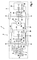
- Fig. 1 is a motor vehicle 1 with a hybrid drive system 2 in a schematic plan view from above to see.
- the body 3 of the motor vehicle 1 is shown only schematically for reasons of clarity.
- the hybrid drive system 2 of the motor vehicle 1 has two axles 4, 5, on each of which wheels 6 are mounted.
- the front axle 4 is driven by an internal combustion engine 7.
- the internal combustion engine 7 has the usual ancillaries, the in Fig. 1 for illustrative reasons are only partially shown.
- Fig. 1 the starter 8 and a generator 9 are shown.
- Starter 8 and generator 9 are connected to the drive shaft 10 of the engine 7, for example via V-belt 11.
- electrical energy is generated with the aid of the generator 9, which can be temporarily stored in an accumulator 12.
- the tensile force generated by the engine 7 is supplied via the drive shaft 10, a clutch 13, a mechanical gear 14, and a differential 15 to the wheels 4 attached to the front axle 4.
- Clutch 13 and manual transmission 14 are in the present case designed as mechanical, manually operated assemblies.
- the motor vehicle driver will disengage the clutch 13 at a certain point in time and shift the manual transmission 14 into the next higher gear. He then engages the clutch 13 by releasing the clutch pedal again. When braking the motor vehicle 1, the motor vehicle driver will shift down the gear of the gearbox 14 accordingly.
- the hybrid drive 2 of the motor vehicle 1 has an electric motor 16.
- the electric motor 16 drives via a Drive shaft 17, a second clutch 18, a second manual transmission 19 and a second differential 32, the wheels 6 of the rear axle 5 at.
- the second clutch 18 and the second gearbox 19 are each automatically actuated by an electronic control circuit 20.
- the electric motor 16 is driven by the electronic control circuit 20.
- the electric motor 16 receives the electrical energy from the accumulator 12 in a drive mode. In a recuperation mode, the electric motor 16 operates as a generator and the electrical energy generated by it is temporarily stored in the accumulator 12.
- the control circuit 20 in addition to the electric motor 16, the second clutch 18 and the second manual transmission 19, for example, can influence the drive power of the engine 7.
- the electronic control circuit 20 is connected via signal lines 21 with a plurality of measuring sensors 29, which are arranged, for example, in the first manual transmission 14, in the first clutch 13, in the internal combustion engine 7 and / or in the generator 9. Further measuring sensors 29 may, for example, also be provided in the electric motor 16 itself, where, for example, they can measure the rotational speed of the electric motor 16. In addition, a measuring sensor 29 is provided which can measure the rotational speed of the wheels 6 and can supply the measuring signal via a control line 21 to the control circuit 20.
- the operating point of the electric motor 16 can be dependent on the rotational speed of the wheels 6 and thus be adjusted depending on the vehicle speed.
- the electronic control 20 selects a low gear, for example, for the second manual transmission 19.
- the electric motor 16 has an increased speed, which results in a high efficiency of the electric motor 16.
- the electronic control 20 selects a high gear for the second manual transmission 19. This avoids over-rotation of the electric motor 16, which could damage the electric motor 16.
- Fig. 2 is a for the operation of in Fig. 1 illustrated, provided with a hybrid drive system 2 motor vehicle 1 suitable circuit diagram 22 is shown.
- the torque of the electric motor 16 is shown.
- the torque of the electric motor 16 may be positive (right side I of the circuit diagram 22). This corresponds to a drive mode of the motor vehicle 1, in which the electric motor 16 drives the motor vehicle 1.
- the electric motor 16 can also be operated with a negative torque (left side II of the circuit diagram 22). This corresponds to a recuperation operation in which the motor vehicle 1 is decelerated.
- a first switching condition results from the maximum speed curve 25. If this speed is reached, an upshift of the second gearbox 19 is always triggered immediately regardless of the other operating conditions. This prevents the possibility of damaging the electric motor 16. In the case of the maximum speed curve 25, the reliability of the hybrid drive 2 dominates the comfort aspect and the profitability aspect. As a rule, this curve 25 is only a safety measure provided, as a rule, an upshift of the second Druckgetiebes 19 before, done by another switching curve.
- a second switching condition is in the form of the upshift curve with active internal combustion engine 26. If the internal combustion engine 7 is running and the operating point of the electric motor 16 is above the upshift curve with the internal combustion engine 26 running, then the second manual transmission 19 is shifted upwards by one gear. Under comfort considerations (the lowest possible shift shock, or the lowest possible shift compensation by the engine 7), the curve should be at the lowest possible torque. Therefore, the upshift curve with active engine 26 is lower at low engine torques than at higher engine torques. At higher electric motor torques, however, due to the then required high load redistribution between the electric motor 16 and the engine 7, the upshift is performed delayed to "hope" for a combustion engine switching (see the following paragraph).
- the gear change of the second gearbox 19 can be performed unobtrusively in this area.
- the gear change takes place at a distance from the maximum speed curve 25.
- the switching condition curve 26 of course also takes into account the efficiency of the electric motor 16 in the respective torque or speed range.
- Another curve is in the form of the upshift curve with the engine running and the engine switch change 27.
- This curve 27 is selected only if, on the one hand, the internal combustion engine 7 is in operation, on the other hand the first clutch 13 (belonging to the internal combustion engine 7) is disengaged. If the operating point of the electric motor 16 is above the upshift curve with the internal combustion engine running and the engine changeover switch 27, the second manual transmission also becomes 19 of the electric motor 16 switched up a gear.
- the upshift curve with active engine and engine shift change 27 is lower than the upshift curve with active engine 26 (without engine switch change).
- the upshift curve with active internal combustion engine 26 is substantially limited dadruch downwards if the maximum possible torque of the electric motor 16 (too much) would be limited by a higher gear. This is dependent on the position of the power hyperbola of the electric motor 16. If the gear is too high, the power hyperbola of the electric motor 16 would be left, ie the range in which the product of rotational speed and torque is constant. At too low speeds, the maximum torque of the electric motor 16, however, is independent of speed.
- the upshift curve with the engine running and the engine switch change 27 is substantially lower than the upshift curve with the internal combustion engine 26.
- the gear change of the second gearbox 19 takes place earlier than compelling due to economic aspects.
- this early gear change makes sense, since the motor vehicle driver expects an interruption of the tensile force at a disengagement of the first clutch 13 anyway. This early upshift thus leads to a subjective comfort gain.
- the upshift curve for switched-off internal combustion engine 28 is relevant. If the operating point of the electric motor 16 is above the upshift curve with the internal combustion engine 28 switched off and the internal combustion engine 7 is switched off, then the second manual transmission 19 is shifted upwards by one gear. As a result, at low torques of the electric motor 16 early switched, but at high torques only much later. Man can also combine this switching condition with a certain time delay, so as to give the engine 7 time to start first, before the second transmission 19 is switched, and thus one of the two upshifts with the internal combustion engine 26, 27 acts pertinent. Because normally, an upshifting of the second gearbox 19 should be triggered with the internal combustion engine 7 only with a small torque of the electric motor 16.
- the shape of the upshift curve for switched-off internal combustion engine 28 can also be selected in practice so that is switched early in a low torque range, but at very high torque only very late or not at all (curve in the form of a very narrow "V").
- the downshift curve with the internal combustion engine 31 is also asymmetrical to the ordinate 24.
- the driver's request For example, by actuating a corresponding button, the driver can suppress the downshifting of torques M of the electric motor 16 with M ⁇ 0. Then, the downshift of the second transmission 19 is suppressed only when the engine 7 can not actually apply the desired torque.
- the downshift curve is relevant when the internal combustion engine 30 is switched off. If the operating point of the electric motor 16 is below the downshift curve when the internal combustion engine 30 is switched off, then during a recuperation operation it is only downshifted when the motor vehicle is at a standstill. At a standstill of the motor vehicle, however, can be switched easily. If the internal combustion engine 7 has received a switch-off signal, then it can also be provided by the controller 20 that first of all a (possibly preferred) downshifting of the second manual transmission 19 takes place, and only then Internal combustion engine 7 is turned off. The switching off of the internal combustion engine 7 is therefore delayed.
- the missing braking torque can be easily applied by the electric motor 16 as a result of a "wrong" gear through conventional vehicle brakes.
Landscapes
- Engineering & Computer Science (AREA)
- Transportation (AREA)
- Mechanical Engineering (AREA)
- Combustion & Propulsion (AREA)
- Chemical & Material Sciences (AREA)
- Power Engineering (AREA)
- Automation & Control Theory (AREA)
- Life Sciences & Earth Sciences (AREA)
- Sustainable Development (AREA)
- Sustainable Energy (AREA)
- Electromagnetism (AREA)
- Physics & Mathematics (AREA)
- Electric Propulsion And Braking For Vehicles (AREA)
- Hybrid Electric Vehicles (AREA)
Description
- Die Erfindung betrifft ein Hybridantriebssystem für ein Kraftfahrzeug mit wenigstens einem Verbrennungsmotor und wenigstens einem Elektromotor, welche jeweils zumindest ein Rad des Kraftfahrzeugs antreiben. Die Erfindung betrifft weiterhin ein Kraftzeug mit einem Hybridantriebssystem.
- Vor dem Hintergrund steigender Rohölpreise sowie dem sich abzeichnenden Wandel des Erdklimas wird die Forderung nach möglichst verbrauchsarmen und treibstoffeffizienten Kraftfahrzeugen zunehmend größer.
- Ein vielversprechender Ansatz hierzu liegt in der Verwendung von Kraftfahrzeugen mit Hybridantriebssystemen. Bei Hybridantriebssystemen wird zusätzlich zum normalen Verbrennungsmotor ein weiterer Motor verwendet, der eine unterschiedliche Energieform nutzt, um das Kraftfahrzeug anzutreiben. In der Praxis haben sich hierzu Elektromotoren durchgesetzt.
- Durch die Verwendung zusätzlicher Motoren ist es einerseits möglich, den Verbrennungsmotor weitgehend dauerhaft in einem besonders energieeffizienten Betriebsmodus zu betreiben. Die vom Verbrennungsmotor gelieferte Antriebsenergie, die zu einem bestimmten Zeitpunkt nicht zum Antrieb des Kraftfahrzeugs genutzt wird, kann in einem Energiespeicher, wie beispielsweise einem Akkumulator, zwischengespeichert werden. Zu einem späteren Zeitpunkt kann die so zwischengespeicherte Energie zum Antrieb des Kraftfahrzeugs genutzt werden. Der Verbrennungsmotor kann dadurch entlastet werden, oder sogar ganz ausgeschaltet werden. Gegebenenfalls ist es auch möglich, den Verbrennungsmotor kleiner zu dimensionieren. Darüber hinaus ist es auch möglich bei einer Verzögerung des Kraftfahrzeugs die kinetische Energie des Kraftfahrzeugs in elektrische Energie umzuwandeln und im Akkumulator zwischenzuspeichern. Die Bremsenergie geht dadurch nicht "verloren".
- Aufgrund dieser (und weiterer) Effekte sind Kraftfahrzeuge mit Hybridantriebssystemen besonders kraftstoffeffizient, insbesondere wenn das Kraftfahrzeug im Stadtverkehr betrieben wird.
- Aufgrund der noch relativ jungen Technologie gibt es noch relativ viele bislang ungelöste Detailprobleme, die eine rasche Verbreitung von Hybridantriebssystemen bislang verhindern.
- Ein Problem besteht beispielsweise bei sogenannten Axle-Split-Hybrid-Antrieben (die Antriebsmotoren wirken auf unterschiedliche Antriebsachsen). Bei diesen wird eine Achse des Kraftfahrzeugs von einem konventionellen Verbrennungsmotor angetrieben. Die Elektromotoren des Hybridantriebs wirken dagegen auf eine zweite Achse. Bei derartigen Axle-Split-Hybrid-Antrieben kann die elektrische Maschine nicht den gesamten Fahrzeuggeschwindigkeitsbereich abdecken: Einerseits ist die maximal mögliche Drehzahl des Elektromotors nach oben hin begrenzt, um Beschädigungen des Elektromotors zu vermeiden. Wird der Elektromotor demgegenüber bei niedrigen Drehzahlen betrieben, so führt dies zu ungünstigen Wirkungsgraden des Elektromotors, was naturgemäß unerwünscht ist. Die Auslegung des Arbeitspunkts des Elektromotors stellt daher einen Kompromiss dar, der an beiden Enden des Geschwindigkeitsbereichs des Kraftfahrzeugs Probleme verursacht.
- Um durch die Drehzahlobergrenze des Elektromotors weniger eingeschränkt zu sein, wurde in
EP 0 224 144 A1 bereits vorgeschlagen, die mechanische Verbindung zwischen Antriebsachse und Elektromotor durch eine Kupplung lösen zu können. Hierdurch kann der Wirkungsgrad des Elektromotors im niedrigen Geschwindigkeitsbereich des Kraftfahrzeugs erhöht werden. Gleichzeitig kann durch Auskuppeln der Kupplung eine Beschädigung des Elektromotors bei hohen Fahrzeuggeschwindigkeiten vermieden werden. - Aus der Offenlegungsschrift
DE 10 2006 046 419 A1 ist außerdem ein Hybridantriebssystem mit einem Verbrennungsmotor bekannt, der über ein Schaltgetriebe einer ersten Achse zugeordnet ist, sowie mit einer Elektromaschine, die einer zweiten Achse zugeordnet und über ein Schaltgetriebe mit dieser verbunden ist. Ein ähnliches Hydbridantriebssystem ist aus derUS 2008/0051248 A1 bekannt, wobei hier auf ein Schaltgetriebe zwischen Elektromotor und der dem Elektromotor zugeordneten Achse verzichtet wird. - Die bislang bekannten Hybridantriebssysteme weisen jedoch nach wie vor Nachteile auf.
- Daher wird gemäß Anspruch 1 vorgeschlagen, bei einem Hybridantriebssystem für ein Kraftfahrzeug, welches wenigstens einen Verbrennungsmotor und wenigstens einen Elektromotor aufweist, welche jeweils zumindest ein Rad des Kraftfahrzeugs antreiben, wobei der wenigstens eine Verbrennungsmotor über ein erstes Mehrganggetriebe mit dem zumindest einen korrespondierenden Rad gekoppelt ist, derart weiterzubilden, dass der zumindest eine Elektromotor über ein zweites Mehrganggetriebe mit dem zumindest einen korrespondierenden Rad gekoppelt ist. Bei stehendem Verbrennungsmotor wird vor einem Schaltvorgang eines zweiten Mehrganggetriebes der Verbrennungsmotor gestartet und/oder bei laufendem Verbrennungsmotor ein Ausschalten des Verbrennungsmotor bis zur Durchführung eines Schaltvorgangs eines zweiten Mehrganggetriebes verzögert. Dadurch ist es auf besonders elegante Weise möglich, unerwünschte Schaltrucke, die durch ein Schalten des zweiten Mehrganggetriebes verursacht werden könnten, zu verringern bzw. zu vermeiden. Durch ein derartiges zweites Mehrganggetriebe ist es möglich, zumindest einen Elektromotor über den gesamten Geschwindigkeitsbereich des Kraftzeugs hinweg im Wesentlichen immer in einem günstigen Arbeitspunkt (also bei höheren Drehzahlen) zu betreiben. Dadurch ist es möglich, dass der zusätzliche Elektromotor im gesamten Geschwindigkeitsbereich des Kraftfahrzeugs auf besonders effektive Weise eine hohe zusätzliche Antriebsleistung bereitstellen kann. Anderseits ist es auch möglich, in einem Rekuperationsbetrieb möglichst viel kinetische Energie in elektrische Energie umzuwandeln und zwischenzuspeichern. Der eingesetzte Kraftstoff kann dadurch besonders effektiv genutzt werden. Es ist im Übrigen auch möglich, dass die vom Verbrennungsmotor angetriebene Achse bereits von einem Hybridantrieb (Parallelhybrid oder Leistungsverzweiger) angetrieben wird. Bei den Mehrganggetrieben kann es sich um beliebige Getriebe handeln, bei denen das Übersetzungsverhältnis geändert werden kann. Insbesondere kann es sich um gestufte Schaltgetriebe, stufenlose Getriebe, automatische Getriebe, manuelle Schaltgetriebe und/oder automatisierte Schaltgetriebe mit manueller Gangvorwahl handeln. Die Mehrganggetriebe (erstes Mehrganggetriebe/zweites Mehrganggetriebe usw.) können selbstverständlich unterschiedlich ausgebildet sein. Die Kopplung kann zu einem Einzelrad hin, oder aber auch zu einer Antriebsachse hin erfolgen. Möglich ist es im Übrigen auch, beispielsweise Differenziale oder dergleichen vorzusehen.
- Erfindungsgemäß ist vorgesehen, dass der wenigstens eine Verbrennungsmotor und der wenigstens eine Elektromotor mit unterschiedlichen Rädern, vorzugsweise mit Rädern unterschiedlicher Achsen gekoppelt ist. Dadurch kann auf besonders einfache Weise eine Art Allradantrieb realisiert werden. Darüber hinaus weist eine derartige Ausbildung auch Vorteile hinsichtlich der Ansteuerung der unterschiedlichen Motoren auf.
- Erfindungsgemäß ist vorgesehen, dass die Mehrganggetriebe als Mehrstufenschaltgetriebe ausgebildet sind. Derartige Schaltgetriebe wurden über die Jahrzehnte hinweg optimiert und sind daher problemlos in vorteilhaften Bauformen verfügbar. Auch sind die in dem Getriebe entstehenden Verluste relativ klein. Bei den Mehrstufenschaltgetriebe kann es sich in beliebiger Weise um Automatikgetriebe, manuelle Schaltgetriebe oder automatisierte Schaltgetriebe mit manueller Gangvonrvahl handeln.
- Möglich ist es, eine Steuerschaltung vorzugehen, welche die Schaltstellung zumindest eines der Mehrganggetriebe und/oder die Ansteuerung des wenigstens einen Verbrennungsmotors und/oder die Ansteuerung des wenigstens einen Elektromotors beeinflusst. Selbstverständlich kann die Beeinflussung durchaus so weit gehen, dass die Steuerung des, beziehungsweise der entsprechenden Komponenten im Wesentlichen vollständig durch die Steuerschaltung erfolgt. Mit Hilfe einer derartigen Steuerschaltung können auf besonders einfache Weise unterschiedliche Regelungsaufgaben übernommen werden. So kann beispielsweise das Hybridantriebssystem auf besonders effizientes und energiesparendes Fahren, auf möglichst komfortables Fahren oder auf eine "Mittelstellung" hin optimiert werden. Insbesondere dann, wenn es sich um ein Kraftfahrzeug mit handbetätigter Schaltung (vollständig manuelles Schaltgetriebe und/oder automatisiertes Schaltgetriebe mit manueller Gangvorwahl) handelt, ist es bevorzugt, wenn die Steuerschaltung insbesondere die Ansteuerung des Elektromotors und/oder die Ansteuerung des zweiten Mehrganggetriebes (welches zum Elektromotor korrespondiert) beeinflusst oder sogar im Wesentlichen bewirkt. Dadurch kann für den Kraftfahrzeugführer ein weitgehend authentisches Fahrverhalten des Kraftfahrzeugs vermittelt werden.
- Möglich ist es darüber hinaus, Messsensoren vorzusehen, welche insbesondere die Schaltstellung zumindest eines der Mehrganggetriebe und/oder den Betriebszustand des wenigstens einen Verbrennungsmotors und/oder den Betriebszustand des wenigstens einen Elektromotors und/oder den Betriebszustand des Kraftfahrzeugs und/oder die Stellung von Bedienelementen des Kraftfahrzeugs misst. Bei Kenntnis entsprechender Parameter ist es nämlich möglich, die Ansteuerung der sonstigen Komponenten, beziehungsweise von Teilen davon, auf besonders effektive Weise erfolgen zu lassen. Unter einer Schaltstellung zumindest eines der Mehrganggetriebe ist insbesondere der jeweils gewählte Gang und/oder die Stellung "eingekuppelt" beziehungsweise "ausgekuppelt" zu verstehen. Unter einem Betriebszustand eines Motors (Verbrennungsmotor/Elektromotor) ist insbesondere an den Leistungsbedarf, die Leistungsfreisetzung, die Drehzahl und die Temperatur des entsprechenden Motors zu denken. Bei dem Betriebszustand des Kraftfahrzeugs ist insbesondere an die Kraftfahrzeuggeschwindigkeit, Lenkradstellungen, Fahrbahnbeschaffenheit, Kühlwassertemperatur, Außentemperatur, sowie Bergauffahrten, beziehungsweise Bergabfahrten zu denken. Bei der Stellung von Bedienelementen des Kraftfahrzeugs ist nicht nur an die Stellung des Fahrpedals, des Bremspedals sowie des Kupplungspedals zu denken. Vielmehr kann auch eine manuelle Gangvorgabe beziehungsweise eine vom Fahrer bestimmte Schaltstrategie vorgewählt werden. Beispielsweise kann es dem Fahrer ermöglicht werden, zwischen einer möglichst sportlichen Schaltstrategie, einer möglichst verbrauchsarmen Schaltstrategie, sowie einer möglichst komfortablen Schaltstrategie zu wählen.
- Es kann sich als sinnvoll erweisen, in der Steuerschaltung zumindest eine Kennlinie, vorzugsweise zumindest ein Kennlinienfeld mit mehreren Kennlinien zu speichern. Mit Hilfe von Kennlinien beziehungsweise Kennlinienfeldern ist es möglich, Bedingungen zu definieren, bei denen beispielsweise bei einem zweiten Mehrganggetriebe (einem Elektromotor zugehörig) ein Schaltvorgang erfolgen soll. Beispielsweise ist es möglich, in Abhängigkeit von einer Raddrehzahl und vom Drehmoment des Elektromotors (oder aber auch in Abhängigkeit vom Drehmomentwunsch des Kraftfahrzeugführers) eine Schaltbedingung zu definieren. Dabei ist es möglich, die Schaltbedingung zum Hochschalten des Mehrganggetriebes unterschiedlich von der Schaltbedingung zum Herunterschalten des Mehrganggetriebes zu wählen. Möglich ist es auch, mehrere Kennlinienfelder zu speichern. Dabei kann jedes Kennlinienfeld für eine bestimmte Schaltstrategie stehen. Beispielsweise kann ein erstes Kennlinienfeld den Kraftstoffverbrauch minimieren, ein zweites Kennlinienfeld den Fahrkomfort optimieren und ein drittes Kennlinienfeld ein sportliches Fahrverhalten schaffen. Auf diese Weise kann das Hybridantriebssystem besonders einfach auf individuelle Fahrerwünsche angepasst werden.
- Vorteilhaft kann es sein, wenn beim Hybridantriebssystem beim Erreichen von Grenzbeanspruchungsbedingungen ein Gangwechsel eines Mehrganggetriebes, insbesondere eines zweiten Mehrganggetriebes erfolgt, um Überbelastungen von Teilen des Hybridantriebssystems zu vermeiden. Werden also zum Beispiel mechanische und/oder elektrische Belastungsgrenzen des Elektromotors erreicht, wird in jedem Fall ein Gangwechsel initiiert. In diesem Fall geht die Betriebssicherheit des Hybridantriebssystems vor Fahrkomfort und/oder Wirtschaftlichkeit. Die Belastungsgrenze muss dabei nicht notwendigerweise eine Zerstörungsgrenze einer Einrichtung darstellen, sondern es kann sich auch um eine Grenze handeln, bei der beispielsweise der Verschleiß stark ansteigt. Ein Beispiel hierfür ist, dass ein Hochschalten des zweiten Mehrganggetriebes veranlasst wird, wenn sich die Drehzahl des Elektromotors einem kritischen Wert nähert.
- Es kann sich als sinnvoll erweisen, wenn ein Gangwechsel eines zweiten Mehrganggetriebes (einen Elektromotor zugehörig) bevorzugt bei einem Gangwechsel eines ersten Mehrganggetriebes (einem Verbrennungsmotor zugehörig) erfolgt. Diese Strategie kann besonders sinnvoll sein, wenn es sich bei dem ersten Mehrganggetriebe um ein manuell betätigtes Schaltgetriebe handelt. Hier erfolgt die Zugkraftunterbrechung der Elektromotorenzugkraft zu einem Zeitpunkt, zu dem der Fahrer ohnehin eine Zugkraftunterbrechung erwartet. Dadurch kommt es für den Kraftfahrzeugführer zu keiner subjektiven Komforteinbuße. Ganz im Gegenteil kann auf diese Weise ein authentisches Fahrgefühl dargestellt werde.
- Möglich ist es auch, dass bei einem Gangwechsel eines zweiten Mehrganggetriebes (einem Elektromotor zugehörig) der Zugkraftverlust zumindest teilweise, bevorzugt im Wesentlichen von wenigstens einem anderen Motor, insbesondere wenigstens einem Verbrennungsmotor ausgeglichen wird. Dies kann beispielsweise dadurch realisiert werden, dass eine Steuerschaltung die vom Verbrennungsmotor geforderte Leistung korrespondierend zum Zugkraftverlust des Elektromotors hoch reguliert. Dadurch kann der Komfortverlust durch den "Schaltruck" des zweiten Mehrganggetriebes gemindert werden, beziehungsweise im Wesentlichen unterdrückt werden. Auf diese Weise kann das Hybridantriebssystem besonders hohen Komfortansprüchen gerecht werden. Insbesondere ist es möglich, dass der Verbrennungsmotor während des Schaltvorgangs des zweiten Mehrganggetriebes den Zugkraftverlust durch "Wegfallen" des Elektromotors zumindest zum Teil ausgleichen kann. Aber selbst wenn der Verbrennungsmotor während eines solchen "Schaltrucks" nicht (vollständig) nachreguliert wird, so verbleibt dennoch eine gewisse Zugkraft (nämlich die - ggf. erhöhte - Verbrennungsmotorenzugkraft), so dass der Schaltruck für die Fahrzeuginsassen (subjektiv geringer) ausfallen kann.
- Sinnvoll ist es darüber hinaus, wenn ein Gangwechsel eines zweiten Mehrganggetriebes in einem Drehmomentbereich des Elektromotors erfolgt, in dem der Zugkraftverlust weitgehend, bevorzugt im Wesentlichen vollständig von wenigstens einem anderen Motor, insbesondere von wenigstens einem der Verbrennungsmotoren ausgeglichen werden kann. Unter dem Begriff "weitgehend" ist dabei an einen Zugkraftausgleich von beispielsweise 85%, 90%, 95%, 98%, 99% oder 100% zu denken. "Droht" durch die Betriebsbedingungen, dass ein derartiger Drehmomentbereich verlassen wird, so wird beispielsweise vorab ein Schaltvorgang des zweiten Mehrganggetriebes initiiert. Dadurch kann eine möglichst weitgehende Zugkraftkompensation für einen Großteil von Betriebszuständen des Hybridantriebssystems realisiert werden.
- Möglich ist es weiterhin, dass bei wenigstens einem laufenden Verbrennungsmotor ein Gangwechsel eines zweiten Mehrganggetriebes bei möglichst niedrigen Drehmomenten des Elektromotors erfolgt, wobei als Untergrenze bevorzugt der Wirkungsgrad des Elektromotors und/oder die Leis tungshyperbel zumindest eines Elektromotors dient. Kleine Drehmomente des Elektromotors haben üblicherweise den Vorteil, dass der spürbare Schaltruck besonders gering ist, bzw. vom Verbrennungsmotor nur besonders kleine Zugkraftunterbrechungen kompensiert werden müssen. Eine Untergrenze für einen Hochschaltvorgang ist sinnvollerweise durch die Wirkungsgradkurve des Elektromotors gegeben. Fällt der Wirkungsgrad des Elektromotors ab, so überwiegt ab einem gewissen Punkt der Wirtschaftlichkeitsäspekt vor dem Komfortaspekt. Eine andere Untergrenze kann sich durch die Leistungshyperbel des Elektromotors ergeben. Oberhalb der Leistungshyperbel ist das Produkt aus Drehzahl und Drehmoment konstant. Bei kleinerer Drehzahl ist dagegen das maximale Drehmoment von der Drehzahl unabhängig und konstant. Der Schaltvorgang kann dabei sinnvollerweise so gelegt werden, dass sich nach dem Hochschaltvorgang noch ein maximales Drehmoment des Elektromotors ergeben kann. Es ist auch möglich, dass die Untergrenze von anderen Parametern, wie beispielsweise der Drehzahl des Elektromotors, dem geforderten Drehmoment des Elektromotors und/oder davon, ob das Mehrstufengetriebe des Verbrennungsmotors geschaltet wird, abhängig ist. So kann beispielsweise bei eingekuppeltem Verbrennungsmotor die Schaltgrenze über den Wirkungsgrad definiert werden, wohingegen bei einem Gangwechsel des Verbrennungsmotor der Schaltvorgang des zweiten Mehrganggetriebes durch die Leistungshyperbel definiert wird, was in der Regel einen Schaltvorgang bei niedrigeren Drehzahlen und/oder Drehmomenten bewirkt. Es ist im Übrigen auch möglich, die Gewichtungen (oder einen Teil davon) in Abhängigkeit von einem Fahrerwunsch vorzunehmen.
- Eine weitere bevorzugte Ausbildung des Hybridantriebssystem kann sich ergeben, wenn bei wenigstens einem stehenden Verbrennungsmotor ein Gangwechsel eines zweiten Mehrganggetriebes bei möglichst niedrigen Drehmomenten des Elektromotors erfolgt. Hier ist der spürbare Schaltruck um so kleiner, je kleiner das Drehmoment des Elektromotors ist. Die Kurve kann auch so gewählt werden, dass bei höheren Drehmomenten zunächst gar nicht geschaltet wird, und beispielsweise zunächst abgewartet wird, bis zumindest ein Verbrennungsmotor gestartet wurde. Eine untere Grenze kann hier jedoch auch beispielsweise durch die Leistungshyperbel oder die Wirkungsgradkurve des Elektromotors vorgegeben werden, wobei hier ggf. noch ein Korrekturfaktor (insbesondere im Verhältnis zur Schaltbedingung bei laufendem Verbrennungsmotor) verwendet werden kann.
- Weiterhin ist es möglich, dass ein Herunterschalten eines zweiten Mehrganggetriebes (einem Elektromotor zugehörig) bei einer Verzögerung des Kraftfahrzeugs und/oder bei einem Rekuperationsbetrieb verzögert und/oder vermieden wird, insbesondere in einem hohen Drehmomentbereich des Elektromotors, speziell bei wenigstens einem stehenden Verbrennungsmotor. Gerade bei einem Leerlaufbetrieb des Verbrennungsmotors beziehungsweise bei stehendem Verbrennungsmotor ist es nur schwer möglich oder praktisch unmöglich die Unterbrechung der Verzögerungsleistung des Elektromotors aufgrund des "Schaltrucks" mit Hilfe des Verbrennungsmotors auszugleichen. Wird hier ein Herunterschalten des zweiten Mehrganggetriebes verzögert beziehungsweise sogar ganz vermieden, so wird zwar weniger Bremsenergie in elektrische Energie zurückgewonnen, jedoch kann der Fahrkomfort beträchtlich erhöht werden. Der Gewinn an Fahrkomfort kann den vergleichsweise geringen Nachteil eines relativ geringen Energieverlusts mehr als aufwiegen. Naturgemäß fällt der (nicht ausgeglichene) Schaltruck des zweiten Mehrganggetriebes umso größer aus, je größer das Drehmoment des Elektromotors ist.
- Weiterhin wird vorgeschlagen, ein Kraftfahrzeug mit einem Hybridantriebssystem zu versehen, welches die oben beschriebenen Eigenschaften aufweist. Das Kraftfahrzeug weist dann die bereits beschriebenen Eigenschaften und Vorteile in analoger Weise auf.
- Weiterhin wird ein Verfahren beansprucht, bei dem das oben beschriebene Hybridantriebssystem eines Kraftfahrzeugs auf oben beschriebene Weise geschaltet wird.
- Im Folgenden wird die Erfindung an Hand möglicher Ausführungsformen und unter Bezugnahme auf die beiliegenden Figuren näher erläutert. Es zeigen:
- Fig. 1:
- Ein Ausführungsbeispiel für ein Hybridantriebssystem in schematischer Draufsicht;
- Fig. 2:
- ein Ausführungsbeispiel für ein Kennlinienfeld.
- In
Fig. 1 ist ein Kraftfahrzeug 1 mit einem Hybridantriebssystem 2 in schematischer Draufsicht von oben zu sehen. Die Karosserie 3 des Kraftfahrzeugs 1 ist aus Übersichtsgründen nur schematisch dargestellt. Das Hybridantriebssystem 2 des Kraftfahrzeugs 1 verfügt über zwei Achsen 4, 5, an denen jeweils Räder 6 montiert sind. - Die Vorderachse 4 wird von einem Verbrennungsmotor 7 angetrieben. Der Verbrennungsmotor 7 verfügt über die üblichen Nebenaggregate, die in
Fig. 1 aus zeichnerischen Gründen nur teilweise dargestellt sind. InFig. 1 sind der Anlasser 8 und ein Generator 9 dargestellt. Anlasser 8 und Generator 9 sind mit der Antriebswelle 10 des Verbrennungsmotors 7 beispielsweise über Keilriemen 11 verbunden. In Betriebszuständen des Kraftfahrzeugs 1, bei denen die vom Verbrennungsmotor 7 erzeugte Leistung nicht vollständig zum Antrieb des Kraftfahrzeugs 1 benötigt wird, wird mit Hilfe des Generators 9 elektrische Energie erzeugt, die in einem Akkumulator 12 zwischengespeichert werden kann. - Die vom Verbrennungsmotor 7 erzeugte Zugkraft wird über die Antriebswelle 10, eine Kupplung 13, ein mechanischens Schaltgetriebe 14, und ein Differenzial 15 den an der Vorderachse 4 befestigten Rädern 6 zugeführt. Kupplung 13 und Schaltgetriebe 14 sind vorliegend als mechanische, manuell bediente Baugruppen ausgeführt.
- Steigt mit zunehmender Geschwindigkeit des Kraftfahrzeugs 1 die Drehzahl des Verbrennungsmotors 7 an, so wird der Kraftfahrzeugführer zu einem gewissen Zeitpunkt die Kupplung 13 ausrücken und das Schaltgetriebe 14 in den nächsthöheren Gang schalten. Anschließend rückt er die Kupplung 13 durch Lösen des Kupplungspedals wieder ein. Bei einem Abbremsen des Kraftfahrzeugs 1 wird der Kraftfahrzeugführer den Gang des Schaltgetriebes 14 dementsprechend herunter schalten.
- Zusätzlich zum Verbrennungsmotor 7 verfügt der Hybridantrieb 2 des Kraftfahrzeugs 1 über einen Elektromotor 16. Der Elektromotor 16 treibt über eine Antriebswelle 17, eine zweite Kupplung 18, ein zweites Schaltgetriebe 19 und ein zweites Differenzial 32 die Räder 6 der Hinterachse 5 an. Die zweite Kupplung 18 und das zweite Schaltgetriebe 19 werden jeweils automatisch von einer elektronischen Steuerschaltung 20 betätigt. Auch der Elektromotor 16 wird von der elektronischen Steuerschaltung 20 angesteuert. Der Elektromotor 16 bezieht in einem Antriebsmodus die elektrische Energie vom Akkumulator 12. In einem Rekuperationsmodus arbeitet der Elektromotor 16 als Generator und die von ihm erzeugte elektrische Energie wird im Akkumulator 12 zwischengespeichert. Im Übrigen ist es auch möglich, dass die Steuerschaltung 20 neben dem Elektromotor 16, der zweiten Kupplung 18 und dem zweiten Schaltgetriebe 19 beispielsweise auch die Antriebsleistung des Verbrennungsmotors 7 beeinflussen kann.
- Die elektronische Steuerschaltung 20 ist über Signalleitungen 21 mit mehreren Messsensoren 29 verbunden, die beispielsweise im ersten Schaltgetriebe 14, in der ersten Kupplung 13, im Verbrennungsmotor 7 und/oder im Generator 9 angeordnet sind. Weitere Messsensoren 29 können beispielsweise auch im Elektromotor 16 selbst vorgesehen sein, wo sie beispielsweise die Drehzahl des Elektromotors 16 messen können. Darüber hinaus ist ein Messsensor 29 vorgesehen, der die Drehzahl der Räder 6 messen kann und das Messsignal über eine Steuerleitung 21 der Steuerschaltung 20 zuführen kann.
- Dadurch dass die vom Elektromotor 16 freigesetzte Antriebsenergie (beziehungsweise in einem Rekuperationsmodus des Kraftfahrzeugs 1 die mechanische Verzögerungsleistung) über eine zweite Kupplung 18 und eine zweites Schaltgetriebe 19 den an der Hinterachse 5 befestigten Rädern 6 zugeführt wird, kann der Arbeitspunkt des Elektromotors 16 in Abhängigkeit von der Drehgeschwindigkeit der Räder 6 und damit in Abhängigkeit von der Fahrzeuggeschwindigkeit angepasst werden. Bei einer niedrigen Geschwindigkeit des Kraftfahrzeugs 1 wählt die elektronische Steuerung 20 beispielsweise für das zweite Schaltgetriebe 19 einen niedrigen Gang. Dadurch weist der Elektromotor 16 eine erhöhte Drehzahl auf, was in einem hohen Wirkungsgrad des Elektromotors 16 resultiert. Bei einer hohen Geschwindigkeit des Kraftfahrzeugs 1 wählt die elektronische Steuerung 20 dagegen einen hohen Gang für das zweite Schaltgetriebe 19. Dadurch wird ein Überdrehen des Elektromotors 16 vermieden, welches den Elektromotor 16 beschädigen könnte.
- In
Fig. 2 ist ein für den Betrieb des inFig. 1 dargestellten, mit einem Hybridantriebssystem 2 versehenen Kraftfahrzeugs 1 geeignetes Schaltschema 22 dargestellt. Auf der Abszisse 23 ist das Drehmoment des Elektromotors 16 dargestellt. Das Drehmoment des Elektromotors 16 kann positiv sein (rechte Seite I des Schaltschemas 22). Dies entspricht einem Antriebsmodus des Kraftfahrzeugs 1, bei dem der Elektromotor 16 das Kraftfahrzeug 1 antreibt. Der Elektromotor 16 kann jedoch auch mit einem negativem Drehmoment betrieben werden (linke Seite II des Schaltschemas 22). Dies entspricht einem Rekuperationsbetrieb, bei dem das Kraftfahrzeug 1 verzögert wird. - Auf der Ordinate 24 des Schaltschemas 22 ist die Drehzahl der Räder 6 dargestellt. Diese korrespondiert unter üblichen Betriebsbedingungen mit der Geschwindigkeit des Kraftfahrzeugs 1.
- Eine erste Schaltbedingung ergibt sich durch die Höchstdrehzahlkurve 25. Wird diese Drehzahl erreicht, wird unabhängig von den sonstigen Betriebsbedingungen immer sofort eine Hochschaltung des zweiten Schaltgetriebes 19 ausgelöst. Dadurch wird verhindert dass es zu einer Beschädigung des Elektromotors 16 kommen kann. Im Falle der Höchstdrehzahlkurve 25 dominiert die Betriebssicherheit des Hybridantriebs 2 den Komfortaspekt und den Wirtschaftlichkeitsaspekt. In der Regel ist diese Kurve 25 nur als Sicherheitsmaßnahme vorgesehen, da in der Regel eine Hochschaltung des zweiten Schaltgetiebes 19 schon vorher, durch eine andere Schaltkurve erfolgt.
- Eine zweite Schaltbedingung liegt in Form der Hochschaltkurve bei aktivem Verbrennungsmotor 26 vor. Sofern der Verbrennungsmotor 7 läuft und der Arbeitspunkt des Elektromotors 16 oberhalb der Hochschaltkurve bei laufendem Verbrennungsmotor 26 liegt, so wird das zweite Schaltgetriebe 19 um einen Gang nach oben geschaltet. Unter Komforterwägungen (möglichst niedriger Schaltruck, bzw. möglichst geringer Schaltruckausgleich durch den Verbrennungsmotor 7) sollte die Kurve bei möglichst niedrigen Drehmomenten liegen. Daher liegt die Hochschaltkurve bei aktivem Verbrennungsmotor 26 bei niedrigen Elektromotor-Drehmomenten niedriger als bei höheren Elektromotor-Drehmomenten. Bei höheren Elektromotor-Drehmomenten wird dagegen aufgrund der dann erforderlichen hohen Lastumverteilung zwischen Elektromotor 16 und Verbrennungsmotor 7 das Hochschalten verzögert durchgeführt, um auf einen Verbrennungmotorschaltwechsel (siehe folgender Absatz) zu "hoffen". Dennoch kann der Gangwechsel des zweiten Schaltgetriebes 19 auch in diesem Bereich unauffällig durchgeführt werden. In jedem Fall erfolgt der Gangwechsel mit einem Abstand zur Höchstdrehzahlkurve 25. Die Schaltbedingungskurve 26 berücksichtigt selbstverständlich auch den Wirkungsgrad des Elektromotors 16 im jeweiligen Drehmoment- bzw. Drehzahlbereich.
- Eine weitere Kurve liegt in Form der Hochschaltkurve bei laufendem Verbrennungsmotor und Verbrennungsmotorschaltwechsel 27 vor. Diese Kurve 27 wird nur dann gewählt, wenn einerseits der Verbrennungsmotor 7 in Betrieb ist, anderseits die erste Kupplung 13 (dem Verbrennungsmotor 7 zugehörig) ausgerückt wird. Liegt der Arbeitspunkt des Elektromotors 16 oberhalb der Hochschaltkurve bei laufendem Verbrennungsmotor und Verbrennungsmotorschaltwechsel 27 so wird auch das zweite Schaltgetriebe 19 des Elektromotors 16 einen Gang hoch geschaltet. Im vorliegenden Schaltungsmodell 22 liegt die Hochschaltkurve bei aktivem Verbrennungsmotor und Verbrennungsmotorschaltwechsel 27 niedriger als die Hochschaltkurve bei aktivem Verbrennungsmotor 26 (ohne Verbrennungsmotorschaltwechsel). Die Hochschaltkurve bei aktivem Verbrennungsmotor 26 wird nach unten im Wesentlichen dadruch begrenzt, wenn durch einen höheren Gang das maximal mögliche Drehmoment des Elektromotors 16 (zu stark) begrenzt würde. Dies ist abhängig von der Lage der Leistungshyperbel des Elektromotors 16. In einem zu hohen Gang würde die Leistungshyperbel des Elektromotors 16 verlassen werden, also der Bereich, in dem das Produkt aus Drehzahl und Drehmoment konstant sind. Bei zu niedrigen Drehzahlen ist das maximale Drehmoment des Elektromotors 16 dagegen Drehzahlunabhängig.
- Die Hochschaltkurve bei laufendem Verbrennungsmotor und Verbrennungsmotorschaltwechsel 27 liegt im Wesentlichen niedriger als die Hochschaltkurve bei laufendem Verbrennungsmotor 26. Im Falle einer ausgerückten ersten Kupplung 13 erfolgt somit der Gangwechsel des zweiten Schaltgetriebes 19 früher als unter Wirtschaftlichkeitsaspekten zwingend. Dieser frühzeitige Gangwechsel ist jedoch sinnvoll, da der Kraftfahrzeugführer bei einem Ausrücken der ersten Kupplung 13 ohnehin eine Unterbrechung der Zugkraft erwartet. Dieses frühzeitige Hochschalten führt somit zu einem subjektiven Komfortgewinn.
- Bei deaktiviertem Verbrennungsmotor 7 ist die Hochschaltkurve für ausgeschalteten Verbrennungsmotor 28 einschlägig. Liegt der Arbeitspunkt des Elektromotors 16 oberhalb der Hochschaltkurve bei ausgeschaltetem Verbrennungsmotor 28 und ist der Verbrennungsmotor 7 abgeschaltet, so wird das zweite Schaltgetriebe 19 um einen Gang nach oben geschaltet. Dadurch wird bei kleinen Drehmomenten des Elektromotors 16 schon früh geschaltet, bei hohen Drehmomenten jedoch erst deutlich später. Mann kann diese Schaltbedingung zusätzlich auch mit einer gewissen Zeitverzögerung kombinieren, um damit den Verbrennungsmotor 7 Zeit zu geben, zunächst zu starten, bevor das zweite Schaltgetriebe 19 geschaltet wird, und damit eine der beiden Hochschaltkurven bei eingeschaltetem Verbrennungsmotor 26, 27 einschlägig wirkt. Denn normalerweise sollte ein Hochschalten des zweiten Schaltgetriebes 19 bei ausgeschaltetem Verbrennungsmotor 7 nur bei kleinem Drehmoment des Elektromotors 16 ausgelöst werden. Bei großem Drehmoment des Elektromotors 16 ist es sinnvoller, dass der Verbrennungsmotor 7 zunächst in den aktiven Zustand wechselt und der Schaltvorgang dann über die Hochschaltkurve bei laufendem Verbrennungsmotor 26 ausgelöst wird. Die Form der Hochschaltkurve für ausgeschalteten Verbrennungsmotor 28 kann in der Praxis auch so gewählt werden, dass in einem niedrigen Drehmomentbereich schon früh geschaltet wird, bei etwas größeren Drehmomenten jedoch erst sehr spät oder überhaupt nicht (Kurve in Form eines sehr engen "V").
- Bei einem Abbremsen des Kraftfahrzeugs 1 kann prinzipiell auch mit einem höheren Gang des zweiten Schaltgetriebes 19 (beispielsweise mit dem zweiten Gang) bis zum Stillstand des Kraftfahrzeugs 1 gefahren werden. Allerdings ist dann der Wirkungsgrad des Hybridantriebs 2 (und ein gegebenenfalls erforderliches Wiederbeschleunigen des Kraftfahrzeugs 1) eingeschränkt.
- Aus diesem Grund ist es sinnvoller, auch bei einer Verzögerung des Kraftfahrzeugs 1 ein Herunterschalten des zweiten Schaltgetriebes 19 auszulösen. Zur Erhöhung des Komfortgewinns kann dabei zwischen einer Herunterschaltkurve bei laufendem Verbrennungsmotor 31 und eine Herunterschaltkurve bei ausgeschaltetem Verbrennungsmotor 30 unterschieden werden.
- Bei laufendem Verbrennungsmotor wird ein Herunterschalten des zweiten Schaltgetriebes 19 ausgelöst, wenn der Arbeitspunkt des Elektromotors 16 unterhalb der Herunterschaltkurve bei eingeschaltetem Verbrennungsmotor 31 liegt. Bei positivem Drehmoment des Elektromotors 16 kann der Verbrennungsmotor 7 dieses Drehmoment während des Schaltvorgangs zweiten Schaltgetriebes 19 übernehmen. Bei negativem Drehmoment des Elektromotors 16 (Rekuperationsbetrieb) kann dieses Drehmoment dagegen nicht vom Verbrennungsmotor 7 kompensiert werden, und es wird daher mit dem Herunterschalten bis zur Geschwindigkeit 0 gewartet. Aus diesem Grund ist die Herunterschaltkurve bei eingeschaltetem Verbrennungsmotor 31 auch asymmetrisch zur Ordinate 24. Für die Schaltbedingung der Herunterschaltkurve bei laufendem Verbrennungsmotor 31 kann als zusätzliches Kriterium auch der Fahrerwunsch berücksichtig werden. So kann der Fahrer beispielsweise durch Betätigung eines entsprechenden Knopfes das Herunterschalten für Drehmomente M des Elektromotors 16 mit M≤0 unterdrücken. Dann wird das Herunterschalten des zweiten Schaltgetriebes 19 nur dann unterdrückt, wenn der Verbrennungsmotor 7 das gewünschte Drehmoment tatsächlich nicht aufbringen kann.
- Bei ausgeschaltetem Verbrennungsmotor ist die Herunterschaltkurve bei ausgeschaltetem Verbrennungsmotor 30 einschlägig. Liegt der Betriebspunkt des Elektromotors 16 unter der Herunterschaltkurve bei ausgeschaltetem Verbrennungsmotor 30, so wird bei einem Rekuperationsbetrieb erst bei einem Stillstand des Kraftfahrzeugs heruntergeschaltet. Bei einem Stillstand des Kraftfahrzeugs kann jedoch problemlos geschaltet werden. Hat der Verbrennungsmotor 7 ein Ausschaltsignal erhalten, so kann auch durch die Steuerung 20 vorgesehen werden, dass zunächst ein (ggf. vorgezogenes) Herunterschalten des zweiten Schaltgetriebes 19 erfolgt, und erst dann der Verbrennungsmotor 7 ausgeschaltet wird. Der Ausschalten des Verbrennungsmotors 7 wird also verzögert.
- Sowohl bei der Herunterschaltkurve bei eingeschaltetem Verbrennungsmotor 31, als auch bei der Herunterschaltkurve bei ausgeschaltetem Verbrennungsmotor 30 kann das fehlende Bremsmoment durch den Elektromotor 16 infolge eines "falschen" Gangs problemlos durch übliche Fahrzeugbremsen aufgebracht werden.
- In
Fig. 2 wurde aus Übersichtlickeitsgründen lediglich ein Schaltschema 22 für ein zweites Schaltgetriebe 19 dargestellt, das nur zwei Gängen aufweist. Eine Erweiterung auf ein zweites Schaltgetriebe 19 mit drei oder sogar mehr Gängen ist jedoch ohne weiteres möglich.
Claims (11)
- Hybridantriebssystem (2) für ein Kraftfahrzeug (1), aufweisend wenigstens einen Verbrennungsmotor (7) und wenigstens einen Elektromotor (16), welche jeweils zumindest ein Rad (6) des Kraftfahrzeugs (1) antreiben, wobei der wenigstens eine Verbrennungsmotor (7) über ein erstes Mehrganggetriebe (14) mit dem zumindest einen korrespondierenden Rad (6) einer Achse (4) gekoppelt ist, wobei der zumindest eine Elektromotor (16) über ein zweites Mehrganggetriebe (19) mit dem zumindest einen korrespondierenden Rad (6) einer anderen Achse (5) gekoppelt ist, und wobei die Mehrganggetriebe (14,19) als Mehrstufenschaltgetriebe (14,19) ausgebildet sind, dadurch gekennzeichnet, dass bei stehendem Verbrennungsmotor (7) vor einem Schaltvorgang des zweiten Mehrganggetriebes (19) der Verbrennungsmotor (7) gestartet wird und/oder bei laufendem Verbrennungsmotor (7) ein Ausschalten des Verbrennungsmotors (7) bis zur Durchführung eines Schaltvorgangs des zweiten Mehrganggetriebes (19) verzögert wird.
- Hybridantriebssystem (2) nach einem der vorangehenden Ansprüche, dadurch gekennzeichnet, dass eine Steuerschaltung (20) vorgesehen ist, welche die Schaltstellung zumindest eines der Mehrganggetriebe (14, 19) und/oder die Ansteuerung des wenigstens einen Verbrennungsmotors (7) und/oder die Ansteuerung des wenigstens einen Elektromotors (16) beeinflusst.
- Hybridantriebssystem (2) nach einem der vorangehenden Ansprüche, gekennzeichnet durch Messsensoren (29), welche insbesondere die Schaltstellung zumindest eines der Mehrganggetriebe (14, 19) und/oder den Betriebszustand des wenigstens einen Verbrennungsmotors (7) und/oder den Betriebszustand des wenigstens einen Elektromotors (16) und/oder den Betriebszustand des Kraftfahrzeugs (1) und/oder die Stellung von Bedienelementen des Kraftfahrzeugs (1) misst.
- Hybridantriebssystem (2) nach einem der vorangehenden Ansprüche, dadurch gekennzeichnet, dass in der Steuerschaltung (20) zumindest eine Kennlinie, vorzugsweise zumindest ein Kennlinienfeld (22) mit mehreren Kennlinien (25, 26, 27, 28, 30, 31) gespeichert ist.
- Hybridantriebssystem (2) nach einem der vorangehenden Ansprüche, dadurch gekennzeichnet, dass beim Erreichen von Grenzbeanspruchungsbedingungen ein Gangwechsel eines Mehrganggetriebes, insbesondere eines zweiten Mehrganggetriebes (19) erfolgt (25), um Überbelastungen von Teilen des Hybridantriebssystems (2) zu vermeiden.
- Hybridantriebssystem (2) nach einem der vorangehenden Ansprüche, dadurch gekennzeichnet, dass ein Gangwechsel des zweiten Mehrganggetriebes (19) bevorzugt bei einem Gangwechsel des ersten Mehrganggetriebes (14) erfolgt (27).
- Hybridantriebssystem (2) nach einem der vorangehenden Ansprüche, dadurch gekennzeichnet, dass bei einem Gangwechsel des zweiten Mehrganggetriebes (19) der Zugkraftverlust zumindest teilweise, bevorzugt. im Wesentlichen von dem wenigstens einen Verbrennungsmotor (7) ausgeglichen wird.
- Hybridantriebssystem (2) nach einem der vorangehenden Ansprüche, dadurch gekennzeichnet, dass ein Gangwechsel des zweiten Mehrganggetriebes (19) in einem Drehmomentbereich des Elektromotors (16) erfolgt, in dem der Zugkraftverlust weitgehend, bevorzugt im Wesentlichen vollständig von dem wenigstens einen Verbrennungsmotor (7) ausgeglichen werden kann.
- Hybridantriebssystem (2) nach einem der vorangehenden Ansprüche, dadurch gekennzeichnet, dass bei wenigstens einem laufenden Verbrennungsmotor (7) ein Gangwechsel des zweiten Mehrganggetriebes (19) bei möglichst niedrigen Drehmomenten des Elektromotors (16) erfolgt, wobei als Untergrenze bevorzugt der Wirkungsgrad eines Elektromotors (16) und/oder die Leistungshyperbel zumindest eines Elektromotors (16) dient.
- Hybridantriebssystem (2) nach einem der vorangehenden Ansprüche, dadurch gekennzeichnet, dass ein Herunterschalten des zweiten Mehrganggetriebes (19) bei einer Verzögerung des Kraftfahrzeugs (1) und/oder bei einem Rekuperationsbetrieb verzögert und/oder vermieden wird (30, 31), insbesondere in einem hohen Drehmomentbereich des Elektromotors (16).
- Kraftfahrzeug, gekennzeichnet durch ein Hybridantriebssystem nach einem der Ansprüche 1 bis 10.
Applications Claiming Priority (2)
| Application Number | Priority Date | Filing Date | Title |
|---|---|---|---|
| DE102008041985A DE102008041985A1 (de) | 2008-09-11 | 2008-09-11 | Hybridantriebssystem |
| PCT/EP2009/060488 WO2010028925A1 (de) | 2008-09-11 | 2009-08-13 | Hybridantriebssystem |
Publications (2)
| Publication Number | Publication Date |
|---|---|
| EP2321136A1 EP2321136A1 (de) | 2011-05-18 |
| EP2321136B1 true EP2321136B1 (de) | 2014-11-05 |
Family
ID=41129084
Family Applications (1)
| Application Number | Title | Priority Date | Filing Date |
|---|---|---|---|
| EP09781796.9A Not-in-force EP2321136B1 (de) | 2008-09-11 | 2009-08-13 | Hybridantriebssystem |
Country Status (5)
| Country | Link |
|---|---|
| US (1) | US9932030B2 (de) |
| EP (1) | EP2321136B1 (de) |
| CN (1) | CN102149558B (de) |
| DE (1) | DE102008041985A1 (de) |
| WO (1) | WO2010028925A1 (de) |
Families Citing this family (17)
| Publication number | Priority date | Publication date | Assignee | Title |
|---|---|---|---|---|
| DE102008043849A1 (de) | 2008-11-19 | 2010-05-20 | Zf Friedrichshafen Ag | Mehrachsiges Hybrid-Antriebssystem für ein Fahrzeug |
| DE102010036321B4 (de) | 2010-07-09 | 2024-09-12 | Dr. Ing. H.C. F. Porsche Aktiengesellschaft | Antriebssystem für ein Hybridfahrzeug und Hybridfahrzeug mit einem derartigen Antriebssystem |
| DE102010062227A1 (de) * | 2010-11-30 | 2012-05-31 | Robert Bosch Gmbh | Elektrofahrzeug und Verfahren zum Antreiben eines Elektrofahrzeugs |
| JP5660227B2 (ja) * | 2011-10-27 | 2015-01-28 | トヨタ自動車株式会社 | 車両制御システム及び制御装置 |
| CN102582411A (zh) * | 2012-03-06 | 2012-07-18 | 浙江吉利汽车研究院有限公司 | 混合动力驱动系统及相应的混合动力驱动方法 |
| GB2509740A (en) * | 2013-01-11 | 2014-07-16 | Dearman Engine Company Ltd | Cryogenic engine combined with a power generator |
| ITTO20130096A1 (it) * | 2013-02-06 | 2014-08-07 | Oerlikon Graziano Spa | Sistema di propulsione integrale per veicolo a due o piu' assali |
| DE102013210013A1 (de) * | 2013-05-29 | 2014-12-04 | Schaeffler Technologies Gmbh & Co. Kg | Verfahren zum Schalten eines Antriebsstrang für ein Fahrzeug sowie Antriebsstrang |
| FR3023218B1 (fr) * | 2014-07-04 | 2016-08-05 | Peugeot Citroen Automobiles Sa | Procede de commande de systeme de motorisation hybride, pour un vehicule hybride |
| FR3026707B1 (fr) * | 2014-10-06 | 2016-11-04 | Renault Sa | Procede de determination du mode cinematique d'une transmission hybride |
| CN106143206B (zh) * | 2015-03-25 | 2018-12-21 | 比亚迪股份有限公司 | 用于车辆的动力传动系统及其换挡控制方法 |
| DE102016114743A1 (de) * | 2016-08-09 | 2018-02-15 | Volkswagen Aktiengesellschaft | Verfahren zum Betreiben eines hybriden Antriebssystems und Kraftfahrzeug mit hybridem Antriebssystem |
| DE102016216356B4 (de) | 2016-08-30 | 2020-08-06 | Bayerische Motoren Werke Aktiengesellschaft | Verfahren zur Ansteuerung eines Fahrzeugantriebs für ein Kraftfahrzeug sowie Fahrzeugantrieb |
| DE102016225421A1 (de) * | 2016-12-19 | 2018-07-05 | Volkswagen Aktiengesellschaft | Steuerung für ein Kraftfahrzeug, Kraftfahrzeug und Verfahren zur Steuerung eines Kraftfahrzeugs |
| JP6855986B2 (ja) * | 2017-09-04 | 2021-04-07 | トヨタ自動車株式会社 | ハイブリッド車両の駆動力制御装置 |
| DE102018203844A1 (de) * | 2018-03-14 | 2019-09-19 | Zf Friedrichshafen Ag | Verfahren und Steuergerät zum Betreiben eines Hybrid-Antriebsstrangs |
| DE102019205231A1 (de) | 2019-04-11 | 2020-10-15 | Zf Friedrichshafen Ag | Fahrantriebssystem für Arbeitsmaschine |
Family Cites Families (25)
| Publication number | Priority date | Publication date | Assignee | Title |
|---|---|---|---|---|
| US3352373A (en) * | 1963-12-11 | 1967-11-14 | Gen Motors Corp | Vehicles with plural axles and means to provide maximum tractive effort for each axle at the same speed |
| DE3542059C1 (de) | 1985-11-28 | 1987-06-04 | Opel Adam Ag | Kraftfahrzeug mit Hauptantriebsachse und zuschaltbarer Antriebsachse |
| DE4217668C1 (de) * | 1992-05-28 | 1993-05-06 | Daimler Benz Ag | Verfahren zur Steuerung eines ein Fahrzeug antreibenden Hybridantriebes |
| US6847189B2 (en) * | 1995-05-31 | 2005-01-25 | The Regents Of The University Of California | Method for controlling the operating characteristics of a hybrid electric vehicle |
| DE19623847A1 (de) | 1995-06-16 | 1996-12-19 | Aisin Aw Co | Steuerungssystem für eine Fahrzeugantriebseinheit |
| CN1071645C (zh) | 1996-05-30 | 2001-09-26 | 杨泰和 | 分配式差动混合复合动力系统 |
| DE19810374B4 (de) * | 1998-03-10 | 2013-05-02 | Bayerische Motoren Werke Aktiengesellschaft | Hybridantrieb für ein Kraftfahrzeug |
| JP3083513B1 (ja) * | 1999-03-18 | 2000-09-04 | 白光 廖 | 動力伝達システム |
| DE19939813A1 (de) | 1999-08-21 | 2001-02-22 | Bayerische Motoren Werke Ag | Brennkraftmaschine mit einem Nebengetriebe mit einer Elektromaschine |
| US6401850B1 (en) * | 2001-03-14 | 2002-06-11 | New Venture Gear, Inc. | Electric drive axle for hybrid vehicle |
| DE10117832A1 (de) * | 2001-04-10 | 2002-10-17 | Bayerische Motoren Werke Ag | Verfahren zum Starten einer Brennkraftmaschine |
| JP3641245B2 (ja) * | 2002-03-13 | 2005-04-20 | 日産自動車株式会社 | ハイブリッド変速機の変速制御装置 |
| US7731614B2 (en) * | 2002-04-29 | 2010-06-08 | Caterpillar Inc. | Method and apparatus for an electric drive differential system |
| JP4104406B2 (ja) * | 2002-09-20 | 2008-06-18 | 本田技研工業株式会社 | ハイブリッド車両 |
| JP3817516B2 (ja) * | 2002-12-26 | 2006-09-06 | 本田技研工業株式会社 | ハイブリッド車両の駆動制御装置 |
| JP4131188B2 (ja) * | 2003-04-09 | 2008-08-13 | アイシン・エィ・ダブリュ株式会社 | ハイブリッド車輌の制御装置 |
| DE102004013812A1 (de) * | 2004-03-20 | 2005-10-06 | Volkswagen Ag | Verfahren zum Betreiben eines Hybrid-Kraftfahrzeugs |
| CN100450813C (zh) * | 2005-11-30 | 2009-01-14 | 上海大郡自动化系统工程有限公司 | 电动汽车用对称分布电源及电机驱动系统 |
| CN100391768C (zh) * | 2006-02-27 | 2008-06-04 | 华南理工大学 | 一种油-电混合动力汽车的多桥驱动系统及应用该系统改善汽车转弯半径的方法 |
| US7748214B2 (en) | 2006-03-03 | 2010-07-06 | Nissan Motor Co., Ltd. | Exhaust gas purification system for hybrid vehicle |
| US7503871B2 (en) * | 2006-08-28 | 2009-03-17 | Ford Global Technologies, Llc | Strategy for improving shift quality in a hybrid electric vehicle powertrain |
| DE102006046419B4 (de) * | 2006-09-22 | 2010-04-01 | Getrag Innovations Gmbh | Elektrische Achsantriebsbaugruppe |
| DE102006045521B4 (de) * | 2006-09-27 | 2015-01-08 | Audi Ag | Verfahren zum Umschalten einer Hybridantriebsvorrichtung |
| JP4998098B2 (ja) * | 2007-06-07 | 2012-08-15 | トヨタ自動車株式会社 | ハイブリッド車両用駆動装置の制御装置 |
| JP4687708B2 (ja) * | 2007-12-18 | 2011-05-25 | トヨタ自動車株式会社 | 自動変速機の制御装置 |
-
2008
- 2008-09-11 DE DE102008041985A patent/DE102008041985A1/de not_active Withdrawn
-
2009
- 2009-08-13 US US12/998,009 patent/US9932030B2/en not_active Expired - Fee Related
- 2009-08-13 WO PCT/EP2009/060488 patent/WO2010028925A1/de active Application Filing
- 2009-08-13 CN CN200980135258.XA patent/CN102149558B/zh not_active Expired - Fee Related
- 2009-08-13 EP EP09781796.9A patent/EP2321136B1/de not_active Not-in-force
Also Published As
| Publication number | Publication date |
|---|---|
| CN102149558B (zh) | 2014-07-09 |
| DE102008041985A1 (de) | 2010-03-18 |
| CN102149558A (zh) | 2011-08-10 |
| WO2010028925A1 (de) | 2010-03-18 |
| EP2321136A1 (de) | 2011-05-18 |
| US20110219772A1 (en) | 2011-09-15 |
| US9932030B2 (en) | 2018-04-03 |
Similar Documents
| Publication | Publication Date | Title |
|---|---|---|
| EP2321136B1 (de) | Hybridantriebssystem | |
| DE102004046194B4 (de) | Hybridfahrzeug-Steuerungsgerät | |
| DE112010005964B4 (de) | Steuervorrichtung einer Fahrzeug-Kraftübertragungsvorrichtung | |
| DE102008023732B4 (de) | Steuerung des negativen Antriebsstrangdrehmoments sowie Auswahl des Getriebezustands bei einem Hybridfahrzeug | |
| DE112006002865B4 (de) | Steuersystem für eine Fahrzeugantriebseinheit | |
| DE112006001264B4 (de) | Steuervorrichtung für eine Fahrzeugantriebsvorrichtung | |
| DE69929845T2 (de) | Unabhängige Steuerung von Dauerbremsen auf Getriebeseite und Motorseite während des Gangschaltens | |
| DE102011005284B4 (de) | Verfahren zur Realisierung des Segelbetriebs bei einem Kraftfahrzeug mit einem Automatgetriebe | |
| DE112012007085B4 (de) | Fahrzeugfahrt-Steuerungsvorrichtung | |
| DE102013208965B4 (de) | Steuerungsvorrichtung für ein Kraftfahrzeug mit einer elektronischen Steuereinheit, durch die das Antriebsmoment einer Antriebseinheit bedarfsweise auf mindestens zwei Achsen variabel verteilbar ist | |
| DE112012007067B4 (de) | Fahrzeugfahrt-Steuerungsvorrichtung | |
| WO2006105929A1 (de) | Antriebsstrang eines fahrzeuges und verfahren zur steuerung eines antriebsstranges | |
| DE102013104315A1 (de) | Gesteuerte regenerative Bremsdrehmomenterhöhung beim Herunterschalten von Hybridfahrzeugen | |
| DE112009004644T5 (de) | Steuervorrichtung für eine fahrzeugantriebsvorrichtung | |
| EP2103845B1 (de) | Verfahren zur Schaltsteuerung eines automatisierten Stufenschaltgetriebes | |
| DE112012006767T5 (de) | Fahrzeuggetriebesteuerung | |
| DE102004034019B4 (de) | Steuervorrichtung für ein mit einer automatischen Kupplung ausgerüstetes Fahrzeug | |
| DE102019123222A1 (de) | Fahrzeugsteuergerät | |
| DE102010008726A1 (de) | Verfahren zum Betreiben eines Antriebssystems für ein Kraftfahrzeug | |
| WO2011131406A1 (de) | Verfahren zur fahrsteuerung eines kraftfahrzeugs | |
| DE112007003207B4 (de) | Hybridantriebsgerät und damit ausgestattetes Fahrzeug | |
| DE102011121819A1 (de) | Antriebsstrang mit zwei Antriebsmaschinen für ein Fahrzeug und Verfahren zu dessen Betrieb | |
| EP1467886B1 (de) | Verfahren zur steuerung eines hybridantriebes eines fahrzeuges | |
| DE102010039375A1 (de) | Verfahren zum Betreiben eines Antriebsstrangs | |
| EP3277552B1 (de) | Verfahren zum betreiben einer antriebseinrichtung für ein kraftfahrzeug sowie entsprechende antriebseinrichtung |
Legal Events
| Date | Code | Title | Description |
|---|---|---|---|
| PUAI | Public reference made under article 153(3) epc to a published international application that has entered the european phase |
Free format text: ORIGINAL CODE: 0009012 |
|
| 17P | Request for examination filed |
Effective date: 20110411 |
|
| AK | Designated contracting states |
Kind code of ref document: A1 Designated state(s): AT BE BG CH CY CZ DE DK EE ES FI FR GB GR HR HU IE IS IT LI LT LU LV MC MK MT NL NO PL PT RO SE SI SK SM TR |
|
| AX | Request for extension of the european patent |
Extension state: AL BA RS |
|
| DAX | Request for extension of the european patent (deleted) | ||
| 17Q | First examination report despatched |
Effective date: 20130116 |
|
| GRAP | Despatch of communication of intention to grant a patent |
Free format text: ORIGINAL CODE: EPIDOSNIGR1 |
|
| INTG | Intention to grant announced |
Effective date: 20140811 |
|
| GRAS | Grant fee paid |
Free format text: ORIGINAL CODE: EPIDOSNIGR3 |
|
| GRAA | (expected) grant |
Free format text: ORIGINAL CODE: 0009210 |
|
| AK | Designated contracting states |
Kind code of ref document: B1 Designated state(s): AT BE BG CH CY CZ DE DK EE ES FI FR GB GR HR HU IE IS IT LI LT LU LV MC MK MT NL NO PL PT RO SE SI SK SM TR |
|
| REG | Reference to a national code |
Ref country code: GB Ref legal event code: FG4D Free format text: NOT ENGLISH |
|
| REG | Reference to a national code |
Ref country code: CH Ref legal event code: EP |
|
| REG | Reference to a national code |
Ref country code: AT Ref legal event code: REF Ref document number: 694411 Country of ref document: AT Kind code of ref document: T Effective date: 20141115 |
|
| REG | Reference to a national code |
Ref country code: IE Ref legal event code: FG4D Free format text: LANGUAGE OF EP DOCUMENT: GERMAN |
|
| REG | Reference to a national code |
Ref country code: DE Ref legal event code: R096 Ref document number: 502009010192 Country of ref document: DE Effective date: 20141218 |
|
| REG | Reference to a national code |
Ref country code: NL Ref legal event code: VDEP Effective date: 20141105 |
|
| REG | Reference to a national code |
Ref country code: LT Ref legal event code: MG4D |
|
| PG25 | Lapsed in a contracting state [announced via postgrant information from national office to epo] |
Ref country code: IS Free format text: LAPSE BECAUSE OF FAILURE TO SUBMIT A TRANSLATION OF THE DESCRIPTION OR TO PAY THE FEE WITHIN THE PRESCRIBED TIME-LIMIT Effective date: 20150305 Ref country code: NL Free format text: LAPSE BECAUSE OF FAILURE TO SUBMIT A TRANSLATION OF THE DESCRIPTION OR TO PAY THE FEE WITHIN THE PRESCRIBED TIME-LIMIT Effective date: 20141105 Ref country code: LT Free format text: LAPSE BECAUSE OF FAILURE TO SUBMIT A TRANSLATION OF THE DESCRIPTION OR TO PAY THE FEE WITHIN THE PRESCRIBED TIME-LIMIT Effective date: 20141105 Ref country code: NO Free format text: LAPSE BECAUSE OF FAILURE TO SUBMIT A TRANSLATION OF THE DESCRIPTION OR TO PAY THE FEE WITHIN THE PRESCRIBED TIME-LIMIT Effective date: 20150205 Ref country code: FI Free format text: LAPSE BECAUSE OF FAILURE TO SUBMIT A TRANSLATION OF THE DESCRIPTION OR TO PAY THE FEE WITHIN THE PRESCRIBED TIME-LIMIT Effective date: 20141105 Ref country code: PT Free format text: LAPSE BECAUSE OF FAILURE TO SUBMIT A TRANSLATION OF THE DESCRIPTION OR TO PAY THE FEE WITHIN THE PRESCRIBED TIME-LIMIT Effective date: 20150305 Ref country code: ES Free format text: LAPSE BECAUSE OF FAILURE TO SUBMIT A TRANSLATION OF THE DESCRIPTION OR TO PAY THE FEE WITHIN THE PRESCRIBED TIME-LIMIT Effective date: 20141105 |
|
| PG25 | Lapsed in a contracting state [announced via postgrant information from national office to epo] |
Ref country code: GR Free format text: LAPSE BECAUSE OF FAILURE TO SUBMIT A TRANSLATION OF THE DESCRIPTION OR TO PAY THE FEE WITHIN THE PRESCRIBED TIME-LIMIT Effective date: 20150206 Ref country code: SE Free format text: LAPSE BECAUSE OF FAILURE TO SUBMIT A TRANSLATION OF THE DESCRIPTION OR TO PAY THE FEE WITHIN THE PRESCRIBED TIME-LIMIT Effective date: 20141105 Ref country code: LV Free format text: LAPSE BECAUSE OF FAILURE TO SUBMIT A TRANSLATION OF THE DESCRIPTION OR TO PAY THE FEE WITHIN THE PRESCRIBED TIME-LIMIT Effective date: 20141105 Ref country code: PL Free format text: LAPSE BECAUSE OF FAILURE TO SUBMIT A TRANSLATION OF THE DESCRIPTION OR TO PAY THE FEE WITHIN THE PRESCRIBED TIME-LIMIT Effective date: 20141105 Ref country code: HR Free format text: LAPSE BECAUSE OF FAILURE TO SUBMIT A TRANSLATION OF THE DESCRIPTION OR TO PAY THE FEE WITHIN THE PRESCRIBED TIME-LIMIT Effective date: 20141105 Ref country code: CY Free format text: LAPSE BECAUSE OF FAILURE TO SUBMIT A TRANSLATION OF THE DESCRIPTION OR TO PAY THE FEE WITHIN THE PRESCRIBED TIME-LIMIT Effective date: 20141105 |
|
| PG25 | Lapsed in a contracting state [announced via postgrant information from national office to epo] |
Ref country code: DK Free format text: LAPSE BECAUSE OF FAILURE TO SUBMIT A TRANSLATION OF THE DESCRIPTION OR TO PAY THE FEE WITHIN THE PRESCRIBED TIME-LIMIT Effective date: 20141105 Ref country code: SK Free format text: LAPSE BECAUSE OF FAILURE TO SUBMIT A TRANSLATION OF THE DESCRIPTION OR TO PAY THE FEE WITHIN THE PRESCRIBED TIME-LIMIT Effective date: 20141105 Ref country code: EE Free format text: LAPSE BECAUSE OF FAILURE TO SUBMIT A TRANSLATION OF THE DESCRIPTION OR TO PAY THE FEE WITHIN THE PRESCRIBED TIME-LIMIT Effective date: 20141105 Ref country code: RO Free format text: LAPSE BECAUSE OF FAILURE TO SUBMIT A TRANSLATION OF THE DESCRIPTION OR TO PAY THE FEE WITHIN THE PRESCRIBED TIME-LIMIT Effective date: 20141105 Ref country code: CZ Free format text: LAPSE BECAUSE OF FAILURE TO SUBMIT A TRANSLATION OF THE DESCRIPTION OR TO PAY THE FEE WITHIN THE PRESCRIBED TIME-LIMIT Effective date: 20141105 |
|
| REG | Reference to a national code |
Ref country code: DE Ref legal event code: R097 Ref document number: 502009010192 Country of ref document: DE |
|
| PLBE | No opposition filed within time limit |
Free format text: ORIGINAL CODE: 0009261 |
|
| STAA | Information on the status of an ep patent application or granted ep patent |
Free format text: STATUS: NO OPPOSITION FILED WITHIN TIME LIMIT |
|
| 26N | No opposition filed |
Effective date: 20150806 |
|
| PG25 | Lapsed in a contracting state [announced via postgrant information from national office to epo] |
Ref country code: SI Free format text: LAPSE BECAUSE OF FAILURE TO SUBMIT A TRANSLATION OF THE DESCRIPTION OR TO PAY THE FEE WITHIN THE PRESCRIBED TIME-LIMIT Effective date: 20141105 |
|
| PG25 | Lapsed in a contracting state [announced via postgrant information from national office to epo] |
Ref country code: LU Free format text: LAPSE BECAUSE OF FAILURE TO SUBMIT A TRANSLATION OF THE DESCRIPTION OR TO PAY THE FEE WITHIN THE PRESCRIBED TIME-LIMIT Effective date: 20150813 Ref country code: MC Free format text: LAPSE BECAUSE OF FAILURE TO SUBMIT A TRANSLATION OF THE DESCRIPTION OR TO PAY THE FEE WITHIN THE PRESCRIBED TIME-LIMIT Effective date: 20141105 |
|
| REG | Reference to a national code |
Ref country code: CH Ref legal event code: PL |
|
| PG25 | Lapsed in a contracting state [announced via postgrant information from national office to epo] |
Ref country code: CH Free format text: LAPSE BECAUSE OF NON-PAYMENT OF DUE FEES Effective date: 20150831 Ref country code: LI Free format text: LAPSE BECAUSE OF NON-PAYMENT OF DUE FEES Effective date: 20150831 |
|
| REG | Reference to a national code |
Ref country code: IE Ref legal event code: MM4A |
|
| PG25 | Lapsed in a contracting state [announced via postgrant information from national office to epo] |
Ref country code: IE Free format text: LAPSE BECAUSE OF NON-PAYMENT OF DUE FEES Effective date: 20150813 |
|
| REG | Reference to a national code |
Ref country code: FR Ref legal event code: PLFP Year of fee payment: 8 |
|
| REG | Reference to a national code |
Ref country code: AT Ref legal event code: MM01 Ref document number: 694411 Country of ref document: AT Kind code of ref document: T Effective date: 20150813 |
|
| PG25 | Lapsed in a contracting state [announced via postgrant information from national office to epo] |
Ref country code: AT Free format text: LAPSE BECAUSE OF NON-PAYMENT OF DUE FEES Effective date: 20150813 |
|
| PG25 | Lapsed in a contracting state [announced via postgrant information from national office to epo] |
Ref country code: MT Free format text: LAPSE BECAUSE OF FAILURE TO SUBMIT A TRANSLATION OF THE DESCRIPTION OR TO PAY THE FEE WITHIN THE PRESCRIBED TIME-LIMIT Effective date: 20141105 |
|
| PG25 | Lapsed in a contracting state [announced via postgrant information from national office to epo] |
Ref country code: BG Free format text: LAPSE BECAUSE OF FAILURE TO SUBMIT A TRANSLATION OF THE DESCRIPTION OR TO PAY THE FEE WITHIN THE PRESCRIBED TIME-LIMIT Effective date: 20141105 Ref country code: HU Free format text: LAPSE BECAUSE OF FAILURE TO SUBMIT A TRANSLATION OF THE DESCRIPTION OR TO PAY THE FEE WITHIN THE PRESCRIBED TIME-LIMIT; INVALID AB INITIO Effective date: 20090813 Ref country code: SM Free format text: LAPSE BECAUSE OF FAILURE TO SUBMIT A TRANSLATION OF THE DESCRIPTION OR TO PAY THE FEE WITHIN THE PRESCRIBED TIME-LIMIT Effective date: 20141105 |
|
| PG25 | Lapsed in a contracting state [announced via postgrant information from national office to epo] |
Ref country code: BE Free format text: LAPSE BECAUSE OF NON-PAYMENT OF DUE FEES Effective date: 20150831 |
|
| REG | Reference to a national code |
Ref country code: FR Ref legal event code: PLFP Year of fee payment: 9 |
|
| PG25 | Lapsed in a contracting state [announced via postgrant information from national office to epo] |
Ref country code: TR Free format text: LAPSE BECAUSE OF FAILURE TO SUBMIT A TRANSLATION OF THE DESCRIPTION OR TO PAY THE FEE WITHIN THE PRESCRIBED TIME-LIMIT Effective date: 20141105 |
|
| PG25 | Lapsed in a contracting state [announced via postgrant information from national office to epo] |
Ref country code: MK Free format text: LAPSE BECAUSE OF FAILURE TO SUBMIT A TRANSLATION OF THE DESCRIPTION OR TO PAY THE FEE WITHIN THE PRESCRIBED TIME-LIMIT Effective date: 20141105 |
|
| REG | Reference to a national code |
Ref country code: FR Ref legal event code: PLFP Year of fee payment: 10 |
|
| RIC2 | Information provided on ipc code assigned after grant |
Ipc: B60W 10/08 20060101ALI20100331BHEP Ipc: B60K 6/54 20071001ALI20100331BHEP Ipc: B60W 10/06 20060101ALI20100331BHEP Ipc: B60K 6/52 20071001AFI20100331BHEP Ipc: B60W 20/00 20160101ALI20100331BHEP Ipc: B60K 6/48 20071001ALI20100331BHEP Ipc: B60W 10/10 20120101ALI20100331BHEP Ipc: B60W 10/02 20060101ALI20100331BHEP Ipc: B60W 30/18 20120101ALI20100331BHEP |
|
| PGFP | Annual fee paid to national office [announced via postgrant information from national office to epo] |
Ref country code: FR Payment date: 20190822 Year of fee payment: 11 Ref country code: IT Payment date: 20190821 Year of fee payment: 11 |
|
| PGFP | Annual fee paid to national office [announced via postgrant information from national office to epo] |
Ref country code: GB Payment date: 20190827 Year of fee payment: 11 |
|
| PGFP | Annual fee paid to national office [announced via postgrant information from national office to epo] |
Ref country code: DE Payment date: 20191021 Year of fee payment: 11 |
|
| REG | Reference to a national code |
Ref country code: DE Ref legal event code: R119 Ref document number: 502009010192 Country of ref document: DE |
|
| GBPC | Gb: european patent ceased through non-payment of renewal fee |
Effective date: 20200813 |
|
| PG25 | Lapsed in a contracting state [announced via postgrant information from national office to epo] |
Ref country code: DE Free format text: LAPSE BECAUSE OF NON-PAYMENT OF DUE FEES Effective date: 20210302 Ref country code: FR Free format text: LAPSE BECAUSE OF NON-PAYMENT OF DUE FEES Effective date: 20200831 Ref country code: IT Free format text: LAPSE BECAUSE OF NON-PAYMENT OF DUE FEES Effective date: 20200813 |
|
| PG25 | Lapsed in a contracting state [announced via postgrant information from national office to epo] |
Ref country code: GB Free format text: LAPSE BECAUSE OF NON-PAYMENT OF DUE FEES Effective date: 20200813 |