EP2282315A1 - Illuminated push button - Google Patents
Illuminated push button Download PDFInfo
- Publication number
- EP2282315A1 EP2282315A1 EP10171267A EP10171267A EP2282315A1 EP 2282315 A1 EP2282315 A1 EP 2282315A1 EP 10171267 A EP10171267 A EP 10171267A EP 10171267 A EP10171267 A EP 10171267A EP 2282315 A1 EP2282315 A1 EP 2282315A1
- Authority
- EP
- European Patent Office
- Prior art keywords
- button
- push
- illuminated push
- game machine
- light source
- Prior art date
- Legal status (The legal status is an assumption and is not a legal conclusion. Google has not performed a legal analysis and makes no representation as to the accuracy of the status listed.)
- Withdrawn
Links
- 239000003086 colorant Substances 0.000 claims 1
- 238000004040 coloring Methods 0.000 description 4
- 230000004913 activation Effects 0.000 description 2
- 230000002093 peripheral effect Effects 0.000 description 1
Images


Classifications
-
- H—ELECTRICITY
- H01—ELECTRIC ELEMENTS
- H01H—ELECTRIC SWITCHES; RELAYS; SELECTORS; EMERGENCY PROTECTIVE DEVICES
- H01H13/00—Switches having rectilinearly-movable operating part or parts adapted for pushing or pulling in one direction only, e.g. push-button switch
- H01H13/02—Details
- H01H13/023—Light-emitting indicators
- H01H2013/026—Light-emitting indicators with two or more independent lighting elements located inside the push button switch that illuminate separate zones of push buttons
Definitions
- the present invention relates to game machines, and in particular it refers to an illuminated push-button for such machines.
- the known illuminated push-buttons essentially include a body for engaging the game machine and for housing a sliding element, intended for carrying out the opening and closing stroke of the push-button electrical connection, and for supporting at its upper end an overbody providing a seat for a transparent cap fit for enabling the light passage emitted by a lamp opportunely housed inside the sliding element.
- a drawback of the known illuminated push-button is that they incorporate a lamp support different from the micro-switch support which is separated from the electrical means of the push-button connecting to the control card of the game machine.
- the main object of the present invention is to propose an illuminated push-button incorporating a single supporting means for the lighting, commutation and connecting means.
- numeral 1 indicates an illuminated push-button for game machine, known and not shown, that is essentially including a body 2, a sliding element 3, a fixing element, the so-called overbody 4, a cap 5, a supporting means 9, a light source 6, electrical commutation means 7, connecting means 8 and a bolt 11.
- the body 2 is internally hollow and houses the sliding element 3 with the interposition of a spring, not shown, and outside is provided with a threaded zone to facilitate the hooking of the push-button 1 to the game machine by means of the bolt 11.
- the sliding element 3 is internally hollow, it houses the light source 6, that consists of a LED cup 6a, 6b that, in the preferred embodiment, they produce light of the same color and that, in a variant, have different coloring.
- the overbody 4 is fixed to the upper portion of the body 2 and constitutes the peripheral viewable portion of the push-button 1.
- the electrical commutation means 7 consists of a microswitch.
- the connecting means 8 include at least a pin connector for housing the corresponding connector for the electrical connection of the push-button to the control card of the game machine.
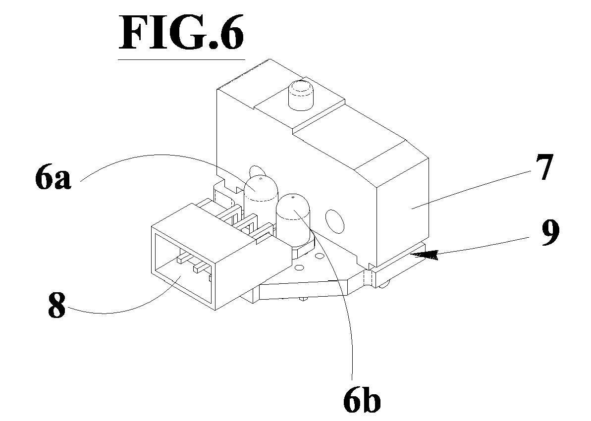
- the supporting means 9 of the light source 6, of the electrical commutation means 7 and of the connecting means 8, consists of a single board where the components are tinned thereon and are made of the two LED 6a, 6b, the microswitch 7 and the connector 8.
- the operation of the push-button 1 provides the activation of the light source whose brightness hits the inside wall of the cap 5, back-illuminating this latter and allowing the primary lighting of the bright push-button 1.
- the brightness of the light source and therefore the brightness and coloring of the cap 5 depends on the activation of one or both LED, and, as already said, it/they can emit light of the same or different color.
- the main advantage of the present invention is to supply an illuminated push-button incorporating a single supporting means for the lighting means and for the commutation and electrical connecting means.
Landscapes
- Push-Button Switches (AREA)
- Lock And Its Accessories (AREA)
- Automatic Disk Changers (AREA)
- Control Of Transmission Device (AREA)
Abstract
An illuminated push-button for game machine includes a body (2) hookable to the game machine.
Into the body (2) a sliding element is housed (3) supporting a cap (5) illuminable by means of a light source (6), consisting of two LED (6a; 6b) and internal to the push-button (1), and acting on electrical commutation means (7).
The push-button (1) includes moreover connecting means (8) to the game machine and a single supporting means (6) of the light source (6), of the electrical commutation means (7) and of the connecting means (8).


Description
- The present invention relates to game machines, and in particular it refers to an illuminated push-button for such machines.
- The known illuminated push-buttons essentially include a body for engaging the game machine and for housing a sliding element, intended for carrying out the opening and closing stroke of the push-button electrical connection, and for supporting at its upper end an overbody providing a seat for a transparent cap fit for enabling the light passage emitted by a lamp opportunely housed inside the sliding element.
- Therefore, such known push buttons are fit to operate the main functions of the game machine and, when in operation, they allow the lighting of the transparent cover.
- A drawback of the known illuminated push-button is that they incorporate a lamp support different from the micro-switch support which is separated from the electrical means of the push-button connecting to the control card of the game machine.
- Further disadvantage of the known push-buttons resides in the fact that the lighted portion, in some cases, is reduced and however is only of one color.
- The main object of the present invention is to propose an illuminated push-button incorporating a single supporting means for the lighting, commutation and connecting means.
- Further object is to propose an illuminated push-button with more than one illuminable zone also with different colorings.
- The characteristics of the invention are in the following evidenced with particular reference to the attached drawings in which:
-
figure 1 shows a perspective view of the push-button object of the present invention; -
figure 2 shows a top view of the push-button offigure 1 ; -
figure 3 shows a section according to the plan III-III of the push-button offigure 2 ; -
figure 4 shows a side-view of the unique support means of the push-button offigure 1 ; -
figure 5 shows a front view of the supporting means offigure 4 ; -
figure 6 shows a perspective view of the supporting means offigure 4 ; -
figure 7 shows the single housing of the supporting means offigure 4 . - With reference to
figures 1-7 ,numeral 1 indicates an illuminated push-button for game machine, known and not shown, that is essentially including abody 2, asliding element 3, a fixing element, the so-calledoverbody 4, acap 5, a supporting means 9, alight source 6, electrical commutation means 7, connectingmeans 8 and abolt 11. - The
body 2 is internally hollow and houses thesliding element 3 with the interposition of a spring, not shown, and outside is provided with a threaded zone to facilitate the hooking of the push-button 1 to the game machine by means of thebolt 11. - The sliding
element 3 is internally hollow, it houses thelight source 6, that consists of aLED cup - The
overbody 4 is fixed to the upper portion of thebody 2 and constitutes the peripheral viewable portion of the push-button 1. - The electrical commutation means 7 consists of a microswitch.
- The
connecting means 8 include at least a pin connector for housing the corresponding connector for the electrical connection of the push-button to the control card of the game machine. - In the preferred embodiment, the supporting means 9 of the
light source 6, of the electrical commutation means 7 and of the connectingmeans 8, consists of a single board where the components are tinned thereon and are made of the twoLED microswitch 7 and theconnector 8. - Such supporting means 9, namely printed circuit board with the components tinned thereon, is contained in a container (10) removably hookable to the lower portion of the push-
button 1 which is opposite to thecap 5. - The operation of the push-
button 1 provides the activation of the light source whose brightness hits the inside wall of thecap 5, back-illuminating this latter and allowing the primary lighting of the bright push-button 1. - The brightness of the light source and therefore the brightness and coloring of the
cap 5 depends on the activation of one or both LED, and, as already said, it/they can emit light of the same or different color. - The use of a single board 9 for supporting one or more LED, of the microswitch and of the connector allows the use of this solution in a wide variety of illuminated push-buttons, making simple the interchangeability.
- The main advantage of the present invention is to supply an illuminated push-button incorporating a single supporting means for the lighting means and for the commutation and electrical connecting means.
- Further advantage consists in supplying an illuminated push-button with more than one illuminable zone also with different colorings.
Claims (8)
- Illuminated push-button for game machine comprising a hooking body (2) to the game machine, inside the body (2) a sliding element is housed (3) bearing a cap (5) illuminable by means of at least a light source (6) inside the push-button (1) and acting on electrical commutation means (7), said button comprising moreover connecting means (8) to the game machine and being characterized by including a single supporting means (9) of the at least one light source (6), of electrical commutation means (7) and of connecting means (8).
- Illuminated push-button according to claim 1 characterized in that the only one supporting means (9) consists of a single printed circuit.
- Illuminated push-button according to claim 1 characterized in that the at least a light source (6) consists of at least one couple of LED (6a, 6b).
- Illuminated push-button according to claim 3 characterized in that the LED (6a; 6b) emit light of the same color.
- Illuminated push-button according to claim 3 characterized in that the LED (6a; 6b) emit light of different colors.
- Illuminated push-button according to claim 1 characterized in that the electrical commutation means (7) include a microswitch.
- Illuminated push-button according to claim 1 characterized in that the connecting means (8) include at least a pin connector.
- Illuminated push-button according to claim 1 characterized by comprising moreover a container (10) of the supporting means (9) hookable to the lower portion of the push-button (1) opposite to the cap (5).
Applications Claiming Priority (1)
| Application Number | Priority Date | Filing Date | Title |
|---|---|---|---|
| ITBO20090060 ITBO20090060U1 (en) | 2009-07-31 | 2009-07-31 | LIGHTED BUTTON |
Publications (1)
| Publication Number | Publication Date |
|---|---|
| EP2282315A1 true EP2282315A1 (en) | 2011-02-09 |
Family
ID=42989662
Family Applications (1)
| Application Number | Title | Priority Date | Filing Date |
|---|---|---|---|
| EP10171267A Withdrawn EP2282315A1 (en) | 2009-07-31 | 2010-07-29 | Illuminated push button |
Country Status (2)
| Country | Link |
|---|---|
| EP (1) | EP2282315A1 (en) |
| IT (1) | ITBO20090060U1 (en) |
Cited By (2)
| Publication number | Priority date | Publication date | Assignee | Title |
|---|---|---|---|---|
| CN108616779A (en) * | 2016-12-13 | 2018-10-02 | 中兴通讯股份有限公司 | A kind of operating device for single-board insert-pull |
| US10625173B2 (en) | 2014-05-15 | 2020-04-21 | Lego A/S | Toy construction system with function construction elements |
Citations (4)
| Publication number | Priority date | Publication date | Assignee | Title |
|---|---|---|---|---|
| US5150257A (en) * | 1991-07-29 | 1992-09-22 | Eaton Corporation | High reliability, low intensity back lit SR and NVGC indicator assembly |
| US6075214A (en) * | 1996-12-24 | 2000-06-13 | Koha Co., Ltd. | Push button assembly for a vending machine |
| WO2006040581A1 (en) * | 2004-10-15 | 2006-04-20 | Gamesman Limited | Push button assembly |
| EP1890308A1 (en) * | 2006-08-15 | 2008-02-20 | IGT-UK Limited | Press buttons |
-
2009
- 2009-07-31 IT ITBO20090060 patent/ITBO20090060U1/en unknown
-
2010
- 2010-07-29 EP EP10171267A patent/EP2282315A1/en not_active Withdrawn
Patent Citations (4)
| Publication number | Priority date | Publication date | Assignee | Title |
|---|---|---|---|---|
| US5150257A (en) * | 1991-07-29 | 1992-09-22 | Eaton Corporation | High reliability, low intensity back lit SR and NVGC indicator assembly |
| US6075214A (en) * | 1996-12-24 | 2000-06-13 | Koha Co., Ltd. | Push button assembly for a vending machine |
| WO2006040581A1 (en) * | 2004-10-15 | 2006-04-20 | Gamesman Limited | Push button assembly |
| EP1890308A1 (en) * | 2006-08-15 | 2008-02-20 | IGT-UK Limited | Press buttons |
Cited By (4)
| Publication number | Priority date | Publication date | Assignee | Title |
|---|---|---|---|---|
| US10625173B2 (en) | 2014-05-15 | 2020-04-21 | Lego A/S | Toy construction system with function construction elements |
| US12005372B2 (en) | 2014-05-15 | 2024-06-11 | Lego A/S | Toy construction system with function construction elements |
| CN108616779A (en) * | 2016-12-13 | 2018-10-02 | 中兴通讯股份有限公司 | A kind of operating device for single-board insert-pull |
| CN108616779B (en) * | 2016-12-13 | 2022-08-12 | 中兴通讯股份有限公司 | An operating device for single board plugging and unplugging |
Also Published As
| Publication number | Publication date |
|---|---|
| ITBO20090060U1 (en) | 2011-02-01 |
Similar Documents
| Publication | Publication Date | Title |
|---|---|---|
| AU2005293311B2 (en) | Push button assembly | |
| CA2593253A1 (en) | Color changing light object and user interface for same | |
| US5278734A (en) | Light illuminating assemblies for wearing apparel with light element securement means | |
| US9360179B2 (en) | LED night-light | |
| US6962505B1 (en) | Electrical switch with placard and remote use indicator | |
| CN102318148B (en) | Electric installation device | |
| US8418385B2 (en) | Lighting device | |
| EP2282315A1 (en) | Illuminated push button | |
| EP1811226B1 (en) | Lighting means | |
| KR101198094B1 (en) | The image display device which is affixed in the switch and the smart switch which has this | |
| CN216976839U (en) | Luminous knob | |
| CN204792566U (en) | Button on noiseless luminous mechanical keyboard | |
| ES2329278T3 (en) | LIGHTING UNIT FOR CIGARETTE LIGHTER CLAMP CAP. | |
| CN200973620Y (en) | Electrothermal vessel with lamp on the base | |
| CN213491746U (en) | Intelligent luminous rope skipping device | |
| JP2020077461A (en) | Portable light | |
| JP4555555B2 (en) | Game machine | |
| KR20100007908U (en) | Monitor Type Cigarette Signboard for Indoor | |
| US20070015591A1 (en) | Console for use in combination with an entertainment machine | |
| CN218390824U (en) | Aperture structure of bread maker | |
| JP3080957U (en) | Light-emitting diode lamps emitting polychromatic light | |
| US20060133067A1 (en) | Shoe with an illuminating heel | |
| KR200329643Y1 (en) | lightning character and number display apparatus | |
| JP2003181090A (en) | Game equipment | |
| CN217601604U (en) | Remote controller for toilet |
Legal Events
| Date | Code | Title | Description |
|---|---|---|---|
| PUAI | Public reference made under article 153(3) epc to a published international application that has entered the european phase |
Free format text: ORIGINAL CODE: 0009012 |
|
| AK | Designated contracting states |
Kind code of ref document: A1 Designated state(s): AL AT BE BG CH CY CZ DE DK EE ES FI FR GB GR HR HU IE IS IT LI LT LU LV MC MK MT NL NO PL PT RO SE SI SK SM TR |
|
| AX | Request for extension of the european patent |
Extension state: BA ME RS |
|
| STAA | Information on the status of an ep patent application or granted ep patent |
Free format text: STATUS: THE APPLICATION IS DEEMED TO BE WITHDRAWN |
|
| 18D | Application deemed to be withdrawn |
Effective date: 20110810 |