EP2218744A1 - Method of manufacturing holographic photopolymers on polymer films - Google Patents
Method of manufacturing holographic photopolymers on polymer films Download PDFInfo
- Publication number
- EP2218744A1 EP2218744A1 EP09001952A EP09001952A EP2218744A1 EP 2218744 A1 EP2218744 A1 EP 2218744A1 EP 09001952 A EP09001952 A EP 09001952A EP 09001952 A EP09001952 A EP 09001952A EP 2218744 A1 EP2218744 A1 EP 2218744A1
- Authority
- EP
- European Patent Office
- Prior art keywords
- isocyanate
- component
- film
- roll
- photopolymer
- Prior art date
- Legal status (The legal status is an assumption and is not a legal conclusion. Google has not performed a legal analysis and makes no representation as to the accuracy of the status listed.)
- Withdrawn
Links
Images


Classifications
-
- G—PHYSICS
- G03—PHOTOGRAPHY; CINEMATOGRAPHY; ANALOGOUS TECHNIQUES USING WAVES OTHER THAN OPTICAL WAVES; ELECTROGRAPHY; HOLOGRAPHY
- G03H—HOLOGRAPHIC PROCESSES OR APPARATUS
- G03H1/00—Holographic processes or apparatus using light, infrared or ultraviolet waves for obtaining holograms or for obtaining an image from them; Details peculiar thereto
- G03H1/02—Details of features involved during the holographic process; Replication of holograms without interference recording
-
- C—CHEMISTRY; METALLURGY
- C08—ORGANIC MACROMOLECULAR COMPOUNDS; THEIR PREPARATION OR CHEMICAL WORKING-UP; COMPOSITIONS BASED THEREON
- C08J—WORKING-UP; GENERAL PROCESSES OF COMPOUNDING; AFTER-TREATMENT NOT COVERED BY SUBCLASSES C08B, C08C, C08F, C08G or C08H
- C08J7/00—Chemical treatment or coating of shaped articles made of macromolecular substances
- C08J7/04—Coating
- C08J7/0427—Coating with only one layer of a composition containing a polymer binder
-
- C—CHEMISTRY; METALLURGY
- C08—ORGANIC MACROMOLECULAR COMPOUNDS; THEIR PREPARATION OR CHEMICAL WORKING-UP; COMPOSITIONS BASED THEREON
- C08G—MACROMOLECULAR COMPOUNDS OBTAINED OTHERWISE THAN BY REACTIONS ONLY INVOLVING UNSATURATED CARBON-TO-CARBON BONDS
- C08G18/00—Polymeric products of isocyanates or isothiocyanates
- C08G18/06—Polymeric products of isocyanates or isothiocyanates with compounds having active hydrogen
- C08G18/08—Processes
- C08G18/10—Prepolymer processes involving reaction of isocyanates or isothiocyanates with compounds having active hydrogen in a first reaction step
-
- C—CHEMISTRY; METALLURGY
- C08—ORGANIC MACROMOLECULAR COMPOUNDS; THEIR PREPARATION OR CHEMICAL WORKING-UP; COMPOSITIONS BASED THEREON
- C08G—MACROMOLECULAR COMPOUNDS OBTAINED OTHERWISE THAN BY REACTIONS ONLY INVOLVING UNSATURATED CARBON-TO-CARBON BONDS
- C08G18/00—Polymeric products of isocyanates or isothiocyanates
- C08G18/06—Polymeric products of isocyanates or isothiocyanates with compounds having active hydrogen
- C08G18/28—Polymeric products of isocyanates or isothiocyanates with compounds having active hydrogen characterised by the compounds used containing active hydrogen
- C08G18/40—High-molecular-weight compounds
- C08G18/48—Polyethers
- C08G18/4825—Polyethers containing two hydroxy groups
-
- C—CHEMISTRY; METALLURGY
- C08—ORGANIC MACROMOLECULAR COMPOUNDS; THEIR PREPARATION OR CHEMICAL WORKING-UP; COMPOSITIONS BASED THEREON
- C08G—MACROMOLECULAR COMPOUNDS OBTAINED OTHERWISE THAN BY REACTIONS ONLY INVOLVING UNSATURATED CARBON-TO-CARBON BONDS
- C08G18/00—Polymeric products of isocyanates or isothiocyanates
- C08G18/06—Polymeric products of isocyanates or isothiocyanates with compounds having active hydrogen
- C08G18/28—Polymeric products of isocyanates or isothiocyanates with compounds having active hydrogen characterised by the compounds used containing active hydrogen
- C08G18/40—High-molecular-weight compounds
- C08G18/48—Polyethers
- C08G18/4833—Polyethers containing oxyethylene units
- C08G18/4837—Polyethers containing oxyethylene units and other oxyalkylene units
- C08G18/4841—Polyethers containing oxyethylene units and other oxyalkylene units containing oxyethylene end groups
-
- C—CHEMISTRY; METALLURGY
- C08—ORGANIC MACROMOLECULAR COMPOUNDS; THEIR PREPARATION OR CHEMICAL WORKING-UP; COMPOSITIONS BASED THEREON
- C08G—MACROMOLECULAR COMPOUNDS OBTAINED OTHERWISE THAN BY REACTIONS ONLY INVOLVING UNSATURATED CARBON-TO-CARBON BONDS
- C08G18/00—Polymeric products of isocyanates or isothiocyanates
- C08G18/06—Polymeric products of isocyanates or isothiocyanates with compounds having active hydrogen
- C08G18/70—Polymeric products of isocyanates or isothiocyanates with compounds having active hydrogen characterised by the isocyanates or isothiocyanates used
- C08G18/72—Polyisocyanates or polyisothiocyanates
- C08G18/77—Polyisocyanates or polyisothiocyanates having heteroatoms in addition to the isocyanate or isothiocyanate nitrogen and oxygen or sulfur
- C08G18/775—Polyisocyanates or polyisothiocyanates having heteroatoms in addition to the isocyanate or isothiocyanate nitrogen and oxygen or sulfur sulfur
-
- C—CHEMISTRY; METALLURGY
- C08—ORGANIC MACROMOLECULAR COMPOUNDS; THEIR PREPARATION OR CHEMICAL WORKING-UP; COMPOSITIONS BASED THEREON
- C08G—MACROMOLECULAR COMPOUNDS OBTAINED OTHERWISE THAN BY REACTIONS ONLY INVOLVING UNSATURATED CARBON-TO-CARBON BONDS
- C08G18/00—Polymeric products of isocyanates or isothiocyanates
- C08G18/06—Polymeric products of isocyanates or isothiocyanates with compounds having active hydrogen
- C08G18/70—Polymeric products of isocyanates or isothiocyanates with compounds having active hydrogen characterised by the isocyanates or isothiocyanates used
- C08G18/72—Polyisocyanates or polyisothiocyanates
- C08G18/77—Polyisocyanates or polyisothiocyanates having heteroatoms in addition to the isocyanate or isothiocyanate nitrogen and oxygen or sulfur
- C08G18/776—Polyisocyanates or polyisothiocyanates having heteroatoms in addition to the isocyanate or isothiocyanate nitrogen and oxygen or sulfur phosphorus
-
- C—CHEMISTRY; METALLURGY
- C08—ORGANIC MACROMOLECULAR COMPOUNDS; THEIR PREPARATION OR CHEMICAL WORKING-UP; COMPOSITIONS BASED THEREON
- C08G—MACROMOLECULAR COMPOUNDS OBTAINED OTHERWISE THAN BY REACTIONS ONLY INVOLVING UNSATURATED CARBON-TO-CARBON BONDS
- C08G18/00—Polymeric products of isocyanates or isothiocyanates
- C08G18/06—Polymeric products of isocyanates or isothiocyanates with compounds having active hydrogen
- C08G18/70—Polymeric products of isocyanates or isothiocyanates with compounds having active hydrogen characterised by the isocyanates or isothiocyanates used
- C08G18/72—Polyisocyanates or polyisothiocyanates
- C08G18/77—Polyisocyanates or polyisothiocyanates having heteroatoms in addition to the isocyanate or isothiocyanate nitrogen and oxygen or sulfur
- C08G18/78—Nitrogen
- C08G18/7806—Nitrogen containing -N-C=0 groups
- C08G18/7818—Nitrogen containing -N-C=0 groups containing ureum or ureum derivative groups
- C08G18/7837—Nitrogen containing -N-C=0 groups containing ureum or ureum derivative groups containing allophanate groups
-
- C—CHEMISTRY; METALLURGY
- C08—ORGANIC MACROMOLECULAR COMPOUNDS; THEIR PREPARATION OR CHEMICAL WORKING-UP; COMPOSITIONS BASED THEREON
- C08G—MACROMOLECULAR COMPOUNDS OBTAINED OTHERWISE THAN BY REACTIONS ONLY INVOLVING UNSATURATED CARBON-TO-CARBON BONDS
- C08G18/00—Polymeric products of isocyanates or isothiocyanates
- C08G18/06—Polymeric products of isocyanates or isothiocyanates with compounds having active hydrogen
- C08G18/70—Polymeric products of isocyanates or isothiocyanates with compounds having active hydrogen characterised by the isocyanates or isothiocyanates used
- C08G18/81—Unsaturated isocyanates or isothiocyanates
- C08G18/8141—Unsaturated isocyanates or isothiocyanates masked
- C08G18/815—Polyisocyanates or polyisothiocyanates masked with unsaturated compounds having active hydrogen
- C08G18/8158—Polyisocyanates or polyisothiocyanates masked with unsaturated compounds having active hydrogen with unsaturated compounds having only one group containing active hydrogen
- C08G18/8175—Polyisocyanates or polyisothiocyanates masked with unsaturated compounds having active hydrogen with unsaturated compounds having only one group containing active hydrogen with esters of acrylic or alkylacrylic acid having only one group containing active hydrogen
-
- C—CHEMISTRY; METALLURGY
- C08—ORGANIC MACROMOLECULAR COMPOUNDS; THEIR PREPARATION OR CHEMICAL WORKING-UP; COMPOSITIONS BASED THEREON
- C08J—WORKING-UP; GENERAL PROCESSES OF COMPOUNDING; AFTER-TREATMENT NOT COVERED BY SUBCLASSES C08B, C08C, C08F, C08G or C08H
- C08J5/00—Manufacture of articles or shaped materials containing macromolecular substances
- C08J5/18—Manufacture of films or sheets
-
- C—CHEMISTRY; METALLURGY
- C08—ORGANIC MACROMOLECULAR COMPOUNDS; THEIR PREPARATION OR CHEMICAL WORKING-UP; COMPOSITIONS BASED THEREON
- C08J—WORKING-UP; GENERAL PROCESSES OF COMPOUNDING; AFTER-TREATMENT NOT COVERED BY SUBCLASSES C08B, C08C, C08F, C08G or C08H
- C08J7/00—Chemical treatment or coating of shaped articles made of macromolecular substances
- C08J7/04—Coating
- C08J7/043—Improving the adhesiveness of the coatings per se, e.g. forming primers
-
- C—CHEMISTRY; METALLURGY
- C08—ORGANIC MACROMOLECULAR COMPOUNDS; THEIR PREPARATION OR CHEMICAL WORKING-UP; COMPOSITIONS BASED THEREON
- C08L—COMPOSITIONS OF MACROMOLECULAR COMPOUNDS
- C08L75/00—Compositions of polyureas or polyurethanes; Compositions of derivatives of such polymers
- C08L75/04—Polyurethanes
- C08L75/14—Polyurethanes having carbon-to-carbon unsaturated bonds
- C08L75/16—Polyurethanes having carbon-to-carbon unsaturated bonds having terminal carbon-to-carbon unsaturated bonds
-
- G—PHYSICS
- G03—PHOTOGRAPHY; CINEMATOGRAPHY; ANALOGOUS TECHNIQUES USING WAVES OTHER THAN OPTICAL WAVES; ELECTROGRAPHY; HOLOGRAPHY
- G03F—PHOTOMECHANICAL PRODUCTION OF TEXTURED OR PATTERNED SURFACES, e.g. FOR PRINTING, FOR PROCESSING OF SEMICONDUCTOR DEVICES; MATERIALS THEREFOR; ORIGINALS THEREFOR; APPARATUS SPECIALLY ADAPTED THEREFOR
- G03F7/00—Photomechanical, e.g. photolithographic, production of textured or patterned surfaces, e.g. printing surfaces; Materials therefor, e.g. comprising photoresists; Apparatus specially adapted therefor
- G03F7/0005—Production of optical devices or components in so far as characterised by the lithographic processes or materials used therefor
- G03F7/001—Phase modulating patterns, e.g. refractive index patterns
-
- G—PHYSICS
- G03—PHOTOGRAPHY; CINEMATOGRAPHY; ANALOGOUS TECHNIQUES USING WAVES OTHER THAN OPTICAL WAVES; ELECTROGRAPHY; HOLOGRAPHY
- G03F—PHOTOMECHANICAL PRODUCTION OF TEXTURED OR PATTERNED SURFACES, e.g. FOR PRINTING, FOR PROCESSING OF SEMICONDUCTOR DEVICES; MATERIALS THEREFOR; ORIGINALS THEREFOR; APPARATUS SPECIALLY ADAPTED THEREFOR
- G03F7/00—Photomechanical, e.g. photolithographic, production of textured or patterned surfaces, e.g. printing surfaces; Materials therefor, e.g. comprising photoresists; Apparatus specially adapted therefor
- G03F7/004—Photosensitive materials
- G03F7/027—Non-macromolecular photopolymerisable compounds having carbon-to-carbon double bonds, e.g. ethylenic compounds
- G03F7/032—Non-macromolecular photopolymerisable compounds having carbon-to-carbon double bonds, e.g. ethylenic compounds with binders
- G03F7/035—Non-macromolecular photopolymerisable compounds having carbon-to-carbon double bonds, e.g. ethylenic compounds with binders the binders being polyurethanes
-
- G—PHYSICS
- G03—PHOTOGRAPHY; CINEMATOGRAPHY; ANALOGOUS TECHNIQUES USING WAVES OTHER THAN OPTICAL WAVES; ELECTROGRAPHY; HOLOGRAPHY
- G03H—HOLOGRAPHIC PROCESSES OR APPARATUS
- G03H1/00—Holographic processes or apparatus using light, infrared or ultraviolet waves for obtaining holograms or for obtaining an image from them; Details peculiar thereto
- G03H1/04—Processes or apparatus for producing holograms
-
- G—PHYSICS
- G11—INFORMATION STORAGE
- G11B—INFORMATION STORAGE BASED ON RELATIVE MOVEMENT BETWEEN RECORD CARRIER AND TRANSDUCER
- G11B7/00—Recording or reproducing by optical means, e.g. recording using a thermal beam of optical radiation by modifying optical properties or the physical structure, reproducing using an optical beam at lower power by sensing optical properties; Record carriers therefor
- G11B7/24—Record carriers characterised by shape, structure or physical properties, or by the selection of the material
- G11B7/241—Record carriers characterised by shape, structure or physical properties, or by the selection of the material characterised by the selection of the material
- G11B7/242—Record carriers characterised by shape, structure or physical properties, or by the selection of the material characterised by the selection of the material of recording layers
- G11B7/244—Record carriers characterised by shape, structure or physical properties, or by the selection of the material characterised by the selection of the material of recording layers comprising organic materials only
- G11B7/245—Record carriers characterised by shape, structure or physical properties, or by the selection of the material characterised by the selection of the material of recording layers comprising organic materials only containing a polymeric component
-
- C—CHEMISTRY; METALLURGY
- C08—ORGANIC MACROMOLECULAR COMPOUNDS; THEIR PREPARATION OR CHEMICAL WORKING-UP; COMPOSITIONS BASED THEREON
- C08G—MACROMOLECULAR COMPOUNDS OBTAINED OTHERWISE THAN BY REACTIONS ONLY INVOLVING UNSATURATED CARBON-TO-CARBON BONDS
- C08G18/00—Polymeric products of isocyanates or isothiocyanates
- C08G18/06—Polymeric products of isocyanates or isothiocyanates with compounds having active hydrogen
- C08G18/70—Polymeric products of isocyanates or isothiocyanates with compounds having active hydrogen characterised by the isocyanates or isothiocyanates used
- C08G18/72—Polyisocyanates or polyisothiocyanates
- C08G18/77—Polyisocyanates or polyisothiocyanates having heteroatoms in addition to the isocyanate or isothiocyanate nitrogen and oxygen or sulfur
-
- C—CHEMISTRY; METALLURGY
- C08—ORGANIC MACROMOLECULAR COMPOUNDS; THEIR PREPARATION OR CHEMICAL WORKING-UP; COMPOSITIONS BASED THEREON
- C08J—WORKING-UP; GENERAL PROCESSES OF COMPOUNDING; AFTER-TREATMENT NOT COVERED BY SUBCLASSES C08B, C08C, C08F, C08G or C08H
- C08J2323/00—Characterised by the use of homopolymers or copolymers of unsaturated aliphatic hydrocarbons having only one carbon-to-carbon double bond; Derivatives of such polymers
- C08J2323/02—Characterised by the use of homopolymers or copolymers of unsaturated aliphatic hydrocarbons having only one carbon-to-carbon double bond; Derivatives of such polymers not modified by chemical after treatment
- C08J2323/04—Homopolymers or copolymers of ethene
- C08J2323/06—Polyethene
-
- C—CHEMISTRY; METALLURGY
- C08—ORGANIC MACROMOLECULAR COMPOUNDS; THEIR PREPARATION OR CHEMICAL WORKING-UP; COMPOSITIONS BASED THEREON
- C08J—WORKING-UP; GENERAL PROCESSES OF COMPOUNDING; AFTER-TREATMENT NOT COVERED BY SUBCLASSES C08B, C08C, C08F, C08G or C08H
- C08J2367/00—Characterised by the use of polyesters obtained by reactions forming a carboxylic ester link in the main chain; Derivatives of such polymers
- C08J2367/02—Polyesters derived from dicarboxylic acids and dihydroxy compounds
-
- C—CHEMISTRY; METALLURGY
- C08—ORGANIC MACROMOLECULAR COMPOUNDS; THEIR PREPARATION OR CHEMICAL WORKING-UP; COMPOSITIONS BASED THEREON
- C08J—WORKING-UP; GENERAL PROCESSES OF COMPOUNDING; AFTER-TREATMENT NOT COVERED BY SUBCLASSES C08B, C08C, C08F, C08G or C08H
- C08J2471/00—Characterised by the use of polyethers obtained by reactions forming an ether link in the main chain; Derivatives of such polymers
-
- C—CHEMISTRY; METALLURGY
- C08—ORGANIC MACROMOLECULAR COMPOUNDS; THEIR PREPARATION OR CHEMICAL WORKING-UP; COMPOSITIONS BASED THEREON
- C08J—WORKING-UP; GENERAL PROCESSES OF COMPOUNDING; AFTER-TREATMENT NOT COVERED BY SUBCLASSES C08B, C08C, C08F, C08G or C08H
- C08J2475/00—Characterised by the use of polyureas or polyurethanes; Derivatives of such polymers
- C08J2475/04—Polyurethanes
-
- C—CHEMISTRY; METALLURGY
- C09—DYES; PAINTS; POLISHES; NATURAL RESINS; ADHESIVES; COMPOSITIONS NOT OTHERWISE PROVIDED FOR; APPLICATIONS OF MATERIALS NOT OTHERWISE PROVIDED FOR
- C09D—COATING COMPOSITIONS, e.g. PAINTS, VARNISHES OR LACQUERS; FILLING PASTES; CHEMICAL PAINT OR INK REMOVERS; INKS; CORRECTING FLUIDS; WOODSTAINS; PASTES OR SOLIDS FOR COLOURING OR PRINTING; USE OF MATERIALS THEREFOR
- C09D175/00—Coating compositions based on polyureas or polyurethanes; Coating compositions based on derivatives of such polymers
- C09D175/04—Polyurethanes
- C09D175/08—Polyurethanes from polyethers
-
- G—PHYSICS
- G03—PHOTOGRAPHY; CINEMATOGRAPHY; ANALOGOUS TECHNIQUES USING WAVES OTHER THAN OPTICAL WAVES; ELECTROGRAPHY; HOLOGRAPHY
- G03H—HOLOGRAPHIC PROCESSES OR APPARATUS
- G03H1/00—Holographic processes or apparatus using light, infrared or ultraviolet waves for obtaining holograms or for obtaining an image from them; Details peculiar thereto
- G03H1/02—Details of features involved during the holographic process; Replication of holograms without interference recording
- G03H2001/026—Recording materials or recording processes
- G03H2001/0264—Organic recording material
-
- G—PHYSICS
- G03—PHOTOGRAPHY; CINEMATOGRAPHY; ANALOGOUS TECHNIQUES USING WAVES OTHER THAN OPTICAL WAVES; ELECTROGRAPHY; HOLOGRAPHY
- G03H—HOLOGRAPHIC PROCESSES OR APPARATUS
- G03H2260/00—Recording materials or recording processes
- G03H2260/12—Photopolymer
-
- G—PHYSICS
- G03—PHOTOGRAPHY; CINEMATOGRAPHY; ANALOGOUS TECHNIQUES USING WAVES OTHER THAN OPTICAL WAVES; ELECTROGRAPHY; HOLOGRAPHY
- G03H—HOLOGRAPHIC PROCESSES OR APPARATUS
- G03H2260/00—Recording materials or recording processes
- G03H2260/30—Details of photosensitive recording material not otherwise provided for
-
- G—PHYSICS
- G11—INFORMATION STORAGE
- G11B—INFORMATION STORAGE BASED ON RELATIVE MOVEMENT BETWEEN RECORD CARRIER AND TRANSDUCER
- G11B7/00—Recording or reproducing by optical means, e.g. recording using a thermal beam of optical radiation by modifying optical properties or the physical structure, reproducing using an optical beam at lower power by sensing optical properties; Record carriers therefor
- G11B7/24—Record carriers characterised by shape, structure or physical properties, or by the selection of the material
- G11B7/2403—Layers; Shape, structure or physical properties thereof
- G11B7/24035—Recording layers
- G11B7/24044—Recording layers for storing optical interference patterns, e.g. holograms; for storing data in three dimensions, e.g. volume storage
-
- G—PHYSICS
- G11—INFORMATION STORAGE
- G11B—INFORMATION STORAGE BASED ON RELATIVE MOVEMENT BETWEEN RECORD CARRIER AND TRANSDUCER
- G11B7/00—Recording or reproducing by optical means, e.g. recording using a thermal beam of optical radiation by modifying optical properties or the physical structure, reproducing using an optical beam at lower power by sensing optical properties; Record carriers therefor
- G11B7/24—Record carriers characterised by shape, structure or physical properties, or by the selection of the material
- G11B7/241—Record carriers characterised by shape, structure or physical properties, or by the selection of the material characterised by the selection of the material
- G11B7/252—Record carriers characterised by shape, structure or physical properties, or by the selection of the material characterised by the selection of the material of layers other than recording layers
- G11B7/253—Record carriers characterised by shape, structure or physical properties, or by the selection of the material characterised by the selection of the material of layers other than recording layers of substrates
- G11B7/2533—Record carriers characterised by shape, structure or physical properties, or by the selection of the material characterised by the selection of the material of layers other than recording layers of substrates comprising resins
- G11B7/2535—Record carriers characterised by shape, structure or physical properties, or by the selection of the material characterised by the selection of the material of layers other than recording layers of substrates comprising resins polyesters, e.g. PET, PETG or PEN
-
- G—PHYSICS
- G11—INFORMATION STORAGE
- G11B—INFORMATION STORAGE BASED ON RELATIVE MOVEMENT BETWEEN RECORD CARRIER AND TRANSDUCER
- G11B7/00—Recording or reproducing by optical means, e.g. recording using a thermal beam of optical radiation by modifying optical properties or the physical structure, reproducing using an optical beam at lower power by sensing optical properties; Record carriers therefor
- G11B7/24—Record carriers characterised by shape, structure or physical properties, or by the selection of the material
- G11B7/241—Record carriers characterised by shape, structure or physical properties, or by the selection of the material characterised by the selection of the material
- G11B7/252—Record carriers characterised by shape, structure or physical properties, or by the selection of the material characterised by the selection of the material of layers other than recording layers
- G11B7/253—Record carriers characterised by shape, structure or physical properties, or by the selection of the material characterised by the selection of the material of layers other than recording layers of substrates
- G11B7/2533—Record carriers characterised by shape, structure or physical properties, or by the selection of the material characterised by the selection of the material of layers other than recording layers of substrates comprising resins
- G11B7/2536—Record carriers characterised by shape, structure or physical properties, or by the selection of the material characterised by the selection of the material of layers other than recording layers of substrates comprising resins polystyrene [PS]
-
- G—PHYSICS
- G11—INFORMATION STORAGE
- G11B—INFORMATION STORAGE BASED ON RELATIVE MOVEMENT BETWEEN RECORD CARRIER AND TRANSDUCER
- G11B7/00—Recording or reproducing by optical means, e.g. recording using a thermal beam of optical radiation by modifying optical properties or the physical structure, reproducing using an optical beam at lower power by sensing optical properties; Record carriers therefor
- G11B7/24—Record carriers characterised by shape, structure or physical properties, or by the selection of the material
- G11B7/241—Record carriers characterised by shape, structure or physical properties, or by the selection of the material characterised by the selection of the material
- G11B7/252—Record carriers characterised by shape, structure or physical properties, or by the selection of the material characterised by the selection of the material of layers other than recording layers
- G11B7/253—Record carriers characterised by shape, structure or physical properties, or by the selection of the material characterised by the selection of the material of layers other than recording layers of substrates
- G11B7/2533—Record carriers characterised by shape, structure or physical properties, or by the selection of the material characterised by the selection of the material of layers other than recording layers of substrates comprising resins
- G11B7/2538—Record carriers characterised by shape, structure or physical properties, or by the selection of the material characterised by the selection of the material of layers other than recording layers of substrates comprising resins polycycloolefins [PCO]
Definitions
- the invention relates to a method for producing novel photopolymers based on prepolymer-based polyurethane compositions, which are suitable for the production of holographic media, in particular for the visual display of images.
- Photopolymers are materials which can be exposed by the superposition of two coherent light sources, forming a three-dimensional structure in the photopolymers, which can generally be described by a regional change in the refractive index in the material. Such structures are called holograms. They can also be described as diffractive optical elements. It depends on the specific exposure, which optical functions such a hologram forms.
- Film coating is generally understood to mean the application of a liquid substance to a moving film material.
- the coating methods differ among others according to the properties of the layer to be applied (e.g., viscosity, surface tension, solid concentration, etc.), the target layer thickness to be applied, or the production speed.
- the coating material to be applied can be stored either in a trough or in the gap between two horizontally arranged rollers for metering.
- the speed of the wetted rollers, the procurement (screening, smooth rolling) of the roller, viscosity and surface tension, the applied layer thickness in relation to the Substratgcschwindtechnik are used, which cause a further stretching of the coating material due to differently adapted rotational speeds of the rollers and a defined gap spacing between two rollers.
- roller speed, gap distance, substrate speed and viscosity are critical factors in setting desired wet film thicknesses.
- the product is intended to be a film composite of bast film, photopolymer and a cover film.
- photopolymer films obtainable by the process according to the invention which are suitable for recording visual holograms and their further use as optical elements, images or for image display or projection.
- prepolymers are used, which in a well-known manner to the skilled worker by reaction of monomeric, oligomeric or polyisocyanates A1) with isocyanate-reactive compounds A2) in a suitable stoichiometry with the optional use of catalysts and solvents can be obtained.
- Preferred prepolymers are urethanes or allophanates of aliphatic isocyanate-functional compounds and oligomeric or polymeric isocyanate-reactive compounds, the prepolymers having number average molecular weights of from 200 to 10,000 g / mol and NCO functionality of from 1.9 to 5.0.
- difunctional urethanes and allophanates having functionalities of from greater than 1.9 to 3.2 or from 3.9 to 4.2, with number-average molar masses of from 650 to 8,200 g / mo, prepared from aliphatic isocyanate-functional compounds and oligomeric or polymeric polyols or any mixtures thereof.
- urethanes having NCO functionalities of from 1.9 to 2.1 and number average molar masses of from 1900 to 4100 g / mol prepared from aliphatic isocyanate-functional compounds and oligomeric or polymeric polyols and allophanates having functionalities greater than 2.0 to 3.2 or from 3.9 to 4.2 with number average molecular weights of 1900 to 4100 g / mol, prepared from aliphatic isocyanate-functional compounds and oligomeric or polymeric polyols or any mixtures thereof.
- component B) isocyanate-reactive polyether polyols are used, which preferably have on average at least 1.5 isocyanate-reactive groups per molecule.
- Preferred compounds of component B) are poly (propylene oxide) s, poly (ethylene oxides) and combinations thereof in the form of random or block copolymers and block copolymers of propylene oxide and / or ethylene oxide.
- the Ethylenexidanteil based on weight percent of the total product is preferably less than 55%, more preferably either between 55% and 45% or less than 30% and most preferably less than 10%.
- Very particularly preferred compounds of component B) are difunctional polyether polyols based on propylene oxide and ethylene oxide with an ethylene oxide content of less than 10 percent by weight, based on the total mass of the underlying polyether, and a number average molecular weight between 2000 and 4200 g / mol.
- the components A) and B) are used in the preparation of the photopolymer formulation in an OH / NCO ratio to each other of typically 0.9 to 1.2, preferably 0.95 to 1.05.
- urethane acrylates and / or urethane methacrylates having at least one aromatic structural unit and a refractive index of greater than 1.50 at 405 nm.
- Urethane (meth) acrylates are understood as meaning compounds having at least one acrylate or methacrylate group which additionally have at least one urethane bond.
- Particularly preferred compounds to be used as component C) are urethane acrylates and urethane methacrylates based on aromatic isocyanates and 2-hydroxyethyl acrylate, hydroxypropyl acrylate, 4-hydroxybutyl acrylate, polyethylene oxide mono (meth) acrylate, polypropylene oxide mono (meth) acrylate, polyalkylene oxide mono (meth) acrylate and poly ( ⁇ -caprolactone) mono (meth) acrylates.
- component C) the Addition products of aromatic triisocyanate (very particularly preferably tris (4-phenyl isocyanato) thiophosphate or trimers of aromatic diisocyanates such as tolylene diisocyanate) with hydroxyethyl acrylate, hydroxypropyl acrylate, 4-hydroxybutyl acrylate used.
- aromatic triisocyanate very particularly preferably tris (4-phenyl isocyanato) thiophosphate or trimers of aromatic diisocyanates such as tolylene diisocyanate
- 3-thiomethylphenyl isocyanate with hydroxyethyl acrylate, hydroxypropyl acrylate, 4-hydroxybutyl acrylate are used as component C.
- Suitable compounds of component D) are inhibitors and antioxidants. Preference is given to 2,6-di- tert- butyl-4-methylphenol, phenothiazine, p-methyoxyphenol, 2-methoxy-p-hydroquinone and benzhydrol.
- photoinitiators E are mixtures of tetrabutylammonium tetrahexylborate, tetrabutylammonium triphenylhexylborate, tetrabutylammonium tris (3-fluorophenyl) hexylborate and tetrabutylammonium tris (3-chloro-4-methylphenyl) hexylborate (component E1)) with dyes such as Astrazon Orange G, for example , Methylene blue, new methylene blue, azure A, pyrillium I, safranine O, cyanine, gallocyanine, brilliant green, crystal violet, ethyl violet and thionine (component E2)).
- Astrazon Orange G for example , Methylene blue, new methylene blue, azure A, pyrillium I, safranine O, cyanine, gallocyanine, brilliant green, crystal violet, ethyl
- catalysts As compounds of component F) it is optionally possible to use one or more catalysts.
- additives G can be used.
- these may be, for example, conventional additives in the field of coating technology, such as solvents, plasticizers, leveling agents, defoaming agents or adhesion promoters.
- the plasticizers used are preferably liquids having good release properties, low volatility and high boiling point.
- As a leveling agent surface-active compounds such as e.g. Polydimethylsiloxanes are used. It may also be advantageous to simultaneously use several additives of one type. Of course, it may also be advantageous to use several additives of several types.
- Preferred metering amounts depend on the dimensioning of the carrier film to be coated, but are usually in the range from 2 ml / min to 2000 ml / min, more preferably in the range from 2 ml / min to 500 ml / min.
- degassing (II) of the individual components or of the entire mixture can also be carried out under a reduced pressure of, for example, 1 mbar. Degassing, especially after addition of component A), is preferred to prevent blistering by residual gases or readily volatilizable components in the prepared photopolymers.
- Degassing removes dissolved gases or readily volatilizable components, such as mildly volatile solvents (e.g., ambient air) from the fluids, and optionally, can additionally saturate the fluid being degassed.
- mildly volatile solvents e.g., ambient air
- degassers vacuum degassers, membrane deaerators, centrifugal deaerators, ultrasonic deaerators and thin-film deaerators and combinations of the mentioned technologies can be used.
- the filtration (III) serves to separate solid particles from the liquid medium and is used especially as a cleaning step for the liquid components.
- Candle filters and plate filters are generally used in the coating industry.
- Preferred particle size distributions are between 0.1 ⁇ m and 5 ⁇ m, particularly preferred particle size distributions are in the range of 0.2 ⁇ m and 1 ⁇ m.
- the temperatures are from 0 to 100.degree. C., preferably from 10 to 80.degree. C., particularly preferably from 20 to 60.degree.
- the mixtures of components B) to G) can be stored as a storage-stable intermediate, if appropriate for several months.
- component A) of the polyurethane compositions according to the invention After admixture of component A) of the polyurethane compositions according to the invention, a clear, liquid formulation is obtained which, depending on the composition, cures at room temperature within a few seconds to a few hours.
- the ratio and the type and reactivity of the structural components of the polyurethane compositions is preferably adjusted so that the curing occurs after admixture of component A) at room temperature within minutes to one hour.
- the curing is accelerated by the formulation after the admixture to temperatures between 30 and 180 ° C, preferably 40 to 120 ° C, particularly preferably 50 to 100 ° C is heated.
- the polyurethane compositions have immediately after complete mixing of all components viscosities at 25 ° C of typically 10 to 100,000 mPas, preferably 100 to 20,000 mPas, more preferably 200 to 10,000 mPas, particularly preferably 500 to 5000 mPas so that they are already in solvent-free form very good processing technology Own properties.
- viscosities at 25 ° C below 10000 mPas, preferably below 2000 mPas, more preferably below 500 mPas can be adjusted.
- Polyurethane compositions of the abovementioned type which cure with a catalyst content (component F) of 0.004% by weight to 0.1% by weight at 80 ° C. for less than 6 minutes have proven advantageous, concentrations between 0.01% by weight are preferred. % and 0.08 wt .-%, more preferably concentrations between 0.04 wt .-% and 0.06 wt .-%.
- V The development (V) of the carrier material takes place in discontinuous processes with single-roll unwinders known to the person skilled in the art.
- a single uncoated roll is used in the Weighing device and fed to the coating process in full length.
- the coating process is interrupted and the finished coated and wound carrier material is removed from the process at the winding station and packaged product-specifically.
- a new uncoated roll is inserted and attached to the end of the pre-produced substrate with suitable adhesive sheets. After starting the machine preference of the carrier material can be continued with the coating process.
- Continuous coating of substrates involves the use of multi-roll unwinders arranged as indexable wipers or reversing crosses.
- the critical transition from a discontinuous process of using an uncoated substrate roll to a continuous coating process without this coating process is carried out either with the aid of a web memory or a flying Anklebreaes known in the art.
- a web memory serves as a buffer for the phase of standstill during roll change and sticking of the roll handling.
- the preferred speed is gradually increased to a value above the actual optimal Besehichtungs york.
- the web store is filled with carrier material until it is complete.
- the preferred speed is adapted to the actual Boschichtungs für
- the beginning of the roll already loaded on the second material unwinder is fastened to the end of the preceding roll with correspondingly suitable adhesive materials.
- the preferred speed is restarted and incrementally raised above the coating speed to refill the web store.
- the multi-roll unwinder (in the form of a disk or as a turning cross) is swiveled through 180 ° C.
- the coating speed is kept constant via the process control with the help of additional auxiliary drives.
- web control units To control the carrier material in the transverse direction to the preferred direction known in the art web control units are used.
- the position of the web edge is determined by means of optical sensors, e.g. Reflection sensors, transmission light sensors or ultrasonic sensors are determined and mechanically corrected by means of control roller systems, which are positioned on a driven rotating frame.
- contacting and non-contact surface cleaning When cleaning the substrate, a distinction is made between two different cleaning methods: contacting and non-contact surface cleaning.
- the contacting cleaning process involves cleaning brushes equipped with special soft brush materials. Disadvantage of this method is the occurrence of disturbances in the carrier material, which can be caused by the contact of the brush with the carrier material. In this regard, process parameters such as rotational speed, brush material, and the distance to the carrier material have to be adapted.
- Non-contact methods such as ionization units, suction channels or air blowers, are material-protecting processes in this regard. These ionization units generate positive and negative ions that neutralize the surface charges on the substrate. This will be Static charges on the substrate that cause dust and particles to attract from the environment are avoided.
- the cleaning systems are equipped with additional suction channels, which remove particles from the surface of the carrier material. This is supported by the use of a specially arranged flat jet nozzle, which with a fine compressed air jet dust and particles from the surface and blow away. These particles are also transported away via the installed suction ducts and filtered.
- the described methods for web cleaning can be arranged and combined in any order and positioning.
- corona and plasma pretreatment systems are used.
- the substrate is subjected to a high voltage electronic discharge that occurs between a grounded and polished steel or aluminum roller and a tight-fitting insulated electrode. Only the side facing the electrode is treated.
- Common electrodes are supplied with high-frequency generators with an alternating voltage of 10 to 20 kV and a frequency between 10 and 60 kHz.
- doctoring, casting, printing, screen printing, spraying, or inkjet printing are suitable, in particular doctoring, casting, printing, screen printing, spraying, or inkjet printing.
- doctor blades and slot dies are suitable as film coating methods.
- surface tensions of the polyurethane compositions described are adapted to the person skilled in the art with the aid of the additives described.
- Preferred surface tensions are between 10 mN / m and 50 mN / m, more preferably from 20 mN / m to 40 mN / m.
- Preferred BeJssungsumblen lie between 100 mm and 3000 mm, more preferably widths in the range of 300 mm to 2000 mm.
- Substrate speeds are preferably in the range of 0.2 m / min to 300 m / min. Particularly preferred substrate speeds are found in the range of 1.0 m / min to 50 m / min.
- Applied dry film thicknesses for doctor blade and slot nozzles are preferably not more than 200 .mu.m, more preferably from 3 .mu.m to 100 .mu.m, very particularly preferably from 15 .mu.m to 60 .mu.m.
- the drying (VII) of the coated substrate is preferably carried out at a temperature of 30 ° C and 180 ° C, more preferably from 40 ° C to 120 ° C, most preferably from 50 ° C to 100 ° C.
- the metering of the starting materials takes place either by gear pumps or eccentric screw pumps.
- centrifugal deaerator and for filtering plate filters are used for degassing the feedstock centrifugal deaerator and for filtering plate filters.
- the mixture of the individual components takes place via a static mixer with correspondingly designed mixing geometries, such as length and diameter.
- a slot nozzle is used as a preferred coating unit.
- the coated material is dried over air dryers with the desired air temperature and moisture content over a defined period of time.
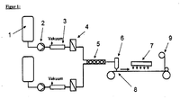
- FIG. 1 shows an overview of the described combination of the individual production steps of a coated substrate.
- FIG. 1 Schematic structure of a typical coating system, including arrangement of the pretreatment of the coating material (1-5), schematic course of the carrier material (8 + 9), coating device for application to a carrier material (6) and subsequent drying process (7).
- Another object of the present invention is the article obtained by coating a transparent substrate with the described prepolymer-based polyurethane formulation.
- This is a light-sensitive (spectral wavelength range 400 to 800 nm of the electromagnetic spectrum) product which is a film composite of at least Begussfolie or substrate (substrate), the photopolymer layer consisting of the described formulation is produced and a cover or laminating film.
- the film composite may contain other films.
- Preferred materials or composite materials of the carrier layer are based on polycarbonate (PC), polyethylene terephthalate (PET), polybutylene terephthalate, polyethylene, polypropylene, cellulose acetate, cellulose hydrate, cellulose nitrate, cycloolefin polymers, polystyrene, polyepoxides, polysulfone, cellulose triacetate (CTA), polyamide, polymethyl methacrylate, polyvinyl chloride, polyvinyl butyral or polydicyclopentadiene or mixtures thereof.
- material composites such as film laminates or coextrudates can be used as carrier film.
- PC and PET are particularly preferably used as a carrier film.
- Haze is measurable over the Haze value which is less than 3.5%, preferably less than 1%, more preferably less than 0.3%.
- the Haze value describes the proportion of transmitted light that is scattered forward by the irradiated sample. Thus, it is a measure of the opacity or turbidity of transparent materials and quantifies material defects, particles, inhomogeneities, or crystalline phase boundaries in the material or its surface that interfere with clear viewing.
- the method of measuring turbidity is described in the standard ASTM D 1003.
- the support has a not too high birefringence, i. typically has a mean optical retardation of less than 1000 nm, preferably less than 700 nm, more preferably less than 300 nm.
- the retardation R is the mathematical product of the birefringence ⁇ n and the thickness of the carrier d.
- the automatic and objective measurement of the retardation is carried out with an imaging polarimeter, e.g. from the company ilis GmbH, model StainMatic® M3 / M.
- the retardation is measured in vertical incidence.
- the values given for the wearer for the retardation are lateral averages.
- the support typically has a thickness of 5 to 2000 .mu.m, preferably 8 to 300 .mu.m, particularly preferably 30 to 200 .mu.m and in particular 125 to 175 .mu.m or 30 to 45 .mu.m.
- constituents can have one or more cover layers on the photopolymer layer for the film composite in order to protect them from dirt and environmental influences.
- cover layers plastic films or composite film systems, but also clearcoats can be used.
- film materials analogous to the materials used in the carrier layer, these having a thickness of typically 5 to 200 .mu.m, preferably 8 to 125 .mu.m, particularly preferably 20 to 50 .mu.m.
- the roughness is determined according to DIN EN ISO 4288 "Geometrical Product Specification (GPS) - surface texture " (English: “Geometrical Product Specifications (GPS) - Surface texture ##), test condition R3z front side and rear side are preferred roughness in the range less than or equal to 2 microns, preferably less than or equal to 0.5 microns.
- laminating PE or PET films of a thickness of 20 to 60 microns are preferably used, more preferably a polyethylene film of 40 microns thickness is used.
- Another object of the present invention is the use of the media according to the invention for recording visual holograms, for the production of optical elements, images, representations and a method for recording holograms using the polyurethane compositions according to the invention and the media or holographic films accessible therefrom.
- holograms for optical applications in the entire visible range and in the near UV range can be produced by appropriate exposure processes.
- Visual holograms include all holograms that can be recorded by methods known to those skilled in the art, including, but are not limited to, in-line (gabor) holograms, off-axis holograms, full-aperture transfer holograms, white-light transmission holograms ("rainbow holograms"), denisyuk holograms, Off-axis reflection holograms, edge-lit holograms and holographic stereograms, preference is given to reflection holograms, denisy-holograms, transmission holograms.
- optical elements such as lenses, mirrors, deflection mirrors, filters, diffusers, diffractive elements, light guides, waveguides, projection screens and / or Have masks. Frequently, these optical elements exhibit frequency selectivity depending on how the holograms were exposed and the dimensions of the hologram.
- holographic images or representations can also be produced, for example for personal portraits, biometric representations in security documents, or generally for images or image structures for advertising, security labels, trademark protection, branding, labels, design elements, decorations, illustrations, trading cards , Images and the like, as well as images that can represent digital data, including in combination with the previously presented products.
- Holographic images can have the impression of a three-dimensional image, but they can also represent image sequences, short films or a number of different objects, depending on which angle, with which (even moving) light source, etc., this is illuminated. Due to these diverse design possibilities, holograms, in particular volume holograms, represent an attractive technical solution for the above-mentioned application.
- inventive and comparative media prepared in the experimental part were measured by means of a measuring arrangement according to FIG. 7 tested for their holographic properties:
- the laminating film is peeled off from the film composite and the photopolymer material is then laminated to glass so that the substrate film faces outward.
- the beam of a He-Ne laser (emission wavelength 633 nm) was converted into a parallel homogeneous beam by means of the spatial filter (SF) and together with the collimation lens (CL).
- the final cross sections of the signal and reference beam are defined by the iris diaphragms (I).
- the diameter of the iris aperture is 4 mm.
- the polarization-dependent beam splitters (PBS) divide the laser beam into two coherent identically polarized beams.
- the power of the reference beam of 0.5 mW and the power of the signal beam were set to 0.65 mW via the ⁇ / 2 plates.
- the performances were determined with the semiconductor detectors (D) with the sample removed.
- the angle of incidence ( ⁇ ) of the reference beam is 21.8 °
- the angle of incidence ( ⁇ ) of the signal beam is 41.8 °.
- the interference field of the two overlapping beams produced a grid of bright and dark stripes perpendicular to the bisector of the two beams incident on the sample (reflection hologram).
- the stripe spacing in the medium is ⁇ 225 nm (refractive index of the medium assumed to be ⁇ 1.49).
- Both shutters (S) are open for the exposure time t. Thereafter, with closed shutters (S), the medium was allowed 5 minutes for the diffusion of the unpolymerized writing monomers.
- the written holograms have now been read out in the following way.
- the shutter of the signal beam remained closed.
- the shutter of the reference beam was open.
- the iris diaphragm of the reference beam was closed to a diameter ⁇ 1 mm. It was thus achieved that for all rotation angles ( ⁇ ) of the medium, the beam was always located completely in the previously written hologram.
- P D is the power in the detector of the diffracted beam and P r is the power in the detector of the transmitted beam.
- the Bragg curve was measured, it describes the diffraction efficiency ⁇ as a function of the angle of rotation ⁇ of the written hologram and stored in a computer.
- the intensity transmitted in the zeroth order was also recorded against the rotation angle ⁇ and stored in a computer.
- the maximum diffraction efficiency (DE ⁇ max ) of the hologram, ie its peak value, was determined. It may be necessary to change the position of the detector of the diffracted beam to determine this maximum value.
- the refractive index contrast ⁇ n and the thickness d of the photopolymer layer has now been determined by means of the coupled wave theory (cf. H. Kogelnik, The Bell System Technical Journal, Volume 48, November 1969, Number 9 Page 2909 - Page 2947 ) to the measured Bragg curve and the angle profile of the transmitted intensity.
- the method is described below:
- ⁇ is the grating strength
- x is the detuning parameter
- ⁇ is the tilt angle of the refractive index grating that was written.
- ⁇ 'and ⁇ ' correspond to the angles ⁇ and ⁇ when writing the hologram, but in the medium.
- ⁇ is the angle measurement measured in the medium, ie the deviation from the angle ⁇ '.
- ⁇ is the angular measurement measured outside the medium, ie the deviation from the angle ⁇ .
- n is the average refractive index of the photopolymer and was set to 1,504.
- the diffraction efficiency Moss data, the theoretical Bragg curve and the transmitted intensity are as in FIG. 8 shown plotted against the centered angle of rotation ⁇ - ⁇ -shift. Since, because of geometric shrinkage and the change in the average refractive index in the photopolymerization, the angle measured at the DE differs from ⁇ , the x-axis is centered around this shift. The shift is typically 0 ° to 2 °.
- the detector for the diffracted light can detect only a finite angular range
- the Bragg curve is not completely detected by wide holograms (small d) in an ⁇ scan, but only the central area, with suitable detector positioning. Therefore, the complementary to the Bragg curve shape of the transmitted intensity to adjust the layer thickness d is additionally used.
- FIG. 8 Representation of the Bragg curve ⁇ according to Kogelnik (dashed line), of the measured diffraction efficiency (filled circles) and of the transmitted power (black solid line) against the angular detection ⁇ . Since, because of geometric shrinkage and the change in the average refractive index in the photopolymerization, the angle measured at the DE differs from ⁇ , the x-axis is centered around this shift. The shift is typically 0 ° to 2 °.
- this procedure may be repeated several times for different exposure times t on different media to determine at which average absorbed dose of the incident laser beam is going to saturate upon writing the hologram DE.
- the powers of the partial beams have been adjusted so that the same power density is achieved in the medium at the angles ⁇ and ⁇ used.
- FIG. 7 shown construction equivalent test performed with a green laser with the emission wavelength ⁇ in a vacuum of 532 nm.
- the physical layer thickness was determined with commercially available whitish tin formers, e.g. the device FTM-Lite NIR Coating Thickness Gauge from Ingenieurs supra Fuchs.
- the determination of the layer thickness is based in principle on interference phenomena on thin layers.
- light waves are superimposed, which have been reflected at two interfaces of different optical density.
- the undisturbed superimposition of the reflected partial beams now leads to the periodic brightening and extinction in the spectrum of a white continuum radiator (eg halogen lamp). This superposition is called the expert interference.
- These interference spectra are measured and evaluated mathematically.
- Comparative example 1 (photopolymer, internal HOEN 0076):
- component C, component D (which may already be pre-dissolved in component C) and optionally component G and F in component B are optionally dissolved at 60.degree. C. and mixed thoroughly. Thereafter, in the dark or under suitable illumination, the component E is weighed in pure form or in dilute solution in NEP and mixed again. If necessary, it is heated to 60 ° C. in the drying oven for a maximum of 10 minutes. The resulting mixture can be degassed with stirring at ⁇ 10 mbar.
- the component A can also be degassed with stirring at ⁇ 10 mbar. Subsequently, both formulations are metered by means of forced metering via one of the above mixing methods continuously and mixed. Thereafter, the mixture is continuously and homogeneously applied to a substrate via an application unit, such as a doctor blade or a slot die.
- an application unit such as a doctor blade or a slot die.
- coated substrates are dried at about 80 ° C and then covered with one of the above cover layers and packaged in a light-tight packaging.
- the thickness d of the photopolymer layer results from the coating parameters known to the person skilled in the art of the corresponding coating device.
- FIG. 2 Fig. 10 shows a topographic layer thickness distribution with a conventional laboratory coating equipment, such as hand-draw frames, spiral applicators, or an automatically driven film applicator (Comparative Example 1).
- a conventional laboratory coating equipment such as hand-draw frames, spiral applicators, or an automatically driven film applicator (Comparative Example 1).
- a sufficient volume of coating material is placed in front of the applicator.
- the applicator is manually pulled over the substrate at a near-uniform speed to form a uniform film on the substrate.
- This can be supplemented with an automatically driven film applicator and thus optimized.
- the coating quality of the described methods is strongly influenced by the choice of a suitable substrate.
- glass and rubber materials are preferably used.
- FIG. 2 Layer thickness distribution during production with conventional laboratory coating equipment
Landscapes
- Chemical & Material Sciences (AREA)
- Health & Medical Sciences (AREA)
- Chemical Kinetics & Catalysis (AREA)
- Medicinal Chemistry (AREA)
- Polymers & Plastics (AREA)
- Organic Chemistry (AREA)
- Physics & Mathematics (AREA)
- General Physics & Mathematics (AREA)
- Spectroscopy & Molecular Physics (AREA)
- Engineering & Computer Science (AREA)
- Manufacturing & Machinery (AREA)
- Materials Engineering (AREA)
- Laminated Bodies (AREA)
- Polyurethanes Or Polyureas (AREA)
- Holo Graphy (AREA)
- Application Of Or Painting With Fluid Materials (AREA)
- Coating Of Shaped Articles Made Of Macromolecular Substances (AREA)
- Polymerisation Methods In General (AREA)
Abstract
Description
Die Erfindung betrifft eine Methode zur Herstellung neuartiger Photopolymere basierend auf prepolymerbasierten Polyurethanzusammensetzungen, die sich für die Herstellung holographischer Medien, insbesondere zur visuellen Darstellung von Bildern eignen.The invention relates to a method for producing novel photopolymers based on prepolymer-based polyurethane compositions, which are suitable for the production of holographic media, in particular for the visual display of images.
Photopolymere stellen Materialien dar, die mittels der Überlagerung zweier kohärenter Lichtquellen belichtet werden können, wobei sich eine dreidimensionale Struktur in den Photopolymeren ausbildet, die sich im allgemeinen durch eine regionale Änderung des Brechungsindexes in dem Material beschreiben lässt. Derartige Strukturen werden Hologramme genannt. Sie können auch als diffraktive optische Elemente beschrieben werden. Dabei hängt es von der speziellen Belichtung ab, welche optischen Funktionen ein solches Hologramm ausbildet.Photopolymers are materials which can be exposed by the superposition of two coherent light sources, forming a three-dimensional structure in the photopolymers, which can generally be described by a regional change in the refractive index in the material. Such structures are called holograms. They can also be described as diffractive optical elements. It depends on the specific exposure, which optical functions such a hologram forms.
Polymerformulierungen zur Herstellung von holographischen Medien wurden unter anderem in den nicht vorveröffentlichten Patentanmeldungen
Die Herstellung solcher holografischen Medien als Glas- oder Folienverbund erfolgte im Stand der Technik bisher in verfahrenstechnischen Einzelschritten, die sich für eine produktionsähnliche und bedarfsgerechte Herstellung nicht eignen.The preparation of such holographic media as a glass or film composite has hitherto been carried out in the prior art in procedural individual steps which are not suitable for a production-like and needs-based production.
Für die produktionsähnliche Herstellung solcher Folienverbunde werden FolienBeschichtungsanlagen, die als kontinuierlich betriebener Rolle-zu-Rolle Prozess zu verstehen sind, eingesetzt. Unter Folienbeschiehtung werden im Allgemeinen das Aufbringen einer flüssigen Substanz auf ein sich bewegendes Folienmaterial verstanden. Die Beschichtungsverfahren unterscheiden sich unter anderen nach den Eigenschaften der aufzubringenden Schicht (z.B. Viskosität, Oberflächenspannung, Feststoffkonzentration, u.w.), der aufzubringenden Zielschichtdicke oder der Produktionsgeschwindigkeit.For the production-like production of such film composites film coating systems, which are to be understood as a continuous operated roll-to-roll process used. Film coating is generally understood to mean the application of a liquid substance to a moving film material. The coating methods differ among others according to the properties of the layer to be applied (e.g., viscosity, surface tension, solid concentration, etc.), the target layer thickness to be applied, or the production speed.
Die für die Produktion einzusetzenden Folienbeschichtungsanlagen bestehen typischerweise aus:
- Einer Rollenabwicklung, die die Zuführung des Trägermaterials (Foliensubstrat) gewährleistet.
- Vorbehandlung des Beschichtungsmaterials: Für die Vorbehandlung werden Zubehöreinheitcn und Peripheriegeräte wie z.B. Dissolver und Knetwerke, Wiegesysteme, verschieden Pumpen systeme, automatische Festsffzuführungen, Verbrauchsmesssysteme, Filtereinheiten, Entgasungseinrichtungen und Mischsysteme eingesetzt.
- Vorbehandlung des Trägermaterials: Als Vorbehandlungseinheiten werden in der Beschichtungsindustrie Bahnreinigungssysteme für die Trägermaterialreinigung, dem Fachmann bekannte lonisierungseinheiten zum Homogenisieren der auf dem Trägermaterial befindlichen elektrischen Ladungen, Plasma- oder Coronabehandlungen eingesetzt.
Des Weiteren werden Bahnsteuerungssysteme eingesetzt, die durch Einrichtungen wie z.B. Bahnkantensteuerung und Bahnspeichersysteme unterstützt werden. - Auftragsystem für die Applikation eines Beschichtungsmaterials: Als Auftragsysteme kommen in der Beschichtungsindustrie diverse Rakel- und Streichsysteme, Schlitzgießer und Rollenantragssysteme, wie auch für den mehrschichtigen Antrag Systeme wie z.B. Vorhang- oder Kaskadenverfahren zum Einsatz.
- A roll handling, which ensures the supply of the substrate (film substrate).
- Pretreatment of Coating Material: For pretreatment, accessory units and peripherals such as dissolvers and kneaders, weighing systems, various pumping systems, automatic dry feeders, metering systems, filter units, degassing equipment, and mixing systems are used.
- Pretreatment of the Support Material: The pretreatment units used in the coating industry are web cleaning systems for carrier material cleaning, ionization units known to those skilled in the art for homogenizing the electrical charges, plasma or corona treatments present on the support material.
Furthermore, railway control systems are used, which are supported by facilities such as web edge control and web storage systems. - Application system for the application of a coating material: Application systems in the coating industry include various doctoring and coating systems, slot casters and roll application systems, as well as for multi-layer application systems such as curtain or cascade processes.
Einsetzbare Beschichtungseinrichtungen wie z.B. Vorhang- oder Kaskadenbeschichter oder Schlitzdüsen werden in früheren Veröffentlichungen z.B. (
Des weiteren werden alle gängigen Walzenantragssysteme, die sich im Speziellen durch die Anordnung, Ausführungen und der Anzahl der Walzen unterscheiden, eingesetzt. Dabei kann das aufzutragende Beschichtungsmaterial entweder in einer Wanne oder im Spalt zwischen zwei horizontal angeordneter Walzen zur Dosierung aufbewahrt werden. In allen Fällen beeinflusst die Drehzahl der benetzten Walzen, die Beschaffung (Rasterung, Glattwalzen) der Walze, Viskosität und Oberflächenspannung die anzutragende Schichtdicke im Verhältnis zur Substratgcschwindigkeit. Zusätzlich werden bei steigenden Substratgeschwindigkeiten weitere Walzen eingesetzt, die durch unterschiedlich angepassten Drehzahlen der Walzen und eines definierten Spaltabstands zwischen zwei Walzen eine weitere Verstreckung des Beschichtungsmaterials hervorrufen. Die letzte Walze in dem System steht in einem sehr engen Abstand zum Trägermaterial und somit wird das Beschichtungsmaterial entweder im Gegenlauf oder im Gleichlauf an das Trägermaterial angepresst. Drehzahl der Walze, Spaltabstand, Geschwindigkeit des Trägermaterials und die Viskosität sind entscheidende Faktoren bei der Einstellung der gewünschten Nassschichtdicken.Furthermore, all common roller application systems, which differ in particular by the arrangement, designs and the number of rollers used. In this case, the coating material to be applied can be stored either in a trough or in the gap between two horizontally arranged rollers for metering. In all cases, the speed of the wetted rollers, the procurement (screening, smooth rolling) of the roller, viscosity and surface tension, the applied layer thickness in relation to the Substratgcschwindigkeit. In addition, with increasing substrate speeds, further rollers are used, which cause a further stretching of the coating material due to differently adapted rotational speeds of the rollers and a defined gap spacing between two rollers. The last roller in the system is at a very close distance to the carrier material and thus the coating material is pressed against the carrier material either in reverse or in synchronism. Roller speed, gap distance, substrate speed and viscosity are critical factors in setting desired wet film thicknesses.
Ein 5- bzw. 6- Walzenantragssystem wird z.B. von der Firma Maschinenfabrik Max Kroenert GmbH & Co. KG (
- Trocknereinheiten: Zum Trocknen des Beschichtungsmaterials auf dem Trägermaterial werden unter anderem Heißlufttrockner mit vortemperierter Luft, IR-Strahler oder UV-Geräte eingesetzt. Zur Nachbehandlung der beschichteten Trägermaterialien kommen Kühlwalzen, Breitstreckwalzen, Kaschierwerke, Kalanderwalzen, Schneideeinrichtung (wie z.B. Kantenschneider) zum Einsatz. Zusätzlich können die genannten Prozesse auch für lösungsmittelhaltige Systeme zum Einsatz kommen und werden somit als eine explosionsschützenden Einheit ausgerüstet.
- Aufwickeleinrichtung zum Wickeln des beschichteten Produkts bzw. Trägerfolie.
- Die genannten Prozessschritte werden in der Beschichtungsindustrie zusätzlich mit Systemen für die Qualitätssicherung, wie z.B. Schichtdiekenmessungen, optischen Oberflächenkontrollsystemen, Luftfeuchte- oder Lösungsmittelkonzentrationsmessungen und Produktrestfeuchtemessungen orgänzt.
- Dryer units: To dry the coating material on the carrier material, hot air dryers with pre-tempered air, IR lamps or UV devices are used. For the aftertreatment of the coated support materials, cooling rolls, spreader rolls, laminating units, calender rolls, cutting devices (such as edge trimmers) are used. In addition, the processes mentioned can also be used for solvent-containing systems and are thus equipped as an explosion-proof unit.
- Winding device for winding the coated product or carrier film.
- The process steps mentioned are additionally supplemented in the coating industry with quality assurance systems, such as, for example, layer thickness measurements, optical surface control systems, air humidity or solvent concentration measurements and product residual moisture measurements.
Aufgabe der vorliegenden Erfindung war es nun, ein großtechnisches Verfahren bereitzustellen, mit dem holografische Photopolymerfolien, ausgehend von prepolymer-basierten Polyurethanformulierungen in kontinuierlicher Herstellweise produziert werden können. Das Produkt soll dabei ein Folienverbund aus Begussfolie, Photopolymer und einer Deckfolie sein.It is an object of the present invention to provide a large-scale process by means of which holographic photopolymer films can be produced starting from prepolymer-based polyurethane formulations in a continuous production process. The product is intended to be a film composite of bast film, photopolymer and a cover film.
Gelöst wurde diese Aufgabe durch die spezielle Kombination verschiedener Prozessschritte bei denen dem Fachmann bekannte Zwangsdosierpumpen, Vakuumentgaser, Plattenfilter, Statische Mischer, Schlitzdüsen oder verschiedene Rakelsysteme, Ein-Rollenabwickler, Lufttrockner, Trockenkaschiereinrichtung und eine Ein-Rollenaufwickeleinrichtung, eingesetzt werden. Speziell die Beschichtungseinrichtung, wie z.B. Schlitzdüsen und Rakelsysteme, sind für die Applikation von flüssigen Bcschichtungsmaterialien, speziell in Verbindung mit Photopolymerformulierungen, bevorzugt prepolymer-basierte Polyurethanformulierungen nachstehender Zusammensetzungen, auf bewegende Trägermaterialien geeignet und zeichnen sich durch eine hohe Genauigkeit in der Applikationsschichtdicke aus.This object has been achieved by the special combination of different process steps in which known in the art forced metering pumps, vacuum degassers, plate filters, static mixers, slot dies or various doctor systems, one-roll unwind, air dryer, Trockenkaschiereinrichtung and a one-roll winder, are used. Especially the Coating equipment, such as slot nozzles and doctor blade systems, are suitable for the application of liquid coating materials, especially in combination with photopolymer formulations, preferably prepolymer-based polyurethane formulations of the following compositions, to moving carrier materials and are distinguished by high accuracy in the application layer thickness.
Gegenstand der vorliegenden Erfindung ist ein kontinuierliches Verfahren zur Herstellung von Photopolymerfolien, bei dem eine Trägerfolie nach dem Rolle-zu-Rolle-Prinzip mit einer Photopolymerformulierung umfassend
- A) eine Polyisocyanatkomponente, wenigstens enthaltend ein NCO-terminiertes Polyurethanprepolymer dessen NCO-Gruppen primär aliphatisch gebunden sind und welches auf hydroxyfunktionellen Verbindungen mit einer OH-Funktionalität von 1,6 bis 2,05 basiert,
- B) Isocyanat-reaktive Polyetherpolyole
- C) Urethanacrylate und/oder Urethanmethacrylate mit mindestens einer aromatischen Struktureinheit und einem Brechungsindex von größer 1,50 bei 405 nm, die selbst frei von NCO-Gruppen und OH-Gruppen sind
- D) Radikalstabilisatoren
- E) Photoinitiatoren auf Basis von Kombinationen aus Boratsalzen und einem oder mehreren Farbstoffen mit Absorptionsbanden, die zumindest teilweise den Spoktralbereich von 400 bis 800 nm abdecken.
- F) Gegebenenfalls Katalysatoren
- G) Gegebenenfalls Hilfs- und Zusatzstoffe. beschichtet wird.
- A) a polyisocyanate component, at least containing an NCO-terminated polyurethane prepolymer whose NCO groups are primarily aliphatically bonded and which is based on hydroxy-functional compounds having an OH functionality of 1.6 to 2.05,
- B) isocyanate-reactive polyether polyols
- C) urethane acrylates and / or urethane methacrylates having at least one aromatic moiety and a refractive index of greater than 1.50 at 405 nm, which are themselves free of NCO groups and OH groups
- D) radical stabilizers
- E) photoinitiators based on combinations of borate salts and one or more dyes with absorption bands that at least partially cover the spoktral region of 400 to 800 nm.
- F) Optionally, catalysts
- G) If necessary, auxiliaries and additives. is coated.
Weitere Gegenstände der Erfindung sind nach dem erfindungsgemäßen Verfahren erhältliche Photopolymerfolien, die geeignet sind zur Aufzeichnung visueller Hologramme und deren weitere Verwendung als optische Elemente, Bilder oder zur Bilddarstellung oder -projektion.Further objects of the invention are photopolymer films obtainable by the process according to the invention which are suitable for recording visual holograms and their further use as optical elements, images or for image display or projection.
In Komponente A) werden Prepolymere eingesetzt, die dem Fachmann in an sich gut bekannter Art und Weise durch Umsetzung von monomeren, oligomeren oder Polyisocyanaten A1) mit isocyanatreaktiven Verbindungen A2) in geeigneter Stöchiometrie unter optionalem Einsatz von Katalysatoten und Lösemitteln erhalten werden können. Bevorzugte Prepolymere sind Urethane oder Allophanate aus aliphatischen Isoeyanat-funktionellen Verbindungen und oligomeren oder polymeren Isocyanat-reaktiven Verbindungen, wobei die Prepolymere zahlenmittlere Molmassen von 200 bis 10000 g/Mol und NCO-Funktiönalitäten von 1,9 bis 5,0 aufweisen. Besonders bevorzugt sind difunktionelle Urethane und Allophanate mit Funktionalitäten von größer 1,9 bis 3,2 oder von 3,9 bis 4,2.mit zahlenmittleren Molmassen von 650 bis 8200 g/Mot hergestellt aus aliphatischen Isocyanat-funktionollen Verbindungen und oligomeren oder polymeren Polyolen oder deren beliebige Mischungen. Ganz besonders bevorzugt sind Urethane mit NCO-Funktionalitäten von 1,9 bis 2,1 und zahlenmittleren Molmassen von 1900 bis 4100 g/Mol, hergestellt aus aliphatischen Isocyanat-funktionellen Verbindungen und oligomeren oder polymeren Polyolen und Allophanate mit Funktionalitäten von größer 2,0 bis 3,2 oder von 3,9 bis 4,2 mit zahlenmittleren Molmassen von 1900 bis 4100 g/Mol, hergestellt aus aliphatischen Isocyanat-funktionellen Verbindungen und oligomeren oder polymeren Polyolen oder deren beliebige Mischungen.In component A) prepolymers are used, which in a well-known manner to the skilled worker by reaction of monomeric, oligomeric or polyisocyanates A1) with isocyanate-reactive compounds A2) in a suitable stoichiometry with the optional use of catalysts and solvents can be obtained. Preferred prepolymers are urethanes or allophanates of aliphatic isocyanate-functional compounds and oligomeric or polymeric isocyanate-reactive compounds, the prepolymers having number average molecular weights of from 200 to 10,000 g / mol and NCO functionality of from 1.9 to 5.0. Particular preference is given to difunctional urethanes and allophanates having functionalities of from greater than 1.9 to 3.2 or from 3.9 to 4.2, with number-average molar masses of from 650 to 8,200 g / mo, prepared from aliphatic isocyanate-functional compounds and oligomeric or polymeric polyols or any mixtures thereof. Very particular preference is given to urethanes having NCO functionalities of from 1.9 to 2.1 and number average molar masses of from 1900 to 4100 g / mol, prepared from aliphatic isocyanate-functional compounds and oligomeric or polymeric polyols and allophanates having functionalities greater than 2.0 to 3.2 or from 3.9 to 4.2 with number average molecular weights of 1900 to 4100 g / mol, prepared from aliphatic isocyanate-functional compounds and oligomeric or polymeric polyols or any mixtures thereof.
Als Komponente B) werden isocyanat-reaktive Polyetherpolyole eingesetzt, die bevorzugt im Mittel wenigstens 1,5 isocyanatreaktive-Gruppen pro Molekül aufweisen. Bevorzugte Verbindungen der Komponente B) sind Poly(propylenoxid)e, Poly(ethylenoxide) und deren Kombinationen in Form von statistischen oder Blockcopolymeren sowie Blockcopolymere aus Propylenoxid und/oder Ethylenoxid. Dabei ist der Ethylenexidanteil bezogen auf Gewichtsprozent des gesamten Produktes bevorzugt kleiner als 55%, besonders bevorzugt entweder zwischen 55% und 45% oder kleiner als 30% und ganz besonders bevorzugt kleiner als 10%. Als ganz besonders bevorzugte Verbindungen der Komponente B) sind difunktionelle Polyetherpolyole, basierend auf Propylenoxid und Ethylenoxid mit einem Ethylenoxidanteit von kleiner 10 Gewichtsprozent bezogen auf die Gesamtmasse des zugrundeliegenden Polyethers, und einer zahlenmittleren Molmasse zwischen 2000 und 4200 g/mol eingesetzt. Die Komponenten A) und B) werden bei der Herstellung der Photopolymerformulierung in einem OH/NCO-Verhältnis zueinander eingesetzt von typischerweise 0,9 bis 1,2, bevorzugt 0,95 bis 1,05.As component B) isocyanate-reactive polyether polyols are used, which preferably have on average at least 1.5 isocyanate-reactive groups per molecule. Preferred compounds of component B) are poly (propylene oxide) s, poly (ethylene oxides) and combinations thereof in the form of random or block copolymers and block copolymers of propylene oxide and / or ethylene oxide. In this case, the Ethylenexidanteil based on weight percent of the total product is preferably less than 55%, more preferably either between 55% and 45% or less than 30% and most preferably less than 10%. Very particularly preferred compounds of component B) are difunctional polyether polyols based on propylene oxide and ethylene oxide with an ethylene oxide content of less than 10 percent by weight, based on the total mass of the underlying polyether, and a number average molecular weight between 2000 and 4200 g / mol. The components A) and B) are used in the preparation of the photopolymer formulation in an OH / NCO ratio to each other of typically 0.9 to 1.2, preferably 0.95 to 1.05.
In Komponente C) werden bevorzugt Urethanacrylate und/oder Urethanmethacrylate mit mindestens einer aromatischen Struktureinheit und einem Brechungsindex von größer 1,50 bei 405 nm eingesetzt. Unter Urethan(meth)acrylaten versteht man Verbindungen mit mindestens einer Acrylat- bzw. Methacrylatgruppe, die zusätzlich über mindestens eine Urethanbindung verfügen. Besonders bevorzugte als Komponente C) zu verwendende Verbindungen sind Urethanacrylate und Urethanmethacrylate auf Basis aromatischer Isocyanate und 2-Hydroxyethylacrylat, Hydroxypropylacrylat, 4-Hydroxybutylacrylat, Polyethylenoxid-mono(meth)acrylat, Polypropylenoxid-mono(meth)acrylat, Polyalkylenoxidmono(meth)acrylat und Poly(ε-caprolacton)mono(meth)-acrylate. In einer ganz besonders bevorzugten Ausführungsform werden als Komponente C) die Additionsprodukte aromatischer Triisocyanat (ganz besonders bevorzugt Tris-(4-phenylisocyanato)-thiophosphat oder Trimere aromatischer Diisocyanate wie Toluylendiisocyanat) mit Hydroxyethylacrylat, Hydroxypropylacrylat, 4-Hydroxybutylacrylat eingesetzt. In einer weiteren ganz besonders bevorzugten Ausführungsform werden als Komponente C Additionsprodukte von 3-Thiomethyl-phenylisocyanat mit Hydroxyethylacrylat, Hydroxypropylacrylat, 4-Hydroxybutylacrylat eingesetzt.In component C), preference is given to using urethane acrylates and / or urethane methacrylates having at least one aromatic structural unit and a refractive index of greater than 1.50 at 405 nm. Urethane (meth) acrylates are understood as meaning compounds having at least one acrylate or methacrylate group which additionally have at least one urethane bond. Particularly preferred compounds to be used as component C) are urethane acrylates and urethane methacrylates based on aromatic isocyanates and 2-hydroxyethyl acrylate, hydroxypropyl acrylate, 4-hydroxybutyl acrylate, polyethylene oxide mono (meth) acrylate, polypropylene oxide mono (meth) acrylate, polyalkylene oxide mono (meth) acrylate and poly (ε-caprolactone) mono (meth) acrylates. In a very particularly preferred embodiment, as component C) the Addition products of aromatic triisocyanate (very particularly preferably tris (4-phenyl isocyanato) thiophosphate or trimers of aromatic diisocyanates such as tolylene diisocyanate) with hydroxyethyl acrylate, hydroxypropyl acrylate, 4-hydroxybutyl acrylate used. In a further very particularly preferred embodiment, addition products of 3-thiomethylphenyl isocyanate with hydroxyethyl acrylate, hydroxypropyl acrylate, 4-hydroxybutyl acrylate are used as component C.
Als Verbindungen der Komponente D) geeignet sind Inhibitoren und Antioxidantien. Bevorzugt sind 2,6-Di-tert-butyl-4-methylphenol, Phenothiazin, p-Methyoxyphenol, 2-Mcthoxy-p-hydrochinon und Benzhydrol.Suitable compounds of component D) are inhibitors and antioxidants. Preference is given to 2,6-di- tert- butyl-4-methylphenol, phenothiazine, p-methyoxyphenol, 2-methoxy-p-hydroquinone and benzhydrol.
Als Komponente E) werden ein oder mehrere Photoinitiatoren eingesetzt. Bevorzugte Photoinitiatoren E) sind Mischungen aus Tetrabutylammonium Tetrahexylborat, Tetrabutylammonium Triphenylhexylborat, Tetrabutylammonium Tris-(3-fluorphenyl)-hexylborat und Tetrabutylammonium Tris-(3-Chlor-4-methylphenyl)-hexylborat (Komponente E1)) mit Farbstoffen wie beispielsweise Astrazon Orange G, Methylenblau, Neu Methylenblau, Azur A, Pyrillium I, Safranin O, Cyanin, Gallocyanin, Brilliant Grün, Kristallviolett, Ethylviolett und Thionin (Komponente E2)). Insbesondere bevorzugt ist die Kombination von je einem blau-seasitiven, einem griln-sensitiven sowie einem rot-sensitiven Farbstoff (z.B. Astrazon Orange G, Ethylviolett und Neu Methylenblau) und einem der vorgenannten Boratsalze.As component E) one or more photoinitiators are used. Preferred photoinitiators E) are mixtures of tetrabutylammonium tetrahexylborate, tetrabutylammonium triphenylhexylborate, tetrabutylammonium tris (3-fluorophenyl) hexylborate and tetrabutylammonium tris (3-chloro-4-methylphenyl) hexylborate (component E1)) with dyes such as Astrazon Orange G, for example , Methylene blue, new methylene blue, azure A, pyrillium I, safranine O, cyanine, gallocyanine, brilliant green, crystal violet, ethyl violet and thionine (component E2)). Especially preferred is the combination of one blue-seasitive, one green-sensitive and one red-sensitive dye (e.g., Astrazon Orange G, Ethyl Violet and New Methylene Blue) and one of the aforementioned borate salts.
Als Verbindungen der Komponente F) können gegebenenfalls ein oder mehrere Katalysatoren eingesetzt werden. Bevorzugt sind Dibutylzinndilaurat, Dimethylbis[(1-oxoneodecyl)oxy]stannan, Dimethylzinndicarboxylat, 1,4-Diazabicyclo[2.2.2]octan, Diazabicyclononan, Diazabicycloundecan, 1,1,3,3-Tetramethylguanidin, 1,3,4,6,7,8-Hexahydro-1-methyl-2H-pyrimido(1,2-a)pyrimidin.As compounds of component F) it is optionally possible to use one or more catalysts. Preferred are dibutyltin dilaurate, dimethylbis [(1-oxoneodecyl) oxy] stannane, dimethyltin dicarboxylate, 1,4-diazabicyclo [2.2.2] octane, diazabicyclononane, diazabicycloundecane, 1,1,3,3-tetramethylguanidine, 1,3,4,6 , 7,8-hexahydro-1-methyl-2H-pyrimido (1,2-a) pyrimidine.
Selbstverständlich können gegebenenfalls weitere Zusatzstoffe G) eingesetzt werden. Dabei kann es sich beispielsweise um im Bereich der Lacktechnologie gängige Zusatzstoffe wie Lösemittel, Weichmacher, Verlaufsmittel, Entschäumungsmittel oder Haftvermittler handeln. Als Weichmacher werden dabei bevorzugt Flüssigkeiten mit guten Löseeigenschaften, geringer Flüchtigkeit und hoher Siedetemperatur eingesetzt. Als Verlaufsmittel können oberflächenaktive Verbindungen wie z.B. Polydimethylsiloxane verwendet werden. Es kann auch von Vorteil sein, gleichzeitig mehrere Zusatzstoffe eines Typs zu verwenden. Selbstverständlich kann es ebenfalls von Vorteil sein, mehrere Zusatzstoffe mehrerer Typen zu verwenden.Of course, if desired, further additives G) can be used. These may be, for example, conventional additives in the field of coating technology, such as solvents, plasticizers, leveling agents, defoaming agents or adhesion promoters. The plasticizers used are preferably liquids having good release properties, low volatility and high boiling point. As a leveling agent, surface-active compounds such as e.g. Polydimethylsiloxanes are used. It may also be advantageous to simultaneously use several additives of one type. Of course, it may also be advantageous to use several additives of several types.
Besonders bevorzugt umfassen die beschriebenen Photopolymerformulierungen:
- 18
bis 30 Gew.-% Komponente A) - 35 bis 57,37 Gew.-% der Komponente B)
- 20
bis 35 Gew.-% der Komponente C) - 0,02
bis - 1
bis
jeweils 0,03bis
0,02bis
3,5bis 5 Gew.-% Hilfs- und zusatzstoffe G).
- From 18 to 30% by weight of component A)
- From 35 to 57.37% by weight of component B)
- From 20 to 35% by weight of component C)
- 0.02 to 0, 1 wt .-% radical stabilizers D)
- From 1 to 1.5% by weight of photoinitiators E1)
in each case from 0.03 to 0.1% by weight of the three dyes E2), which are tuned in the absorption spectrum to the laser wavelengths red, green and blue
0.02 to 0.1% by weight of catalysts F)
3.5 to 5 wt .-% auxiliaries and additives G).
In einer bevorzugten Ausführungsform umfasst der Beschichtungsprozess der Trägerfolie die nachfolgenden Einzelschritte zur Behandlung vorgenannten Photopolymerverbindungen:
- I. Fördern und Dosieren zum einen der Komponente A) gegebenenfalls gemischt mit einer oder mehrerer der Komponenten E), F) und G) sowie zum anderen separat dazu der Komponente B) gegebenenfalls gemischt mit einer oder mehrerer der Komponenten C), D) E), F) und G)
- II. Entgasen der gemäß I) geförderten, dosierten und gegebenenfalls vorvermischten Ströme
- III. Filtrieren der nach II) erhaltenen Mischung
- IV. Homogenisieren der nach III) erhaltenen Mischung
- V. Abwicklung und Vorbehandlung des Trägermaterials
- VI. Beschichten des Trägermaterials mit der nach Schritt IV) erhaltenen Mischung
- VII. Trocknung des nach VI) beschichteten Films
- VIII. Kaschieren des nach VII) erhaltenen beschichteten Films
- IX. Aufwicklung des nach VIII) erhaltenen kaschierten Films
- I. conveying and metering, on the one hand, component A) optionally mixed with one or more of components E), F) and G) and, secondly, separately of component B) optionally mixed with one or more of components C), D) E ), F) and G)
- II. Degassing the according to I) promoted, metered and possibly premixed streams
- III. Filter the mixture obtained according to II)
- IV. Homogenizing the mixture obtained according to III)
- V. Processing and pretreatment of the carrier material
- VI. Coating the support material with the mixture obtained after step IV)
- VII. Drying of the film coated according to VI)
- VIII. Laminating the coated film obtained according to VII)
- IX. Winding of the laminated film obtained according to VIII)
Für die Förderung und die benötigte Genauigkeit beim Dosieren (I) eignen sich alle dem Fachmann bekannten Pumpensysteme, die im Speziellen gegendruckunabhängig, pulsationsarm und präzise fördern. Bevorzugt werden demnach Membranpumpe, Zahnradpumpen, Excenterschneckenpumpen (Mohnopumpen), Schlauchpumpen und Kolbenpumpen. Besonders bevorzugt sind Zahnradpumpen und Excenterschneckenpumpen (Mohnopumpen).For the promotion and the required accuracy in dosing (I) are all known in the art pump systems that promote specifically counterpressure-independent, low-pulsation and precise. Accordingly, diaphragm pump, gear pumps, eccentric screw pumps are preferred (Mohnopumpen), peristaltic pumps and piston pumps. Gear pumps and eccentric screw pumps (poppy seed pumps) are particularly preferred.
Bevorzugte Dosiermengen sind abhängig von der Dimensionierung der zu beschichtenden Trägerfolie, liegen aber üblicherweise im Bereich von 2 ml/min bis 2.000 ml/min, besonders bevorzugt im Bereich von 2 ml/min bis 500 ml/min.Preferred metering amounts depend on the dimensioning of the carrier film to be coated, but are usually in the range from 2 ml / min to 2000 ml / min, more preferably in the range from 2 ml / min to 500 ml / min.
Falls notwendig kann auch eine Entgasung (II) der einzelnen Komponenten oder der gesamten Mischung unter einem reduzierten Druck von beispielsweise 1 mbar durchgeführt werden. Ein Entgasen, insbesondere nach Zugabe der Komponente A) ist bevorzugt, um Blasenbildung durch Restgase oder leicht verdampfbare Komponenten in den hergestellten Photopolymeren zu verhindern.If necessary, degassing (II) of the individual components or of the entire mixture can also be carried out under a reduced pressure of, for example, 1 mbar. Degassing, especially after addition of component A), is preferred to prevent blistering by residual gases or readily volatilizable components in the prepared photopolymers.
Beim Entgasen werden gelöste Gase oder leicht verdampfbare Komponenten wie leicht-ftüchtige Lösungsmittel (z.B. durch eingetragene Umgebungsluft) aus den Fluiden entfernt und gegebenenfalls kann das zu entgasende Fluid zusätzlich untersättigt werden. Als technische Entgaser können unter anderem Vakuumentgaser, Membranentgaser, Zentrifugalentgaser, Ultraschallentgaser und Dünnschichtentgaser und als Kombinationen der genannten Technologien eingesetzt werden.Degassing removes dissolved gases or readily volatilizable components, such as mildly volatile solvents (e.g., ambient air) from the fluids, and optionally, can additionally saturate the fluid being degassed. As degassers, vacuum degassers, membrane deaerators, centrifugal deaerators, ultrasonic deaerators and thin-film deaerators and combinations of the mentioned technologies can be used.
Die Filtration (III) dient zur Abtrennung von Feststoffpartikeln aus dem flüssigen Medium und wird speziell als Reinigungsschritt für die flüssigen Komponenten eingesetzt. In der Beschichtungsindustrie werden in der Regel Kerzenfilter und Plattenfilter eingesetzt. Bevorzugte Partikelgrößenverteilungen liegen zwischen 0,1 µm bis 5 µm, besonderes bevorzugte Partikelgrößenverteilungen liegen im Bereich von 0,2 µm und 1 µm.The filtration (III) serves to separate solid particles from the liquid medium and is used especially as a cleaning step for the liquid components. Candle filters and plate filters are generally used in the coating industry. Preferred particle size distributions are between 0.1 μm and 5 μm, particularly preferred particle size distributions are in the range of 0.2 μm and 1 μm.
Zur Vermischung (IV) können alle dem Fachmann aus der Mischungstechnik an sich bekannten Verfahren und Apparate, wie beispielsweise Rührkessel oder sowohl dynamische als auch statische Mischer verwendet werden. Bevorzugt sind allerdings Apparate ohne oder mit nur geringen Toträumen. Weiterhin sind Verfahren bevorzugt, in denen die Vermischung innerhalb sehr kurzer Zeit und mit sehr starker Durchmischung der beiden zu mischenden Komponenten erfolgt. Hiefür eignen sich insbesondere dynamische Mischer, insbesondere solche, in denen die Komponenten erst im Mischer miteinander in Kontakt kommen.For mixing (IV), it is possible to use all methods and apparatus known per se to the person skilled in the art of mixing technology, such as, for example, stirred tanks or both dynamic and static mixers. However, apparatuses without or with only small dead spaces are preferred. Furthermore, methods are preferred in which the mixing takes place within a very short time and with very strong mixing of the two components to be mixed. Particularly suitable for this purpose are dynamic mixers, in particular those in which the components only come into contact with each other in the mixer.
Die Temperaturen betragen dabei 0 bis 100 °C, bevorzugt 10 bis 80 °C, besonders bevorzugt 20 bis 60 °C.The temperatures are from 0 to 100.degree. C., preferably from 10 to 80.degree. C., particularly preferably from 20 to 60.degree.
Vor Zumischung der Komponente A) können die Mischungen der Komponenten B) bis G) als lagerstabiles Zwischenprodukt gegebenenfalls über mehrere Monate gelagert werden kann.Before admixture of component A), the mixtures of components B) to G) can be stored as a storage-stable intermediate, if appropriate for several months.
Nach der Zumischung der Komponente A) der erfindungsgemäßen Polyurethanzusammensetzungen wird eine klare, flüssige Formulierung erhalten, die je nach Zusammensetzung bei Raumtemperatur innerhalb weniger Sekunden bis zu einigen Stunden aushärtet.After admixture of component A) of the polyurethane compositions according to the invention, a clear, liquid formulation is obtained which, depending on the composition, cures at room temperature within a few seconds to a few hours.
Das Verhältnis sowie die Art und Reaktivität der Aufbaukomponenten der Polyurethanzusammensetzungen wird bevorzugt so eingestellt, dass die Aushärtung nach Zumischung der Komponente A) bei Raumtemperatur innerhalb von Minuten bis zu einer Stunde eintritt. In einer bevorzugten Ausführungsform wird die Aushärtung beschleunigt indem die Formulierung nach der Zumischung auf Temperaturen zwischen 30 und 180 °C, bevorzugt 40 bis 120 °C, besonders bevorzugt 50 bis 100 °C erwärmt wird.The ratio and the type and reactivity of the structural components of the polyurethane compositions is preferably adjusted so that the curing occurs after admixture of component A) at room temperature within minutes to one hour. In a preferred embodiment, the curing is accelerated by the formulation after the admixture to temperatures between 30 and 180 ° C, preferably 40 to 120 ° C, particularly preferably 50 to 100 ° C is heated.
Die Polyurethanzusammensetzungen besitzen unmittelbar nach vollständiger Vermischung aller Komponenten Viskositäten bei 25°C von typischerweise 10 bis 100000 mPas, bevorzugt 100 bis 20000 mPas, besonders bevorzugt 200 bis 10000 mPas, insbesondere bevorzugt 500 bis 5000 mPas so dass sie bereits in lösemittelfreier Form sehr gute verarbeitungstechnische Eigenschaften besitzen. In Lösung mit geeigneten Lösemitteln können Viskositäten bei 25°C unterhalb 10000 mPas, bevorzugt unterhalb 2000 mPas, besonders bevorzugt unterhalb 500 mPas eingestellt werden.The polyurethane compositions have immediately after complete mixing of all components viscosities at 25 ° C of typically 10 to 100,000 mPas, preferably 100 to 20,000 mPas, more preferably 200 to 10,000 mPas, particularly preferably 500 to 5000 mPas so that they are already in solvent-free form very good processing technology Own properties. In solution with suitable solvents, viscosities at 25 ° C below 10000 mPas, preferably below 2000 mPas, more preferably below 500 mPas can be adjusted.
Als vorteilhaft haben sich Polyurethanzusammensetzungen der vorstehend genannten Art erwiesen, die mit einem Katalysatorgehalt (Komponente F) von 0,004 Gew.% bis 0,1 Gew.-% bei 80°C unter 6 Minuten aushärten, bevorzugt werden Konzentrationen zwischen 0,01 Gew.-% und 0,08 Gew.-%, besonders bevorzugt werden Konzentrationen zwischen 0,04 Gew.-% und 0,06 Gew.-% .Polyurethane compositions of the abovementioned type which cure with a catalyst content (component F) of 0.004% by weight to 0.1% by weight at 80 ° C. for less than 6 minutes have proven advantageous, concentrations between 0.01% by weight are preferred. % and 0.08 wt .-%, more preferably concentrations between 0.04 wt .-% and 0.06 wt .-%.
Die Abwicklung (V) des Trägermaterials erfolgt in diskontinuierlichen Prozessen mit dem Fachmann bekannten Einzelrollenabwicklern. Bei diesen diskontinuierlichen Prozessen wird eine einzelne unbeschichtete Rolle in der Abwieklungsvorrichtung eingesetzt und in kompletter Länge dem Beschichtungsprozess zugeführt. Am Ende der Rolle wird der Beschichtungsprozess unterbrochen und das fertig beschichtete und aufgewickelte Trägermaterial wird an der Aufwickelstation dem Prozess entnommen und produktspezifisch verpackt. An der Abwickelvorrichtung wird eine neue unbeschichtet Rolle eingesetzt und mit dem Ende des voranproduzierten Trägermaterials mit geeigneten Klebefolien befestigt. Nach dem Starten des Maschinenvorzugs des Trägermaterials kann mit dem Beschichtungsprozesses fortgeführt werden.The development (V) of the carrier material takes place in discontinuous processes with single-roll unwinders known to the person skilled in the art. In these discontinuous processes, a single uncoated roll is used in the Weighing device and fed to the coating process in full length. At the end of the roll, the coating process is interrupted and the finished coated and wound carrier material is removed from the process at the winding station and packaged product-specifically. At the unwinding device, a new uncoated roll is inserted and attached to the end of the pre-produced substrate with suitable adhesive sheets. After starting the machine preference of the carrier material can be continued with the coating process.
Bei der kontinuierlichen Beschichtung von Trägermaterialien kommen Mehrrollenabwicklern, die als Wendescheibenabwicklern oder Wendekreuze angeordnet sind, zum Einsatz. Der kritische Übergang von einem diskontinuierlichen Prozess beim Einsetzten einer unbeschichteten Trägermaterialrolle zu einem kontinuierlichen Beschichtungsprozess, ohne diesen Beschichtungsprozess zu unterbrechen, wird entweder mit Hilfe eines Bahnspeichers oder eines dem Fachmann bekannten fliegenden Anklebprozesses durchgeführt.Continuous coating of substrates involves the use of multi-roll unwinders arranged as indexable wipers or reversing crosses. The critical transition from a discontinuous process of using an uncoated substrate roll to a continuous coating process without this coating process is carried out either with the aid of a web memory or a flying Anklebprozesses known in the art.
Ein Bahnspeicher dient als Puffer für die Phase des Stillstands beim Rollenwechsel und Ankleben der Rollenabwicklung. Hierbei wird nach dem Bestücken der Materialabwicklung die Vorzugsgeschwindigkeit schrittweise auf einen Wert oberhalb der eigentlichen optimalen Besehichtungsgeschwindigkeit erhöht. Nach dem Überschreiten der Beschichtimgsgeschwindigkeit wird der Bahnspeicher mit Trägermaterial bis zur Vollständigkeit gefüllt. Anschließend wird die Vorzugsgeschwindigkeit auf die eigentliche Boschichtungsgeschwindigkeit angepasst. Parallel wird die zweite Materialabwicklungseinrichtung im Mehrrollenabwickler mit einer weiteren unbeschichteten Rolle bestückt. Am Ende der voranbenutzten Rolle wird die Vorzugsgeschwindigkeit sofort stark reduziert und gestoppt. Dabei wird durch Beibehalten der Beschichtungsgeschwindigkeit der Bahnspeicher kontinuierlich entleert. Parallel wird der Anfang der bereits am zweiten Materialabwickler bestückten Rolle an das Ende der voran eingesetzten Rolle mit entsprechend geeigneten Klebematerialen befestigt. Anschließend wird die Vorzugsgeschwindigkeit wieder gestartet und schrittweise über die Beschichtungsgeschwindigkeit angehoben, um den Bahnspeicher erneut zu füllen. Parallel wird der Mehrrollenabwickler (in Drchscheibenausführung oder als Wendekreuz) um 180°C geschwenkt. Während des gesamten Ablaufs der Materialwechsel wird die Beschichtungsgeschwindigkeit über die Prozessteuerung mit Hilfe zusätzlicher Hilfsantriebe konstant gehalten.A web memory serves as a buffer for the phase of standstill during roll change and sticking of the roll handling. Here, after loading the material processing, the preferred speed is gradually increased to a value above the actual optimal Besehichtungsgeschwindigkeit. After the coating speed has been exceeded, the web store is filled with carrier material until it is complete. Subsequently, the preferred speed is adapted to the actual Boschichtungsgeschwindigkeit. In parallel, the second material handling device in the multi-roll unwinder is equipped with another uncoated roll. At the end of the previous role, the preferred speed is immediately greatly reduced and stopped. In this case, the web store is continuously emptied by maintaining the coating speed. At the same time, the beginning of the roll already loaded on the second material unwinder is fastened to the end of the preceding roll with correspondingly suitable adhesive materials. Subsequently, the preferred speed is restarted and incrementally raised above the coating speed to refill the web store. At the same time, the multi-roll unwinder (in the form of a disk or as a turning cross) is swiveled through 180 ° C. During the entire process of material change, the coating speed is kept constant via the process control with the help of additional auxiliary drives.
Zur Steuerung des Trägermaterials in Querrichtung zur Vorzugsrichtung werden dem Fachmann bekannte Bahnlaufregelungseinheiten eingesetzt. Dabei wird die Position der Bahnkante mit Hilfe von optischen Sensoren, wie z.B. Reflexionssensoren, Transmissionslichtsensoren oder Ultraschallsensoren ermittelt und mit Hilfe von Steuerwalzensystemen, die auf einen angetriebenen Drehrahmen positioniert sind, mechanisch korrigiert.To control the carrier material in the transverse direction to the preferred direction known in the art web control units are used. The position of the web edge is determined by means of optical sensors, e.g. Reflection sensors, transmission light sensors or ultrasonic sensors are determined and mechanically corrected by means of control roller systems, which are positioned on a driven rotating frame.
Bei der Reinigung des Trägermaterials wird zwischen zwei unterschiedlichen Reinigungsverfahren unterschieden: Dem kontaktierenden und der berührungslosen Oberflächenreinigung. Beim kontaktierenden Reinigungsverfahren handelt es sich um Reinigungsbürsten, die mit speziellen weichen Bürstenmaterialien ausgestattet sind. Nachteil dieses Verfahrens ist das Auftreten von Störungen im Trägermaterial, welche durch den Kontakt der Bürste mit dem Trägermaterial entstehen können. Diesbezüglich sind Prozessparameter wie Umdrehungsgeschwindigkeit, Bürstenmaterial, und der Abstand zum Trägermaterial anzupassen.When cleaning the substrate, a distinction is made between two different cleaning methods: contacting and non-contact surface cleaning. The contacting cleaning process involves cleaning brushes equipped with special soft brush materials. Disadvantage of this method is the occurrence of disturbances in the carrier material, which can be caused by the contact of the brush with the carrier material. In this regard, process parameters such as rotational speed, brush material, and the distance to the carrier material have to be adapted.
Berührungslose Verfahren wie z.B. lonisierungseinheiten, Absaugkanälen oder Luftgebläse sind diesbezüglich materialschützende Verfahren. Diese Ionisierungseinheiten erzeugen positive und negative Ionen, die die Oberflächenladungen auf dem Trägermaterial neutralisieren. Dadurch werden statische Ladungen auf dem Trägermaterial, die dazu führen, Staub und Partikel aus der Umgebung anzuziehen, vermieden. Optional werden die Reinigungssysteme mit zusätzlichen Absaugkanälen ausgestattet, die Partikel von der Oberfläche des Trägermaterials abtransportiert werden. Unterstützt wird dieses durch den Einsatz einer speziell angeordneten Flachstrahldüse, die mit einem feinen Druckluftstrahl Staub und Partikel von der Oberfläche lösen und wegblasen. Diese Partikel werden ebenfalls Über die installierten Absaugkanäle abtransportiert und gefiltert. Die beschriebenen Verfahren zur Bahnreinigung können in beliebiger Reihenfolge und Positionierung angeordnet und kombiniert werden.Non-contact methods, such as ionization units, suction channels or air blowers, are material-protecting processes in this regard. These ionization units generate positive and negative ions that neutralize the surface charges on the substrate. This will be Static charges on the substrate that cause dust and particles to attract from the environment are avoided. Optionally, the cleaning systems are equipped with additional suction channels, which remove particles from the surface of the carrier material. This is supported by the use of a specially arranged flat jet nozzle, which with a fine compressed air jet dust and particles from the surface and blow away. These particles are also transported away via the installed suction ducts and filtered. The described methods for web cleaning can be arranged and combined in any order and positioning.
Zur Verbesserung der Haftungseigenschaften der Trägermaterialen werden dem Fachmann bekannte Corona- und Plasma-Vorbehandlungssysteme eingesetzt. Das Trägermaterial wird einer elektronischen Hochspannungs-Entladung ausgesetzt, die zwischen einer geerdeten und polierten Stahl- oder Aluminiumwalze und einer eng anliegenden isolierten Elektrode auftritt. Dabei wird nur die zur Elektrode zugewandte Seite behandelt. Gängige Elektroden werden hierbei mit Hochfrequenzgeneratoren mit einer Wechselspannung von 10 bis 20kV und einer Frequenz zwischen 10 und 60 kHz versorgt.To improve the adhesion properties of the support materials known in the art corona and plasma pretreatment systems are used. The substrate is subjected to a high voltage electronic discharge that occurs between a grounded and polished steel or aluminum roller and a tight-fitting insulated electrode. Only the side facing the electrode is treated. Common electrodes are supplied with high-frequency generators with an alternating voltage of 10 to 20 kV and a frequency between 10 and 60 kHz.
Zur Applikation auf ein Trägermaterial (Beschichten, VI) bzw. in eine Form sind alle jeweiligen gängigen, dem Fachmann bekannten Verfahren geeignet, wie insbesondere Rakeln, Gießen, Drucken, Siebdruck, Spritzen, oder Inkjet-Druck. Bevorzugt sind Rakel und Schlitzdüsen als Folienbeschichtungsverfahren geeignet.For application to a support material (coating, VI) or in a mold, all the respective customary methods known to the person skilled in the art are suitable, in particular doctoring, casting, printing, screen printing, spraying, or inkjet printing. Preferably, doctor blades and slot dies are suitable as film coating methods.
Für die beschriebenen Beschichtungsverfahren werden dem Fachmann bekannte Oberflächenspannungen der beschriebenen Polyurethanzusammensetzungen mit Hilfe der beschriebenen Additive angepasst. Bevorzugte Oberflächenspannungen liegen hierbei zwischen 10 mN/m und 50 mN/m, besonders bevorzugt von 20 mN/m bis 40 mN/m.For the coating methods described, surface tensions of the polyurethane compositions described are adapted to the person skilled in the art with the aid of the additives described. Preferred surface tensions are between 10 mN / m and 50 mN / m, more preferably from 20 mN / m to 40 mN / m.
Bevorzugte Beschiehtungsbreiten liegen zwischen 100 mm und 3000 mm, besonders bevorzugt sind Breiten im Bereich von 300 mm bis 2000 mm.Preferred Beschässungsbreiten lie between 100 mm and 3000 mm, more preferably widths in the range of 300 mm to 2000 mm.
Substratgeschwindigkeiten liegen bevorzugt im Bereich von 0,2 m/min bis 300 m/min. Besonders bevorzugte Substratgeschwindigkeiten sind im Bereich von 1,0 m/min bis 50 m/min zu finden.Substrate speeds are preferably in the range of 0.2 m / min to 300 m / min. Particularly preferred substrate speeds are found in the range of 1.0 m / min to 50 m / min.
Applizierte Trockenschichtdicken für Rakel und Schlitzdüsen liegen bevorzugt bei höchstens 200 µm, besonders bevorzugt bei 3 µm bis 100 µm, ganz besonders bevorzugt 15 µm bis 60 µm.Applied dry film thicknesses for doctor blade and slot nozzles are preferably not more than 200 .mu.m, more preferably from 3 .mu.m to 100 .mu.m, very particularly preferably from 15 .mu.m to 60 .mu.m.
Die Trocknung (VII) des beschichteten Substrats erfolgt bevorzugt bei einer Temperatur von 30 °C und 180 °C, besonders bevorzugt von 40 °C bis 120 °C, ganz besonders bevorzugt von 50 °C bis 100°C.The drying (VII) of the coated substrate is preferably carried out at a temperature of 30 ° C and 180 ° C, more preferably from 40 ° C to 120 ° C, most preferably from 50 ° C to 100 ° C.
In einer bevorzugten Ausführung erfolgt dabei die Dosierung der Einsatzstoffe entweder durch Zahnrad- oder Excenterschneckenpumpen. Zur Entgasung der Einsatzstoffe werden Zentrifugalentgaser und zur Filterung Plattenfilter eingesetzt. Die Mischung der Einzelkomponenten erfolgt über einen statischen Mischer mit entsprechend ausgelegten Mischgeometrien, wie z.B. Länge und Durchmesser. Als bevorzugte Beschichtungseinheit wird eine Schlitzdüse eingesetzt. Das beschichtete Material wird über Lufttrockner mit der gewünschten Lufttemperatur und Feuchtgehalt über einen definierten Zeitraum getrocknet.
Bezugszeichen in
- 1 Vorratsbehälter
- 2 Dosiereinrichtung
- 3 Vakuumentgasung
- 4 Filter
- 5 Statischer Mischer
- 6 Beschichtungseinrichtung
- 7 Trockner
- 8 Bahnlauf
- 9 Produkt-Kascltierung
- 1 storage tank
- 2 metering device
- 3 vacuum degassing
- 4 filters
- 5 Static mixer
- 6 coating device
- 7 dryers
- 8 web run
- 9 Product Casing
Durch die Kombination der beschriebenen Prozessschritte wie in
Ein weiterer Gegenstand der vorliegenden Erfindung ist der Artikel, der durch Beschichtung eines transparenten Substrates mit der beschriebenen präpolymerbasierten Polyurethanformulierung erhalten wird.Another object of the present invention is the article obtained by coating a transparent substrate with the described prepolymer-based polyurethane formulation.
Dabei handelt es sich um ein lichtsensitives (Spektraler Wellenlängenbereich 400 bis 800 nm des elektromagnetischen Spektrums) Produkt, welches einen Folienverbund aus mindestens Begussfolie oder Trägermaterial (Substrat), der Photopolymerschicht, die aus der beschriebenen Formulierung hergestellt wird sowie einer Deck- oder Kaschierfolie. Im Folienverbund können weitere Folien enthalten sein.This is a light-sensitive (spectral wavelength range 400 to 800 nm of the electromagnetic spectrum) product, which is a film composite of at least Begussfolie or substrate (substrate), the photopolymer layer consisting of the described formulation is produced and a cover or laminating film. The film composite may contain other films.
Bevorzugte Materialien oder Materialverbünde der Trägerschicht basieren auf Polycarbonat (PC), Polyethylenterephthalat (PET), Polybutylenterephthalat, Polyethylen, Polypropylen, Celluloseacetat, Cellulosehydrat, Cellulosenitrat, Cycloolefinpolymere, Polystyrol, Polyepoxide, Polysulfon, Cellulosetriacetat (CTA), Polyamid, Polymethylmethacrylat, Polyvinylchlorid, Polyvinylbutyral oder Polydicyclopentadien oder deren Mischungen. Daneben können Materialverbünde wie Folienlaminate oder Coextrudate als Trägerfolie Anwendung finden. Beispiele für Materialverbünde sind Duplex- und Triplexfolien aufgebaut nach einem der Schemata A/B, A/B/A oder A/B/C wie PC/PET, PET/PC/PET und PC/TPU (TPU = Thermoplastisches Polyurethan). Besonders bevorzugt wird PC und PET als Trägerfolie verwendet.Preferred materials or composite materials of the carrier layer are based on polycarbonate (PC), polyethylene terephthalate (PET), polybutylene terephthalate, polyethylene, polypropylene, cellulose acetate, cellulose hydrate, cellulose nitrate, cycloolefin polymers, polystyrene, polyepoxides, polysulfone, cellulose triacetate (CTA), polyamide, polymethyl methacrylate, polyvinyl chloride, polyvinyl butyral or polydicyclopentadiene or mixtures thereof. In addition, material composites such as film laminates or coextrudates can be used as carrier film. Examples of composite materials are duplex and triplex films constructed according to one of the schemes A / B, A / B / A or A / B / C such as PC / PET, PET / PC / PET and PC / TPU (TPU = thermoplastic polyurethane). PC and PET are particularly preferably used as a carrier film.
Bevorzugt sind transparente Träger, die optisch klar, d.h. nicht trüb sind. Die Trübung (engl. Haze) ist messbar über den Haze-Wert, welcher kleiner als 3,5%, bevorzugt kleiner als 1%, besonders bevorzugt kleiner als 0,3% ist.Preferred are transparent supports which are optically clear, i. not cloudy. Haze is measurable over the Haze value which is less than 3.5%, preferably less than 1%, more preferably less than 0.3%.
Der Haze-Wert beschreibt den Anteil des transmittierten Lichts, der von der durchstrahlten Probe nach vorne gestreut wird. Somit ist er ein Maß für die Opazität oder Trübung transparenter Materialien und quantifiziert Materialfehler, Partikel, Inhomogenitäten oder kristalline Phasengrenzen in dem Material oder seiner Oberfläche, die die klare Durchsicht stören. Das Verfahren zur Messung der Trübung wird in der Norm ASTM D 1003 beschrieben.The Haze value describes the proportion of transmitted light that is scattered forward by the irradiated sample. Thus, it is a measure of the opacity or turbidity of transparent materials and quantifies material defects, particles, inhomogeneities, or crystalline phase boundaries in the material or its surface that interfere with clear viewing. The method of measuring turbidity is described in the standard ASTM D 1003.
Bevorzugt weist der Träger eine nicht zu hohe Doppelbrechung auf, d.h. typischerweise eine mittlere optische Retardation von weniger als 1000 nm, bevorzugt von weniger als 700 nm, besonders bevorzugt von weniger als 300 nm auf.Preferably, the support has a not too high birefringence, i. typically has a mean optical retardation of less than 1000 nm, preferably less than 700 nm, more preferably less than 300 nm.
Die Retardation R ist das mathematische Produkt aus der Doppelbrechung Δn und der Dicke des Trägers d. Die automatische und objektive Messung der Retardation erfolgt mit einem bildgebenden Polarimeter, z.B. von der Firma ilis GmbH, Modell StainMatic® M3/M.The retardation R is the mathematical product of the birefringence Δn and the thickness of the carrier d. The automatic and objective measurement of the retardation is carried out with an imaging polarimeter, e.g. from the company ilis GmbH, model StainMatic® M3 / M.
Die Retardation wird in senkrechter Inzidenz gemessen. Die für den Träger angegebenen Werte für die Retardation sind laterale Mittelwerte.The retardation is measured in vertical incidence. The values given for the wearer for the retardation are lateral averages.
Der Träger hat, einschließlich eventueller ein oder beidseitiger Beschichtungen, typischerweise eine Dicke von 5 bis 2000 µm, bevorzugt 8 bis 300 µm, besonders bevorzugt 30 bis 200 µm und insbesondere 125 bis 175 µm oder 30 bis 45 µm.The support, including any one- or two-sided coatings, typically has a thickness of 5 to 2000 .mu.m, preferably 8 to 300 .mu.m, particularly preferably 30 to 200 .mu.m and in particular 125 to 175 .mu.m or 30 to 45 .mu.m.
Zusätzlich zu den Bestandteilen und können für den Folienverbund ein oder mehrere Abdeckschichten auf der Photopolymerschicht aufweisen, um diese vor Schmutz und Umwelteinflüssen zu schützen. Hierzu können Kunststofffolien oder Folienverbundsysteme, aber auch Klarlacke verwendet werden.In addition to the constituents and can have one or more cover layers on the photopolymer layer for the film composite in order to protect them from dirt and environmental influences. For this purpose, plastic films or composite film systems, but also clearcoats can be used.
Als Abdeckschichten werden bevorzugt Folienmaterialien analog den in der Trägerschicht eingesetzten Materialien verwendet, wobei diese eine Dicke von typischerweise 5 bis 200 µm, bevorzugt 8 bis 125 µm, besonders bevorzugt 20 bis 50 µm.As cover layers, it is preferred to use film materials analogous to the materials used in the carrier layer, these having a thickness of typically 5 to 200 .mu.m, preferably 8 to 125 .mu.m, particularly preferably 20 to 50 .mu.m.
Bevorzugt sind Abdeckschichten mit einer möglichst glatten Oberfläche. Als Maß gilt die Rauigkeit bestimmt nach DIN EN ISO 4288 "Geometrische Produktspezifikation (GPS) - Oberflächenbeschaffenheit..." (engl. "Geometrical Product Specifications (GPS) - Surface texture...", Prüfbedingung R3z Vorderseite und Rückseite. Bevorzugte Rauigkeiten liegen im Bereich kleiner oder gleich 2 µm, bevorzugt kleiner oder gleich 0,5 µm.Covering layers with as smooth a surface as possible are preferred. As a measure, the roughness is determined according to DIN EN ISO 4288 "Geometrical Product Specification (GPS) - surface texture ..." (English: "Geometrical Product Specifications (GPS) - Surface texture ..."), test condition R3z front side and rear side are preferred roughness in the range less than or equal to 2 microns, preferably less than or equal to 0.5 microns.
Als Kaschierfolien werden bevorzugt PE- oder PET-Folien einer Dicke von 20 bis 60 µm verwendet, besonders bevorzugt wird eine Polyethylenfolie von 40 µm Dicke verwendet.As laminating PE or PET films of a thickness of 20 to 60 microns are preferably used, more preferably a polyethylene film of 40 microns thickness is used.
Es können weitere Schutzschichten, so z.B. eine untere Kaschierung der Trägerfolie Anwendung finden.Other protective layers, e.g. find a lower lamination of the carrier film application.
Ein weiterer Gegenstand der vorliegenden Erfindung ist die Verwendung der erfindungsgemäßen Medien zur Aufzeichnung visueller Hologramme, zur Herstellung von optischen Elementen, Bildern, Darstellungen sowie ein Verfahren zur Aufzeichnung von Hologrammen unter Verwendung der erfindungsgemäßen Polyurethanzusammensetzungen und den daraus zugänglichen Medien oder holografischen Filmen.Another object of the present invention is the use of the media according to the invention for recording visual holograms, for the production of optical elements, images, representations and a method for recording holograms using the polyurethane compositions according to the invention and the media or holographic films accessible therefrom.
Mit den erfindungswesentlichen Photopolymerfolien können durch entsprechende Belichtungsprozesse Hologramme für optische Anwendungen im gesamten sichtbaren Bereich sowie im nahen UV-Bereich (300 - 800 nm) hergestellt werden. Visuelle Hologramme umfassen alle Hologramme, die nach dem Fachmann bekannten Verfahren aufgezeichnet werden können, darunter fallen unter anderem In-Line (Gabor) Hologramme, Off-Axis Hologramme, Full-Aperture Transfer Hologramme, Weißlicht-Transmionshologramme ("Regenbogenhologramme"), Denisyukhologramme, Off-Axis Reflektionshologramme, Edge-Lit Hologramme sowie Holographische Stereogramme, bevorzugt sind Reflexionshologramme, Denisyukhologramme, Transmissionshologramme. Bevorzugt sind optische Elemente wie Linsen, Spiegel, Umlenkspiegel, Filter, Streuscheiben, Beugungselemente, Lichtleiter, Lichtlenker (waveguides), Projektionsscheiben und/oder Masken haben. Häufig zeigen diese optischen Elemente eine Frequenzselektivität je nachdem wie die Hologramme belichtet wurden und welche Dimensionen das Holgramm hat.With the photopolymer films essential to the invention, holograms for optical applications in the entire visible range and in the near UV range (300-800 nm) can be produced by appropriate exposure processes. Visual holograms include all holograms that can be recorded by methods known to those skilled in the art, including, but are not limited to, in-line (gabor) holograms, off-axis holograms, full-aperture transfer holograms, white-light transmission holograms ("rainbow holograms"), denisyuk holograms, Off-axis reflection holograms, edge-lit holograms and holographic stereograms, preference is given to reflection holograms, denisy-holograms, transmission holograms. Preference is given to optical elements such as lenses, mirrors, deflection mirrors, filters, diffusers, diffractive elements, light guides, waveguides, projection screens and / or Have masks. Frequently, these optical elements exhibit frequency selectivity depending on how the holograms were exposed and the dimensions of the hologram.
Zudem können mittels der erfindungswesentlichen Photopolymerfolien auch holographische Bilder oder Darstellungen hergestellt werden, wie zum Beispiel für persönliche Portraits, biometrische Darstellungen in Sicherheitsdokumenten, oder allgemein von Bilder oder Bildstrukturen für Werbung, Sicherheitslabels, Markenschutz, Markenbranding, Etiketten, Designelementen, Dekorationen, Illustrationen, Sammelkarten, Bilder und dergleichen sowie Bilder, die digitale Daten repräsentieren können u.a. auch in Kombination mit den zuvor dargestellten Produkten. Holographische Bilder können den Eindruck eines dreidimensionalen Bildes haben, sie können aber auch Bildsequenzen, kurze Filme oder eine Anzahl von verschiedenen Objekten darstellen, je nachdem aus welchem Winkel, mit welcher (auch bewegten) Lichtquelle etc. diese beleuchtet wird. Aufgrund dieser vielfältigen Designmöglichkeiten stellen Hologramme, insbesondere Volumenhologramme, eine attraktive technische Lösung für die oben genannten Anwendung dar.In addition, by means of the photopolymer foils essential to the invention, holographic images or representations can also be produced, for example for personal portraits, biometric representations in security documents, or generally for images or image structures for advertising, security labels, trademark protection, branding, labels, design elements, decorations, illustrations, trading cards , Images and the like, as well as images that can represent digital data, including in combination with the previously presented products. Holographic images can have the impression of a three-dimensional image, but they can also represent image sequences, short films or a number of different objects, depending on which angle, with which (even moving) light source, etc., this is illuminated. Due to these diverse design possibilities, holograms, in particular volume holograms, represent an attractive technical solution for the above-mentioned application.
- Desmodur® XP 2599 ist ein Versuchsprodukt der Bayer MaterialScience AG, Leverkusen, DE, Vollallophanat von Hexandiisocyanat auf Acclaim 4200, NCO-Gehalt: 5,6 - 6,4 %Desmodur ® XP 2599 is an experimental product of Bayer MaterialScience AG, Leverkusen, DE, Vollallophanat of hexane diisocyanate on Acclaim 4200, NCO content: 5.6 to 6.4%
-
Präpolymer 1 ist ein experimentelles Produkt der Bayer MaterialScionee AG, Leverkusen, DE, Urethan von Hexandiisoeyanat und Acclaim 2200, NCO-Gehalt: 3,2 - 3,75 %
Prepolymer 1 is an experimental product of Bayer MaterialScionee AG, Leverkusen, DE, urethane of hexane diisocyanate and Acclaim 2200, NCO content: 3.2-3.75% - Polyol 1 (Acclaim® 4200) ist ein Polypropylenoxid der zahlenmittleren Molmasse 4000 g/Mol der Bayer MaterialScience AG, Leverkusen, DE.Polyol 1 (Acclaim ® 4200) is a polypropylene oxide of number average molecular weight 4000 g / mol of Bayer MaterialScience AG, Leverkusen, DE.
- Polyol 2 (Acclaim® 4220 N) ist ein ethylenoxid-gecapptes Polypropylenoxid der zahlenmittleren Molmasse 4000 g/Mol der Bayer MaterialScience AG, Leverkusen, DE.Polyol 2 (Acclaim ® 4220 N) is an ethylene oxide-capped polypropylene oxide of number average molecular weight 4000 g / mol of Bayer MaterialScience AG, Leverkusen, DE.
- Polyol 3 (Acclaim® 2200) ist ein Polypropylenoxid der zahlenmittleren Molmasse 2000 g/Mol der Bayer MateriaiScience AG, Leverkusen, DE.Polyol 3 (Acclaim ® 2200) is a polypropylene oxide of number average molecular weight 2000 g / mol of the Bayer MateriaiScience AG, Leverkusen, DE.
-
Urethanacrylat 1 ist ein experimentelles Produkt der Bayer MaterialScience AG, Leverkusen, DE, Urethanacrylat auf Basis von HEA und Desmodur® RFE.
Urethane acrylate 1 is an experimental product of Bayer MaterialScience AG, Leverkusen, Germany, urethane acrylate based on HEA and Desmodur ® RFE. - Fomrz® UL28: Urethanisierungskatalysator, Dimethylbis[(1-oxoneodecl)oxy]stannan, Handelsprodukt der Fa. Momentive Performance Chemicals, Wilton, CT, USA (als 10%ige Lösung in N-Ethylpyrrolidon eingesetzt).Fomrz ® UL28. Urethanization catalyst, dimethylbis [(1-oxoneodecl) oxy] stannane, commercial product from Momentive Performance Chemicals, Wilton, CT, USA (as 10% solution in N-ethylpyrrolidone).
- CGI 909: Co-Initiator auf Boratbasis der Firma Ciba Inc., Basel, Schweiz.CGI 909: borate-based co-initiator from Ciba Inc., Basel, Switzerland.
- Neu Methylenblau (zinkfrei): Farbstoff der Fa. Sigma-Aldrich Chemie GmbH, Steinheim, Deutschland.New Methylene blue (zinc-free): Dye of the company Sigma-Aldrich Chemie GmbH, Steinheim, Germany.
- Ethylviolett: Farbstoff der Fa.MP Biomedicals LLC, Solon, Ohio, USA.Ethyl Violet: Dye from Messrs. Biomedicals LLC, Solon, Ohio, USA.
- Astrazon Orange G: Farbstoff der Fa. Sigma-Aldrich Chemie GmbH, Steinheim, Deutschland.Astrazon Orange G: dye from Sigma-Aldrich Chemie GmbH, Steinheim, Germany.
- Byk 310: silikonbasiertes Oberflächenadditiv der Fa. BYK-Chemie GmbH, Wesel, Deutschland (Lösung ca. 25%-ig in Xylol).Byk 310: silicone-based surface additive from BYK-Chemie GmbH, Wesel, Germany (solution about 25% strength in xylene).
- Messung von Beugungswirkungsgrad DE und Brechungsindexkontrast An:Measurement of diffraction efficiency DE and refractive index contrast To:
Die im Rahmen des experimentellen Teils hergestellten erfindungsgemäßen und Vergleichsmedien wurden mittels einer Messanordnung gemäß
Dabei wird die Kaschierfolie vom Folienverbund abgezogen und das Photopolymermaterial anschließend so auf Glas laminiert, dass die Substratfolie nach außen zeigt.The laminating film is peeled off from the film composite and the photopolymer material is then laminated to glass so that the substrate film faces outward.
Der Strahl eines He-Ne Lasers (Emissionswellenlänge 633 nm) wurde mit Hilfe des Raumfilter (SF) und zusammen mit der Kollimationslinse (CL) in einen parallelen homogenen Strahl umgewandelt. Die finalen Querschnitte des Signal und Referenzstrahls werden durch die Irisblenden (I) festgelegt. Der Durchmesser der Irisblendenöffnung beträgt 4 mm. Die polarisationsabhängigen Strahlteiler (PBS) teilen den Laserstrahl in zwei kohärente gleich polarisierte Strahlen. Über die λ/2 Plättchen wurden die Leistung des Referenzstrahls of 0.5 mW und die Leistung des Signalstrahls auf 0.65 mW eingestellt. Die Leistungen wurden mit den Halbleiterdetektoren (D) bei ausgebauter Probe bestimmt. Der Einfallswinkel (α) des Referenzstrahls beträgt 21.8°, der Einfallswinkel (β) des Signalstrahls beträgt 41.8°. Am Ort der Probe (Medium) erzeugte das Interferenzfeld der zwei überlappenden Strahlen ein Gitter heller und dunkler Streifen die senkrecht zur Winkelhalbierenden der zwei auf die Probe einfallenden Strahlen liegen (Reflexionshologramm). Der Streifenabstand im Medium beträgt ∼ 225 nm (Brechungsindex des Mediums zu ∼1.49 angenommen).The beam of a He-Ne laser (emission wavelength 633 nm) was converted into a parallel homogeneous beam by means of the spatial filter (SF) and together with the collimation lens (CL). The final cross sections of the signal and reference beam are defined by the iris diaphragms (I). The diameter of the iris aperture is 4 mm. The polarization-dependent beam splitters (PBS) divide the laser beam into two coherent identically polarized beams. The power of the reference beam of 0.5 mW and the power of the signal beam were set to 0.65 mW via the λ / 2 plates. The performances were determined with the semiconductor detectors (D) with the sample removed. The angle of incidence (α) of the reference beam is 21.8 °, the angle of incidence (β) of the signal beam is 41.8 °. At the location of the sample (medium), the interference field of the two overlapping beams produced a grid of bright and dark stripes perpendicular to the bisector of the two beams incident on the sample (reflection hologram). The stripe spacing in the medium is ~ 225 nm (refractive index of the medium assumed to be ~1.49).
Es wurden auf folgende Weise Hologramme in das Medium geschrieben:Holograms were written into the medium in the following way:
Beide Shutter (S) sind für die Belichtungszeit t geöffnet. Danach wurde bei geschlossenen Shuttern (S) dem Medium 5 Minuten Zeit für die Diffusion der noch nicht polymerisierten Schreibmonomere gelassen. Die geschriebenen Hologramme wurden nun auf folgende Weise ausgelesen. Der Shutter des Signalstrahls blieb geschlossen. Der Shutter des Referenzstrahls war geöffnet. Die Irisblende des Referenzstrahls wurde auf einen Durchmesser < 1 mm geschlossen. Damit erreichte man, dass für alle Drehwinkel (Ω) des Mediums der Strahl immer vollständig im zuvor geschriebenen Hologramm lag. Der Drehtisch überstrich nun computergesteuert den Winkelbereich von Ω = 0° bis Ω = 20° mit einer Winkelschrittweite von 0.05°. An jedem angefahrenen Winkel wurden die Leistungen des in der nullten Ordnung transmittierten Strahls mittels des entsprechenden Detektors D und die Leistungen des in die erste Ordnung abgebeugten Strahls mittels des Detektors D gemessen. Die Beugungseffizienz η ergab sich bei jedem angefahrenen Winkel Ω als der Quotient aus: 
PD ist die Leistung im Detektor des abgebeugten Strahls und Pr ist die Leistung im Detektor des transmittierten Strahls.P D is the power in the detector of the diffracted beam and P r is the power in the detector of the transmitted beam.
Mittels des oben beschriebenen Verfahrens wurde die Braggkurve, sie beschreibt den Beugungswirkungsgrad η in Abhängigkeit des Drehwinkels Ω des geschriebenen Hologramms gemessen und in einem Computer gespeichert. Zusätzlich wurde auch die in die nullte Ordnung transmittierte Intensität gegen der Drehwinkel Ω aufgezeichnet und in einem Computer gespeichert.By means of the method described above, the Bragg curve was measured, it describes the diffraction efficiency η as a function of the angle of rotation Ω of the written hologram and stored in a computer. In addition, the intensity transmitted in the zeroth order was also recorded against the rotation angle Ω and stored in a computer.
Die maximale Beugungsoffizienz (DE = ηmax) des Hologramms, also sein Spitzenwert, wurde ermittelt. Eventuell musste dazu die Position des Detektors des abgebeugten Strahls verändert werden, um diesen maximalen Wert zu bestimmen.The maximum diffraction efficiency (DE = η max ) of the hologram, ie its peak value, was determined. It may be necessary to change the position of the detector of the diffracted beam to determine this maximum value.
Der Brechungsindexkontrast Δn und die Dicke d der Photopolymerschicht wurde nun mittels der Coupled Wave Theorie (siehe;
Für die Braggkurve η/(Ω) eines Reflexionshologramms gilt nach Kogelnik: 
mit: 
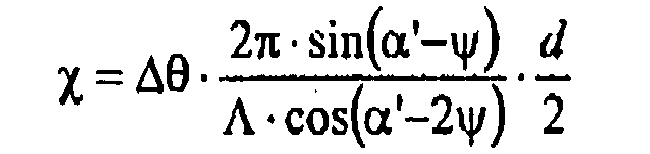


![]()

With: ![]()
Φ ist die Gitterstärke,x ist der Detuning Parameter und ψ der Kippwinkel des Brechungsindexgitters, das geschrieben wurde. α' und β' entsprechen den Winkeln α und β beim Schreiben des Hologramms, aber im Medium. ΔΘ ist das Winkeldetuning gemessen im Medium, also die Abweichung vom Winkel α'. ΔΩ ist das Winkeldetuning gemessen außerhalb des Mediums, also die Abweichung vom Winkel α. n ist der mittlere Brechungsindex des Photopolymers und wurde zu 1.504 gesetzt.Φ is the grating strength, x is the detuning parameter, and ψ is the tilt angle of the refractive index grating that was written. α 'and β' correspond to the angles α and β when writing the hologram, but in the medium. ΔΘ is the angle measurement measured in the medium, ie the deviation from the angle α '. ΔΩ is the angular measurement measured outside the medium, ie the deviation from the angle α. n is the average refractive index of the photopolymer and was set to 1,504.
Die maximale Beugungseffizienz (DE = ηnax) ergibt sich dann für χ = 0, also ΔΩ = 0 zu: 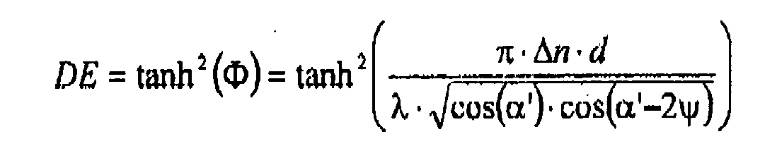
Die Mossdaten der Beugungseffizienz, die theoretische Braggkurve und die transmittierte Intensität werden wie in
Da DE bekannt ist wird die Form der theoretischen Braggkurve nach Kogelnik nur noch durch die Dicke d der Photopolymerschicht bestimmt. Δn wird über DE für gegebene Dicke d so nachkorrigiert, dass Messung und Theorie von DE immer übereinstimmen. d wird nun solange angepasst bis die Winkelpositionen der ersten Nebenminima der theoretischen Braggkurve mit den Winkelpositionen der ersten Nebenmaxima der transmittierten Intensität übereinstimmen und zudem die volle Breite bei halber Höhe (FWHM) für theoretische Braggkurve und die transmittierte Intensität übereinstimmen.Since DE is known, the shape of the theoretical Bragg curve according to Kogelnik is determined only by the thickness d of the photopolymer layer. Δn is corrected over DE for a given thickness d so that the measurement and theory of DE are always the same. d is now adjusted until the angular positions of the first secondary minima of the theoretical Bragg curve coincide with the angular positions of the first secondary maxima of the transmitted intensity and, moreover, the full width at half height (FWHM) for the theoretical Bragg curve and the transmitted intensity coincide.
Da die Richtung in der ein Reflexionshologramm bei der Rekonstruktion mittels eines Ω-Scans mitrotiert, der Detektor für das abgebeugte Licht aber nur einen endlichen Winkelbereich erfassen kann, wird die Braggkurve von breiten Hologrammen (kleines d) bei einem Ω-Scan nicht vollständig erfasst, sondern nur der zentrale Bereich, bei geeigneter Detektorpositionierung. Daher wird die zur Braggkurve komplementäre Form der transmittierten Intensität zur Anpassung der Schichtdicke d zusätzlich herangezogen.Since the direction in which a reflection hologram co-rotates during the reconstruction by means of an Ω scan, but the detector for the diffracted light can detect only a finite angular range, the Bragg curve is not completely detected by wide holograms (small d) in an Ω scan, but only the central area, with suitable detector positioning. Therefore, the complementary to the Bragg curve shape of the transmitted intensity to adjust the layer thickness d is additionally used.
Für eine Formulierung wurde diese Prozedur eventuell mehrfach für verschiedene Belichtungszeiten t an verschiedenen Medien wiederholt, um festzustellen bei welcher mittleren Energiedosis des einfallenden Laserstrahls beim Schreiben des Hologramms DE in den Sättigungswert übergeht. Die mittlere Energiedosis E ergibt sich wie folgt: 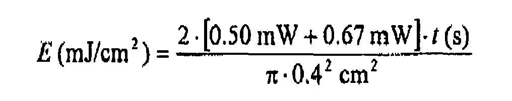
Die Leistungen der Teilstrahlen wurden so angepasst, dass in dem Medium bei den verwendeten Winkeln α und β, die gleiche Leistungsdichte erreicht wird.The powers of the partial beams have been adjusted so that the same power density is achieved in the medium at the angles α and β used.
Alternativ wurde auch ein dem in
Die physikalische Schichtdicke wurde mit marktgängigen Weisslichlinterformetern ermittelt, wie z.B. das Gerät FTM-Lite NIR Schichtdickenmessgerät der Firma Ingenieursbüro Fuchs.The physical layer thickness was determined with commercially available whitish tin formers, e.g. the device FTM-Lite NIR Coating Thickness Gauge from Ingenieursbüro Fuchs.
Die Bestimmung der Schichtdicke beruht im Prinzip auf Interferenzerscheinungen an dünnen Schichten. Dabei überlagern sich Lichtwellen, die an zwei Grenzflächen unterschiedlicher optischer Dichte reflektiert worden sind. Die ungestörte Überlagerung der reflektierten Teilstrahlen führt nun zur periodischen Aufhellung und Auslöschung im Spektrum eines weißen Kontinuumstrahlers (z.B. Halogenlampe). Diese Überlagerung nennt der Fachmann Interferenz. Diese Interferenzspektren werden gemessen und mathematisch ausgewertet.The determination of the layer thickness is based in principle on interference phenomena on thin layers. In the process, light waves are superimposed, which have been reflected at two interfaces of different optical density. The undisturbed superimposition of the reflected partial beams now leads to the periodic brightening and extinction in the spectrum of a white continuum radiator (eg halogen lamp). This superposition is called the expert interference. These interference spectra are measured and evaluated mathematically.
In einem 500 mL Rundkolben wurden 0.1 g 2,6-Di-tert.-butyl-4-methylphenol, 0.05 g Dibutylzinndilaurat (Desmorapid Z, Bayer MaterialScience AG, Leverkusen, Deutschland) sowie und 213.07 g einer 27 %-igen Lösung von Tris(p-isocyanatophenyl)thiophosphat in Ethylacetat (Desmodur® RFE, Produkt der Bayer MaterialScience AG, Leverkusen, Deutschland) vorgelegt und auf 60 °C erwärmt. Anschließend wurden 42.37 g 2-Hydroxyethylacrylat zugetropft und die Mischung weiter auf 60 °C gehalten, bis der Isocyanatgehalt unter 0.1 % gesunken war. Danach wurde abgekühlt und im Vakuum das Ethylacetat vollständig entfernt. Das Produkt wurde als teilkristalliner Feststoff erhalten.In a 500 mL round bottom flask, 0.1 g of 2,6-di-tert-butyl-4-methylphenol, 0.05 g of dibutyltin dilaurate (Desmorapid Z, Bayer MaterialScience AG, Leverkusen, Germany) and 213.07 g of a 27% solution of Tris (p-isocyanatophenyl) thiophosphate in ethyl acetate (Desmodur® RFE, product of Bayer MaterialScience AG, Leverkusen, Germany) and heated to 60 ° C. Subsequently, 42.37 g of 2-hydroxyethyl acrylate were added dropwise and the mixture was kept at 60 ° C until the isocyanate content had dropped below 0.1%. It was then cooled and the ethyl acetate was completely removed in vacuo. The product was obtained as a partially crystalline solid.
10,222 g Polyol l (Komponente B) wurden schrittweise mit 5,00 g Urethanacrylat I (Komponente C), dann 0,100 g Fomrez® UL 28 (Komponente F) und 0,060 g Byk 310 (Komponente G), und zuletzt einer Lösung von 0,300 g CGI 909, 0.010 g Neu Methylenblau, 0,010 g Ethylviolett und 0,010 g Astrazon Orange G (zusammen Komponente E) in 0,610 g N-Ethylpyrilidon (Komponente G) im Dunkeln versetzt und gemischt, so dass eine klare Lösung erhalten wurde. Anschließend wurden bei 30 °C 3,678 g Desmodur® XP 2599 (Komponente A) zugegeben und erneut gemischt. Die erhaltene, flüssige Masse wurde dann mit einem automatisch angetriebenen Filmziehrakel mit einer Ziehgeschwindigkeit von 3 mm/Sekunde und einem Rakelspalt von 50 µm auf eine 175 µm dicke Polyearbonatfolie appliziert und 4,5 Minuten bei 80°C getrocknet. Trockenschichtdicke: 30µm, maximaler Δn: 0,012 (633 nm)10.222 g l polyol (component B) were successively with 5.00 g of urethane acrylate I (component C), then 0.100 g of Fomrez UL 28 ® (component F) and 0.060 g of Byk 310 (component G), and finally a solution of 0.300 g CGI 909, 0.010 g New methylene blue, 0.010 g ethyl violet and 0.010 g Astrazon Orange G (together Component E) in 0.610 g N-ethyl pyrilidone (Component G) were added in the dark and mixed to give a clear solution. 3.678 g of Desmodur ® XP were then 2599 (component A) was added and mixed again at 30 ° C. The resulting liquid composition was then applied to a 175 μm thick polycarbonate sheet by means of an automatically driven film doctor blade with a drawing speed of 3 mm / second and a doctor gap of 50 μm and dried at 80 ° C. for 4.5 minutes. Dry film thickness: 30 μm, maximum Δn: 0.012 (633 nm)
Zur erfindungsgemäßen kontinuierlichen Herstellung der holografischen Folienmaterialien werden die Komponente C, die Komponente D (die bereits in der Komponente C vorgelöst sein kann) sowie gegebenenfalls die Komponente G und F in der Komponente B gegebenenfalls bei 60 °C gelöst und gründlich gemischt. Danach wird im Dunklen oder unter geeigneter Beleuchtung die Komponente E in reiner Form oder in verdünnter Lösung in NEP zugewogen und erneut gemischt. Gegebenenfalls wird maximal 10 Minuten im Trockenschrank auf 60 °C erhitzt. Die erhaltene Mischung kann unter Rühren bei < 10 mbar entgast werden.For the continuous production of the holographic film materials according to the invention, component C, component D (which may already be pre-dissolved in component C) and optionally component G and F in component B are optionally dissolved at 60.degree. C. and mixed thoroughly. Thereafter, in the dark or under suitable illumination, the component E is weighed in pure form or in dilute solution in NEP and mixed again. If necessary, it is heated to 60 ° C. in the drying oven for a maximum of 10 minutes. The resulting mixture can be degassed with stirring at <10 mbar.
Die Komponente A kann ebenfalls unter Rühren bei < 10 mbar entgast werden. Anschließend werden beide Formulierungen mittels Zwangsdosierpumpen über einen der oben genannten Mischverfahren kontinuierlich dosiert und vermischt. Danach wird die Mischung über eine Applikationseinheit, wie z.B. ein Rakel oder eine Schlitzdüse kontinuierlich und homogen auf ein Substrat appliziert.The component A can also be degassed with stirring at <10 mbar. Subsequently, both formulations are metered by means of forced metering via one of the above mixing methods continuously and mixed. Thereafter, the mixture is continuously and homogeneously applied to a substrate via an application unit, such as a doctor blade or a slot die.
Die beschichteten Substrate werden bei ca. 80°C getrocknet und anschließend mit einer der oben genannten Abdeckschichten abgedeckt und in einer lichtdichten Verpackung verpackt.The coated substrates are dried at about 80 ° C and then covered with one of the above cover layers and packaged in a light-tight packaging.
Die Dicke d der Photopolymerschicht ergibt sich aus den dem Fachmann bekannten Beschichtungsparametern der entsprechenden Beschichtungseinrichtung.The thickness d of the photopolymer layer results from the coating parameters known to the person skilled in the art of the corresponding coating device.
Die folgenden Beispiele sind zur Erläuterung der erfindungsgemäßen Methode genannt, sollen aber nicht als begrenzend verstanden sein. Sofern nicht abweichend vermerkt beziehen sich alle Prozentangaben der Photopolymere auf Gewichtsprozent.The following examples are given to illustrate the method of the invention, but should not be construed as limiting. Unless otherwise noted, all percentages of the photopolymers are by weight.
27,83 g Polyol 1 (Komponente B) wurden schrittweise mit 13,75 g Urethanacrylat 1 (Komponente C), dann 0.275 g Fomrez® UL 28 (Komponente F) und 0,165 g Byk 310 (Komponente G), und zuletzt einer Lösung von 0,825 g CGI 909, 0.028 g Neu Methylenblau, 0,028 g Ethylviolett und 0,028 g Astrazon Orange G (zusammen Komponente E) in 1,678 g N-Ethylpyrilidon (Komponente G) im Dunkeln versetzt und gemischt, so dass eine klare Lösung erhalten wurde. Anschließend wurden bei 30 °C 10,395 g Desmodur® XP 2599 (Komponente A) zugegeben und erneut gemischt. Die erhaltene, flüssige Masse wurde dann auf eine 175 µm dicke Polycarbonatfolie appliziert und 4,5 Minuten bei 80°C getrocknet. Trockensehichtdicke: 45µm, maximaler Δn: 0,016 (633 nm); 0,017 (532 nm).27.83 g Polyol 1 (component B) were gradually with 13.75 g of urethane acrylate 1 (component C), then 0.275 g of Fomrez UL 28 ® (component F) and 0.165 g of Byk 310 (component G), and finally a solution of 0.825 g of CGI 909, 0.028 g of New Methylene Blue, 0.028 g of ethyl violet and 0.028 g of Astrazon Orange G (together Component E) in 1.678 g of N-ethylpyrilidone (Component G) were added in the dark and mixed to give a clear solution. 10,395 g Desmodur ® XP were then 2599 (component A) was added and mixed again at 30 ° C. The resulting liquid mass was then applied to a 175 micron thick polycarbonate film and dried at 80 ° C for 4.5 minutes. Dry film thickness: 45 μm, maximum Δn: 0.016 (633 nm); 0.017 (532 nm).
10,245 g Polyol 2 (Komponente B) wurden schrittweise mit 5,00 g Urethanacrylat 1 (Komponente C), dann 0,100 g Fomrez® UL 28 (Komponente F) und 0,060 g Byk 310 (Komponente G), und zuletzt einer Lösung von 0,300 g CGI 909, 0.010 g Neu Methylenblau, 0,010 g Ethylviolett und 0,010 g Astrazon Orange G (zusammen Komponente E) in 0,610 g N-Ethylpyrilidon (Komponente G) im Dunkeln versetzt und gemischt, so dass eine klare Lösung erhalten wurde. Anschließend wurden bei 30 °C 3,655 g Desmodur® XP 2599 (Komponente A) zugegeben und erneut gemischt. Die erhaltene, flüssige Masse wurde dann auf eine 175 µm dicke Polycarbonatfolie appliziert und 4,5 Minuten bei 80°C getrocknet. Trockenschichtdicke: 25 µm, maximaler Δn: 0,012 (633 nm); 0,0 10 (532 nm).10.245 g of Polyol 2 (component B) were successively with 5.00 g of urethane acrylate 1 (component C), then 0.100 g of Fomrez UL 28 ® (component F) and 0.060 g of Byk 310 (component G), and finally a solution of 0.300 g CGI 909, 0.010 g New methylene blue, 0.010 g ethyl violet and 0.010 g Astrazon Orange G (together Component E) in 0.610 g N-ethyl pyrilidone (Component G) were added in the dark and mixed to give a clear solution. 3,655 g Desmodur ® XP were then 2599 (component A) was added and mixed again at 30 ° C. The resulting liquid mass was then applied to a 175 micron thick polycarbonate film and dried at 80 ° C for 4.5 minutes. Dry film thickness: 25 μm, maximum Δn: 0.012 (633 nm); 0.010 (532 nm).
19,946 g Polyol 3 (Komponente B) wurden schrittweise mit 13,75 g Urethanacrylat 1 (Komponente C), dann 0.275 g Fomrez® UL 28 (Komponente F) und 0,165 g Byk 310 (Komponente G), und zuletzt einer Lösung von 0,825 g CGI 909, 0.028 g Neu Methylenblau, 0,028 g Ethylviolett und 0,028 g Astrazon Orange G (zusammen Komponente E) in 1,678 g N-Ethylpyrilidon (Komponente G) im Dunkeln versetzt und gemischt, so dass eine klare Lösung erhalten wurde. Anschließend wurde bei 30 °C eine Mischung aus 6,467 g Desmodur® XP 2599 und 11,812 g Präpolymer 1 (zusammen Komponente A) zugegeben und erneut gemischt. Die erhaltene, flüssige Masse wurde dann auf eine 175 µm dicke Polycarbonatfolie appliziert und 4,5 Minuten bei 80°C getrocknet. Trockenschichtdicke: 32µm, maximaler An: 0,016 (633 nm); 0,0 l7 (532 nm).19.946 g Polyol 3 (component B) were gradually with 13.75 g of urethane acrylate 1 (component C), then 0.275 g of Fomrez UL 28 ® (component F) and 0.165 g of Byk 310 (component G), and finally a solution of 0.825 g CGI 909, 0.028 g New Methylene Blue, 0.028 g Ethyl Violet and 0.028 g of Astrazon Orange G (together Component E) in 1.678 g of N-ethylpyrilidone (Component G) was added in the dark and mixed to give a clear solution. A mixture of 6.467 g of Desmodur ® XP 2599 and 11.812 g of
8,432 g Polyol 3 (Komponente B) wurden schrittweise mit 5,00 g Urethanacrylat 1 (Komponente C), dann 0,100 g Fomrez® UL 28 (Komponente F) und 0,060 g Byk 310 (Komponente G), und zuletzt einer Lösung von 0,300 g CGI 909, 0.010 g Neu Methylenblau, 0,010 g Ethylviolett und 0,010 g Astrazon Orange G (zusammen Komponente E) in 0,610 g N-Ethylpyrilidon (Komponente G) im Dunkeln versetzt und gemischt, so dass eine klare Lösung erhalten wurde. Anschließend wurden bei 30 °C 5,468 g Desmodur® XP 2599 (Komponente A) zugegeben und erneut gemischt. Die erhaltene, flüssige Masse wurde dann auf eine 36 µm dicke Polyothylenterophthalatfolie appliziert und 4,5 Minuten bei 80°C getrocknet. Trockenschichtdicke: 30µm, maximaler Δn: 0,013 (633 nm); 0,014 (532 nm).8,432 g of Polyol 3 (component B) were successively with 5.00 g of urethane acrylate 1 (component C), then 0.100 g of Fomrez UL 28 ® (component F) and 0.060 g of Byk 310 (component G), and finally a solution of 0.300 g CGI 909, 0.010 g New methylene blue, 0.010 g ethyl violet and 0.010 g Astrazon Orange G (together Component E) in 0.610 g N-ethyl pyrilidone (Component G) were added in the dark and mixed to give a clear solution. 5,468 g Desmodur ® XP were then 2599 (component A) was added and mixed again at 30 ° C. The resulting liquid mass was then applied to a 36 μm thick Polyothylenterophthalatfolie and dried at 80 ° C for 4.5 minutes. Dry film thickness: 30 μm, maximum Δn: 0.013 (633 nm); 0.014 (532 nm).
Wie in
Claims (13)
Priority Applications (11)
| Application Number | Priority Date | Filing Date | Title |
|---|---|---|---|
| EP09001952A EP2218744A1 (en) | 2009-02-12 | 2009-02-12 | Method of manufacturing holographic photopolymers on polymer films |
| PL10702439T PL2396358T3 (en) | 2009-02-12 | 2010-01-30 | Method for producing holographic photopolymers on polymer films |
| KR1020117018682A KR20110118785A (en) | 2009-02-12 | 2010-01-30 | Method for producing holographic photopolymer on polymer film |
| SG2011049616A SG172900A1 (en) | 2009-02-12 | 2010-01-30 | Method for producing holographic photopolymers on polymer films |
| ES10702439T ES2400346T3 (en) | 2009-02-12 | 2010-01-30 | Procedure for the manufacture of holographic photopolymers on polymer sheets |
| CN201080007532.8A CN102317337B (en) | 2009-02-12 | 2010-01-30 | Method for preparing holographic photopolymer on polymer film |
| US13/148,694 US8715888B2 (en) | 2009-02-12 | 2010-01-30 | Method for producing holographic photopolymers on polymer films |
| EP10702439A EP2396358B1 (en) | 2009-02-12 | 2010-01-30 | Method for producing holographic photopolymers on polymer films |
| JP2011549462A JP2012517512A (en) | 2009-02-12 | 2010-01-30 | Method for producing holographic photosensitive polymer on polymer film |
| PCT/EP2010/000565 WO2010091795A1 (en) | 2009-02-12 | 2010-01-30 | Method for producing holographic photopolymers on polymer films |
| TW099104259A TWI494357B (en) | 2009-02-12 | 2010-02-11 | Method for the preparation of holographic photopolymers on polymer films |
Applications Claiming Priority (1)
| Application Number | Priority Date | Filing Date | Title |
|---|---|---|---|
| EP09001952A EP2218744A1 (en) | 2009-02-12 | 2009-02-12 | Method of manufacturing holographic photopolymers on polymer films |
Publications (1)
| Publication Number | Publication Date |
|---|---|
| EP2218744A1 true EP2218744A1 (en) | 2010-08-18 |
Family
ID=40908532
Family Applications (2)
| Application Number | Title | Priority Date | Filing Date |
|---|---|---|---|
| EP09001952A Withdrawn EP2218744A1 (en) | 2009-02-12 | 2009-02-12 | Method of manufacturing holographic photopolymers on polymer films |
| EP10702439A Active EP2396358B1 (en) | 2009-02-12 | 2010-01-30 | Method for producing holographic photopolymers on polymer films |
Family Applications After (1)
| Application Number | Title | Priority Date | Filing Date |
|---|---|---|---|
| EP10702439A Active EP2396358B1 (en) | 2009-02-12 | 2010-01-30 | Method for producing holographic photopolymers on polymer films |
Country Status (10)
| Country | Link |
|---|---|
| US (1) | US8715888B2 (en) |
| EP (2) | EP2218744A1 (en) |
| JP (1) | JP2012517512A (en) |
| KR (1) | KR20110118785A (en) |
| CN (1) | CN102317337B (en) |
| ES (1) | ES2400346T3 (en) |
| PL (1) | PL2396358T3 (en) |
| SG (1) | SG172900A1 (en) |
| TW (1) | TWI494357B (en) |
| WO (1) | WO2010091795A1 (en) |
Cited By (4)
| Publication number | Priority date | Publication date | Assignee | Title |
|---|---|---|---|---|
| EP2450387A1 (en) | 2010-11-08 | 2012-05-09 | Bayer MaterialScience AG | Photopolymer formulation for producing holographic media |
| US8771904B2 (en) | 2009-11-03 | 2014-07-08 | Bayer Materialscience Ag | Method for producing holographic media |
| US8889321B2 (en) | 2009-11-03 | 2014-11-18 | Bayer Materialscience Ag | Method for producing a holographic film |
| WO2016016426A1 (en) * | 2014-08-01 | 2016-02-04 | Covestro Deutschland Ag | Layer structure comprising a photopolymer layer and a substrate layer |
Families Citing this family (19)
| Publication number | Priority date | Publication date | Assignee | Title |
|---|---|---|---|---|
| US8852829B2 (en) * | 2008-10-01 | 2014-10-07 | Bayer Materialscience Ag | Prepolymer-based polyurethane formulations for producing holographic media |
| WO2010037515A1 (en) * | 2008-10-01 | 2010-04-08 | Bayer Materialscience Ag | Media for volume-holographic recording based on self-developing polymer |
| EP2218742A1 (en) * | 2009-02-12 | 2010-08-18 | Bayer MaterialScience AG | Photopolymer compounds as compressible formulations |
| EP2218743A1 (en) * | 2009-02-12 | 2010-08-18 | Bayer MaterialScience AG | Prepolymer-based polyurethane formulations for producing holographic films |
| ATE548730T1 (en) * | 2009-11-03 | 2012-03-15 | Bayer Materialscience Ag | PHOTOPOLYMER FORMULATIONS WITH ADJUSTABLE MECHANICAL MODULE GUV |
| US8771903B2 (en) * | 2009-11-03 | 2014-07-08 | Bayer Materialscience Ag | Method for producing a holographic film |
| EP2497083B1 (en) * | 2009-11-03 | 2013-12-25 | Bayer Intellectual Property GmbH | Photopolymer formulation with various comonomers |
| US20140302425A1 (en) * | 2012-04-30 | 2014-10-09 | Bayer Intellectual Property Gmbh | Method for producing holographic media |
| JP6437435B2 (en) | 2012-08-13 | 2018-12-12 | コベストロ、ドイチュラント、アクチエンゲゼルシャフトCovestro Deutschland Ag | Light guide plate having output coupling element |
| CA2883840C (en) | 2012-09-17 | 2021-01-26 | Basf Se | Security elements and method for their manufacture |
| EP3540521B1 (en) * | 2016-11-30 | 2022-01-05 | LG Chem, Ltd. | Hologram reproduction method and device |
| CN107610722B (en) * | 2017-08-21 | 2019-06-25 | 沈阳航空航天大学 | It is a kind of based on polycarbonate be substrate photo polymerization holographic material and preparation method thereof |
| KR102033957B1 (en) * | 2018-05-23 | 2019-10-18 | (주)케이피엘솔루션 | UV Curable Liquid Resin composition for Printing Plate Having Improved Resolution and the Making Method thereof |
| ES2955365T3 (en) | 2021-02-11 | 2023-11-30 | Xetos Ag | Light-curing composition |
| EP4043963B1 (en) | 2021-02-11 | 2023-07-05 | Xetos AG | Improved bleaching |
| EP4043502B1 (en) | 2021-02-11 | 2023-10-04 | Xetos AG | Photopolymerizable hoe composition |
| EP4043961B1 (en) | 2021-02-11 | 2023-08-16 | Xetos AG | 2k system |
| DE102022120870A1 (en) * | 2022-08-18 | 2024-02-29 | Carl Zeiss Jena Gmbh | REPLICATION PROCESS FOR COPYING HOLOGRAMS INTO LIQUID PHOTOPOLYMERS |
| DE102022120865A1 (en) * | 2022-08-18 | 2024-02-29 | Carl Zeiss Jena Gmbh | REPLICATION DEVICE FOR COPYING HOLOGRAMS INTO LIQUID PHOTOPOLYMERS |
Citations (3)
| Publication number | Priority date | Publication date | Assignee | Title |
|---|---|---|---|---|
| DE19754024A1 (en) * | 1997-12-05 | 1999-06-10 | Basf Ag | Rotating roller continuously coating sheet material with polyurethane precursor |
| JP2001187362A (en) * | 1999-12-28 | 2001-07-10 | Mitsui Chemicals Inc | Continuous coating method of thermosetting polyurethane and method of manufacturing thermosetting polyurethane sheet |
| WO2008125199A1 (en) * | 2007-04-11 | 2008-10-23 | Bayer Materialscience Ag | Aromatic urethane acrylates having a high refractive index |
Family Cites Families (22)
| Publication number | Priority date | Publication date | Assignee | Title |
|---|---|---|---|---|
| US3667946A (en) * | 1970-09-23 | 1972-06-06 | Holotron Corp | Surface treatment of photopolymer film used for recording holograms |
| DE3822093C2 (en) * | 1987-06-30 | 1997-11-06 | Fuji Photo Film Co Ltd | Process for degassing and defoaming a photosensitive coating solution and apparatus for carrying out this process |
| US5083219A (en) * | 1989-12-26 | 1992-01-21 | Physical Optics Corporation | Method and apparatus for recording lippman holographic mirrors |
| US5565982A (en) | 1994-05-31 | 1996-10-15 | Recon Exploration | Apparatus and method for time resolved spectroscopy |
| US6344495B1 (en) * | 1998-07-31 | 2002-02-05 | Dai Nippon Printing Co., Ltd. | Photo-curable resin composition and method for forming concave-convex pattern |
| EP2309339B1 (en) * | 1999-01-19 | 2016-11-30 | Dai Nippon Printing Co., Ltd. | Relief hologram or diffraction grating sheet and forgery-preventing sheet comprising the same |
| US6414761B1 (en) * | 2000-03-06 | 2002-07-02 | Illinois Tool Works Inc. | Secure holographic images on paper |
| US6743552B2 (en) * | 2001-08-07 | 2004-06-01 | Inphase Technologies, Inc. | Process and composition for rapid mass production of holographic recording article |
| WO2003084728A1 (en) * | 2002-04-08 | 2003-10-16 | Hoya Corporation | Process for producing optical member, process for producing plastic lens, gasket for plastic lens molding, and jig for monomer injection |
| JP4466140B2 (en) * | 2003-11-27 | 2010-05-26 | コニカミノルタエムジー株式会社 | Holographic recording medium, holographic recording method, and holographic information medium |
| DE102004015983A1 (en) * | 2004-04-01 | 2005-10-20 | Bayer Materialscience Ag | Process for the preparation of polyether allophanates using zinc compounds as catalysts |
| WO2006120887A1 (en) * | 2005-05-12 | 2006-11-16 | Nippon Kayaku Kabushiki Kaisha | Photosensitive resin compositions, cured articles of the compositions, and films containing the compositions |
| US7678507B2 (en) * | 2006-01-18 | 2010-03-16 | Inphase Technologies, Inc. | Latent holographic media and method |
| CN101174090A (en) * | 2006-11-02 | 2008-05-07 | 乐凯集团第二胶片厂 | Photopolymerizable lithographic printing plate |
| KR101451265B1 (en) * | 2007-02-05 | 2014-10-15 | 신닛테츠 수미킨 가가쿠 가부시키가이샤 | Volume phase hologram recording material and optical information recording medium |
| IL200997A0 (en) * | 2008-10-01 | 2010-06-30 | Bayer Materialscience Ag | Special polyether-based polyurethane formulations for the production of holographic media |
| IL200722A0 (en) | 2008-10-01 | 2010-06-30 | Bayer Materialscience Ag | Photopolymer compositions for optical elements and visual displays |
| WO2010037515A1 (en) | 2008-10-01 | 2010-04-08 | Bayer Materialscience Ag | Media for volume-holographic recording based on self-developing polymer |
| US8852829B2 (en) * | 2008-10-01 | 2014-10-07 | Bayer Materialscience Ag | Prepolymer-based polyurethane formulations for producing holographic media |
| IL200995A0 (en) | 2008-10-01 | 2010-06-30 | Bayer Materialscience Ag | Polyether-based polyurethane formulations for the production of holographic media |
| EP2218743A1 (en) * | 2009-02-12 | 2010-08-18 | Bayer MaterialScience AG | Prepolymer-based polyurethane formulations for producing holographic films |
| EP2218742A1 (en) * | 2009-02-12 | 2010-08-18 | Bayer MaterialScience AG | Photopolymer compounds as compressible formulations |
-
2009
- 2009-02-12 EP EP09001952A patent/EP2218744A1/en not_active Withdrawn
-
2010
- 2010-01-30 PL PL10702439T patent/PL2396358T3/en unknown
- 2010-01-30 CN CN201080007532.8A patent/CN102317337B/en not_active Expired - Fee Related
- 2010-01-30 KR KR1020117018682A patent/KR20110118785A/en not_active Withdrawn
- 2010-01-30 JP JP2011549462A patent/JP2012517512A/en active Pending
- 2010-01-30 EP EP10702439A patent/EP2396358B1/en active Active
- 2010-01-30 US US13/148,694 patent/US8715888B2/en active Active
- 2010-01-30 ES ES10702439T patent/ES2400346T3/en active Active
- 2010-01-30 WO PCT/EP2010/000565 patent/WO2010091795A1/en not_active Ceased
- 2010-01-30 SG SG2011049616A patent/SG172900A1/en unknown
- 2010-02-11 TW TW099104259A patent/TWI494357B/en not_active IP Right Cessation
Patent Citations (3)
| Publication number | Priority date | Publication date | Assignee | Title |
|---|---|---|---|---|
| DE19754024A1 (en) * | 1997-12-05 | 1999-06-10 | Basf Ag | Rotating roller continuously coating sheet material with polyurethane precursor |
| JP2001187362A (en) * | 1999-12-28 | 2001-07-10 | Mitsui Chemicals Inc | Continuous coating method of thermosetting polyurethane and method of manufacturing thermosetting polyurethane sheet |
| WO2008125199A1 (en) * | 2007-04-11 | 2008-10-23 | Bayer Materialscience Ag | Aromatic urethane acrylates having a high refractive index |
Non-Patent Citations (3)
| Title |
|---|
| H. KOGELNIK, THE BELL SYSTEM TECHNICAL JOURNAL, vol. 48, no. 9, November 1969 (1969-11-01), pages 2909 - 2947 |
| M. SCHMALZ; N. HANSEN; W. NEUMANN: "5- oder 6-Walzen ßeschichtungsverfahren", COATING, October 2006 (2006-10-01), pages 410 - 413 |
| P. M- SCHWEIZER: "Vordosierte Beschichtungsverfahren: Vorzüge und Anwendungen", COATING, December 1998 (1998-12-01), pages 462 - 465 |
Cited By (6)
| Publication number | Priority date | Publication date | Assignee | Title |
|---|---|---|---|---|
| US8771904B2 (en) | 2009-11-03 | 2014-07-08 | Bayer Materialscience Ag | Method for producing holographic media |
| US8889321B2 (en) | 2009-11-03 | 2014-11-18 | Bayer Materialscience Ag | Method for producing a holographic film |
| EP2450387A1 (en) | 2010-11-08 | 2012-05-09 | Bayer MaterialScience AG | Photopolymer formulation for producing holographic media |
| WO2012062658A1 (en) | 2010-11-08 | 2012-05-18 | Bayer Materialscience Ag | Photopolymer formulation for producing holographic media |
| US9098065B2 (en) | 2010-11-08 | 2015-08-04 | Bayer Intellectual Property Gmbh | Photopolymer formulation for producing holographic media |
| WO2016016426A1 (en) * | 2014-08-01 | 2016-02-04 | Covestro Deutschland Ag | Layer structure comprising a photopolymer layer and a substrate layer |
Also Published As
| Publication number | Publication date |
|---|---|
| JP2012517512A (en) | 2012-08-02 |
| CN102317337B (en) | 2014-11-26 |
| US20110311905A1 (en) | 2011-12-22 |
| CN102317337A (en) | 2012-01-11 |
| WO2010091795A1 (en) | 2010-08-19 |
| ES2400346T3 (en) | 2013-04-09 |
| WO2010091795A8 (en) | 2011-06-23 |
| TW201035190A (en) | 2010-10-01 |
| TWI494357B (en) | 2015-08-01 |
| US8715888B2 (en) | 2014-05-06 |
| PL2396358T3 (en) | 2013-05-31 |
| SG172900A1 (en) | 2011-08-29 |
| EP2396358A1 (en) | 2011-12-21 |
| KR20110118785A (en) | 2011-11-01 |
| EP2396358B1 (en) | 2013-01-23 |
Similar Documents
| Publication | Publication Date | Title |
|---|---|---|
| EP2396358B1 (en) | Method for producing holographic photopolymers on polymer films | |
| EP2218745B1 (en) | Prepolymer-based polyurethane formulations for producing holographic films | |
| EP2497085B1 (en) | Method for producing a holographic film | |
| EP2396359B1 (en) | Photopolymer compounds as compressible formulations | |
| EP2497080B1 (en) | Method for producing a holographic film | |
| EP2497081B1 (en) | Method for producing holographic media | |
| EP2638089B1 (en) | Photopolymer formulation for producing holographic media | |
| EP2531889B1 (en) | Use of a photopolymer formulation with ester-based writing monomers for the fabrication of holographic media | |
| EP2372454A1 (en) | Photopolymer formulation for producing visible holograms | |
| EP2354845B1 (en) | Photopolymer Composition for the Manufacturing of Holographic Media | |
| WO2010037515A1 (en) | Media for volume-holographic recording based on self-developing polymer | |
| EP3063762B1 (en) | Composite comprising a substrate and a photopolymer film | |
| EP3175297A1 (en) | Layer structure comprising a photopolymer layer and a substrate layer | |
| EP4584335A1 (en) | Specific benzopyrylium salts as dyestuffs for photopolymer compositions |
Legal Events
| Date | Code | Title | Description |
|---|---|---|---|
| PUAI | Public reference made under article 153(3) epc to a published international application that has entered the european phase |
Free format text: ORIGINAL CODE: 0009012 |
|
| AK | Designated contracting states |
Kind code of ref document: A1 Designated state(s): AT BE BG CH CY CZ DE DK EE ES FI FR GB GR HR HU IE IS IT LI LT LU LV MC MK MT NL NO PL PT RO SE SI SK TR |
|
| AX | Request for extension of the european patent |
Extension state: AL BA RS |
|
| STAA | Information on the status of an ep patent application or granted ep patent |
Free format text: STATUS: THE APPLICATION HAS BEEN WITHDRAWN |
|
| 18W | Application withdrawn |
Effective date: 20100903 |