EP2180474A1 - Optical data recording medium and manufacturing method for the same, and a method for clamping the optical data recording medium - Google Patents
Optical data recording medium and manufacturing method for the same, and a method for clamping the optical data recording medium Download PDFInfo
- Publication number
- EP2180474A1 EP2180474A1 EP10151148A EP10151148A EP2180474A1 EP 2180474 A1 EP2180474 A1 EP 2180474A1 EP 10151148 A EP10151148 A EP 10151148A EP 10151148 A EP10151148 A EP 10151148A EP 2180474 A1 EP2180474 A1 EP 2180474A1
- Authority
- EP
- European Patent Office
- Prior art keywords
- protrusion
- recording medium
- optical data
- data recording
- transparent protective
- Prior art date
- Legal status (The legal status is an assumption and is not a legal conclusion. Google has not performed a legal analysis and makes no representation as to the accuracy of the status listed.)
- Withdrawn
Links
- 230000003287 optical effect Effects 0.000 title claims abstract description 240
- 238000004519 manufacturing process Methods 0.000 title claims description 44
- 238000000034 method Methods 0.000 title claims description 39
- 239000011241 protective layer Substances 0.000 claims abstract description 148
- 239000010410 layer Substances 0.000 claims abstract description 126
- 238000012546 transfer Methods 0.000 claims description 5
- 229920005989 resin Polymers 0.000 description 43
- 239000011347 resin Substances 0.000 description 43
- 239000000758 substrate Substances 0.000 description 30
- 238000006748 scratching Methods 0.000 description 12
- 230000002393 scratching effect Effects 0.000 description 12
- 239000000463 material Substances 0.000 description 11
- JCTJISIFGZHOFY-UHFFFAOYSA-N 2-(4,6-dichloro-2-methyl-1h-indol-3-yl)ethanamine Chemical compound ClC1=CC(Cl)=C2C(CCN)=C(C)NC2=C1 JCTJISIFGZHOFY-UHFFFAOYSA-N 0.000 description 10
- 239000000853 adhesive Substances 0.000 description 7
- 230000001070 adhesive effect Effects 0.000 description 7
- 239000010408 film Substances 0.000 description 7
- 239000007788 liquid Substances 0.000 description 7
- 230000000694 effects Effects 0.000 description 6
- 238000000465 moulding Methods 0.000 description 6
- 229920001187 thermosetting polymer Polymers 0.000 description 6
- 238000001746 injection moulding Methods 0.000 description 5
- 239000011344 liquid material Substances 0.000 description 5
- 239000004820 Pressure-sensitive adhesive Substances 0.000 description 4
- 230000001681 protective effect Effects 0.000 description 4
- 238000007650 screen-printing Methods 0.000 description 4
- 239000004417 polycarbonate Substances 0.000 description 3
- 229920000515 polycarbonate Polymers 0.000 description 3
- 238000005266 casting Methods 0.000 description 2
- 239000011248 coating agent Substances 0.000 description 2
- 238000000576 coating method Methods 0.000 description 2
- 238000013461 design Methods 0.000 description 2
- 230000002452 interceptive effect Effects 0.000 description 2
- 229910052751 metal Inorganic materials 0.000 description 2
- 239000002184 metal Substances 0.000 description 2
- 238000012986 modification Methods 0.000 description 2
- 230000004048 modification Effects 0.000 description 2
- UIFGGABIJBWRMG-FMQUCBEESA-N (4-chlorophenyl)methyl (ne)-n-[(4-chlorophenyl)methoxycarbonylimino]carbamate Chemical compound C1=CC(Cl)=CC=C1COC(=O)\N=N\C(=O)OCC1=CC=C(Cl)C=C1 UIFGGABIJBWRMG-FMQUCBEESA-N 0.000 description 1
- 229910052782 aluminium Inorganic materials 0.000 description 1
- XAGFODPZIPBFFR-UHFFFAOYSA-N aluminium Chemical compound [Al] XAGFODPZIPBFFR-UHFFFAOYSA-N 0.000 description 1
- 238000010276 construction Methods 0.000 description 1
- 238000012937 correction Methods 0.000 description 1
- 238000013500 data storage Methods 0.000 description 1
- 230000007423 decrease Effects 0.000 description 1
- 238000011161 development Methods 0.000 description 1
- 239000000428 dust Substances 0.000 description 1
- 238000005530 etching Methods 0.000 description 1
- PCHJSUWPFVWCPO-UHFFFAOYSA-N gold Chemical compound [Au] PCHJSUWPFVWCPO-UHFFFAOYSA-N 0.000 description 1
- 239000010931 gold Substances 0.000 description 1
- 229910052737 gold Inorganic materials 0.000 description 1
- 238000003754 machining Methods 0.000 description 1
- 238000005007 materials handling Methods 0.000 description 1
- 229910001092 metal group alloy Inorganic materials 0.000 description 1
- JFNLZVQOOSMTJK-KNVOCYPGSA-N norbornene Chemical compound C1[C@@H]2CC[C@H]1C=C2 JFNLZVQOOSMTJK-KNVOCYPGSA-N 0.000 description 1
- 239000000049 pigment Substances 0.000 description 1
- 239000004033 plastic Substances 0.000 description 1
- 229920005672 polyolefin resin Polymers 0.000 description 1
- 238000003825 pressing Methods 0.000 description 1
- 238000007639 printing Methods 0.000 description 1
- 238000004904 shortening Methods 0.000 description 1
- 229910052710 silicon Inorganic materials 0.000 description 1
- 239000010703 silicon Substances 0.000 description 1
- 239000010409 thin film Substances 0.000 description 1
Images


Classifications
-
- G—PHYSICS
- G11—INFORMATION STORAGE
- G11B—INFORMATION STORAGE BASED ON RELATIVE MOVEMENT BETWEEN RECORD CARRIER AND TRANSDUCER
- G11B7/00—Recording or reproducing by optical means, e.g. recording using a thermal beam of optical radiation by modifying optical properties or the physical structure, reproducing using an optical beam at lower power by sensing optical properties; Record carriers therefor
- G11B7/24—Record carriers characterised by shape, structure or physical properties, or by the selection of the material
- G11B7/24018—Laminated discs
- G11B7/24027—Layers; Shape, structure or physical properties thereof
-
- G—PHYSICS
- G11—INFORMATION STORAGE
- G11B—INFORMATION STORAGE BASED ON RELATIVE MOVEMENT BETWEEN RECORD CARRIER AND TRANSDUCER
- G11B23/00—Record carriers not specific to the method of recording or reproducing; Accessories, e.g. containers, specially adapted for co-operation with the recording or reproducing apparatus ; Intermediate mediums; Apparatus or processes specially adapted for their manufacture
- G11B23/0014—Record carriers not specific to the method of recording or reproducing; Accessories, e.g. containers, specially adapted for co-operation with the recording or reproducing apparatus ; Intermediate mediums; Apparatus or processes specially adapted for their manufacture record carriers not specifically of filamentary or web form
- G11B23/0021—Record carriers not specific to the method of recording or reproducing; Accessories, e.g. containers, specially adapted for co-operation with the recording or reproducing apparatus ; Intermediate mediums; Apparatus or processes specially adapted for their manufacture record carriers not specifically of filamentary or web form discs
- G11B23/0028—Details
- G11B23/0035—Details means incorporated in the disc, e.g. hub, to enable its guiding, loading or driving
-
- B—PERFORMING OPERATIONS; TRANSPORTING
- B29—WORKING OF PLASTICS; WORKING OF SUBSTANCES IN A PLASTIC STATE IN GENERAL
- B29C—SHAPING OR JOINING OF PLASTICS; SHAPING OF MATERIAL IN A PLASTIC STATE, NOT OTHERWISE PROVIDED FOR; AFTER-TREATMENT OF THE SHAPED PRODUCTS, e.g. REPAIRING
- B29C45/00—Injection moulding, i.e. forcing the required volume of moulding material through a nozzle into a closed mould; Apparatus therefor
- B29C45/17—Component parts, details or accessories; Auxiliary operations
- B29C45/26—Moulds
- B29C45/263—Moulds with mould wall parts provided with fine grooves or impressions, e.g. for record discs
-
- B—PERFORMING OPERATIONS; TRANSPORTING
- B29—WORKING OF PLASTICS; WORKING OF SUBSTANCES IN A PLASTIC STATE IN GENERAL
- B29D—PRODUCING PARTICULAR ARTICLES FROM PLASTICS OR FROM SUBSTANCES IN A PLASTIC STATE
- B29D17/00—Producing carriers of records containing fine grooves or impressions, e.g. disc records for needle playback, cylinder records; Producing record discs from master stencils
- B29D17/005—Producing optically read record carriers, e.g. optical discs
-
- G—PHYSICS
- G11—INFORMATION STORAGE
- G11B—INFORMATION STORAGE BASED ON RELATIVE MOVEMENT BETWEEN RECORD CARRIER AND TRANSDUCER
- G11B17/00—Guiding record carriers not specifically of filamentary or web form, or of supports therefor
- G11B17/02—Details
- G11B17/022—Positioning or locking of single discs
- G11B17/028—Positioning or locking of single discs of discs rotating during transducing operation
- G11B17/0284—Positioning or locking of single discs of discs rotating during transducing operation by clampers
-
- G—PHYSICS
- G11—INFORMATION STORAGE
- G11B—INFORMATION STORAGE BASED ON RELATIVE MOVEMENT BETWEEN RECORD CARRIER AND TRANSDUCER
- G11B7/00—Recording or reproducing by optical means, e.g. recording using a thermal beam of optical radiation by modifying optical properties or the physical structure, reproducing using an optical beam at lower power by sensing optical properties; Record carriers therefor
- G11B7/12—Heads, e.g. forming of the optical beam spot or modulation of the optical beam
- G11B7/121—Protecting the head, e.g. against dust or impact with the record carrier
-
- G—PHYSICS
- G11—INFORMATION STORAGE
- G11B—INFORMATION STORAGE BASED ON RELATIVE MOVEMENT BETWEEN RECORD CARRIER AND TRANSDUCER
- G11B7/00—Recording or reproducing by optical means, e.g. recording using a thermal beam of optical radiation by modifying optical properties or the physical structure, reproducing using an optical beam at lower power by sensing optical properties; Record carriers therefor
- G11B7/24—Record carriers characterised by shape, structure or physical properties, or by the selection of the material
- G11B7/24003—Shapes of record carriers other than disc shape
-
- G—PHYSICS
- G11—INFORMATION STORAGE
- G11B—INFORMATION STORAGE BASED ON RELATIVE MOVEMENT BETWEEN RECORD CARRIER AND TRANSDUCER
- G11B7/00—Recording or reproducing by optical means, e.g. recording using a thermal beam of optical radiation by modifying optical properties or the physical structure, reproducing using an optical beam at lower power by sensing optical properties; Record carriers therefor
- G11B7/24—Record carriers characterised by shape, structure or physical properties, or by the selection of the material
- G11B7/24097—Structures for detection, control, recording operation or replay operation; Special shapes or structures for centering or eccentricity prevention; Arrangements for testing, inspecting or evaluating; Containers, cartridges or cassettes
-
- G—PHYSICS
- G11—INFORMATION STORAGE
- G11B—INFORMATION STORAGE BASED ON RELATIVE MOVEMENT BETWEEN RECORD CARRIER AND TRANSDUCER
- G11B7/00—Recording or reproducing by optical means, e.g. recording using a thermal beam of optical radiation by modifying optical properties or the physical structure, reproducing using an optical beam at lower power by sensing optical properties; Record carriers therefor
- G11B7/24—Record carriers characterised by shape, structure or physical properties, or by the selection of the material
- G11B7/26—Apparatus or processes specially adapted for the manufacture of record carriers
-
- B—PERFORMING OPERATIONS; TRANSPORTING
- B29—WORKING OF PLASTICS; WORKING OF SUBSTANCES IN A PLASTIC STATE IN GENERAL
- B29C—SHAPING OR JOINING OF PLASTICS; SHAPING OF MATERIAL IN A PLASTIC STATE, NOT OTHERWISE PROVIDED FOR; AFTER-TREATMENT OF THE SHAPED PRODUCTS, e.g. REPAIRING
- B29C45/00—Injection moulding, i.e. forcing the required volume of moulding material through a nozzle into a closed mould; Apparatus therefor
- B29C45/17—Component parts, details or accessories; Auxiliary operations
- B29C45/26—Moulds
- B29C45/263—Moulds with mould wall parts provided with fine grooves or impressions, e.g. for record discs
- B29C2045/2661—The thickness of the mould cavity being changeable in radial direction
-
- B—PERFORMING OPERATIONS; TRANSPORTING
- B29—WORKING OF PLASTICS; WORKING OF SUBSTANCES IN A PLASTIC STATE IN GENERAL
- B29C—SHAPING OR JOINING OF PLASTICS; SHAPING OF MATERIAL IN A PLASTIC STATE, NOT OTHERWISE PROVIDED FOR; AFTER-TREATMENT OF THE SHAPED PRODUCTS, e.g. REPAIRING
- B29C45/00—Injection moulding, i.e. forcing the required volume of moulding material through a nozzle into a closed mould; Apparatus therefor
- B29C45/17—Component parts, details or accessories; Auxiliary operations
- B29C45/26—Moulds
- B29C45/263—Moulds with mould wall parts provided with fine grooves or impressions, e.g. for record discs
- B29C2045/2667—Particular inner or outer peripheral portions of the substrate
-
- B—PERFORMING OPERATIONS; TRANSPORTING
- B29—WORKING OF PLASTICS; WORKING OF SUBSTANCES IN A PLASTIC STATE IN GENERAL
- B29L—INDEXING SCHEME ASSOCIATED WITH SUBCLASS B29C, RELATING TO PARTICULAR ARTICLES
- B29L2017/00—Carriers for sound or information
- B29L2017/001—Carriers of records containing fine grooves or impressions, e.g. disc records for needle playback, cylinder records
- B29L2017/003—Records or discs
- B29L2017/005—CD''s, DVD''s
-
- G—PHYSICS
- G11—INFORMATION STORAGE
- G11B—INFORMATION STORAGE BASED ON RELATIVE MOVEMENT BETWEEN RECORD CARRIER AND TRANSDUCER
- G11B7/00—Recording or reproducing by optical means, e.g. recording using a thermal beam of optical radiation by modifying optical properties or the physical structure, reproducing using an optical beam at lower power by sensing optical properties; Record carriers therefor
- G11B7/24—Record carriers characterised by shape, structure or physical properties, or by the selection of the material
- G11B7/26—Apparatus or processes specially adapted for the manufacture of record carriers
- G11B7/263—Preparing and using a stamper, e.g. pressing or injection molding substrates
Definitions
- the present invention relates to a disc-shaped optical data recording medium having a signal recording layer for recording and/or playing information by emitting a light beam thereto, and a transparent protective layer 10 ⁇ m to 200 ⁇ m thick disposed over the signal recording layer.
- the invention also relates to a method for manufacturing this optical data recording medium, and to a method for clamping the optical data recording medium.
- Optical discs are known and widely used as a high capacity data storage medium for high density recording and playback of information using a laser beam. These optical discs are broadly categorized as read-only, incrementally writable (multisession), and rewritable. Typical of read-only discs are Compact Discs (CDs) storing audio content and Laser Discs storing video content such as movies. Both incrementally writable (multisession) and rewritable media are widely used in the computer industry, for example, for storing text documents and still image files.
- optical discs typically have a data layer disposed to one main side of a 1.2 mm thick transparent substrate. A protective overcoat is then applied to the data layer, or a protective disc identical to the transparent substrate is bonded by adhesive to the data layer. See, for example, Japanese Laid-Open Patent Publication No. 2001-093193 , paragraph [0015] and Fig. 1 , and Japanese Laid-open Patent Publication No. 2002-042376 , paragraph [0019] and Fig. 1 .
- DVD Digital Versatile Discs
- High density media such as DVD have been achieved by using a shorter wavelength laser and an objective lens with a large numeric aperture (NA).
- NA numeric aperture
- shortening the beam wavelength and increasing the NA also reduce the tolerance for tilt, the inclination of the disc to the direction of laser beam emission.
- Tolerance for tilt can be improved by using a thinner substrate.
- DVD media this means, for example, using a 0.6 mm thick substrate assuming a 650 nm laser and 0.60 NA. Because a 0.6 mm thick substrate is mechanically weak and would thus increase tilt, DVD discs have two such substrates bonded together with the data recording surfaces on the inside between the substrates.
- a transparent reflective layer of gold or silicon is formed on the data recording surface of one of the two substrates, and a conventional reflective layer of aluminum, for example, is formed on the data recording surface of the other substrate.
- the substrates are then bonded together with these data recording surfaces facing each other on the inside, resulting in a single-sided, double-layer DVD that can be read from one side of the disc, that is, from the side of the substrate having the transparent reflective layer over the data recording layer.
- Rewritable DVD media with a similar double-layer construction are also available, but the data recording surface in this case is a rewritable thin-film recording layer instead of a metal mirror layer.
- Using a blue-purple laser with an approximately 400 nm wavelength has also been proposed as a way to achieve even higher recording densities.
- One method uses an approximately 0.1 mm thick transparent protective layer on the read/write side and forms an ultrafine laser spot using an approximately 0.85 NA lens for signal reading and/or writing.
- the transparent layer can be formed with the following two methods.
- a polycarbonate sheet manufactured by casting for example, is used as the transparent substrate. Thickness variation in such cast sheets is minimal at approximately +/- 1 ⁇ m.
- the thickness of the adhesive used to bond this polycarbonate sheet to the signal substrate is also thin and can be easily formed to a uniform thickness. As a result, a transparent protective layer with uniform thickness can be formed on the recording/playback side of the disc.
- a problem with high density optical discs is that the surface of the transparent protective layer is easily scratched, and scratches can easily cause a loss of servo control.
- Increasing the mechanical strength of the transparent protective layer itself increases the film thickness, and is not suited for high density recording. It is therefore difficult to protect the surface from scratching while keeping the transparent protective layer thin.
- the data transfer rate during recording and playback is higher with high density optical discs than conventional CD and DVD media, and the disc therefore spins faster. Imbalances in the shape and weight of the disc relative to the spindle hole can therefore increase the load on the rotating spindle (motor).
- the present invention is therefore directed to solving these three problems, and an object of the invention is to provide an optical data recording medium having surface protrusions for protecting the transparent protective layer and reducing the load on the motor during disc rotation, and enabling higher disc clamping force to be applied to the optical data recording medium.
- an optical data recording medium with a signal recording layer for reading and/or writing data using light, and a 10 ⁇ m to 200 ⁇ m thick transparent protective layer disposed over the signal recording layer comprises a protrusion projecting from the surface of the transparent protective layer on the light-incidence surface side to which light is emitted to the signal recording layer in an area between a center hole and a clamping area where the optical data recording medium is held when reading and/or writing data in the signal recording layer.
- this protrusion is on the inside circumference side of the clamping area, the protrusion will not interfere (collide) with the optical head. Furthermore, when the optical data recording medium is placed on a flat surface with the transparent protective layer side facing the flat surface, the protrusion keeps the transparent protective layer off the flat surface and thereby prevents scratching the transparent protective layer.
- the load imposed on the rotating spindle (motor) caused by a weight imbalance in the protrusion is also reduced because the protrusion is located near the center spindle hole.
- the protrusion is preferably disposed separated at least 0.1 mm in the radial direction from an outside edge of the center hole. This configuration prevents the protrusion from interfering with the center cone used to hold the optical data recording medium at the spindle hole in the disc recording and playback drive, and thereby enables stable camping of the optical data recording medium.
- a disc-shaped optical data recording medium with a signal recording layer for reading and/or writing data using light, and a 10 ⁇ m to 200 ⁇ m thick transparent protective layer disposed over the signal recording layer is characterized by having a clamping area on the outside of the center hole in the radial direction for holding the optical data recording medium when reading or recording data in the signal recording layer; a signal area on the outside of the clamping area in the radial direction for recording or reading data in the signal recording layer; and a protrusion projecting from the surface of the transparent protective layer in an area disposed between the clamping area and signal area on the light-incidence side of the signal recording layer to which light is emitted for reading and/or writing information.
- this optical data recording medium When this optical data recording medium is placed on flat surface with the transparent protective layer thereof facing the flat surface, the proximity of the protrusion to the signal area keeps the transparent protective layer separated from the flat surface and thereby provides excellent protection for the transparent protective layer.
- the protrusion is disposed to an area within 2 mm to the outside in the radial direction from the outside circumference edge of the clamping area.
- a disc-shaped optical data recording medium having a signal recording layer for reading and/or writing data using light, and a 10 ⁇ m to 200 ⁇ m thick transparent protective layer disposed over the signal recording layer, according to a further aspect of the invention is characterized by a clamping area on the outside of the center hole in the radial direction for holding the optical data recording medium when reading or recording the signal recording layer; a signal area on the outside of the clamping area in the radial direction for recording or reading data in the signal recording layer; and a protrusion projecting from the surface of the transparent protective layer in the clamping area on the light-incidence side of the signal recording layer to which light is emitted for reading and/or writing information.
- This optical data recording medium is camped on both sides of the protrusion in the clamping area. There is therefore no interference (collision) with the optical head, and the transparent protective layer will not be scratched when the disc is placed on a flat surface with the transparent protective layer facing said flat surface because the protrusion disposed to the same side of the disc keeps the transparent protective layer raised above the flat surface.
- the protrusion projects to a height of 0.05 mm to 0.5 mm from the surface of the transparent protective layer.
- the transparent protective layer will therefore not be scratched when the disc is placed on a flat surface with the transparent protective layer facing the flat surface because the protrusion projects sufficiently above the disc surface on the same side to keep the transparent protective layer from contacting the flat surface. Scratch-prevention and cost are further improved if the protrusion height is further preferably 0.1 mm to 0.3 mm from the surface of the transparent protective layer.
- the wavelength of light for recording or reading information in the signal recording layer is 410 nm or less so that a small beam spot enabling high density recording and playback can be achieved.
- Another aspect of the present invention is a manufacturing method for a disc-shaped optical data recording medium having a signal recording layer for reading and/or writing data using light, a 10 ⁇ m to 200 ⁇ m thick transparent protective layer disposed over the signal recording layer, and a protrusion projecting from the surface of the transparent protective layer on the light-incidence surface side to which light is emitted to the signal recording layer.
- This manufacturing method has steps for: preparing a first die with a cavity corresponding to the protrusion, and a second die corresponding to the first die; disposing and closing the first die and second die together; injecting resin between the first die and second die; curing the resin to form a resin molding having the protrusion; and opening the first die and second die, and removing the cured resin molding.
- a substrate for the optical data recording medium is formed by injection molding using a die having a cavity corresponding to the protrusion, and the protrusion is simultaneously formed on the substrate.
- These manufacturing methods for an optical data recording medium according to the present invention provide a cavity corresponding to the desired shape of the protrusion in a die, and then introduce molten resin to the mold and apply pressure in an injection molding process. This produces a substrate with a signal pattern transferred from the stamper in the mold and a protrusion simultaneously formed to the substrate surface, thereby improving mass production of the optical data recording medium.
- a manufacturing method for a disc-shaped optical data recording medium having a signal recording layer for reading and/or writing data using light, a 10 ⁇ m to 200 ⁇ m thick transparent protective layer disposed over the signal recording layer, and a protrusion projecting from the surface of the transparent protective layer on the light-incidence surface side to which light is emitted to the signal recording layer, the protrusion is formed on the optical data recording medium by bonding thereto a part in the shape of the protrusion.
- this optical data recording medium manufacturing method can easily form the protrusion at a desired location on the disc, thereby improving mass production.
- a manufacturing method for a disc-shaped optical data recording medium having a signal recording layer for reading and/or writing data using light, a 10 ⁇ m to 200 ⁇ m thick transparent protective layer disposed over the signal recording layer, and a protrusion projecting from the surface of the transparent protective layer on the light-incidence surface side to which light is emitted to the signal recording layer, the protrusion is formed on the optical data recording medium by dripping a liquid material onto the optical data recording medium and curing the liquid material in the shape of the protrusion.
- This manufacturing method can easily produce protrusions of the desired shape at the desired location of the disc surface by simply changing how the liquid material is dripped onto the substrate. Little time is also needed to form the protrusions, and optical data recording media having protrusions according to the present invention can therefore be manufactured at low cost.
- a manufacturing method for a disc-shaped optical data recording medium having a signal recording layer for reading and/or writing data using light, a 10 ⁇ m to 200 ⁇ m thick transparent protective layer disposed over the signal recording layer, and a protrusion projecting from the surface of the transparent protective layer on the light-incidence surface side to which light is emitted to the signal recording layer, the protrusion is formed on the optical data recording medium by a screen printing process using a screen having the desired shape of the protrusion.
- This manufacturing method can easily produce protrusions of the desired shape at the desired location of the disc surface by simply changing the pattern of the protrusions in the screen. Little time is therefore needed to form the protrusions, and optical data recording media having protrusions according to the present invention can therefore be manufactured at low cost.
- the material used to make the parts bonded to the optical data recording medium surface, and the material of the protrusions formed by screen printing, in the optical data recording medium manufacturing methods described above is preferably a resin. This makes materials handling simple, enables using low cost materials, and improved productivity.
- the resin is further preferably a UV-cure resin, a thermosetting resin, or a pressure-sensitive adhesive. Each of these materials is inexpensive and easily procured.
- the protrusion is disposed in an area between the center hole and a clamping area where the optical data recording medium is held for reading and/or writing data in the signal recording layer.
- This configuration locates the protrusion on the optical data recording medium surface on the inside circumference side of the clamping area.
- the protrusion therefore does not interfere (collie) with the optical head, and the transparent protective layer will not be scratched when the disc is placed on a flat surface with the transparent protective layer facing said flat surface because the protrusion disposed to the same side of the disc prevents the transparent protective layer from touching the flat surface.
- Disc reliability can therefore be assured for a long time.
- the protrusion is disposed in an area between the clamping area for holding the optical data recording medium when reading or recording data in the signal recording layer, and the signal area for recording or reading data in the signal recording layer.
- the protrusion is disposed to an area within 2 mm to the outside in the radial direction from the outside circumference edge of the clamping area.
- the optical data recording medium assures no interference between the protrusion and optical head regardless of the recording and playback device in which it is used.
- the protrusion is disposed in the clamping area for holding the optical data recording medium when reading or recording data in the signal recording layer.
- the protrusion is prevented from interfering with the optical head while also protecting the transparent protective layer. Greater clamping force can also be applied to the optical data recording medium.
- the protrusion is formed to a height of 0.05 mm to 0.5 mm from the surface of the transparent protective layer. Because the protrusion thus projects sufficiently from the transparent protective layer surface with this configuration, the transparent protective layer will not be scratched when the disc is placed on a flat surface because the transparent protective layer is prevented from touching said flat surface by the protrusion. A more dependable optical data recording medium can therefore be manufactured.
- the protrusion height is further preferably 0.1 mm to 0.3 mm from the surface of the transparent protective layer.
- Another aspect of the present invention is a clamping method for a disc-shaped optical data recording medium having a signal recording layer for reading and/or writing data by emitting light using an optical head with a 0.7 to 0.9 numeric aperture, and a 10 ⁇ m to 200 ⁇ m thick transparent protective layer, disposed over the signal recording layer.
- the optical data recording medium has a clamping area on the outside of the center hole in the radial direction for holding the optical data recording medium when reading or recording data in the signal recording layer, a signal area on the outside of the clamping area in the radial direction for recording or reading data in the signal recording layer, and a protrusion projecting from the surface of the transparent protective layer in the clamping area on the light-incidence side of the signal recording layer to which light is emitted for reading and/or writing information.
- the clamping method holds the optical data recording medium on both sides of the protrusion when recording or reading data in the signal recording layer of the optical data recording medium.
- this disc clamping method can apply greater clamping force, the disc can be spun stably, and good signal quality can be achieved.
- the area for clamping on both sides of the protrusion on the light incidence side is in a radial area with a radius of 11 mm to 16.5 mm.
- the optical data recording medium is clamped by both holding the optical data recording medium on both sides of the protrusion on the light incidence side and holding the protrusion.
- the protrusion will not interfere (collide) with the optical head and the transparent protective layer is protected from scratches when the disc is placed transparent protective layer-side down on a flat surface because the protrusion prevents the transparent protective layer from touching the flat surface.
- the load on the rotating spindle (motor) caused by a weight imbalance in the protrusion is also reduced because the protrusion is located near the center spindle hole.
- the clamping method of an optical data recording medium according to the present invention holds the optical data recording medium in a camping area on either or both sides of the protrusion.
- the optical data recording medium can therefore be held and spun stably during recording and playback, assuring consistent recording and playback and good signal quality.
- the optical data recording medium manufacturing method of this invention can also easily form the protrusion, thus improving optical data recording medium productivity.
- Fig. 1 is a side section view of a preferred embodiment of an optical data recording medium according to the present invention.
- the optical data recording medium 110 (also referred to below as simply “disc") shown in Fig. 1 has a protrusion 100 disposed on the surface thereof between the inside circumference side of the clamping area CA and the outside edge of the spindle hole 101.
- Fig. 1A is a section view of this optical data recording medium 110
- Fig. 1B is a top plan view of the optical data recording medium 110.
- the outside diameter of this optical data recording medium 110 is 120 mm.
- the clamping area CA is the area where the optical data recording medium 110 is clamped and held when reading and/or writing data to the signal recording layer 103.
- the inside diameter D CAI of the clamping area CA is 22 mm and the outside diameter D CAD is 33 mm.
- a transparent protective layer 102 protects the signal recording layer 103.
- a light beam with a 405 nm wavelength, for example, is emitted from an optical head through the transparent protective layer 102 and focused on the signal recording layer 103 for reading and/or writing data.
- the transparent protective layer 102 is, for example, 100 ⁇ m thick.
- the signal recording layer 103 is formed over signal pits or grooves that are formed in the signal area SA of the signal substrate 104.
- the inside diameter D SAI of the signal area SA is 42 mm and the outside diameter D SAO is 119 mm.
- the signal recording layer 103 could be a multilayer film induing a GesbTe phase-change film, a multilayer film including a pigment film, or a metal alloy thin firm.
- the diameter Dc of the spindle hole 101 is 15 mm.
- the inside diameter D ti of the protrusion 100 is 18 mm, the width in the radial direction (radial width) is 1 mm, and the height of the protrusion 100 above the surface of transparent protective layer 102 is 0.3 mm.
- the radial width of the protrusion 100 is preferably 0.2 mm to 1 mm. A width of 0.2 mm or greater is preferred to assure sufficient mechanical strength.
- the height of the protrusion 100 from the surface of transparent protective layer 102 is preferably 0.1 mm to 0.5 mm. If the height of the protrusion 100 is at least 0.1 mm above the surface of the transparent protective layer 102 and the transparent protective layer 102 is placed on a flat surface with the protrusion 100 facing down, the transparent protective layer 102 will not contact the flat surface and will be protected from scratching.
- the inside diameter D ti of the protrusion 100 is 18 mm
- the inside edge of the protrusion 100 must only be separated at least 0.1 mm from the outside edge of the spindle hole 101.
- the inside diameter of protrusion 100 must be greater than diameter (D C + 0.2) mm and the outside diameter must be less than inside diameter D CAI of the clamping area CA. If inside diameter D ti is greater than (D C + 0.2) mm, the disc can be stably clamped and spun, assuring good signal quality, during recording and playback without interference between the centering cone of the recorder or playback device and the protrusion 100.
- Table 1 shows the effect of the protrusion 100 at different elevations from the surface of the transparent protective layer 102.
- the indices used to evaluate the effectiveness of the protrusion 100 were the amount of scratching on the surface of the transparent protective layer 102, and the ease with which the disc 110 can be picked up, when placed with the transparent protective layer 102 face down against a flat surface.
- Table 1 Protrusion height and effect Height (mm) of protrusion from transparent protective layer surface 0 0.05 0.1 0.2 0.3 0.4 0.5 Surface scratching NG
- the height of the protrusion 100 is 0 mm from the surface of the transparent protective layer 102, that is, when there is no protrusion 100, there is excessive scratching of the transparent protective layer and it is difficult to pick the disc up off a flat surface. While a protrusion height of only 0.05 mm provides a slight improvement in scratching and ease of picking up the disc, the protective margin is still not sufficient and the surface of the transparent protective layer must be treated in some way, such as by hardening, to improve scratch resistance.
- a protrusion height of 0.1 mm provides a significant improvement in scratching, that is, there is substantially no scratching.
- the protrusion height is 0.2 mm to 0.3 mm there is essentially no scratching of the transparent protective layer and the disc is easy to pick up.
- Increasing the height of the protrusion 100 to greater than 0.5 mm above the surface of the transparent protective layer does not yield any improvement in scratch protection or ease of picking the disc up. Furthermore, a height greater than 0.5 mm increases the amount and therefore the cost of the required materials, and is therefore not desirable.
- Fig. 12A to Fig. 12C show chucking the optical data recording medium for recording or playing the disc.
- Fig. 12 shows a simple, common chucking method such as used with DVD and other media,
- the optical data recording medium 110 is loaded above the chuck 1200.
- the jaws 1201 of the chuck are extended outward by a spring 1202. If the diameter D C of spindle hole 101 in optical data recording medium 110 is 15 mm, the jaws 1201 have an outside diameter DH of approximately 17 mm to ensure that the circumference of the spindle hole 101 is firmly chucked. A diameter DH of 17 mm also assures sufficient mechanical strength in the jaws 1201.
- the optical data recording medium 110 and the jaws 1201 touch. If the protrusion 100 is disposed to an area outside the 17.5 mm or greater diameter area at the disc center, the protrusion 100 will be beyond the reach of the jaws 1201. There will therefore be no contact between the protrusion 100 and jaws 1201, and no load will be applied to the protrusion 100 and jaws 1201.
- the springs 1202 are forced to contract and the jaws 1201 move inward toward the center of the chuck 1200 until the jaws 1201 pass through the spindle hole 101 of the disc. The springs 1202 then expand outward, pushing the jaws 1201 out.
- the optical data recording medium 110 being clamped by the chuck 1200 as shown in Fig. 12C .
- the inside diameter D CAI of the clamping area CA is 22 mm.
- the chuck 1200 therefore holds the disc 110 in the area outside this inside diameter D CAI , but there is no interference between the protrusion 100 and chucking surface 1203 because the outside diameter of protrusion 100 is less than 22 mm.
- the inside diameter of the clamping area in a conventional optical disc such as DVD media is also 22 mm, interference between the protrusion 100 and the jaws and chucking surface of the chuck can be prevented even if the optical data recording medium 110 is accidentally chucked using a chuck for conventional DVD media.
- the protrusion 100 is located in a circumferential band with a 17.5 mm inside diameter and 22 mm outside diameter when the diameter D C of the spindle hole 101 is approximately 15 mm, it is therefore possible to avoid interference between the protrusion 100 and chuck 1200, including the jaws 1201, even when using a simple chuck 1200 of the type that applies the greatest chucking force to the optical data recording medium 110.
- Fig. 13 shows an optical data recording medium 110 with the maximum allowable warpage of 0.35 degree when placed on flat surface P with the transparent protective layer 102 facing surface P.
- the optical data recording medium 110 generally warps on the outside circumference side of the clamping area CA (that is, outside the 33 mm diameter center area of the disc). If the optical data recording medium 110 in this case has the protrusion 100 disposed in the circumferential region with a 17.5 mm inside diameter and 22 mm outside diameter, and the height of the protrusion 100 from the surface of the transparent protective layer 102 is 0.3 mm, there is no contact between the outside edge E of the optical data recording medium 110 and surface P.
- the optical data recording medium 110 is therefore this much closer to the surface P, but if the top of the protrusion 100 is 0.3 mm above the surface of transparent protective layer 102, outside edge E will not touch surface P.
- the surface of the transparent protective layer 102 is also protected from scratches due to contact with the surface P because it does not touch the surface P.
- the height of the protrusion 100 above the surface of the transparent protective layer 102 can be determined according to the warpage allowed in the optical data recording medium 110.
- the maximum allowed warpage in the optical data recording medium 110 is 0.35 degree as in this example, however, a protrusion height of 0.3 mm or less above the surface of the transparent protective layer 102 is sufficient to achieve the benefits described above.
- Fig. 14A and Fig. 14B show an alternative case in which there is a difference between the surface elevation of transparent protective layer 102 and the surface elevation of the clamping area CA.
- Fig. 14A shows an example of an optical data recording medium in which the surface of the transparent protective layer 102 is recessed 25 ⁇ m from the surface of clamping area CA so that the transparent protective layer 102 is farther from the recording/playback head than the clamping area CA.
- Fig. 14B shows a different example in which the surface of the clamping area CA is recessed 25 ⁇ m from the surface of clamping area CA so that the surface of the clamping area CA is farther from the recording/playback head.
- the height of the protrusion 1400 from the surface of the camping area CA is controlled to 0.275 mm or less in the case shown in Fig. 14A .
- the height of protrusion 1400 from the surface of the clamping area CA is controlled to 0.325 mm or less. This assures in both cases that the height of the protrusion 1400 from the surface of the transparent protective layer 102 is 0.3 mm or less.
- the protrusion 1400 can be disposed in a circumferential area having a 17.5 mm inside diameter and 21 mm outside diameter as shown in Fig. 15 . If inside diameter D CAI is 22 mm in this case a gap of 0.5 mm in the radial direction is achieved between the protrusion and the clamping area CA.
- the height of the protrusion 1400 from the surface of the clamping area CA can be 0.2 mm or less regardless of whether or not there is a step between the transparent protective layer surface and the clamping area. This still avoids interference between the protrusion 1400 and chucking surface 1203 and chuck 1200, enables the depth G of the chuck 1200 to be reduced to a shallow 0.25 mm, and provides greater freedom of design in the chuck 1200.
- Fig. 2 shows various examples of the sectional shape of the protrusion.
- the protrusion could be square (rectangular) 201, trapezoidal 202, elliptical 203, semi-circular 204, or triangular 205.
- shape of this protrusion shall not be limited to shapes such as shown in Fig. 2 , and any shape whereby the protrusion projections above the surface of the transparent protective layer can be used.
- Fig. 3A shows a rectangular configuration
- Fig. 3B shows a configuration having multiple discrete protrusions
- Fig. 3C shows a broken ring configuration.
- Fig. 3B there are four discrete dot-like protrusions 302 disposed at 90 degree intervals in the circumferential direction.
- the broken ring configuration shown in Fig. 3C has three arc-shaped protrusions 303 disposed at 120 degree intervals in the circumferential direction on the same circular path.
- the shape of the protrusion(s) when seen in plan view shall not be limited to those shown in Fig. 3 . More specifically, the protrusion(s) can be shaped as desired insofar as they project out from the surface of the transparent protective layer and are located in a circumferential region with an inside diameter of (D C + 0.2) mm and an outside diameter of D CAI .
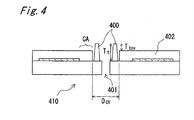
- Fig. 4 shows an example of an optical data recording medium 410 in which the configuration from the spindle hole to the clamping area differs from the configuration shown in Fig. 1 .
- This disc differs from that shown in Fig. 1 in that the transparent protective layer 402 also covers the clamping area CA but is absent around the spindle hole 401.
- the protrusion 400 is located between the spindle hole 401 and the inside diameter of clamping area CA.
- T tcv is 0.1 mm to 0.5 mm.
- the transparent protective layer prefferably not be formed in the clamping area CA.
- the protrusions cannot be disposed to any desired place on the optical disc, and more specifically must be disposed where there will be no contact between the protrusions and the optical head.
- the protrusions are disposed in the area between the spindle hole and clamping area CA.
- the optical head When reading and/or writing data to the signal recording layer the optical head is always on the outside circumference side of the clamping area CA. As a result, there is no contact between the optical head and the protrusions, which are on the inside circumference side of the clamping area CA and separated from the optical head by the clamping area CA.
- FIG. 5 A method of manufacturing these protrusions according to the present invention is shown in Fig. 5 using by way of example an injection molding process.
- a pair of dies 500 is prepared and a stamper 501 is set in one die as shown in Fig. 5A .
- This stamper 501 contains signal 517.
- the side of the dies 500 holding the stamper 501 also has cavities 502. These cavities 502 are formed to the desired shape of the protrusion.
- the mold 500 is then closed as shown in Fig. 5B and molten resin 510 is injected.
- the molten resin 510 thus penetrates the signal 517 pattern and the cavities 502.
- the mold is then cooled and spindle hole 511 is stamped as shown in Fig. 5C to obtain a signal substrate 516 with signal 517 formed in the surface thereof.
- a signal recording layer is then formed over the signal 517 surface, and a transparent protective layer is formed as shown in Fig. 4 .
- a transparent protective layer is formed from above the protrusion 515 to produce an optical data recording medium 110 as shown in Fig. 1 . Because the transparent protective layer also accumulates on the protrusion 515, a protrusion with the same shape is also formed in the transparent protective layer.
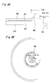
- Fig. 6 shows a method in which parts having the desired shape of the protrusion are fixed to the disc surface with adhesive.
- the desirably shaped protrusions 600 are bonded to the flat surface of the optical data recording medium 601, that is, a disc having no surface protrusions.
- a pressure-sensitive adhesive, UV-cured resin, or thermosetting resin, for example, could be used.
- the material used for the protrusions 600 is preferably lightweight, easy to handle, and low cost, and resin is therefore suitable.
- the material for bonding the protrusions 600 can be precoated to the part of the protrusions 600 that will touch the protrusion-less disc 601.
- the part touching the protrusion-less disc 601 could be heated and melted for bonding.
- the protrusions 600 could even be metal.
- a flat optical data recording medium 601 having no protrusions could be manufactured in one process, parts forming the protrusions can be produced in a separate process to the desired shapes, and protrusions with a particular desired shape could then be bonded to the disc surface. This method offers wide design latitude.
- Fig. 7 shows a method in which drops of liquid resin are deposited and cured on the disc surface.
- liquid resin 700 is dripped from a nozzle 701 to the desired locations on the protrusion-less disc 601.
- the protrusion-less disc 601 can rotated or moved, or the nozzle 701 could be moved, while dripping the resin.
- the liquid resin 700 in this case is preferably a UV-cured resin or thermosetting resin.
- the resin is dripped onto the signal substrate.
- Protrusions can also be formed from a liquid resin using a screen printing process.
- a printing screen is formed with the desired shape of the protrusions, and the liquid resin is screen-printed onto the disc surface. Because the method shown in Fig. 7 does not require preparing and handling discrete protrusion parts, it can form the protrusions more economically than the process shown in Fig. 6 .
- an optical data recording medium has one or more protrusions located on the surface between the inside circumference of the clamping area CA and the outside edge of the spindle hole, assuring that the protrusions will not contact the optical head during recording or playback.
- the proximity of the protrusions to the spindle hole minimizes the effect of any weight imbalance in the protrusion part. A stable, high quality signal can therefore be achieved.
- Fig. 8 shows an optical data recording medium 810 having a protrusion 800 disposed in the area between the clamping area CA and signal area SA.
- Fig. 8A is a section view and Fig. 8B is a plan view from the transparent protective layer 802 side of the disc.
- the inside diameter and outside diameter of the clamping area CA and signal area SA are the same as in the first embodiment.
- the thickness of the transparent protective layer 802 is also the same as in the first embodiment.
- the height T tcv of the protrusion 800 is 0.25 mm.
- the protrusion 800 is formed on the surface of signal substrate 804.
- Fig. 9 is a partial section view when reading and/or writing the optical disc.
- the distance between the optical head and the high density optical disc is generally very small, typically 0.1 to 0.4 mm.
- a working distance WD of 0.4 mm or less is recommended, for example, in ISO M 2002 Technical Digest ThB.1 published by the international Symposium on Optical Memory.
- the optical head can easily strike the transparent protective layer of the disc when the focusing servo is disrupted by such external factors as vibration of the disc surface.
- the high NA used with high density optical discs means that dust on the surface of the transparent protective layer can easily disrupt the focusing servo.
- the optical head can easily collide with the protrusion on the disc surface.
- a shield for protecting the lens is required on the surface of the optical head. The thickness of this shield (approximately 0.1 mm) further decreases the working distance to 0.3 mm or less. If the working distance of the optical head increases, the outside diameter of the lens also increases.
- the outside diameter f of a lens with a 0.4 mm working distance is 6 mm to 8 mm (including the lens holder).
- the lens holder 900 When reading and/or writing the signal area with inside diameter D SAI as shown in Fig. 9 , the lens holder 900 intrudes on the area between clamping area CA and signal area SA by an amount equal to the radius R part of the lens holder 900.
- the actual working distance WD of the lens is a narrow 0.2 mm to 0.3 mm. That is, with an optical data recording medium as shown in Fig. 8 , the optimal height T tcv of the protrusion will differ according to the location of the protrusion.
- the height T tcv must therefore be lowered.
- the actual working distance WD of the lens is 0.2 mm, there is 0.5 mm of space between the lens holder 900 and protrusion 800 because the radius R of the lens holder is approximately 3 mm. Radius R is approximately 4 mm if the working distance WD is 0.3 mm, but because height T tcv is 0.25 mm, the protrusion 800 will not collide with the lens holder 900.
- the protrusion can be located in the area between the clamping area CA and signal area SA as described in this second embodiment of the invention whether the transparent protective layer is not formed in the clamping area CA as shown in Fig. 8 , or whether the area of the transparent protective layer is disposed to an area as shown in Fig. 1 or Fig. 4 .
- the protrusion in this second embodiment can also be manufactured using the same materials and methods described in the first embodiment. Note that depending upon the inside diameter of the stamper, it may be necessary to provide a cavity in the stamper with the injection molding method shown in Fig. 5 . For example, if the inside diameter of the stamper is less than 33 mm, the stamper thickness could be increased and a cavity of desirable depth and configuration formed in the stamper by etching or machining. As shown in Fig. 10 , a protrusion 1001 can be formed on the signal substrate and the transparent protective layer 1010 formed thereon to form the surface protrusion 1000. The protrusion can also be formed on an optical data recording medium as shown in Fig. 8 by a molding process such as shown in Fig. 5 .
- the shape and configuration of the protrusion can be the same as described in the first embodiment above.
- the protrusion is in an area between the clamping area CA and signal area SA as described in this second embodiment of the invention, and particularly when the protrusion is within 2 mm on the outside circumference side of the clamping area CA, collision of the optical head with the protrusion can be prevented during both recording and playback, and surface scratches can be prevented even when the optical data recording medium is placed on a flat surface with the transparent protective layer of the disc facing the flat surface because the protrusion assures that the surface of the disc does not contact the surface on which it is placed.
- FIG. 11 An optical data recording medium in which the protrusion is located in the clamping area CA is shown in Fig. 11 as a third embodiment of the present invention.
- Fig. 11A is a section view of the disc.
- the inside diameter D ti and outside diameter D to of the protrusion 1100 are defined by the following relation.
- This configuration also prevents scratching when the optical data recording medium 1110 is placed on a flat surface with the transparent protective layer 1102 facing the flat surface because the protrusion assures a sufficient gap between the transparent protective layer 1102 and said flat surface.
- inside diameter D CAI inside diameter
- outside diameter D CAO outside diameter
- the width of the protrusion 1100 and the height of the protrusion from the surface of the transparent protective layer 1102 are also the same as in the first embodiment, that is, in the ranges 0.2 mm to 1 mm, and 0.1 mm to 0.5 mm, respectively.
- Fig. 11B and Fig. 11C show two different ways of clamping the optical data recording medium 1110 on both sides of the protrusion 1100.
- the clamp 1120 applies pressure to the disc in the clamping area on both sides of the protrusion 1100.
- the disc can be held with sufficient force in this case despite the protrusion 1100 because the clamping member has a channel providing clearance for the protrusion 1100.
- the clamp 1130 applies pressure to the disc in the clamping area on both sides of the protrusion 1100, and also applies pressure to the protrusion 1100.
- This method provides even more positive clamping of the disc because pressure is applied to a larger area of the disc than with the method shown in Fig. 11B .
- the optical data recording medium can be held stable and rotated with sufficient pressure during both recording and playback to assure good signal quality and reliable recording and playback performance.
- the disc is clamped on both sides of the protrusion 1100 in this embodiment, but it could be held only in the area between inside diameter D CAI and the inside circumference edge of the protrusion 1100, or the area between outside diameter D CAO and the outside circumference edge of the protrusion 1100.
- this third embodiment has been described with reference to the configuration shown in Fig. 11 , it could be configured as shown in Fig. 4 and Fig. 8 . That is, this protrusion could be used on a disc in which the transparent protective layer is not formed in the clamping area CA, or on a disc in which the transparent protective layer is not in the clamping area CA and there is a step between the surface elevations of the signal substrate and the transparent protective layer.
- the protrusion 1100 of this third embodiment can also be formed using the same materials and methods described in the first and second embodiments above.
- the shape and configuration of the protrusion could also be as described in the first embodiment.
- Clamping an optical data recording medium according to the present invention shall not be limited to holding the disc with chucking jaws in the clamping area CA on only one side of the disc as shown in Fig. 12A to Fig. 12C and Fig. 15 . More specifically, the optical data recording medium could be clamped from both sides of the disc.
- Fig. 16 a section view of the optical data recording medium 1600 being clamped in the clamping area CA from above and below the disc by means of a top clamp 1605 and a bottom clamp 1606.
- the protrusion 1601 is disposed in the camping area CA, and the area on both sides of the protrusion 1601 is supported by bottom clamp 1606 on the laser-incidence side of the disc.
- the material used to manufacture the signal substrate is not particularly discussed in the above-described embodiments, but is preferably a plastic such as polycarbonate, norbornene resin, or polyolefin resin.
- the transparent protective layer can also be formed by applying a sheet film thinner than the desired thickness with adhesive, or applying a coat of liquid resin.
- the adhesive could be a UV-cure resin, thermosetting resin, or pressure sensitive adhesive, for example.
- the resin could be a UV-cure resin or thermosetting resin, for example.
Landscapes
- Engineering & Computer Science (AREA)
- Mechanical Engineering (AREA)
- Manufacturing & Machinery (AREA)
- Physics & Mathematics (AREA)
- Optics & Photonics (AREA)
- Optical Record Carriers And Manufacture Thereof (AREA)
- Manufacturing Optical Record Carriers (AREA)
- Holo Graphy (AREA)
- Optical Recording Or Reproduction (AREA)
- Holding Or Fastening Of Disk On Rotational Shaft (AREA)
Applications Claiming Priority (5)
| Application Number | Priority Date | Filing Date | Title |
|---|---|---|---|
| JP2002260192 | 2002-09-05 | ||
| JP2002320017 | 2002-11-01 | ||
| JP2003068752 | 2003-03-13 | ||
| EP08169836A EP2043098B1 (en) | 2002-09-05 | 2003-09-04 | Optical data recording medium |
| EP03020041A EP1396855B1 (en) | 2002-09-05 | 2003-09-04 | Optical data recording medium and manufacturing method for the same; and a method for clamping the optical data recording medium |
Related Parent Applications (2)
| Application Number | Title | Priority Date | Filing Date |
|---|---|---|---|
| EP03020041.4 Division | 2003-09-04 | ||
| EP08169836.7 Division | 2008-11-25 |
Publications (1)
| Publication Number | Publication Date |
|---|---|
| EP2180474A1 true EP2180474A1 (en) | 2010-04-28 |
Family
ID=31721296
Family Applications (7)
| Application Number | Title | Priority Date | Filing Date |
|---|---|---|---|
| EP03020041A Expired - Lifetime EP1396855B1 (en) | 2002-09-05 | 2003-09-04 | Optical data recording medium and manufacturing method for the same; and a method for clamping the optical data recording medium |
| EP10151149A Withdrawn EP2180475A1 (en) | 2002-09-05 | 2003-09-04 | Optical data recording medium and recording and playback method |
| EP10151150A Withdrawn EP2180476A1 (en) | 2002-09-05 | 2003-09-04 | Optical data recording medium and recording and playback method |
| EP10151148A Withdrawn EP2180474A1 (en) | 2002-09-05 | 2003-09-04 | Optical data recording medium and manufacturing method for the same, and a method for clamping the optical data recording medium |
| EP10176248A Withdrawn EP2278586A1 (en) | 2002-09-05 | 2003-09-04 | Optical data recording medium and manufacturing method for the same |
| EP10151153A Expired - Lifetime EP2180472B1 (en) | 2002-09-05 | 2003-09-04 | Optical data recording medium and recording and playback method |
| EP08169836A Expired - Lifetime EP2043098B1 (en) | 2002-09-05 | 2003-09-04 | Optical data recording medium |
Family Applications Before (3)
| Application Number | Title | Priority Date | Filing Date |
|---|---|---|---|
| EP03020041A Expired - Lifetime EP1396855B1 (en) | 2002-09-05 | 2003-09-04 | Optical data recording medium and manufacturing method for the same; and a method for clamping the optical data recording medium |
| EP10151149A Withdrawn EP2180475A1 (en) | 2002-09-05 | 2003-09-04 | Optical data recording medium and recording and playback method |
| EP10151150A Withdrawn EP2180476A1 (en) | 2002-09-05 | 2003-09-04 | Optical data recording medium and recording and playback method |
Family Applications After (3)
| Application Number | Title | Priority Date | Filing Date |
|---|---|---|---|
| EP10176248A Withdrawn EP2278586A1 (en) | 2002-09-05 | 2003-09-04 | Optical data recording medium and manufacturing method for the same |
| EP10151153A Expired - Lifetime EP2180472B1 (en) | 2002-09-05 | 2003-09-04 | Optical data recording medium and recording and playback method |
| EP08169836A Expired - Lifetime EP2043098B1 (en) | 2002-09-05 | 2003-09-04 | Optical data recording medium |
Country Status (13)
| Country | Link |
|---|---|
| US (9) | US7065776B2 (zh) |
| EP (7) | EP1396855B1 (zh) |
| JP (6) | JP3961466B2 (zh) |
| KR (3) | KR20040022200A (zh) |
| CN (10) | CN101373615A (zh) |
| AT (3) | ATE479184T1 (zh) |
| CY (1) | CY1112659T1 (zh) |
| DE (2) | DE60325816D1 (zh) |
| DK (1) | DK2180472T3 (zh) |
| ES (3) | ES2348824T3 (zh) |
| MX (1) | MXPA03007951A (zh) |
| PT (3) | PT2043098E (zh) |
| SI (3) | SI2180472T1 (zh) |
Families Citing this family (30)
| Publication number | Priority date | Publication date | Assignee | Title |
|---|---|---|---|---|
| US7297122B2 (en) * | 2002-04-19 | 2007-11-20 | Pelikan Technologies, Inc. | Method and apparatus for penetrating tissue |
| JP3961466B2 (ja) * | 2002-09-05 | 2007-08-22 | 松下電器産業株式会社 | 光情報記録媒体及びその製造方法、並びに光情報記録媒体の保持方法 |
| AU2006220971A1 (en) | 2005-03-03 | 2006-09-14 | Enxnet, Inc. | Optical disc having a reduced planar thickness |
| FR2887678B1 (fr) * | 2005-06-28 | 2007-09-28 | Digital Valley | Disque numerique universel |
| WO2007027120A1 (fr) * | 2005-08-30 | 2007-03-08 | Andrei Vladimirovich Tropillo | Support de donnees en forme de disque |
| US7716695B2 (en) | 2005-10-07 | 2010-05-11 | Enxnet, Inc. | Thin optical disc having remote reading capability |
| EP1932151A4 (en) | 2005-10-07 | 2009-01-21 | Enxnet Inc | THIN OPTICAL CARRIER WITH REMOTE POSSIBILITY |
| CN101449326B (zh) * | 2006-05-18 | 2011-08-03 | 松下电器产业株式会社 | 多层光记录介质的制造方法 |
| JP2008004252A (ja) | 2006-05-26 | 2008-01-10 | Tdk Corp | 情報媒体用基板および情報媒体 |
| US7785689B2 (en) * | 2006-08-21 | 2010-08-31 | Imation Corp. | Raw material conserving optical data storage media |
| EP2284834A1 (en) * | 2006-11-15 | 2011-02-16 | EcoDisc Technology AG | Eco disc |
| US20080115158A1 (en) * | 2006-11-15 | 2008-05-15 | Al Fetouhi | Optical Medium Manufacture |
| EP1923873A1 (en) | 2006-11-15 | 2008-05-21 | ODS Technology GmbH | EcoDisc |
| DE06023768T1 (de) * | 2006-11-15 | 2008-10-23 | Ods Technology Gmbh | EcoDisc |
| EP2117003A3 (en) * | 2006-11-20 | 2010-01-13 | EcoDisc Technology AG | Smart video card |
| US20100220582A1 (en) * | 2007-03-06 | 2010-09-02 | Andrei Vladimirovich Tropillo | Disc-shaped information-carrying medium |
| JPWO2008111387A1 (ja) * | 2007-03-15 | 2010-06-24 | コニカミノルタオプト株式会社 | 記録媒体用基板、及び記録媒体用基板の製造方法 |
| CN101435992B (zh) * | 2007-11-15 | 2012-05-30 | 北京京东方光电科技有限公司 | 形成光刻胶图案的方法 |
| US8137782B2 (en) * | 2008-10-27 | 2012-03-20 | Imation Corp. | Optical media manufactured with low-grade materials |
| US7995452B2 (en) * | 2008-11-10 | 2011-08-09 | Imation Corp. | Thin optical data storage media with hard coat |
| US8561093B2 (en) * | 2009-02-26 | 2013-10-15 | Imation Corp. | Stacking techniques for thin optical data storage media |
| KR101040655B1 (ko) * | 2009-05-12 | 2011-06-13 | 김봉석 | 와이어 신선장치 |
| EP2341503A1 (de) * | 2009-12-21 | 2011-07-06 | Thomson Licensing | Plattenförmiges Speichermedium und Klemmhalter für das Speichermedium |
| JP4904421B2 (ja) * | 2010-08-16 | 2012-03-28 | シバテック株式会社 | ディスク型記録媒体 |
| NO335251B1 (no) | 2011-03-29 | 2014-10-27 | Trosterud Mekaniske Verksted As | Fremgangsmåte og anordning for distribusjon av tørrissnø |
| JP5971564B2 (ja) * | 2011-05-10 | 2016-08-17 | パナソニックIpマネジメント株式会社 | 情報記録媒体および情報記録媒体を保持する保持装置 |
| AU2014232390A1 (en) | 2013-03-15 | 2015-10-08 | Kenneth POST | Cleaning apparatus |
| WO2016056238A1 (ja) * | 2014-10-09 | 2016-04-14 | パナソニックIpマネジメント株式会社 | 光ディスク、マガジン装置、および光ディスクの製造方法 |
| CN107237217B (zh) * | 2016-03-28 | 2019-11-26 | 诚宗环保科技(上海)有限公司 | 模塑产品自动成型机及制造方法及成品 |
| US11998153B2 (en) | 2019-12-26 | 2024-06-04 | Kenneth Post | Handheld cleaning apparatus |
Citations (1)
| Publication number | Priority date | Publication date | Assignee | Title |
|---|---|---|---|---|
| US20010053121A1 (en) | 2000-06-09 | 2001-12-20 | Tdk Corporation | Optical information medium and making method |
Family Cites Families (53)
| Publication number | Priority date | Publication date | Assignee | Title |
|---|---|---|---|---|
| DE2939865C2 (de) * | 1979-10-02 | 1982-09-02 | Licentia Patent-Verwaltungs-Gmbh, 6000 Frankfurt | Verfahren und Vorrichtung zur Zentrierung und Ausrichtung eines plattenförmigen Aufzeichnungsträgers |
| DE3322131A1 (de) * | 1983-06-20 | 1984-12-20 | Polygram Gmbh, 2000 Hamburg | Plattenfoermiger, optisch auslesbarer informationstraeger mit schutzrand |
| JP2542647B2 (ja) * | 1987-11-23 | 1996-10-09 | 太陽誘電株式会社 | 光情報記録媒体 |
| JPH02252151A (ja) * | 1989-03-24 | 1990-10-09 | Kyocera Corp | 光磁気ディスク |
| JPH02260144A (ja) * | 1989-03-30 | 1990-10-22 | Fuji Photo Film Co Ltd | 情報記録媒体およびその記録または再生方法 |
| US5080736A (en) * | 1989-05-26 | 1992-01-14 | Matsui Manufacturing Co., Ltd. | System for mounting a hub to an optical disk and a method therefor |
| JP2507824B2 (ja) * | 1990-06-13 | 1996-06-19 | シャープ株式会社 | 光磁気ディスク及びその製造方法 |
| JP2622017B2 (ja) * | 1990-07-20 | 1997-06-18 | シャープ株式会社 | 光磁気ディスクの製造方法 |
| CA2044427C (en) * | 1990-06-13 | 1997-02-11 | Junichiro Nakayama | Magneto-optical disk and manufacturing methods thereof |
| JP2569627Y2 (ja) * | 1991-12-31 | 1998-04-28 | 太陽誘電株式会社 | 光ディスク用基板 |
| JPH06333316A (ja) * | 1993-05-20 | 1994-12-02 | Nakamichi Corp | ディスク再生装置 |
| JPH06333315A (ja) * | 1993-05-20 | 1994-12-02 | Nakamichi Corp | ディスク再生装置 |
| US5544148A (en) * | 1993-05-20 | 1996-08-06 | Nakamichi Corporation | Compact configuration disk player |
| JPH09219038A (ja) | 1996-02-13 | 1997-08-19 | Pioneer Electron Corp | 光ディスク |
| JPH1040578A (ja) * | 1996-07-23 | 1998-02-13 | Mitsubishi Chem Corp | ディスク用基板 |
| JPH1058497A (ja) * | 1996-08-19 | 1998-03-03 | Sony Disc Technol:Kk | ディスク基板成形用金型及び成形装置 |
| JPH10106044A (ja) * | 1996-09-20 | 1998-04-24 | Sony Disc Technol:Kk | 光ディスク |
| US5895697A (en) * | 1996-11-16 | 1999-04-20 | Taiyo Yuden Co., Ltd. | Optical information medium |
| JP3594002B2 (ja) | 1998-01-21 | 2004-11-24 | ソニー株式会社 | 光ディスク |
| US6077583A (en) * | 1998-03-03 | 2000-06-20 | Park; Arnold | Digital information guard |
| JP4092767B2 (ja) | 1998-04-10 | 2008-05-28 | ソニー株式会社 | 記録媒体及び再生装置 |
| US6307830B1 (en) * | 1998-06-02 | 2001-10-23 | Bradley Shultz | Protected recording medium |
| US6440516B1 (en) * | 1999-01-20 | 2002-08-27 | Sony Corporation | Optical disc |
| JP2000331377A (ja) * | 1999-05-21 | 2000-11-30 | Victor Co Of Japan Ltd | 光ディスク |
| JP2001067730A (ja) | 1999-08-31 | 2001-03-16 | Sony Miyuujitsuku Entertainment:Kk | 光ディスク及びその製造方法 |
| JP2001093193A (ja) | 1999-09-21 | 2001-04-06 | Sony Disc Technology Inc | 光ディスク |
| EP1264851B1 (en) * | 2000-02-07 | 2006-07-19 | Nagoya Oilchemical Co., Ltd. | Resin composition, molding material, and molded object |
| JP3908478B2 (ja) | 2000-04-25 | 2007-04-25 | 松下電器産業株式会社 | 凸部を有する光ディスク |
| EP1152407A3 (en) * | 2000-04-25 | 2006-10-25 | Matsushita Electric Industrial Co., Ltd. | Optical disk, method for producing the same, and apparatus for producing the same |
| JP4043175B2 (ja) * | 2000-06-09 | 2008-02-06 | Tdk株式会社 | 光情報媒体およびその製造方法 |
| ATE459959T1 (de) * | 2000-11-20 | 2010-03-15 | Sony Corp | Optisches aufzeichnungsmedium und optisches plattengeraet |
| JP2002170279A (ja) * | 2000-11-30 | 2002-06-14 | Sony Corp | 光学記録媒体およびその製造方法、ならびに射出成形装置 |
| KR100419211B1 (ko) * | 2000-12-20 | 2004-02-19 | 삼성전자주식회사 | 디스크형 기록매체 |
| JP2002237095A (ja) * | 2001-02-07 | 2002-08-23 | Ricoh Co Ltd | 光情報記録媒体 |
| US6680898B2 (en) * | 2001-02-21 | 2004-01-20 | Todd J. Kuchman | Optical disc and method of protecting same |
| US6842409B2 (en) * | 2001-02-21 | 2005-01-11 | Scratch-Less Disc Industries, Llc | Optical disc and method of protecting same |
| US6865745B2 (en) * | 2001-08-10 | 2005-03-08 | Wea Manufacturing, Inc. | Methods and apparatus for reducing the shrinkage of an optical disc's clamp area and the resulting optical disc |
| TWI222908B (en) * | 2001-08-30 | 2004-11-01 | Toshiba Machine Co Ltd | Vertical lathe, tool head for vertical lathe, rotary table apparatus for machine tool |
| US6667953B2 (en) * | 2001-12-21 | 2003-12-23 | Seth Matson | Optical disk protector and method of use |
| US6901600B2 (en) * | 2002-01-03 | 2005-05-31 | Julian Liu | Protective cover for a data storage disc and method of use |
| JP2003242680A (ja) * | 2002-02-13 | 2003-08-29 | Sony Corp | ディスク状光記録媒体 |
| US6768867B2 (en) * | 2002-05-17 | 2004-07-27 | Olympus Corporation | Auto focusing system |
| MXPA03005877A (es) * | 2002-07-04 | 2006-04-24 | Matsushita Electric Ind Co Ltd | Medio de grabacion de datos opticos y metodo de fabricacion del mismo. |
| KR20040004742A (ko) * | 2002-07-05 | 2004-01-14 | 김경환 | 대향타겟식 스퍼터링법을 이용한 고배향성 박막 제작법 |
| JP4167859B2 (ja) | 2002-07-05 | 2008-10-22 | Tdk株式会社 | 光記録媒体用中間体および光記録媒体の製造方法 |
| JP3961466B2 (ja) * | 2002-09-05 | 2007-08-22 | 松下電器産業株式会社 | 光情報記録媒体及びその製造方法、並びに光情報記録媒体の保持方法 |
| KR100499479B1 (ko) * | 2002-09-10 | 2005-07-05 | 엘지전자 주식회사 | 고밀도 광디스크 구조 |
| KR20040047424A (ko) | 2002-11-30 | 2004-06-05 | 삼성전자주식회사 | 광 드라이브용 디스크 |
| KR20040091938A (ko) * | 2003-04-23 | 2004-11-03 | 삼성전자주식회사 | 광디스크 |
| US20050160442A1 (en) * | 2004-01-16 | 2005-07-21 | Kaplowitz Gary H. | Optical data storage device protector |
| US20090028039A1 (en) * | 2004-09-08 | 2009-01-29 | Kazuya Hisada | Method for producing optical information recording medium and optical information recording medium |
| US7716695B2 (en) | 2005-10-07 | 2010-05-11 | Enxnet, Inc. | Thin optical disc having remote reading capability |
| US20080115158A1 (en) * | 2006-11-15 | 2008-05-15 | Al Fetouhi | Optical Medium Manufacture |
-
2003
- 2003-09-02 JP JP2003310352A patent/JP3961466B2/ja not_active Expired - Lifetime
- 2003-09-04 ES ES08169836T patent/ES2348824T3/es not_active Expired - Lifetime
- 2003-09-04 EP EP03020041A patent/EP1396855B1/en not_active Expired - Lifetime
- 2003-09-04 ES ES10151153T patent/ES2376041T3/es not_active Expired - Lifetime
- 2003-09-04 EP EP10151149A patent/EP2180475A1/en not_active Withdrawn
- 2003-09-04 DE DE60325816T patent/DE60325816D1/de not_active Expired - Lifetime
- 2003-09-04 PT PT08169836T patent/PT2043098E/pt unknown
- 2003-09-04 SI SI200332089T patent/SI2180472T1/sl unknown
- 2003-09-04 CN CNA2008101657496A patent/CN101373615A/zh active Pending
- 2003-09-04 CN CNA2008101657462A patent/CN101373612A/zh active Pending
- 2003-09-04 CN CNA2008101657477A patent/CN101373613A/zh active Pending
- 2003-09-04 EP EP10151150A patent/EP2180476A1/en not_active Withdrawn
- 2003-09-04 EP EP10151148A patent/EP2180474A1/en not_active Withdrawn
- 2003-09-04 CN CNA2008101657509A patent/CN101373616A/zh active Pending
- 2003-09-04 CN CN2008101657513A patent/CN101373617B/zh not_active Expired - Fee Related
- 2003-09-04 SI SI200331864T patent/SI2043098T1/sl unknown
- 2003-09-04 CN CN2008101657528A patent/CN101373618B/zh not_active Expired - Fee Related
- 2003-09-04 AT AT08169836T patent/ATE479184T1/de active
- 2003-09-04 CN CNB031580521A patent/CN100433152C/zh not_active Expired - Fee Related
- 2003-09-04 EP EP10176248A patent/EP2278586A1/en not_active Withdrawn
- 2003-09-04 DE DE60333964T patent/DE60333964D1/de not_active Expired - Lifetime
- 2003-09-04 AT AT10151153T patent/ATE534121T1/de active
- 2003-09-04 AT AT03020041T patent/ATE421142T1/de not_active IP Right Cessation
- 2003-09-04 PT PT10151153T patent/PT2180472E/pt unknown
- 2003-09-04 ES ES03020041T patent/ES2319514T3/es not_active Expired - Lifetime
- 2003-09-04 CN CNA2008101657443A patent/CN101373610A/zh active Pending
- 2003-09-04 EP EP10151153A patent/EP2180472B1/en not_active Expired - Lifetime
- 2003-09-04 EP EP08169836A patent/EP2043098B1/en not_active Expired - Lifetime
- 2003-09-04 CN CNA2008101657481A patent/CN101373614A/zh active Pending
- 2003-09-04 PT PT03020041T patent/PT1396855E/pt unknown
- 2003-09-04 CN CNA2008101657458A patent/CN101373611A/zh active Pending
- 2003-09-04 DK DK10151153.3T patent/DK2180472T3/da active
- 2003-09-04 SI SI200331495T patent/SI1396855T1/sl unknown
- 2003-09-04 MX MXPA03007951A patent/MXPA03007951A/es active IP Right Grant
- 2003-09-05 KR KR1020030062114A patent/KR20040022200A/ko not_active Application Discontinuation
- 2003-09-05 US US10/655,135 patent/US7065776B2/en not_active Expired - Lifetime
-
2006
- 2006-03-02 US US11/365,819 patent/US7290272B2/en not_active Expired - Lifetime
- 2006-07-28 JP JP2006206207A patent/JP3961549B2/ja not_active Expired - Fee Related
-
2007
- 2007-02-23 JP JP2007043959A patent/JP4068655B2/ja not_active Expired - Lifetime
- 2007-06-07 JP JP2007151334A patent/JP4105217B2/ja not_active Expired - Lifetime
- 2007-09-12 US US11/898,461 patent/US7389520B2/en not_active Expired - Lifetime
- 2007-09-12 US US11/898,462 patent/US7409699B2/en not_active Expired - Fee Related
- 2007-09-12 US US11/898,463 patent/US7401346B2/en not_active Expired - Fee Related
- 2007-09-25 US US11/902,733 patent/US7401347B2/en not_active Expired - Fee Related
- 2007-10-22 KR KR1020070106120A patent/KR20070110469A/ko not_active Application Discontinuation
- 2007-11-05 KR KR1020070111881A patent/KR20070116764A/ko not_active Application Discontinuation
-
2008
- 2008-01-29 JP JP2008017124A patent/JP4638918B2/ja not_active Expired - Lifetime
- 2008-02-12 US US12/068,871 patent/US7761888B2/en not_active Expired - Fee Related
- 2008-02-12 US US12/068,869 patent/US20080148305A1/en not_active Abandoned
-
2010
- 2010-06-08 US US12/795,859 patent/US20100242059A1/en not_active Abandoned
- 2010-09-01 JP JP2010195573A patent/JP5065461B2/ja not_active Expired - Fee Related
-
2012
- 2012-02-06 CY CY20121100121T patent/CY1112659T1/el unknown
Patent Citations (1)
| Publication number | Priority date | Publication date | Assignee | Title |
|---|---|---|---|---|
| US20010053121A1 (en) | 2000-06-09 | 2001-12-20 | Tdk Corporation | Optical information medium and making method |
Also Published As
Similar Documents
| Publication | Publication Date | Title |
|---|---|---|
| US7290272B2 (en) | Optical data recording disc with protrusion between clamping area and center hole | |
| KR20090107993A (ko) | 광정보 기록매체, 광정보 재생 장치 및 광정보 기록 장치 |
Legal Events
| Date | Code | Title | Description |
|---|---|---|---|
| PUAI | Public reference made under article 153(3) epc to a published international application that has entered the european phase |
Free format text: ORIGINAL CODE: 0009012 |
|
| AC | Divisional application: reference to earlier application |
Ref document number: 1396855 Country of ref document: EP Kind code of ref document: P Ref document number: 2043098 Country of ref document: EP Kind code of ref document: P |
|
| AK | Designated contracting states |
Kind code of ref document: A1 Designated state(s): AT BE BG CH CY CZ DE DK EE ES FI FR GB GR HU IE IT LI LU MC NL PT RO SE SI SK TR |
|
| AX | Request for extension of the european patent |
Extension state: AL LT LV MK |
|
| 17P | Request for examination filed |
Effective date: 20101028 |
|
| RIC1 | Information provided on ipc code assigned before grant |
Ipc: B29D 17/00 20060101ALI20110113BHEP Ipc: B29C 45/26 20060101ALI20110113BHEP Ipc: G11B 7/24 20060101ALI20110113BHEP Ipc: G11B 17/028 20060101AFI20110113BHEP |
|
| GRAP | Despatch of communication of intention to grant a patent |
Free format text: ORIGINAL CODE: EPIDOSNIGR1 |
|
| STAA | Information on the status of an ep patent application or granted ep patent |
Free format text: STATUS: THE APPLICATION IS DEEMED TO BE WITHDRAWN |
|
| 18D | Application deemed to be withdrawn |
Effective date: 20111101 |