EP2119641A1 - Method and device for a waste collecting vehicle - Google Patents
Method and device for a waste collecting vehicle Download PDFInfo
- Publication number
- EP2119641A1 EP2119641A1 EP09157921A EP09157921A EP2119641A1 EP 2119641 A1 EP2119641 A1 EP 2119641A1 EP 09157921 A EP09157921 A EP 09157921A EP 09157921 A EP09157921 A EP 09157921A EP 2119641 A1 EP2119641 A1 EP 2119641A1
- Authority
- EP
- European Patent Office
- Prior art keywords
- turntable
- waste
- cradle
- lift
- emptying
- Prior art date
- Legal status (The legal status is an assumption and is not a legal conclusion. Google has not performed a legal analysis and makes no representation as to the accuracy of the status listed.)
- Granted
Links
- 239000002699 waste material Substances 0.000 title claims abstract description 31
- 238000000034 method Methods 0.000 title claims abstract description 8
- 230000000977 initiatory effect Effects 0.000 claims abstract description 4
- 238000005192 partition Methods 0.000 claims abstract description 3
- 230000002265 prevention Effects 0.000 claims abstract description 3
- 230000005540 biological transmission Effects 0.000 claims description 7
- 230000002452 interceptive effect Effects 0.000 claims description 2
- 239000004744 fabric Substances 0.000 description 4
- 239000000463 material Substances 0.000 description 3
- 229910052751 metal Inorganic materials 0.000 description 2
- 239000002184 metal Substances 0.000 description 2
- 239000004411 aluminium Substances 0.000 description 1
- 229910052782 aluminium Inorganic materials 0.000 description 1
- XAGFODPZIPBFFR-UHFFFAOYSA-N aluminium Chemical compound [Al] XAGFODPZIPBFFR-UHFFFAOYSA-N 0.000 description 1
- 230000004888 barrier function Effects 0.000 description 1
- 239000000428 dust Substances 0.000 description 1
- 230000000694 effects Effects 0.000 description 1
- 230000005484 gravity Effects 0.000 description 1
- 230000003993 interaction Effects 0.000 description 1
- 238000004806 packaging method and process Methods 0.000 description 1
- 230000001681 protective effect Effects 0.000 description 1
- 238000011084 recovery Methods 0.000 description 1
Images


Classifications
-
- B—PERFORMING OPERATIONS; TRANSPORTING
- B65—CONVEYING; PACKING; STORING; HANDLING THIN OR FILAMENTARY MATERIAL
- B65F—GATHERING OR REMOVAL OF DOMESTIC OR LIKE REFUSE
- B65F3/00—Vehicles particularly adapted for collecting refuse
- B65F3/02—Vehicles particularly adapted for collecting refuse with means for discharging refuse receptacles thereinto
- B65F3/08—Platform elevators or hoists with guides or runways for raising or tipping receptacles
-
- B—PERFORMING OPERATIONS; TRANSPORTING
- B65—CONVEYING; PACKING; STORING; HANDLING THIN OR FILAMENTARY MATERIAL
- B65F—GATHERING OR REMOVAL OF DOMESTIC OR LIKE REFUSE
- B65F3/00—Vehicles particularly adapted for collecting refuse
- B65F3/001—Vehicles particularly adapted for collecting refuse for segregated refuse collecting, e.g. vehicles with several compartments
Definitions
- the present invention relates to a procedure and a device at a waste-transportation vehicle for, by means of at least two lift cradles having variable initiation height and being fitted thereto in a boot or trunk, allowing, without mixing together, the lifting and emptying of different waste fractions into one dust compartment for each fraction from different standardized dustbins in the same vehicle having one lift cradle for each waste fraction.
- the waste is handled in such a way that it is loaded into a load container belonging to the vehicle from dustbins that are attached to a motor-driven guide mechanism arranged at the rear part of the vehicle and from where it, using means belonging to the vehicle, is brought into the load space, where it is compressed.
- a load container belonging to the vehicle from dustbins that are attached to a motor-driven guide mechanism arranged at the rear part of the vehicle and from where it, using means belonging to the vehicle, is brought into the load space, where it is compressed.
- recyclable material of different types e.g., returnable packaging's such as aluminium cans or PET bottles, respectively.
- the waste is scanned, e.g., the PET fraction is scanned using a metal detector in order to find out whether the load is "clean" from metal contents or not. If this is not the case, the lot has to be discarded as a consequence of it being too resource-demanding to manually search through the lot.
- the respective lift cradle is mounted for the prevention of spillage beside the intended waste container on a turntable that, if the size of the bin is such that some part of the opening thereof during the course of emptying in connection with turning for emptying risks ending up above a partition or external wall of a waste container, the bin is lowered by means of the turntable by a motion co-ordinated with the motion of the lift cradle so much that this is prevented.
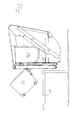
- the instant invention generally relates to a device for a lift cradle for a waste-transportation vehicle, more specifically a lift cradle 1, 2 intended to be arranged on the rear of such a vehicle.
- FIG. 1 which in a perspective view shows a rear part of the lift cradle(s) 1, 2 of a waste-transportation vehicle, as well as a waste container 3 and 4, respectively, associated to each such cradle, as well as also a dustbin 5 that is rolled out into a position for taxing in, lifting and emptying.
- the lift cradle 1 of one 3 of the containers is in a lower position for the lifting and emptying of a dustbin from ground level, while the lift cradle 2 of the other one 4 of the containers is in a position for the lifting and emptying of a dustbin from a level that corresponds to a loading dock/loading ramp or the like.
- the respective lift cradle 1, 2 is driven via a chain transmission 6 of a hydraulic motor 7 in order to move up or down. From this figure, it is also seen that each one of the two lift cradles, at the respective bottom parts thereof, embodies an extensible rubber cloth 8, which serves as spillage protection but also constitutes stipulated safety barrier to be drawn out automatically in connection with the motion of the lift cradle.
- the rubber cloth is arranged in the form of a roller-blind-like arrangement in such a way that the extension thereof from a storage roller takes place simultaneously with the cradle being pushed upward and the rubber cloth automatically returning at the same time as the cradle is brought back to the lower position thereof.
- Fig. 2 shows the lift cradles 1, 2 as seen straight from behind, and similarly to Fig. 1 , the right cradle 2 herein is here shown elevated into a state for emptying from a loading dock or the like. Because of that, the rubber cloth 8 is, as has been described, also drawn up. The left lift cradle is in the lower position thereof, and thus in a state for emptying of a dustbin from ground level. In this figure, the hydraulic motors 7 of the respective lift cradles 1, 2 are seen more clearly. In this view, the chain transmissions 6 are concealed behind protective plates 9.
- Fig. 3 shows a side part 10 of a bin lift that stands for hoisting of the respective cradles 1, 2 from the level where the dustbins are collected to the level on which they are emptied.
- the cradles 1, 2 are intended for catching hold of and lifting as well as swinging a dustbin 5 (not shown in this figure) before the same is emptied at the upper part of the respective containers 3, 4.
- the cradles 1, 2 is moved by means of the motor 7 (not shown in this figure) on the output shaft of which there are gears (not shown) that are rolled against movable chains that are fixed to the cradles (not shown) and contained in guides 8.
- One end 12 of the respective lift cradle 1, 2 has a curvature that comprises deep "notches” 13.
- said "notches” 13 are intended to catch hold of pins 17 on a so-called turntable 14, which, under the impact of the motion of the cradle, pretty much as the engagement between a rack and a gear with a large pitch for both, swing around a dustbin 5 that is fixed to the cradle 1, 2 into a position for emptying.
- the turntable 14 is, under the impact of a hydraulic cylinder that acts between itself and a fixed part of either of the containers 3, 4, movable upward/downward in a guide 16.
- a motion indicator (not shown), which is incorporated in the hydraulic control of the turntable, senses when the two notches 13 of a cradle 1, 2 have arrived in such a position that both of them are in engagement with the pins 17 of the turntable 14, wherein the turntable 14 and the chain transmission 6, by means of a functionality that is incorporated in a control unit (not shown) for the move of the cradle 14, both are actuated to execute a co-ordinated motion of the cradle 1, 2 as well as the turntable 14, so that the dustbin will move in a way that means that nothing of the material contained therein falls outside the respective container during a course of emptying.
- FIG. 4 it is seen how the rear part of a waste-transportation vehicle, more precisely containers 3, 4 and lift cradles 1, 2 have been reversed to a loading ramp 18.
- all details described above take part and are present in one or other activity phase.
- the lift cradle is, in a manual or automatic way, elevated into a position in such a way that a dustbin 5, only by being run close by the cradle 1, 2, easily can be coupled together with the same by means of hooks 19 in order to be lifted up for emptying purposes.
- Fig. 5 it is shown how the dustbin 5 has been rolled inward toward the lift cradle 1, 2 and aligned in such a way that the hooks 19 can engage the edge of the bin. 5.
- Fig.6 it is only seen that the dustbin 5, by means of the cradle 1, 2, has been lifted up a short distance. In this connection, it should be noted that the turntable 14 still is in the upper rest position thereof.
- the dustbin 5 has been lifted up further, one of the notches 13, which previously have been described in connection with Fig. 3 , having caught hold of the first one of the pins 17, which makes the cradle 1, 2 to swing out in the way shown. Also the other notch 13 has initiated an engagement with the second one of the pins 17, also the turntable 14, by means of hydraulic cylinder, having started a motion downward in the figure.
- Fig. 8 it is seen that the elevation of the point of contact of the cradle clearly has been lowered considerably. This has been effected by a motion of the turntable 14 at the same time as a co-ordinated lowering of the cradle 1, 2 has been commenced.
Landscapes
- Engineering & Computer Science (AREA)
- Mechanical Engineering (AREA)
- Refuse-Collection Vehicles (AREA)
Abstract
Description
- The present invention relates to a procedure and a device at a waste-transportation vehicle for, by means of at least two lift cradles having variable initiation height and being fitted thereto in a boot or trunk, allowing, without mixing together, the lifting and emptying of different waste fractions into one dust compartment for each fraction from different standardized dustbins in the same vehicle having one lift cradle for each waste fraction.
- It is required by modern waste-transportation vehicles that they separately can handle at least two kinds of waste, often more. The size of the bins that the waste is kept in, before it is to be taken care of by the vehicle, varies today in such a way that it sets limits for how many different types of waste one and the same vehicle can handle. In addition, the lift cradles of the vehicles, by means of which the bins are handled, have to be constructed in such a way that they can handle both small and large bins, at the same time as emptying has to be performable starting from ground level as well as from an elevated loading position, such as a loading ramp having a height above ground of maximum 1,3 m. Usually, the waste is handled in such a way that it is loaded into a load container belonging to the vehicle from dustbins that are attached to a motor-driven guide mechanism arranged at the rear part of the vehicle and from where it, using means belonging to the vehicle, is brought into the load space, where it is compressed. In transportation of, above all, recyclable material of different types, e.g., returnable packaging's such as aluminium cans or PET bottles, respectively, it is of the utmost importance that the different waste fractions are carefully separated, otherwise the respective loaded matter will in principle be discarded and instead of constituting a renewable resource simply having to be deposited.
- Since this waste generally consists of discrete and in many cases partially compressed packages, the possible mixing together of the waste fractions will almost exclusively arise in connection with emptying from a loading ramp, in which case the waste container that is emptied according to prior art has been lifted in such a manner that there is a risk that parts of the contents unintentionally fall down into the wrong load container.
- In connection with the following handling of the waste, different kinds of sensor stations are used, in which the waste is scanned, e.g., the PET fraction is scanned using a metal detector in order to find out whether the load is "clean" from metal contents or not. If this is not the case, the lot has to be discarded as a consequence of it being too resource-demanding to manually search through the lot.
- Therefore, it is an object of the present invention to provide a procedure and a device of the above-mentioned type, which makes it possible to be able to highly reliably guarantee that a mix of fractions in connection with emptying from a loading dock of the type mentioned is prevented.
- According to the invention, the respective lift cradle is mounted for the prevention of spillage beside the intended waste container on a turntable that, if the size of the bin is such that some part of the opening thereof during the course of emptying in connection with turning for emptying risks ending up above a partition or external wall of a waste container, the bin is lowered by means of the turntable by a motion co-ordinated with the motion of the lift cradle so much that this is prevented.
- By the procedure and the device according to the invention, it is prevented that spillage of one waste fraction is mixed with another during the emptying. Thereby, it is attained that recyclable resources can be made use of and be re-used to a substantially greater extent than previously.
- In the following, the invention will be described in more detail, reference being made to a preferred embodiment example shown in the appended drawings, wherein:
-
Fig. 1 shows a perspective view over a waste-handling equipment for a waste-transportation vehicle, -
Fig. 2 shows a view straight from behind of the rear part of the waste-transportation vehicle, -
Fig. 3 shows a side view of a side part of a bin lifting unit for a lift cradle of the waste-handling equipment, -
Fig. 4 shows a side view over parts of a rear part of the cradle of a waste-transportation vehicle close by a ramp including a dustbin, -
Fig. 5 shows a view corresponding toFig.4 but in which the dustbin has been brought inward toward the vehicle into a finished lift position, -
Fig. 6 shows a view corresponding toFig. 5 but in which the dustbin has been lifted up a bit, -
Fig. 7 shows a view corresponding toFig. 6 but in which the dustbin at the same time as it is lifted has been lowered at the front edge thereof, -
Fig. 8 shows a view corresponding toFig. 7 but in which the initiated lowering motion of the dustbin has continued, -
Fig. 9 shows a view corresponding toFig. 8 but in which the initiated lowering motion of the dustbin has continued further, -
Fig. 10 shows a view corresponding toFig. 9 but in which the motion corresponding to a tipping has rotated the bin 90°, -
Fig. 11 shows a view in which the tipping of the bin has passed 90°, and -
Fig. 12 shows a view corresponding to full tipping state. - The instant invention generally relates to a device for a lift cradle for a waste-transportation vehicle, more specifically a
lift cradle 1, 2 intended to be arranged on the rear of such a vehicle. - In the following, the details included in the device according to the invention are described as well as, after that, the mutual interaction thereof. As is seen in
Fig. 1 , which in a perspective view shows a rear part of the lift cradle(s) 1, 2 of a waste-transportation vehicle, as well as awaste container 3 and 4, respectively, associated to each such cradle, as well as also adustbin 5 that is rolled out into a position for taxing in, lifting and emptying. - In the shown state, the lift cradle 1 of one 3 of the containers is in a lower position for the lifting and emptying of a dustbin from ground level, while the
lift cradle 2 of the other one 4 of the containers is in a position for the lifting and emptying of a dustbin from a level that corresponds to a loading dock/loading ramp or the like. Therespective lift cradle 1, 2 is driven via achain transmission 6 of a hydraulic motor 7 in order to move up or down. From this figure, it is also seen that each one of the two lift cradles, at the respective bottom parts thereof, embodies an extensible rubber cloth 8, which serves as spillage protection but also constitutes stipulated safety barrier to be drawn out automatically in connection with the motion of the lift cradle. The rubber cloth is arranged in the form of a roller-blind-like arrangement in such a way that the extension thereof from a storage roller takes place simultaneously with the cradle being pushed upward and the rubber cloth automatically returning at the same time as the cradle is brought back to the lower position thereof. -
Fig. 2 shows thelift cradles 1, 2 as seen straight from behind, and similarly toFig. 1 , theright cradle 2 herein is here shown elevated into a state for emptying from a loading dock or the like. Because of that, the rubber cloth 8 is, as has been described, also drawn up. The left lift cradle is in the lower position thereof, and thus in a state for emptying of a dustbin from ground level. In this figure, the hydraulic motors 7 of therespective lift cradles 1, 2 are seen more clearly. In this view, thechain transmissions 6 are concealed behind protective plates 9. -
Fig. 3 shows a side part 10 of a bin lift that stands for hoisting of therespective cradles 1, 2 from the level where the dustbins are collected to the level on which they are emptied. Thecradles 1, 2 are intended for catching hold of and lifting as well as swinging a dustbin 5 (not shown in this figure) before the same is emptied at the upper part of therespective containers 3, 4. Thecradles 1, 2 is moved by means of the motor 7 (not shown in this figure) on the output shaft of which there are gears (not shown) that are rolled against movable chains that are fixed to the cradles (not shown) and contained in guides 8. - One
end 12 of therespective lift cradle 1, 2 has a curvature that comprises deep "notches" 13. In connection with the hoisting of thelift cradle 1, 2, said "notches" 13 are intended to catch hold ofpins 17 on a so-calledturntable 14, which, under the impact of the motion of the cradle, pretty much as the engagement between a rack and a gear with a large pitch for both, swing around adustbin 5 that is fixed to thecradle 1, 2 into a position for emptying. Theturntable 14 is, under the impact of a hydraulic cylinder that acts between itself and a fixed part of either of thecontainers 3, 4, movable upward/downward in a guide 16. A motion indicator (not shown), which is incorporated in the hydraulic control of the turntable, senses when the twonotches 13 of acradle 1, 2 have arrived in such a position that both of them are in engagement with thepins 17 of theturntable 14, wherein theturntable 14 and thechain transmission 6, by means of a functionality that is incorporated in a control unit (not shown) for the move of thecradle 14, both are actuated to execute a co-ordinated motion of thecradle 1, 2 as well as theturntable 14, so that the dustbin will move in a way that means that nothing of the material contained therein falls outside the respective container during a course of emptying. - In the following, the course of an emptying cycle for a dustbin will be described in more detail, reference being made to a sequence of
Figs. 4-12 , from which a complete emptying sequence from start to finish is seen. Accordingly, inFig. 4 , it is seen how the rear part of a waste-transportation vehicle, more preciselycontainers 3, 4 andlift cradles 1, 2 have been reversed to aloading ramp 18. In the figure, all details described above take part and are present in one or other activity phase. For instance, the lift cradle is, in a manual or automatic way, elevated into a position in such a way that adustbin 5, only by being run close by thecradle 1, 2, easily can be coupled together with the same by means ofhooks 19 in order to be lifted up for emptying purposes. In the correspondingFig. 5 , it is shown how thedustbin 5 has been rolled inward toward thelift cradle 1, 2 and aligned in such a way that thehooks 19 can engage the edge of the bin. 5. InFig.6 , it is only seen that thedustbin 5, by means of thecradle 1, 2, has been lifted up a short distance. In this connection, it should be noted that theturntable 14 still is in the upper rest position thereof. According toFig.7 , thedustbin 5 has been lifted up further, one of thenotches 13, which previously have been described in connection withFig. 3 , having caught hold of the first one of thepins 17, which makes thecradle 1, 2 to swing out in the way shown. Also theother notch 13 has initiated an engagement with the second one of thepins 17, also theturntable 14, by means of hydraulic cylinder, having started a motion downward in the figure. InFig. 8 , it is seen that the elevation of the point of contact of the cradle clearly has been lowered considerably. This has been effected by a motion of theturntable 14 at the same time as a co-ordinated lowering of thecradle 1, 2 has been commenced. It is also seen clearly that the lowering of the cradle and theturntable 14 is just as great that the inner, lower corner of thedustbin 5 situated closest to thecontainers 3, 4 clears from interfering with the floor surface of theloading dock 18. What just has been mentioned is even more evident inFig. 8 ; notice particularly that theturntable 14 is slightly observable behind thehydraulic cylinder 15, and here, the position thereof is clearly changed.Fig. 9 constitutes actually a continued steady state of what is shown inFig.8 and shows the continuity of the co-ordinated motion of thechain transmission 6 and the motion of the turntable and does not require any further explanation. According toFig. 10 , thedustbin 5 has reached a position in which the opening thereof is situated in the vertical plane and this motion continues viaFig. 11 to the position shown inFig. 12 , in which complete emptying is expected to have occurred under the impact of gravity on the recovery material contained in the dustbin. Notice particularly that the rotation of thebin 5 in the lifted position thereof betweenFig. 8 andFig. 12 in principle is provided by the fact that theturntable 14 "runs away from" thechain transmission 6. - The invention should not be considered to be limited by the description above, but is only limited by the accompanying claims, for the interpretation of which support can be found in the description.
Claims (6)
- Procedure at a waste-transportation vehicle for, by means of at least two lift cradles (1, 2) having variable initiation height up to 1,30 m above roadway and being fitted thereto at a boot, allowing, without mixing together, the lifting and, into one waste container (3, 4) for each fraction, emptying of likewise at least two waste fractions from different standardized dustbins (5) in the same vehicle having one lift cradle (1, 2) and one waste container for each waste fraction, characterized in that the respective lift cradle (1, 2), for the prevention of spillage beside the intended waste container (3, 4), is associated to a turntable (14) that, if the size of the bin is such that some part of the opening thereof during the course of emptying in connection with turning for emptying risks ending up above a partition or external wall of a waste container (3, 4), the bin is lowered by means of the turntable (14) by a motion co-ordinated with the motion of the lift cradle so much that this is prevented.
- Procedure according to claim 1, characterized in that the respective lift cradle (1, 2) is driven by a chain transmission (6) driven by a hydraulic motor (7).
- Procedure according to any one of the preceding claims, characterized in that the turntable (14) is lowered under the impact of a hydraulic cylinder (15) that mechanically is coupled to the lower end of the turntable (14).
- Device for a waste-transportation vehicle for at least two waste fractions embodying at least two lift cradles (1, 2) having variable initiation height up to 1,30 m above roadway and being fitted thereto at a boot, characterized in that it furthermore embodies a hydraulically operated vertically displaceable turntable (14) associated to the respective lift cradle (1, 2), which turntable, by pins (17) arranged thereon, in a tooth-engagement-like manner, is arranged to co-operate with recesses (13) arranged on the respective lift cradle, the turntable (14) being arranged in such a way that it, after the pins (17) thereof having engaged completely with the recesses (13), sensors via an electronic control system being arranged to initiate the vertically downward motion of the turntable (14) in such a way that the dustbin (5), by a co-ordinated motion of the lift cradle and the turntable, becomes swingable more than a quarter of a revolution without any part of the bin interfering with the surroundings, and whereby the dustbin becomes swingable without mixing together of the different waste fractions taking place.
- Device according to claim 4, characterized in that the respective lift cradle (1, 2) has a chain transmission (6) driven by a hydraulic motor (7).
- Device according to any one of claims 4 or 5, characterized in that the turntable (14) is lowerable under the impact of a hydraulic cylinder (15) that is attached to the lower end thereof.
Applications Claiming Priority (1)
| Application Number | Priority Date | Filing Date | Title |
|---|---|---|---|
| SE0801069A SE533254C2 (en) | 2008-05-12 | 2008-05-12 | Method and apparatus for preventing mixing of different waste fractions |
Publications (2)
| Publication Number | Publication Date |
|---|---|
| EP2119641A1 true EP2119641A1 (en) | 2009-11-18 |
| EP2119641B1 EP2119641B1 (en) | 2020-07-22 |
Family
ID=40852454
Family Applications (1)
| Application Number | Title | Priority Date | Filing Date |
|---|---|---|---|
| EP09157921.9A Active EP2119641B1 (en) | 2008-05-12 | 2009-04-15 | Method and device for a waste collecting vehicle |
Country Status (2)
| Country | Link |
|---|---|
| EP (1) | EP2119641B1 (en) |
| SE (1) | SE533254C2 (en) |
Citations (4)
| Publication number | Priority date | Publication date | Assignee | Title |
|---|---|---|---|---|
| AT384799B (en) * | 1986-02-18 | 1988-01-11 | Euro Waren Handelsgesellschaft | Tipping device for emptying a refuse container, in particular for refuse vehicles |
| EP0379475A1 (en) * | 1989-01-18 | 1990-07-25 | Altvater & Co. GmbH | Tipping device for emptying a garbage container, especially for refuse collection vehicles |
| DE4338838A1 (en) * | 1992-11-18 | 1994-05-19 | Stummer Eurowaren Handels Und | Tilt device for emptying refuse containers into vehicles |
| DE4408723A1 (en) | 1993-03-17 | 1994-09-22 | Sobitsch Erich | Tilting apparatus for emptying refuse containers, in particular for refuse vehicles |
-
2008
- 2008-05-12 SE SE0801069A patent/SE533254C2/en not_active IP Right Cessation
-
2009
- 2009-04-15 EP EP09157921.9A patent/EP2119641B1/en active Active
Patent Citations (4)
| Publication number | Priority date | Publication date | Assignee | Title |
|---|---|---|---|---|
| AT384799B (en) * | 1986-02-18 | 1988-01-11 | Euro Waren Handelsgesellschaft | Tipping device for emptying a refuse container, in particular for refuse vehicles |
| EP0379475A1 (en) * | 1989-01-18 | 1990-07-25 | Altvater & Co. GmbH | Tipping device for emptying a garbage container, especially for refuse collection vehicles |
| DE4338838A1 (en) * | 1992-11-18 | 1994-05-19 | Stummer Eurowaren Handels Und | Tilt device for emptying refuse containers into vehicles |
| DE4408723A1 (en) | 1993-03-17 | 1994-09-22 | Sobitsch Erich | Tilting apparatus for emptying refuse containers, in particular for refuse vehicles |
Also Published As
| Publication number | Publication date |
|---|---|
| SE533254C2 (en) | 2010-07-27 |
| EP2119641B1 (en) | 2020-07-22 |
| SE0801069L (en) | 2009-11-13 |
Similar Documents
| Publication | Publication Date | Title |
|---|---|---|
| US3931901A (en) | Apparatus for dumping open-topped trash containers | |
| US20160207553A1 (en) | Garbage moving and unloading system | |
| US9598235B2 (en) | Motor vehicle for collecting and sorting material and method of doing same | |
| CN106395205A (en) | Can holding type garbage truck | |
| CN108557494A (en) | Fully-automatic intelligent stacking entrucking unloading system | |
| EP2233425B1 (en) | System for unloading a container from a wagon. | |
| US20070166139A1 (en) | Truck lifted rear-load transfer system | |
| KR102337195B1 (en) | Waste box lifting apparatus of garbage collecting vehicle | |
| KR20140101059A (en) | A Separation collection vehicle of garbage | |
| CN212023715U (en) | Garbage classification and collection vehicle | |
| EP2119641B1 (en) | Method and device for a waste collecting vehicle | |
| WO2005009783A2 (en) | Refuse collection vehicle and method with stackable refuse storage container | |
| US9358746B1 (en) | Collection and processing container configured for removable disposition within a refuse collection vehicle | |
| CN208377967U (en) | Mobile stacking entrucking unloading system | |
| EP3020657A1 (en) | Waste packer and method for operating a waste packer | |
| EP4157746B1 (en) | Tipping container for collection and transport of industrial materials and packaging method therefor | |
| AU2014100919A4 (en) | Apparatus and Method for Containerised bulk Handling to load and discharge dry bulk goods | |
| CN212558479U (en) | Automatic platform of empting that overturns of ton bucket | |
| WO2013090213A2 (en) | Dumping platform for tilt trucks | |
| CN102514518A (en) | Loading and unloading device for vehicle | |
| EP2386504B1 (en) | A multi-compartment refuse storage container | |
| US10611566B1 (en) | Side loading garbage truck with full eject mechanism | |
| EP2128032A1 (en) | Device and method for automatically cutting and emptying bags | |
| US9533827B2 (en) | Rubbish collection vehicle with an improved container lifter | |
| CN208377929U (en) | Fully-automatic intelligent stacking entrucking unloading system |
Legal Events
| Date | Code | Title | Description |
|---|---|---|---|
| PUAI | Public reference made under article 153(3) epc to a published international application that has entered the european phase |
Free format text: ORIGINAL CODE: 0009012 |
|
| AK | Designated contracting states |
Kind code of ref document: A1 Designated state(s): AT BE BG CH CY CZ DE DK EE ES FI FR GB GR HR HU IE IS IT LI LT LU LV MC MK MT NL NO PL PT RO SE SI SK TR |
|
| 17P | Request for examination filed |
Effective date: 20100428 |
|
| RAP1 | Party data changed (applicant data changed or rights of an application transferred) |
Owner name: JOAB RECYCLING AB |
|
| RAP1 | Party data changed (applicant data changed or rights of an application transferred) |
Owner name: ZOELLER TECH SP. ZO.O. |
|
| 17Q | First examination report despatched |
Effective date: 20160205 |
|
| STAA | Information on the status of an ep patent application or granted ep patent |
Free format text: STATUS: EXAMINATION IS IN PROGRESS |
|
| GRAP | Despatch of communication of intention to grant a patent |
Free format text: ORIGINAL CODE: EPIDOSNIGR1 |
|
| STAA | Information on the status of an ep patent application or granted ep patent |
Free format text: STATUS: GRANT OF PATENT IS INTENDED |
|
| INTG | Intention to grant announced |
Effective date: 20200327 |
|
| GRAS | Grant fee paid |
Free format text: ORIGINAL CODE: EPIDOSNIGR3 |
|
| GRAA | (expected) grant |
Free format text: ORIGINAL CODE: 0009210 |
|
| STAA | Information on the status of an ep patent application or granted ep patent |
Free format text: STATUS: THE PATENT HAS BEEN GRANTED |
|
| AK | Designated contracting states |
Kind code of ref document: B1 Designated state(s): AT BE BG CH CY CZ DE DK EE ES FI FR GB GR HR HU IE IS IT LI LT LU LV MC MK MT NL NO PL PT RO SE SI SK TR |
|
| REG | Reference to a national code |
Ref country code: GB Ref legal event code: FG4D |
|
| REG | Reference to a national code |
Ref country code: CH Ref legal event code: EP |
|
| REG | Reference to a national code |
Ref country code: DE Ref legal event code: R096 Ref document number: 602009062452 Country of ref document: DE |
|
| REG | Reference to a national code |
Ref country code: AT Ref legal event code: REF Ref document number: 1293184 Country of ref document: AT Kind code of ref document: T Effective date: 20200815 |
|
| REG | Reference to a national code |
Ref country code: IE Ref legal event code: FG4D |
|
| REG | Reference to a national code |
Ref country code: LT Ref legal event code: MG4D |
|
| REG | Reference to a national code |
Ref country code: AT Ref legal event code: MK05 Ref document number: 1293184 Country of ref document: AT Kind code of ref document: T Effective date: 20200722 |
|
| PG25 | Lapsed in a contracting state [announced via postgrant information from national office to epo] |
Ref country code: GR Free format text: LAPSE BECAUSE OF FAILURE TO SUBMIT A TRANSLATION OF THE DESCRIPTION OR TO PAY THE FEE WITHIN THE PRESCRIBED TIME-LIMIT Effective date: 20201023 Ref country code: ES Free format text: LAPSE BECAUSE OF FAILURE TO SUBMIT A TRANSLATION OF THE DESCRIPTION OR TO PAY THE FEE WITHIN THE PRESCRIBED TIME-LIMIT Effective date: 20200722 Ref country code: AT Free format text: LAPSE BECAUSE OF FAILURE TO SUBMIT A TRANSLATION OF THE DESCRIPTION OR TO PAY THE FEE WITHIN THE PRESCRIBED TIME-LIMIT Effective date: 20200722 Ref country code: NO Free format text: LAPSE BECAUSE OF FAILURE TO SUBMIT A TRANSLATION OF THE DESCRIPTION OR TO PAY THE FEE WITHIN THE PRESCRIBED TIME-LIMIT Effective date: 20201022 Ref country code: LT Free format text: LAPSE BECAUSE OF FAILURE TO SUBMIT A TRANSLATION OF THE DESCRIPTION OR TO PAY THE FEE WITHIN THE PRESCRIBED TIME-LIMIT Effective date: 20200722 Ref country code: PT Free format text: LAPSE BECAUSE OF FAILURE TO SUBMIT A TRANSLATION OF THE DESCRIPTION OR TO PAY THE FEE WITHIN THE PRESCRIBED TIME-LIMIT Effective date: 20201123 Ref country code: BG Free format text: LAPSE BECAUSE OF FAILURE TO SUBMIT A TRANSLATION OF THE DESCRIPTION OR TO PAY THE FEE WITHIN THE PRESCRIBED TIME-LIMIT Effective date: 20201022 Ref country code: FI Free format text: LAPSE BECAUSE OF FAILURE TO SUBMIT A TRANSLATION OF THE DESCRIPTION OR TO PAY THE FEE WITHIN THE PRESCRIBED TIME-LIMIT Effective date: 20200722 Ref country code: HR Free format text: LAPSE BECAUSE OF FAILURE TO SUBMIT A TRANSLATION OF THE DESCRIPTION OR TO PAY THE FEE WITHIN THE PRESCRIBED TIME-LIMIT Effective date: 20200722 Ref country code: SE Free format text: LAPSE BECAUSE OF FAILURE TO SUBMIT A TRANSLATION OF THE DESCRIPTION OR TO PAY THE FEE WITHIN THE PRESCRIBED TIME-LIMIT Effective date: 20200722 |
|
| PG25 | Lapsed in a contracting state [announced via postgrant information from national office to epo] |
Ref country code: LV Free format text: LAPSE BECAUSE OF FAILURE TO SUBMIT A TRANSLATION OF THE DESCRIPTION OR TO PAY THE FEE WITHIN THE PRESCRIBED TIME-LIMIT Effective date: 20200722 Ref country code: PL Free format text: LAPSE BECAUSE OF FAILURE TO SUBMIT A TRANSLATION OF THE DESCRIPTION OR TO PAY THE FEE WITHIN THE PRESCRIBED TIME-LIMIT Effective date: 20200722 Ref country code: IS Free format text: LAPSE BECAUSE OF FAILURE TO SUBMIT A TRANSLATION OF THE DESCRIPTION OR TO PAY THE FEE WITHIN THE PRESCRIBED TIME-LIMIT Effective date: 20201122 |
|
| PG25 | Lapsed in a contracting state [announced via postgrant information from national office to epo] |
Ref country code: NL Free format text: LAPSE BECAUSE OF FAILURE TO SUBMIT A TRANSLATION OF THE DESCRIPTION OR TO PAY THE FEE WITHIN THE PRESCRIBED TIME-LIMIT Effective date: 20200722 |
|
| REG | Reference to a national code |
Ref country code: DE Ref legal event code: R097 Ref document number: 602009062452 Country of ref document: DE |
|
| PG25 | Lapsed in a contracting state [announced via postgrant information from national office to epo] |
Ref country code: RO Free format text: LAPSE BECAUSE OF FAILURE TO SUBMIT A TRANSLATION OF THE DESCRIPTION OR TO PAY THE FEE WITHIN THE PRESCRIBED TIME-LIMIT Effective date: 20200722 Ref country code: IT Free format text: LAPSE BECAUSE OF FAILURE TO SUBMIT A TRANSLATION OF THE DESCRIPTION OR TO PAY THE FEE WITHIN THE PRESCRIBED TIME-LIMIT Effective date: 20200722 Ref country code: EE Free format text: LAPSE BECAUSE OF FAILURE TO SUBMIT A TRANSLATION OF THE DESCRIPTION OR TO PAY THE FEE WITHIN THE PRESCRIBED TIME-LIMIT Effective date: 20200722 Ref country code: DK Free format text: LAPSE BECAUSE OF FAILURE TO SUBMIT A TRANSLATION OF THE DESCRIPTION OR TO PAY THE FEE WITHIN THE PRESCRIBED TIME-LIMIT Effective date: 20200722 Ref country code: CZ Free format text: LAPSE BECAUSE OF FAILURE TO SUBMIT A TRANSLATION OF THE DESCRIPTION OR TO PAY THE FEE WITHIN THE PRESCRIBED TIME-LIMIT Effective date: 20200722 |
|
| PLBE | No opposition filed within time limit |
Free format text: ORIGINAL CODE: 0009261 |
|
| STAA | Information on the status of an ep patent application or granted ep patent |
Free format text: STATUS: NO OPPOSITION FILED WITHIN TIME LIMIT |
|
| 26N | No opposition filed |
Effective date: 20210423 |
|
| PG25 | Lapsed in a contracting state [announced via postgrant information from national office to epo] |
Ref country code: SK Free format text: LAPSE BECAUSE OF FAILURE TO SUBMIT A TRANSLATION OF THE DESCRIPTION OR TO PAY THE FEE WITHIN THE PRESCRIBED TIME-LIMIT Effective date: 20200722 |
|
| PG25 | Lapsed in a contracting state [announced via postgrant information from national office to epo] |
Ref country code: SI Free format text: LAPSE BECAUSE OF FAILURE TO SUBMIT A TRANSLATION OF THE DESCRIPTION OR TO PAY THE FEE WITHIN THE PRESCRIBED TIME-LIMIT Effective date: 20200722 |
|
| PGFP | Annual fee paid to national office [announced via postgrant information from national office to epo] |
Ref country code: GB Payment date: 20210531 Year of fee payment: 13 |
|
| REG | Reference to a national code |
Ref country code: NL Ref legal event code: MP Effective date: 20200722 |
|
| REG | Reference to a national code |
Ref country code: DE Ref legal event code: R119 Ref document number: 602009062452 Country of ref document: DE |
|
| PG25 | Lapsed in a contracting state [announced via postgrant information from national office to epo] |
Ref country code: MC Free format text: LAPSE BECAUSE OF FAILURE TO SUBMIT A TRANSLATION OF THE DESCRIPTION OR TO PAY THE FEE WITHIN THE PRESCRIBED TIME-LIMIT Effective date: 20200722 |
|
| PG25 | Lapsed in a contracting state [announced via postgrant information from national office to epo] |
Ref country code: LU Free format text: LAPSE BECAUSE OF NON-PAYMENT OF DUE FEES Effective date: 20210415 |
|
| REG | Reference to a national code |
Ref country code: BE Ref legal event code: MM Effective date: 20210430 |
|
| PG25 | Lapsed in a contracting state [announced via postgrant information from national office to epo] |
Ref country code: LI Free format text: LAPSE BECAUSE OF NON-PAYMENT OF DUE FEES Effective date: 20210430 Ref country code: CH Free format text: LAPSE BECAUSE OF NON-PAYMENT OF DUE FEES Effective date: 20210430 Ref country code: FR Free format text: LAPSE BECAUSE OF NON-PAYMENT OF DUE FEES Effective date: 20210430 Ref country code: DE Free format text: LAPSE BECAUSE OF NON-PAYMENT OF DUE FEES Effective date: 20211103 |
|
| PG25 | Lapsed in a contracting state [announced via postgrant information from national office to epo] |
Ref country code: IE Free format text: LAPSE BECAUSE OF NON-PAYMENT OF DUE FEES Effective date: 20210415 |
|
| PG25 | Lapsed in a contracting state [announced via postgrant information from national office to epo] |
Ref country code: IS Free format text: LAPSE BECAUSE OF FAILURE TO SUBMIT A TRANSLATION OF THE DESCRIPTION OR TO PAY THE FEE WITHIN THE PRESCRIBED TIME-LIMIT Effective date: 20201122 |
|
| PG25 | Lapsed in a contracting state [announced via postgrant information from national office to epo] |
Ref country code: BE Free format text: LAPSE BECAUSE OF NON-PAYMENT OF DUE FEES Effective date: 20210430 |
|
| GBPC | Gb: european patent ceased through non-payment of renewal fee |
Effective date: 20220415 |
|
| PG25 | Lapsed in a contracting state [announced via postgrant information from national office to epo] |
Ref country code: GB Free format text: LAPSE BECAUSE OF NON-PAYMENT OF DUE FEES Effective date: 20220415 |
|
| PG25 | Lapsed in a contracting state [announced via postgrant information from national office to epo] |
Ref country code: HU Free format text: LAPSE BECAUSE OF FAILURE TO SUBMIT A TRANSLATION OF THE DESCRIPTION OR TO PAY THE FEE WITHIN THE PRESCRIBED TIME-LIMIT; INVALID AB INITIO Effective date: 20090415 Ref country code: CY Free format text: LAPSE BECAUSE OF FAILURE TO SUBMIT A TRANSLATION OF THE DESCRIPTION OR TO PAY THE FEE WITHIN THE PRESCRIBED TIME-LIMIT Effective date: 20200722 |
|
| PG25 | Lapsed in a contracting state [announced via postgrant information from national office to epo] |
Ref country code: MK Free format text: LAPSE BECAUSE OF FAILURE TO SUBMIT A TRANSLATION OF THE DESCRIPTION OR TO PAY THE FEE WITHIN THE PRESCRIBED TIME-LIMIT Effective date: 20200722 |
|
| PG25 | Lapsed in a contracting state [announced via postgrant information from national office to epo] |
Ref country code: MT Free format text: LAPSE BECAUSE OF FAILURE TO SUBMIT A TRANSLATION OF THE DESCRIPTION OR TO PAY THE FEE WITHIN THE PRESCRIBED TIME-LIMIT Effective date: 20200722 |