EP2114274B1 - Plate-implant, in particular for use on a spinal column - Google Patents
Plate-implant, in particular for use on a spinal column Download PDFInfo
- Publication number
- EP2114274B1 EP2114274B1 EP08706779.9A EP08706779A EP2114274B1 EP 2114274 B1 EP2114274 B1 EP 2114274B1 EP 08706779 A EP08706779 A EP 08706779A EP 2114274 B1 EP2114274 B1 EP 2114274B1
- Authority
- EP
- European Patent Office
- Prior art keywords
- plate
- clamping
- connecting means
- implant
- screw
- Prior art date
- Legal status (The legal status is an assumption and is not a legal conclusion. Google has not performed a legal analysis and makes no representation as to the accuracy of the status listed.)
- Not-in-force
Links
- 239000007943 implant Substances 0.000 title claims description 79
- 210000000988 bone and bone Anatomy 0.000 claims description 35
- 239000011324 bead Substances 0.000 claims description 8
- 230000009471 action Effects 0.000 claims description 7
- 230000000903 blocking effect Effects 0.000 claims description 3
- 230000000694 effects Effects 0.000 description 9
- 238000000034 method Methods 0.000 description 7
- 230000008901 benefit Effects 0.000 description 6
- 238000005553 drilling Methods 0.000 description 5
- 238000006073 displacement reaction Methods 0.000 description 4
- 230000006978 adaptation Effects 0.000 description 3
- 230000006378 damage Effects 0.000 description 3
- 239000000463 material Substances 0.000 description 3
- 230000008569 process Effects 0.000 description 3
- 238000003780 insertion Methods 0.000 description 2
- 230000037431 insertion Effects 0.000 description 2
- 229910052751 metal Inorganic materials 0.000 description 2
- 239000002184 metal Substances 0.000 description 2
- 230000009467 reduction Effects 0.000 description 2
- 208000011580 syndromic disease Diseases 0.000 description 2
- 208000010392 Bone Fractures Diseases 0.000 description 1
- 208000006735 Periostitis Diseases 0.000 description 1
- 206010061363 Skeletal injury Diseases 0.000 description 1
- RTAQQCXQSZGOHL-UHFFFAOYSA-N Titanium Chemical compound [Ti] RTAQQCXQSZGOHL-UHFFFAOYSA-N 0.000 description 1
- 230000015572 biosynthetic process Effects 0.000 description 1
- 230000008859 change Effects 0.000 description 1
- 230000007423 decrease Effects 0.000 description 1
- 230000003412 degenerative effect Effects 0.000 description 1
- 201000010099 disease Diseases 0.000 description 1
- 208000037265 diseases, disorders, signs and symptoms Diseases 0.000 description 1
- 239000000834 fixative Substances 0.000 description 1
- 239000012634 fragment Substances 0.000 description 1
- 230000004927 fusion Effects 0.000 description 1
- 230000003993 interaction Effects 0.000 description 1
- 230000007794 irritation Effects 0.000 description 1
- 230000005012 migration Effects 0.000 description 1
- 238000013508 migration Methods 0.000 description 1
- 230000003287 optical effect Effects 0.000 description 1
- 210000003460 periosteum Anatomy 0.000 description 1
- 238000004904 shortening Methods 0.000 description 1
- 239000006228 supernatant Substances 0.000 description 1
- 239000010936 titanium Substances 0.000 description 1
- 229910052719 titanium Inorganic materials 0.000 description 1
Images


Classifications
-
- A—HUMAN NECESSITIES
- A61—MEDICAL OR VETERINARY SCIENCE; HYGIENE
- A61B—DIAGNOSIS; SURGERY; IDENTIFICATION
- A61B17/00—Surgical instruments, devices or methods
- A61B17/56—Surgical instruments or methods for treatment of bones or joints; Devices specially adapted therefor
- A61B17/58—Surgical instruments or methods for treatment of bones or joints; Devices specially adapted therefor for osteosynthesis, e.g. bone plates, screws or setting implements
- A61B17/68—Internal fixation devices, including fasteners and spinal fixators, even if a part thereof projects from the skin
- A61B17/70—Spinal positioners or stabilisers, e.g. stabilisers comprising fluid filler in an implant
- A61B17/7059—Cortical plates
-
- A—HUMAN NECESSITIES
- A61—MEDICAL OR VETERINARY SCIENCE; HYGIENE
- A61B—DIAGNOSIS; SURGERY; IDENTIFICATION
- A61B17/00—Surgical instruments, devices or methods
- A61B17/56—Surgical instruments or methods for treatment of bones or joints; Devices specially adapted therefor
- A61B17/58—Surgical instruments or methods for treatment of bones or joints; Devices specially adapted therefor for osteosynthesis, e.g. bone plates, screws or setting implements
- A61B17/68—Internal fixation devices, including fasteners and spinal fixators, even if a part thereof projects from the skin
- A61B17/80—Cortical plates, i.e. bone plates; Instruments for holding or positioning cortical plates, or for compressing bones attached to cortical plates
- A61B17/8023—Variable length plates adjustable in both directions
-
- A—HUMAN NECESSITIES
- A61—MEDICAL OR VETERINARY SCIENCE; HYGIENE
- A61B—DIAGNOSIS; SURGERY; IDENTIFICATION
- A61B90/00—Instruments, implements or accessories specially adapted for surgery or diagnosis and not covered by any of the groups A61B1/00 - A61B50/00, e.g. for luxation treatment or for protecting wound edges
- A61B90/90—Identification means for patients or instruments, e.g. tags
- A61B90/92—Identification means for patients or instruments, e.g. tags coded with colour
Definitions
- the invention relates to a plate implant, which consists in its basic configuration of a first and a second plate component.
- the first plate component has holes for receiving fastening screws and a connecting means.
- the further second plate component shows a receiving means for receiving a connecting means and holes for receiving fastening screws.
- Each of the plate components is slidably mounted in one direction with respect to the other plate component, and the plate components are provided with means limiting their sliding to one another.
- Osteosynthesis is a procedure that is used to treat bone fractures and other bone injuries, in particular implants, which are mostly made of metal, are used. The aim is to fix the fixation of the related bone fragments in a normal position (reduction).
- surgical care is provided by attaching metal plates and screws to the bone, or, especially fractures of the shaft of the large bones, by inserting long nails that are stored in the medullary canal along the axis of the bone.
- plate-like elements the comprise a plurality of holes for receiving fastening screws, attached to the side facing away from the body of the spine, so that the fastening screws several consecutive vertebral bodies are interconnected.
- the difficulty in attaching the plate implant is that, as a rule, the distance between the successive vertebrae is often different, so that a large number of different long plate implants must be stored in different configurations.
- a plate implant which consists of two plate components, each having receiving means for receiving connection means of an intermediate plate.
- the connecting means themselves are slidably mounted in the receiving means, so that the distance from the two plate components to each other can be made variable.
- the plate components themselves have holes into which the fastening screws can be inserted.
- a plate implant in particular a bone plate for application to the front of a spine known.
- This bone implant aims to provide particular application to the anterior cervical vertebrae. It consists of two mutually sliding plate elements, each having holes for receiving fastening screws. Furthermore, both have a connecting means or a receiving means, so that both plate elements are mutually slidably movable. Due to the sliding movement, the distance of the fastening screws of the respective plate elements can be selected so that the fastening screws find sufficient support in the bone.
- the two Bone or vertebral bodies are compressed, whereby a corresponding sliding movement of the two plate implants arises.
- the sliding movement can be interrupted and thus completely blocked by inserting a fixing screw so that a positive and non-positive implant is created.
- settling or “sinking” is a migration of the bones or vertebral bodies to understand that degenerate due to the non-load (because of the attachment of the implant) and change their position accordingly.
- a placeholder is inserted between the vertebral bodies. Wildcards can consist of a foreign body or a body's own (for example, bone) material. This placeholder is fixed due to the forces acting on the vertebral bodies. However, due to permanent axial and vertical load, the vertebral bodies degenerate and the respective placeholder leaves his predetermined position.
- the object of the invention is to further develop plate implants according to the state of the art such that in particular the settling of bones or vertebral bodies, if they are provided with a plate implant, compensates.
- the present invention aims to avoid the disadvantages of the prior art by a plate implant according to claim 1.
- the invention takes a completely different route than that proposed by the prior art. Due to the clamping effect mentioned, in contrast to the prior art, in which a complete blockage of the sliding movement of the plate components is achieved after adjustment, achieved that a settling of the two plate components to each other against a defined clamping force is possible.
- the clamping force is through Tightening torque of the clamping screw, but also by the clamping action, the screw head of the clamping screw achieved by cooperation with the longitudinal bore, caused.
- the plate implant is designed with respect to its guide elements such that upon displacements of the plate implant parts of this implant do not slide over the vertebral body or bone. As a result, irritations of the periosteum are advantageously avoided.
- the plate implant can be produced from any desired material. So it is conceivable, for example, that it can be produced in addition to titanium also from injection-moldable plastic.
- the geometry of the plate components is chosen very small. This has the advantage that these individual plate components can be placed exactly on the respective vertebral bodies without these forming a supernatant (beyond the geometry of the vertebral body).
- plate elements which have been selected too long and which are fastened with screws via slots provided in the plate elements, slide into the adjacent vertebral body or into the intervertebral discs during the settling process and thus cause secondary damage.
- plate widths are provided to less than 22 mm and plate thicknesses smaller than 2.5 mm.
- the plate implant of the present invention has the advantage over prior art that it can already be assembled prior to adaptation to bone or vertebral bodies and includes fixatives by means of which simple and provisional fixation on bone and vertebral bodies is possible, thus adapting allow the individual distances and finding the optimal attachment of the mounting screws in a simple manner.
- the plate implant is available as a kit. Based on the respective plate components can be chosen freely by inserting different number of extension plates, the length of the plate implant depending on the application. The limited sliding movement between each plate remains guaranteed. Nevertheless, the individual plate components and the extension plates have a very small geometry, so that the aforementioned secondary damage can be avoided.
- the extension plates preferably also consist of a plate-like base body having holes for receiving fastening screws. Furthermore, receiving means for receiving a connecting means and a connecting means itself are provided. Longitudinal holes for receiving a further clamping screw and to limit the sliding are also provided. This can be made of at least three different plate components a plate implant of defined length. The user can decide directly on site which length is necessary. This can be determined by the number of extension plates. This eliminates a considerably expensive storage of different plate implants of different lengths.
- the plate implants themselves have curvatures both in their longitudinal and in their transverse extent. In addition, due to their thickness, they are adaptable to the contour of the bones or the vertebral bodies by being suitably bent by the user.
- the individual plate elements are colored, so that the user can immediately record and implement the order of the first plate component, at least one extension plate and the other plate component. Thanks to a simple plug-in system, the individual panel elements can already be functionally joined together to form individual sectional elements. The functionality can be checked already at the first insertion.
- Additional holes in the respective plate members may be provided to pre-fix the plate members to the bone or vertebral bodies, respectively, to permit bone piercing to effect attachment of the fixation screws.
- the holes in the individual plate elements are chosen such that the screws are introduced polyaxially. This means that the fixing screws are not inserted perpendicular to the individual plate elements Need to become. They can be screwed into the bone or into the vertebral body at any angle.
- fastening screws are provided which are self-locking.
- expandable screw heads can be provided, so that a clamping of the screw with the plate element immediately after fixing on the bone or on the vertebral bodies is possible.
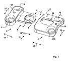
- Fig. 1 the basic principle of the plate implant 1 is shown.
- This plate implant 1 consists of a first plate component 2 and a further plate component 3.
- the two plate components 2, 3 are designed differently.
- the first plate component 2 has holes 4 for fixing screws not shown yet. Furthermore, a connecting means 5 is provided, which cooperates with a receiving means 6 of the further second plate component 3.
- the connecting means 5 is designed tongue-like and is formed in its cross section smaller than the remaining part of the plate component 2. Also, the thickness of the connecting means 5 is less than the remaining part of the plate component. 1
- this bore 8 is provided in the area of the free end 7 of the connecting means 5.
- this bore 8 also has an internal thread 9.
- the first plate component 2 is bent both in the direction of the transverse extension 10 and in the direction of the longitudinal extent 11, so that adaptation to vertebral bodies or to bones can take place.
- the tongue-like connecting means 5 is designed to cooperate with the receiving part 6 of the second plate component 3.
- the second plate component 3 as receiving means 6 within the main body of the second plate component 3, a recess 12 which is formed such that the tongue-like connecting means 5 can be inserted in the direction of arrow 13 in the receiving means 6.
- a dovetail guide is provided for the exact, virtually play-free guidance.
- the tongue-like connecting means 5 is designed such that it is not designed to be flush with the underside of the plate components 2, 3 on the side facing the vertebral body or bone. It is a distance provided in order to avoid that during sliding movements of this connecting means 5 slides on the surface of the bone or the vertebral body.
- the second plate component 3 further has a longitudinal bore 14, which is aligned in the inserted state of the first plate component 2 with the bore 8 of the connecting means 5.
- the second plate component 3 also has holes 15 for receiving fastening screws, which in the Fig. 1 so not be shown on.
- Each of the plate components 2, 3 has bores 16 which are substantially smaller in diameter than the remaining bores 4, 15. These bores 16 serve to prevent the position on the bone or the vertebral bodies of the respective plate components 2, 3 before they be pre-fixed with the fixing screws.
- the second plate component 3 is almost square in shape and also has in its longitudinal extension 11 and in the transverse extension 10 each have radii of curvature. In addition, it is also bendable in these directions, so that it is adaptable to the outer contour of vertebral bodies and bones.
- Fig. 2 is the basic principle of the plate implant 1 according to Fig. 1 shown.
- 4 or 15 fixing screws 17 are shown for the holes, which are polyaxially inserted into the holes 4, 15.
- Polyaxial means that these need not be inserted directly perpendicular to the surface of the respective plate component 2, 3, but depending on the givens of the structure they encounter.
- a clamping screw 18 is provided, which is screwed into the thread 9 of the bore 8.
- the clamping screw 18 is designed such that it also has a thread 19 which cooperates with the thread 9 of the bore 8.
- Fig. 3 the operation of the clamping screw 18 is shown in connection with the plate implant 1. It is inserted in assembled plate components 2, 3 in the longitudinal bore 14 of the second plate component 3 and the thread 19 of the clamping screw 18 occurs in connection with the thread 9 of the bore 8 of the connecting means 5.
- the bead 20 occurs with the side edges 22 of the longitudinal bore fourteenth in conjunction such that between the clamping screw 18 and the plate component 3, a first clamping action is formed.
- By screwing the clamping screw 18 in the bore 8 also creates a clamping effect such that the connecting means 5 presses within the recess 12 to the inside of the second plate component 3 and here a clamping action is created.
- the two plate components 2, 3 and the clamping screw 18 are designed such that no blocking of the sliding movement in or against the arrow direction 23 is intended.
- the aim is to achieve a clamping effect, which allows a sliding of the first plate components 2 against the second plate component 3 against a defined force.
- the longitudinal bore 14 may be conical, so that it tapers in the direction of arrow 23. This means that the clamping force increases with increasing settling. This also means that the forces must be greater in order to effect a corresponding displacement in the direction of arrow 23.
- Fig. 4 is the one in the previous one Fig. 1 and Fig. 2 shown basic shape of the plate implant 1 shown in the assembled state.
- the clamping screw 18 cooperates with the side edges 22 of the longitudinal bore 14.
- the representation in Fig. 4 shows the starting position. By settling creates a shift in the direction of arrow 23 and that the maximum distance, which is limited by the distance 24 of a portion of the first plate component 2 to the second plate component 3 or by the distance 25.
- Fig. 5 a plan view of the basic unit of the plate implant 1 is shown.
- the plan view is made on a part of a spinal column 26, which consists of several vertebral bodies 27.
- the first plate component 2 is arranged on a first vertebral body 27, wherein the second plate component 3 is arranged in the subsequent further vertebral body 27.
- the two plate components 2, 3 have a distance 24 which has been chosen freely in order to compensate for a settling of the two vertebral bodies 27.
- the clamping screw 18 is arranged within the longitudinal bore 14 so that it is arranged on the side facing the first plate component 2 side, so that a displacement of the first plate components 2 relative to the second plate component 3 opposite to the direction of arrow 23 or a displacement of the second plate component 3 relative to the first Plate component 2 in the direction of arrow 23 is possible.
- settling has occurred and the two plate components 2, 3 have moved towards each other.
- the clamping screw 18 has slid within the longitudinal bore 14 and arrived at its end position.
- the vertebral bodies 27 are in this position very close to each other, so that it is further ensured that the power flow does not take place via the plate implant 1, but via the vertebral body itself.
- the plate implant 1 also retains its strength with respect to the vertebral body 27, since the forces do not act on the fastening screws 17.
- FIG. 7 Several perspective views are shown on an extension plate 28.
- An extension plate also consists again of a nearly rectangular base body, on one side of which a connecting means. 5 extends.
- This connecting means 5 is designed in such a way as already in accordance with the first plate component 2 Fig. 1 is provided. It is tongue-like and has at its end a bore 8 with an internal thread 9.
- the main body 28 of the extension plate on two holes 29, which serve to receive the fastening screws not shown in detail in the drawing.
- a longitudinal bore 14 is provided in the main body. This longitudinal bore corresponds to the longitudinal bore 14, as it is already known from the second plate component 3. It also has an elongate recess and a defined side flank 22.
- the extension plate 28 has a receiving means 6. This receiving means 6 is designed as it is already known from the second plate component 3. It serves to receive the connecting means 5.
- Fig. 8 shows in a perspective view of the application of such an extension plate 28.
- the extension plate 28 is inserted in the formation of a chain link between the first plate component 2 and the second plate component 3.
- a plate implant 1 is formed.
- a plurality of such extension plates 28 can be inserted, whereby it must always be ensured that both a first plate component 2 and a second plate component 3 must be present at the beginning or at the end of the "chain”. These two plate components 2, 3 form the conclusion of the "chain”.
- Fig. 9 is that according to Fig. 8 shown plate implant 1 together with the expansion plate 28 in addition with fastening screws 17 and also clamping screws 18 shown.
- Each of the plate elements has at least two holes 4, 15, 29 into which the fastening screws 17 can be inserted polyaxially.
- FIG. 10 and Fig. 11 is the assembly and the representation of an embodiment of a plate implant 1, as shown in Fig. 8 and Fig. 9 has already been explained.
- FIG. 10 shown view is a sliding movement reproduced in an unrestricted form.
- the clamping screw 18 is screwed in, such that the screw head of the clamping screw 18 cooperates with the side edge 22 of the longitudinal bore 14.
- the resulting clamping forces F are exemplified for all embodiments of the interaction of the clamping screw 18 with the respective longitudinal bores 14.
- the clamping forces F K which exerts the clamping screw 18 against the side edges 22 of the longitudinal bore 14.
- clamping forces F P which occur by screwing the clamping screw 18 into the bore 8 of the connecting means 5. Due to the fact that the screw head of the clamping screw 18 rests against the side flanks 22 of the longitudinal bore, the connecting means 5 is used on the inside of the receiving means 6, so that a flat contact occurs. This creates the additional clamping force F P.
- a plate implant 1 which consists of the respective first plate component 2 and the second plate component 3 and three extension plates 28.
- the spacings of the extension plates 28 are selected such that the fastening screws 17 find optimal support in the vertebral bodies 27 of the spine 26 shown here. This results between the individual plates, a distance 24, which is needed to compensate for the so-mentioned settling.
- Fig. 14 is shown a perspective view of the clamping screw 18, as has already been used in the previous figures.
- the clamping screw essentially has two areas, namely a first area of a screw head and another area, namely the area of a screw thread.
- the area of the screw thread comprises a thread 19, which is usually commercially available. However, it can also be a fine thread, so that even with low revolutions corresponding clamping forces can be obtained.
- the screw head is specially designed. It has a circumferential bead 20, which is at least equal to the screw thread in its diameter. Preferably, the screw head is larger than the thread 19.
- the bead 20 has a certain thickness. The thickness is designed such that it is circumferentially the same design. However, it has a slight slope 21, such that the slope from the side facing away from the thread 19 to the side facing the thread 19 tilts.
- the clamping screw 18 has a rotating means.
- the rotating means is an Allen body, which can be easily inserted into the screw head. It creates after insertion a positive and positive fit, so that the corresponding rotational movement or the corresponding torque can be applied.
- Fig. 15 shows a cross section through a plate implant 1.
- the cross section is representative of all embodiments of the inventive plate implant 1, both for the basic equipment, which consists of a first and second plate component 2, 3 as well as for the embodiments having one or more extension plates 28 ,
- the connection between the individual plate elements is always the same. It usually consists of a connecting means 5, which is guided in a receiving means 6. Preferably, a corresponding clearance is provided laterally, so that an easy guidance of the connecting means 5 within the receiving means 6 is possible.
- the cross section according to Fig. 15 now shows the main body of either the second plate component 3 or an extension plate 28. In this base body, the connecting means 5 is already inserted and guided so far that the holes 8 of the connecting means 5 is aligned with the longitudinal bore 14 of the body.
- clamping screw 18 is already inserted into the base body.
- the clamping screw 18 is completely screwed with its thread 19 in the bore 8, which has a corresponding thread 9.
- the side surfaces 21 of the clamping screw 18 are already on the side edges 22 of the longitudinal bore 14.
- Fig. 16 is an enlarged view of the Fig. 15 shown. Across from Fig. 15 In addition, the clamping forces are shown, which act when screwed clamping screw 18.
- the first clamping force which occurs is that which is caused by the fact that the clamping screw is screwed in and is in connection with the connecting means 5.
- the connecting means 5 is pressed directly to the inside of the receiving means 6, whereby clamping forces F P arise.
- Another clamping force arises because the bevel 21 of the clamping screw 18 cooperates with the side flank 22 of the longitudinal bore 14.
- the side edge is slightly on the side facing away from the thread 19 in flight, so that already arises due to a Klemmuringmaschinen wedge effect.
- clamping forces F K occur.
- the clamping forces F K are almost equal.
- the longitudinal bore 14 is configured conically, the clamping forces increase with increasing reaching of the stop (travel limit of the sliding movement).
- a plate implant Due to the inventive design of the plate implant, the at least from a first plate component and a second plate component but preferably from between the first plate component and the second plate component is comprised of extension plates connected therebetween, a plate implant has been provided which is universally applicable in the application of osteosynthesis.
- this plate implant is characterized by compensating the so-called settling that occurs in the regression of stiffened bone elements, so that the force flow that is normally absorbed by the bone is also transmitted via the bones, so that a functional overload of the plate implant is avoided.
Landscapes
- Health & Medical Sciences (AREA)
- Orthopedic Medicine & Surgery (AREA)
- Life Sciences & Earth Sciences (AREA)
- Surgery (AREA)
- Neurology (AREA)
- Heart & Thoracic Surgery (AREA)
- General Health & Medical Sciences (AREA)
- Biomedical Technology (AREA)
- Nuclear Medicine, Radiotherapy & Molecular Imaging (AREA)
- Medical Informatics (AREA)
- Molecular Biology (AREA)
- Animal Behavior & Ethology (AREA)
- Engineering & Computer Science (AREA)
- Public Health (AREA)
- Veterinary Medicine (AREA)
- Oral & Maxillofacial Surgery (AREA)
- Pathology (AREA)
- Surgical Instruments (AREA)
- Prostheses (AREA)
Description
Die Erfindung bezieht sich auf ein Plattenimplantat, das in seiner Grundausstattung aus einer ersten und einer zweiten Plattenkomponente besteht. Die erste Plattenkomponente weist Bohrungen zur Aufnahme von Befestigungsschrauben und einem Verbindungsmittel auf. Die weitere zweite Plattenkomponente zeigt ein Aufnahmemittel zur Aufnahme eines Verbindungsmittels und Bohrungen zur Aufnahme von Befestigungsschrauben. Jede der Plattenkomponenten ist bezüglich der anderen Plattenkomponente in eine Richtung gleitend gelagert und die Plattenkomponenten sind mit einer Vorrichtung versehen, die ihren Gleitlauf zueinander begrenzen.The invention relates to a plate implant, which consists in its basic configuration of a first and a second plate component. The first plate component has holes for receiving fastening screws and a connecting means. The further second plate component shows a receiving means for receiving a connecting means and holes for receiving fastening screws. Each of the plate components is slidably mounted in one direction with respect to the other plate component, and the plate components are provided with means limiting their sliding to one another.
Die Osteosynthese ist ein Verfahren, das zur Versorgung von Knochenbrüchen und anderen Knochenverletzungen dient, bei denen insbesondere Implantate, die meistens aus Metall bestehen, eingesetzt werden. Ziel ist es dabei, die Fixierung der zueinander gehörigen Knochenfragmente in einer normalen Stellung (Reposition) zu fixieren. In der Regel erfolgt die operative Versorgung durch das Anbringen von Metallplatten und Befestigungsschrauben am Knochen oder, besonders bei Frakturen des Schaftes der grossen Röhrenknochen, durch Einbringung von langen Nägeln, die in der Markhöhle entlang der Achse des Knochens gelagert werden.Osteosynthesis is a procedure that is used to treat bone fractures and other bone injuries, in particular implants, which are mostly made of metal, are used. The aim is to fix the fixation of the related bone fragments in a normal position (reduction). Typically, surgical care is provided by attaching metal plates and screws to the bone, or, especially fractures of the shaft of the large bones, by inserting long nails that are stored in the medullary canal along the axis of the bone.
Insbesondere sind bei der Knochenzusammenführung im Bereich der Halswirbelsäule spezielle Techniken bekannt. Sie werden üblicherweise bei Krankheitsbildern, die auf ein HWS (Halswirbelsäulen) - Syndrom zurückzuführen sind, aber auch bei einem degenerativen Rückgrat eingesetzt. Die bei HWS-Syndromen angewandten Techniken stützen sich darauf, dass operativ die so genannte craniocervikale Instabilität durch Einfügen von Plattenimplantaten verringert beziehungsweise beseitigt wird. Hierzu werden plattenartige Elemente, die mehrere Bohrungen zur Aufnahme von Befestigungsschrauben umfassen, auf die dem Körper abgewandten Seite der Wirbelsäule angebracht, sodass mit den Befestigungsschrauben mehrere aufeinander folgende Wirbelkörper miteinander verbunden werden.In particular, special techniques are known in bone fusion in the cervical spine. They are commonly used in diseases related to cervical spine syndrome but also in degenerative backbones. The techniques used in cervical spine syndromes rely on reducing or eliminating so-called craniocervical instability by inserting plate implants. For this purpose, plate-like elements, the comprise a plurality of holes for receiving fastening screws, attached to the side facing away from the body of the spine, so that the fastening screws several consecutive vertebral bodies are interconnected.
Insbesondere stellt sich bei der Befestigung des Plattenimplantats die Schwierigkeit, dass in der Regel der Abstand zwischen den aufeinanderfolgenden Wirbelkörpern oft unterschiedlich ist, sodass eine Vielzahl von unterschiedlichen langen Plattenimplantaten in unterschiedlichen Ausgestaltungen bevorratet werden muss.In particular, the difficulty in attaching the plate implant is that, as a rule, the distance between the successive vertebrae is often different, so that a large number of different long plate implants must be stored in different configurations.
Um diesen Umstand zu vermeiden, ist beispielsweise aus der
Aus der
Aus der
Unter dem Begriff "Settling" oder "Sinking" (nachstehend stellvertretend für Settling genannt) ist eine Migration der Knochen beziehungsweise Wirbelkörper zu verstehen, die aufgrund der Nichtbelastung (wegen des Anbringens des Implantats) degenerieren und ihre Lage entsprechend verändern. Bevor ein Plattenimplantat angebracht wird, wird zwischen die Wirbelkörper ein Platzhalter eingelegt. Platzhalter können aus einem körperfremden oder einem körpereigenen (beispielsweise Knochen) Material bestehen. Dieser Platzhalter fixiert sich aufgrund der Kräfte, die auf die Wirbelkörper wirken. Doch wegen dauerhafter axialer und vertikaler Belastung degenerieren die Wirbelkörper und der jeweilige Platzhalter verlässt seine vorgegebene Position. Sinkt der Platzhalter in den Wirbelkörper (aufgrund starker Belastung, Abnutzung, schlechter Qualität des Knochens etc.), so entsteht zwischen den Wirbelkörpern ein Freiraum, da die Wirbelkörper sich nicht mehr aufeinander zu bewegen können, da ihr Abstand zueinander durch die aus dem Stand der Technik bekannten Plattenimplantate fixiert ist. Die axialen und vertikalen Belastungen werden nun nicht mehr über die Wirbelkörper und den Platzhalter geführt, sondern der Kraftfluss wird über das Plattenimplantat geführt.The term "settling" or "sinking" (hereinafter referred to as settling) is a migration of the bones or vertebral bodies to understand that degenerate due to the non-load (because of the attachment of the implant) and change their position accordingly. Before a plate implant is placed, a placeholder is inserted between the vertebral bodies. Wildcards can consist of a foreign body or a body's own (for example, bone) material. This placeholder is fixed due to the forces acting on the vertebral bodies. However, due to permanent axial and vertical load, the vertebral bodies degenerate and the respective placeholder leaves his predetermined position. Decreases the placeholder in the vertebral body (due to heavy load, wear, poor quality of the bone, etc.), it creates a space between the vertebral bodies, since the vertebral bodies can no longer move towards each other, as their distance from each other by the from the state of Technique known plate implants is fixed. The axial and vertical loads are now no longer guided over the vertebral bodies and the placeholder, but the power flow is guided over the plate implant.
Die dabei entstehenden Kräfte aufgrund dieses Settlings- beziehungsweise Sinking-Vorgangs sind derart groß, dass die Befestigungsschrauben, die an sich zur Fixierung der Plattenimplantate vorgesehen sind, sich lösen. Dadurch ist das Implantat nicht mehr funktionsfähig und es können weitere Schäden an Knochen und Wirbelkörpern entstehen. Es besteht auch die Gefahr, dass aufgrund der hohen auftretenden Kräfte das Plattenimplantat bricht. Damit kann die eigentliche Funktion des Plattenimplantats vollständig außer Kraft gesetzt werden.The resulting forces due to this settling or sinking process are so great that the fastening screws, which are intended to fix the plate implants, come off. As a result, the implant is no longer functional and it can cause further damage to bone and Vertebral bodies arise. There is also the danger that the plate implant will break due to the high forces occurring. Thus, the actual function of the plate implant can be completely overridden.
Somit besteht einer der wesentlichen Nachteile der aus dem Stand der Technik bekannten Plattenimplantate darin, dass das sogenannte Settling von den Implantaten nicht berücksichtigt wird.Thus, one of the major disadvantages of the plate implants known from the prior art is that the so-called settling is not taken into account by the implants.
Die Aufgabe der Erfindung ist es, Plattenimplantate gemäß dem Stand der Technik derart weiter zu entwickeln, dass insbesondere das Settling von Knochen beziehungsweise Wirbelkörpern, wenn diese mit einem Plattenimplantat versehen sind, ausgleicht.The object of the invention is to further develop plate implants according to the state of the art such that in particular the settling of bones or vertebral bodies, if they are provided with a plate implant, compensates.
Die vorliegende Erfindung zielt darauf ab, die Nachteile des Standes der Technik durch ein Plattenimplantat nach Anspruch 1 zu vermeiden.The present invention aims to avoid the disadvantages of the prior art by a plate implant according to
Die Erfindung geht einen vollständig anderen Weg, als den, den der Stand der Technik vorschlägt. Aufgrund der aufgeführten Klemmwirkung wird im Gegensatz zum Stand der Technik, bei dem eine vollständige Blockade der Gleitbewegung der Plattenkomponenten nach der Justierung erzielt wird, erreicht, dass durch das Settling eine Verschiebung der beiden Plattenkomponenten zueinander entgegen einer definierten Klemmkraft möglich ist. Die Klemmkraft wird durch da Anzugsmoment der Klemmschraube, aber auch durch die Klemmwirkung, die der Schraubenkopf der Klemmschraube durch Zusammenwirken mit der Längsbohrung erzielt, hervorgerufen.The invention takes a completely different route than that proposed by the prior art. Due to the clamping effect mentioned, in contrast to the prior art, in which a complete blockage of the sliding movement of the plate components is achieved after adjustment, achieved that a settling of the two plate components to each other against a defined clamping force is possible. The clamping force is through Tightening torque of the clamping screw, but also by the clamping action, the screw head of the clamping screw achieved by cooperation with the longitudinal bore, caused.
Damit können sich die Knochen bzw. Wirbelkörper aufeinander zubewegen, wenn der Platzhalter nicht mehr den an sich gedachten Platz aufzeigt. Dadurch verbleibt der Kraftfluss zwischen den Knochen beziehungsweise Wirbelkörpern und verläuft nicht über das Plattenimplantat selbst, wodurch gewährleistet ist, dass die Befestigungsschrauben nicht mit derart hohen Kräften belastet werden, dass eine Lockerung oder sogar eine Loslösung aus dem Knochen beziehungsweise aus den Wirbelkörpern erfolgen kann.This allows the bones or vertebrae to move towards each other when the placeholder no longer indicates the imaginary place itself. As a result, the power flow between the bones or vertebral bodies remains and does not extend over the plate implant itself, which ensures that the fastening screws are not loaded with such high forces that loosening or even detachment from the bone or from the vertebral bodies can take place.
Ein weiterer Vorteil der Erfindung ist es, dass das Plattenimplantat hinsichtlich seiner Führungselemente derart ausgestaltet ist, dass bei Verschiebungen des Plattenimplantats Teile dieses Implantats nicht über den Wirbelkörper bzw. Knochen gleiten. Dadurch werden Irritationen der Knochenhaut vorteilhafterweise vermieden.Another advantage of the invention is that the plate implant is designed with respect to its guide elements such that upon displacements of the plate implant parts of this implant do not slide over the vertebral body or bone. As a result, irritations of the periosteum are advantageously avoided.
Einer der weiteren Vorteile der Erfindung besteht darin, dass das Plattenimplantat aus beliebigem Material herstellbar ist. So ist es zum Beispiel denkbar, dass es neben Titan auch aus spritzgussfähigem Kunststoff herstellbar ist.One of the further advantages of the invention is that the plate implant can be produced from any desired material. So it is conceivable, for example, that it can be produced in addition to titanium also from injection-moldable plastic.
Die Geometrie der Plattenkomponenten ist sehr klein gewählt. Dies bringt den Vorteil mit sich, dass diese einzelnen Plattenkomponenten exakt auf die jeweiligen Wirbelkörper aufgesetzt werden können, ohne dass diese einen Überstand (über die Geometrie des Wirbelkörpers hinaus) bilden. Denn aus dem Stand der Technik ist bekannt, dass insbesondere zu lang gewählte Plattenelemente, die über in den Plattenelementen vorgesehene Langlöcher mit Schrauben befestigt werden, sich beim Settlingvorgang in den benachbarten Wirbelkörper oder in die Bandscheiben schieben und so Sekundärschäden hervorrufen.The geometry of the plate components is chosen very small. This has the advantage that these individual plate components can be placed exactly on the respective vertebral bodies without these forming a supernatant (beyond the geometry of the vertebral body). For it is known from the prior art that, in particular, plate elements which have been selected too long and which are fastened with screws via slots provided in the plate elements, slide into the adjacent vertebral body or into the intervertebral discs during the settling process and thus cause secondary damage.
Vorzugsweise sind Plattenbreiten bis kleiner 22 mm und Plattendicken kleiner als 2,5 mm vorgesehen.Preferably, plate widths are provided to less than 22 mm and plate thicknesses smaller than 2.5 mm.
Zudem bietet das Plattenimplantat der vorliegenden Erfindung gegenüber dem Stand der Technik den Vorteil, dass es vor der Adaption auf Knochen oder Wirbelkörper bereits zusammengefügt werden kann und Fixiermittel umfasst, mittels denen eine einfache und vorläufige Fixierung auf Knochen und Wirbelkörpern möglich ist, um so eine Anpassung der einzelnen Abstände und das Finden der optimalen Anbringung der Befestigungsschrauben auf einfache Art und Weise zu ermöglichen.In addition, the plate implant of the present invention has the advantage over prior art that it can already be assembled prior to adaptation to bone or vertebral bodies and includes fixatives by means of which simple and provisional fixation on bone and vertebral bodies is possible, thus adapting allow the individual distances and finding the optimal attachment of the mounting screws in a simple manner.
Ein weiterer Vorteil der Erfindung besteht darin, dass das Plattenimplantat als Bausatz vorliegt. Unter Zugrundelegung der jeweiligen Plattenkomponenten kann durch Einfügen unterschiedlicher Anzahl von Erweiterungsplatten die Länge des Plattenimplantats je nach Anwendungsfall frei gewählt werden. Dabei bleibt weiterhin die eingeschränkte Gleitbewegung zwischen jeder einzelnen Platte gewährleistet. Die einzelnen Plattenkomponenten und die Erweiterungsplatten weisen trotzdem eine sehr kleine Geometrie auf, so dass die zuvor genannten Sekundärschäden vermieden werden.Another advantage of the invention is that the plate implant is available as a kit. Based on the respective plate components can be chosen freely by inserting different number of extension plates, the length of the plate implant depending on the application. The limited sliding movement between each plate remains guaranteed. Nevertheless, the individual plate components and the extension plates have a very small geometry, so that the aforementioned secondary damage can be avoided.
Die Erweiterungsplatten bestehen vorzugsweise ebenfalls aus einem plattenartigen Grundkörper, der Bohrungen für die Aufnahme von Befestigungsschrauben aufweist. Ferner sind Aufnahmemittel zur Aufnahme eines Verbindungsmittels und ein Verbindungsmittel selbst vorgesehen. Längsbohrungen zur Aufnahme einer weiteren Klemmschraube und zur Begrenzung des Gleitlaufs sind ebenfalls vorgesehen. Damit kann aus mindestens drei unterschiedlichen Plattenkomponenten ein Plattenimplantat definierter Länge hergestellt werden. Der Anwender kann unmittelbar vor Ort entscheiden, welche Länge notwendig ist. Diese kann durch die Anzahl der Erweiterungsplatten bestimmt werden. Dadurch entfällt eine erheblich kostenaufwendige Bevorratung von unterschiedlichen Plattenimplantaten unterschiedlicher Länge.The extension plates preferably also consist of a plate-like base body having holes for receiving fastening screws. Furthermore, receiving means for receiving a connecting means and a connecting means itself are provided. Longitudinal holes for receiving a further clamping screw and to limit the sliding are also provided. This can be made of at least three different plate components a plate implant of defined length. The user can decide directly on site which length is necessary. This can be determined by the number of extension plates. This eliminates a considerably expensive storage of different plate implants of different lengths.
Die Plattenimplantate selbst weisen sowohl in ihrer Längs- als auch in ihrer Querstreckung Krümmungen auf. Zusätzlich sind sie aufgrund ihrer Dicke entsprechend an die Kontur der Knochen bzw. der Wirbelkörper anpassbar, indem sie von dem Anwender entsprechend zurechtgebogen werden können.The plate implants themselves have curvatures both in their longitudinal and in their transverse extent. In addition, due to their thickness, they are adaptable to the contour of the bones or the vertebral bodies by being suitably bent by the user.
Dabei geht aber die Eigenschaft nicht verloren, dass die Verbindungsmittel in den Aufnahmemitteln frei gleiten können, damit das entsprechende Settling nachvollzogen werden kann.However, it is not lost the property that the connecting means can slide freely in the receiving means, so that the corresponding settling can be followed.
Aufgrund der Ausgestaltung der einzelnen Plattenkomponenten beziehungsweise der Erweiterungsplatten ist es für den Anwender möglich, auf sehr einfache Art und Weise die Reihenfolge zur Montage des Plattenimplantats einzuhalten, da es aufgrund der einfachen optischen Struktur von Plattenkomponenten und Erweiterungsplatten ohne weiteres selbsterklärend erfasst werden kann, welche Plattenelemente zusammenzufügen sind.Due to the configuration of the individual plate components or the extension plates, it is possible for the user to follow the sequence for mounting the plate implant in a very simple manner, since it can be readily detected self-explanatory due to the simple optical structure of plate components and extension plates, which plate elements are to be joined together.
Um diesen Vorgang weiter zu unterstützen, sind die einzelnen Plattenelemente farbig ausgestaltet, sodass der Anwender unmittelbar die Reihenfolge von erster Plattenkomponente, mindestens einer Erweiterungsplatte sowie der weiteren Plattenkomponente erfassen und umsetzen kann. Durch ein einfaches Stecksystem können die einzelnen Plattenelemente bereits funktionell miteinander zusammengefügt werden, sodass einzelne Gliederelemente entstehen. Die Funktionsfähigkeit kann bereits beim ersten Einstecken geprüft werden.In order to further support this process, the individual plate elements are colored, so that the user can immediately record and implement the order of the first plate component, at least one extension plate and the other plate component. Thanks to a simple plug-in system, the individual panel elements can already be functionally joined together to form individual sectional elements. The functionality can be checked already at the first insertion.
Durch Vorfixieren der Klemmschraube (noch nicht vollständiges Aufbringen eines Anziehmoments auf die Klemmschraube) bleibt zwar die Gleitbewegung der Plattenelemente untereinander erhalten, ist jedoch in den entsprechenden Bewegungsfreiheiten bereits eingeschränkt. Die vorgesehene Klemmkraft, die zwischen den Plattenelementen wirken soll, wird erst durch ein weiteres Hineindrehen der Klemmschraube in das Verbindungsmittel bewirkt.By pre-fixing the clamping screw (not yet complete application of a tightening torque on the clamping screw), although the sliding movement of the plate elements is maintained with each other, but is already limited in the appropriate freedom of movement. The intended clamping force, which is to act between the plate elements, is effected only by a further screwing in of the clamping screw in the connecting means.
Zusätzliche Bohrungen in den jeweiligen Plattenelementen können dafür vorgesehen werden, auf den Knochen beziehungsweise Wirbelkörpern die Plattenelemente vorzufixieren, damit ein Anbohren der Knochen zur Durchführung der Befestigung des Befestigungsschrauben möglich ist.Additional holes in the respective plate members may be provided to pre-fix the plate members to the bone or vertebral bodies, respectively, to permit bone piercing to effect attachment of the fixation screws.
Die Bohrungen in den einzelnen Plattenelementen sind derart gewählt, dass die Schrauben polyaxial einbringbar sind. Dies bedeutet, dass die Befestigungsschrauben nicht senkrecht zu den einzelnen Plattenelementen eingefügt werden müssen. Sie sind in jedem beliebigen Winkel in den Knochen beziehungsweise in den Wirbelkörper eindrehbar. Vorzugsweise sind Befestigungsschrauben vorgesehen, die selbstsichernd sind. Hierzu können beispielsweise spreizbare Schraubenköpfe vorgesehen sein, sodass ein Klemmen der Schraube mit dem Plattenelement unmittelbar nach dem Fixieren auf dem Knochen beziehungsweise auf den Wirbelkörpern möglich ist.The holes in the individual plate elements are chosen such that the screws are introduced polyaxially. This means that the fixing screws are not inserted perpendicular to the individual plate elements Need to become. They can be screwed into the bone or into the vertebral body at any angle. Preferably, fastening screws are provided which are self-locking. For this purpose, for example, expandable screw heads can be provided, so that a clamping of the screw with the plate element immediately after fixing on the bone or on the vertebral bodies is possible.
Weitere vorteilhafte Ausgestaltungen gehen aus der nachfolgenden Beschreibung, den Ansprüchen sowie den Zeichnungen hervor. Kurze Beschreibung der Abbildungen der Zeichnungen
-
Fig. 1 zeigt eine perspektivische Ansicht auf das Plattenimplantat, bestehend aus einer ersten Plattenkomponente und einer zweiten Plattenkomponente, wobei die beiden Plattenkomponenten nicht miteinander verbunden sind; -
Fig. 2 zeigt eine perspektivische Ansicht auf die inFig. 1 dargestellten Plattenkomponenten jedoch mit Darstellungen der Befestigungsschrauben und der erfindungsgemässen Klemmschraube; -
Fig. 3 zeigt eine perspektivische Ansicht auf ein Plattenimplantat, bestehend aus zwei Plattenkomponenten mit noch nicht fixierter Klemmschraube; -
Fig. 4 zeigt eine perspektivische Ansicht auf das montierte Plattenimplantat gemässFig. 3 , jedoch mit montierter Klemmschraube; -
Fig. 5 zeigt eine Draufsicht auf ein montiertes Plattenimplantat bestehend aus zwei Plattenkomponenten im Bereich der Halswirbelsäule im nicht-gesettleten Zustand; -
Fig. 6 zeigt eine Draufsicht auf ein montiertes Plattenimplantat, bestehend aus zwei Plattenkomponenten im Bereich der Halswirbelsäule im gesettleten Zustand; -
Fig. 7 zeigt drei perspektivische Ansichten auf ein Erweiterungselement; -
Fig. 8 zeigt eine perspektivische Ansicht eines Ausführungsbeispiels eines Plattenimplantats bestehend aus zwei Plattenkomponenten sowie einer Erweiterungsplatte; -
Fig. 9 zeigt eine perspektivische Darstellung der Plattenkomponenten mit der Erweiterungsplatte zusammen mit Befestigungsschrauben und Klemmschrauben; -
Fig. 10 zeigt eine perspektivische Ansicht auf ein zusammengefügtes Plattenimplantat bestehend aus zwei Plattenkomponenten und einer Erweiterungsplatte mit noch nicht eingefügten Klemmschrauben; -
Fig. 11 zeigt eine perspektivische Ansicht auf ein zusammengefügtes Plattenimplantat bestehend aus zwei Plattenkomponenten und einer Erweiterungsplatte mit eingefügten Klemmschrauben; -
Fig. 12 zeigt eine Draufsicht auf ein montiertes Plattenimplantat bestehend aus zwei Entplatten und drei Erweiterungsplatten, montiert im Bereich eines Halswirbels im nicht gesettleten Zustand; -
Fig. 13 zeigt eine andere perspektivische Ansicht auf ein montiertes Plattenimplantat, bestehend aus zwei Entplatten und drei Erweiterungsplatten, montiert im Bereich eines Halswirbels im nicht- gesettleten Zustand; -
Fig. 14 zeigt eine perspektivische Ansicht auf die Klemmschraube; -
Fig. 15 zeigt einen Schnitt durch ein Plattenimplantat im Bereich der Klemmschraube; -
Fig. 16 zeigt eine vergrösserte Darstellung des Klemmbereichs gemässFig. 15 -
Fig. 17 zeigt eine weitere vergrösserte Darstellung des Klemmbereichs im Bereich der Längsbohrung.
-
Fig. 1 shows a perspective view of the plate implant, consisting of a first plate component and a second plate component, wherein the two plate components are not connected to each other; -
Fig. 2 shows a perspective view of the inFig. 1 However, plate components shown with representations of the mounting screws and the inventive clamping screw; -
Fig. 3 shows a perspective view of a plate implant, consisting of two plate components with not yet fixed clamping screw; -
Fig. 4 shows a perspective view of the mounted plate implant according toFig. 3 , but with mounted clamping screw; -
Fig. 5 shows a plan view of a mounted plate implant consisting of two plate components in the cervical spine in the non-gesettleten state; -
Fig. 6 shows a plan view of a mounted plate implant, consisting of two plate components in the cervical spine in gesettleten state; -
Fig. 7 shows three perspective views of an extension element; -
Fig. 8 shows a perspective view of an embodiment of a plate implant consisting of two plate components and an extension plate; -
Fig. 9 shows a perspective view of the plate components with the expansion plate together with mounting screws and clamping screws; -
Fig. 10 shows a perspective view of an assembled plate implant consisting of two plate components and an extension plate with not yet inserted clamping screws; -
Fig. 11 shows a perspective view of an assembled plate implant consisting of two plate components and an extension plate with inserted clamping screws; -
Fig. 12 shows a plan view of a mounted plate implant consisting of two Entplatten and three extension plates mounted in the region of a cervical vertebra in ungletted state; -
Fig. 13 shows another perspective view of a mounted plate implant, consisting of two disc plates and three extension plates mounted in the region of a cervical vertebra in the non-gesettleten state; -
Fig. 14 shows a perspective view of the clamping screw; -
Fig. 15 shows a section through a plate implant in the region of the clamping screw; -
Fig. 16 shows an enlarged view of the clamping area according toFig. 15 -
Fig. 17 shows a further enlarged view of the clamping area in the region of the longitudinal bore.
In
Die erste Plattenkomponente 2 weist Bohrungen 4 für noch nicht näher dargestellte Befestigungsschrauben auf. Ferner ist ein Verbindungsmittel 5 vorgesehen, das mit einem Aufnahmemittel 6 der weiteren zweiten Plattenkomponente 3 zusammenwirkt. Das Verbindungsmittel 5 ist zungenartig ausgestaltet und ist in seinem Querschnitt geringer ausgebildet als der übrige Teil der Plattenkomponente 2. Auch die Dicke des Verbindungsmittels 5 ist geringer als der übrige Teil der Plattenkomponente 1.The
Im Bereich des freien Endes 7 des Verbindungsmittels 5 ist eine Bohrung 8 vorgesehen. Vorzugsweise weist diese Bohrung 8 auch ein Innengewinde 9 auf.In the area of the
Die erste Plattenkomponente 2 ist sowohl in Richtung der Quererstreckung 10 als auch in Richtung der Längserstreckung 11 gebogen, sodass eine Anpassung an Wirbelkörper oder an Knochen erfolgen kann.The
Wie bereits ausgeführt, ist das zungenartig ausgebildete Verbindungsmittel 5 auf das Zusammenwirken mit den Aufnahmeteil 6 der zweiten Plattenkomponente 3 ausgestaltet. Hierzu weist die zweite Plattenkomponente 3 als Aufnahmemittel 6 innerhalb des Grundkörpers der zweiten Plattenkomponente 3 eine Aussparung 12 auf, die derart ausgebildet ist, dass das zungenartige Verbindungsmittel 5 in Pfeilrichtung 13 in das Aufnahmemittel 6 eingeführt werden kann. Vorzugsweise ist zur exakten, nahezu spielfreien Führung eine Schwalbenschwanzführung vorgesehen. Das zungenartige Verbindungsmittel 5 ist derart ausgelegt, dass es auf der zum Wirbelkörper bzw. Knochen hinweisenden Seite nicht fluchtend mit der Unterseite der Plattenkomponenten 2, 3 ausgelegt ist. Es ist ein Abstand vorgesehen, um zu vermeiden, dass bei Gleitbewegungen dieses Verbindungsmittel 5 auf der Oberfläche des Knochens bzw. des Wirbelkörpers gleitet.As already stated, the tongue-like connecting means 5 is designed to cooperate with the receiving part 6 of the
Die zweite Plattenkomponente 3 weist ferner eine Längsbohrung 14 auf, die im eingeschobenen Zustand der ersten Plattenkomponente 2 mit der Bohrung 8 des Verbindungsmittels 5 fluchtend ist.The
Ferner weist die zweite Plattenkomponente 3 ebenfalls Bohrungen 15 zur Aufnahme von Befestigungsschrauben, die in der
Die zweite Plattenkomponente 3 ist in ihrer Form nahezu quadratisch ausgebildet und weist auch in ihrer Längserstreckung 11 als auch in der Quererstreckung 10 jeweils Krümmungsradien auf. Zusätzlich ist sie in diesen Richtungen ebenfalls biegbar, sodass sie an die Aussenkontur von Wirbelkörpern und Knochen anpassbar ist.The
In
Zusätzlich ist eine Klemmschraube 18 vorgesehen, die in das Gewinde 9 der Bohrung 8 eindrehbar ist. Die Klemmschraube 18 ist derart ausgebildet, dass sie ebenfalls ein Gewinde 19 aufweist, das mit dem Gewinde 9 der Bohrung 8 zusammenwirkt. Zusätzlich weist die Klemmschraube 18 im Bereich ihres Schraubenkopfes einen Wulst 20 auf, der vorzugsweise breiter gestaltet ist, als der übrige Teil des Gewindes 19. Dieser Wulst 20 weist eine nach Aussen hin verlaufende Schräge 21 auf, sodass der Durchmesser der Klemmschraube 18 von dem Gewinde 19 wegweisend grösser wird.In addition, a clamping
In
In der in
Vorzugsweise bei einem anderen Ausführungsbeispiel kann auch die Längsbohrung 14 konisch ausgestaltet sein, sodass sie sich in Pfeilrichtung 23 verjüngt. Dies bedeutet, dass die Klemmkraft mit zunehmenden Settling grösser wird. Dies bedeutet auch, dass die Kräfte grösser sein müssen, um eine entsprechende Verschiebung in Pfeilrichtung 23 zu bewirken.Preferably, in another embodiment, the
In
In
Wie in
In
In
In den
In der in
In
Nachstehend wird die Funktionsweise der Klemmwirkung des Plattenimplantats 1 gezeigt. Insbesondere wird näher auf die Wirkung der Klemmschraube 18 im Zusammenwirken mit dem Verbindungsmittel 5 und dem Aufnahmemittel 6 eingegangen.The operation of the clamping action of the
In
Der Schraubenkopf ist speziell ausgestaltet. Er weist einen umlaufenden Wulst 20 auf, der in seinem Durchmesser zumindest gleich dem Schraubengewinde ist. Vorzugsweise ist der Schraubenkopf grösser als das Gewinde 19. Der Wulst 20 weist eine gewisse Dicke auf. Die Dicke ist derart ausgestaltet, dass sie umlaufend gleich ausgestaltet ist. Sie weist jedoch eine geringfügige Schräge 21 auf, derart, dass sich die Schräge von der dem Gewinde 19 abgewandten Seite zu der dem Gewinde 19 zugewandten Seite hin neigt.The screw head is specially designed. It has a
Ferner weist die Klemmschraube 18 ein Drehmittel auf. Bei dem hier ausgeführten Ausführungsbeispiel ist das Drehmittel ein Inbus-Körper, der auf einfache Art und Weise in den Schraubenkopf eingeführt werden kann. Es entsteht nach dem Einführen ein Kraft- und Formschluss, sodass die entsprechende Drehbewegung beziehungsweise das entsprechende Drehmoment aufgebracht werden kann.Furthermore, the clamping
Ferner ist bereits die Klemmschraube 18 in den Grundkörper eingeführt. Die Klemmschraube 18 ist vollständig mit seinem Gewinde 19 in die Bohrung 8, das ein entsprechendes Gewinde 9 aufweist, eingedreht. Die Seitenflächen 21 der Klemmschraube 18 liegen bereits an den Seitenflanken 22 der Längsbohrung 14 an.Furthermore, the clamping
In
Aufgrund der auftretenden Klemmkräfte FK, FP entsteht somit eine doppelte Sicherheit. Die auftretenden Klemmkräfte sind zudem in unterschiedliche Richtungen ausgerichtet, so dass diese sich nicht gegenseitig kompensieren können.Due to the occurring clamping forces F K , F P thus creates a double security. The occurring clamping forces are also aligned in different directions, so that they can not compensate each other.
Durch geeignete Materialauswahl und der entsprechenden Auswahl der Oberflächen kann erreicht werden, dass keine Blockierung der möglichen Gleitbewegung erfolgt, sondern dass ständig gegen die ausgewählte Klemmkraft ein Gleiten des Verbindungsmittels innerhalb des Aufnahmemittels möglich ist.By suitable choice of material and the appropriate choice of surfaces can be achieved that no blocking of the possible sliding movement takes place, but that constantly against the selected clamping force sliding of the connecting means within the receiving means is possible.
Aufgrund der erfindungsgemässen Ausgestaltung des Plattenimplantats, das mindestens aus einer ersten Plattenkomponente und einer zweiten Plattenkomponente vorzugsweise aber aus zwischen der ersten Plattenkomponente und der zweiten Plattenkomponente dazwischen geschalteten Erweiterungsplatten besteht, ist ein Plattenimplantat geschaffen worden, das universell bei der Anwendung der Osteosynthese einsetzbar ist. Dieses Plattenimplantat zeichnet sich insbesondere dadurch aus, dass es das so genannte Settling, das bei der Rückbildung von versteiften Knochenelementen eintritt, ausgleicht, sodass der Kraftfluss, der normalerweise von den Knochen aufgenommen wird, auch über die Knochen weiterhin übertragen wird, sodass eine funktionelle Überbelastung des Plattenimplantats vermieden wird.Due to the inventive design of the plate implant, the at least from a first plate component and a second plate component but preferably from between the first plate component and the second plate component is comprised of extension plates connected therebetween, a plate implant has been provided which is universally applicable in the application of osteosynthesis. In particular, this plate implant is characterized by compensating the so-called settling that occurs in the regression of stiffened bone elements, so that the force flow that is normally absorbed by the bone is also transmitted via the bones, so that a functional overload of the plate implant is avoided.
Durch die einfache Ausgestaltung und das Baukastenprinzip ist es möglich, Plattenimplantate unterschiedlicher Länge und Grösse auszuwählen. Durch einfaches Ineinanderfügen ist ein Vorfixieren ohne Probleme und ohne grösseren Aufwand möglich, sodass für den Anwender ein Anpassen, insbesondere im Bereich des Halswirbels auf sehr einfache Art und Weise vonstatten gehen kann.Due to the simple design and the modular principle, it is possible to select plate implants of different length and size. By simply nesting a Vorfixieren without problems and without much effort is possible, so that the user can go customizing, especially in the field of cervical vertebrae in a very simple manner.
- 1 :1 :
- Plattenimplantatplate implant
- 2 :2:
- erste Plattenkomponentefirst plate component
- 3 :3:
- zweite Plattenkomponentesecond plate component
- 4 :4:
- Bohrungdrilling
- 5 :5:
- Verbindungsmittelconnecting means
- 6 :6:
- Aufnahmemittelreceiving means
- 7 :7:
-
freies Ende des Verbindungsmittels 5free end of the connecting
means 5 - 8 :8th :
- Bohrungdrilling
- 9 :9:
- Innengewindeinner thread
- 10 :10:
- Quererstreckungtransverse extension
- 11 :11:
- Längserstreckunglongitudinal extension
- 12 :12:
- Aussparungrecess
- 13 :13:
- Pfeilrichtungarrow
- 14 :14:
- Längsbohrunglongitudinal bore
- 15 :15:
- Bohrungdrilling
- 16 :16:
- Bohrungdrilling
- 17 :17:
- Befestigungsschraubefixing screw
- 18 :18:
- Klemmschraubeclamping screw
- 19 :19:
- Gewinde (der Klemmschraube)Thread (the clamping screw)
- 20 :20:
- Wulstbead
- 21 :21:
- Schrägeslope
- 22 :22:
- Seitenflankeside flank
- 23 :23:
- Pfeilrichtungarrow
- 24 :24:
- Abstanddistance
- 25 :25:
- Abstanddistance
- 26 :26:
- Wirbelsäulespinal column
- 27 :27:
- Wirbelkörpervertebra
- 28 :28:
- Erweiterungsplatteextension plate
- 29 :29:
- Bohrungdrilling
Claims (7)
- A plate implant for use in osteosynthesis comprising at least one first plate component (2) having bores (4) for receiving fixing screws (17) and a connecting means (5), at least one second plate component (3) having bores (4) for receiving fixing screws (17) and a receiving means (6) for receiving the connecting means (5), wherein each plate component (2, 3) can slide with respect to the other plate component (2, 3) in a direction (23) and wherein the plate components (2, 3) are provided with a device which limits their sliding movement relative to each other and includes a clamping screw (18) and a longitudinal bore (14) which is provided in the second plate component (3), wherein the clamping screw (18) comprises a screw thread (19) and a screw head and in the assembled condition of the two plate components (2, 3) the screw thread (19) cooperates with the connecting means (5) and the screw head with the longitudinal bore (14) in such a way that a first clamping action is produced between the screw head and the longitudinal bore (14) and a second clamping action is produced between the connecting means (5) and the receiving means (6), wherein the two plate components (2, 3) and the clamping screw (18) are so designed that in the limits of the sliding movement no blocking of the sliding movement is effected in or in opposite relationship to the direction (23) and the screw head of the clamping screw (18) has a bead (20) which cooperates with the side flanks (22) of the longitudinal bore (14) in such a way that said first clamping action is produced and thereby a clamping force is produced between the clamping screw (18) and the second plate component (3).
- A plate implant according to claim 1 characterised in that at least one extension plate (28) is provided between the first plate component (2) and the second plate component (2, 3), wherein the extension plate (28) has bores for receiving fixing screws (29), a receiving means (6) for receiving a connecting means (5), a connecting means (5) and a longitudinal bore (14) for receiving a further clamping screw (18) and for limiting the sliding movement.
- A plate implant according to claim 2 characterised in that the plate components (2, 3) and the extension plate (28) are of plastic.
- A plate implant according to claim 2 characterised in that the plate components (2, 3) and the extension plate (28) have a curvature both in their longitudinal extent (11) and also in the transverse extent (10).
- A plate implant according to claim 2 characterised in that the plate components (2, 3) and/or the extension plate (28) has additional bores (16) for fixing the plate implant (1).
- A plate implant according to claim 1 characterised in that the connecting means (5) is tongue-like and on the side facing towards the bone is designed in non-aligned relationship with the underside of the plate components (2, 3).
- A plate implant according to one of the preceding claims characterised in that the bead (20) has an inclined portion (21) such that the inclined portion (21) is inclined inwardly from the side remote from the thread (19) to the side facing towards the thread (19).
Applications Claiming Priority (2)
| Application Number | Priority Date | Filing Date | Title |
|---|---|---|---|
| DE202007001585U DE202007001585U1 (en) | 2007-01-30 | 2007-01-30 | Plate implant for use during osteosynthesis, has thread and head cooperating with connecting unit and longitudinal borehole respectively, such that effect is produced between head and borehole and between connecting and retainer units |
| PCT/DE2008/000100 WO2008092422A1 (en) | 2007-01-30 | 2008-01-22 | Plate-implant, in particular for use on a spinal column |
Publications (2)
| Publication Number | Publication Date |
|---|---|
| EP2114274A1 EP2114274A1 (en) | 2009-11-11 |
| EP2114274B1 true EP2114274B1 (en) | 2015-04-15 |
Family
ID=38056472
Family Applications (1)
| Application Number | Title | Priority Date | Filing Date |
|---|---|---|---|
| EP08706779.9A Not-in-force EP2114274B1 (en) | 2007-01-30 | 2008-01-22 | Plate-implant, in particular for use on a spinal column |
Country Status (13)
| Country | Link |
|---|---|
| US (1) | US8821552B2 (en) |
| EP (1) | EP2114274B1 (en) |
| JP (1) | JP2010516413A (en) |
| KR (1) | KR101212402B1 (en) |
| CN (1) | CN101594834B (en) |
| BR (1) | BRPI0807191A2 (en) |
| CA (1) | CA2667605C (en) |
| DE (2) | DE202007001585U1 (en) |
| ES (1) | ES2542151T3 (en) |
| MX (1) | MX2009006038A (en) |
| RU (1) | RU2444322C2 (en) |
| WO (1) | WO2008092422A1 (en) |
| ZA (1) | ZA200902666B (en) |
Families Citing this family (33)
| Publication number | Priority date | Publication date | Assignee | Title |
|---|---|---|---|---|
| US20050049595A1 (en) * | 2003-09-03 | 2005-03-03 | Suh Sean S. | Track-plate carriage system |
| US7909860B2 (en) | 2003-09-03 | 2011-03-22 | Synthes Usa, Llc | Bone plate with captive clips |
| US7857839B2 (en) | 2003-09-03 | 2010-12-28 | Synthes Usa, Llc | Bone plate with captive clips |
| JP5631736B2 (en) * | 2007-10-12 | 2014-11-26 | ジンテス ゲゼルシャフト ミット ベシュレンクテル ハフツング | Reconstruction equipment |
| EP2224868B1 (en) * | 2007-11-21 | 2014-07-30 | Globus Medical, Inc. | Cervical spine stabilization system with extendable plates |
| US9345517B2 (en) | 2008-02-02 | 2016-05-24 | Globus Medical, Inc. | Pedicle screw having a removable rod coupling |
| JP2012502760A (en) * | 2008-09-18 | 2012-02-02 | ジンテス ゲゼルシャフト ミット ベシュレンクテル ハフツング | Anterior transpedicular screw-plate system |
| US8808333B2 (en) | 2009-07-06 | 2014-08-19 | Zimmer Gmbh | Periprosthetic bone plates |
| US20130012992A1 (en) * | 2009-10-26 | 2013-01-10 | Nasser Ani | Apparatus for compressing or decompressing a spinal disc and method of use thereof |
| US9095387B2 (en) * | 2011-04-13 | 2015-08-04 | Globus Medical, Inc. | Spine stabilization |
| WO2012172517A1 (en) | 2011-06-17 | 2012-12-20 | Miami Device Solutions, Llc | Modular bone plate and connector piece for a modular bone plate |
| US11123117B1 (en) * | 2011-11-01 | 2021-09-21 | Nuvasive, Inc. | Surgical fixation system and related methods |
| RU2512785C2 (en) * | 2011-12-21 | 2014-04-10 | Общество с ограниченной ответственностью предприятие "Репер-НН" | Repair plate for posttraumatic defects and deformities of eye grounds |
| US9113968B2 (en) * | 2013-01-28 | 2015-08-25 | Nextremity Solutions, Inc. | Dynamic bone plate compression device and method |
| US9028498B2 (en) * | 2013-03-14 | 2015-05-12 | Innovasis, Inc. | Modular bone fixation plate assembly |
| JP6456939B2 (en) | 2013-07-09 | 2019-01-23 | デピュイ・シンセス・プロダクツ・インコーポレイテッド | Bone fixation system |
| US8915027B1 (en) * | 2013-09-27 | 2014-12-23 | James A. Alfieri, III | Edging system for unit pavement system |
| US10060081B2 (en) | 2013-09-27 | 2018-08-28 | James A. Alfieri, III | Edging system for unit pavement system |
| WO2015065915A1 (en) | 2013-10-28 | 2015-05-07 | Jace Medical, Llc | Orthopaedic fixation devices, systems and methods |
| WO2015112991A1 (en) * | 2014-01-27 | 2015-07-30 | Dallis James | Implantable medical device for restoring alignment and stabilizing bone fractures |
| ES2804126T3 (en) * | 2014-02-24 | 2021-02-03 | Univ Curtin Tech | Bra |
| CN104224291A (en) * | 2014-05-23 | 2014-12-24 | 上海市浦东新区周浦医院 | Novel combined-type calcaneal-fracture internal fixation steel plate |
| WO2015187123A1 (en) * | 2014-06-02 | 2015-12-10 | Albany Medical College | Dynamic decompressive craniotomy fixation devices and related methods |
| US10226290B2 (en) | 2014-08-20 | 2019-03-12 | Jace Medical, Llc | Implant positioning devices and methods |
| US9615931B2 (en) * | 2015-03-20 | 2017-04-11 | Globus Medical, Inc. | Surgical plate systems |
| AU2017311669B2 (en) | 2016-08-16 | 2022-08-25 | DePuy Synthes Products, Inc. | Bone fixation system |
| EP3320867B1 (en) | 2016-11-14 | 2021-08-04 | Biedermann Technologies GmbH & Co. KG | Modular bone plate and member of such a modular bone plate |
| DE102016124528A1 (en) | 2016-12-15 | 2018-06-21 | Karl Leibinger Medizintechnik Gmbh & Co. Kg | Implant for osteosynthesis and implant kit with implant |
| US11000322B2 (en) | 2018-09-20 | 2021-05-11 | DePuy Synthes Products, Inc. | Bone fixation system |
| CN110811803B (en) * | 2019-10-29 | 2021-12-03 | 四川大学华西医院 | Cervical vertebra anterior oblique transverse fixing steel plate |
| CN112773491A (en) * | 2020-09-14 | 2021-05-11 | 江苏强圣医疗科技有限公司 | Bone fracture plate with adjustable size for orthopedics department |
| CN112294501B (en) * | 2020-10-30 | 2021-09-10 | 东南大学 | Adjustable and assembled animal vertebral body fixing instrument |
| US12133667B2 (en) * | 2021-10-22 | 2024-11-05 | Orthopedic Designs North America, Inc. | Self-contouring plate system for bone fractures |
Family Cites Families (14)
| Publication number | Priority date | Publication date | Assignee | Title |
|---|---|---|---|---|
| US5616142A (en) | 1994-07-20 | 1997-04-01 | Yuan; Hansen A. | Vertebral auxiliary fixation device |
| US5916142A (en) * | 1996-10-21 | 1999-06-29 | General Electric Company | Self-aligning swirler with ball joint |
| FR2766353B1 (en) * | 1997-07-28 | 1999-11-26 | Dimso Sa | IMPLANT, ESPECIALLY ANTERIOR CERVICAL PLATE |
| US6238396B1 (en) * | 1999-10-07 | 2001-05-29 | Blackstone Medical, Inc. | Surgical cross-connecting apparatus and related methods |
| FR2810532B1 (en) * | 2000-06-26 | 2003-05-30 | Stryker Spine Sa | BONE IMPLANT WITH ANNULAR LOCKING MEANS |
| US6503250B2 (en) * | 2000-11-28 | 2003-01-07 | Kamaljit S. Paul | Bone support assembly |
| US20050010227A1 (en) * | 2000-11-28 | 2005-01-13 | Paul Kamaljit S. | Bone support plate assembly |
| US20050240187A1 (en) * | 2004-04-22 | 2005-10-27 | Huebner Randall J | Expanded fixation of bones |
| JP4283665B2 (en) * | 2001-06-04 | 2009-06-24 | ウォーソー・オーソペディック・インコーポレーテッド | Dynamic plate for anterior cervical spine with movable segments |
| US7097645B2 (en) * | 2001-06-04 | 2006-08-29 | Sdgi Holdings, Inc. | Dynamic single-lock anterior cervical plate system having non-detachably fastened and moveable segments |
| US6679883B2 (en) * | 2001-10-31 | 2004-01-20 | Ortho Development Corporation | Cervical plate for stabilizing the human spine |
| RU2218123C2 (en) * | 2001-11-20 | 2003-12-10 | Соловьев Валерий Александрович | Adaptive plate for union of bone fractured fragments |
| RU2204957C1 (en) * | 2001-12-29 | 2003-05-27 | Клименко Борис Михайлович | Diaphyseal cover |
| US7169150B2 (en) * | 2003-04-25 | 2007-01-30 | Warsaw Orthopedic, Inc. | Non-metallic orthopedic plate |
-
2007
- 2007-01-30 DE DE202007001585U patent/DE202007001585U1/en not_active Expired - Lifetime
-
2008
- 2008-01-22 BR BRPI0807191-8A2A patent/BRPI0807191A2/en not_active Application Discontinuation
- 2008-01-22 MX MX2009006038A patent/MX2009006038A/en active IP Right Grant
- 2008-01-22 WO PCT/DE2008/000100 patent/WO2008092422A1/en active Application Filing
- 2008-01-22 ES ES08706779.9T patent/ES2542151T3/en active Active
- 2008-01-22 KR KR1020097010779A patent/KR101212402B1/en not_active IP Right Cessation
- 2008-01-22 CA CA2667605A patent/CA2667605C/en not_active Expired - Fee Related
- 2008-01-22 US US12/522,585 patent/US8821552B2/en not_active Expired - Fee Related
- 2008-01-22 DE DE112008000882T patent/DE112008000882A5/en not_active Ceased
- 2008-01-22 JP JP2009547524A patent/JP2010516413A/en active Pending
- 2008-01-22 EP EP08706779.9A patent/EP2114274B1/en not_active Not-in-force
- 2008-01-22 CN CN2008800035658A patent/CN101594834B/en not_active Expired - Fee Related
- 2008-01-22 RU RU2009132550/14A patent/RU2444322C2/en not_active IP Right Cessation
-
2009
- 2009-04-17 ZA ZA2009/02666A patent/ZA200902666B/en unknown
Also Published As
| Publication number | Publication date |
|---|---|
| CN101594834B (en) | 2012-05-30 |
| KR101212402B1 (en) | 2012-12-13 |
| JP2010516413A (en) | 2010-05-20 |
| ES2542151T3 (en) | 2015-07-31 |
| BRPI0807191A2 (en) | 2014-06-03 |
| DE202007001585U1 (en) | 2007-05-10 |
| CA2667605A1 (en) | 2008-08-07 |
| CA2667605C (en) | 2013-02-05 |
| DE112008000882A5 (en) | 2010-01-07 |
| RU2444322C2 (en) | 2012-03-10 |
| KR20090113246A (en) | 2009-10-29 |
| RU2009132550A (en) | 2011-03-10 |
| US20100121328A1 (en) | 2010-05-13 |
| MX2009006038A (en) | 2009-06-17 |
| ZA200902666B (en) | 2010-02-24 |
| CN101594834A (en) | 2009-12-02 |
| EP2114274A1 (en) | 2009-11-11 |
| WO2008092422A1 (en) | 2008-08-07 |
| US8821552B2 (en) | 2014-09-02 |
Similar Documents
| Publication | Publication Date | Title |
|---|---|---|
| EP2114274B1 (en) | Plate-implant, in particular for use on a spinal column | |
| DE69931463T2 (en) | IMPLANT TO REPLACE A SPINE | |
| DE19807236C2 (en) | Intervertebral implant | |
| DE10065398C2 (en) | Length-adjustable placeholder for insertion between two vertebrae | |
| EP1615598B1 (en) | Spondylodesis device | |
| EP2152173B1 (en) | Locking intramedullary nail | |
| EP2621383B1 (en) | Bilateral lamina implant | |
| WO1990000377A1 (en) | Correction and restraining device, in particular for the vertebral column | |
| DE102004009429A1 (en) | Bone anchoring element | |
| EP1481654A1 (en) | Intervertebral fusion implant and instrument for placement and distraction of said implant | |
| DE20320974U1 (en) | Surgical backbone implant is positioned between adjacent vertebrae and consists of two concentric cylinders with interlocking fingers in cruciform array, where the cylinder inner faces bear a thread | |
| EP2457541A1 (en) | Implant between vertebrae | |
| DE29600879U1 (en) | Spinal implant | |
| EP1545357B1 (en) | System for osteosynthesis | |
| EP1833393A1 (en) | Osteosynthesis plate, e.g. a plate for the head of the radius- or humerus, with a plurality of bore holes for receiving bone screws | |
| WO2008075160A1 (en) | Plate implant, in particular for use on a spinal column, with a screw fastener system | |
| WO1990012547A1 (en) | Fixation system for tubular bone fractures | |
| EP1188416B1 (en) | Pedicle screw for intervertebral support element | |
| DE10328307A1 (en) | Vertebral prosthesis | |
| EP1364621B1 (en) | Device for positioning and fixing bone and/or bone fragments | |
| DE102004056091B4 (en) | Orthopedic fixation device and orthopedic fixation system | |
| EP2934355B1 (en) | Lockable intramedullary nail having guide wire holes | |
| DE102007029090A1 (en) | Device for osteosynthesis, particularly bone fracture near joint, has pin for implantation into abarticular bone, and proximal longitudinal ring element provided for implantation into bone fragment near joint | |
| DE102012024687A1 (en) | Lockable intramedullary nail with at least one insert for receiving a locking screw | |
| DE69307946T2 (en) | Transredicular vertebral fixation system and device for carrying it out |
Legal Events
| Date | Code | Title | Description |
|---|---|---|---|
| PUAI | Public reference made under article 153(3) epc to a published international application that has entered the european phase |
Free format text: ORIGINAL CODE: 0009012 |
|
| 17P | Request for examination filed |
Effective date: 20090401 |
|
| AK | Designated contracting states |
Kind code of ref document: A1 Designated state(s): AT BE BG CH CY CZ DE DK EE ES FI FR GB GR HR HU IE IS IT LI LT LU LV MC MT NL NO PL PT RO SE SI SK TR |
|
| RIN1 | Information on inventor provided before grant (corrected) |
Inventor name: REITZIG, CLIFF-GEORG Inventor name: SCHWEIZER, BARBARA Inventor name: ECKHOF, STEPHAN |
|
| DAX | Request for extension of the european patent (deleted) | ||
| 17Q | First examination report despatched |
Effective date: 20121120 |
|
| GRAP | Despatch of communication of intention to grant a patent |
Free format text: ORIGINAL CODE: EPIDOSNIGR1 |
|
| INTG | Intention to grant announced |
Effective date: 20150123 |
|
| GRAS | Grant fee paid |
Free format text: ORIGINAL CODE: EPIDOSNIGR3 |
|
| GRAA | (expected) grant |
Free format text: ORIGINAL CODE: 0009210 |
|
| AK | Designated contracting states |
Kind code of ref document: B1 Designated state(s): AT BE BG CH CY CZ DE DK EE ES FI FR GB GR HR HU IE IS IT LI LT LU LV MC MT NL NO PL PT RO SE SI SK TR |
|
| REG | Reference to a national code |
Ref country code: GB Ref legal event code: FG4D Free format text: NOT ENGLISH Ref country code: CH Ref legal event code: EP |
|
| REG | Reference to a national code |
Ref country code: IE Ref legal event code: FG4D Free format text: LANGUAGE OF EP DOCUMENT: GERMAN |
|
| REG | Reference to a national code |
Ref country code: AT Ref legal event code: REF Ref document number: 721503 Country of ref document: AT Kind code of ref document: T Effective date: 20150515 |
|
| REG | Reference to a national code |
Ref country code: DE Ref legal event code: R096 Ref document number: 502008012884 Country of ref document: DE Effective date: 20150528 |
|
| REG | Reference to a national code |
Ref country code: ES Ref legal event code: FG2A Ref document number: 2542151 Country of ref document: ES Kind code of ref document: T3 Effective date: 20150731 |
|
| REG | Reference to a national code |
Ref country code: NL Ref legal event code: VDEP Effective date: 20150415 |
|
| REG | Reference to a national code |
Ref country code: LT Ref legal event code: MG4D |
|
| PG25 | Lapsed in a contracting state [announced via postgrant information from national office to epo] |
Ref country code: NL Free format text: LAPSE BECAUSE OF FAILURE TO SUBMIT A TRANSLATION OF THE DESCRIPTION OR TO PAY THE FEE WITHIN THE PRESCRIBED TIME-LIMIT Effective date: 20150415 |
|
| PG25 | Lapsed in a contracting state [announced via postgrant information from national office to epo] |
Ref country code: FI Free format text: LAPSE BECAUSE OF FAILURE TO SUBMIT A TRANSLATION OF THE DESCRIPTION OR TO PAY THE FEE WITHIN THE PRESCRIBED TIME-LIMIT Effective date: 20150415 Ref country code: HR Free format text: LAPSE BECAUSE OF FAILURE TO SUBMIT A TRANSLATION OF THE DESCRIPTION OR TO PAY THE FEE WITHIN THE PRESCRIBED TIME-LIMIT Effective date: 20150415 Ref country code: NO Free format text: LAPSE BECAUSE OF FAILURE TO SUBMIT A TRANSLATION OF THE DESCRIPTION OR TO PAY THE FEE WITHIN THE PRESCRIBED TIME-LIMIT Effective date: 20150715 Ref country code: PT Free format text: LAPSE BECAUSE OF FAILURE TO SUBMIT A TRANSLATION OF THE DESCRIPTION OR TO PAY THE FEE WITHIN THE PRESCRIBED TIME-LIMIT Effective date: 20150817 Ref country code: LT Free format text: LAPSE BECAUSE OF FAILURE TO SUBMIT A TRANSLATION OF THE DESCRIPTION OR TO PAY THE FEE WITHIN THE PRESCRIBED TIME-LIMIT Effective date: 20150415 |
|
| PG25 | Lapsed in a contracting state [announced via postgrant information from national office to epo] |
Ref country code: LV Free format text: LAPSE BECAUSE OF FAILURE TO SUBMIT A TRANSLATION OF THE DESCRIPTION OR TO PAY THE FEE WITHIN THE PRESCRIBED TIME-LIMIT Effective date: 20150415 Ref country code: IS Free format text: LAPSE BECAUSE OF FAILURE TO SUBMIT A TRANSLATION OF THE DESCRIPTION OR TO PAY THE FEE WITHIN THE PRESCRIBED TIME-LIMIT Effective date: 20150815 Ref country code: GR Free format text: LAPSE BECAUSE OF FAILURE TO SUBMIT A TRANSLATION OF THE DESCRIPTION OR TO PAY THE FEE WITHIN THE PRESCRIBED TIME-LIMIT Effective date: 20150716 |
|
| REG | Reference to a national code |
Ref country code: DE Ref legal event code: R097 Ref document number: 502008012884 Country of ref document: DE |
|
| PG25 | Lapsed in a contracting state [announced via postgrant information from national office to epo] |
Ref country code: DK Free format text: LAPSE BECAUSE OF FAILURE TO SUBMIT A TRANSLATION OF THE DESCRIPTION OR TO PAY THE FEE WITHIN THE PRESCRIBED TIME-LIMIT Effective date: 20150415 Ref country code: EE Free format text: LAPSE BECAUSE OF FAILURE TO SUBMIT A TRANSLATION OF THE DESCRIPTION OR TO PAY THE FEE WITHIN THE PRESCRIBED TIME-LIMIT Effective date: 20150415 |
|
| PLBE | No opposition filed within time limit |
Free format text: ORIGINAL CODE: 0009261 |
|
| STAA | Information on the status of an ep patent application or granted ep patent |
Free format text: STATUS: NO OPPOSITION FILED WITHIN TIME LIMIT |
|
| PG25 | Lapsed in a contracting state [announced via postgrant information from national office to epo] |
Ref country code: SK Free format text: LAPSE BECAUSE OF FAILURE TO SUBMIT A TRANSLATION OF THE DESCRIPTION OR TO PAY THE FEE WITHIN THE PRESCRIBED TIME-LIMIT Effective date: 20150415 Ref country code: RO Free format text: LAPSE BECAUSE OF NON-PAYMENT OF DUE FEES Effective date: 20150415 Ref country code: PL Free format text: LAPSE BECAUSE OF FAILURE TO SUBMIT A TRANSLATION OF THE DESCRIPTION OR TO PAY THE FEE WITHIN THE PRESCRIBED TIME-LIMIT Effective date: 20150415 Ref country code: CZ Free format text: LAPSE BECAUSE OF FAILURE TO SUBMIT A TRANSLATION OF THE DESCRIPTION OR TO PAY THE FEE WITHIN THE PRESCRIBED TIME-LIMIT Effective date: 20150415 |
|
| 26N | No opposition filed |
Effective date: 20160118 |
|
| PG25 | Lapsed in a contracting state [announced via postgrant information from national office to epo] |
Ref country code: BE Free format text: LAPSE BECAUSE OF NON-PAYMENT OF DUE FEES Effective date: 20160131 Ref country code: SI Free format text: LAPSE BECAUSE OF FAILURE TO SUBMIT A TRANSLATION OF THE DESCRIPTION OR TO PAY THE FEE WITHIN THE PRESCRIBED TIME-LIMIT Effective date: 20150415 |
|
| PG25 | Lapsed in a contracting state [announced via postgrant information from national office to epo] |
Ref country code: LU Free format text: LAPSE BECAUSE OF FAILURE TO SUBMIT A TRANSLATION OF THE DESCRIPTION OR TO PAY THE FEE WITHIN THE PRESCRIBED TIME-LIMIT Effective date: 20160122 |
|
| REG | Reference to a national code |
Ref country code: CH Ref legal event code: PL |
|
| PG25 | Lapsed in a contracting state [announced via postgrant information from national office to epo] |
Ref country code: MC Free format text: LAPSE BECAUSE OF FAILURE TO SUBMIT A TRANSLATION OF THE DESCRIPTION OR TO PAY THE FEE WITHIN THE PRESCRIBED TIME-LIMIT Effective date: 20150415 |
|
| REG | Reference to a national code |
Ref country code: FR Ref legal event code: ST Effective date: 20160930 |
|
| PG25 | Lapsed in a contracting state [announced via postgrant information from national office to epo] |
Ref country code: CH Free format text: LAPSE BECAUSE OF NON-PAYMENT OF DUE FEES Effective date: 20160131 Ref country code: LI Free format text: LAPSE BECAUSE OF NON-PAYMENT OF DUE FEES Effective date: 20160131 |
|
| REG | Reference to a national code |
Ref country code: IE Ref legal event code: MM4A |
|
| PG25 | Lapsed in a contracting state [announced via postgrant information from national office to epo] |
Ref country code: FR Free format text: LAPSE BECAUSE OF NON-PAYMENT OF DUE FEES Effective date: 20160201 |
|
| PG25 | Lapsed in a contracting state [announced via postgrant information from national office to epo] |
Ref country code: IE Free format text: LAPSE BECAUSE OF NON-PAYMENT OF DUE FEES Effective date: 20160122 |
|
| REG | Reference to a national code |
Ref country code: AT Ref legal event code: MM01 Ref document number: 721503 Country of ref document: AT Kind code of ref document: T Effective date: 20160122 |
|
| PG25 | Lapsed in a contracting state [announced via postgrant information from national office to epo] |
Ref country code: AT Free format text: LAPSE BECAUSE OF NON-PAYMENT OF DUE FEES Effective date: 20160122 |
|
| PG25 | Lapsed in a contracting state [announced via postgrant information from national office to epo] |
Ref country code: SE Free format text: LAPSE BECAUSE OF FAILURE TO SUBMIT A TRANSLATION OF THE DESCRIPTION OR TO PAY THE FEE WITHIN THE PRESCRIBED TIME-LIMIT Effective date: 20150415 |
|
| PG25 | Lapsed in a contracting state [announced via postgrant information from national office to epo] |
Ref country code: MT Free format text: LAPSE BECAUSE OF FAILURE TO SUBMIT A TRANSLATION OF THE DESCRIPTION OR TO PAY THE FEE WITHIN THE PRESCRIBED TIME-LIMIT Effective date: 20150415 |
|
| PG25 | Lapsed in a contracting state [announced via postgrant information from national office to epo] |
Ref country code: CY Free format text: LAPSE BECAUSE OF FAILURE TO SUBMIT A TRANSLATION OF THE DESCRIPTION OR TO PAY THE FEE WITHIN THE PRESCRIBED TIME-LIMIT Effective date: 20150415 Ref country code: HU Free format text: LAPSE BECAUSE OF FAILURE TO SUBMIT A TRANSLATION OF THE DESCRIPTION OR TO PAY THE FEE WITHIN THE PRESCRIBED TIME-LIMIT; INVALID AB INITIO Effective date: 20080122 |
|
| PG25 | Lapsed in a contracting state [announced via postgrant information from national office to epo] |
Ref country code: TR Free format text: LAPSE BECAUSE OF FAILURE TO SUBMIT A TRANSLATION OF THE DESCRIPTION OR TO PAY THE FEE WITHIN THE PRESCRIBED TIME-LIMIT Effective date: 20150415 |
|
| PG25 | Lapsed in a contracting state [announced via postgrant information from national office to epo] |
Ref country code: BG Free format text: LAPSE BECAUSE OF FAILURE TO SUBMIT A TRANSLATION OF THE DESCRIPTION OR TO PAY THE FEE WITHIN THE PRESCRIBED TIME-LIMIT Effective date: 20150415 |
|
| PGFP | Annual fee paid to national office [announced via postgrant information from national office to epo] |
Ref country code: GB Payment date: 20181114 Year of fee payment: 12 |
|
| PGFP | Annual fee paid to national office [announced via postgrant information from national office to epo] |
Ref country code: DE Payment date: 20181109 Year of fee payment: 12 Ref country code: ES Payment date: 20190215 Year of fee payment: 12 Ref country code: IT Payment date: 20190121 Year of fee payment: 12 |
|
| REG | Reference to a national code |
Ref country code: DE Ref legal event code: R119 Ref document number: 502008012884 Country of ref document: DE |
|
| GBPC | Gb: european patent ceased through non-payment of renewal fee |
Effective date: 20200122 |
|
| PG25 | Lapsed in a contracting state [announced via postgrant information from national office to epo] |
Ref country code: DE Free format text: LAPSE BECAUSE OF NON-PAYMENT OF DUE FEES Effective date: 20200801 Ref country code: GB Free format text: LAPSE BECAUSE OF NON-PAYMENT OF DUE FEES Effective date: 20200122 |
|
| PG25 | Lapsed in a contracting state [announced via postgrant information from national office to epo] |
Ref country code: IT Free format text: LAPSE BECAUSE OF NON-PAYMENT OF DUE FEES Effective date: 20200122 |
|
| REG | Reference to a national code |
Ref country code: ES Ref legal event code: FD2A Effective date: 20210604 |
|
| PG25 | Lapsed in a contracting state [announced via postgrant information from national office to epo] |
Ref country code: ES Free format text: LAPSE BECAUSE OF NON-PAYMENT OF DUE FEES Effective date: 20200123 |