JP2012502760A - Anterior transpedicular screw-plate system - Google Patents
Anterior transpedicular screw-plate system Download PDFInfo
- Publication number
- JP2012502760A JP2012502760A JP2011527989A JP2011527989A JP2012502760A JP 2012502760 A JP2012502760 A JP 2012502760A JP 2011527989 A JP2011527989 A JP 2011527989A JP 2011527989 A JP2011527989 A JP 2011527989A JP 2012502760 A JP2012502760 A JP 2012502760A
- Authority
- JP
- Japan
- Prior art keywords
- plate
- fastener
- bone
- hole
- bone fixation
- Prior art date
- Legal status (The legal status is an assumption and is not a legal conclusion. Google has not performed a legal analysis and makes no representation as to the accuracy of the status listed.)
- Ceased
Links
- 210000000988 bone and bone Anatomy 0.000 claims abstract description 86
- 230000006835 compression Effects 0.000 claims description 52
- 238000007906 compression Methods 0.000 claims description 52
- 238000000034 method Methods 0.000 claims description 7
- 238000004873 anchoring Methods 0.000 claims description 4
- 238000003780 insertion Methods 0.000 description 5
- 230000037431 insertion Effects 0.000 description 5
- 125000006850 spacer group Chemical group 0.000 description 5
- 238000013459 approach Methods 0.000 description 4
- 230000007423 decrease Effects 0.000 description 4
- 230000004927 fusion Effects 0.000 description 4
- 210000004446 longitudinal ligament Anatomy 0.000 description 4
- 238000001356 surgical procedure Methods 0.000 description 4
- 210000003484 anatomy Anatomy 0.000 description 3
- 230000001054 cortical effect Effects 0.000 description 3
- 230000006378 damage Effects 0.000 description 3
- 239000012634 fragment Substances 0.000 description 3
- 238000013519 translation Methods 0.000 description 3
- 230000002159 abnormal effect Effects 0.000 description 2
- 230000008901 benefit Effects 0.000 description 2
- 238000002594 fluoroscopy Methods 0.000 description 2
- 239000007943 implant Substances 0.000 description 2
- 210000004705 lumbosacral region Anatomy 0.000 description 2
- 238000012986 modification Methods 0.000 description 2
- 230000004048 modification Effects 0.000 description 2
- 238000012800 visualization Methods 0.000 description 2
- 208000027418 Wounds and injury Diseases 0.000 description 1
- 230000005856 abnormality Effects 0.000 description 1
- 230000009471 action Effects 0.000 description 1
- 230000002411 adverse Effects 0.000 description 1
- 210000001367 artery Anatomy 0.000 description 1
- 230000008859 change Effects 0.000 description 1
- 238000011065 in-situ storage Methods 0.000 description 1
- 208000014674 injury Diseases 0.000 description 1
- 238000005259 measurement Methods 0.000 description 1
- 230000000149 penetrating effect Effects 0.000 description 1
- 230000002980 postoperative effect Effects 0.000 description 1
- 230000008569 process Effects 0.000 description 1
- 210000000278 spinal cord Anatomy 0.000 description 1
- 230000000153 supplemental effect Effects 0.000 description 1
- 230000000007 visual effect Effects 0.000 description 1
Images


Classifications
-
- A—HUMAN NECESSITIES
- A61—MEDICAL OR VETERINARY SCIENCE; HYGIENE
- A61B—DIAGNOSIS; SURGERY; IDENTIFICATION
- A61B17/00—Surgical instruments, devices or methods
- A61B17/56—Surgical instruments or methods for treatment of bones or joints; Devices specially adapted therefor
- A61B17/58—Surgical instruments or methods for treatment of bones or joints; Devices specially adapted therefor for osteosynthesis, e.g. bone plates, screws or setting implements
- A61B17/68—Internal fixation devices, including fasteners and spinal fixators, even if a part thereof projects from the skin
- A61B17/70—Spinal positioners or stabilisers, e.g. stabilisers comprising fluid filler in an implant
- A61B17/7059—Cortical plates
-
- A—HUMAN NECESSITIES
- A61—MEDICAL OR VETERINARY SCIENCE; HYGIENE
- A61B—DIAGNOSIS; SURGERY; IDENTIFICATION
- A61B17/00—Surgical instruments, devices or methods
- A61B17/56—Surgical instruments or methods for treatment of bones or joints; Devices specially adapted therefor
- A61B17/58—Surgical instruments or methods for treatment of bones or joints; Devices specially adapted therefor for osteosynthesis, e.g. bone plates, screws or setting implements
- A61B17/68—Internal fixation devices, including fasteners and spinal fixators, even if a part thereof projects from the skin
- A61B17/80—Cortical plates, i.e. bone plates; Instruments for holding or positioning cortical plates, or for compressing bones attached to cortical plates
- A61B17/8004—Cortical plates, i.e. bone plates; Instruments for holding or positioning cortical plates, or for compressing bones attached to cortical plates with means for distracting or compressing the bone or bones
-
- A—HUMAN NECESSITIES
- A61—MEDICAL OR VETERINARY SCIENCE; HYGIENE
- A61B—DIAGNOSIS; SURGERY; IDENTIFICATION
- A61B17/00—Surgical instruments, devices or methods
- A61B17/56—Surgical instruments or methods for treatment of bones or joints; Devices specially adapted therefor
- A61B17/58—Surgical instruments or methods for treatment of bones or joints; Devices specially adapted therefor for osteosynthesis, e.g. bone plates, screws or setting implements
- A61B17/68—Internal fixation devices, including fasteners and spinal fixators, even if a part thereof projects from the skin
- A61B17/80—Cortical plates, i.e. bone plates; Instruments for holding or positioning cortical plates, or for compressing bones attached to cortical plates
- A61B17/8023—Variable length plates adjustable in both directions
-
- A—HUMAN NECESSITIES
- A61—MEDICAL OR VETERINARY SCIENCE; HYGIENE
- A61B—DIAGNOSIS; SURGERY; IDENTIFICATION
- A61B17/00—Surgical instruments, devices or methods
- A61B17/56—Surgical instruments or methods for treatment of bones or joints; Devices specially adapted therefor
- A61B17/58—Surgical instruments or methods for treatment of bones or joints; Devices specially adapted therefor for osteosynthesis, e.g. bone plates, screws or setting implements
- A61B17/68—Internal fixation devices, including fasteners and spinal fixators, even if a part thereof projects from the skin
- A61B17/80—Cortical plates, i.e. bone plates; Instruments for holding or positioning cortical plates, or for compressing bones attached to cortical plates
- A61B17/8033—Cortical plates, i.e. bone plates; Instruments for holding or positioning cortical plates, or for compressing bones attached to cortical plates having indirect contact with screw heads, or having contact with screw heads maintained with the aid of additional components, e.g. nuts, wedges or head covers
- A61B17/8038—Cortical plates, i.e. bone plates; Instruments for holding or positioning cortical plates, or for compressing bones attached to cortical plates having indirect contact with screw heads, or having contact with screw heads maintained with the aid of additional components, e.g. nuts, wedges or head covers the additional component being inserted in the screw head
-
- A—HUMAN NECESSITIES
- A61—MEDICAL OR VETERINARY SCIENCE; HYGIENE
- A61B—DIAGNOSIS; SURGERY; IDENTIFICATION
- A61B17/00—Surgical instruments, devices or methods
- A61B17/56—Surgical instruments or methods for treatment of bones or joints; Devices specially adapted therefor
- A61B17/58—Surgical instruments or methods for treatment of bones or joints; Devices specially adapted therefor for osteosynthesis, e.g. bone plates, screws or setting implements
- A61B17/68—Internal fixation devices, including fasteners and spinal fixators, even if a part thereof projects from the skin
- A61B17/80—Cortical plates, i.e. bone plates; Instruments for holding or positioning cortical plates, or for compressing bones attached to cortical plates
- A61B17/8033—Cortical plates, i.e. bone plates; Instruments for holding or positioning cortical plates, or for compressing bones attached to cortical plates having indirect contact with screw heads, or having contact with screw heads maintained with the aid of additional components, e.g. nuts, wedges or head covers
- A61B17/8047—Cortical plates, i.e. bone plates; Instruments for holding or positioning cortical plates, or for compressing bones attached to cortical plates having indirect contact with screw heads, or having contact with screw heads maintained with the aid of additional components, e.g. nuts, wedges or head covers wherein the additional element surrounds the screw head in the plate hole
-
- A—HUMAN NECESSITIES
- A61—MEDICAL OR VETERINARY SCIENCE; HYGIENE
- A61B—DIAGNOSIS; SURGERY; IDENTIFICATION
- A61B17/00—Surgical instruments, devices or methods
- A61B17/56—Surgical instruments or methods for treatment of bones or joints; Devices specially adapted therefor
- A61B17/58—Surgical instruments or methods for treatment of bones or joints; Devices specially adapted therefor for osteosynthesis, e.g. bone plates, screws or setting implements
- A61B17/68—Internal fixation devices, including fasteners and spinal fixators, even if a part thereof projects from the skin
- A61B17/84—Fasteners therefor or fasteners being internal fixation devices
- A61B17/86—Pins or screws or threaded wires; nuts therefor
-
- A—HUMAN NECESSITIES
- A61—MEDICAL OR VETERINARY SCIENCE; HYGIENE
- A61F—FILTERS IMPLANTABLE INTO BLOOD VESSELS; PROSTHESES; DEVICES PROVIDING PATENCY TO, OR PREVENTING COLLAPSING OF, TUBULAR STRUCTURES OF THE BODY, e.g. STENTS; ORTHOPAEDIC, NURSING OR CONTRACEPTIVE DEVICES; FOMENTATION; TREATMENT OR PROTECTION OF EYES OR EARS; BANDAGES, DRESSINGS OR ABSORBENT PADS; FIRST-AID KITS
- A61F2/00—Filters implantable into blood vessels; Prostheses, i.e. artificial substitutes or replacements for parts of the body; Appliances for connecting them with the body; Devices providing patency to, or preventing collapsing of, tubular structures of the body, e.g. stents
- A61F2/02—Prostheses implantable into the body
- A61F2/30—Joints
- A61F2/44—Joints for the spine, e.g. vertebrae, spinal discs
-
- A—HUMAN NECESSITIES
- A61—MEDICAL OR VETERINARY SCIENCE; HYGIENE
- A61B—DIAGNOSIS; SURGERY; IDENTIFICATION
- A61B17/00—Surgical instruments, devices or methods
- A61B17/56—Surgical instruments or methods for treatment of bones or joints; Devices specially adapted therefor
- A61B17/58—Surgical instruments or methods for treatment of bones or joints; Devices specially adapted therefor for osteosynthesis, e.g. bone plates, screws or setting implements
- A61B17/68—Internal fixation devices, including fasteners and spinal fixators, even if a part thereof projects from the skin
- A61B17/80—Cortical plates, i.e. bone plates; Instruments for holding or positioning cortical plates, or for compressing bones attached to cortical plates
- A61B17/8061—Cortical plates, i.e. bone plates; Instruments for holding or positioning cortical plates, or for compressing bones attached to cortical plates specially adapted for particular bones
Landscapes
- Health & Medical Sciences (AREA)
- Orthopedic Medicine & Surgery (AREA)
- Life Sciences & Earth Sciences (AREA)
- Surgery (AREA)
- Neurology (AREA)
- Engineering & Computer Science (AREA)
- Biomedical Technology (AREA)
- General Health & Medical Sciences (AREA)
- Veterinary Medicine (AREA)
- Heart & Thoracic Surgery (AREA)
- Public Health (AREA)
- Animal Behavior & Ethology (AREA)
- Molecular Biology (AREA)
- Medical Informatics (AREA)
- Nuclear Medicine, Radiotherapy & Molecular Imaging (AREA)
- Cardiology (AREA)
- Oral & Maxillofacial Surgery (AREA)
- Transplantation (AREA)
- Vascular Medicine (AREA)
- Surgical Instruments (AREA)
- Paper (AREA)
- Dowels (AREA)
- Prostheses (AREA)
Abstract
【課題】前方経椎弓根固定デバイス(100)を提供する。
【解決手段】前方経椎弓根固定デバイス(100)は、第1骨ファスナの少なくとも一部を受け入れるように形成された少なくとも一つのファスナ穴(120a)を持つ第1プレート(105)及び回転自在の第1偏心部材(112)を含む。第1偏心部材は、中央ファスナ(108)の少なくとも一部を受け入れるための第1穴(106)を有する。第2プレート(110)は、第2骨ファスナの少なくとも一部を受け入れるように形成された少なくとも一つのファスナ穴(120c)を有し、中央ファスナの少なくとも一部を受け入れるための第2穴(107)を有する回転自在の第2偏心部材(114)が設けられる。第1及び第2の回転自在の偏心部材により、第1プレート及び第2プレートを互いに関して並進できる。第2プレートに関する第1プレートの配向は、これらの穴を通して中央ファスナを前進することによって固定できる。
【選択図】図1An anterior transpedicular fixation device (100) is provided.
An anterior transpedicular fixation device (100) includes a first plate (105) having at least one fastener hole (120a) configured to receive at least a portion of a first bone fastener and rotatable. The first eccentric member (112). The first eccentric member has a first hole (106) for receiving at least a portion of the central fastener (108). The second plate (110) has at least one fastener hole (120c) configured to receive at least a portion of the second bone fastener and a second hole (107 for receiving at least a portion of the central fastener. ) Having a rotatable second eccentric member (114). The first and second rotatable eccentric members can translate the first plate and the second plate relative to each other. The orientation of the first plate relative to the second plate can be fixed by advancing the central fastener through these holes.
[Selection] Figure 1
Description
本願は、2008年9月18日に出願された「前方経椎弓根(anterior transpedicular) スクリュー−プレートシステム」という表題の米国仮特許出願第60/198,036号の恩恵を主張するものである。出典を明示することにより、この出願に開示された全ての内容は本明細書の開示の一部とされる。 This application claims the benefit of US Provisional Patent Application No. 60 / 198,036 entitled “anterior transpedicular screw-plate system” filed on Sep. 18, 2008. . By specifying the source, all contents disclosed in this application are made part of the disclosure of this specification.
多椎間(multilevel)頚椎手順では、特に重篤な三列軸椎下頚椎損傷及び多椎間プレート再建術の場合、比較的大きな荷重が前方頚椎スクリュー−プレートシステムに加わる。従って、補足的な後方器具使用が推奨される。これは、主構造剛性を高め、スクリュー−プレートシステムに危険が及ぼされないようにするためである。十分な性能を発揮する益々多くの後方頚椎椎弓根スクリュー固定術により、更に安定した固定を行うことができるが、多くの頚椎異常は前側にあり、好ましくは、前側からのアプローチにより対処される。 In a multilevel cervical spine procedure, a relatively large load is applied to the anterior cervical screw-plate system, especially in the case of severe triaxial subvertebral cervical injury and multi-vertebral plate reconstruction. Therefore, supplemental posterior instrument use is recommended. This is to increase the main structural rigidity so that no danger is posed to the screw-plate system. More and more posterior cervical pedicle screw fixation with sufficient performance can provide more stable fixation, but many cervical anomalies are in the anterior side, preferably addressed by an anterior approach .
更に、椎骨領域で椎弓根スクリューを使用することは、代表的には、スクリューの位置により制限される。これは、スクリューが不適切に配置されると、動脈や脊髄が損傷されるためである。 Furthermore, the use of pedicle screws in the vertebral region is typically limited by the position of the screw. This is because the arteries and spinal cord are damaged if the screw is improperly placed.
かくして、前方アプローチの利点を頚椎椎弓根スクリュー固定術の優れた生体力学的特徴と組み合わせた、適正な骨ねじ配置を維持しつつ骨プレート固定システムを並進できる骨プレート固定システムが必要とされている。 Thus, there is a need for a bone plate fixation system that combines the advantages of an anterior approach with the superior biomechanical features of cervical pedicle screw fixation to translate the bone plate fixation system while maintaining proper bone screw placement. Yes.
本発明は、全体として骨プレートに関する。更に詳細には、本発明は、頚椎前方経椎弓根固定デバイスに関する。本発明の一実施例による骨固定デバイスは、上面及び下面と、第1骨ファスナの少なくとも一部を受け入れるように形成された、上面から下面まで貫通した少なくとも一つのファスナ穴と、中央ファスナの少なくとも一部を受け入れるための第1穴を持つ回転自在の第1偏心部材とを持つ第1プレートと、上面及び下面と、第2骨ファスナの少なくとも一部を受け入れるように形成された、上面から下面まで貫通した少なくとも一つのファスナ穴と、中央ファスナの少なくとも一部を受け入れるための第2穴を持つ回転自在の第2偏心部材とを持つ第2プレートとを含み、第1及び第2の回転自在の偏心部材により、第1プレート及び第2プレートを互いに関して垂直方向に並進でき、中央ファスナを第1及び第2の穴を通して前進することにより、第2プレートに関する第1プレートの配向を固定できる。一つの好ましい実施例では、第1及び第2の回転自在の偏心部材により、更に、第1プレート及び第2プレートを互いに関して水平方向に並進できる。 The present invention relates generally to bone plates. More particularly, the present invention relates to an anterior cervical pedicle fixation device. A bone fixation device according to an embodiment of the present invention includes an upper surface and a lower surface, at least one fastener hole extending from the upper surface to the lower surface, configured to receive at least a portion of the first bone fastener, and at least a central fastener. A first plate having a rotatable first eccentric member having a first hole for receiving a portion, a top surface and a bottom surface, and a top surface to a bottom surface configured to receive at least a portion of a second bone fastener. A second plate having at least one fastener hole extending therethrough and a rotatable second eccentric member having a second hole for receiving at least a portion of the central fastener, the first and second rotatable The eccentric member allows the first plate and the second plate to translate vertically with respect to each other and advances the central fastener through the first and second holes. More can fix the orientation of the first plate about the second plate. In one preferred embodiment, the first and second rotatable eccentric members can further translate the first plate and the second plate horizontally relative to each other.
一実施例によれば、骨固定アッセンブリは、第1穴が、長さ方向中央軸線に沿って、上プレートの少なくとも一つのファスナ穴からその最も遠い位置にあり、第2穴が、長さ方向中央軸線に沿って、下プレートの少なくとも一つのファスナ穴からその最も遠い位置にあるとき、長さ方向中央軸線に沿ってその最大長さをとる。骨固定アッセンブリは、第1穴が、長さ方向中央軸線に沿って、上プレートの少なくとも一つのファスナ穴に対してその最も近い位置にあり、第2穴が、長さ方向中央軸線に沿って、下プレートの少なくとも一つのファスナ穴に対してその最も近い位置にあるとき、長さ方向中央軸線に沿ってその最小長さをとる。 According to one embodiment, the bone anchoring assembly has a first hole at its furthest position along at least one fastener hole in the upper plate along a longitudinal central axis and a second hole in the longitudinal direction. It takes its maximum length along the longitudinal central axis when it is farthest from the at least one fastener hole in the lower plate along the central axis. The bone anchoring assembly has a first hole along its longitudinal central axis that is closest to at least one fastener hole in the upper plate and a second hole along the longitudinal central axis. When it is at its closest position to at least one fastener hole in the lower plate, it takes its minimum length along the longitudinal central axis.
別の実施例は、骨固定システムを開示する。この骨固定システムは、上面、下面、及び上面と下面との間を延びる少なくとも一つの固定穴を含むプレートと、少なくとも一つの固定穴の少なくとも一部に配置された少なくとも一つの回転自在の偏心圧縮リングと、へッド及びねじシャフトを備えた少なくとも一つのファスナとを含み、少なくとも一つの回転自在の偏心圧縮リングは、プレートを少なくとも一つのファスナに対して並進できるように形成されており且つそのような寸法を備えている。 Another embodiment discloses a bone fixation system. The bone fixation system includes a plate including an upper surface, a lower surface, and at least one fixation hole extending between the upper and lower surfaces, and at least one rotatable eccentric compression disposed in at least a portion of the at least one fixation hole. At least one fastener comprising a ring and a head and a threaded shaft, wherein the at least one rotatable eccentric compression ring is configured to translate the plate relative to the at least one fastener, and It has such dimensions.
一つの好ましい実施例では、プレートは複数の固定穴を含み、これらの複数の固定穴のうちの少なくとも一つの穴に同心圧縮リングが配置されている。 In one preferred embodiment, the plate includes a plurality of fixation holes, and a concentric compression ring is disposed in at least one of the plurality of fixation holes.
一つの好ましい実施例では、骨固定システムの少なくとも一つのファスナは、ねじシャフト及びへッドを含み、へッドは、ねじ山を備えた係止ねじを挿入するための凹所を形成する半径方向壁及び開放端を含み、ねじ山を備えた係止ねじをファスナのへッドにねじ込んだとき、半径方向壁が外方に拡張し、偏心圧縮リングの壁と相互作用する。 In one preferred embodiment, at least one fastener of the bone fixation system includes a screw shaft and a head, the head forming a recess for inserting a threaded locking screw. When a locking screw including a directional wall and an open end and threaded is screwed into the fastener head, the radial wall expands outward and interacts with the wall of the eccentric compression ring.
以上の説明及び本発明の好ましい実施例の以下の詳細な説明は、添付図面と関連して読むことにより、更によく理解されるであろう。本発明のデバイスを例示する目的で、添付図面に好ましい実施例を示す。しかしながら、本発明は、図示の細部の構成、構造、特徴、実施例、態様、及び手段に限定されず、図示の構成、構造、特徴、実施例、態様、及び手段は、単独で、又は他の構成、構造、特徴、実施例、態様、及び手段と組み合わせて使用してもよいということは理解されるべきである。 The foregoing description and the following detailed description of the preferred embodiments of the present invention will be better understood when read in conjunction with the appended drawings. For the purpose of illustrating the devices of the present invention, the preferred embodiments are shown in the accompanying drawings. However, the present invention is not limited to the detailed configurations, structures, features, examples, aspects, and means shown in the drawings, and the configurations, structures, features, examples, aspects, and means shown in the drawings are independent or other. It should be understood that it may be used in combination with any of the configurations, structures, features, examples, aspects, and means.
以下の説明において、単に便宜的に、及び限定でなく、特定の用語を使用する。「右」、「左」、「上」、及び「下」といった単語は、参照がなされる図面における方向を示す。「内方」及び「外方」といった単語は、夫々、椎間関節(facet) 干渉スクリュー及びその指定された部品の幾何学的中心に向かう方向及びこれから遠ざかる方向を示す。「前方」、「後方」、「上方」、「下方」、「外側」、「矢状(面)」、「軸(平面)」、「冠状(面)」及びこれらと関連した単語及び/又はフレーズは、参照がなされる人体における好ましい位置及び配向を示すが、これに限定されない。用語には、上掲の単語、その派生語、及び同様の意味の言葉が含まれる。 In the following description, specific terminology is used for convenience and not limitation. Words such as “right”, “left”, “up”, and “bottom” indicate the direction in the drawing to which reference is made. The words “inward” and “outward” indicate the direction toward and away from the geometric center of the facet interference screw and its designated part, respectively. “Front”, “rear”, “upper”, “lower”, “outer”, “sagittal (plane)”, “axis (plane)”, “coronary (plane)” and related words and / or The phrase indicates a preferred position and orientation in the human body to which reference is made, but is not limited thereto. The term includes the words listed above, derivatives thereof, and words of similar meaning.
次に、添付図面を参照して本発明の特定の実施例を論じる。添付図面では、同様の参照番号が同様の構成要素に付してある。本発明の好ましい実施例は、頸椎前方経椎弓根スクリュー−プレートシステム(cervical anterior transpedicular screw-and-plate system) に関する。しかしながら、スクリュー−プレートシステムの好ましい実施例は、脊椎前方への適用又は取り付けに限定されず、当業者に明らかであるように、腰椎でも使用でき、又は人体の他の骨に取り付けることもできる。 Specific embodiments of the invention will now be discussed with reference to the accompanying drawings. In the accompanying drawings, like reference numerals designate like elements. A preferred embodiment of the present invention relates to a cervical anterior transpedicular screw-and-plate system. However, the preferred embodiment of the screw-plate system is not limited to application or attachment to the anterior spine, but can also be used on the lumbar spine, or can be attached to other bones of the human body, as will be apparent to those skilled in the art.
本明細書中に説明するプレートは、損傷した又は疾病状態の椎間板(又は椎間板の部分)を一対の椎骨間から除去し、脊椎固定術用椎間スペーサを椎骨間に配置する脊椎固定術で使用してもよい。これらのプレートは、異常がある椎間板隙を橋渡しするため、異常がある椎骨の前方部分に適用され、以下に更に詳細に説明するように、骨ねじを使用して椎骨に固定される。プレートは、隣接した椎骨へのスペーサの固定が行われる固定の初期期間中に椎骨を整合状態に維持する。プレートは、患者の骨の質が低い場合にスペーサが椎骨体内に過度に入り込まないようにするため、脊椎固定術用椎間スペーサに加わる軸線方向脊椎荷重の幾分かを共有するように機能してもよい。プレートは、更に、術後期の初めに椎間板隙からスペーサが放出されないように作用してもよい。 The plates described herein are used in spinal fusion procedures where a damaged or diseased disc (or portion of the disc) is removed from between a pair of vertebrae and a spinal fusion disc spacer is placed between the vertebrae. May be. These plates are applied to the anterior portion of the abnormal vertebra to bridge the abnormal intervertebral disc space and are secured to the vertebra using bone screws as described in more detail below. The plate maintains the vertebrae in alignment during the initial period of fixation during which spacer fixation to adjacent vertebrae takes place. The plate functions to share some of the axial spinal load applied to the spinal fusion intervertebral spacer to prevent the spacer from excessively penetrating into the vertebral body when the patient's bone quality is low. May be. The plate may further act to prevent the spacer from being released from the disc space at the beginning of the post-operative period.
プレートは、1対間(single level)(即ち一つの椎間板)固定術に使用してもよいが、第2及び第3の好ましい実施例では、プレートは、多椎間(multiple level)(多数の椎間板)固定術で使用される。幾つかの実施例は、椎骨体の少なくとも一部を除去するコルペクトミー手術で使用されてもよい。本明細書中、脊椎に適用したプレートを説明するが、プレートの特徴及びプレートにはこの他の用途があり、骨格の他の骨及び/又は部分に適用できるということは理解されよう。 The plate may be used for single level (i.e., single disc) fusion, but in the second and third preferred embodiments, the plate is a multiple level (multiple levels). Used in disc fixation. Some embodiments may be used in colpectomy surgery to remove at least a portion of the vertebral body. Although a plate applied to the spine is described herein, it will be understood that the plate features and plates have other uses and can be applied to other bones and / or parts of the skeleton.
図1乃至図6を参照すると、システムの第1実施例は、上プレート105、下プレート110、及び長さ方向軸線A−Aを持つ係止プレート100を含む。上プレート105は、中心をずらした穴即ちオフセンタ穴106を持つ回転自在のリング状偏心部材112を有し、下プレート110は、上プレート105を下プレート110に中央スクリュー108を介して回転自在に相互連結するためのオフセンタ穴107を持つ回転自在のリング状偏心部材114を有する。係止プレート100の第1の好ましい実施例は、上プレート105の端部の二つのファスナ穴120a、120b及び下プレート110の端部の二つのファスナ穴120c及び120dを含む。これらのファスナ穴120a、120b、120c、及び120dは、骨ファスナ(例えば、骨ファスナ715(図7B)を参照されたい)の少なくとも一部を受け入れるように形成されていてもよい。骨ファスナは、椎骨体(図6及び図9参照)等の骨セグメントに挿入されてもよい。プレート100を二対の固定穴120a、120b、120c、及び120dを持つものとして示したが、例えばプレート100が更に大きい長さに亘って延びるように、及びかくして脊椎に沿った多数の位置に、即ち多椎間に固定できるように、二対以上の穴が設けられていてもよい。別の態様では、対をなしたファスナ穴120a、120b、120c、及び120dでなく、単一の穴(図示せず)が設けられていてもよい。更に、各ファスナ穴120a、120b、120c、及び120dは、当業者に明らかであるように、骨ファスナを受け入れるための圧縮リング(図示せず)を含んでいてもよく、プレート100は、更に、上プレート105の上面から上プレート105の下面を通って延びる一つ又はそれ以上の可視化ウィンドウ(図示せず)を備えていてもよい。ウィンドウは、患者の体内に埋め込んだとき、プレート100の下の椎間板隙への視覚的アクセスを提供する。
With reference to FIGS. 1-6, a first embodiment of the system includes an
図2は、上プレート105及び下プレート110の下面を更に詳細に示す。図2でわかるように、上プレート105は、上プレート105及び下プレート110のオフセンタ穴106、107の両方を通して中央スクリュー108を挿入することにより、下プレート110に回転自在に相互連結されている。両オフセンタ穴106、107を通してスクリュー108を一杯に挿入すると、上プレート105及び下プレート110が互いに固定される。
FIG. 2 shows the lower surfaces of the
図3A及び図3Bでわかるように、オフセンタ穴106、107を通してスクリュー108を挿入し、このスクリュー108を締め付けると、上プレート105及び下プレート110が互いに近付けられ、上プレート105及び下プレート110の位置を互いに対して固定する。好ましくは、組み立て形態において互いに接触する上プレート105の接触領域即ち接触面116、117及び下プレート110の接触領域即ち接触面118、119は、所定の粗さを備えていてもよく、これによりこれらの接触面116、117、118、及び119は互いに対して摩擦を及ぼし、そのため、リング状偏心部材112、114のオフセンタ穴106、107を通してスクリュー108を挿入したとき、上プレート105及び下プレート110が互いに固定され、これによって、プレート100の長さ方向軸線A−Aに沿った、上プレート105の下プレート110に関する横方向摺動を制御する。
As can be seen in FIGS. 3A and 3B, when the
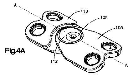
偏心部材112、114の各々は、好ましくは、これらの部材の夫々の上プレート105及び下プレート110に対して回転自在である。図4A及び図5Aでわかるように、偏心部材112、114は元の位置にあるとき、即ち上プレート105のオフセンタ穴106が上プレート105の先端に最も近い位置にあり且つ下プレート110のオフセンタ穴107が下プレート110の先端に最も近い位置にあるとき、スクリュープレート100は、長さ方向軸線A−Aに沿ってその最小長さを持つ。プレート100の長さを延ばすため、オフセンタ偏心部材112、114を個々に回転し、又は協働して回転し、上プレート105及び下プレート110を互いに対して並進できる。
Each of the
図4B及び図5Bでわかるように、下プレート110のオフセンタ偏心部材114を回転し、これによってオフセンタ穴107を下プレート110の先端から更に遠ざかる方向に及び上プレート105の先端に近づく方向に移動すると、下プレート110は上プレート105から遠ざかる方向に並進し、プレート100の長さ方向軸線A−Aに沿った長さを大きくする。同様に、上プレート105のオフセンタ偏心部材112を回転し、これによってオフセンタ穴106を上プレート105の先端から更に遠ざかる方向に及び下プレート110の先端に近づく方向に移動すると、上プレート105は下プレート110から遠ざかる方向に並進し、プレート100の長さ方向軸線A−Aに沿った長さを大きくする。かくして、オフセンタ偏心部材112、114を様々な角度で回転すると、長さ方向軸線A−Aに沿ったプレート100の長さが変化する。図4C及び図5Cでわかるように、下プレート110の偏心部材114を回転し、下プレート110の穴107を下プレート110の先端に対して長さ方向軸線A−Aに沿った最も大きく離れた位置に置き、上プレート105のオフセンタ偏心部材112を回転し、上プレート105の穴106を上プレート105の先端に対して長さ方向軸線A−Aに沿った最も大きく離れた位置に置くと、プレート100は、長さ方向軸線A−Aに沿ってその最大長さをとる。
4B and 5B, when the off-center
同様に、当業者には理解されるように、上プレート105及び下プレート110は、偏心部材112、114のいずれか又は両方を回転することによって、互いに対して及び長さ方向軸線A−Aに対して様々に水平方向に並進できる。その結果、穴106、107はプレート100の水平方向軸線に沿って様々な位置に配置される。水平方向軸線は、長さ方向軸線A−Aに対してほぼ垂直である。
Similarly, as will be appreciated by those skilled in the art, the
従来のプレート固定システムでは、外科医は、代表的には、幾つかの様々な大きさの骨プレートを用いる必要がある。これは、患者の様々な寸法の解剖学的構造を考慮に入れるためである。これとは対照的に、第1の好ましい実施例のプレート100の偏心部材112、114を使用する場合、患者の様々な寸法の解剖学的構造を考慮に入れる上で使用される骨プレートの数が限定される。例えば、以下の計算には、偏心部材112、114を回転することにより、限定された数のプレートで様々な垂直方向距離をカバーできるということが示してある。上プレート105の偏心部材112の偏心性(例えば、mm単位で示す)は、上プレート105の偏心部材112の中心と上プレート105の穴106の中心との間の距離に等しく、下プレート110の偏心部材114の偏心性(例えば、mm単位で示す)は、下プレート110の偏心部材112の中心と下プレート110の穴107の中心との間の距離に等しく、長さ方向軸線A−Aに沿ったプレート100の最大変化は、上プレート105の偏心部材112の偏心性の2倍に下プレート110の偏心部材114の偏心性の2倍を加えた量に等しい((2×112の偏心性)+(2×114の偏心性))。上述のように、長さ方向軸線A−Aに沿ったプレート100の長さは、偏心部材112、114の各々又は両方を回転することによって変化させることができ、様々な解剖学的寸法の患者に対して単一のプレート100を使用できる。
In conventional plate fixation systems, the surgeon typically needs to use several different sized bone plates. This is to take into account the various dimensions of the patient's anatomy. In contrast, when using the
プレート100を埋め込むための一つの例示の手術技術を以下に説明する。しかしながら、プレート100は、本開示を参照することにより当業者に明らかになる多くの技術及び/又は手術工程を使用するということは当業者には理解されよう。
One exemplary surgical technique for implanting the
使用では、中間頚椎又は下頚椎にプレート100を埋め込むため、前外側アプローチが好ましい。プレート100を脊椎の幾つかのセグメントに亘って延長しようとする場合には、長い切開部を形成するのが好ましい。椎骨体を露呈するとき、好ましくは、椎間円板をプレート100によってブリッジしようとする領域だけで前縦靱帯を除去し、又は切開する。このような技術は、隣接したセグメントの前縦靱帯に対する損傷を制限する。
In use, an anterior-lateral approach is preferred because the
切開を行った後、X線透視検査(図示せず)等の蛍光増倍ツールを使用し、好ましくは前側から椎骨に配置したガイドワイヤを案内しモニターする。拡大器を使用し、脊椎の頭端セグメント及び尾端セグメントを拡げ、除去したセグメントの代わりにコルペクトミーインプラント又は天然骨を埋め込む。例えばカリパス器具(図示せず)によってガイドワイヤ間の距離を計測し、この計測値を使用してプレートの大きさを決定できる。距離を決定した後、好ましくは、上プレート105及び下プレート110の偏心部材112、114を回転することによってプレート100を理想的な長さに合わせて調整し、調整したプレート100をガイドワイヤ上に配置する。適正な大きさが決定された後、スクリュー又はファスナを患者に挿入する前又は挿入後にプレート100の係止を行う。これは、中央スクリュー108を締め付けることによって行われる。
After making the incision, a fluorescence intensifying tool such as a fluoroscopy (not shown) is used to guide and monitor a guidewire placed on the vertebra, preferably from the anterior side. Using a dilator, the head and tail segments of the spine are expanded and a colpectomy implant or natural bone is implanted in place of the removed segment. For example, the distance between the guide wires can be measured with a caliper instrument (not shown), and the measured value can be used to determine the size of the plate. After determining the distance, the
プレート100を患者の椎骨に取り付けるため、ガイドワイヤ上でカニュレーテッドスクリューを案内し、ファスナ穴120a、120b、120c、及び120dを通して挿入する。好ましくはカニュレーテッドスクリューを使用するけれども、任意の従来周知の固定手段及び後に開発される固定手段を使用してもよい。例えば、プレート100を椎骨体に固定するため、皮質骨スクリュー、椎弓根スクリュー、又は海綿骨スクリューを椎骨体に配置してもよい。更に、ファスナ又はスクリューの挿入後、係止スクリューを使用してこれらのスクリューを係止できる。係止スクリューの例示の使用は、「骨固定アッセンブリ」という表題の米国特許第6,235,033号に開示されている。出典を明示することにより、この特許に開示された全ての内容は本明細書の開示の一部とされる。
To attach the
図7、図8、及び図9を参照すると、本発明の第2の好ましい実施例による頸椎前方経椎弓根固定システムは、骨ファスナ715の挿入を受け入れる複数の回転自在の偏心圧縮リング706を含む。
Referring to FIGS. 7, 8, and 9, an anterior cervical transpedicular fixation system according to a second preferred embodiment of the present invention includes a plurality of rotatable eccentric compression rings 706 that accept the insertion of
第2の好ましい実施例の固定システムは、二対の固定穴702a、702b、704a、704bを持つプレート700を含む。二対の固定穴702a、702b、704a、704bを持つプレート700が示してあるが、例えばプレート700が更に大きな長さに亘って延びるように、及びかくして脊椎に沿った多くの位置に固定できるように、二対以上の穴が設けられていてもよい。別の態様では、プレート700の各端に、対をなした固定穴702a、702b、704a、704bでなく、単一の穴(図示せず)が設けられていてもよい。
The fixation system of the second preferred embodiment includes a
好ましくは、スロット708及び710がプレート700に形成されている。これらのスロットは、ドリル/ねじガイドを受け入れるため、及びグラフト可視化を行うため、長さ方向中央軸線A−Aに沿って整合している。好ましくは、これらのスロット708、710はファスナ715を受け入れないが、そのような限定はなされない。別の態様では、スロットは一つだけ設けられていてもよいし二つ以上のスロットが設けられていてもよく、スロットは長さ方向中央軸線A−Aに対して横方向に配置されていてもよい。第2の好ましい実施例のスロット708、710は、中央領域の直線状部分及びスロット708、710の端部の半円形部分を含む。
Preferably,
骨ファスナ715の少なくとも一部を受け入れるように形成された固定穴702a、702b、704a、704bの各々は、プレート700の上面と下面との間を延びており、回転自在の偏心圧縮リング706が設けられている。これらの固定穴702a、702b、704a、704bの一つ又は二つだけに回転自在の偏心圧縮リング706が設けられ、他の固定穴702a、702b、704a、704bには圧縮リング706が全く設けられていなくてもよい。例えば、回転自在の偏心圧縮リング706を第3固定穴702b及び第4固定穴704bで使用し、第1固定穴702a及び第2固定穴704aに同心圧縮リング706が収容されていてもよい。別の態様では、六角形や星形等の様々な形状(図示せず)の回転自在の又は固定式の圧縮リング706を使用してもよい。
Each of the
圧縮リング706が偏心しているため、回転自在の偏心圧縮リング706に挿入したねじ715はリング706の中心からずらされている、即ちオフセットしている。このようなオフセット挿入及び回転自在であるという特徴のため、プレート700は、長さ方向軸線A−Aに対して水平方向及び垂直方向の両方向で並進する。この並進は、圧縮リング706を使用することによる骨ねじ715の傾きに加わる。例えば、圧縮リング706が回転自在の偏心性に加え、圧縮リング706は、好ましくは、プレート700に対して最大約20°追加に移動できる。更に、回転自在の偏心圧縮リング706により、ファスナ715の内−外進入点の相違を解消できる。進入点の相違を補正できない場合には、頭端−尾端小距離及び最大距離において、回転自在の偏心圧縮リング706を使用することにより、小さくオフセット配置される。
Since the
更に、圧縮リング706が回転自在の偏心性を備えていることにより並進性が許容され、これにより、大きな解剖学的範囲に対して使用されるプレートの量を最少にできる。例えば、以下の表は、異なる解剖学的距離をカバーする上で、どれ程多くの異なる大きさのデバイスが必要とされるのかを示す。当業者には理解されるように、カバーされる垂直方向最小距離及び最大距離は、偏心圧縮リング706が設けられたファスナ穴の数、プレート700の大きさ、及び偏心圧縮リング706の偏心性で決まる。固定穴の偏心性は、固定穴内の回転自在の偏心圧縮リング706の中心と固定穴の中心との間の距離に等しい。
Further, the
回転自在の偏心圧縮リング706の偏心性が低下すると、又は回転自在の偏心圧縮リング706が設けられたファスナ穴の数が減少すると、関連したプレート700によってカバーできる解剖学的範囲もまた減少する。例えば、以下の表2に示すように、表1について使用されたのと同数のプレートでは、偏心性が減少すると(一つの固定穴の回転自在の偏心圧縮リング706の中心と、このような固定穴の中心との間の距離が小さくなると)プレート700のカバー範囲が小さくなる。かくして、同数のプレートを使用した場合、カバーされる解剖学的範囲が小さい。以下の表は、回転自在の偏心圧縮リング706の偏心性を0.25mm減少した場合、表1におけるのと同じ解剖学的距離をカバーする上で、どれ程多くの異なる大きさのデバイスが必要とされるのかを示す。
As the eccentricity of the rotatable
任意の数の偏心圧縮リング706を備えたプレート700を埋め込むための一つの例示の手術技術を図8A乃至図8Fを参照して説明する。プレート700を中間頚椎又は下頚椎に埋め込むため、前外側アプローチが好ましい。プレート700を幾つかのセグメントに亘って延長する場合、長い切開部が好ましい。椎骨体を露呈するとき、好ましくは、前縦靱帯を、プレート700によって椎間円板がブリッジされるべき箇所のみで、除去するか或いは切開する。この選択的切開により、好ましくは、隣接したセグメントの前縦靱帯の隣接した前セグメントに対する損傷を限定的にする。
One exemplary surgical technique for implanting a
切開部を形成した後、X線透視検査(図示せず)等の蛍光増倍ツールを使用し、好ましくは前側から椎弓根に配置したガイドワイヤ810を案内しモニターする。拡大器を使用し、頭端セグメント及び尾端セグメントを拡げ、除去したセグメントの代わりにコルペクトミーインプラント又は天然骨を埋め込む。例えばカリパス器具(図示せず)によってガイドワイヤ810間の距離を計測し、外科医はこの計測値を使用してプレート700の大きさを決定できる。
After forming the incision, a
次いで、好ましくは、回転自在の偏心圧縮リング706をガイドワイヤ810の周囲に配置し、プレートを骨まで案内し、骨に対して正しく位置決めする。好ましくはカニュレーテッドスクリューであるファスナ715をガイドワイヤ810上で案内し、偏心圧縮リング706に挿入する。図8A乃至図8Dに示すように、第3ファスナ穴702b及び第4ファスナ穴704bだけに偏心圧縮リング706が設けられているが、上文中に論じたように、任意の数のファスナ穴に偏心圧縮リング706が設けられていてもよく、これにより、プレート700の偏心性が変化する。好ましくは、カニュレーテッドスクリュー715が使用されるが、任意の従来周知の、又は後に開発される固定デバイス又は固定手段を使用してもよい。例えば、プレート700を取り付けるため、皮質骨スクリュー、椎弓根スクリュー、又は海綿骨スクリューを椎骨体に配置してもよい。更に、以下に更に詳細説明するように、円錐形係止ねじを使用して皮質骨スクリュー又は海綿骨スクリューを係止してもよい。スクリュー715を挿入した後、好ましくはガイドワイヤ810を除去する。スクリュー715のへッドには、円錐形係止ねじ815を挿入するための凹所812が設けられていてもよい。係止ねじ815は凹所812にねじ込むことができ、これによりスクリュー715をプレート700に対して所定の場所に係止する。偏心圧縮リング706にファスナ715を挿入し、ガイドワイヤ810を除去した後、好ましくは、係止ねじ815をスクリュー715のへッドに挿入し、これによって、挿入したスクリュー715を所定の場所に係止する。
A rotatable
回転自在の偏心圧縮リング706が設けられたファスナ穴にスクリュー715を挿入した後、追加のスクリュー715を残りのファスナ穴に挿入する。回転自在の偏心圧縮リング706が設けられたファスナ穴に挿入したスクリュー715と同様に、残りのファスナ穴に挿入したスクリュー715は、任意の従来周知の、又は後に開発される固定デバイス又は固定手段であってもよい。これには、上文中に論じたように、固定ねじを受け入れることができるへッドを持つスクリューが含まれるが、これに限定されない。
After inserting the
好ましくは、プレート700が対称であるため、患者の脊椎に左側からでも右側からでもアプローチできるということに着目されたい。更に、当業者には理解されるように、プレート700を脊椎の腰椎領域に挿入した場合、前側から配置した複数のスクリュー715と組み合わせることができる。これにより、特定の情況において、後方器具使用に対する必要をなくす。矢状面と人間の脊椎の椎弓根との間の角度が小さいため、ガイドワイヤ810の進入点は、椎骨前側で互いに交差しにくい。
Note that preferably the
図10A、図10B、及び図10Cを参照すると、骨プレート固定システムの第3の好ましい実施例は、回転自在の偏心圧縮リング1012と、骨ファスナ1015、1016を挿入するためのスロット状固定穴1006とを含み、これにより、ファスナ1015、1016、1018a、1018bを骨プレート1000に配置した後、骨折隙間(fracture gap)を追加に圧縮できる。
Referring to FIGS. 10A, 10B, and 10C, a third preferred embodiment of a bone plate fixation system includes a rotatable
第3の好ましい実施例の固定システムは、第1及び第2の固定穴1003、1004a、1004b、及びスロット状固定穴1006が設けられた骨プレート1000を含む。四つの穴1003、1004a、1004b、及び1006を持つプレート1000が示してあるが、プレート1000に設けられた穴の数はこれよりも多くてもよいし少なくてもよく、例えば、プレート1000は、これよりも長い又は短い長さを橋渡ししてもよく、及びかくして骨セグメントに沿った様々な位置及び/又は多数の位置に取り付けられる。骨プレート1000は、好ましくは、各骨片(bone fragments)について少なくとも二つのファスナ1015、1016、1018a、1018bを含む。
The fixation system of the third preferred embodiment includes a
好ましくは、スロット状固定穴1006によりファスナ1016をその場で並進できる。骨ファスナ1016、1015、1018a、1018bの夫々の少なくとも一部を受け入れるように形成された固定穴1006、1003、1004a、1004bの各々は、取り付け位置で、プレート1000の上面と下面との間を延びる。第1固定穴1003は、好ましくは、回転自在の偏心圧縮リング1012を含む。固定穴1006、1003、1004a、1004bの多くに回転自在の偏心圧縮リング1012が設けられていてもよいが、これらの固定穴1006、1003、1004a、1004bのうちの他の穴には、同心圧縮リング1012が設けられていてもよいし、圧縮リングが全く設けられていなくてもよい。別の態様では、回転自在の又は固定式の圧縮リング1012は、六角形や星形等の様々な形状を使用してもよい。
Preferably, the
圧縮リング1012が偏心しているため、スクリュー1015は、圧縮リング1012等の中心からオフセットしている。プレート1000は、オフセット挿入及び回転自在の特徴により、その長さ方向軸線に対して水平方向及び/又は垂直方向に移動する。この並進は、骨ねじ1015を傾けることに加えて行われる。これは、圧縮リング1012を使用することによる。例えば、圧縮リング1012が回転自在であること及び偏心していることにより並進が可能になることに加え、圧縮リング1012により、プレート1000に対して追加に最大約20°移動できる。更に、図10A、図10B、及び図10Cでわかるように、ファスナ1015は円錐形ねじへッドを備えていてもよく、これにより、固定穴1003に挿入したとき、圧縮リング1012を拡げることができ、これによりファスナ1015を所定の場所に係止する。
Since the
プレート1000を骨折場所に埋め込んで骨片間の隙間を橋渡しする場合には、ファスナ穴1004a、1004bを隙間の一方の側に配置し、ファスナ穴1006、1003を隙間又は異常がある椎間板隙の他方の側に配置し、ファスナ1016、1018a、1018bを使用して骨に固定する。ファスナ1015を固定穴1003に部分的に挿入した後、外科医の判断で圧縮リング1012を最大180°回転できる。これにより、外科医は、骨片の整合に悪影響を及ぼすことなく、補正作用として骨折隙間を圧縮できる。ファスナ1015についての適正な位置を選択し、圧縮リング1012を適切に回転した後、ファスナ1015を埋め込む。
When the
本発明の方法及びシステムには多くの用途があり、多くの方法で実施でき、上掲の実施例及び例に限定されないということは当業者には理解されよう。本明細書中に説明した様々な実施例の特徴のうちの任意の特徴を一つの実施例に組み込んでもよく、本明細書中に説明した特徴の全て又はこれらの特徴のうちの幾つかを含む変形例も可能である。更に、機能性を、現在周知の又はこれから知られる方法で、多くの構成要素に、全体として又は部分的に分配してもよい。更に、本発明の範囲は、当業者には理解されるように、本明細書中に説明した構成要素の特徴の変形及び変更を含む。従って、本明細書に添付した特許請求の範囲の範囲のみによって限定しようとするものである。 Those skilled in the art will appreciate that the methods and systems of the present invention have many applications, can be implemented in many ways, and are not limited to the above-described embodiments and examples. Any of the features of the various embodiments described herein may be incorporated into a single embodiment, including all of the features described herein or some of these features. Variations are possible. Furthermore, the functionality may be distributed, in whole or in part, to a number of components in a manner now well known or known. Further, the scope of the invention includes variations and modifications of the features of the components described herein, as will be appreciated by those skilled in the art. Accordingly, it is intended that the invention be limited only by the scope of the claims appended hereto.
更に、特許請求の範囲は、本明細書中に説明した本発明の包括的特徴及び特定的特徴の全て、及びこれらの特徴の間に存すると言うことができる本発明の範囲についての全ての言及を含もうとするものであるということは理解されるべきである。 Further, the claims are intended to cover all of the generic and specific features of the invention described herein, and all references to the scope of the invention that may be said to be between those features. It should be understood that it is intended to contain.
上文中に説明した実施例に対し、本発明の広い外面から逸脱することなく、変更を行うことができるということは当業者には理解されよう。従って、本発明は、開示の特定の実施例に限定されず、添付の特許請求の範囲に定義された本発明の精神及び範囲内の変更を含もうとするものであるということは理解されよう。 Those skilled in the art will appreciate that changes can be made to the embodiments described above without departing from the broad exterior aspects of the invention. Accordingly, it is to be understood that the invention is not limited to the specific embodiments disclosed, but is intended to include modifications within the spirit and scope of the invention as defined in the appended claims. .
100 係止プレート
105 上プレート
106 オフセンタ穴
107 オフセンタ穴
108 中央スクリュー
110 下プレート
112 リング状偏心部材
114 リング状偏心部材
120a、120b、120c、120d ファスナ穴
715 骨ファスナ
100
Claims (10)
上面及び下面と、第1骨ファスナの少なくとも一部を受け入れるように形成された、前記上面から前記下面まで貫通した少なくとも一つのファスナ穴と、中央ファスナの少なくとも一部を受け入れるための第1穴を持つ回転自在の第1偏心部材とを持つ第1プレートと、
上面及び下面と、第2骨ファスナの少なくとも一部を受け入れるように形成された、前記上面から前記下面まで貫通した少なくとも一つのファスナ穴と、前記中央ファスナの少なくとも一部を受け入れるための第2穴を持つ回転自在の第2偏心部材とを持つ第2プレートとを含み、
前記第1及び第2の回転自在の偏心部材により、前記第1プレート及び前記第2プレートを互いに関して垂直方向に並進でき、前記中央ファスナを前記第1及び第2の穴を通して前進することにより、前記第2プレートに関する前記第1プレートの配向を固定できる、骨固定デバイス。 In a bone fixation device with a central longitudinal axis,
Upper and lower surfaces, at least one fastener hole extending from the upper surface to the lower surface, configured to receive at least a portion of the first bone fastener, and a first hole for receiving at least a portion of the central fastener. A first plate having a rotatable first eccentric member;
Upper and lower surfaces, at least one fastener hole extending from the upper surface to the lower surface, configured to receive at least a portion of a second bone fastener, and a second hole for receiving at least a portion of the central fastener A second plate having a rotatable second eccentric member having
By the first and second rotatable eccentric members, the first plate and the second plate can be translated vertically relative to each other, and the central fastener is advanced through the first and second holes; A bone fixation device capable of fixing the orientation of the first plate relative to the second plate.
前記第1及び第2の回転自在の偏心部材により、更に、前記第1プレート及び前記第2プレートを互いに関して水平方向に並進できる、骨固定デバイス。 The bone fixation device of claim 1, wherein
A bone fixation device wherein the first and second rotatable eccentric members can further translate the first plate and the second plate in a horizontal direction relative to each other.
前記骨固定アッセンブリは、前記第1穴が、前記長さ方向中央軸線に沿って、前記上プレートの少なくとも一つのファスナ穴からその最も遠い位置にあり、前記第2穴が、前記長さ方向中央軸線に沿って、前記下プレートの少なくとも一つのファスナ穴からその最も遠い位置にあるとき、前記長さ方向中央軸線に沿ってその最大長さをとる、骨固定デバイス。 The bone fixation device of claim 1, wherein
In the bone anchoring assembly, the first hole is located farthest from at least one fastener hole of the upper plate along the longitudinal central axis, and the second hole is the longitudinal center. A bone fixation device that takes its maximum length along the longitudinal central axis when it is farthest from at least one fastener hole in the lower plate along an axis.
前記骨固定アッセンブリは、前記第1穴が、前記長さ方向中央軸線に沿って、前記上プレートの少なくとも一つのファスナ穴に対してその最も近い位置にあり、前記第2穴が、前記長さ方向中央軸線に沿って、前記下プレートの少なくとも一つのファスナ穴に対してその最も近い位置にあるとき、前記長さ方向中央軸線に沿ってその最小長さをとる、骨固定デバイス。 The bone fixation device of claim 1, wherein
In the bone anchoring assembly, the first hole is located closest to the at least one fastener hole of the upper plate along the longitudinal central axis, and the second hole is the length. A bone fixation device that takes its minimum length along the longitudinal central axis when it is closest to at least one fastener hole in the lower plate along the longitudinal central axis.
前記上プレートの前記下面の少なくとも一部及び前記下プレートの前記上面の少なくとも一部は、前記第1及び第2の穴を通して前記中央ファスナを挿入したとき、これらの部分の間の摩擦を可能にする所定の粗さを有する、骨固定デバイス。 The bone fixation device of claim 1, wherein
At least a portion of the lower surface of the upper plate and at least a portion of the upper surface of the lower plate allow friction between these portions when the central fastener is inserted through the first and second holes. A bone fixation device having a predetermined roughness.
上面、下面、及び前記上面と前記下面との間を延びる少なくとも一つの固定穴を含む、長さ方向中央軸線を持つプレートと、
前記少なくとも一つの固定穴の少なくとも一部に配置された少なくとも一つの回転自在の偏心圧縮リングと、
へッド及びねじシャフトを備えた少なくとも一つのファスナとを含み、
前記少なくとも一つの回転自在の偏心圧縮リングは、前記プレートを前記少なくとも一つのファスナに対して並進できるように形成されており且つそのような寸法を備えている、骨固定システム。 In bone fixation system,
A plate having a central longitudinal axis including an upper surface, a lower surface, and at least one fixing hole extending between the upper surface and the lower surface;
At least one rotatable eccentric compression ring disposed in at least a portion of the at least one fixing hole;
At least one fastener with a head and a threaded shaft;
The bone fixation system, wherein the at least one rotatable eccentric compression ring is configured to translate the plate relative to the at least one fastener and has such dimensions.
前記プレートの前記長さ方向中央軸線を通って延びるスロットを含む、骨固定システム。 The bone fixation system of claim 6, further comprising:
A bone fixation system including a slot extending through the longitudinal central axis of the plate.
前記プレートは複数の固定穴を含み、これらの複数の固定穴のうちの少なくとも一つの穴に同心圧縮リングが配置されている、骨固定システム。 The bone fixation system according to claim 6,
The bone fixation system, wherein the plate includes a plurality of fixation holes, and a concentric compression ring is disposed in at least one of the plurality of fixation holes.
前記少なくとも一つのファスナは、ねじシャフト及びへッドを含み、前記へッドは、ねじ山を備えた係止ねじを挿入するための凹所を形成する半径方向壁及び開放端を含み、前記ねじ山を備えた係止ねじを前記ファスナの前記へッドにねじ込んだとき、前記半径方向壁が外方に拡張し、前記偏心圧縮リングの壁と相互作用する、骨固定システム。 The bone fixation system according to claim 6,
The at least one fastener includes a screw shaft and a head, the head including a radial wall and an open end forming a recess for inserting a threaded locking screw; A bone fixation system wherein the radial wall expands outward and interacts with the wall of the eccentric compression ring when a locking screw with a thread is screwed into the head of the fastener.
第1骨ファスナの少なくとも一部を受け入れるように形成された少なくとも一つのファスナ穴と、中央ファスナの少なくとも一部を受け入れるための第1穴を持つ回転自在の第1偏心部材とを含む第1プレートと、
第2骨ファスナの少なくとも一部を受け入れるように形成された少なくとも一つのファスナ穴と、中央ファスナの少なくとも一部を受け入れるための第2穴を持つ回転自在の第1偏心部材とを含む第2プレートとを含む、
固定アッセンブリを提供する工程と、
骨ファスナで前記アッセンブリを前記複数の骨セグメントに取り付けるための最適の位置を決定するため、多数のガイドワイヤを挿入する工程と、
挿入したガイドワイヤ間の距離を計測する工程と、
前記第1プレートの前記ファスナ穴と前記第2プレートの前記ファスナ穴との間の距離が、前記ガイドワイヤ間の計測された距離と等しいように前記固定アッセンブリの大きさを定めるため、第1及び第2の偏心部材を回転する工程と、
前記第1及び第2の穴に前記中央ファスナを挿入する工程と、
前記第1プレートを第1骨セグメントに少なくとも一つの骨ファスナによって取り付け、前記第2プレートを第2骨セグメントに少なくとも一つの骨ファスナによって取り付ける工程とを含む、方法。 In a method for securing a plurality of bone segments,
A first plate including at least one fastener hole configured to receive at least a portion of the first bone fastener and a rotatable first eccentric member having a first hole for receiving at least a portion of the central fastener. When,
A second plate including at least one fastener hole configured to receive at least a portion of the second bone fastener and a rotatable first eccentric member having a second hole for receiving at least a portion of the central fastener. Including
Providing a stationary assembly; and
Inserting a number of guide wires to determine an optimal position for attaching the assembly to the plurality of bone segments with a bone fastener;
Measuring the distance between the inserted guide wires;
In order to size the fixing assembly such that the distance between the fastener hole in the first plate and the fastener hole in the second plate is equal to the measured distance between the guide wires, Rotating the second eccentric member;
Inserting the central fastener into the first and second holes;
Attaching the first plate to the first bone segment with at least one bone fastener and attaching the second plate to the second bone segment with at least one bone fastener.
Applications Claiming Priority (3)
| Application Number | Priority Date | Filing Date | Title |
|---|---|---|---|
| US9803608P | 2008-09-18 | 2008-09-18 | |
| US61/098,036 | 2008-09-18 | ||
| PCT/US2009/057454 WO2010033786A2 (en) | 2008-09-18 | 2009-09-18 | Anterior transpedicular screw-and-plate system |
Publications (2)
| Publication Number | Publication Date |
|---|---|
| JP2012502760A true JP2012502760A (en) | 2012-02-02 |
| JP2012502760A5 JP2012502760A5 (en) | 2012-11-01 |
Family
ID=41528794
Family Applications (1)
| Application Number | Title | Priority Date | Filing Date |
|---|---|---|---|
| JP2011527989A Ceased JP2012502760A (en) | 2008-09-18 | 2009-09-18 | Anterior transpedicular screw-plate system |
Country Status (9)
| Country | Link |
|---|---|
| US (1) | US20120022600A1 (en) |
| EP (2) | EP2368506A1 (en) |
| JP (1) | JP2012502760A (en) |
| KR (1) | KR20110069073A (en) |
| CN (1) | CN102159149A (en) |
| AT (1) | ATE541525T1 (en) |
| BR (1) | BRPI0918606A2 (en) |
| CA (1) | CA2735683A1 (en) |
| WO (1) | WO2010033786A2 (en) |
Cited By (9)
| Publication number | Priority date | Publication date | Assignee | Title |
|---|---|---|---|---|
| KR101331428B1 (en) * | 2012-08-03 | 2013-11-21 | 주식회사 솔고 바이오메디칼 | Apparatus for fixing a cervical spine following an inserting angle of screw |
| JP2016073629A (en) * | 2014-10-03 | 2016-05-12 | ストライカー・ユーロピアン・ホールディングス・I,リミテッド・ライアビリティ・カンパニー | Artificial joint extension plate |
| JP2017127615A (en) * | 2015-12-29 | 2017-07-27 | オーソヒーリクス・サージカル・デザインズ・インコーポレイテッドOrthohelix Surgical Designs, Inc. | Bone plate, bone staple, bone plate assembly and orthopedic plate system |
| JP2017196469A (en) * | 2012-05-10 | 2017-11-02 | スパイナル シンプリシティ エルエルシーSpinal Simplicity LLC | Dynamic fracture plate |
| US10092336B2 (en) | 2012-05-10 | 2018-10-09 | Spinal Simplicity, Llc | Dynamic bone fracture plates |
| JP2019037782A (en) * | 2017-08-24 | 2019-03-14 | ジンマー ゲーエムベーハー | Orthopedic plates, orthopedic devices, methods of joining bone segments, and methods of assembling orthopedic plates. |
| US10485592B2 (en) | 2012-05-10 | 2019-11-26 | Spinal Simplicity, Llc | Locking fastener for use with dynamic bone fracture plates |
| WO2019240103A1 (en) * | 2018-06-12 | 2019-12-19 | オリンパステルモバイオマテリアル株式会社 | Bone surgery instrument |
| US11517359B2 (en) | 2018-06-12 | 2022-12-06 | Olympus Terumo Biomaterials Corp. | Bone plate and bone plate kit |
Families Citing this family (34)
| Publication number | Priority date | Publication date | Assignee | Title |
|---|---|---|---|---|
| US9039768B2 (en) | 2006-12-22 | 2015-05-26 | Medos International Sarl | Composite vertebral spacers and instrument |
| US20090248092A1 (en) | 2008-03-26 | 2009-10-01 | Jonathan Bellas | Posterior Intervertebral Disc Inserter and Expansion Techniques |
| US9526620B2 (en) | 2009-03-30 | 2016-12-27 | DePuy Synthes Products, Inc. | Zero profile spinal fusion cage |
| US9393129B2 (en) | 2009-12-10 | 2016-07-19 | DePuy Synthes Products, Inc. | Bellows-like expandable interbody fusion cage |
| US11529241B2 (en) | 2010-09-23 | 2022-12-20 | DePuy Synthes Products, Inc. | Fusion cage with in-line single piece fixation |
| US20120078372A1 (en) | 2010-09-23 | 2012-03-29 | Thomas Gamache | Novel implant inserter having a laterally-extending dovetail engagement feature |
| US20120078373A1 (en) | 2010-09-23 | 2012-03-29 | Thomas Gamache | Stand alone intervertebral fusion device |
| EP2910208B1 (en) | 2011-04-01 | 2017-05-17 | Synthes GmbH | Posterior vertebral plating system |
| US11123117B1 (en) | 2011-11-01 | 2021-09-21 | Nuvasive, Inc. | Surgical fixation system and related methods |
| CA2857992C (en) * | 2011-12-09 | 2018-08-14 | Zimmer Gmbh | Orthopedic plate, orthopedic device, method of coupling bone segments, and method of assembling an orthopedic plate |
| EP2623058A3 (en) * | 2012-02-06 | 2013-09-11 | Crcaholic S.A. | Fixing device and tool for surgical holding systems |
| US9271836B2 (en) | 2012-03-06 | 2016-03-01 | DePuy Synthes Products, Inc. | Nubbed plate |
| US10182921B2 (en) | 2012-11-09 | 2019-01-22 | DePuy Synthes Products, Inc. | Interbody device with opening to allow packing graft and other biologics |
| AU2014365821B2 (en) | 2013-12-20 | 2019-10-03 | Crossroads Extremity Systems, Llc | Polyaxial locking hole |
| PT3164093T (en) * | 2014-07-03 | 2024-04-04 | Acumed Llc | Bone plate with movable joint |
| US11202626B2 (en) | 2014-07-10 | 2021-12-21 | Crossroads Extremity Systems, Llc | Bone implant with means for multi directional force and means of insertion |
| EP3653152B1 (en) | 2014-07-10 | 2024-05-01 | Crossroads Extremity Systems, LLC | Bone implant and means of insertion |
| USD779065S1 (en) | 2014-10-08 | 2017-02-14 | Nuvasive, Inc. | Anterior cervical bone plate |
| CN110151291B (en) * | 2015-07-13 | 2020-12-22 | 汇聚义肢系统有限责任公司 | Bone plate with dynamic element |
| WO2017035031A1 (en) * | 2015-08-21 | 2017-03-02 | Scott Meyer | Pedicle screw placement system and method for spinal surgery |
| EP3320867B1 (en) | 2016-11-14 | 2021-08-04 | Biedermann Technologies GmbH & Co. KG | Modular bone plate and member of such a modular bone plate |
| US11864753B2 (en) | 2017-02-06 | 2024-01-09 | Crossroads Extremity Systems, Llc | Implant inserter |
| EP3579762B1 (en) | 2017-02-07 | 2024-06-26 | Crossroads Extremity Systems, LLC | Counter-torque implant |
| US10940016B2 (en) | 2017-07-05 | 2021-03-09 | Medos International Sarl | Expandable intervertebral fusion cage |
| CN107753095A (en) * | 2017-11-17 | 2018-03-06 | 常州集硕医疗器械有限公司 | One kind can be with rod convolution spine board |
| WO2020158998A1 (en) * | 2019-01-29 | 2020-08-06 | 고려대학교 산학협력단 | Fixing unit for fracture treatment, and traction unit and bone screw for fracture treatment used for fixing unit |
| CN109965967B (en) * | 2019-05-08 | 2022-05-06 | 天津市康尔医疗器械有限公司 | Craniomaxillofacial bone fracture plate |
| US11389209B2 (en) | 2019-07-19 | 2022-07-19 | Medos International Sarl | Surgical plating systems, devices, and related methods |
| US12059183B2 (en) | 2020-07-31 | 2024-08-13 | Crossroads Extremity Systems, Llc | Bone plates with dynamic elements and screws |
| US11974785B2 (en) * | 2020-10-16 | 2024-05-07 | Globus Medical, Inc | Band clamp implants |
| USD961081S1 (en) | 2020-11-18 | 2022-08-16 | Crossroads Extremity Systems, Llc | Orthopedic implant |
| PL244434B1 (en) * | 2021-08-09 | 2024-01-29 | Univ Zielonogorski | A set of elements for osteotomy, with the possibility of connecting with each other and expanding |
| PL244435B1 (en) * | 2021-08-09 | 2024-01-29 | Univ Zielonogorski | A set of elements for osteotomy, with the possibility of connecting with each other and expanding |
| KR102596974B1 (en) * | 2023-05-23 | 2023-11-02 | (주)서지오젠 | Cervical plate for easy reoperation |
Citations (3)
| Publication number | Priority date | Publication date | Assignee | Title |
|---|---|---|---|---|
| US20070123869A1 (en) * | 2003-09-24 | 2007-05-31 | Spinefrontier Lls | Apparatus and method for spine fixation |
| JP2010510852A (en) * | 2006-11-29 | 2010-04-08 | サージクラフト リミテッド | Orthopedic implants and prostheses |
| JP2010516413A (en) * | 2007-01-30 | 2010-05-20 | ウルリッヒ ゲーエムベーハー ウント コンパニ カーゲー | Plate implants, especially for use in the spinal column |
Family Cites Families (19)
| Publication number | Priority date | Publication date | Assignee | Title |
|---|---|---|---|---|
| US1811363A (en) * | 1929-05-22 | 1931-06-23 | Henry E Morton | Milling machine |
| US2096116A (en) * | 1934-02-16 | 1937-10-19 | Leighton John Wycliffe | Independent wheel suspension |
| US1987661A (en) * | 1934-04-06 | 1935-01-15 | Frederick J Blauvelt | Variable connection between crank and piston |
| CH645264A5 (en) * | 1980-05-28 | 1984-09-28 | Straumann Inst Ag | FITTING WITH A PLATE AND SCREWS THAT FIX IT TO A BONE. |
| US6206397B1 (en) * | 1995-01-25 | 2001-03-27 | James B. Klassen | Bicycle wheel travel path for selectively applying chainstay lengthening effect and apparatus for providing same |
| DE19545612C2 (en) * | 1995-12-07 | 2001-08-30 | Aesculap Ag & Co Kg | Orthopedic retention system |
| ATE241093T1 (en) * | 1999-03-24 | 2003-06-15 | Fev Motorentech Gmbh | COUPLING ELEMENT FOR CONNECTING TWO AXIS-PARALLEL SHAFTS ARRANGED ON THE SAME AXIS, BEHIND EACH OTHER AND AT A TRANSVERSAL DISTANCE FROM EACH OTHER |
| US6235033B1 (en) | 2000-04-19 | 2001-05-22 | Synthes (Usa) | Bone fixation assembly |
| US6641583B2 (en) * | 2001-03-29 | 2003-11-04 | Endius Incorporated | Apparatus for retaining bone portions in a desired spatial relationship |
| US7090676B2 (en) * | 2002-11-19 | 2006-08-15 | Acumed Llc | Adjustable bone plates |
| US7041105B2 (en) * | 2001-06-06 | 2006-05-09 | Sdgi Holdings, Inc. | Dynamic, modular, multilock anterior cervical plate system having detachably fastened assembleable and moveable segments |
| US7303564B2 (en) * | 2002-02-01 | 2007-12-04 | Spinal Concepts, Inc. | Spinal plate extender system and method |
| US6695846B2 (en) * | 2002-03-12 | 2004-02-24 | Spinal Innovations, Llc | Bone plate and screw retaining mechanism |
| US20050049595A1 (en) * | 2003-09-03 | 2005-03-03 | Suh Sean S. | Track-plate carriage system |
| US7488327B2 (en) * | 2004-04-12 | 2009-02-10 | Synthes (U.S.A.) | Free hand drill guide |
| US8025681B2 (en) * | 2006-03-29 | 2011-09-27 | Theken Spine, Llc | Dynamic motion spinal stabilization system |
| US8257355B2 (en) * | 2006-06-07 | 2012-09-04 | Spinefrontier Inc. | Methods and devices for static or dynamic spine stabilization |
| US20080039847A1 (en) * | 2006-08-09 | 2008-02-14 | Mark Piper | Implant and system for stabilization of the spine |
| US8287574B2 (en) * | 2008-08-06 | 2012-10-16 | The University Of Toledo | Cervical plate assembly |
-
2009
- 2009-09-18 CN CN200980136491XA patent/CN102159149A/en active Pending
- 2009-09-18 JP JP2011527989A patent/JP2012502760A/en not_active Ceased
- 2009-09-18 BR BRPI0918606A patent/BRPI0918606A2/en not_active IP Right Cessation
- 2009-09-18 EP EP11004993A patent/EP2368506A1/en not_active Withdrawn
- 2009-09-18 EP EP09792704A patent/EP2323573B1/en not_active Not-in-force
- 2009-09-18 AT AT09792704T patent/ATE541525T1/en active
- 2009-09-18 CA CA2735683A patent/CA2735683A1/en not_active Abandoned
- 2009-09-18 KR KR1020117008417A patent/KR20110069073A/en not_active Withdrawn
- 2009-09-18 US US13/119,830 patent/US20120022600A1/en not_active Abandoned
- 2009-09-18 WO PCT/US2009/057454 patent/WO2010033786A2/en not_active Ceased
Patent Citations (3)
| Publication number | Priority date | Publication date | Assignee | Title |
|---|---|---|---|---|
| US20070123869A1 (en) * | 2003-09-24 | 2007-05-31 | Spinefrontier Lls | Apparatus and method for spine fixation |
| JP2010510852A (en) * | 2006-11-29 | 2010-04-08 | サージクラフト リミテッド | Orthopedic implants and prostheses |
| JP2010516413A (en) * | 2007-01-30 | 2010-05-20 | ウルリッヒ ゲーエムベーハー ウント コンパニ カーゲー | Plate implants, especially for use in the spinal column |
Cited By (10)
| Publication number | Priority date | Publication date | Assignee | Title |
|---|---|---|---|---|
| JP2017196469A (en) * | 2012-05-10 | 2017-11-02 | スパイナル シンプリシティ エルエルシーSpinal Simplicity LLC | Dynamic fracture plate |
| US10092336B2 (en) | 2012-05-10 | 2018-10-09 | Spinal Simplicity, Llc | Dynamic bone fracture plates |
| US10485592B2 (en) | 2012-05-10 | 2019-11-26 | Spinal Simplicity, Llc | Locking fastener for use with dynamic bone fracture plates |
| KR101331428B1 (en) * | 2012-08-03 | 2013-11-21 | 주식회사 솔고 바이오메디칼 | Apparatus for fixing a cervical spine following an inserting angle of screw |
| JP2016073629A (en) * | 2014-10-03 | 2016-05-12 | ストライカー・ユーロピアン・ホールディングス・I,リミテッド・ライアビリティ・カンパニー | Artificial joint extension plate |
| JP2017127615A (en) * | 2015-12-29 | 2017-07-27 | オーソヒーリクス・サージカル・デザインズ・インコーポレイテッドOrthohelix Surgical Designs, Inc. | Bone plate, bone staple, bone plate assembly and orthopedic plate system |
| JP2019037782A (en) * | 2017-08-24 | 2019-03-14 | ジンマー ゲーエムベーハー | Orthopedic plates, orthopedic devices, methods of joining bone segments, and methods of assembling orthopedic plates. |
| WO2019240103A1 (en) * | 2018-06-12 | 2019-12-19 | オリンパステルモバイオマテリアル株式会社 | Bone surgery instrument |
| JPWO2019240103A1 (en) * | 2018-06-12 | 2021-06-17 | オリンパステルモバイオマテリアル株式会社 | Bone surgical instruments |
| US11517359B2 (en) | 2018-06-12 | 2022-12-06 | Olympus Terumo Biomaterials Corp. | Bone plate and bone plate kit |
Also Published As
| Publication number | Publication date |
|---|---|
| EP2323573A2 (en) | 2011-05-25 |
| BRPI0918606A2 (en) | 2018-10-09 |
| WO2010033786A3 (en) | 2010-06-24 |
| KR20110069073A (en) | 2011-06-22 |
| EP2368506A1 (en) | 2011-09-28 |
| US20120022600A1 (en) | 2012-01-26 |
| WO2010033786A2 (en) | 2010-03-25 |
| EP2323573B1 (en) | 2012-01-18 |
| ATE541525T1 (en) | 2012-02-15 |
| CA2735683A1 (en) | 2010-03-25 |
| CN102159149A (en) | 2011-08-17 |
Similar Documents
| Publication | Publication Date | Title |
|---|---|---|
| JP2012502760A (en) | Anterior transpedicular screw-plate system | |
| US8092494B2 (en) | Pedicle screw constructs for spine fixation systems | |
| US11026802B2 (en) | Bone plate stabilization system and method for its use | |
| JP4564487B2 (en) | Non-metallic orthopedic plate | |
| AU2015259466B2 (en) | Sacral fixation system | |
| AU2017216441B2 (en) | Bone plate assemblies with mesh portions | |
| KR20070056033A (en) | Variable Jumbo Plastic Surgery Implant | |
| JP5649666B2 (en) | Odontoid fracture dynamic compression device | |
| US20090240291A1 (en) | Breached pedicle screw | |
| US10390861B2 (en) | Spinal stabilization device, system, and method of use | |
| US20110245880A1 (en) | Spinal fixator and method of use thereof | |
| US12144742B2 (en) | Implant system and methods of use | |
| US9060813B1 (en) | Surgical fixation system and related methods | |
| US20240164909A1 (en) | Implant system and methods of use | |
| KR20220159743A (en) | Spine surgery instrument | |
| EP1703849A2 (en) | Pedicle screw constructs for spine fixation systems |
Legal Events
| Date | Code | Title | Description |
|---|---|---|---|
| A521 | Request for written amendment filed |
Free format text: JAPANESE INTERMEDIATE CODE: A523 Effective date: 20120913 |
|
| A621 | Written request for application examination |
Free format text: JAPANESE INTERMEDIATE CODE: A621 Effective date: 20120913 |
|
| A01 | Written decision to grant a patent or to grant a registration (utility model) |
Free format text: JAPANESE INTERMEDIATE CODE: A01 Effective date: 20131028 |
|
| A045 | Written measure of dismissal of application [lapsed due to lack of payment] |
Free format text: JAPANESE INTERMEDIATE CODE: A045 Effective date: 20140224 |