EP1978394A1 - Optical system for increasing depth of field - Google Patents
Optical system for increasing depth of field Download PDFInfo
- Publication number
- EP1978394A1 EP1978394A1 EP07300936A EP07300936A EP1978394A1 EP 1978394 A1 EP1978394 A1 EP 1978394A1 EP 07300936 A EP07300936 A EP 07300936A EP 07300936 A EP07300936 A EP 07300936A EP 1978394 A1 EP1978394 A1 EP 1978394A1
- Authority
- EP
- European Patent Office
- Prior art keywords
- optical system
- image
- field
- nanometers
- distance
- Prior art date
- Legal status (The legal status is an assumption and is not a legal conclusion. Google has not performed a legal analysis and makes no representation as to the accuracy of the status listed.)
- Withdrawn
Links
Images


Classifications
-
- G—PHYSICS
- G02—OPTICS
- G02B—OPTICAL ELEMENTS, SYSTEMS OR APPARATUS
- G02B27/00—Optical systems or apparatus not provided for by any of the groups G02B1/00 - G02B26/00, G02B30/00
- G02B27/0075—Optical systems or apparatus not provided for by any of the groups G02B1/00 - G02B26/00, G02B30/00 with means for altering, e.g. increasing, the depth of field or depth of focus
-
- A—HUMAN NECESSITIES
- A61—MEDICAL OR VETERINARY SCIENCE; HYGIENE
- A61B—DIAGNOSIS; SURGERY; IDENTIFICATION
- A61B3/00—Apparatus for testing the eyes; Instruments for examining the eyes
- A61B3/10—Objective types, i.e. instruments for examining the eyes independent of the patients' perceptions or reactions
- A61B3/14—Arrangements specially adapted for eye photography
-
- A—HUMAN NECESSITIES
- A61—MEDICAL OR VETERINARY SCIENCE; HYGIENE
- A61B—DIAGNOSIS; SURGERY; IDENTIFICATION
- A61B5/00—Measuring for diagnostic purposes; Identification of persons
- A61B5/117—Identification of persons
- A61B5/1171—Identification of persons based on the shapes or appearances of their bodies or parts thereof
-
- G—PHYSICS
- G02—OPTICS
- G02B—OPTICAL ELEMENTS, SYSTEMS OR APPARATUS
- G02B13/00—Optical objectives specially designed for the purposes specified below
- G02B13/20—Soft-focus objectives
-
- G—PHYSICS
- G02—OPTICS
- G02B—OPTICAL ELEMENTS, SYSTEMS OR APPARATUS
- G02B27/00—Optical systems or apparatus not provided for by any of the groups G02B1/00 - G02B26/00, G02B30/00
- G02B27/0025—Optical systems or apparatus not provided for by any of the groups G02B1/00 - G02B26/00, G02B30/00 for optical correction, e.g. distorsion, aberration
-
- G—PHYSICS
- G06—COMPUTING OR CALCULATING; COUNTING
- G06V—IMAGE OR VIDEO RECOGNITION OR UNDERSTANDING
- G06V40/00—Recognition of biometric, human-related or animal-related patterns in image or video data
- G06V40/10—Human or animal bodies, e.g. vehicle occupants or pedestrians; Body parts, e.g. hands
- G06V40/18—Eye characteristics, e.g. of the iris
- G06V40/19—Sensors therefor
Definitions
- the present invention relates generally to optical systems for use with imaging systems, including digital image and digital video capture systems amongst others.
- the goal for a wide range of requirements and applications is to minimize aberrations induced by the lens. Aberrations are considered to reduce resolution and contrast. Lens designers seek to avoid aberrations, especially in high quality imaging applications.
- aberrations arise from two origins: optical design and manufacturing errors that should stay in an allowed range of tolerances.
- Aberrations of a lens can be separated into different kinds, such as Zemike has done, where each aberration has specific effects on an image while commonly adversely affecting resolution and contrast of the image.
- an optical system comprising at least one optical element adapted to provide a spherical aberration in the range of about 0.2 wave to about 5 wave for increasing the depth of field of the optical system.
- the optical element may comprise at least one lens.
- the increased depth of field may be in the light wavelength range of about 300 nanometers to about 1200 nanometers. Alternatively, the increased depth of field may be in the light wavelength range of about 700 nanometers to about 900 nanometers.
- the optical system may further comprise a system for digitally processing images to increase their Modulation Transfer Function (MTF) at spatial frequencies below the Nyquist Limit.
- MTF Modulation Transfer Function
- an optical system for producing an image of an object.
- the optical system comprises at least one of a lens and an optical element adapted to provide a chromatic aberration in the range of about 0.2 wave to 0.9 wave for increasing the depth of field of the system.
- the optical system may comprise a plurality of lenses. Further, the optical system may comprise a plurality of optical elements.
- the increased depth of field may be in the light wavelength range of about 300 nanometers to about 1200 nanometers.
- the optical system may further comprise a system for digitally processing images to increase their Modulation Transfer Function (MTF) at spatial frequencies below the Nyquist Limit.
- MTF Modulation Transfer Function
- the increased depth of field may be in the light wavelength range of about 700 nanometers to about 900 nanometers. Images produced by the optical system may be digitally processed to increase their Modulation Transfer Function at spatial frequencies below the Nyquist Limit.
- the spherical aberration may range from about 0.2 wave to about 0.9 wave and provide an increased depth of field and reduced Modulation Transfer Function at spatial frequencies below the Nyquist Limit, the increased depth of field and the reduced Modulation Transfer Function being further increased by digital image processing applied to an image obtained using the optical system.
- the spherical aberration may range from about 0.2 wave to about 5 wave providing the increased depth of field, an image produced using the optical system having a reduced Modulation Transfer Function at spatial frequencies below the Nyquist Limit.
- the optical system may further comprise a module for digital image processing of an image obtained using the system dependent upon a distance determined between an object and the optical system to increase the Modulation Transfer Function at spatial frequencies below the Nyquist Limit.
- the optical system may further comprise a device for determining the distance between the object and the optical system. Alternatively, a characteristic of an image may used to determine the distance between the object and the optical system.
- a local Edge Spread Function may be used from a known object in the image to extract the distance between the object and the optical system.
- an optical system comprising at least one optical element adapted to having an axial chromatic aberration of about 0.4 to about 20 times the Fresnel distance in image space for increasing the depth of field while reducing the magnitude of non-central rings in a Point Spread Function and eliminating undesired zeros in a Modulation Transfer Function.
- the increased depth of field may be in the light wavelength range of about 300 nanometers to about 1200 nanometers, or in the light wavelength range of about 700 nanometers to about 900 nanometers.
- An image may be obtained using the optical system is digitally processed to increase its Modulation Transfer Function at spatial frequencies below the Nyquist Limit.
- the digital processing may be dependent upon the distance between an object and the optical system.
- the optical system may further comprise a device for determining the distance between the object and the optical system.
- a characteristic of an image may be used to determine the distance between the object and the optical system.
- a local Edge Spread Function from a known object in the image may be used to extract the object-to-image distance.
- DOF Depth of field
- PSF Point Spread Function
- Fig. 1 shows the MTF as a function of spatial frequency.
- the highest level of MTF at best focus is achieved in the case of no aberrations 120.
- a spherical aberration reduces the MTF level 110 at best focus too.
- the best focus position and depth of field are both dependent on the chosen estimating function.
- the embodiments of the invention increase or enhance the DOF.
- the methodology of enhancing or increasing DOF involves the use of certain design characteristics of optical lenses and/or other optical elements.
- digital image processing enhances the quality in case of an image obtained using the noted optical lens and/or optical elements having a specific spherical aberration(s) designed into the optical system.
- the spherical aberration (not depicted) in the lens 260 makes a progressive axial shift of the focus versus the aperture to affect DOF 230, defined by the marginal and paraxial focuses 240 and 250, respectively.
- the geometrical approach shows different focus positions from the paraxial focus 250 to the marginal focus 230.
- the paraxial rays 220 focus on the paraxial focus, and the marginal rays focus on the marginal focus 240 in front of the paraxial focus 250 by the DOF 230.
- the embodiments of the invention take into account the real diffraction of light.
- the through-focus characteristic of the image is defined by the evolution of the PSF according diffraction light rules.
- the process of optical imaging is coupled with digital image processing to enhance the image quality and sharpness dependent upon the spherical aberration of the optical system. This is described in greater detail hereinafter.
- aberration amplitude is defined by the wave front error peak to valley that occurs on the exit pupil in wave unit.
- wave is a common abbreviation of the term wavelength. In the description hereinafter and the claims, the term “wave” has this meaning.
- an object 510 to be observed can be located at variable distances relative to an image capture system 500 having an image sensor 530 and incorporating or being coupled to an optical system 520 including a lens and/or other optical elements providing the desired spherical aberration to increase DOF.
- the image capture system 500 can be operated in conjunction with a distance measurement system 570 that provides the distance information between the optical system 520 and the object 510.
- the lens 520 with the spherical aberration to provide increased DOF focuses the image of the object 510 onto the image sensor 530.
- the image sensor 530 produces a raw image 540 as its output, which is preferably digital.
- the raw image 540 and the distance measurement 570 are provided as input for digital image processing, which is preferably digital filtering to produce a filtered image that has increased DOF from the optical system 520 and complementary enhancement of the digital image dependent upon distance information.
- the distance information allows more accurate, complementary filtering 550 matching well to the real PSF (Point Spread Function) of the optical system 520, which in turn corresponds to the measured distance.
- the distance measurement may be synchronized with image capture when the object 510 is in motion to measure the distance accurately to a specified precision corresponding to the acquired image.
- the distance measurement can be made by any of a number of techniques and devices for measuring distance.
- One implementation involves using a secondary camera off axis to the lens-and-sensor arrangement 520, 530 to measure the distance. Two or more images can measured from two separate points of view and a triangulation method is then applied.
- the lens 520 having a spherical aberration produces an image of the object 510 on the image sensor 530.
- a spherical aberration reduces the contrast and resolution of the raw image 540.
- the lens 520 of Fig. 5 induces a spherical aberration in the imaging process, which changes the diffracted caustic.
- the contrast in the raw image 540 deteriorates, but the depth of field increases.
- an acquired raw image 540 is digital filtered 550 using software.
- This digital filtering software 550 processes the raw image 540 according a filtering process calibrated dependent on the distance of the object 510.
- the parameters of the filter 550 are a function of the distance, and the function is set from a calibration process that involves an MTF measurement at different distances of the object 510 within the increased available DOF.
- the through-focus MTF can be provided by simulation of the MTF according Huygens-Fresnel's diffraction model or by measurement using a slanted edge, for example.
- the distance measurement provides a more accurate calibration for the digital filter 550, taking into account the loss of MTF induced by the image sensor 530, any residual defocus offset error, and/or other residual aberrations.
- the distance measurement is short enough in duration (e.g., about ZF/8 where ZF is the Fresnel distance in the object space) not to under-sample the through-focus MTF and thereby avoid the filtering process producing artifacts.
- the optical system of Fig. 5 shows the general principle by way of example of an embodiment of the invention in terms of applications general. Another application of the optical system is in iris recognition systems, described hereinafter.
- Fig. 4 illustrates an image capture system 400 like that 500 of Fig. 5 , but without a distance measurement system, device or module.
- the object 410, lens 420, image sensor 430, raw image 440, digital filter 450, and filtered image 460 are the same and otherwise have the same configuration as that of the system of Fig. 5 , except for omission of the distance measurement device 570.
- description of like numbered elements e.g. 4XX and 5XX
- a specific object signature may be practiced instead of measuring the distance between the object 410 and lens 420.
- Complementary digital image processing can be used to collect the object distance information required by the digital image processing 450, e.g. digital filtering.
- the digital processor 450 uses a local Edge Spread Function from the known object 410 in an image 440 to extract the required distance information.
- Fig. 3 illustrates an image capture system 300 like that 500 of Fig. 5 , with a distance measurement system, device or module 320, but used for capturing images of people's irises, i.e. biometric data.
- the distance measurement device 320, lens 330, image sensor 340, raw image 350, digital filter 360, and filtered image 370 are the same and otherwise have the same configuration as that of the system of Fig. 5 , except that the optical system is used to capture an image of an iris 310, rather than an object 510.
- Operation of the system 300 corresponds to that of system 500 of Fig. 5 and therefore is not repeated for the sake of brevity.
- 3 can be slightly different from the digital filter 550 of Fig.5 to increase or enhance the depth of field and MTF without ringing, overshoots or artifacts.
- other applications in the system 500 may be more tolerant on ringing, artifact, and overshoot.
- the settings of the digital processor provide increased contrast images.
- an objective lens in an optical system comprises an aligned sequence of one or more individual lenses and/or doublets.
- an objective lens is modified to add a spherical aberration sufficient to produce increased DOF.
- the lens and/or other optical elements are adapted so that the level of spherical aberration is set according a desired DOF magnification. There are a number of ways to do this once it is appreciated that spherical aberrations can be used to enhance or increase DOF.
- the lens diopters may be planar, spherical, or aspherical.
- the individual lens component may be conventional, at least in a superficial sense, provided the assembly of components in the optical system provides a desired optical response due to an overall spherical aberration, which is not the goal of conventional designs.
- the spherical aberration level is almost the same all over the image field.
- the field aberration is minimized.
- the spherical aberration can be achieved in a variety of ways, including:
- optical designs avoid aberrations that generate a wave front error (WFE) and reduces the Strehl Ratio (RS), enlarge the Point Spread Function (PSF), and reduce the Modulation Transfer Function (MTF).
- WFE wave front error
- RS Strehl Ratio
- PSF Point Spread Function
- MTF Modulation Transfer Function
- the embodiments of the invention comprise adjusting, sometimes slightly, the design of an optical system to have mainly a spherical aberration. A low chromatic aberration can enhance the results in several cases.
- the designed spherical aberration reduces the contrast of an image obtained using the optical system.
- the level of the MTF 110 is reduced from the frequency at 0 Hz to the cutoff frequency, relative to curve 120, as shown in Fig. 1 .
- the cutoff frequency is not significantly reduced, and consequently nearly the entire spatial spectrum is available. Information remains in the image, but with a lower contrast.
- the contrast can be restored by digital filtering in accordance with some embodiments of the invention.
- the spherical aberration increases the DOF in the sense that the high spatial frequencies stay available for a longer range of defocus with spherical aberration.
- the digital filtering used can restore the contrast and produce a good quality image using the increased or enhanced DOF.
- the relevant characteristics of the spherical aberration are:
- Fig. 16 illustrates the Optical Path Difference (OPD) of the spherical aberration involves the phase of a wave that is 2 ⁇ OPD.
- OPD Optical Path Difference
- the pupil area where phase variation is within +/- ⁇ /2 doesn't cover the whole pupil area but remains close.
- the characteristic of this OPD is to reduce decreasing of the pupil area, where the phase stays within +/- ⁇ /2.
- Such a phase distribution or wave front does not allow a zero on the Strehl Ratio within a defocus range of several times the Fresnel distance and does not allow a zero in the MTF. While there is a loss of contrast on the MTF and the loss of Strehl ratio at the best focus, the information in the image is not erased by any zero or contrast inversion.
- Fig. 14 shows the through-focus MTF.
- the side of defocus has no "zero" in the MTF, and the DOF available increases to restore a good image.
- the MTF decreases quickly in medium and high frequencies with the defocus. This is depicted in the upper two images of Fig. 14 .
- the apparition of a "zero" beyond the depth of field limit erases all information required to maintain the main information of the image. The "zero" occurring is shifted farther into defocus in case of spherical aberration
- Fig. 15 is a plot of MTF through focus as a function of normalized defocus, in which a comparison is made between the measured MTF on filtered images (0.16 Fc and 0.21 Fc) and the diffraction limited MTF (at 0.16 Fc and 0.21 Fc).
- Fc is the cut off spatial frequency on best focus diffraction limited MTF.
- the imaging processing is implemented as a digital filter optimized to restore the MTF as a smooth function that decreases continuously to avoid overshoots, ringing and artifacts in the image.
- Noise amplification is frequently a problem in any sharpening filtering process.
- An optimized gain function that takes in account the power spectrum of noise similar to a Wiener's filter is applied to reduce the nose amplification.
- the gain function applied on the MTF depends of the object distance (see Fig. 5 ).
- the MTF as a function of distance is acquired by a calibration process.
- the MTF is measured in the expected depth of field range by sampling step defocus distance less than 1/8 Fresnel's distance to avoid any under sampling loss of information.
- digital filtering is applied to restore the MTF on the processed image dependent upon the measured MTF.
- the use of this filter requires knowledge of the defocus distance.
- the defocus distance can be measured by any of a number of devices and techniques for measuring the distance of an object.
- the filter parameter at a distance between two separate neighbor steps of focus distance can be calculated by the linear interpolation of the parameters of these two steps to reduce the error distance effect.
- Fig. 12 shows the raw MTF and the enhanced MTF having a smooth shape to avoid overshoots and artifacts.
- the applied gain of the digital filter is optimized or enhanced to obtain the maximum MTF while controlling the gain on noise.
- lenses and other optical elements in accordance with the embodiments of the invention exploit spherical aberrations.
- Any lens design can be changed, in some cases even slightly, to get the required spherical aberration.
- the optical effect on DOF is effected by the spherical aberration.
- increasing depth of field can be independent of the lens design principle.
- a different optimization can be applied on any of a number of lens designs to produce the spherical aberration and obtain increased depth of field.
- increased depth of field arising from spherical aberrations extends well beyond the examples described herein and shown in the drawings, by way of example. Set out below are several examples involving this concept.
- Fig. 9A is an example of an optical design without a spherical aberration
- Fig. 9B contains two plots of characteristics of that lens with a spherical aberration.
- the optical path difference plot of Fig. 9B shows some residual aberrations, mainly secondary chromatic aberrations and aberrations of coma in the field.
- the aberrations are low compared to the wavelength as demonstrated in the MTF plot of Fig. 9B , which is close to the diffraction limit MTF.
- Fig. 10A is an example of the optical design like that of Fig. 9A but with the spherical aberration, arising from changes to the lens elements 1000, in accordance with an embodiment of the invention to produce the effect of increased depth of field.
- the increased DOF arising from a spherical aberration is produced by changing slightly the radius of curvature of the two lenses 1000.
- Fig. 8 illustrates a Gauss lens having a spherical aberration in accordance with a further embodiment of the invention. This example illustrates that a "conventional" optical design can be modified to have a spherical aberration that increases the depth of field for the system.
- Fig. 11 illustrates a further optical system having a spherical aberration to increase or enhance depth of field.
- Light is input via an entrance pupil 1110 and passes through a plano-convex lens 1120 with the spherical aberration.
- the light focuses on an image sensor 1130.
- This simple design provides the required spherical aberration at F/6.6.
- Such a design matches well to working conditions for an iris recognition system or application.
- the lens 1120 may be made from any glass or molted plastic.
- the location of the pupil 1110 is chosen at the place where coma aberration does not occur in the field at 11 mm ahead of the plane side of the lens 1110. Astigmatism is insignificant.
- the main aberrations are:
- Fig. 6 shows a simulated diffraction caustic without a spherical aberration (SA) and the associated DOF
- Fig. 7 shows a caustic with an SA with increased DOF.
- Figs. 6 and 7 show the DOF enhancement with the spherical aberration.
Landscapes
- Physics & Mathematics (AREA)
- Health & Medical Sciences (AREA)
- Life Sciences & Earth Sciences (AREA)
- Engineering & Computer Science (AREA)
- General Physics & Mathematics (AREA)
- Optics & Photonics (AREA)
- General Health & Medical Sciences (AREA)
- Biomedical Technology (AREA)
- Surgery (AREA)
- Veterinary Medicine (AREA)
- Public Health (AREA)
- Biophysics (AREA)
- Ophthalmology & Optometry (AREA)
- Heart & Thoracic Surgery (AREA)
- Medical Informatics (AREA)
- Molecular Biology (AREA)
- Animal Behavior & Ethology (AREA)
- Multimedia (AREA)
- Human Computer Interaction (AREA)
- Theoretical Computer Science (AREA)
- Pathology (AREA)
- Measurement Of The Respiration, Hearing Ability, Form, And Blood Characteristics Of Living Organisms (AREA)
- Lenses (AREA)
- Image Input (AREA)
- Microscoopes, Condenser (AREA)
Abstract
Description
- The present invention relates generally to optical systems for use with imaging systems, including digital image and digital video capture systems amongst others.
- Typically, in the design of lenses for imaging systems is a technical art, the goal for a wide range of requirements and applications is to minimize aberrations induced by the lens. Aberrations are considered to reduce resolution and contrast. Lens designers seek to avoid aberrations, especially in high quality imaging applications.
- Typically, aberrations arise from two origins: optical design and manufacturing errors that should stay in an allowed range of tolerances. Aberrations of a lens can be separated into different kinds, such as Zemike has done, where each aberration has specific effects on an image while commonly adversely affecting resolution and contrast of the image.
- A need exists for an optical system that can increase the depth of field in respect of images obtained by such an optical system.
- In accordance with an aspect of the invention, there is provided an optical system, comprising at least one optical element adapted to provide a spherical aberration in the range of about 0.2 wave to about 5 wave for increasing the depth of field of the optical system.
- The optical element may comprise at least one lens.
- The increased depth of field may be in the light wavelength range of about 300 nanometers to about 1200 nanometers. Alternatively, the increased depth of field may be in the light wavelength range of about 700 nanometers to about 900 nanometers. The optical system may further comprise a system for digitally processing images to increase their Modulation Transfer Function (MTF) at spatial frequencies below the Nyquist Limit.
- In accordance with another aspect of the invention, there is provided an optical system for producing an image of an object. The optical system comprises at least one of a lens and an optical element adapted to provide a chromatic aberration in the range of about 0.2 wave to 0.9 wave for increasing the depth of field of the system. The optical system may comprise a plurality of lenses. Further, the optical system may comprise a plurality of optical elements. The increased depth of field may be in the light wavelength range of about 300 nanometers to about 1200 nanometers. The optical system may further comprise a system for digitally processing images to increase their Modulation Transfer Function (MTF) at spatial frequencies below the Nyquist Limit.
- The increased depth of field may be in the light wavelength range of about 700 nanometers to about 900 nanometers. Images produced by the optical system may be digitally processed to increase their Modulation Transfer Function at spatial frequencies below the Nyquist Limit.
- The spherical aberration may range from about 0.2 wave to about 0.9 wave and provide an increased depth of field and reduced Modulation Transfer Function at spatial frequencies below the Nyquist Limit, the increased depth of field and the reduced Modulation Transfer Function being further increased by digital image processing applied to an image obtained using the optical system.
- The spherical aberration may range from about 0.2 wave to about 5 wave providing the increased depth of field, an image produced using the optical system having a reduced Modulation Transfer Function at spatial frequencies below the Nyquist Limit. The optical system may further comprise a module for digital image processing of an image obtained using the system dependent upon a distance determined between an object and the optical system to increase the Modulation Transfer Function at spatial frequencies below the Nyquist Limit. The optical system may further comprise a device for determining the distance between the object and the optical system. Alternatively, a characteristic of an image may used to determine the distance between the object and the optical system. A local Edge Spread Function may be used from a known object in the image to extract the distance between the object and the optical system.
- In accordance with still another aspect of the invention, there is provided an optical system, comprising at least one optical element adapted to having an axial chromatic aberration of about 0.4 to about 20 times the Fresnel distance in image space for increasing the depth of field while reducing the magnitude of non-central rings in a Point Spread Function and eliminating undesired zeros in a Modulation Transfer Function.
- The increased depth of field may be in the light wavelength range of about 300 nanometers to about 1200 nanometers, or in the light wavelength range of about 700 nanometers to about 900 nanometers.
- An image may be obtained using the optical system is digitally processed to increase its Modulation Transfer Function at spatial frequencies below the Nyquist Limit. The digital processing may be dependent upon the distance between an object and the optical system. The optical system may further comprise a device for determining the distance between the object and the optical system. Alternatively, a characteristic of an image may be used to determine the distance between the object and the optical system. A local Edge Spread Function from a known object in the image may be used to extract the object-to-image distance.
- Embodiments of the invention are described hereinafter with reference to the drawings, in which:
-
Fig. 1 is a chart showing the MTF as a function of spatial frequency; -
Fig. 2 is a diagram illustrating ray tracing through a lens or optical element having a spherical aberration in accordance with the embodiments of the invention illustrating increased depth of field (DOF) in which marginal rays and paraxial rays focus at marginal and paraxial focuses, respectively, defining the DOF; -
Fig. 3 is a block diagram of an image capture system like that ofFig. 5 , with a distance measurement system, device ormodule 320, but used for capturing images of people's irises, i.e. biometric data; -
Fig. 4 is a block diagram of an optical system in accordance with a further embodiment of the invention utilizing a lens with a spherical aberration to provide increased DOF and digital filtering to improve the capture raw image dependent upon distance information obtained derived from the object; -
Fig. 5 is a block diagram of an optical system in accordance with another embodiment of the invention utilizing a lens with a spherical aberration to provide increased DOF and digital filtering to improve the capture of a raw image dependent upon distance information obtained from a distance measurement device; -
Fig. 6 is a plot of a caustic without spherical aberration; -
Fig. 7 is a plot of a caustic with spherical aberration; -
Fig. 8 is diagram illustrating a Gauss lens providing a spherical aberration for increased DOF; -
Fig. 9A is a block diagram of an optical design without a spherical aberration, andFig. 9B contains two plots of characteristics of that lens; -
Fig. 10A is a block diagram of an optical design with a spherical aberration in accordance with an embodiment of the invention, andFig. 10B contains two plots of characteristics of that lens; -
Fig. 11 is a block diagram of a further optical system using a plano-convex lens and having a spherical aberration to increase DOF; -
Fig. 12 is a plot of the raw MTF and an enhanced MTF obtained by digital filtering having a smooth shape to avoid overshoots and artifacts; -
Fig. 13 is a plot showing the through-focus MTF with a spherical aberration; -
Fig. 14 illustrates the through-focus MTF; -
Fig. 15 is a plot of MTF through-focus as a function of normalized defocus; and -
Fig. 16 is a plot the Optical Path Difference (OPD) of the spherical aberration where ZF is the Fresnel distance. - Optical lenses and optical systems for increasing depth of focus (DOF) are described hereinafter. In the following description, numerous specific details, including lens configurations, digital filtering techniques, and the like are set forth. However, from this disclosure, it will be apparent to those skilled in the art that modifications and/or substitutions may be made without departing from the scope and spirit of the invention. In other circumstances, specific details may be omitted so as not to obscure the invention.
- Where reference is made in any one or more of the accompanying drawings to features, which have the same or similar reference numerals, those features have for the purposes of this description the same function(s) or operation(s), unless the contrary intention appears. Like features are generally given like reference numerals in the drawings (e.g.
digital filtering Figs. 4 and5 , respectively) for the sake of brevity. - In the context of this specification, the word "comprising" has an open-ended, non-exclusive meaning: "including principally, but not necessarily solely", but neither "consisting essentially or" nor "consisting only of". Variations of the word "comprising", such as "comprise" and "comprises", have corresponding meanings.
- Depth of field (DOF) can be defined by rules involving a Point Spread Function (PSF) versus focus. These rules are well known to photographers, cinematographers and more generally in imaging instrumentation. The DOF is related to a specification of resolution loss that is acceptable for a defined application. The circle of confusion diameter is usually the parameter that defines this limit.
- Other functions such as the Modulation Transfer Function (MTF) or the Point Spread Function (PSF) are used to characterize image quality in terms of resolution and contrast. These functions are dependent on the focus. The best focus is defined as the image position where the MTF is maximized and the PSF are tightest.
Fig. 1 shows the MTF as a function of spatial frequency. The highest level of MTF at best focus is achieved in the case of noaberrations 120. A spherical aberration reduces theMTF level 110 at best focus too. When an aberration occurs, the best focus position and depth of field are both dependent on the chosen estimating function. The embodiments of the invention increase or enhance the DOF. The methodology of enhancing or increasing DOF involves the use of certain design characteristics of optical lenses and/or other optical elements. In yet another embodiment, digital image processing enhances the quality in case of an image obtained using the noted optical lens and/or optical elements having a specific spherical aberration(s) designed into the optical system. As shown inFig. 2 , the spherical aberration (not depicted) in thelens 260 makes a progressive axial shift of the focus versus the aperture to affectDOF 230, defined by the marginal andparaxial focuses paraxial focus 250 to themarginal focus 230. Theparaxial rays 220 focus on the paraxial focus, and the marginal rays focus on themarginal focus 240 in front of theparaxial focus 250 by theDOF 230. - In general, the embodiments of the invention take into account the real diffraction of light. The through-focus characteristic of the image is defined by the evolution of the PSF according diffraction light rules. In one embodiment, the process of optical imaging is coupled with digital image processing to enhance the image quality and sharpness dependent upon the spherical aberration of the optical system. This is described in greater detail hereinafter.
- In the following description, aberration amplitude is defined by the wave front error peak to valley that occurs on the exit pupil in wave unit. The term "wave" is a common abbreviation of the term wavelength. In the description hereinafter and the claims, the term "wave" has this meaning.
- With reference to
Fig. 5 , anobject 510 to be observed can be located at variable distances relative to animage capture system 500 having animage sensor 530 and incorporating or being coupled to anoptical system 520 including a lens and/or other optical elements providing the desired spherical aberration to increase DOF. InFig. 5 , only asingle lens 520 is depicted for ease of illustration and so as not to obscure the invention. In this embodiment, theimage capture system 500 can be operated in conjunction with adistance measurement system 570 that provides the distance information between theoptical system 520 and theobject 510. As shown inFig. 5 , thelens 520 with the spherical aberration to provide increased DOF focuses the image of theobject 510 onto theimage sensor 530. Theimage sensor 530 produces araw image 540 as its output, which is preferably digital. Theraw image 540 and thedistance measurement 570 are provided as input for digital image processing, which is preferably digital filtering to produce a filtered image that has increased DOF from theoptical system 520 and complementary enhancement of the digital image dependent upon distance information. - The distance information allows more accurate,
complementary filtering 550 matching well to the real PSF (Point Spread Function) of theoptical system 520, which in turn corresponds to the measured distance. The distance measurement may be synchronized with image capture when theobject 510 is in motion to measure the distance accurately to a specified precision corresponding to the acquired image. The distance measurement can be made by any of a number of techniques and devices for measuring distance. One implementation involves using a secondary camera off axis to the lens-and-sensor arrangement - As shown, the
lens 520 having a spherical aberration produces an image of theobject 510 on theimage sensor 530. Like other aberrations, a spherical aberration reduces the contrast and resolution of theraw image 540. In contrast to conventional lenses that are designed to minimize aberrations to obtain good image quality, thelens 520 ofFig. 5 induces a spherical aberration in the imaging process, which changes the diffracted caustic. The contrast in theraw image 540 deteriorates, but the depth of field increases. - In one implementation, an acquired
raw image 540 is digital filtered 550 using software. Thisdigital filtering software 550 processes theraw image 540 according a filtering process calibrated dependent on the distance of theobject 510. The parameters of thefilter 550 are a function of the distance, and the function is set from a calibration process that involves an MTF measurement at different distances of theobject 510 within the increased available DOF. The through-focus MTF can be provided by simulation of the MTF according Huygens-Fresnel's diffraction model or by measurement using a slanted edge, for example. The distance measurement provides a more accurate calibration for thedigital filter 550, taking into account the loss of MTF induced by theimage sensor 530, any residual defocus offset error, and/or other residual aberrations. The distance measurement is short enough in duration (e.g., about ZF/8 where ZF is the Fresnel distance in the object space) not to under-sample the through-focus MTF and thereby avoid the filtering process producing artifacts. The optical system ofFig. 5 shows the general principle by way of example of an embodiment of the invention in terms of applications general. Another application of the optical system is in iris recognition systems, described hereinafter. -
Fig. 4 illustrates animage capture system 400 like that 500 ofFig. 5 , but without a distance measurement system, device or module. Theobject 410,lens 420,image sensor 430,raw image 440,digital filter 450, and filteredimage 460 are the same and otherwise have the same configuration as that of the system ofFig. 5 , except for omission of thedistance measurement device 570. For the sake of brevity, description of like numbered elements (e.g. 4XX and 5XX) is not repeated here. For example, a specific object signature may be practiced instead of measuring the distance between theobject 410 andlens 420. Complementary digital image processing can be used to collect the object distance information required by thedigital image processing 450, e.g. digital filtering. Optionally, thedigital processor 450 uses a local Edge Spread Function from the knownobject 410 in animage 440 to extract the required distance information. -
Fig. 3 illustrates animage capture system 300 like that 500 ofFig. 5 , with a distance measurement system, device ormodule 320, but used for capturing images of people's irises, i.e. biometric data. Thedistance measurement device 320,lens 330,image sensor 340,raw image 350,digital filter 360, and filteredimage 370 are the same and otherwise have the same configuration as that of the system ofFig. 5 , except that the optical system is used to capture an image of aniris 310, rather than anobject 510. Operation of thesystem 300 corresponds to that ofsystem 500 ofFig. 5 and therefore is not repeated for the sake of brevity. The setting of thedigital filter 360 ofFig. 3 can be slightly different from thedigital filter 550 ofFig.5 to increase or enhance the depth of field and MTF without ringing, overshoots or artifacts. Generally, other applications in thesystem 500 may be more tolerant on ringing, artifact, and overshoot. In such a case, the settings of the digital processor provide increased contrast images. - Typically, an objective lens in an optical system comprises an aligned sequence of one or more individual lenses and/or doublets. In the embodiments of the invention, an objective lens is modified to add a spherical aberration sufficient to produce increased DOF. The lens and/or other optical elements are adapted so that the level of spherical aberration is set according a desired DOF magnification. There are a number of ways to do this once it is appreciated that spherical aberrations can be used to enhance or increase DOF. The lens diopters may be planar, spherical, or aspherical. In an implementation where a number of lenses and/or other optical elements are used, the individual lens component may be conventional, at least in a superficial sense, provided the assembly of components in the optical system provides a desired optical response due to an overall spherical aberration, which is not the goal of conventional designs.
- The spherical aberration level is almost the same all over the image field. The field aberration is minimized. The spherical aberration can be achieved in a variety of ways, including:
- A spherical aberration can be added to any optical design as an intrinsic characteristic of that design;
- A parallel plate of optical material having added thickness and a refractive index greater than one (1) in a space where the pupil is far (telecentric);
- Modification of the camber of a lens, where the power is not affected, but the spherical aberration of one lens is directly affected and then the spherical aberration of the whole optical system, i.e. the objective lens, is affected;
- An optical design that adds a spherical-aberration target level in the Merit function used in an optical design software;
- Aspherisation of a lens; and
- Using a lens out of best working points, where a spherical aberration occurs.
- In high-resolution optics where the resolution is almost diffraction limited, optical designs avoid aberrations that generate a wave front error (WFE) and reduces the Strehl Ratio (RS), enlarge the Point Spread Function (PSF), and reduce the Modulation Transfer Function (MTF). Conventionally, optical designs for imaging avoid or minimize such aberrations. In contrast, the embodiments of the invention comprise adjusting, sometimes slightly, the design of an optical system to have mainly a spherical aberration. A low chromatic aberration can enhance the results in several cases.
- The designed spherical aberration reduces the contrast of an image obtained using the optical system. The level of the
MTF 110 is reduced from the frequency at 0 Hz to the cutoff frequency, relative tocurve 120, as shown inFig. 1 . The cutoff frequency is not significantly reduced, and consequently nearly the entire spatial spectrum is available. Information remains in the image, but with a lower contrast. The contrast can be restored by digital filtering in accordance with some embodiments of the invention. - The spherical aberration increases the DOF in the sense that the high spatial frequencies stay available for a longer range of defocus with spherical aberration. The digital filtering used can restore the contrast and produce a good quality image using the increased or enhanced DOF.
The relevant characteristics of the spherical aberration are: - The revolute symmetry of wave front error. The phase of each compound is null and the Optical Transfer Function (OTF) is symmetrical revolute. The one dimensional MTF measurement on a slanted edge provides the required information for digital filtering to restore the two-dimensional image.
- One of the two directions, rear or forward, defocus moving from the best focus does not have a zero in the MTF and therefore no contrast inversion according to the sign (positive or negative) of the spherical aberration. The image can be restored on this side of defocus without ringing, overshoot, and artifacts.
- A limited spherical aberration at 0.75×λ significantly increases DOF without zero in the MTF on one defocus side. Beyond 0.75×λ, the zero occurs on both sides of defocus from the best focus.
-
Fig. 16 illustrates the Optical Path Difference (OPD) of the spherical aberration involves the phase of a wave that is 2π OPD. In focus, the pupil area where phase variation is within +/- π/2 doesn't cover the whole pupil area but remains close. The characteristic of this OPD is to reduce decreasing of the pupil area, where the phase stays within +/- π/2. Such a phase distribution or wave front does not allow a zero on the Strehl Ratio within a defocus range of several times the Fresnel distance and does not allow a zero in the MTF. While there is a loss of contrast on the MTF and the loss of Strehl ratio at the best focus, the information in the image is not erased by any zero or contrast inversion. - Use of a symmetrical revolute wave front, which has progressive variation of curvature as the spherical aberration, extends the depth of field with or without digital processing to amplify and restore reduced contrast.
-
Fig. 13 is a plot showing the through-focus MTF with a spherical aberration, including curves for the diffraction limit and several defocus values. As can be seen from the plots, high spatial frequency information is available (for F/5.6 and λ=840 nm). - The right side of
Fig. 14 shows the through-focus MTF. The side of defocus has no "zero" in the MTF, and the DOF available increases to restore a good image. In contrast, for a conventional system, the MTF decreases quickly in medium and high frequencies with the defocus. This is depicted in the upper two images ofFig. 14 . The apparition of a "zero" beyond the depth of field limit erases all information required to maintain the main information of the image. The "zero" occurring is shifted farther into defocus in case of spherical aberration -
Fig. 15 is a plot of MTF through focus as a function of normalized defocus, in which a comparison is made between the measured MTF on filtered images (0.16 Fc and 0.21 Fc) and the diffraction limited MTF (at 0.16 Fc and 0.21 Fc). In the plot, Fc is the cut off spatial frequency on best focus diffraction limited MTF. Further, ZF is the Fresnel distance: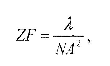
where NA is the numerical aperture and λ is the wavelength. - The imaging processing is implemented as a digital filter optimized to restore the MTF as a smooth function that decreases continuously to avoid overshoots, ringing and artifacts in the image.
- Noise amplification is frequently a problem in any sharpening filtering process. An optimized gain function that takes in account the power spectrum of noise similar to a Wiener's filter is applied to reduce the nose amplification. The gain function applied on the MTF depends of the object distance (see
Fig. 5 ). The MTF as a function of distance is acquired by a calibration process. The MTF is measured in the expected depth of field range by sampling step defocus distance less than 1/8 Fresnel's distance to avoid any under sampling loss of information. At each step of defocus distance, digital filtering is applied to restore the MTF on the processed image dependent upon the measured MTF. - The use of this filter requires knowledge of the defocus distance. The defocus distance can be measured by any of a number of devices and techniques for measuring the distance of an object. The filter parameter at a distance between two separate neighbor steps of focus distance can be calculated by the linear interpolation of the parameters of these two steps to reduce the error distance effect.
-
Fig. 12 shows the raw MTF and the enhanced MTF having a smooth shape to avoid overshoots and artifacts. The applied gain of the digital filter is optimized or enhanced to obtain the maximum MTF while controlling the gain on noise. - Unlike conventional lenses, lenses and other optical elements in accordance with the embodiments of the invention exploit spherical aberrations. Any lens design can be changed, in some cases even slightly, to get the required spherical aberration. The optical effect on DOF is effected by the spherical aberration. In the light of this disclosure, in theory, increasing depth of field can be independent of the lens design principle. A different optimization can be applied on any of a number of lens designs to produce the spherical aberration and obtain increased depth of field. Thus, increased depth of field arising from spherical aberrations extends well beyond the examples described herein and shown in the drawings, by way of example. Set out below are several examples involving this concept.
-
Fig. 9A is an example of an optical design without a spherical aberration, andFig. 9B contains two plots of characteristics of that lens with a spherical aberration. The optical path difference plot ofFig. 9B shows some residual aberrations, mainly secondary chromatic aberrations and aberrations of coma in the field. The aberrations are low compared to the wavelength as demonstrated in the MTF plot ofFig. 9B , which is close to the diffraction limit MTF. -
Fig. 10A is an example of the optical design like that ofFig. 9A but with the spherical aberration, arising from changes to thelens elements 1000, in accordance with an embodiment of the invention to produce the effect of increased depth of field.
The increased DOF arising from a spherical aberration is produced by changing slightly the radius of curvature of the twolenses 1000. -
Fig. 8 illustrates a Gauss lens having a spherical aberration in accordance with a further embodiment of the invention. This example illustrates that a "conventional" optical design can be modified to have a spherical aberration that increases the depth of field for the system. -
Fig. 11 illustrates a further optical system having a spherical aberration to increase or enhance depth of field. Light is input via anentrance pupil 1110 and passes through a plano-convex lens 1120 with the spherical aberration. The light focuses on animage sensor 1130. This simple design provides the required spherical aberration at F/6.6. Such a design, for example, matches well to working conditions for an iris recognition system or application. The light that is reflected from the eye pupil and collected through an entrance pupil or diaphragm 1110 (diameter of 8 mm located 11 mm) located in front of the plano-convex fused-silica lens 1120. However, thelens 1120 may be made from any glass or molted plastic. The location of thepupil 1110 is chosen at the place where coma aberration does not occur in the field at 11 mm ahead of the plane side of thelens 1110. Astigmatism is insignificant. The main aberrations are: - A spherical aberration. The mounting side is opposite of the minimum of the spherical aberration. The level of aberration with fused silica lens is 0.75 wave in near infrared at F/6.6 at a focal length of 50mm.
- A chromatic aberration. The
lens 1120 in this example is not corrected for chromatic aberration, which can be advantageous to increase the DOF when used with a broad spectrum lighting by erasing any zeroes in the MTF. Otherwise, the chromatic aberration is limited with an Abbe number > 60 to not damage the MTF by lateral color in the edge of field. - Curvature of field. The curvature of field has to be taken in account to set the best focus plane. Its effect is reduced by the gain on the depth of field.
-
Fig. 6 shows a simulated diffraction caustic without a spherical aberration (SA) and the associated DOF, andFig. 7 shows a caustic with an SA with increased DOF.Figs. 6 and 7 show the DOF enhancement with the spherical aberration. - Optical lenses and optical systems for increasing depth of focus have been described. While only a small number of embodiments of the invention have been described, in view of this disclosure, it will be apparent to one skilled in the art that modifications and/or substitutions can be made without departing from the scope and spirit of the invention.
Claims (26)
- An optical system, comprising:at least one optical element adapted to provide a spherical aberration in the range of about 0.2 wave to about 5 wave for increasing the depth of field of said optical system.
- The optical system according to claim 1, wherein said optical element comprises at least one lens.
- The optical system according to claim 1, wherein said increased depth of field is in the light wavelength range of about 300 nanometers to about 1200 nanometers.
- The optical system according to claim 1, wherein said depth of field is in the light wavelength range of about 700 nanometers to about 900 nanometers.
- The optical system according to claim 3 or 4, further comprising a system for digitally processing images to increase their Modulation Transfer Function (MTF) at spatial frequencies below the Nyquist Limit.
- An optical system for producing an image of an object, said optical system comprising:at least one of a lens and an optical element adapted to provide a chromatic aberration in the range of about 0.2 wave to 0.9 wave for increasing the depth of field of said system.
- The optical system according to claim 6, comprising a plurality of lenses.
- The optical system according to claim 6 or 7, comprising a plurality of optical elements.
- The optical system according to any one of claims 6 to 8, wherein said increased depth of field is in the light wavelength range of about 300 nanometers to about 1200 nanometers.
- The optical system according to claim 9, further comprising a system for digitally processing images to increase their Modulation Transfer Function (MTF) at spatial frequencies below the Nyquist Limit.
- The optical system according to claim 6, wherein said increased depth of field is in the light wavelength range of about 700 nanometers to about 900 nanometers.
- The optical system according to claim 11, wherein images produced by said optical system are digitally processed to increase their Modulation Transfer Function at spatial frequencies below the Nyquist Limit.
- The optical system according to claim 1, wherein said spherical aberration ranges from about 0.2 wave to about 0.9 wave and provides an increased depth of field and reduced Modulation Transfer Function at spatial frequencies below the Nyquist Limit, said increased depth of field and said reduced Modulation Transfer Function being further increased by digital image processing applied to an image obtained using said optical system.
- The optical system according to claim 1, wherein said spherical aberration range from about 0.2 wave to about 5 wave providing said increased depth of field, an image produced using said optical system having a reduced Modulation Transfer Function at spatial frequencies below the Nyquist Limit.
- The optical system according to claim 14, further comprising means for digital image processing of an image obtained using said system dependent upon a distance determined between an object and said optical system to increase the Modulation Transfer Function at spatial frequencies below the Nyquist Limit.
- The optical system according to claim 14, further comprising a device for determining the distance between said object and said optical system.
- The optical system according to claim 14, wherein a characteristic of an image is used to determine the distance between said object and said optical system.
- The optical system according to claim 17, wherein a local Edge Spread Function is used from a known object in said image to extract the distance between said object and said optical system.
- An optical system, comprising:at least one optical element adapted to having an axial chromatic aberration of about 0.4 to about 20 times the Fresnel distance in image space for increasing the depth of field while reducing the magnitude of non-central rings in a Point Spread Function and eliminating undesired zeros in a Modulation Transfer Function.
- The optical system according to claim 19, wherein said increased depth of field is in the light wavelength range of about 300 nanometers to about 1200 nanometers.
- The optical system according to claim 19, wherein said increased depth of field is in the light wavelength range of about 700 nanometers to about 900 nanometers.
- The optical system according to any one of claims 19 to 21, wherein an image obtained using said optical system is digitally processed to increase its Modulation Transfer Function at spatial frequencies below the Nyquist Limit.
- The optical system according to claim 22, wherein said digital processing is dependent upon the distance between an object and said optical system.
- The optical system according to claim 23, further comprising a device for determining the distance between said object and said optical system.
- The optical system according to claim 23, wherein a characteristic of an image is used to determine the distance between said object and said optical system.
- The optical system according to claim 25, wherein a local Edge Spread Function from a known object in the image is used to extract the object-to-image distance.
Priority Applications (7)
| Application Number | Priority Date | Filing Date | Title |
|---|---|---|---|
| EP07300936A EP1978394A1 (en) | 2007-04-06 | 2007-04-06 | Optical system for increasing depth of field |
| PCT/IB2008/001304 WO2008122888A2 (en) | 2007-04-06 | 2008-02-29 | Large depth-of-field imaging system and iris recognition system |
| US12/450,488 US8594388B2 (en) | 2007-04-06 | 2008-02-29 | Large depth-of-field imaging system and iris recogniton system |
| EP08751024A EP2140301A2 (en) | 2007-04-06 | 2008-02-29 | Large depth-of-field imaging system and iris recognition system |
| JP2010501614A JP5153862B2 (en) | 2007-04-06 | 2008-02-29 | High depth of field imaging system and iris authentication system |
| CN2008800156737A CN101681021B (en) | 2007-04-06 | 2008-02-29 | Large depth-of-field imaging system and iris recognition system |
| HK15109762.0A HK1209193A1 (en) | 2007-04-06 | 2015-10-06 | Single-lens extended depth-of-field imaging systems |
Applications Claiming Priority (1)
| Application Number | Priority Date | Filing Date | Title |
|---|---|---|---|
| EP07300936A EP1978394A1 (en) | 2007-04-06 | 2007-04-06 | Optical system for increasing depth of field |
Publications (1)
| Publication Number | Publication Date |
|---|---|
| EP1978394A1 true EP1978394A1 (en) | 2008-10-08 |
Family
ID=38430447
Family Applications (2)
| Application Number | Title | Priority Date | Filing Date |
|---|---|---|---|
| EP07300936A Withdrawn EP1978394A1 (en) | 2007-04-06 | 2007-04-06 | Optical system for increasing depth of field |
| EP08751024A Withdrawn EP2140301A2 (en) | 2007-04-06 | 2008-02-29 | Large depth-of-field imaging system and iris recognition system |
Family Applications After (1)
| Application Number | Title | Priority Date | Filing Date |
|---|---|---|---|
| EP08751024A Withdrawn EP2140301A2 (en) | 2007-04-06 | 2008-02-29 | Large depth-of-field imaging system and iris recognition system |
Country Status (6)
| Country | Link |
|---|---|
| US (1) | US8594388B2 (en) |
| EP (2) | EP1978394A1 (en) |
| JP (1) | JP5153862B2 (en) |
| CN (1) | CN101681021B (en) |
| HK (1) | HK1209193A1 (en) |
| WO (1) | WO2008122888A2 (en) |
Cited By (14)
| Publication number | Priority date | Publication date | Assignee | Title |
|---|---|---|---|---|
| EP2096483A1 (en) * | 2008-02-29 | 2009-09-02 | Global Bionic Optics Pty Ltd. | Single-lens extended depth-of-field imaging systems |
| EP2209300A2 (en) | 2009-01-16 | 2010-07-21 | Ricoh Company, Ltd. | Imaging system using enhanced spherical aberration and specifically sized fir filters |
| WO2010126568A1 (en) * | 2009-04-27 | 2010-11-04 | Fm-Assets Pty. Ltd. | Afocal galilean attachment lens with high pupil magnification |
| US20110074988A1 (en) * | 2009-09-30 | 2011-03-31 | Robinson M Dirk | Dual-Mode Extended Depth-of-Field Imaging Systems |
| WO2011058236A1 (en) * | 2009-11-16 | 2011-05-19 | Dxo Labs | Optical system, and related design method |
| CN102221746A (en) * | 2010-04-15 | 2011-10-19 | 财团法人工业技术研究院 | Projection system with extended depth of field and image processing method |
| WO2011134901A1 (en) * | 2010-04-27 | 2011-11-03 | Fm Assetts Pty Ltd | Thick single-lens extended depth-of-field imaging systems |
| US8294764B2 (en) | 2009-03-09 | 2012-10-23 | Gilles Mathieu | Extended depth-of-field surveillance imaging system |
| US8355211B2 (en) | 2005-08-11 | 2013-01-15 | FM-Assets Pty Ltd | Optical lens systems |
| US8488044B2 (en) | 2008-02-29 | 2013-07-16 | Global Bionic Optics Pty Ltd. | Single-lens extended depth-of-field imaging systems |
| EP2954837A1 (en) * | 2014-06-13 | 2015-12-16 | Morpho | Optical acquisition device for biometric systems |
| US9495590B1 (en) | 2015-04-23 | 2016-11-15 | Global Bionic Optics, Ltd. | Extended depth-of-field biometric system |
| WO2023113193A1 (en) * | 2021-12-15 | 2023-06-22 | Samsung Electronics Co., Ltd. | Device and method for extended depth of field imaging |
| US20240138674A1 (en) * | 2022-10-28 | 2024-05-02 | Optomed Plc | Ophthalmic apparatus and method of imaging retina |
Families Citing this family (50)
| Publication number | Priority date | Publication date | Assignee | Title |
|---|---|---|---|---|
| US7948550B2 (en) * | 2008-06-27 | 2011-05-24 | Ricoh Co., Ltd. | Electro-optic imaging system with aberrated triplet lens compensated by digital image processing |
| US8306279B2 (en) * | 2008-09-15 | 2012-11-06 | Eyelock, Inc. | Operator interface for face and iris recognition devices |
| CN102063610B (en) * | 2009-11-13 | 2013-08-28 | 鸿富锦精密工业(深圳)有限公司 | Image identification system and method thereof |
| US8274743B2 (en) * | 2010-04-08 | 2012-09-25 | Scaggs Michael J | Thermally compensating lens for high power lasers |
| JP6039156B2 (en) * | 2010-06-08 | 2016-12-07 | キヤノン株式会社 | Image processing apparatus, image processing method, and program |
| US9066072B2 (en) * | 2010-07-20 | 2015-06-23 | Semiconductor Components Industries, Llc | Systems and methods for calibrating image sensors |
| CN102566045A (en) * | 2010-12-20 | 2012-07-11 | 北京泰邦天地科技有限公司 | Optical imaging system |
| US9161690B2 (en) | 2011-03-10 | 2015-10-20 | Canon Kabushiki Kaisha | Ophthalmologic apparatus and control method of the same |
| CN103460108B (en) | 2011-03-31 | 2015-08-12 | 富士胶片株式会社 | Focus expansion optical system and EDoF camera system |
| US8836851B2 (en) * | 2011-06-01 | 2014-09-16 | Apple Inc. | Automatic exposure control based on multiple regions |
| US20150042776A1 (en) * | 2011-06-18 | 2015-02-12 | Morpho Trust USA,LLC | Systems And Methods For Detecting A Specular Reflection Pattern For Biometric Analysis |
| CN102880867B (en) * | 2011-09-06 | 2015-10-28 | 友尼嗯可缪尼体有限公司 | Optical fingerprint acquisition apparatus |
| CN102750726B (en) * | 2011-11-21 | 2017-09-19 | 新奥特(北京)视频技术有限公司 | A kind of method that Deep Canvas is realized based on OpenGL |
| CN102622586A (en) * | 2012-03-08 | 2012-08-01 | 湖南创远智能科技有限公司 | Iris-acquisition optical system for assisting focusing by utilizing visible light |
| WO2013162907A2 (en) * | 2012-04-23 | 2013-10-31 | Aoptix Technologies, Inc. | Handheld iris manager |
| CN102707405B (en) * | 2012-06-07 | 2014-04-02 | 北京天诚盛业科技有限公司 | Prime lens for collecting iris images |
| US9265458B2 (en) | 2012-12-04 | 2016-02-23 | Sync-Think, Inc. | Application of smooth pursuit cognitive testing paradigms to clinical drug development |
| US9380976B2 (en) | 2013-03-11 | 2016-07-05 | Sync-Think, Inc. | Optical neuroinformatics |
| EP3010392A4 (en) * | 2013-06-18 | 2017-01-25 | Delta ID Inc. | Iris imaging apparatus and methods for configuring an iris imaging apparatus |
| US10372982B2 (en) | 2014-01-06 | 2019-08-06 | Eyelock Llc | Methods and apparatus for repetitive iris recognition |
| US9443031B2 (en) * | 2014-02-13 | 2016-09-13 | Apteryx, Inc. | System and method to capture an image over the web |
| US9282237B2 (en) | 2014-07-17 | 2016-03-08 | Schlage Lock Company Llc | Multifocal iris recognition device |
| US9721186B2 (en) * | 2015-03-05 | 2017-08-01 | Nant Holdings Ip, Llc | Global signatures for large-scale image recognition |
| CN104834852B (en) * | 2015-05-04 | 2018-07-13 | 惠州Tcl移动通信有限公司 | A kind of method and system that mobile terminal is unlocked based on high quality eyeprint image |
| US20170061210A1 (en) * | 2015-08-26 | 2017-03-02 | Intel Corporation | Infrared lamp control for use with iris recognition authentication |
| CN105242375B (en) * | 2015-09-23 | 2019-05-17 | 武汉虹识技术有限公司 | A kind of long-focus iris recognition object lens |
| US10063849B2 (en) | 2015-09-24 | 2018-08-28 | Ouster, Inc. | Optical system for collecting distance information within a field |
| US9992477B2 (en) | 2015-09-24 | 2018-06-05 | Ouster, Inc. | Optical system for collecting distance information within a field |
| US9591111B1 (en) * | 2015-12-31 | 2017-03-07 | AAC Technologies Pte. Ltd. | Mobile terminal device |
| CN108780498B (en) * | 2016-01-06 | 2023-04-28 | Lg伊诺特有限公司 | Iris recognition camera system, lens module and iris recognition camera module |
| US10212366B2 (en) * | 2016-06-17 | 2019-02-19 | Fotonation Limited | Iris image acquisition system |
| JP6419115B2 (en) * | 2016-07-19 | 2018-11-07 | キヤノン株式会社 | Image processing apparatus, image processing method, and program |
| KR102732412B1 (en) * | 2016-07-29 | 2024-11-22 | 삼성전자주식회사 | Optical lens assembly and electronic apparatus having the same |
| CA3035094A1 (en) | 2016-08-24 | 2018-03-01 | Ouster, Inc. | Optical system for collecting distance information within a field |
| CN108132530B (en) * | 2017-03-03 | 2022-01-25 | 中国北方车辆研究所 | Large-depth-of-field optical method and system based on aberration balance and control |
| DE102017108874A1 (en) * | 2017-04-26 | 2018-10-31 | Carl Zeiss Ag | Material testing with structured lighting |
| KR102706360B1 (en) | 2017-05-15 | 2024-09-12 | 아우스터, 인크. | Optical imaging transmitter with brightness enhancement |
| US10430644B2 (en) * | 2017-06-06 | 2019-10-01 | Global Bionic Optics Ltd. | Blended iris and facial biometric system |
| WO2019036751A1 (en) * | 2017-08-22 | 2019-02-28 | Seeing Machines Limited | Enhanced video-based driver monitoring using phase detect sensors |
| US10969490B2 (en) | 2017-12-07 | 2021-04-06 | Ouster, Inc. | Light ranging system with opposing circuit boards |
| US11209633B2 (en) * | 2018-02-26 | 2021-12-28 | Fotonation Limited | Iris image acquisition system |
| US10739189B2 (en) | 2018-08-09 | 2020-08-11 | Ouster, Inc. | Multispectral ranging/imaging sensor arrays and systems |
| US11473970B2 (en) | 2018-08-09 | 2022-10-18 | Ouster, Inc. | Subpixel apertures for channels in a scanning sensor array |
| JP6720267B2 (en) * | 2018-10-11 | 2020-07-08 | キヤノン株式会社 | Image processing apparatus, image processing method, and program |
| EP3657909A1 (en) * | 2018-11-21 | 2020-05-27 | BrainLit AB | Head worn electronic device |
| CN109491176A (en) * | 2019-01-09 | 2019-03-19 | 凌云光技术集团有限责任公司 | Big depth field imaging system and method based on prismatic decomposition |
| DE102019126419A1 (en) * | 2019-05-08 | 2020-11-12 | Docter Optics Se | Device for the optical imaging of features of a hand |
| US11568540B2 (en) * | 2019-10-07 | 2023-01-31 | Optos Plc | System, method, and computer-readable medium for rejecting full and partial blinks for retinal tracking |
| EP4467065A1 (en) * | 2023-05-25 | 2024-11-27 | Deep Obverse Taiwan Inc. | Electronic device, physiological state detection device, and physiological state detection method applied to electronic device |
| CN119379759B (en) * | 2024-12-31 | 2025-04-04 | 新光维医疗科技(苏州)股份有限公司 | Method and device for evaluating optical depth of field of endoscope, computer equipment and medium |
Citations (3)
| Publication number | Priority date | Publication date | Assignee | Title |
|---|---|---|---|---|
| US20060050409A1 (en) * | 2004-09-03 | 2006-03-09 | Automatic Recognition & Control, Inc. | Extended depth of field using a multi-focal length lens with a controlled range of spherical aberration and a centrally obscured aperture |
| US20060164736A1 (en) * | 2005-01-27 | 2006-07-27 | Olmstead Bryan L | Imaging system with a lens having increased light collection efficiency and a deblurring equalizer |
| WO2006083488A2 (en) * | 2005-01-31 | 2006-08-10 | Psc Scanning, Inc. | Extended depth of field imaging system using chromatic aberration |
Family Cites Families (23)
| Publication number | Priority date | Publication date | Assignee | Title |
|---|---|---|---|---|
| JPH027678A (en) | 1988-06-27 | 1990-01-11 | Hitachi Ltd | Contour compensation circuit |
| JPH06162187A (en) | 1992-11-17 | 1994-06-10 | Olympus Optical Co Ltd | Out-of focus image restoring device |
| JPH0784179A (en) | 1993-07-19 | 1995-03-31 | Asahi Optical Co Ltd | Endoscope objective lens |
| DE19527255A1 (en) | 1994-08-17 | 1996-02-22 | Eastman Kodak Co | In visual spectral range working single-lens camera |
| US6911638B2 (en) * | 1995-02-03 | 2005-06-28 | The Regents Of The University Of Colorado, A Body Corporate | Wavefront coding zoom lens imaging systems |
| US7218448B1 (en) | 1997-03-17 | 2007-05-15 | The Regents Of The University Of Colorado | Extended depth of field optical systems |
| US5808726A (en) | 1995-02-28 | 1998-09-15 | Canon Kabushiki Kaisha | Distance measurement apparatus |
| WO1997021188A1 (en) | 1995-12-04 | 1997-06-12 | David Sarnoff Research Center, Inc. | Wide field of view/narrow field of view recognition system and method |
| AU3779299A (en) | 1998-05-01 | 1999-11-23 | University Technology Corporation | Extended depth of field optical systems |
| EP1204283A1 (en) * | 2000-11-06 | 2002-05-08 | Telefonaktiebolaget L M Ericsson (Publ) | Cellular radio network reusing frequencies |
| US7095901B2 (en) | 2001-03-15 | 2006-08-22 | Lg Electronics, Inc. | Apparatus and method for adjusting focus position in iris recognition system |
| US7151246B2 (en) * | 2001-07-06 | 2006-12-19 | Palantyr Research, Llc | Imaging system and methodology |
| WO2003076984A1 (en) | 2002-03-14 | 2003-09-18 | Ramot At Tel Aviv University Ltd. | All optical extended depth-of-field imaging system |
| US7206435B2 (en) | 2002-03-26 | 2007-04-17 | Honda Giken Kogyo Kabushiki Kaisha | Real-time eye detection and tracking under various light conditions |
| JP2004226729A (en) | 2003-01-23 | 2004-08-12 | Matsushita Electric Ind Co Ltd | Authentication target imaging device |
| DE10338472B4 (en) | 2003-08-21 | 2020-08-06 | Carl Zeiss Meditec Ag | Optical imaging system with extended depth of field |
| US7593550B2 (en) | 2005-01-26 | 2009-09-22 | Honeywell International Inc. | Distance iris recognition |
| US7336806B2 (en) | 2004-03-22 | 2008-02-26 | Microsoft Corporation | Iris-based biometric identification |
| US7365917B2 (en) | 2004-08-16 | 2008-04-29 | Xceed Imaging Ltd. | Optical method and system for extended depth of focus |
| US7061693B2 (en) | 2004-08-16 | 2006-06-13 | Xceed Imaging Ltd. | Optical method and system for extended depth of focus |
| WO2007011375A1 (en) * | 2004-09-13 | 2007-01-25 | Cdm Optics, Inc. | Iris image capture devices and associated systems |
| JP4563836B2 (en) * | 2005-02-14 | 2010-10-13 | 株式会社リコー | Image forming apparatus |
| US7729603B2 (en) * | 2005-02-28 | 2010-06-01 | Siimpel Corporation | Resolution adjustment for miniature camera |
-
2007
- 2007-04-06 EP EP07300936A patent/EP1978394A1/en not_active Withdrawn
-
2008
- 2008-02-29 WO PCT/IB2008/001304 patent/WO2008122888A2/en not_active Ceased
- 2008-02-29 US US12/450,488 patent/US8594388B2/en not_active Expired - Fee Related
- 2008-02-29 JP JP2010501614A patent/JP5153862B2/en not_active Expired - Fee Related
- 2008-02-29 CN CN2008800156737A patent/CN101681021B/en not_active Expired - Fee Related
- 2008-02-29 EP EP08751024A patent/EP2140301A2/en not_active Withdrawn
-
2015
- 2015-10-06 HK HK15109762.0A patent/HK1209193A1/en unknown
Patent Citations (3)
| Publication number | Priority date | Publication date | Assignee | Title |
|---|---|---|---|---|
| US20060050409A1 (en) * | 2004-09-03 | 2006-03-09 | Automatic Recognition & Control, Inc. | Extended depth of field using a multi-focal length lens with a controlled range of spherical aberration and a centrally obscured aperture |
| US20060164736A1 (en) * | 2005-01-27 | 2006-07-27 | Olmstead Bryan L | Imaging system with a lens having increased light collection efficiency and a deblurring equalizer |
| WO2006083488A2 (en) * | 2005-01-31 | 2006-08-10 | Psc Scanning, Inc. | Extended depth of field imaging system using chromatic aberration |
Non-Patent Citations (1)
| Title |
|---|
| SMITH WARREN J: "Modern optical engineering - The design of optical systems - Second edition", 1990, MC GRAW - HILL BOOK COMPANY, NEW YORK, NY, US, ISBN: 0-07-059174-1, article "The effect of lens shape and stop positions on the aberrations", pages: 70 - 74 * |
Cited By (25)
| Publication number | Priority date | Publication date | Assignee | Title |
|---|---|---|---|---|
| US8355211B2 (en) | 2005-08-11 | 2013-01-15 | FM-Assets Pty Ltd | Optical lens systems |
| EP2096483A1 (en) * | 2008-02-29 | 2009-09-02 | Global Bionic Optics Pty Ltd. | Single-lens extended depth-of-field imaging systems |
| WO2009106996A3 (en) * | 2008-02-29 | 2009-10-22 | Global Bionic Optics, Pty Ltd | Single-lens extended depth-of-field imaging systems |
| US8488044B2 (en) | 2008-02-29 | 2013-07-16 | Global Bionic Optics Pty Ltd. | Single-lens extended depth-of-field imaging systems |
| EP2209300A3 (en) * | 2009-01-16 | 2012-03-07 | Ricoh Company, Ltd. | Imaging system using enhanced spherical aberration and specifically sized fir filters |
| EP2209300A2 (en) | 2009-01-16 | 2010-07-21 | Ricoh Company, Ltd. | Imaging system using enhanced spherical aberration and specifically sized fir filters |
| US8294764B2 (en) | 2009-03-09 | 2012-10-23 | Gilles Mathieu | Extended depth-of-field surveillance imaging system |
| WO2010126568A1 (en) * | 2009-04-27 | 2010-11-04 | Fm-Assets Pty. Ltd. | Afocal galilean attachment lens with high pupil magnification |
| GB2482099A (en) * | 2009-04-27 | 2012-01-18 | Fm Assets Pty Ltd | Afocal galilean attachment lens with high pupil magnification |
| CN102625920A (en) * | 2009-04-27 | 2012-08-01 | Fm-资产控股有限公司 | Afocal Galilean Attachment Lens with High Pupil Magnification |
| US20110074988A1 (en) * | 2009-09-30 | 2011-03-31 | Robinson M Dirk | Dual-Mode Extended Depth-of-Field Imaging Systems |
| US8248511B2 (en) * | 2009-09-30 | 2012-08-21 | Ricoh Co., Ltd. | Dual-mode extended depth-of-field imaging systems |
| WO2011058236A1 (en) * | 2009-11-16 | 2011-05-19 | Dxo Labs | Optical system, and related design method |
| CN102221746A (en) * | 2010-04-15 | 2011-10-19 | 财团法人工业技术研究院 | Projection system with extended depth of field and image processing method |
| CN102221746B (en) * | 2010-04-15 | 2014-01-22 | 财团法人工业技术研究院 | Projection system and image processing method for extended depth of field |
| US8416334B2 (en) | 2010-04-27 | 2013-04-09 | Fm-Assets Pty Ltd. | Thick single-lens extended depth-of-field imaging systems |
| WO2011134901A1 (en) * | 2010-04-27 | 2011-11-03 | Fm Assetts Pty Ltd | Thick single-lens extended depth-of-field imaging systems |
| EP2954837A1 (en) * | 2014-06-13 | 2015-12-16 | Morpho | Optical acquisition device for biometric systems |
| FR3022377A1 (en) * | 2014-06-13 | 2015-12-18 | Morpho | OPTICAL ACQUISITION DEVICE FOR BIOMETRIC SYSTEMS |
| US10523863B2 (en) | 2014-06-13 | 2019-12-31 | Idemia Identity & Security France | Optical acquisition device for biometric systems |
| US9495590B1 (en) | 2015-04-23 | 2016-11-15 | Global Bionic Optics, Ltd. | Extended depth-of-field biometric system |
| US9727783B2 (en) | 2015-04-23 | 2017-08-08 | Global Bionic Optics, LTD | Extended depth-of-field biometric system |
| WO2023113193A1 (en) * | 2021-12-15 | 2023-06-22 | Samsung Electronics Co., Ltd. | Device and method for extended depth of field imaging |
| US20240138674A1 (en) * | 2022-10-28 | 2024-05-02 | Optomed Plc | Ophthalmic apparatus and method of imaging retina |
| US12484777B2 (en) | 2022-10-28 | 2025-12-02 | Optomed Plc | Ophthalmic apparatus and method of alignment of ophthalmic apparatus |
Also Published As
| Publication number | Publication date |
|---|---|
| US8594388B2 (en) | 2013-11-26 |
| WO2008122888A2 (en) | 2008-10-16 |
| JP2010524073A (en) | 2010-07-15 |
| CN101681021A (en) | 2010-03-24 |
| WO2008122888A3 (en) | 2009-03-19 |
| JP5153862B2 (en) | 2013-02-27 |
| CN101681021B (en) | 2012-02-01 |
| US20100110275A1 (en) | 2010-05-06 |
| HK1209193A1 (en) | 2016-03-24 |
| EP2140301A2 (en) | 2010-01-06 |
Similar Documents
| Publication | Publication Date | Title |
|---|---|---|
| EP1978394A1 (en) | Optical system for increasing depth of field | |
| KR101610975B1 (en) | Single-lens extended depth-of-field imaging systems | |
| US10880473B2 (en) | Imaging apparatus with focus breathing correction | |
| US8149319B2 (en) | End-to-end design of electro-optic imaging systems for color-correlated objects | |
| CN207301457U (en) | Imaging len and camera device | |
| CN106680976B (en) | Pick-up lens | |
| WO2011060940A2 (en) | Fixed focal length optical lens architecture providing a customized depth of focus optical system | |
| US20170123192A1 (en) | Near-infrared imaging lens | |
| US8416334B2 (en) | Thick single-lens extended depth-of-field imaging systems | |
| EP2096483A1 (en) | Single-lens extended depth-of-field imaging systems | |
| WO2011027536A1 (en) | Optical device, image capturing device using same, and image capturing system | |
| JPWO2013014913A1 (en) | Imaging lens and imaging apparatus using the same | |
| EP2328006A1 (en) | Task-based imaging systems | |
| JP4658162B2 (en) | Imaging apparatus and electronic apparatus | |
| CN115248496B (en) | High-definition optical lens and high-performance laser radar | |
| Fontbonne et al. | Experimental validation of hybrid optical–digital imaging system for extended depth-of-field based on co-optimized binary phase masks | |
| HK1123855A (en) | Optical system for increasing depth of field | |
| ES3009182T3 (en) | Method and device for obtaining an extended depth of field image | |
| JP4932208B2 (en) | Image reading lens and image reading apparatus | |
| JP7047075B2 (en) | Endoscope objective optical system, image pickup device and endoscope | |
| JP2006094469A (en) | Imaging apparatus and imaging method | |
| JP7501985B2 (en) | Endoscopic imaging device | |
| JP2019015788A (en) | Imaging optical system and imaging apparatus having the same | |
| JP2009139698A (en) | Imaging system, imaging apparatus, portable terminal apparatus, in-vehicle apparatus and medical apparatus with imaging system | |
| JP2009139697A (en) | Imaging system, and imaging apparatus, portable terminal apparatus, in-vehicle apparatus and medical apparatus with imaging system, and method for manufacturing imaging system |
Legal Events
| Date | Code | Title | Description |
|---|---|---|---|
| PUAI | Public reference made under article 153(3) epc to a published international application that has entered the european phase |
Free format text: ORIGINAL CODE: 0009012 |
|
| AK | Designated contracting states |
Kind code of ref document: A1 Designated state(s): AT BE BG CH CY CZ DE DK EE ES FI FR GB GR HU IE IS IT LI LT LU LV MC MT NL PL PT RO SE SI SK TR |
|
| AX | Request for extension of the european patent |
Extension state: AL BA HR MK RS |
|
| 17P | Request for examination filed |
Effective date: 20090406 |
|
| 17Q | First examination report despatched |
Effective date: 20090513 |
|
| AKX | Designation fees paid |
Designated state(s): AT BE BG CH CY CZ DE DK EE ES FI FR GB GR HU IE IS IT LI LT LU LV MC MT NL PL PT RO SE SI SK TR |
|
| REG | Reference to a national code |
Ref country code: HK Ref legal event code: DE Ref document number: 1123855 Country of ref document: HK |
|
| STAA | Information on the status of an ep patent application or granted ep patent |
Free format text: STATUS: THE APPLICATION IS DEEMED TO BE WITHDRAWN |
|
| 18D | Application deemed to be withdrawn |
Effective date: 20131031 |
|
| REG | Reference to a national code |
Ref country code: HK Ref legal event code: WD Ref document number: 1123855 Country of ref document: HK |