JP4932208B2 - Image reading lens and image reading apparatus - Google Patents
Image reading lens and image reading apparatus Download PDFInfo
- Publication number
- JP4932208B2 JP4932208B2 JP2005286429A JP2005286429A JP4932208B2 JP 4932208 B2 JP4932208 B2 JP 4932208B2 JP 2005286429 A JP2005286429 A JP 2005286429A JP 2005286429 A JP2005286429 A JP 2005286429A JP 4932208 B2 JP4932208 B2 JP 4932208B2
- Authority
- JP
- Japan
- Prior art keywords
- lens
- image reading
- focal length
- image
- object side
- Prior art date
- Legal status (The legal status is an assumption and is not a legal conclusion. Google has not performed a legal analysis and makes no representation as to the accuracy of the status listed.)
- Expired - Fee Related
Links
Images


Landscapes
- Lenses (AREA)
Description
本発明は、例えばファクシミリやイメージスキャナ等の画像読取装置の光学系に用いられる画像読取用の結像レンズに関し、特に画像縮小用もしくは画像拡大用の画像読取用レンズおよびそれを用いた画像読取装置に関する。 The present invention relates to an image reading imaging lens used in an optical system of an image reading apparatus such as a facsimile or an image scanner, and more particularly to an image reading lens for image reduction or image enlargement and an image reading apparatus using the same. About.
原稿画像をCCD(Charge Coupled Device:電荷結合素子)等の撮像素子に縮小もしくは拡大して結像させるタイプのファクシミリやイメージスキャナ等に用いられる画像読取用の結像レンズは、使用される結像倍率において高い解像力を持っていること、周辺光量が多いこと、歪曲収差が小さいことが基本的に要求されている。またその他にも、近年の光学装置全体のコンパクト化および低コスト化の要求に伴い、そのサイズをコンパクトなものとし、製造コストを安価なものとすることも求められている。このような要求に対応し得る結像レンズとして、特許文献1に記載の読取用レンズが知られている。
特許文献1に記載の読取用レンズは、1枚のガラスレンズと2枚の樹脂レンズとの3枚構成で、樹脂レンズの少なくとも1面に色収差補正効果を有する正の回折レンズ面を形成することにより、色収差を良好に補正しつつコンパクトで安価な光学系を達成している。しかしながら、特許文献1に記載の読取用レンズでは、実施例として半画角が23度を超えるような広画角のものが開示されているものの、実際には残存収差量が大きく、近年のさらなる高解像化とそれに伴う撮像素子の微細化に耐えうる性能とは言い難いものであった。またこの読取用レンズでは、回折レンズ面の回折作用のパワーが比較的大きく、そのため回折レンズ面の有効径に対する輪帯の数が多いことが推測されるが、加工性を考慮すると輪帯数は少ない方が望ましい。
The reading lens described in
本発明はかかる問題点に鑑みてなされたもので、その目的は、少ないレンズ枚数でコンパクトで安価なレンズ系を実現すると共に、広画角化と読取画像の高品質化を図ることができ、特に軸上色収差と倍率色収差とを同時に良好に補正できるようにした画像読取用レンズおよび画像読取装置を提供することにある。 The present invention has been made in view of such problems, and the object thereof is to realize a compact and inexpensive lens system with a small number of lenses, and to achieve a wide angle of view and high quality of a read image. In particular, it is an object of the present invention to provide an image reading lens and an image reading apparatus that can satisfactorily correct axial chromatic aberration and lateral chromatic aberration at the same time.
本発明による画像読取用レンズは、物体側から順に、物体側に凸面を向けた正のメニスカスレンズからなる第1レンズと、物体側に凹面を向けた負のメニスカスレンズからなる第2レンズと、像側に凸面を向けた正のレンズからなる第3レンズとが配設され、第2レンズの物体側の面に回折レンズ面が形成され、さらに以下の条件を満足するように構成されているものである。
0.012<L/f<0.04 ……(5)
ただし、
L:最外画角最外光線が第2レンズを通過する光路長
f:全系の焦点距離
とする。
An image reading lens according to the present invention includes, in order from the object side, a first lens composed of a positive meniscus lens having a convex surface facing the object side, a second lens composed of a negative meniscus lens having a concave surface facing the object side, A third lens composed of a positive lens having a convex surface facing the image side, a diffractive lens surface is formed on the object side surface of the second lens, and is configured to satisfy the following conditions: Is.
0.012 <L / f <0.04 (5)
However,
L: the optical path length through which the outermost ray of the outermost field angle passes through the second lens
f: Focal length of the entire system
And
本発明による画像読取装置は、上記本発明による画像読取用レンズを備えたものである。 An image reading apparatus according to the present invention includes the image reading lens according to the present invention.
本発明による画像読取用レンズおよび画像読取装置では、3枚構成という少ないレンズ枚数でありながら、第2レンズの物体側の面に回折レンズ面を形成していることにより、広画角化と読取画像の高品質化を図ることができるように、特に軸上色収差と倍率色収差とが同時に良好に補正される。
そしてさらに、要求される仕様等に応じて次の好ましい条件を適宜採用して満足することで、画像読取に適したより良好な性能が得られる。
In the image reading lens and the image reading apparatus according to the present invention, the diffractive lens surface is formed on the object-side surface of the second lens while the number of lenses is small, that is, the three-lens configuration. In particular, the longitudinal chromatic aberration and the lateral chromatic aberration are favorably corrected at the same time so that the quality of the image can be improved.
Furthermore, the following preferable conditions are appropriately adopted according to the required specifications and the like to be satisfied, so that better performance suitable for image reading can be obtained.
本発明による画像読取用レンズは、以下の条件を満足するように構成されていることが好ましい。
3.6<|f12/f3|<6.4 ……(1)
M/D<3.0 ……(2)
(ν1+ν3)/2−ν2>21 ……(3)
ただし、
f12:第1レンズと第2レンズの合成焦点距離
f3:第3レンズの焦点距離
M:回折レンズ面の輪帯数
D:回折レンズ面の有効径(mm)
νi:第iレンズの分散
とする。
The image reading lens according to the present invention is preferably configured to satisfy the following conditions.
3.6 <| f12 / f3 | <6.4 (1)
M / D <3.0 (2)
(Ν1 + ν3) / 2−ν2> 21 (3)
However,
f12: Composite focal length of the first lens and the second lens f3: Focal length of the third lens M: Number of ring zones of the diffractive lens surface D: Effective diameter (mm) of the diffractive lens surface
ν i is the dispersion of the i-th lens.
本発明による画像読取用レンズはまた、以下の条件を満足するように構成されていることが好ましい。
0.62<|(f2・χ1)/(f1・χ2)|<0.98 ……(4)
ただし、
f1:第1レンズの焦点距離
f2:第2レンズの焦点距離
χi:第iレンズの次式で定義される関数
χi=αi−(1/(ni−1))・(dn/dt)i
αi:第iレンズの線膨張係数
ni:第iレンズのe線の屈折率
(dn/dt)i:第iレンズのe線の屈折率温度係数
とする。
The image reading lens according to the present invention is also preferably configured to satisfy the following conditions.
0.62 <| (f2 · χ1) / (f1 · χ2) | <0.98 (4 )
However it was,
f1: Focal length of the first lens f2: Focal length of the second lens χi: Function defined by the following expression of the i-th lens χi = αi− (1 / (ni−1)) · (dn / dt) i
.alpha.i: linear expansion coefficient of the i-th lens ni: refractive index of the e-line of the i-th lens (dn / dt) i: refractive index temperature coefficient of the e-line of the i-th lens
And
本発明による画像読取用レンズはまた、第1レンズと第2レンズとの間に配設された絞りをさらに備えていても良い。 The image reading lens according to the present invention may further include a diaphragm disposed between the first lens and the second lens.
また本発明による画像読取用レンズにおいて、第1レンズと第2レンズは樹脂レンズであることが好ましい。 In the image reading lens according to the present invention, the first lens and the second lens are preferably resin lenses.
本発明の画像読取用レンズまたは画像読取装置によれば、物体側から順に、物体側に凸面を向けた正のメニスカスレンズからなる第1レンズと、物体側に凹面を向けた負のメニスカスレンズからなる第2レンズと、像側に凸面を向けた正のレンズからなる第3レンズとを配設し、第2レンズの物体側の面に回折レンズ面を形成するようにしたので、3枚構成という少ないレンズ枚数でコンパクトで安価なレンズ系を実現しつつ、広画角化と読取画像の高品質化を図ることができ、特に軸上色収差と倍率色収差とを同時に良好に補正できる。 According to the image reading lens or the image reading apparatus of the present invention, in order from the object side, the first lens is a positive meniscus lens having a convex surface facing the object side, and the negative meniscus lens having a concave surface facing the object side. And a third lens composed of a positive lens having a convex surface facing the image side, and a diffractive lens surface is formed on the object side surface of the second lens. While realizing a compact and inexpensive lens system with a small number of lenses, it is possible to widen the angle of view and to improve the quality of the read image. In particular, axial chromatic aberration and lateral chromatic aberration can be corrected well at the same time.
以下、本発明の実施の形態について図面を参照して詳細に説明する。
図1は、本発明の一実施の形態に係る画像読取用レンズの一構成例を示している。この構成例は、後述の第1の数値実施例(図2(A),図2(B))のレンズ構成に対応している。図1において、符号Riは、最も物体側の構成要素の面を1番目として、像側(結像側)に向かうに従い順次増加するようにして符号を付したi番目の面の曲率半径を示す。符号diは、i番目の面とi+1番目の面との光軸Z1上の面間隔を示す。
Hereinafter, embodiments of the present invention will be described in detail with reference to the drawings.
FIG. 1 shows a configuration example of an image reading lens according to an embodiment of the present invention. This configuration example corresponds to the lens configuration of a first numerical example (FIGS. 2A and 2B) described later. In FIG. 1, the symbol Ri indicates the radius of curvature of the i-th surface that is numbered so as to increase sequentially toward the image side (imaging side), with the most object-side component surface being first. . A symbol di indicates a surface interval on the optical axis Z1 between the i-th surface and the i + 1-th surface.
この画像読取用レンズ1は、例えばファクシミリやイメージスキャナ等の画像読取装置の光学系に好適に用いられるものである。この画像読取用レンズ1は、光軸Z1に沿って物体側から順に、物体側に凸面を向けた正のメニスカスレンズからなる第1レンズL1と、物体側に凹面を向けた負のメニスカスレンズからなる第2レンズL2と、像側に凸面を向けた正のレンズからなる第3レンズL3とが配設されている。第2レンズL2の物体側の面は回折レンズ面とされている。第1レンズL1と第2レンズL2との間には絞りStが配設されている。第1レンズL1と第2レンズL2は例えば両面が非球面の樹脂レンズ、第3レンズL3はガラスレンズであることが好ましい。
The
この画像読取用レンズ1の最も物体側(画像の読み取り側)と、最も結像面側(撮像面側)とには平板状の光学部材11,12が配設されている。また結像面には、図示しないCCD等の撮像素子が配置される。光学部材11,12は、後述する画像読取装置における原稿載置台としてのガラス板や各種光学フィルタ、CCD等の撮像素子のカバーガラスなどである。
Flat
この画像読取用レンズ1は、以下の条件を満足するように構成されていることが好ましい。
3.6<|f12/f3|<6.4 ……(1)
M/D<3.0 ……(2)
(ν1+ν3)/2−ν2>21 ……(3)
ただし、
f12:第1レンズL1と第2レンズL2の合成焦点距離
f3:第3レンズL3の焦点距離
M:回折レンズ面の輪帯数
D:回折レンズ面の有効径(mm)
νi:第iレンズの分散
The
3.6 <| f12 / f3 | <6.4 (1)
M / D <3.0 (2)
(Ν1 + ν3) / 2−ν2> 21 (3)
However,
f12: Combined focal length of the first lens L1 and the second lens L2 f3: Focal length of the third lens L3 M: Number of ring zones of the diffractive lens surface D: Effective diameter (mm) of the diffractive lens surface
νi: i-th lens dispersion
この画像読取用レンズ1はまた、以下の条件を満足するように構成されていることが好ましい。
0.62<|(f2・χ1)/(f1・χ2)|<0.98 ……(4)
0.012<L/f<0.04 ……(5)
ただし、
f1:第1レンズL1の焦点距離
f2:第2レンズL2の焦点距離
L:最外画角最外光線が第2レンズL2を通過する光路長
f:全系の焦点距離
The
0.62 <| (f2 · χ1) / (f1 · χ2) | <0.98 (4)
0.012 <L / f <0.04 (5)
However,
f1: Focal length of the first lens L1 f2: Focal length of the second lens L2 L: Optical path length through which the outermost ray at the outermost field angle passes through the second lens L2 f: Focal length of the entire system
特に条件式(4)において、χi(χ1またはχ2)は第iレンズの次式で定義される関数を示す。
χi=αi−(1/(ni−1))・(dn/dt)i
αi:第iレンズの線膨張係数
ni:第iレンズのe線の屈折率
(dn/dt)i:第iレンズのe線の屈折率温度係数
Particularly in the conditional expression (4), χi (χ1 or χ2) represents a function defined by the following expression of the i-th lens.
χi = αi− (1 / (ni−1)) · (dn / dt) i
αi: Linear expansion coefficient of i-th lens ni: Refractive index of e-line of i-th lens (dn / dt) i: Refractive index temperature coefficient of e-line of i-th lens
図18は、この画像読取用レンズ1を用いた画像読取装置の一構成例を示している。この画像読取装置10は、反射原稿式のイメージスキャナであり、読み取り対象の原稿2が載置される原稿載置台3と、原稿載置台3上の原稿2へ向けて照明光を発する例えばライン状の光源5と、原稿2の画像を取り込むCCD等の撮像素子4とを備えている。画像読取用レンズ1は、原稿2と撮像素子4との間に配置される。この画像読取装置10では、光源5が、その延在方向と直交する方向(矢印Aで示した方向)に沿って原稿載置台3の上を平行移動しながら原稿2を全面に亘って順次照射する。原稿2からの反射光は、読取用レンズ1によって撮像素子4上に結像され、撮像素子4によって画像情報として取り込まれる。
FIG. 18 shows a configuration example of an image reading apparatus using the
なお、この画像読取用レンズ1は、反射原稿式に限らず透過原稿式の画像読取装置にも適用可能である。透過原稿式の場合、原稿2として例えばネガフィルムまたはポジフィルム等の透過原稿が透明な原稿載置台に載置される。そして、原稿載置台の裏面側から透過原稿に向けて照明光が照射され、その透過光が読取レンズ1によって撮像素子4上に結像され、撮像素子4によって画像情報として取り込まれる。
The
次に、以上のように構成された画像読取用レンズ1の作用および効果を説明する。
この画像読取用レンズ1では、3枚構成という少ないレンズ枚数でありながら、第2レンズL2の物体側の面に回折レンズ面を形成していることにより、広画角化と読取画像の高品質化を図ることができるように、特に軸上色収差と倍率色収差とが同時に良好に補正される。回折レンズ面は、倍率色収差を小さく保ちつつ色収差の2次スペクトルを小さくするために、絞り面の直前あるいは直後に配置されることが望ましい。この画像読取用レンズ1では、絞りStの直後の面に回折レンズ面が形成されているので、色収差を良好に補正できる。また、第1レンズL1と第2レンズL2を樹脂レンズにすることで、非球面および回折レンズ面の加工がし易くなる。そしてさらに、要求される仕様等に応じて上記各条件式を適宜採用して満足することで、画像読取に適したより良好な性能が得られる。
Next, operations and effects of the
In this
条件式(1)は、第1レンズL1と第2レンズL2との合成焦点距離f12とガラスレンズである第3レンズL3の焦点距離f3との適切な比を規定するものである。条件式(1)の下限を下回ると、第1レンズL1と第2レンズL2とを樹脂レンズにした場合において、そのパワーが小さくなるため温度変化によるピント位置の移動量を小さくできる反面、収差補正が困難になり必要な解像性能を得られなくなるので好ましくない。上限を上回ると収差補正には有利であるが、温度変化によるピント移動量が大きくなるので好ましくない。 Conditional expression (1) defines an appropriate ratio between the combined focal length f12 of the first lens L1 and the second lens L2 and the focal length f3 of the third lens L3 that is a glass lens. If the lower limit of conditional expression (1) is not reached, when the first lens L1 and the second lens L2 are made of resin lenses, the power decreases, so that the amount of movement of the focus position due to temperature change can be reduced, but aberration correction Is not preferable because the required resolution performance cannot be obtained. If the upper limit is exceeded, it is advantageous for aberration correction, but it is not preferable because the amount of focus movement due to temperature change becomes large.
条件式(2)は、回折レンズ面の輪帯数に関するものであって、上限を上回ると収差補正には有利であるが有効径に対する輪帯数が多くなり加工性が悪くなるので好ましくない。 Conditional expression (2) relates to the number of zonal zones of the diffractive lens surface. If the upper limit is exceeded, it is advantageous for aberration correction, but the number of zonal zones with respect to the effective diameter increases and workability deteriorates.
条件式(3)は、正のパワーを持つ第1レンズL1および第3レンズL3の分散と、負のパワーを持つ第2レンズL2の分散との適切な関係を規定するものである。条件式(3)の下限を下回ると色収差補正に関する回折レンズ面への依存度が高くなり、加工性の確保が困難になるので好ましくない。 Conditional expression (3) defines an appropriate relationship between the dispersion of the first lens L1 and the third lens L3 having positive power and the dispersion of the second lens L2 having negative power. If the lower limit of conditional expression (3) is not reached, the dependence on the diffractive lens surface with respect to chromatic aberration correction becomes high and it becomes difficult to ensure processability, which is not preferable.
条件式(4)は、第1レンズL1と第2レンズL2との各パワーφ1(=1/f1),φ2(=1/f2)と、
α−(1/(n−1))・dn/dt
で定義される各レンズの温度特性に関する関数χ1,χ2とのレンズごとの積の比を規定するものである。条件式(4)の範囲の下限を下回る場合も上限を上回る場合も、温度変化によるピント位置の移動量が大きくなり良好な性能が得られない。より良好な性能を得るためには、
0.7<|(f2・χ1)/(f1・χ2)|<0.85 ……(4A)
の範囲であることが望ましい。
Conditional expression (4) indicates that the powers φ1 (= 1 / f1) and φ2 (= 1 / f2) of the first lens L1 and the second lens L2, and
α- (1 / (n-1)) · dn / dt
The ratio of the product for each lens with the functions χ1 and χ2 relating to the temperature characteristics of each lens defined in (1) is specified. Whether the value falls below the lower limit or exceeds the upper limit of the range of the conditional expression (4), the amount of movement of the focus position due to the temperature change becomes large, and good performance cannot be obtained. To get better performance,
0.7 <| (f2 · χ1) / (f1 · χ2) | <0.85 (4A)
It is desirable to be in the range.
条件式(5)は、最外画角最外光線が第2レンズL2を通過する光路長Lとレンズ全系の焦点距離fとの適切な比を規定するものである。条件式(5)の下限を下回ると、回折レンズ面が形成された第2レンズL2の成形性が悪くなるので好ましくない。上限を上回ると複屈折の影響で高周波数の性能が劣化するので好ましくない。なお、特に複屈折の大きなレンズ材料を用いる場合には、上限は、
L/f<0.033 ……(5A)
であることが望ましい。
Conditional expression (5) defines an appropriate ratio between the optical path length L through which the outermost ray at the outermost field angle passes through the second lens L2 and the focal length f of the entire lens system. If the lower limit of conditional expression (5) is not reached, the moldability of the second lens L2 on which the diffractive lens surface is formed deteriorates, which is not preferable. Exceeding the upper limit is not preferable because high frequency performance deteriorates due to the influence of birefringence. In particular, when using a lens material having a large birefringence, the upper limit is
L / f <0.033 (5A)
It is desirable that
以上説明したように、本実施の形態に係る画像読取用レンズ1によれば、回折レンズ面を有効に用いることで、3枚構成という少ないレンズ枚数でコンパクトで安価なレンズ系を実現しつつ、広画角化(例えば半画角で23°以上)と読取画像の高品質化を図ることができ、特に軸上色収差と倍率色収差とを同時に良好に補正できる。
As described above, according to the
次に、本実施の形態に係る画像読取用レンズの具体的な数値実施例について説明する。以下では、5つの数値実施例(実施例1〜5)をまとめて説明する。 Next, specific numerical examples of the image reading lens according to the present embodiment will be described. Hereinafter, five numerical examples (Examples 1 to 5) will be described together.
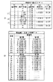
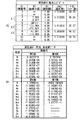
図2(A),図2(B)は、図1に示した画像読取用レンズ1の構成に対応する具体的なレンズデータ(実施例1)を示している。特に図2(A)にはその基本的なレンズデータを示し、図2(B)には、回折、非球面に関するデータを示す。同様に、図3(A),図3(B)には実施例2に係る画像読取用レンズのレンズデータを示し、図4(A),図4(B)には実施例3に係る画像読取用レンズのレンズデータを示し、図5(A),図5(B)には実施例4に係る画像読取用レンズのレンズデータを示し、図6(A),図6(B)には実施例5に係る画像読取用レンズのレンズデータを示す。なお、実施例2〜5に係る画像読取用レンズの基本的なレンズ構成は、図1に示した画像読取用レンズ1と概略同様である。
FIGS. 2A and 2B show specific lens data (Example 1) corresponding to the configuration of the
図2(A),図3(A),図4(A),図5(A),図6(A)に示したレンズデータにおける面番号Siの欄には、各実施例に係る画像読取用レンズについて、光学部材11,12および絞りStも含めて最も物体側の構成要素の面を1番目として、像側に向かうに従い順次増加するようにして符号を付したi番目(i=1〜11)の面の番号を示している。曲率半径Riの欄には、図1において付した符号Riに対応させて、物体側からi番目の面の曲率半径の値を示す。面間隔diの欄についても、同様に物体側からi番目の面Siとi+1番目の面Si+1との光軸上の間隔を示す。曲率半径Riおよび面間隔diの値の単位はミリメートル(mm)である。nejの欄には、物体側からj番目(j=1〜5)の光学要素のe線(波長546.07nm)に対する屈折率の値を示す。νdjの欄には、物体側からj番目の光学要素のd線(波長587.6nm)におけるアッベ数の値を示す。
In the column of the surface number Si in the lens data shown in FIGS. 2A, 3A, 4A, 5A, and 6A, image reading according to each embodiment is performed. For the lens for use, the i-th (i = 1 to 1) is assigned such that the surfaces of the constituent elements closest to the object side including the
各実施例に係る画像読取用レンズは、第1レンズL1の両面S3,S4と第2レンズL2の両面S6,S7とが非球面形状となっている。また、第2レンズL2の物体側の面S6が回折レンズ面となっている。図2(A),図3(A),図4(A),図5(A),図6(A)の基本レンズデータには、これらの非球面の曲率半径として、光軸近傍の曲率半径の数値を示している。 In the image reading lens according to each example, both surfaces S3 and S4 of the first lens L1 and both surfaces S6 and S7 of the second lens L2 are aspherical. The object side surface S6 of the second lens L2 is a diffractive lens surface. The basic lens data in FIGS. 2A, 3A, 4A, 5A, and 6A includes the curvature near the optical axis as the radius of curvature of these aspheric surfaces. The numerical value of the radius is shown.
図2(B),図3(B),図4(B),図5(B),図6(B)には各実施例に係る画像読取用レンズにおける回折および非球面データを示す。非球面データとして示した数値において、記号“E”は、その次に続く数値が10を底とした“べき指数”であることを示し、その10を底とした指数関数で表される数値が“E”の前の数値に乗算されることを示す。例えば、「1.0E−02」であれば、「1.0×10⁻²」であることを示す。 2B, FIG. 3B, FIG. 4B, FIG. 5B, and FIG. 6B show diffraction and aspheric data in the image reading lens according to each example. In the numerical values shown as aspherical data, the symbol “E” indicates that the subsequent numerical value is a “power exponent” with a base of 10, and the numerical value represented by an exponential function with the base of 10 is Indicates that the value before “E” is multiplied. For example, “1.0E-02” indicates “1.0 × 10 −2 ”.
非球面データとしては、以下の式(A)によって表される非球面形状の式における各係数Ai,Kの値を記す。Zは、より詳しくは、光軸から高さhの位置にある非球面上の点から、非球面の頂点の接平面(光軸に垂直な平面)に下ろした垂線の長さ(mm)を示す。
Z=C・h2/{1+(1−K・C2・h2)1/2}+A4・h4+A6・h6+A8・h8+A10・h10+A12・h12+A14・h14+A16・h16 ……(A)
ただし、
Z:非球面の深さ(mm)
h:光軸からレンズ面までの距離(高さ)(mm)
K:円錐定数
C:近軸曲率=1/R
(R:近軸曲率半径)
Ai:第i次の非球面係数(i=4,6,8,10,12,14,16)
As the aspheric surface data, the values of the coefficients A i and K in the aspheric surface expression represented by the following expression (A) are described. More specifically, Z is the length (mm) of a perpendicular line drawn from a point on the aspheric surface at a height h from the optical axis to the tangential plane (plane perpendicular to the optical axis) of the apex of the aspheric surface. Show.
Z = C · h 2 / {1+ (1−K · C 2 · h 2 ) 1/2 } + A 4 · h 4 + A 6 · h 6 + A 8 · h 8 + A 10 · h 10 + A 12 · h 12 + A 14・ h 14 + A 16・ h 16 …… (A)
However,
Z: Depth of aspheric surface (mm)
h: Distance from the optical axis to the lens surface (height) (mm)
K: Conic constant C: Paraxial curvature = 1 / R
(R: paraxial radius of curvature)
A i : i-th aspherical coefficient (i = 4, 6, 8, 10, 12, 14, 16)
また回折レンズ面のデータとしては、以下の式(B)によって表される位相差関数Φにおける第i次の係数Di(i=2,4,6,8,10)の値を記す。
Φ=D2・h2+D4・h4+D6・h6+D8・h8+D10・h10 ……(B)
Further, as the data of the diffractive lens surface, the value of the i-th order coefficient D i (i = 2, 4, 6, 8, 10) in the phase difference function Φ expressed by the following equation (B) is described.
Φ = D 2 · h 2 + D 4 · h 4 + D 6 · h 6 + D 8 · h 8 + D 10 · h 10 ...... (B)
図7には、上述の各条件式に関する値を、各実施例についてまとめたものを示す。図7から分かるように、各実施例の値が、各条件式の数値範囲内となっている。 FIG. 7 shows a summary of the values for the above-described conditional expressions for each example. As can be seen from FIG. 7, the value of each example is within the numerical range of each conditional expression.
図8(A)〜図8(D)はそれぞれ、実施例1に係る画像読取用レンズにおける常温時での球面収差、非点収差、ディストーション(歪曲収差)、および倍率色収差を示している。図9(A)〜図9(D)は、高温時(常温+20°C)における同様の各収差を示している。各収差図には、e線を基準波長とした収差を示すが、球面収差図、非点収差図および倍率色収差図には、g線(波長435.8nm),C線(波長656.3nm),s線(波長852.11nm)についての収差も示す。非点収差図において、実線はサジタル方向、破線はタンジェンシャル方向の収差を示す。FNO.はF値、ωは半画角を示す。 FIGS. 8A to 8D respectively show spherical aberration, astigmatism, distortion (distortion aberration), and lateral chromatic aberration in the image reading lens according to Example 1 at normal temperature. FIGS. 9A to 9D show similar aberrations at a high temperature (normal temperature + 20 ° C.). Each aberration diagram shows an aberration with the e-line as a reference wavelength, but in the spherical aberration diagram, astigmatism diagram and lateral chromatic aberration diagram, the g-line (wavelength 435.8 nm), C-line (wavelength 656.3 nm). , Aberrations for the s-line (wavelength 852.11 nm) are also shown. In the astigmatism diagram, the solid line indicates the sagittal direction and the broken line indicates the tangential direction. FNO. Indicates an F value, and ω indicates a half angle of view.
同様に、実施例2についての常温時での諸収差を図10(A)〜図10(D)、高温時での諸収差を図11(A)〜図11(D)に示す。同様に、実施例3についての常温時での諸収差を図12(A)〜図12(D)、高温時での諸収差を図13(A)〜図13(D)に示す。同様に、実施例4についての常温時での諸収差を図14(A)〜図14(D)、高温時での諸収差を図15(A)〜図15(D)に示す。同様に、実施例5についての常温時での諸収差を図16(A)〜図16(D)、高温時での諸収差を図17(A)〜図17(D)に示す。 Similarly, various aberrations at normal temperature for Example 2 are shown in FIGS. 10A to 10D, and various aberrations at high temperature are shown in FIGS. 11A to 11D. Similarly, FIGS. 12A to 12D show various aberrations of Example 3 at normal temperature, and FIGS. 13A to 13D show various aberrations at high temperature. Similarly, FIGS. 14A to 14D show various aberrations at room temperature for Example 4, and FIGS. 15A to 15D show various aberrations at high temperature. Similarly, FIGS. 16A to 16D show various aberrations of Example 5 at normal temperature, and FIGS. 17A to 17D show various aberrations at high temperature.
以上の各数値データおよび各収差図から分かるように、各実施例について、回折レンズ面を有効に用いることで、諸収差が良好に補正され、半画角で23°以上の広画角化が実現できている。特に軸上色収差と倍率色収差とが同時に良好に補正できている。また、温度変化時の収差変動も抑えられている。 As can be seen from the numerical data and aberration diagrams described above, in each example, by effectively using the diffractive lens surface, various aberrations are corrected well, and a wide field angle of 23 ° or more is achieved with a half field angle. It has been realized. In particular, axial chromatic aberration and lateral chromatic aberration can be corrected well at the same time. In addition, aberration fluctuation at the time of temperature change is also suppressed.
なお、本発明は、上記実施の形態および各実施例に限定されず種々の変形実施が可能である。例えば、各レンズ成分の曲率半径、面間隔および屈折率の値などは、上記各数値実施例で示した値に限定されず、他の値をとり得る。 In addition, this invention is not limited to the said embodiment and each Example, A various deformation | transformation implementation is possible. For example, the radius of curvature, the surface interval, and the refractive index of each lens component are not limited to the values shown in the above numerical examples, and may take other values.
1…画像読取用レンズ、10…画像読取装置、11,12…光学部材、L1…第1レンズ、L2…第2レンズ、L3…第3レンズ、St…絞り、Ri…物体側から第i番目のレンズ面の曲率半径、di…物体側から第i番目と第i+1番目のレンズ面との面間隔、Z1…光軸。
DESCRIPTION OF
Claims (7)
前記第2レンズの物体側の面に回折レンズ面が形成され、
さらに以下の条件を満足するように構成されている
0.012<L/f<0.04 ……(5)
ことを特徴とする画像読取用レンズ。
ただし、
L:最外画角最外光線が第2レンズを通過する光路長
f:全系の焦点距離
とする。 In order from the object side, a first lens composed of a positive meniscus lens having a convex surface facing the object side, a second lens composed of a negative meniscus lens having a concave surface facing the object side, and a positive lens having a convex surface directed to the image side A third lens comprising a lens is disposed,
A diffractive lens surface is formed on the object side surface of the second lens ,
Furthermore, it is configured to satisfy the following conditions:
0.012 <L / f <0.04 (5)
An image reading lens.
However,
L: the optical path length through which the outermost ray of the outermost field angle passes through the second lens
f: Focal length of the entire system
And
ことを特徴とする請求項1に記載の画像読取用レンズ。
3.6<|f12/f3|<6.4 ……(1)
M/D<3.0 ……(2)
(ν1+ν3)/2−ν2>21 ……(3)
ただし、
f12:第1レンズと第2レンズの合成焦点距離
f3:第3レンズの焦点距離
M:回折レンズ面の輪帯数
D:回折レンズ面の有効径(mm)
νi:第iレンズの分散
とする。 The image reading lens according to claim 1, further configured to satisfy the following condition.
3.6 <| f12 / f3 | <6.4 (1)
M / D <3.0 (2)
(Ν1 + ν3) / 2−ν2> 21 (3)
However,
f12: Composite focal length of the first lens and the second lens f3: Focal length of the third lens M: Number of ring zones of the diffractive lens surface D: Effective diameter (mm) of the diffractive lens surface
ν i is the dispersion of the i-th lens.
0.62<|(f2・χ1)/(f1・χ2)|<0.98 ……(4)
ことを特徴とする請求項1または2に記載の画像読取用レンズ。
ただし、
f1:第1レンズの焦点距離
f2:第2レンズの焦点距離
χi:第iレンズの次式で定義される関数
χi=αi−(1/(ni−1))・(dn/dt)i
αi:第iレンズの線膨張係数
ni:第iレンズのe線の屈折率
(dn/dt)i:第iレンズのe線の屈折率温度係数
とする。 Further, it is configured to satisfy the following condition: 0.62 <| (f2 · χ1) / (f1 · χ2) | <0.98 (4)
The image reading lens according to claim 1, wherein the lens is an image reading lens.
However,
f1: Focal length of the first lens f2: Focal length of the second lens χi: Function defined by the following expression of the i-th lens χi = αi− (1 / (ni−1)) · (dn / dt) i
αi: Linear expansion coefficient of i-th lens ni: Refractive index of e-line of i-th lens (dn / dt) i: Refractive index temperature coefficient of e-line of i-th lens
L/f<0.033 ……(5A)
ことを特徴とする請求項1ないし3のいずれか1項に記載の画像読取用レンズ。
ただし、
L:最外画角最外光線が第2レンズを通過する光路長
f:全系の焦点距離
とする。 Furthermore, it is configured to satisfy the following conditions:
L / f <0.033 (5A)
The image reading lens according to claim 1, wherein the lens is an image reading lens.
However,
L: Optical path length through which the outermost light beam at the outermost field angle passes through the second lens f: The focal length of the entire system.
ことを特徴とする請求項1ないし4のいずれか1項に記載の画像読取用レンズ。 The image reading lens according to any one of claims 1 to 4, further comprising a diaphragm disposed between the first lens and the second lens.
ことを特徴とする請求項1ないし5のいずれか1項に記載の画像読取用レンズ。 The image reading lens according to claim 1, wherein the first lens and the second lens are resin lenses.
Priority Applications (1)
| Application Number | Priority Date | Filing Date | Title |
|---|---|---|---|
| JP2005286429A JP4932208B2 (en) | 2005-09-30 | 2005-09-30 | Image reading lens and image reading apparatus |
Applications Claiming Priority (1)
| Application Number | Priority Date | Filing Date | Title |
|---|---|---|---|
| JP2005286429A JP4932208B2 (en) | 2005-09-30 | 2005-09-30 | Image reading lens and image reading apparatus |
Publications (2)
| Publication Number | Publication Date |
|---|---|
| JP2007094278A JP2007094278A (en) | 2007-04-12 |
| JP4932208B2 true JP4932208B2 (en) | 2012-05-16 |
Family
ID=37980031
Family Applications (1)
| Application Number | Title | Priority Date | Filing Date |
|---|---|---|---|
| JP2005286429A Expired - Fee Related JP4932208B2 (en) | 2005-09-30 | 2005-09-30 | Image reading lens and image reading apparatus |
Country Status (1)
| Country | Link |
|---|---|
| JP (1) | JP4932208B2 (en) |
Cited By (1)
| Publication number | Priority date | Publication date | Assignee | Title |
|---|---|---|---|---|
| CN107728296A (en) * | 2016-08-10 | 2018-02-23 | 光芒光学股份有限公司 | Optical lens |
Families Citing this family (4)
| Publication number | Priority date | Publication date | Assignee | Title |
|---|---|---|---|---|
| JP2009008759A (en) | 2007-06-26 | 2009-01-15 | Fujinon Corp | Color image reading lens and color image reading device |
| CN105242379B (en) * | 2014-06-25 | 2018-04-10 | Kolen株式会社 | Imaging lens system |
| CN107505689B (en) * | 2017-09-15 | 2023-08-04 | 江西联创电子有限公司 | Projection lens system |
| TWI757732B (en) | 2020-05-05 | 2022-03-11 | 大立光電股份有限公司 | Image capturing optical lens assembly, imaging apparatus and electronic device |
Family Cites Families (5)
| Publication number | Priority date | Publication date | Assignee | Title |
|---|---|---|---|---|
| JPH10186223A (en) * | 1996-10-24 | 1998-07-14 | Asahi Optical Co Ltd | Triplet lens |
| JPH10311946A (en) * | 1997-05-12 | 1998-11-24 | Olympus Optical Co Ltd | Triplet lens |
| JP3335295B2 (en) * | 1997-07-31 | 2002-10-15 | 旭光学工業株式会社 | Reading lens |
| JP2003295052A (en) * | 2002-03-29 | 2003-10-15 | Fuji Photo Optical Co Ltd | Infrared lens |
| JP2005164773A (en) * | 2003-12-01 | 2005-06-23 | Canon Inc | Diffraction optical element and lens for projection using the same |
-
2005
- 2005-09-30 JP JP2005286429A patent/JP4932208B2/en not_active Expired - Fee Related
Cited By (1)
| Publication number | Priority date | Publication date | Assignee | Title |
|---|---|---|---|---|
| CN107728296A (en) * | 2016-08-10 | 2018-02-23 | 光芒光学股份有限公司 | Optical lens |
Also Published As
| Publication number | Publication date |
|---|---|
| JP2007094278A (en) | 2007-04-12 |
Similar Documents
| Publication | Publication Date | Title |
|---|---|---|
| JP6709564B2 (en) | Imaging lens | |
| JP6699949B2 (en) | Imaging lens | |
| JP6726916B2 (en) | Imaging lens | |
| JP5095443B2 (en) | Image reading lens and image reading apparatus | |
| JP4879600B2 (en) | Imaging lens | |
| JP4963187B2 (en) | Imaging lens and imaging apparatus | |
| JP4965199B2 (en) | Imaging lens | |
| JP6566492B2 (en) | Imaging lens | |
| JP6710473B2 (en) | Imaging lens | |
| JP7319049B2 (en) | imaging lens | |
| JP7481950B2 (en) | Imaging lens | |
| JP7396788B2 (en) | imaging lens | |
| JP7112894B2 (en) | imaging lens | |
| JP7449075B2 (en) | imaging lens | |
| JP7149095B2 (en) | imaging lens | |
| EP1860476B1 (en) | Imaging lens | |
| JP2007086485A (en) | Imaging lens | |
| JP5571255B2 (en) | Objective optical system and endoscope apparatus using the same | |
| JP7409955B2 (en) | imaging lens | |
| JP6587293B2 (en) | Imaging lens | |
| JP4738879B2 (en) | Image reading lens and image reading apparatus | |
| JP7621098B2 (en) | Imaging lens | |
| JP7616793B2 (en) | Imaging lens | |
| JP2006343552A (en) | Zoom lens and imaging apparatus having the same | |
| JP4932208B2 (en) | Image reading lens and image reading apparatus |
Legal Events
| Date | Code | Title | Description |
|---|---|---|---|
| A621 | Written request for application examination |
Free format text: JAPANESE INTERMEDIATE CODE: A621 Effective date: 20080611 |
|
| A711 | Notification of change in applicant |
Free format text: JAPANESE INTERMEDIATE CODE: A711 Effective date: 20100617 |
|
| A977 | Report on retrieval |
Free format text: JAPANESE INTERMEDIATE CODE: A971007 Effective date: 20110523 |
|
| A131 | Notification of reasons for refusal |
Free format text: JAPANESE INTERMEDIATE CODE: A131 Effective date: 20110816 |
|
| A521 | Written amendment |
Free format text: JAPANESE INTERMEDIATE CODE: A523 Effective date: 20111013 |
|
| TRDD | Decision of grant or rejection written | ||
| A01 | Written decision to grant a patent or to grant a registration (utility model) |
Free format text: JAPANESE INTERMEDIATE CODE: A01 Effective date: 20120214 |
|
| A01 | Written decision to grant a patent or to grant a registration (utility model) |
Free format text: JAPANESE INTERMEDIATE CODE: A01 |
|
| A61 | First payment of annual fees (during grant procedure) |
Free format text: JAPANESE INTERMEDIATE CODE: A61 Effective date: 20120215 |
|
| R150 | Certificate of patent or registration of utility model |
Free format text: JAPANESE INTERMEDIATE CODE: R150 |
|
| FPAY | Renewal fee payment (event date is renewal date of database) |
Free format text: PAYMENT UNTIL: 20150224 Year of fee payment: 3 |
|
| R250 | Receipt of annual fees |
Free format text: JAPANESE INTERMEDIATE CODE: R250 |
|
| R250 | Receipt of annual fees |
Free format text: JAPANESE INTERMEDIATE CODE: R250 |
|
| R250 | Receipt of annual fees |
Free format text: JAPANESE INTERMEDIATE CODE: R250 |
|
| LAPS | Cancellation because of no payment of annual fees |