EP1692465B1 - Magnetic inductive flowmeter and method for the production thereof - Google Patents
Magnetic inductive flowmeter and method for the production thereof Download PDFInfo
- Publication number
- EP1692465B1 EP1692465B1 EP04804658A EP04804658A EP1692465B1 EP 1692465 B1 EP1692465 B1 EP 1692465B1 EP 04804658 A EP04804658 A EP 04804658A EP 04804658 A EP04804658 A EP 04804658A EP 1692465 B1 EP1692465 B1 EP 1692465B1
- Authority
- EP
- European Patent Office
- Prior art keywords
- liner
- carrier tube
- tube
- support body
- groove
- Prior art date
- Legal status (The legal status is an assumption and is not a legal conclusion. Google has not performed a legal analysis and makes no representation as to the accuracy of the status listed.)
- Expired - Lifetime
Links
- 230000005291 magnetic effect Effects 0.000 title claims abstract description 21
- 238000000034 method Methods 0.000 title claims description 20
- 238000004519 manufacturing process Methods 0.000 title claims description 13
- 230000001939 inductive effect Effects 0.000 title 1
- 239000011810 insulating material Substances 0.000 claims abstract description 37
- 239000012530 fluid Substances 0.000 claims abstract description 36
- 239000000463 material Substances 0.000 claims abstract description 25
- 230000005684 electric field Effects 0.000 claims abstract description 10
- 238000005245 sintering Methods 0.000 claims description 35
- 239000011148 porous material Substances 0.000 claims description 4
- 230000000087 stabilizing effect Effects 0.000 claims description 3
- 238000010079 rubber tapping Methods 0.000 abstract description 5
- 230000006641 stabilisation Effects 0.000 abstract description 4
- 238000011105 stabilization Methods 0.000 abstract description 4
- 238000001816 cooling Methods 0.000 abstract description 3
- 238000006073 displacement reaction Methods 0.000 abstract description 3
- 230000015572 biosynthetic process Effects 0.000 abstract description 2
- 238000005266 casting Methods 0.000 description 16
- 238000011049 filling Methods 0.000 description 13
- 239000007858 starting material Substances 0.000 description 13
- 238000003780 insertion Methods 0.000 description 8
- 230000037431 insertion Effects 0.000 description 8
- 238000007711 solidification Methods 0.000 description 7
- 230000008023 solidification Effects 0.000 description 7
- 239000002245 particle Substances 0.000 description 6
- 238000011161 development Methods 0.000 description 5
- 230000005294 ferromagnetic effect Effects 0.000 description 4
- 239000002184 metal Substances 0.000 description 4
- 229910052751 metal Inorganic materials 0.000 description 4
- 239000004033 plastic Substances 0.000 description 4
- 229920003023 plastic Polymers 0.000 description 4
- 229920001169 thermoplastic Polymers 0.000 description 4
- 239000004416 thermosoftening plastic Substances 0.000 description 4
- 230000006978 adaptation Effects 0.000 description 3
- 238000011156 evaluation Methods 0.000 description 3
- 238000009434 installation Methods 0.000 description 3
- 229910001220 stainless steel Inorganic materials 0.000 description 3
- 229920001187 thermosetting polymer Polymers 0.000 description 3
- 229910045601 alloy Inorganic materials 0.000 description 2
- 239000000956 alloy Substances 0.000 description 2
- 238000005452 bending Methods 0.000 description 2
- 239000000919 ceramic Substances 0.000 description 2
- 238000005336 cracking Methods 0.000 description 2
- 239000003302 ferromagnetic material Substances 0.000 description 2
- -1 for example Inorganic materials 0.000 description 2
- 239000011521 glass Substances 0.000 description 2
- 238000011065 in-situ storage Methods 0.000 description 2
- 238000001746 injection moulding Methods 0.000 description 2
- 230000007774 longterm Effects 0.000 description 2
- 238000007789 sealing Methods 0.000 description 2
- 229910000906 Bronze Inorganic materials 0.000 description 1
- 229910000881 Cu alloy Inorganic materials 0.000 description 1
- YCKRFDGAMUMZLT-UHFFFAOYSA-N Fluorine atom Chemical compound [F] YCKRFDGAMUMZLT-UHFFFAOYSA-N 0.000 description 1
- 229910000990 Ni alloy Inorganic materials 0.000 description 1
- 229910001069 Ti alloy Inorganic materials 0.000 description 1
- 230000002411 adverse Effects 0.000 description 1
- 239000010974 bronze Substances 0.000 description 1
- 239000002800 charge carrier Substances 0.000 description 1
- 238000007906 compression Methods 0.000 description 1
- 230000006835 compression Effects 0.000 description 1
- KUNSUQLRTQLHQQ-UHFFFAOYSA-N copper tin Chemical compound [Cu].[Sn] KUNSUQLRTQLHQQ-UHFFFAOYSA-N 0.000 description 1
- 230000008878 coupling Effects 0.000 description 1
- 238000010168 coupling process Methods 0.000 description 1
- 238000005859 coupling reaction Methods 0.000 description 1
- 238000005520 cutting process Methods 0.000 description 1
- 230000006378 damage Effects 0.000 description 1
- 238000013461 design Methods 0.000 description 1
- 238000005553 drilling Methods 0.000 description 1
- 238000010292 electrical insulation Methods 0.000 description 1
- 230000001747 exhibiting effect Effects 0.000 description 1
- 239000011152 fibreglass Substances 0.000 description 1
- 229910052731 fluorine Inorganic materials 0.000 description 1
- 239000011737 fluorine Substances 0.000 description 1
- 238000011835 investigation Methods 0.000 description 1
- 239000007788 liquid Substances 0.000 description 1
- 238000003754 machining Methods 0.000 description 1
- 238000005259 measurement Methods 0.000 description 1
- 238000002844 melting Methods 0.000 description 1
- 230000008018 melting Effects 0.000 description 1
- 239000002923 metal particle Substances 0.000 description 1
- 238000003801 milling Methods 0.000 description 1
- 239000000203 mixture Substances 0.000 description 1
- 238000012544 monitoring process Methods 0.000 description 1
- 239000002985 plastic film Substances 0.000 description 1
- 229920006255 plastic film Polymers 0.000 description 1
- 229920000098 polyolefin Polymers 0.000 description 1
- 229920002635 polyurethane Polymers 0.000 description 1
- 239000004814 polyurethane Substances 0.000 description 1
- 238000002360 preparation method Methods 0.000 description 1
- 238000012545 processing Methods 0.000 description 1
- 238000001953 recrystallisation Methods 0.000 description 1
- 239000011347 resin Substances 0.000 description 1
- 229920005989 resin Polymers 0.000 description 1
- 238000007493 shaping process Methods 0.000 description 1
- 238000002791 soaking Methods 0.000 description 1
- 239000010935 stainless steel Substances 0.000 description 1
- 239000000126 substance Substances 0.000 description 1
- 230000001629 suppression Effects 0.000 description 1
- 238000012546 transfer Methods 0.000 description 1
- 238000001721 transfer moulding Methods 0.000 description 1
Images


Classifications
-
- G—PHYSICS
- G01—MEASURING; TESTING
- G01F—MEASURING VOLUME, VOLUME FLOW, MASS FLOW OR LIQUID LEVEL; METERING BY VOLUME
- G01F1/00—Measuring the volume flow or mass flow of fluid or fluent solid material wherein the fluid passes through a meter in a continuous flow
- G01F1/56—Measuring the volume flow or mass flow of fluid or fluent solid material wherein the fluid passes through a meter in a continuous flow by using electric or magnetic effects
- G01F1/58—Measuring the volume flow or mass flow of fluid or fluent solid material wherein the fluid passes through a meter in a continuous flow by using electric or magnetic effects by electromagnetic flowmeters
- G01F1/584—Measuring the volume flow or mass flow of fluid or fluent solid material wherein the fluid passes through a meter in a continuous flow by using electric or magnetic effects by electromagnetic flowmeters constructions of electrodes, accessories therefor
-
- G—PHYSICS
- G01—MEASURING; TESTING
- G01F—MEASURING VOLUME, VOLUME FLOW, MASS FLOW OR LIQUID LEVEL; METERING BY VOLUME
- G01F1/00—Measuring the volume flow or mass flow of fluid or fluent solid material wherein the fluid passes through a meter in a continuous flow
- G01F1/56—Measuring the volume flow or mass flow of fluid or fluent solid material wherein the fluid passes through a meter in a continuous flow by using electric or magnetic effects
- G01F1/58—Measuring the volume flow or mass flow of fluid or fluent solid material wherein the fluid passes through a meter in a continuous flow by using electric or magnetic effects by electromagnetic flowmeters
- G01F1/588—Measuring the volume flow or mass flow of fluid or fluent solid material wherein the fluid passes through a meter in a continuous flow by using electric or magnetic effects by electromagnetic flowmeters combined constructions of electrodes, coils or magnetic circuits, accessories therefor
-
- G—PHYSICS
- G01—MEASURING; TESTING
- G01F—MEASURING VOLUME, VOLUME FLOW, MASS FLOW OR LIQUID LEVEL; METERING BY VOLUME
- G01F15/00—Details of, or accessories for, apparatus of groups G01F1/00 - G01F13/00 insofar as such details or appliances are not adapted to particular types of such apparatus
- G01F15/18—Supports or connecting means for meters
-
- Y—GENERAL TAGGING OF NEW TECHNOLOGICAL DEVELOPMENTS; GENERAL TAGGING OF CROSS-SECTIONAL TECHNOLOGIES SPANNING OVER SEVERAL SECTIONS OF THE IPC; TECHNICAL SUBJECTS COVERED BY FORMER USPC CROSS-REFERENCE ART COLLECTIONS [XRACs] AND DIGESTS
- Y10—TECHNICAL SUBJECTS COVERED BY FORMER USPC
- Y10T—TECHNICAL SUBJECTS COVERED BY FORMER US CLASSIFICATION
- Y10T29/00—Metal working
- Y10T29/49—Method of mechanical manufacture
- Y10T29/49002—Electrical device making
- Y10T29/4902—Electromagnet, transformer or inductor
Definitions
- the invention relates to a method for producing a magnetic-inductive Human Fluorescence (Functional) of the invention.
- a magnetic-inductive flow sensor By means of a magnetic-inductive flow sensor, it is known to measure the volume flow rate of an electrically conductive fluid through which flows a measuring tube of this flow sensor in a flow direction.
- a magnetic field of the highest possible density is generated at the für fluorescence (PLC) means of a coupled to an exciter electronics magnetic circuit, which passes through the fluid within a measuring volume at least partially perpendicular to the flow direction and which closes substantially outside of the fluid.
- the measuring tube is therefore usually made of non-ferromagnetic material, so that the magnetic field is not adversely affected during measurement.
- an electric field is generated according to the magneto-hydrodynamic principle in the measuring volume, which is perpendicular to the magnetic field and perpendicular to the flow direction of the fluid.
- the fluid-contacting, galvanic or the fluid non-contacting, capacitive measuring electrodes can serve.
- the magnetic circuit arrangement For guiding and coupling the magnetic field into the measuring volume, the magnetic circuit arrangement usually comprises two coil cores, which are in particular diametrically spaced from each other along a circumference of the measuring tube and are each arranged with a free end-side end face, in particular a mirror image.
- the magnetic field is coupled into the coil cores by means of a coil arrangement connected to the exciter electronics such that it passes through the fluid flowing between the two end faces at least in sections perpendicular to the flow direction.
- a magneto-inductive flow sensor which comprises:
- non-ferromagnetic carrier tube as an outer envelope of the measuring tube
- a tubular liner housed in a lumen of the support tube and made of an insulating material for guiding a fluid flowing and isolated from the support tube
- the liner serves to chemically isolate the carrier tube from the fluid.
- the liner In support tubes of high electrical conductivity, esp. In metallic support tubes, the liner also serves as electrical insulation between the support tube and the fluid, which prevents shorting of the electric field via the support tube.
- Injection molding or transfer molding processes are often used to manufacture the liner.
- thermoplastic or thermosetting plastic liner is used to stabilize it, such as in the EP-A 36 513 , of the EP-A 581 017 , of the JP-Y 53 - 51 181 , of the JP-A 59-133722 , of the US-B 65 95 069 , of the US Pat. No. 5,664,315 , of the US-A 5,280,727 or the US-A 4,329,879 shown, usually porous, esp. Metallic, embedded support body. This serves the liner, esp. against pressure changes and thermally induced volume changes, mechanically stabilize.
- a thermoplastic or thermosetting plastic liner is used to stabilize it, such as in the EP-A 36 513 , of the EP-A 581 017 , of the JP-Y 53 - 51 181 , of the JP-A 59-133722 , of the US-B 65 95 069 , of the US Pat. No. 5,664,315 , of the US-A 5,280,727 or the US
- 5,664,315 is a method for producing a measuring tube of a magnetic-inductive Naturalflußauf choirs having a liner inside, described in which prior to the introduction of the liner in the support tube, a liner mechanically stabilizing expanded metal mesh is attached as a prefabricated support body. Furthermore, in the JP-Y 53-51181 a tubular support body shown in the lateral surfaces bores are introduced while in the EP-A 581 017 or the US-B 65 95 069 sintered support body are shown. The support bodies are introduced in the measuring tube with this aligned and completely enclosed by the insulating material at least on the fluid contacting inside.
- a method for producing a liner with embedded support body shown in the support body and liner are made directly in the lumen of the support tube, the support body are first formed by sintering in the carrier and the liner by solidification of the carrier tube then filled liquid insulating material.
- Example is in the US-B 65 95 069 It has also been shown that the supporting body is in each case widening on its end in such a way that it fits into correspondingly corresponding end-side funnel-shaped widenings in the carrier tube and is thereby axially fixed. Moreover, in the US-B 65 95 069 shown a support body, the middle of the carrier tube introduced lateral jacket openings completely or partially fills and so takes place an additional locking of the support body in the support tube.
- liners of the type described have a very high mechanical long-term stability in operation, even in temperature ranges from -40 ° C to 200 ° C.
- this high long-term stability is very closely linked to an extremely high quality especially of the support body.
- An object of the invention is to provide a magnetic-inductive flow sensor and a suitable method for producing such a flow sensor, in which flow sensor on the one hand, the inclination of the liner and / or the possibly existing support body to cracking with temperature changes, inbs. on cooling, significantly reduced and on the other hand, a rotation or displacement of the support body in the support tube can be effectively prevented even in case of material shrinkage.
- the invention consists in a magnetic-inductive Sirickersacrificing for a flowing fluid in a pipeline, comprising the features of claim 1.
- the invention in a method according to claim 8 for producing the measuring tube for the aforementioned erfmdungshacken fürflußaufillon, which method comprises the steps manufacturing the support body in the lumen of the support tube and introducing the liner into the lumen of the support tube.
- loose sintered starting material is filled into the lumen of the support tube so as to at least partially fill the at least one groove, and the filled sintered starting material is sintered inside the support tube.
- insulating material will at least partially penetrate into the fabricated support body and be allowed to solidify in the lumen of the support tube.
- the measuring tube for stabilizing the liner further comprises an embedded in the liner open-pored support body and is the at least one, esp. Having an undercut, groove of a, esp. Sintered, material of, esp Support body sintered in the support tube, at least partially filled so that the support body is positively connected to the support tube.
- the at least one, esp. Having an undercut groove of the insulating material of the liner is at least partially filled so that the liner is positively connected to the support tube.
- the at least one groove on an undercut which is so filled by the insulating material of the liner, that between the liner and the carrier tube an at least radially inwardly effective positive engagement is formed.
- the groove has a substantially trapezoidal cross-section.
- the support tube made of non-ferromagnetic material, esp. Made of stainless steel.
- the support body made of sintered metal, sintered ceramic and / or sintered glass.
- the liner made of plastic, esp. Thermoplastics or thermosets.
- the at least one groove on an undercut which is so filled with the material of the support body, that between the support body and support tube a radially inwardly effective positive engagement is formed.
- the supporting body is formed with a correspondingly corresponding to the first groove, at least partially from the material of the support body existing and projecting into the first groove web.
- the sintered starting material is filled into a sintering space for producing the support body, which is formed in the lumen of the support tube by means of at least one sintering dome inserted therein.
- the insulating material is liquefied and filled in a casting space, which is formed in the lumen of the support tube by means of at least one casting mandrel inserted therein.
- a basic idea of the invention consists of an additional, in particular radially inwardly and axially acting, positive connection of the liner and / or the Support body with the support tube on the one hand in the support body and / or in the liner to minimize maximum bending moments or bending stresses and so to keep the tendency to crack formation in the support body and / or liner very low.
- twisting or tilting of the support body in the support tube, esp. Before or during the manufacture of the liner can be effectively avoided by a positive connection of the support body with the support tube.
- Fig. 1 shows in perspective in longitudinal section a magnetic-inductive flow sensor
- Fig. 2 shows in cross-section a substantial part of a magnetic-inductive flow sensor
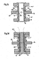
- Fig. 3a shows in longitudinal section a carrier tube with jacket openings for the insertion of coil cores and measuring electrodes
- Fig. 3b shows in longitudinal section the filling of sintered material in the support tube of Fig. 3a .
- Fig. 3c shows in longitudinal section the support tube of Fig. 3a with a support body and with coil cores sintered therein,
- Fig. 3d shows in longitudinal section the filling of further sintered material in the support tube of Fig. 3c .
- Fig. 3e shows in longitudinal section the filling of insulating material in the support tube Fig. 3c and
- Fig. 3f shows in longitudinal section a magnetic-inductive flow sensor.
- Fig. 1 shows in perspective in longitudinal section a magnetic-inductive flow sensor and Fig. 2 shows schematically in cross section a substantial part of the fürflußaufitess.
- the fürflußaufsacrificing comprises a straight measuring tube 1 of predeterminable shape and size for guiding a flowing fluid, arranged on a measuring tube 1 magnetic circuit arrangement 2 for guiding a magnetic field through the fluid and also arranged on the measuring tube 1 Meßelektrodenan extract 3 for measuring a voltage induced in the fluid.
- the measuring tube 1 For pressure-tight insertion into a pipe through which a fluid can flow, the measuring tube 1 has a first flange at an inlet-side first end and a second flange at an outlet-side second end.
- the measuring tube 1 comprises a carrier tube 11 of predeterminable lumen and a tubular, consisting of an insulating liner 12 of predeterminable width and an embedded in the liner 12, open-pored support body 13 of predeterminable pore size and thickness.
- the likewise tubular support body 13 is used for mechanical stabilization of the liner 12, esp. At temperatures of the flowing fluid from -40 ° C to 200 ° in a pressure range of 0 bar to 40 bar.
- the support tube 11 surrounds the liner 12 with embedded support body 13 coaxially and thus serves as an outer shaping and shape-stabilizing enclosure measuring tube 1.
- the measuring tube 1 is designed so that the supporting body 13 is completely covered by the liner 12 on its inner side in contact with the fluid, and thus alone the liner 12 is wetted by the fluid flowing through the measuring tube 1, cf. this also the US-A 32 13 685 ; if necessary, the carrier tube 11 itself can be contacted internally by the material of the liner, especially also completely lined.
- the flow sensor is positioned after the Fig. 1 and 2 a magnetic circuit arrangement 2.
- This comprises a first and a second cylindrical coil 21, 22, each of which surrounds a first and a second ferromagnetic coil core 23, 24 each having a free end-side first and second end face 232, 242 of predeterminable shape.
- the coil cores are preferably designed as a single sheet metal part or as a package of several, electrically isolated from each other layered sheet metal parts, see.
- the coil cores 23, 24 are connected at their respective end face 232 and 242 opposite ends with a not shown, also ferromagnetic, inference of predeterminable length and shape.
- the return is placed on both sides of the outside of the measuring tube 1, see. this the US-A 46 41 537 ,
- the coils 21, 22 are each wound on a tubular, the respective coil core 23, 24 coaxially enclosing first and second bobbin 25, 26; However, the coils 21, 22 can also be self-supporting or at least partially embedded in the bobbin 25, 26. In addition to magnetic circuit arrangements with two coils and those with three or more coils are common, see. this the JP-A 3-218,414 , In measuring operation, the coils 21, 22 are connected to an exciter electronics for generating electrical currents of predeterminable amperage and flows through the latter. This results in two partial magnetic fields, which cut the respective end faces 232, 242 of the associated coil cores 23, 24 substantially normal to the surface and thereby superposed directed to a resulting magnetic field. This passes through the fluid flowing within a measuring volume in sections perpendicular to its flow direction. Exciter electronics can be the circuits described in the prior art.
- the measuring tube 1 For receiving the coil cores 23, 24, the measuring tube 1 comprises a first coil core seat 14 for the frontal insertion of the spool core 23 and a second spool core seat 15 for the frontal insertion of the spool core 24, see. the Fig. 1 and 2 ,
- the spool core seat 14, 15 have a respective first end surfaces 231 and 241 of the coil cores 23, 24 positively touching first and second surface on which the respective associated coil core 23, 24 is applied flat.
- the support tube 11 is provided with a lateral first shell opening 113 and with a lateral second shell opening 114. Both shell openings 113, 114 have the same shape and are spaced apart along a circumferential circle of the support tube 11, esp., So that they are diametrically opposed.
- the coil cores 23, 24 are inserted through the respective shell opening 113 and 114 into the measuring tube 1 and aligned with each other so that their two end faces 231, 241 spaced apart along the circumference circle, esp. Diametrically spaced and mirror image, opposite.
- the jacket openings 113, 114 or the end faces 231, 241 can also be spaced apart from one another along a chord of the circumferential circle of the measuring tube 1 and / or be arranged on the measuring tube 1 in a non-mirror-image manner, cf. JP-A 3-218,414 ,
- the shell openings 113, 114 are of course to be dimensioned so that the coil cores 23, 24 readily fit through.
- the measuring tube 1 sensor assembly 3 which comprises a first and a second measuring electrode 31, 32.
- the measuring electrodes are rod-shaped with a first and a second measuring electrode head 311, 321 for tapping the induced voltage mentioned above and with a first and a second measuring electrode shaft 312, 322, the connecting the sensor assembly to an evaluation electronics serves, educates.
- the measuring electrodes 31, 32 can, as in Fig. 2 represented, galvanic or even capacitive measuring electrodes.
- the support tube 11 is therefore further provided with a lateral third and fourth shell opening 115, 116 for the insertion of the measuring electrode 31 and 32, respectively.
- the jacket openings 115, 116 have a width which is greater than a largest diameter of the respective measuring electrode shaft 312 or 322. They preferably have the same shape and are preferably diametrically opposite one another, wherein a diameter of the carrier tube 11 connecting the jacket openings 115, 116 extends perpendicularly to a diameter of the carrier tube 11 connecting the jacket openings 113, 114.
- the support tube 11 further comprises at least one formed in a wall of the support tube, the lumen of the support tube 11 toward open first groove 115, wherein the groove 115 is at least partially filled by the insulating material of the liner 13 and / or the material of the support body 12.
- the support tube 11 further comprises at least one open to the lumen of the support tube second groove 116, which is formed from the first groove 115 spaced in the wall of the support tube 11.
- Both grooves 115, 116 may advantageously be shaped substantially equal to each other. If necessary, of course, further, the stabilization of the liner 12 and the support body 13 serving grooves in the support tube 11 may be provided.
- the at least one groove 115 is at least partially filled by the material of the support body 12 so that the support body 12 is positively connected to the support tube 11, the support body 12 corresponding to the groove 115 corresponding at least partially from the material the support body existing and projecting into the groove web 14 is integrally formed.
- the at least one groove 115 of the insulating material of the liner 13 is at least partially filled so that the liner 13 is positively connected to the support tube 11.
- the at least one groove is at least partially filled both by the insulating material of the liner 13 and the material of the support body 13, wherein the web 14 at least partially consists of the insulating material of the liner 13 and the material of the support body 12.
- the first groove 115 as in FIG Fig. 1 shown, an undercut on.
- the undercut is so filled by the insulating material of the liner 13 that between liner 13 and support tube 11 is a radially inwardly, ie in the direction of the lumen, esp. But a radially and axially, to a longitudinal axis of the measuring tube 1 effective positive engagement and / or the undercut is so filled by the material of the support body 12, that between the support body 12 and the support tube 11 is a radially inwardly, esp. But a radially and axially, to the longitudinal axis of the measuring tube 1 effective positive engagement is formed.
- the groove 115 is formed as a substantially coaxial with the wall of the support tube 11 extending, esp.
- a substantially trapezoidal or dovetail-shaped cross-section having annular groove formed at least in sections of the support body 12 and / or the Liner 13 molded web 14 is filled.
- Fig. 3a to 3f show different process steps of the invention Process for the preparation of the naturalflußauf choirs.
- Fig. 3a is the support tube 11 with the two grooves 115, 116 shown in the wall of the support tube 11 at the beginning of the process.
- the support tube 11 is preferably produced inexpensively as a casting, which is subsequently finished, for example, by machining processes such as milling, turning and / or drilling; Of course, it can also be manufactured exclusively by cutting processes or other manufacturing processes known to those skilled in the art for pipes.
- machining processes such as milling, turning and / or drilling
- Alloyed and high-alloy stainless steels are used; however, it is also possible to use other non-ferromagnetic alloys, such as, for example, copper alloys, titanium alloys or nickel alloys, but also suitable plastics, such as, for example, glass-fiber-reinforced plastics.
- the support body 13 is after Fig. 1 a tubular body which is made in the process of the invention by in-situ sintering of granular sintered starting material of predeterminable particle size, ie by sintering in the final form and installation position, in the carrier tube 11 in a plangeförmig and tightly fitting.
- a first sintered mandrel 411 is introduced into the lumen of the support tube 11 and temporarily fixed there so that a first sintered space 41 running coaxially with the support tube 11 is formed by predeterminable first sintered volume.
- the sintering mandrel 411 consists of two partial domes, which are designed so that they abut each other after introduction into the support tube 11 with their respective end faces;
- the sintering mandrel 411 can also be designed in one piece in a suitable manner.
- the sintering mandrel 411 may also be non-rotationally symmetric, if necessary, e.g. elliptical or prismatic.
- the sintered mandrel 411 consists of two partial domes, which are designed in a corresponding conical or funnel-shaped and after the introduction into the support tube 11 each abut each other with their smaller end faces.
- the support tube 11 After the introduction of the sintering mandrel 411, the support tube 11 is closed so that only fill openings for the sintered starting material remain. These are preferred by a single open end of the support tube eleventh educated.
- the fixing of the sintering mandrel 411 and the closing of the sintering space 41 is usually carried out by means of an end-side first flange 412; becomes the sintering mandrel 411, as in Fig. 3b shown, also fixed at the second end by means of an end-side second flange 413, so preferably one of the two flanges 412, 413, the corresponding filling openings 414 on. It is obvious and clear that particle size, sintering volume and filling openings are to be dimensioned so that the sintered starting material can be filled into the sintering space 41.
- sinter starting material serve metal particles, esp. Of sintered bronze; however, other materials such as e.g. Sintered glass particles, sintered ceramic particles or sinterable, esp. Surface-metallized, plastic particles used.
- the measuring tube 1 is lined inside with a liner 12, in such a way that support body 13 and support tube 11 are completely isolated in the operation of the fürflußaufêts from the fluid flowing therethrough.
- the liner 12 is according to Fig. 3e after manufacture of the support body 13 also made directly in the support tube 11 by filling and solidification of liquefied insulating material. This is preferably done in a conventional transfer, compression or injection molding process.
- all those used in magnetic-inductive Naturalflußaufillonstoffough strictly for the liner 12 plastics serve that can be liquefied at least once for introduction into the support tube 11, such as.
- Thermoplastics in particular fluorine-containing thermoplastics or polyolefins, or thermosets, esp. Cast resins or polyurethanes.
- the sintering mandrel 411 or 421 used in the sintering is replaced by a casting mandrel 511, which is temporarily fixed in the lumen of the support tube 11, that between the casting mandrel 511 and the support body 13 with a the longitudinal axis of the lumen coaxially aligned casting chamber 51 is formed by predetermined casting volume.
- the casting mandrel 511 is preferably cylindrical with a diameter which, taking into account a casting volume shrinkage after solidification, at most equal to the predetermined width of the liner 12 is formed.
- the support tube 11 is pour-proof closed so that only pour openings for the liquefied insulating material remain.
- the fixing of the casting mandrel 511 and the closing of the support tube 11 is usually carried out by means of a third and fourth end-side flange 512 or 513, one of which, for example, has a corresponding pouring opening 514.
- the support tube 11 After closing the support tube 11 liquefied insulating material is filled in the casting chamber 51. This penetrates into the pores of the support body 13 and fills it out; if necessary, the sintered web 14 is also completed with insulating material.
- the filling is preferably carried out until the casting chamber 51 and the support body 13 are completely filled with the insulating material, but at least until the casting chamber 51 is completely and the support body 13 at least partially filled with the insulating material.
- the insulating material completely covers the support body 13 at least at the inner side facing the fluid during operation of the flow sensor.
- the insulating material After filling, the insulating material is solidified and thus the liner 12 with embedded support body 13 in the lumen of the support tube 11 in the form of a passport formed such that it isolates the support body 13 and the support tube 11 from the fluid.
- the carrier tube 11 has a first widening 111 introduced into the inlet-side first end and a second widening 112 introduced into the outlet-side second end.
- the two expansions 111, 112 are after Fig. 1 or 3a sections inwardly tapered tapered; but they can also be of straight cylindrical shape.
- Both widenings 111, 112 are at least partially filled in the sintering of the sintered starting material, in such a way that the sintered support body 13 is clamped to the support tube 11 and thus additionally fixed, see. Fig. 3c ,
- the widenings 111, 112 of the support body 13 are filled so that the liner 12, the support body 13 in the region of the widening 111, 112 partially surrounds and thus practically completely covered at the end, see. this the 3e and 3f ,
- shell openings 113, 114 are introduced and during the filling and sintering of the sintered starting material for the support body 13 by means of a first or by means of a second sintered closure 415, 416 closed in a sinter-tight manner, cf. Fig. 3b ,
- the two sintered closures 415, 416 are designed so that the support body 13 according to Fig. 3c the two shell openings 113, 114 at least partially fills.
- the filling of the shell openings 113, 114 is carried out, for example, so that the support body 13 laterally against the shell openings 113, 114 and is thus additionally locked. If necessary, the two shell openings 113, 114 are filled and solidified by the liquefied insulating material for the liner 12, as in FIG Fig. 3e represented by a first or by means of a second pouring closure 515, 516 to seal pour-tight.
- additional webs and shoulders may be formed in the shell openings 113, 114 during their production, against which the support body 13 or the liner 12 is supported.
- the jacket openings 115, 116 by means of a third, not shown, or by means of a likewise not shown fourth sintering dome after insertion according to another embodiment of the method of the invention of the first sintering dome 411 closed in a sinter-tight manner.
- Closing the sheath openings 115, 116 is preferably carried out so that the third and the fourth mandrel reach to the sintering mandrel 411, whereby after sintering of the support body 13, the two shell openings 115, 116 continue in this consistently, cf. Fig. 2 ,
- the third and fourth mandrel each have a smallest diameter which is at least slightly larger than a largest diameter of the first and second Meßelektroden-Schaftes.
- the shell openings 115, 116 and their extension in the support body for filling the insulating material further preferably with a third or a fourth pour closure closed so that after the solidification of the insulating material, the measuring tube 1, starting from the respective shell opening 115th or 116, a first and a second Meßelektroden pressgangs.
- the pour-tight sealing of the jacket openings 115, 116 can for example be such that the measuring electrode bushings are completely covered on the inside and with a predetermined minimum thickness of the insulating material and thus already during the production of the liner 12 electrically insulated measuring electrode bushings for the subsequent be created to be used measuring electrodes.
- the third or fourth G manverschlußes is, taking into account the G manufactoring, form in a suitable manner so that after the solidification of the insulating already pass-shaped, the Meßelektroden-shafts 312, 322 corresponding Meßelektroden-passages are formed in the measuring tube 1.
- the pouring closures are in particularly advantageously designed so that in this the measuring electrodes 31, 32 can be used so that the latter already arranged in their final installation position in the measuring tube 1 after filling and solidification of the insulating material while the insulating material of the liner 12 against the support body 13 and the carrier tube 11 and in operation against the fluid are completely electrically isolated.
- the measuring electrode shafts 312, 322 are preferably prismatic, esp. Cuboid, executed within the Meßelektroden-implementation preferably at least in sections, whereby the measuring electrodes 31, 32 without a counter tool in the lumen of the measuring tube 1 are easy to install.
- the sintering-tight or pour-proof sealing of the corresponding measuring electrode openings takes place before the sintering of the supporting body or, before the filling of the insulating material in an analogous manner with corresponding castings or sintered closures.
- the softening temperature of the support tube 11 must be greater than that of the support body 13 and the latter in turn must be greater than the melting temperature of the liner 12.
Landscapes
- Physics & Mathematics (AREA)
- Fluid Mechanics (AREA)
- General Physics & Mathematics (AREA)
- Electromagnetism (AREA)
- Measuring Volume Flow (AREA)
Abstract
Description
Die Erfindung betrifft ein Verfahren zum Herstellen eines magnetisch-induktiven Durchflußaufnehmers und einen mittels des Verfahrens entsprechend herstellbaren Durchflußaufnehmer.The invention relates to a method for producing a magnetic-inductive Durchflußaufnehmers and a correspondingly producible by the method Durchflußaufnehmer.
Mittels magnetisch-induktiven Durchflußaufnehmer läßt sich bekanntlich der Volumendurchfluß eines elektrisch leitfähigen Fluids messen, das ein Meßrohr dieses Durchflußaufnehmers in einer Strömungsrichtung durchströmt. Hierzu wird am Durchflußaufnehmer mittels einer an eine Erreger-Elektronik angekoppelten Magnetkreisanordnung ein Magnetfeld von möglichst hoher Dichte erzeugt, das das Fluid innerhalb eines Meßvolumens zumindest abschnittsweise senkrecht zur Strömungsrichtung durchsetzt und das sich im wesentlichen außerhalb des Fluids schließt. Das Meßrohr besteht daher üblicherweise aus nicht-ferromagnetischem Material, damit das Magnetfeld beim Messen nicht ungünstig beeinflußt wird.By means of a magnetic-inductive flow sensor, it is known to measure the volume flow rate of an electrically conductive fluid through which flows a measuring tube of this flow sensor in a flow direction. For this purpose, a magnetic field of the highest possible density is generated at the Durchflußaufnehmer means of a coupled to an exciter electronics magnetic circuit, which passes through the fluid within a measuring volume at least partially perpendicular to the flow direction and which closes substantially outside of the fluid. The measuring tube is therefore usually made of non-ferromagnetic material, so that the magnetic field is not adversely affected during measurement.
Infolge der Bewegung der freien Ladungsträger des Fluids im Magnetfeld wird nach dem magneto-hydrodynamischen Prinzip im Meßvolumen ein elektrisches Feld erzeugt, das senkrecht zum Magnetfeld und senkrecht zur Strömungsrichtung des Fluids verläuft. Mittels wenigstens zweier in Richtung des elektrischen Feldes voneinander beabstandet angeordneter Meßelektroden und mittels einer an diese angeschlossenen Auswerte-Elektronik ist somit eine im Fluid induzierte elektrische Spannung meßbar. Diese Spannung ist ein Maß für den Volumendurchfluß. Der Durchflußaufnehmer ist so aufgebaut, daß sich das induzierte elektrische Feld außerhalb des Fluids praktisch ausschließlich über die an die Meßelektroden angeschlossene Auswerte-Elektronik schließt.As a result of the movement of the free charge carriers of the fluid in the magnetic field, an electric field is generated according to the magneto-hydrodynamic principle in the measuring volume, which is perpendicular to the magnetic field and perpendicular to the flow direction of the fluid. By means of at least two measuring electrodes arranged spaced apart in the direction of the electric field and by means of an evaluation electronics connected thereto, a voltage induced in the fluid can thus be measured. This voltage is a measure of the volume flow. The Durchflußaufnehmer is constructed so that the induced electric field outside the fluid closes almost exclusively on the connected to the measuring electrodes evaluation electronics.
Zum Abgreifen der induzierten Spannung können beispielsweise das Fluid berührende, galvanische oder das Fluid nicht berührende, kapazitive Messelektroden dienen.For tapping the induced voltage, for example, the fluid-contacting, galvanic or the fluid non-contacting, capacitive measuring electrodes can serve.
Zum Führen und Einkoppeln des Magnetfeldes in das Meßvolumen umfaßt die Magnetkreisanordnung üblicherweise zwei Spulenkerne, die entlang eines Umfanges des Meßrohrs insb. diametral, voneinander beabstandet und mit jeweils einer freien endseitigen Stirnfläche, insb. spiegelbildlich, zueinander angeordnet sind. In die Spulenkerne wird mittels einer an die Erreger-Elektronik angeschlossener Spulenanordnung das Magnetfeld so eingekoppelt, daß es das zwischen beiden Stirnflächen hindurchströmende Fluid wenigstens abschnittsweise senkrecht zur Strömungsrichtung durchsetzt.For guiding and coupling the magnetic field into the measuring volume, the magnetic circuit arrangement usually comprises two coil cores, which are in particular diametrically spaced from each other along a circumference of the measuring tube and are each arranged with a free end-side end face, in particular a mirror image. The magnetic field is coupled into the coil cores by means of a coil arrangement connected to the exciter electronics such that it passes through the fluid flowing between the two end faces at least in sections perpendicular to the flow direction.
Aufgrund der geforderten hohen mechanischen Stabilität für solche Meßrohre, bestehen diese bevorzugt aus einem äußeren, insb. metallischen, Trägerrohr von vorgebbarer Festigkeit und Weite, das innen mit einem elektrisch nichtleitenden Isoliermaterial von vorgebbarer Dicke, dem sogenannten Liner, beschichtet ist. So ist in der
- ein in eine Rohrleitung druckdicht einfügbares, ein einlaßseitiges erstes Ende und ein auslaßseitiges zweites Ende aufweisendes Messrohr mit- One in a pipeline pressure-tight insertable, an inlet-side first end and a outlet-side second end exhibiting measuring tube with
-- einem nicht-ferromagnetischen Trägerrohr als eine äußere Umhüllung des Meßrohrs, unda non-ferromagnetic carrier tube as an outer envelope of the measuring tube, and
-- einem in einem Lumen des Trägerrohrs untergebrachten, aus einem Isoliermaterial bestehenden rohrförmigen Liner zum Führen eines strömenden und vom Trägerrohr isolierten Fluids,a tubular liner housed in a lumen of the support tube and made of an insulating material for guiding a fluid flowing and isolated from the support tube,
- eine am Meßrohr angeordnete Magnetkreisanordnung zum Erzeugen und Führen eines magnetischen Feldes, das im strömenden Fluid ein elektrisches Feld induziert sowie- A arranged on the measuring tube magnetic circuit arrangement for generating and guiding a magnetic field, which induces an electric field in the flowing fluid and
- eine erste Meßelektrode und eine zweite Meßelektrode für das Abgreifen einer Spannung vom elektrischen Feld.- A first measuring electrode and a second measuring electrode for tapping a voltage from the electric field.
Der Liner dient der chemischen Isolierung des Trägerrohrs vom Fluid. Bei Trägerrohren von hoher elektrischer Leitfähigkeit, insb. bei metallischen Trägerrohren, dient der Liner außerdem als elektrische Isolierung zwischen dem Trägerrohr und dem Fluid, die ein Kurzschließen des elektrischen Feldes über das Trägerrohr verhindert. Durch eine entsprechende Auslegung des Trägerrohrs ist somit eine Anpassung der Festigkeit des Meßrohrs an die im jeweiligen Einsatzfall vorliegenden mechanischen Beanspruchungen realisierbar, während mittels des Liners eine Anpassung des Meßrohr an die für den jeweiligen Einsatzfall geltenden chemischen, insb. hygienischen, Anforderungen realisierbar ist. Zur Fertigung des Liners werden oftmals Injection-Molding- oder Transfer-Molding-Verfahren angewendet. Es ist jedoch auch üblich, einen vollständig vorgefertigten Liner in das Trägerrohr einzusetzen. So ist in der
In den zumeist aus einem thermo- oder duroplastischen Kunststoff bestehenden Liner wird zu dessen Stabilisierung, wie beispielsweise auch in der
Ferner ist in der
Durch das Sintern des Stützkörpers direkt im Trägerrohr kann dieser in nahezu beliebiger Weise in seiner Form und Größe an die durch die Anwendung oder auch durch die Hertsellung gestellten Anforderungen angepasst werden. Beispieslweise ist in der
Es hat sich zwar einerseits erwiesen, daß Liner der beschriebenen Art im Betrieb eine sehr hohe mechanische Langzeitstabilität, auch in Temperaturbereichen von -40°C bis zu 200 °C aufweisen. Andererseits aber ist diese hohe Langzeitstabilität sehr eng an eine extrem hohe Qualität insb. auch des Stützkörpers gebunden.On the one hand, it has been found that liners of the type described have a very high mechanical long-term stability in operation, even in temperature ranges from -40 ° C to 200 ° C. On the other hand, this high long-term stability is very closely linked to an extremely high quality especially of the support body.
Untersuchungen haben jedoch gezeigt, dass infolge von, insb. beim Sintern des Stützkörpers und beim Gießen des Liners, zeitweise auftretenden hohen Temperaturen von bis zu 1000 K (Kelvin) und wegen den voneinander üblicherweise verschiedenen Abkühlverhalten von Trägerror und Stützkörper, bedingt durch deren voneinander verschiedenen thermischen Materialeigenschaften und Formen, hohe mechanische Spannungen im Stützkörper auftreten können, die ggf. auch zu Rissbildungen und somit zur Minderung der Qualität des Stützkörpers oder entsprechend sogar zur Zerstörung des Liners führen können. Zudem ist festgestellt worden, dass die nahzu unvermeidliche Schwindung des Sintermaterials nach dem Sinterprozeß zu einem erheblichen Spiel zwischen Stützkörper und Trägerrohr führen kann. Ferner wurde festgestelllt, dass ein solches Spiel beispielsweise bei dem in der
Eine Aufgabe der Erfindung besteht daher darin, einen magnetisch-induktiven Durchflussaufnehmer sowie ein zur Herstellung eines solchen Durchflussaufnehmers geeignetes Verfahren anzugeben, bei welchem Durchflussaufnehmer einerseits die Neigung des Liners und/oder des ggf. vorhandenen Stützkörpers zu Rissbildungen bei Temperaturänderungen, inbs. bei Abkühlung, erheblich verringert und andererseits ein Verdrehen oder Verschieben des Stützkörpers im Trägerrohr auch bei allfälliger Materialschwindung wirksam verhindert werden kann.An object of the invention is to provide a magnetic-inductive flow sensor and a suitable method for producing such a flow sensor, in which flow sensor on the one hand, the inclination of the liner and / or the possibly existing support body to cracking with temperature changes, inbs. on cooling, significantly reduced and on the other hand, a rotation or displacement of the support body in the support tube can be effectively prevented even in case of material shrinkage.
Zur Lösung der Aufgabe besteht die Erfindung in einem magnetisch-induktiven Durchflußaufnehmer für ein in einer Rohrleitung strömendes Fluid, der die Merkmale des Anspruchs 1 umfasst.To achieve the object, the invention consists in a magnetic-inductive Durchflußaufnehmer for a flowing fluid in a pipeline, comprising the features of claim 1.
Darüber hinaus besteht die Erfindung in einem Verfahren nach Anspruch 8 zum Herstellen des Messrohrs für den vorgenannten erfmdungsgemäßen Durchflussaufnehmer, welches Verfahren die Schritte Fertigung des Stützkörpers im Lumen des Trägerrohrs und Einbringen des Liners in das Lumen des Trägerrohrs umfasst. Zur Fertigung des Stützkörpers wird loses Sinterausgangsmaterial in das Lumen des Trägerrohrs so eingefüllt, dass es die wenigstens eine Nut zumindest teilweise ausfüllt, und wird das eingefüllte Sinterausgangsmaterial innerhalb des Trägerrohrs gesintert. Nachdem das Sinterausgangsmaterial innerhalb des Trägerrohrs gesintert worden ist, wird zum Einbringen des Liners in das Lumen Isoliermaterial in den gefertigten Stützkörper zumindest teilweise eindringen und im Lumen des Trägerrohrs erstarren gelassen.In addition, the invention in a method according to claim 8 for producing the measuring tube for the aforementioned erfmdungsgemäßen Durchflußaufnehmer, which method comprises the steps manufacturing the support body in the lumen of the support tube and introducing the liner into the lumen of the support tube. To produce the support body, loose sintered starting material is filled into the lumen of the support tube so as to at least partially fill the at least one groove, and the filled sintered starting material is sintered inside the support tube. After the sintered starting material has been sintered inside the support tube, for introducing the liner into the lumen, insulating material will at least partially penetrate into the fabricated support body and be allowed to solidify in the lumen of the support tube.
Nach einer ersten Weiterbildung des Durchflußaufnehmers der Erfindung weist das Messrohr zur Stabilisierung des Liners ferner einen in den Liner eingebetteten offenporigen Stützkörper auf und ist die wenigstens eine, insb. einen Hinterschnitt aufweisende, Nut von einem, insb. gesinterten, Material des, insb. direkt im Trägerrohr gesinterten, Stützkörpers zumindest teilweise so ausgefüllt, daß der Stützkörper formschlüssig mit dem Trägerrohr verbunden ist.According to a first development of the flow sensor of the invention, the measuring tube for stabilizing the liner further comprises an embedded in the liner open-pored support body and is the at least one, esp. Having an undercut, groove of a, esp. Sintered, material of, esp Support body sintered in the support tube, at least partially filled so that the support body is positively connected to the support tube.
Nach einer ersten Ausgestaltung des Durchflußaufnehmers der Erfindung ist die wenigstens eine, insb. einen Hinterschnitt aufweisende, Nut vom Isoliermaterial des Liners zumindest teilweise so ausgefüllt, daß der Liner formschlüssig mit dem Trägerrohr verbunden ist.According to a first embodiment of the Durchflußaufnehmers of the invention, the at least one, esp. Having an undercut groove of the insulating material of the liner is at least partially filled so that the liner is positively connected to the support tube.
Nach einer zweiten Ausgestaltung des Durchflußaufnehmers der Erfindung weist die wenigstens eine Nut einen Hinterschnitt auf, der so vom Isoliermaterial des Liners ausgefüllt ist, dass zwischen Liner und Trägerrohr ein zumindest radial nach innen wirksamer Formschluß gebildet ist.According to a second embodiment of the Durchflußaufnehmers of the invention, the at least one groove on an undercut, which is so filled by the insulating material of the liner, that between the liner and the carrier tube an at least radially inwardly effective positive engagement is formed.
Nach einer dritten Ausgestaltung des Durchflußaufnehmers der Erfindung weist die Nut einen im wesentlichen trapez-förmigen Querschnitt auf.According to a third embodiment of the flow sensor of the invention, the groove has a substantially trapezoidal cross-section.
Nach einer vierten Ausgestaltung des Durchflußaufnehmers der Erfindung besteht das Trägerrohr aus nicht-ferromagnetischem Material, insb. aus Edelstahl.According to a fourth embodiment of the Durchflußaufnehmers of the invention, the support tube made of non-ferromagnetic material, esp. Made of stainless steel.
Nach einer fünften Ausgestaltung des Durchflußaufnehmers der Erfindung besteht der Stützkörper aus Sintermetall, Sinterkeramik und/oder Sinterglas.According to a fifth embodiment of the Durchflußaufnehmers of the invention, the support body made of sintered metal, sintered ceramic and / or sintered glass.
Nach einer sechsten Ausgestaltung des Durchflußaufnehmers der Erfindung besteht der Liner aus Kunststoff, insb. Thermoplasten oder Duroplasten.According to a sixth embodiment of the Durchflußaufnehmers of the invention, the liner made of plastic, esp. Thermoplastics or thermosets.
Nach einer Ausgestaltung der ersten Weiterbildung der Erfindung weist die wenigstens eine Nut einen Hinterschnitt auf, der so vom Material des Stützkörpers ausgefüllt ist, dass zwischen Stützkörper und Trägerrohr ein radial nach innen wirksamer Formschluß gebildet ist.According to one embodiment of the first embodiment of the invention, the at least one groove on an undercut, which is so filled with the material of the support body, that between the support body and support tube a radially inwardly effective positive engagement is formed.
Nach einer weiteren Ausgestaltung der ersten Weiterbildung der Erfindung ist dem Stützkörper ein mit der ersten Nut entsprechend korrespondierender, zumindest anteilig aus dem Material des Stützkörpers bestehender und in die erste Nut hineinragender Steg angeformt.According to a further embodiment of the first development of the invention, the supporting body is formed with a correspondingly corresponding to the first groove, at least partially from the material of the support body existing and projecting into the first groove web.
Nach einer ersten Ausgestaltung des Verfahrens der Erfindung wird zur Fertigung des Stützkörpers das Sinterausgangsmaterial in einen Sinterraum eingefüllt, der im Lumen des Trägerrohrs mittels wenigstens eines darin eingesetzten Sinter-Doms gebildet ist.According to a first embodiment of the method of the invention, the sintered starting material is filled into a sintering space for producing the support body, which is formed in the lumen of the support tube by means of at least one sintering dome inserted therein.
Nach einer zweiten Ausgestaltung des Verfahrens der Erfindung wird zum Einbringen des Liners das Isoliermaterial verflüssigt und in einen Gießraum eingefüllt, der im Lumen des Trägerrohrs mittels wenigstens eines darin eingesetzten Gieß-Dorns gebildet ist.According to a second embodiment of the method of the invention, for introducing the liner, the insulating material is liquefied and filled in a casting space, which is formed in the lumen of the support tube by means of at least one casting mandrel inserted therein.
Ein Grundgedanke der Erfindung besteht darin, durch eine zusätzliche, insb. radial nach innen und axial wirkende, formschlüssige Verbindung des Liners und/oder des Stützkörpers mit dem Trägerrohr einerseits im Stützkörper und/oder im Liner maximal auftretende Biegemomente bzw. Biegespannungen zu minimieren und so die Neigung zu Rissbildung in Stützkörper und/oder Liner sehr gering zu halten. Andererseits kann durch eine formschlüssige Verbindung des Stützkörpers mit dem Trägerrohr auch ein Verdrehen oder Verkanten des Stützkörpers im Trägerrohr, insb. vor oder während der Fertigung des Liners, wirksam vermieden werden.A basic idea of the invention consists of an additional, in particular radially inwardly and axially acting, positive connection of the liner and / or the Support body with the support tube on the one hand in the support body and / or in the liner to minimize maximum bending moments or bending stresses and so to keep the tendency to crack formation in the support body and / or liner very low. On the other hand, twisting or tilting of the support body in the support tube, esp. Before or during the manufacture of the liner, can be effectively avoided by a positive connection of the support body with the support tube.
Die Erfindung wird nun anhand der Figuren der Zeichnung näher erläutert, in der Ausführungsbeispiele dargestellt sind. Gleiche Teile sind mit gleichen Bezugszeichen versehen. Falls es die Übersichtlichkeit jedoch erfordert, sind Bezugszeichen in nachfolgenden Figuren weggelassen.The invention will now be explained in more detail with reference to the figures of the drawing, are shown in the embodiments. Identical parts are provided with the same reference numerals. However, if clarity is required, reference numerals are omitted in the following figures.
Zum druckdichten Einfügen in eine von einem Fluid durchströmbare Rohrleitung weist das Meßrohr 1 an einem einlaßseitigen erstes Ende einen ersten Flansch und an einem auslaßseitigen zweiten Ende einen zweiten Flansch auf.For pressure-tight insertion into a pipe through which a fluid can flow, the measuring tube 1 has a first flange at an inlet-side first end and a second flange at an outlet-side second end.
Das Meßrohr 1 umfaßt ein Trägerrohr 11 von vorgebbarem Lumen und einen rohrförmigen, aus einem Isoliermaterial bestehenden Liner 12 von vorgebbarer Weite sowie einen in den Liner 12 eingebetteten, offenporiger Stützkörper 13 von vorgebbarer Poren-Größe und Dicke. Der ebenfalls rohrförmig ausgeführte Stützkörper 13 dient der mechanischen Stabilisierung des Liners 12, insb. bei Temperaturen des strömenden Fluids von -40°C bis 200° in einem Druckbereich von 0 bar bis 40 bar.The measuring tube 1 comprises a
Das Trägerrohr 11 umschließt den Liner 12 mit eingebettetem Stützkörper 13 koaxial und dient somit als eine äußere formgebende sowie formstabilisierende Umhüllung Meßrohrs 1. Nach den
Zum Erzeugen und zum Führen eines das Fluid abschnittsweise durchsetzenden Magnetfelds weist der Durchflußaufnehmer nach den
Die Spulen 21, 22 sind jeweils auf einen rohrförmigen, den jeweiligen Spulenkern 23, 24 koaxial umschließenden ersten bzw. zweiten Spulenkörper 25, 26 gewickelt; die Spulen 21, 22 können aber auch selbsttragend oder in den Spulenkörper 25, 26 wenigstens teilweise eingebettet sein. Neben Magnetkreisanordnungen mit zwei Spulen sind auch solche mit drei oder mehr Spulen üblich, vgl. hierzu die
Zur Aufnahme der Spulenkerne 23, 24 umfaßt das Meßrohr 1 einen ersten Spulenkernsitz 14 für das stirnseitige Einsetzen des Spulenkerns 23 und einen zweiten Spulenkernsitz 15 für das stirnseitige Einsetzen des Spulenkerns 24, vgl. die
Für das Einsetzen der Spulenkerne 23, 24 in die Spulenkernsitze 14, 15 ist das Trägerrohr 11 mit einer seitlichen ersten Mantel-Öffnung 113 und mit einer seitlichen zweiten Mantel-Öffnung 114 versehen. Beide Mantel-Öffnungen 113, 114 haben die gleiche Form und sind entlang eines Umfangkreises des Trägerrohrs 11 voneinander beabstandet angeordnet, insb. so, daß sie sich diametral gegenüberliegen. Die Spulenkerne 23, 24 sind so durch die jeweilige Mantelöffnung 113 bzw. 114 hindurch in das Meßrohr 1 eingesetzt und so zueinander ausgerichtet, daß sich ihre beiden Stirnflächen 231, 241 entlang des Umfangkreises voneinander beabstandet, insb. diametral beabstandet und spiegelbildlich, gegenüberliegen. Die Mantel-Öffnungen 113, 114 bzw. die Stirnflächen 231, 241 können aber auch entlang einer Sehne des Umfangkreises des Meßrohrs 1 voneinander beabstandet und/oder nicht-spiegelbildlich am Meßrohr 1 angeordnet sein, vgl.
Zum Abgreifen einer im Fluid induzierten Spannung weist der Durchflußaufnehmer nach den
Erfindungsgemäß weist das Trägerrohr 11 weiters wenigstens eine in eine Wand des Trägerohrs eingeformte, zum Lumen des Trägerrohrs 11 hin offenen erste Nut 115 auf, wobei die Nut 115 vom Isoliermaterial des Liners 13 und/oder vom Material des Stützkörpers 12 zumindest teilweise ausgefüllt ist.According to the invention, the
Nach einer Weiterbildung des Durchflußaufnehmers der Erfindung weist das Trägerrohr 11 weiters wenigstens eine zum Lumen des Trägerrohrs hin offenen zweite Nut 116 auf, die von der ersten Nut 115 beabstandet in die Wand des Trägerohrs 11 eingeformt ist. Beide Nuten 115, 116 können in vorteilhafter Weise im wesentlichen einander gleich geformt sein. Falls erforderlich, können selbstverständlich weitere, der Stabilisierung des Liners 12 bzw. des Stützkörpers 13 dienende Nuten im Trägerrohr 11 vorgesehen sein.According to a development of the Durchflußaufnehmers of the invention, the
Nach einer Ausgestaltung der Erfindung ist die wenigstens eine Nut 115 vom Material des Stützkörpers 12 zumindest teilweise so ausgefüllt, daß der Stützkörper 12 formschlüssig mit dem Trägerrohr 11 verbunden ist, wobei dem Stützkörper 12 ein mit der Nut 115 entsprechend korrespondierender, zumindest anteilig aus dem Material des Stützkörpers bestehender und in die Nut hineinragender Steg 14 angeformt ist.According to one embodiment of the invention, the at least one
Nach einer weiteren Ausgestaltung der Erfindung ist die wenigstens eine Nut 115 vom Isoliermaterial des Liners 13 zumindest teilweise so ausgefüllt, daß der Liner 13 formschlüssig mit dem Trägerrohr 11 verbunden ist.According to a further embodiment of the invention, the at least one
Nach einer anderen Ausgestaltung der Erfindung ist die wenigstens eine Nut sowohl vom Isoliermaterial des Liners 13 als auch vom Material des Stützkörpers 13 zumindest teilweise ausgefüllt, wobei der Steg 14 zumindest anteilig aus dem Isoliermaterial des Liners 13 als auch vom Material des Stützkörpers 12 besteht.According to another embodiment of the invention, the at least one groove is at least partially filled both by the insulating material of the
Bevorzugt weist die erste Nut 115, wie in
Nach einer weiteren Ausgestaltung der Erfindung ist die Nut 115 als eine im wesentlichen koaxial zur Wand des Trägerohrs 11 verlaufende, insb. einen im wesentlichen trapez-förmigen oder schwalbenschwanzförmigen Querschnitt aufweisende, Ringnut ausgebildet, die zumindest abschnittsweise von dem dem Stützkörper 12 und/oder dem Liner 13 angeformten Steg 14 ausgefüllt ist.According to a further embodiment of the invention, the
Die
In
Der Stützkörper 13 ist nach
Gemäß
Er ist bevorzugt rotationssymmetrisch bezüglich einer Längsachse und hat einen kleinsten Durchmesser, der größer als die vorgebbare Weite des Liners 12 ist, und einen größten Durchmesser, der kleiner als ein größter Innen-Durchmesser des Trägerrohrs 11 ist, ausgebildet; der Sinter-Dorn 411 kann selbstverständlich auch, wenn erforderlich, nicht-rotationssymmetrisch, z.B. elliptisch oder prismatisch, ausgeführt sein.It is preferably rotationally symmetrical with respect to a longitudinal axis and has a smallest diameter, which is greater than the predeterminable width of the
Falls der Stützkörper 13, wie z.B. bei kleinen Nennweiten von 10 mm bis 20 mm üblich, jeweils vom einlaßseitigen und auslaßseitigen Ende nach innen zum Meßrohr konisch oder trichterförmig verjüngt ausgebildet ist, besteht der Sinter-Dorn 411 aus zwei Teildomen, die in entsprechender Weise konisch oder trichterförmig ausgeführt sind und die nach dem Einbringen in das Trägerrohr 11 jeweils mit ihren kleineren Stirnflächen aneinanderstoßen.If the
Nach dem Einbringen des Sinter-Dorns 411 wird das Trägerrohr 11 so verschlossen, daß nur Einfüll-Öffnungen für das Sinterausgangsmaterial verbleiben. Diese sind dabei bevorzugt durch ein einziges offengelassenes Ende des Trägerrohrs 11 gebildet. Das Fixieren des Sinter-Dorns 411 und das Verschließen des Sinterraums 41 erfolgt üblicherweise mittels eines endseitigen ersten Flansches 412; wird der Sinter-Dorn 411, wie in
Nach dem Verschließen des Sinterraums 41 wird dieser, wie in
Als Sinterausgangsmaterial dienen Metallpartikel, insb. aus Sinterbronze; es können aber auch andere Materialien, wie z.B. Sinterglaspartikel, Sinterkeramikpartikel oder sinterfähige, insb. oberflächen-metallisierte, Kunststoffpartikel, verwendet werden.As sinter starting material serve metal particles, esp. Of sintered bronze; however, other materials such as e.g. Sintered glass particles, sintered ceramic particles or sinterable, esp. Surface-metallized, plastic particles used.
Nach den
Der Liner 12 wird gemäß
Als Isoliermaterial können hierzu alle diejenigen bei magnetisch-induktiven Durchflußaufnehmern üblicherweise für den Liner 12 eingesetzten Kunststoffe dienen, die zum Einbringen in das Trägerrohr 11 mindestens einmal verflüssigt werden können, wie z.B. Thermoplaste, insb. fluorhaltige Thermoplaste oder Polyolefine, oder Duroplaste, insb. Gießharze oder Polyurethane.As insulating material for this purpose, all those used in magnetic-inductive Durchflußaufnehmern usually for the
Zur Herstellung des Liners 12 wird der beim das Sintern verwendete Sinter-Dorn 411 bzw. 421 durch einen Gieß-Dorn 511 ersetzt, der temporär so im Lumen des Trägerrohr 11 fixiert wird, daß zwischen dem Gieß-Dorn 511 und dem Stützkörper 13 ein mit der Längsachse des Lumens koaxial fluchtender Gießraum 51 von vorgebbarem Gieß-Volumen gebildet wird. Der Gieß-Dorn 511 ist bevorzugt zylindrisch mit einem Durchmesser, der, unter Berücksichtigung eines Gieß-Volumenschwundes nach dem Erstarrenlassen, höchstens gleich der vorgegebenen Weite des Liners 12 ist, ausgebildet.To produce the
Nach dem Einbringen des ersten Gieß-Dorns 511 wird das Trägerrohr 11 gießdicht so verschlossen, daß nur Eingieß-Öffnungen für das verflüssigte Isoliermaterial verbleiben. Das Fixieren des Gieß-Dorns 511 und das Verschließen des Trägerrohr 11 erfolgt üblicherweise mittels eines dritten und vierten endseitigen Flansches 512 bzw. 513, von denen z.B. einer eine entsprechende Eingieß-Öffnung 514 aufweist.After the introduction of the
Nach dem Verschließen des Trägerrohr 11 wird in den Gießraum 51 verflüssigtes Isoliermaterial eingefüllt. Dieses dringt in die Poren des Stützkörpers 13 ein und füllt diesen aus; ggf. wird so auch der gesinterte Steg 14 mit Isoliermaterial vervollständigt.After closing the
Das Einfüllen erfolgt bevorzugt solange bis der Gießraum 51 und der Stützkörper 13 vollständig mit dem Isoliermaterial ausgefüllt sind, mindestens aber solange, bis der Gießraum 51 vollständig und der Stützkörper 13 wenigstens teilweise mit dem Isoliermaterial ausgefüllt sind. Dadurch bedeckt das Isoliermaterial nach dem Erstarren den Stützkörper 13 mindestens an der beim Betrieb des Durchflußaufnehmers dem Fluid zugewandten, inneren Seite vollständig.The filling is preferably carried out until the casting chamber 51 and the
Nach dem Einfüllen wird das Isoliermaterial erstarrengelassen und somit der Liner 12 mit eingebettetem Stützkörper 13 im Lumen des Trägerrohrs 11 paßförmig derart gebildet, daß dieser den Stützkörper 13 und das Trägerrohr 11 vom Fluid isoliert.After filling, the insulating material is solidified and thus the
Das Trägerrohr 11 weist gemäß einer Weiterbildung der Erfindung eine in das einlaßseitige erste Ende eingebrachte stirnseitig erste Aufweitung 111 und eine in das auslaßseitige zweite Ende eingebrachte zweite Aufweitung 112 auf. Die beiden Aufweitungen 111, 112 sind nach
Beide Aufweitungen 111, 112 sind beim Sintern vom Sinterausgangsmaterial wenigstens teilweise ausgefüllt, und zwar so, daß der gesinterte Stützkörper 13 mit dem Trägerrohr 11 verspannt und somit zusätzlich fixiert ist, vgl.
Bevorzugt sind die Aufweitungen 111, 112 vom Stützkörper 13 so ausgefüllt, daß der Liner 12 den Stützkörper 13 im Bereich der Aufweitungen 111, 112 teilweise umgreift und damit endseitig praktisch vollständig überdeckt, vgl. hierzu die
Zur optimalen Anpassung der Poren-Größe an das Isoliermaterial des Liners 12 sowie zur Reduzierung von Volumenschwund des gesinterten Stützkörpers 13 gegenüber dem ersten bzw. zweiten Sinter-Volumen sind nach einer weiteren Ausgestaltung des Verfahrens der Erfindung auch entsprechende sinterfähigen Gemische von verschiedenen Sinterausgangsmaterialien und/oder von unterschiedlichen PartikelGrößen einsetzbar.For optimal adaptation of the pore size of the insulating material of the
Gemäß einer Weiterbildung des Verfahrens der Erfindung werden vor dem Einsetzen des ersten Sinter-Doms 411 in das Trägerrohr 11 Mantel-Öffnungen 113, 114 eingebracht und beim Einfüllen und Sintern des Sinterausgangsmaterials für den Stützkörper 13 mittels eines ersten bzw. mittels eines zweiten Sinterverschlusses 415, 416 sinterdicht verschlossen, vgl.
Für das spätere Einsetzen der stabförmigen Meßelektroden 31, 32 in das Meßrohr 1 werden nach einer anderen Weiterbildung des Verfahrens der Erfindung auch die Mantel-Öffnungen 115, 116 mittels eines nicht dargestellten dritten bzw. mittels eines ebenfalls nicht dargestellten vierten Sinter-Doms nach dem Einsetzen des ersten Sinter-Doms 411 sinterdicht verschlossen. Das Verschließen Mantel-Öffnungen 115, 116 erfolgt bevorzugt so, daß der dritte und der vierte Dorn bis zum Sinter-Dorn 411 reichen, wodurch sich nach dem Sintern des Stützkörpers 13 die beiden Mantel-Öffnungen 115, 116 in diesem durchgängig fortsetzen, vgl.
Bei der Verwendung von galvanischen Meßelektroden gemäß
Bei der Verwendung von kapazitiven Meßelektroden sind die Gießverschlüsse in besonders vorteilhafter Weise derart ausgebildet, daß in diese die Meßelektroden 31, 32 so eingesetzt werden können, daß letztere nach dem Einfüllen und Erstarrenlassen des Isoliermaterials bereits in ihrer entgültigen Einbaulage im Meßrohr 1 angeordnet und dabei vom Isoliermaterial des Liners 12 gegen über dem Stützkörper 13 und dem Trägerrohr 11 sowie im Betrieb gegenüber dem Fluid vollständig elektrisch isoliert sind. Die Meßelektroden-Schäfte 312, 322 sind innerhalb der Meßelektroden-Durchführung bevorzugt wenigstens abschnittsweise prismatisch, insb. quaderförmig, ausgeführt, wodurch die Meßelektroden 31, 32 ohne ein Gegenwerkzeug im Lumen des Meßrohrs 1 leicht montierbar sind.When using capacitive measuring electrodes, the pouring closures are in particularly advantageously designed so that in this the measuring
Bei mehr als zwei Meßelektroden erfolgt das sinterdichte bzw. gießdichte Verschließen der entsprechenden Meßelektroden-Öffnungen vor dem Sintern des Stützkörpers bzw, vor dem Einfüllen des Isoliermaterials in analoger Weise mit entsprechenden Gieß- bzw. Sinterverschlüssen.In the case of more than two measuring electrodes, the sintering-tight or pour-proof sealing of the corresponding measuring electrode openings takes place before the sintering of the supporting body or, before the filling of the insulating material in an analogous manner with corresponding castings or sintered closures.
Da es sich sowohl beim In-situ-Sintern als auch beim Einbringen des Isoliermaterials in das Trägerrohr 11 bzw. den Liner 12 um thermische Verfahren zur Erzielung von Rekristallisationsprozessen im Gefüge immer nur genau einer der genannten Komponenten des Meßrohrs 1, nämlich Trägerrohr 11, Stützkörper 13 oder Liner 12, handelt, muß aufgrund der Bearbeitungsreihenfolge die Entfestigungstemperatur des Trägerrohrs 11 größer als die des Stützkörpers 13 und muß letztere wiederum größer als die Schmelztemperatur des Liners 12 sein.Since both the in-situ sintering and the introduction of the insulating material in the
Claims (8)
- Electromagnetic flow sensor for a fluid flowing through a pipe, comprising:- a measuring tube (1) to convey the fluid,- a magnetic circuit arrangement arranged on the measuring tube (1) to generate and conduct a magnetic field which induces an electric field in the flowing fluid, and- measuring electrodes for measuring a voltage of the electric field- wherein the measuring tube (1) has a carrier tube (11) and a liner (12), particularly tubular, said liner being made from an insulating material and accommodated in a lumen of the carrier tube (11),characterized in that
at least a first groove (115) is formed in a wall of the carrier tube (11), said groove being open towards the lumen of the carrier tube (11), wherein the first groove (115) is formed as an annular groove that primarily extends coaxially to the wall of the carrier tube (11), and wherein the carrier tube (11) further has at least a second groove (116) which is formed in a wall of the carrier tube (11), is open towards the lumen of the carrier tube (11), has the same shape as the first groove (115) and is arranged at an distance from the first groove. - Electromagnetic flow sensor as claimed in Claim 1,- where, for the purpose of stabilizing the liner, the measuring tube (1) further has an open-pore support body (13) embedded into the liner (12) and- where at least the one groove (115), particularly with an undercut, is at least partially filled by a material, particularly a sintered material, of the support body (13), particularly the support body directly sintered in the carrier tube (11), in such a way that the support body (13) is connected to the carrier tube (11) in a positive locking manner.
- Electromagnetic flow sensor as claimed in Claim 2, where at least one groove (115) has an undercut which is filled in by the material of the support body (13) in such a way that a radially acting form fit is created between the support body (13) and the carrier tube (11).
- Electromagnetic flow sensor as claimed in Claim 2 or 3, where a tongue (14), which corresponds accordingly to the first groove (115), projects into the first groove (115) and is made at least partially from the material of the support body (13), is formed onto the support body (13).
- Electromagnetic flow sensor as claimed in one of the previous claims, where at least one groove (115), particularly with an undercut, is filled in at least partially by the insulating material of the liner (12) in such a way that the liner (12) is connected to the carrier tube (11) in a positive locking manner.
- Electromagnetic flow sensor as claimed in one of the previous claims, where the one groove (115), at least, has an undercut, which is filled in by the insulating material of the liner (12) in such a way that a form fit that acts radially at least towards the inside is formed between the liner (12) and the carrier tube (11).
- Electromagnetic flow sensor as claimed in one of the previous claims, where the first groove (115) has a primarily trapezoidal cross-section.
- Method to produce a measuring tube for a flow sensor as claimed in one of the previous claims, said method comprising the following steps:- production of the support body (13) in the lumen of the carrier tube (11) and- introduction of the liner (12) into the lumen of the carrier tube (11),- wherein, to produce the support body (13)-- loose source sintering material is introduced into the lumen of the carrier tube (11) in such a way that it at least partially fills in the grooves (115, 116)-- the introduced source sintering material is sintered in the carrier tube (11), and- wherein to introduce the liner (12) into the lumen insulating material is allowed to at least partially penetrate the finished support body (13) and harden in the lumen of the carrier tube (11) once the source sintering material has been sintered in the carrier tube (11).
Applications Claiming Priority (3)
| Application Number | Priority Date | Filing Date | Title |
|---|---|---|---|
| DE2003158268 DE10358268A1 (en) | 2003-12-11 | 2003-12-11 | Magnetoinductive mass flow sensor has a mounting pipe with an insulating liner within it, whereby lining and mounting are linked by a groove in the mounting and a matching projection from the lining |
| DE200410006382 DE102004006382B4 (en) | 2004-02-09 | 2004-02-09 | Magnetic-inductive flow sensor and method for its production |
| PCT/EP2004/053236 WO2005057140A1 (en) | 2003-12-11 | 2004-12-02 | Magnetically inductive cross-flow sensor and method for the production thereof |
Publications (2)
| Publication Number | Publication Date |
|---|---|
| EP1692465A1 EP1692465A1 (en) | 2006-08-23 |
| EP1692465B1 true EP1692465B1 (en) | 2011-09-28 |
Family
ID=34680028
Family Applications (1)
| Application Number | Title | Priority Date | Filing Date |
|---|---|---|---|
| EP04804658A Expired - Lifetime EP1692465B1 (en) | 2003-12-11 | 2004-12-02 | Magnetic inductive flowmeter and method for the production thereof |
Country Status (4)
| Country | Link |
|---|---|
| US (1) | US7823461B2 (en) |
| EP (1) | EP1692465B1 (en) |
| AT (1) | ATE526561T1 (en) |
| WO (2) | WO2005057141A1 (en) |
Families Citing this family (9)
| Publication number | Priority date | Publication date | Assignee | Title |
|---|---|---|---|---|
| DE102013114429A1 (en) * | 2013-12-19 | 2015-06-25 | Endress + Hauser Flowtec Ag | Measuring tube for a magnetic-inductive flowmeter and electromagnetic flowmeter |
| US9464926B2 (en) | 2014-09-23 | 2016-10-11 | Micro Motion, Inc. | Magnetic flowmeter flowtube assembly with spring-energized seal rings |
| US9410831B2 (en) | 2014-09-23 | 2016-08-09 | Micro Motion, Inc. | Magnetic flowmeter flowtube assembly with spring-energized seal rings |
| JP6752167B2 (en) * | 2017-02-27 | 2020-09-09 | アズビル株式会社 | Electrical conductivity meter |
| US11365994B2 (en) * | 2020-06-19 | 2022-06-21 | Micro Motion, Inc. | Magnetic flowmeter flow tube assembly liner |
| US11415441B2 (en) | 2020-09-17 | 2022-08-16 | Micro Motion, Inc. | Magnetic flowmeter composite flow tube liner |
| JP2024529759A (en) * | 2021-08-19 | 2024-08-08 | マイクロ モーション インコーポレイテッド | An electromagnetic flowmeter with flow tube liner. |
| DE102021127943B3 (en) * | 2021-10-27 | 2022-10-06 | Ifm Electronic Gmbh | Electromagnetic flow meter |
| CN117336909B (en) * | 2023-11-30 | 2024-02-09 | 华中科技大学 | Device and method for improving heating uniformity and heating efficiency of continuous casting and rolling slab |
Family Cites Families (18)
| Publication number | Priority date | Publication date | Assignee | Title |
|---|---|---|---|---|
| US3286522A (en) * | 1963-08-13 | 1966-11-22 | Vincent J Cushing | Magnetoelectric flowmeter apparatus |
| US4253340A (en) * | 1979-09-12 | 1981-03-03 | Fischer & Porter Co. | Unitary electromagnetic flowmeter |
| GB2047409B (en) * | 1979-03-21 | 1983-04-20 | Davies P M | Electrodes for electromagnetic flowmeters |
| JPS5788321A (en) | 1980-11-22 | 1982-06-02 | Yokogawa Hokushin Electric Corp | Electromagnetic flowmeter transmitter and its production |
| US4388834A (en) * | 1981-03-31 | 1983-06-21 | Fischer & Porter Company | Electromagnetic flowmeter having a monolithic conduit |
| JPS5853718A (en) | 1981-09-25 | 1983-03-30 | Yamatake Honeywell Co Ltd | Measuring pipe in electromagnetic flowmeter |
| DE3201562A1 (en) | 1982-01-20 | 1983-08-18 | Turbo-Werk Messtechnik GmbH, 5000 Köln | Inductive flow meter |
| JPS6235224A (en) | 1985-08-09 | 1987-02-16 | Yokogawa Electric Corp | Electromagnetic flowmeter |
| JPH0619285B2 (en) * | 1987-10-23 | 1994-03-16 | 株式会社日立製作所 | Ceramic conduit with outer cylinder |
| JPH03276023A (en) | 1990-03-27 | 1991-12-06 | Yokogawa Electric Corp | Ceramic electromagnetic flowmeter |
| AU3491595A (en) * | 1994-09-08 | 1996-03-29 | Smith Meter Inc. | Mass flowmeter and conduit assembly |
| EP0764831B1 (en) * | 1995-09-22 | 1997-07-09 | Endress + Hauser Flowtec AG | Method of manufacturing a measuring tube for an electro-magnetic flow sensor |
| US5773723A (en) * | 1995-09-29 | 1998-06-30 | Lewis; Peter B. | Flow tube liner |
| US6658720B1 (en) * | 1999-03-26 | 2003-12-09 | Endress + Hauser Flowtec Ag | Method of manufacturing an electromagnetic flow sensor |
| EP1039269B1 (en) | 1999-03-26 | 2008-11-12 | Endress + Hauser Flowtec AG | Method of manufacturing an electromagnetic flow sensor |
| JP4000504B2 (en) | 2000-08-04 | 2007-10-31 | 横河電機株式会社 | Electromagnetic flow meter |
| DE10064845A1 (en) | 2000-12-23 | 2002-07-04 | Abb Patent Gmbh | Flowmeter with a plastic measurement pipe for use in a metallic pipe system has a metallic coupling element that has a temperature resistant press fit with the plastic pipe to improve connection to metallic pipe work |
| US7178407B2 (en) * | 2003-12-11 | 2007-02-20 | Endress + Hauser Flowtec Ag | Magnetic-inductive flow sensor and method for its manufacture |
-
2004
- 2004-12-02 EP EP04804658A patent/EP1692465B1/en not_active Expired - Lifetime
- 2004-12-02 AT AT04804658T patent/ATE526561T1/en active
- 2004-12-02 US US10/582,630 patent/US7823461B2/en not_active Expired - Fee Related
- 2004-12-02 WO PCT/EP2004/053238 patent/WO2005057141A1/en active Application Filing
- 2004-12-02 WO PCT/EP2004/053236 patent/WO2005057140A1/en active Application Filing
Also Published As
| Publication number | Publication date |
|---|---|
| WO2005057141A1 (en) | 2005-06-23 |
| WO2005057140A1 (en) | 2005-06-23 |
| ATE526561T1 (en) | 2011-10-15 |
| EP1692465A1 (en) | 2006-08-23 |
| US7823461B2 (en) | 2010-11-02 |
| US20080053241A1 (en) | 2008-03-06 |
Similar Documents
| Publication | Publication Date | Title |
|---|---|---|
| EP1039269B1 (en) | Method of manufacturing an electromagnetic flow sensor | |
| EP0764831B1 (en) | Method of manufacturing a measuring tube for an electro-magnetic flow sensor | |
| EP2583067B1 (en) | Method of producing a magnetic-inductive flow meter | |
| EP0309932B1 (en) | Electromagnetic flowmeter | |
| DE102010020768B4 (en) | Electromagnetic flowmeter | |
| DE19708857A1 (en) | Magnetic-inductive flow measuring device | |
| EP1692465B1 (en) | Magnetic inductive flowmeter and method for the production thereof | |
| DE10358268A1 (en) | Magnetoinductive mass flow sensor has a mounting pipe with an insulating liner within it, whereby lining and mounting are linked by a groove in the mounting and a matching projection from the lining | |
| DE3843667A1 (en) | METHOD FOR PRODUCING AN ELECTRODE FOR ELECTROMAGNETIC FLOW METERS | |
| EP3084361B1 (en) | Measuring tube for a magnetically inductive flowmeter, and a magnetically inductive flowmeter | |
| EP1756531B1 (en) | Magnetically inductive flow rate sensor | |
| DE102013102544A1 (en) | Flow meter with a plastic measuring tube | |
| EP1151251B1 (en) | Electromagnetic flow meter and method for producing same | |
| DE1288801B (en) | Measured value transmitter | |
| EP2010869A1 (en) | Magnetic inductive sensor | |
| EP3084360B1 (en) | Measurement pipe for a magnetic-inductive flow meter | |
| EP1592950B1 (en) | Assembly pack for the production of a magnetic-inductive flowmeter | |
| DE102004062680A1 (en) | In-line fluid flow measuring apparatus, especially for monitoring flow of drinking water, comprising measuring receiver with measuring tube internally coated with physiologically acceptable polyurethane liner | |
| DE102004057695B4 (en) | Electromagnetic flowmeter with plastic measuring tube | |
| EP0306895B1 (en) | Process for producing a measuring pipe for magnetic inductive rate of flow measurement | |
| WO2016177594A1 (en) | Measuring tube and magnetic-inductive flow meter | |
| WO2008113518A2 (en) | Moulding method for producing multi-functional components | |
| EP3048431B1 (en) | Magnetic-inductive flowmeter and method for producing a measuring electrode | |
| DE3915160C2 (en) | Electromagnetic flow meter | |
| WO2024022652A1 (en) | Magnetic-inductive flow meter |
Legal Events
| Date | Code | Title | Description |
|---|---|---|---|
| PUAI | Public reference made under article 153(3) epc to a published international application that has entered the european phase |
Free format text: ORIGINAL CODE: 0009012 |
|
| 17P | Request for examination filed |
Effective date: 20060510 |
|
| AK | Designated contracting states |
Kind code of ref document: A1 Designated state(s): AT BE BG CH CY CZ DE DK EE ES FI FR GB GR HU IE IS IT LI LT LU MC NL PL PT RO SE SI SK TR |
|
| RIN1 | Information on inventor provided before grant (corrected) |
Inventor name: VOIGT, FRANK Inventor name: WILD, DANIEL Inventor name: KAPPERTZ, FRED |
|
| 17Q | First examination report despatched |
Effective date: 20061116 |
|
| DAX | Request for extension of the european patent (deleted) | ||
| GRAP | Despatch of communication of intention to grant a patent |
Free format text: ORIGINAL CODE: EPIDOSNIGR1 |
|
| RTI1 | Title (correction) |
Free format text: MAGNETIC INDUCTIVE FLOWMETER AND METHOD FOR THE PRODUCTION THEREOF |
|
| GRAS | Grant fee paid |
Free format text: ORIGINAL CODE: EPIDOSNIGR3 |
|
| GRAA | (expected) grant |
Free format text: ORIGINAL CODE: 0009210 |
|
| AK | Designated contracting states |
Kind code of ref document: B1 Designated state(s): AT BE BG CH CY CZ DE DK EE ES FI FR GB GR HU IE IS IT LI LT LU MC NL PL PT RO SE SI SK TR |
|
| REG | Reference to a national code |
Ref country code: GB Ref legal event code: FG4D Free format text: NOT ENGLISH |
|
| REG | Reference to a national code |
Ref country code: CH Ref legal event code: EP |
|
| REG | Reference to a national code |
Ref country code: IE Ref legal event code: FG4D |
|
| REG | Reference to a national code |
Ref country code: DE Ref legal event code: R096 Ref document number: 502004012908 Country of ref document: DE Effective date: 20111201 |
|
| REG | Reference to a national code |
Ref country code: NL Ref legal event code: T3 |
|
| PG25 | Lapsed in a contracting state [announced via postgrant information from national office to epo] |
Ref country code: LT Free format text: LAPSE BECAUSE OF FAILURE TO SUBMIT A TRANSLATION OF THE DESCRIPTION OR TO PAY THE FEE WITHIN THE PRESCRIBED TIME-LIMIT Effective date: 20110928 Ref country code: SE Free format text: LAPSE BECAUSE OF FAILURE TO SUBMIT A TRANSLATION OF THE DESCRIPTION OR TO PAY THE FEE WITHIN THE PRESCRIBED TIME-LIMIT Effective date: 20110928 Ref country code: FI Free format text: LAPSE BECAUSE OF FAILURE TO SUBMIT A TRANSLATION OF THE DESCRIPTION OR TO PAY THE FEE WITHIN THE PRESCRIBED TIME-LIMIT Effective date: 20110928 |
|
| LTIE | Lt: invalidation of european patent or patent extension |
Effective date: 20110928 |
|
| PG25 | Lapsed in a contracting state [announced via postgrant information from national office to epo] |
Ref country code: GR Free format text: LAPSE BECAUSE OF FAILURE TO SUBMIT A TRANSLATION OF THE DESCRIPTION OR TO PAY THE FEE WITHIN THE PRESCRIBED TIME-LIMIT Effective date: 20111229 Ref country code: CY Free format text: LAPSE BECAUSE OF FAILURE TO SUBMIT A TRANSLATION OF THE DESCRIPTION OR TO PAY THE FEE WITHIN THE PRESCRIBED TIME-LIMIT Effective date: 20110928 Ref country code: SI Free format text: LAPSE BECAUSE OF FAILURE TO SUBMIT A TRANSLATION OF THE DESCRIPTION OR TO PAY THE FEE WITHIN THE PRESCRIBED TIME-LIMIT Effective date: 20110928 |
|
| REG | Reference to a national code |
Ref country code: IE Ref legal event code: FD4D |
|
| PG25 | Lapsed in a contracting state [announced via postgrant information from national office to epo] |
Ref country code: IS Free format text: LAPSE BECAUSE OF FAILURE TO SUBMIT A TRANSLATION OF THE DESCRIPTION OR TO PAY THE FEE WITHIN THE PRESCRIBED TIME-LIMIT Effective date: 20120128 Ref country code: SK Free format text: LAPSE BECAUSE OF FAILURE TO SUBMIT A TRANSLATION OF THE DESCRIPTION OR TO PAY THE FEE WITHIN THE PRESCRIBED TIME-LIMIT Effective date: 20110928 Ref country code: CZ Free format text: LAPSE BECAUSE OF FAILURE TO SUBMIT A TRANSLATION OF THE DESCRIPTION OR TO PAY THE FEE WITHIN THE PRESCRIBED TIME-LIMIT Effective date: 20110928 |
|
| PG25 | Lapsed in a contracting state [announced via postgrant information from national office to epo] |
Ref country code: EE Free format text: LAPSE BECAUSE OF FAILURE TO SUBMIT A TRANSLATION OF THE DESCRIPTION OR TO PAY THE FEE WITHIN THE PRESCRIBED TIME-LIMIT Effective date: 20110928 Ref country code: PT Free format text: LAPSE BECAUSE OF FAILURE TO SUBMIT A TRANSLATION OF THE DESCRIPTION OR TO PAY THE FEE WITHIN THE PRESCRIBED TIME-LIMIT Effective date: 20120130 Ref country code: RO Free format text: LAPSE BECAUSE OF FAILURE TO SUBMIT A TRANSLATION OF THE DESCRIPTION OR TO PAY THE FEE WITHIN THE PRESCRIBED TIME-LIMIT Effective date: 20110928 |
|
| BERE | Be: lapsed |
Owner name: ENDRESS + HAUSER FLOWTEC A.G. Effective date: 20111231 |
|
| PG25 | Lapsed in a contracting state [announced via postgrant information from national office to epo] |
Ref country code: MC Free format text: LAPSE BECAUSE OF NON-PAYMENT OF DUE FEES Effective date: 20111231 Ref country code: IE Free format text: LAPSE BECAUSE OF FAILURE TO SUBMIT A TRANSLATION OF THE DESCRIPTION OR TO PAY THE FEE WITHIN THE PRESCRIBED TIME-LIMIT Effective date: 20110928 Ref country code: DK Free format text: LAPSE BECAUSE OF FAILURE TO SUBMIT A TRANSLATION OF THE DESCRIPTION OR TO PAY THE FEE WITHIN THE PRESCRIBED TIME-LIMIT Effective date: 20110928 |
|
| PLBE | No opposition filed within time limit |
Free format text: ORIGINAL CODE: 0009261 |
|
| STAA | Information on the status of an ep patent application or granted ep patent |
Free format text: STATUS: NO OPPOSITION FILED WITHIN TIME LIMIT |
|
| PG25 | Lapsed in a contracting state [announced via postgrant information from national office to epo] |
Ref country code: PL Free format text: LAPSE BECAUSE OF FAILURE TO SUBMIT A TRANSLATION OF THE DESCRIPTION OR TO PAY THE FEE WITHIN THE PRESCRIBED TIME-LIMIT Effective date: 20110928 |
|
| 26N | No opposition filed |
Effective date: 20120629 |
|
| REG | Reference to a national code |
Ref country code: DE Ref legal event code: R097 Ref document number: 502004012908 Country of ref document: DE Effective date: 20120629 |
|
| PG25 | Lapsed in a contracting state [announced via postgrant information from national office to epo] |
Ref country code: BE Free format text: LAPSE BECAUSE OF NON-PAYMENT OF DUE FEES Effective date: 20111231 |
|
| REG | Reference to a national code |
Ref country code: AT Ref legal event code: MM01 Ref document number: 526561 Country of ref document: AT Kind code of ref document: T Effective date: 20111202 |
|
| PG25 | Lapsed in a contracting state [announced via postgrant information from national office to epo] |
Ref country code: ES Free format text: LAPSE BECAUSE OF FAILURE TO SUBMIT A TRANSLATION OF THE DESCRIPTION OR TO PAY THE FEE WITHIN THE PRESCRIBED TIME-LIMIT Effective date: 20120108 |
|
| PG25 | Lapsed in a contracting state [announced via postgrant information from national office to epo] |
Ref country code: LU Free format text: LAPSE BECAUSE OF NON-PAYMENT OF DUE FEES Effective date: 20111202 |
|
| PG25 | Lapsed in a contracting state [announced via postgrant information from national office to epo] |
Ref country code: AT Free format text: LAPSE BECAUSE OF NON-PAYMENT OF DUE FEES Effective date: 20111202 Ref country code: BG Free format text: LAPSE BECAUSE OF FAILURE TO SUBMIT A TRANSLATION OF THE DESCRIPTION OR TO PAY THE FEE WITHIN THE PRESCRIBED TIME-LIMIT Effective date: 20111228 |
|
| PG25 | Lapsed in a contracting state [announced via postgrant information from national office to epo] |
Ref country code: TR Free format text: LAPSE BECAUSE OF FAILURE TO SUBMIT A TRANSLATION OF THE DESCRIPTION OR TO PAY THE FEE WITHIN THE PRESCRIBED TIME-LIMIT Effective date: 20110928 |
|
| PG25 | Lapsed in a contracting state [announced via postgrant information from national office to epo] |
Ref country code: HU Free format text: LAPSE BECAUSE OF FAILURE TO SUBMIT A TRANSLATION OF THE DESCRIPTION OR TO PAY THE FEE WITHIN THE PRESCRIBED TIME-LIMIT Effective date: 20110928 |
|
| PGFP | Annual fee paid to national office [announced via postgrant information from national office to epo] |
Ref country code: CH Payment date: 20131219 Year of fee payment: 10 Ref country code: GB Payment date: 20131219 Year of fee payment: 10 |
|
| PGFP | Annual fee paid to national office [announced via postgrant information from national office to epo] |
Ref country code: NL Payment date: 20131219 Year of fee payment: 10 |
|
| PGFP | Annual fee paid to national office [announced via postgrant information from national office to epo] |
Ref country code: FR Payment date: 20131220 Year of fee payment: 10 |
|
| REG | Reference to a national code |
Ref country code: NL Ref legal event code: V1 Effective date: 20150701 |
|
| REG | Reference to a national code |
Ref country code: NL Ref legal event code: V1 Effective date: 20150701 |
|
| REG | Reference to a national code |
Ref country code: CH Ref legal event code: PL |
|
| GBPC | Gb: european patent ceased through non-payment of renewal fee |
Effective date: 20141202 |
|
| REG | Reference to a national code |
Ref country code: FR Ref legal event code: ST Effective date: 20150831 |
|
| PG25 | Lapsed in a contracting state [announced via postgrant information from national office to epo] |
Ref country code: NL Free format text: LAPSE BECAUSE OF NON-PAYMENT OF DUE FEES Effective date: 20150701 |
|
| PG25 | Lapsed in a contracting state [announced via postgrant information from national office to epo] |
Ref country code: GB Free format text: LAPSE BECAUSE OF NON-PAYMENT OF DUE FEES Effective date: 20141202 Ref country code: CH Free format text: LAPSE BECAUSE OF NON-PAYMENT OF DUE FEES Effective date: 20141231 Ref country code: LI Free format text: LAPSE BECAUSE OF NON-PAYMENT OF DUE FEES Effective date: 20141231 |
|
| PG25 | Lapsed in a contracting state [announced via postgrant information from national office to epo] |
Ref country code: FR Free format text: LAPSE BECAUSE OF NON-PAYMENT OF DUE FEES Effective date: 20141231 |
|
| PGFP | Annual fee paid to national office [announced via postgrant information from national office to epo] |
Ref country code: DE Payment date: 20201211 Year of fee payment: 17 |
|
| PGFP | Annual fee paid to national office [announced via postgrant information from national office to epo] |
Ref country code: IT Payment date: 20201224 Year of fee payment: 17 |
|
| REG | Reference to a national code |
Ref country code: DE Ref legal event code: R119 Ref document number: 502004012908 Country of ref document: DE |
|
| PG25 | Lapsed in a contracting state [announced via postgrant information from national office to epo] |
Ref country code: DE Free format text: LAPSE BECAUSE OF NON-PAYMENT OF DUE FEES Effective date: 20220701 |
|
| PG25 | Lapsed in a contracting state [announced via postgrant information from national office to epo] |
Ref country code: IT Free format text: LAPSE BECAUSE OF NON-PAYMENT OF DUE FEES Effective date: 20211202 |