EP1524406B1 - Anordnung einer Turbomaschinenenlaufschaufel - Google Patents
Anordnung einer Turbomaschinenenlaufschaufel Download PDFInfo
- Publication number
- EP1524406B1 EP1524406B1 EP04292380.5A EP04292380A EP1524406B1 EP 1524406 B1 EP1524406 B1 EP 1524406B1 EP 04292380 A EP04292380 A EP 04292380A EP 1524406 B1 EP1524406 B1 EP 1524406B1
- Authority
- EP
- European Patent Office
- Prior art keywords
- axis
- rotor
- blade
- rotation
- anyone
- Prior art date
- Legal status (The legal status is an assumption and is not a legal conclusion. Google has not performed a legal analysis and makes no representation as to the accuracy of the status listed.)
- Expired - Lifetime
Links
- 238000011144 upstream manufacturing Methods 0.000 claims description 11
- 238000006073 displacement reaction Methods 0.000 claims description 8
- 230000008646 thermal stress Effects 0.000 claims description 2
- 230000000295 complement effect Effects 0.000 claims 1
- 230000003071 parasitic effect Effects 0.000 description 11
- 230000000694 effects Effects 0.000 description 2
- 238000000034 method Methods 0.000 description 2
- 230000000717 retained effect Effects 0.000 description 2
- 239000000470 constituent Substances 0.000 description 1
- 230000008878 coupling Effects 0.000 description 1
- 238000010168 coupling process Methods 0.000 description 1
- 238000005859 coupling reaction Methods 0.000 description 1
- 230000007423 decrease Effects 0.000 description 1
- 230000014759 maintenance of location Effects 0.000 description 1
- 239000000463 material Substances 0.000 description 1
- 230000035882 stress Effects 0.000 description 1
Images


Classifications
-
- F—MECHANICAL ENGINEERING; LIGHTING; HEATING; WEAPONS; BLASTING
- F01—MACHINES OR ENGINES IN GENERAL; ENGINE PLANTS IN GENERAL; STEAM ENGINES
- F01D—NON-POSITIVE DISPLACEMENT MACHINES OR ENGINES, e.g. STEAM TURBINES
- F01D5/00—Blades; Blade-carrying members; Heating, heat-insulating, cooling or antivibration means on the blades or the members
- F01D5/30—Fixing blades to rotors; Blade roots ; Blade spacers
- F01D5/3007—Fixing blades to rotors; Blade roots ; Blade spacers of axial insertion type
-
- F—MECHANICAL ENGINEERING; LIGHTING; HEATING; WEAPONS; BLASTING
- F01—MACHINES OR ENGINES IN GENERAL; ENGINE PLANTS IN GENERAL; STEAM ENGINES
- F01D—NON-POSITIVE DISPLACEMENT MACHINES OR ENGINES, e.g. STEAM TURBINES
- F01D5/00—Blades; Blade-carrying members; Heating, heat-insulating, cooling or antivibration means on the blades or the members
- F01D5/12—Blades
- F01D5/14—Form or construction
- F01D5/141—Shape, i.e. outer, aerodynamic form
-
- F—MECHANICAL ENGINEERING; LIGHTING; HEATING; WEAPONS; BLASTING
- F01—MACHINES OR ENGINES IN GENERAL; ENGINE PLANTS IN GENERAL; STEAM ENGINES
- F01D—NON-POSITIVE DISPLACEMENT MACHINES OR ENGINES, e.g. STEAM TURBINES
- F01D5/00—Blades; Blade-carrying members; Heating, heat-insulating, cooling or antivibration means on the blades or the members
- F01D5/30—Fixing blades to rotors; Blade roots ; Blade spacers
-
- Y—GENERAL TAGGING OF NEW TECHNOLOGICAL DEVELOPMENTS; GENERAL TAGGING OF CROSS-SECTIONAL TECHNOLOGIES SPANNING OVER SEVERAL SECTIONS OF THE IPC; TECHNICAL SUBJECTS COVERED BY FORMER USPC CROSS-REFERENCE ART COLLECTIONS [XRACs] AND DIGESTS
- Y02—TECHNOLOGIES OR APPLICATIONS FOR MITIGATION OR ADAPTATION AGAINST CLIMATE CHANGE
- Y02T—CLIMATE CHANGE MITIGATION TECHNOLOGIES RELATED TO TRANSPORTATION
- Y02T50/00—Aeronautics or air transport
- Y02T50/60—Efficient propulsion technologies, e.g. for aircraft
Definitions
- the present invention relates to a device for attaching a blade to a turbine rotor disk in a turbomachine, such as a turbojet or an airplane turboprop.
- the blades of the rotors of the turbine stages are mounted on rotor disks by fitting male parts formed by the blade roots in cavities formed in the rotor disks, this male / female coupling being for example of the type dovetail ( US-A-4,460,315 ) or fir so that the blades are retained radially on the rotor discs.
- Means are provided for axially locking the blade roots in the cavities of the discs.
- vanes axes are perfectly perpendicular to the axis of rotation of the rotor.
- the structure of the rotor is subjected to axial, radial and tangential forces, as well as thermal gradients leading to deformations generating axial parasitic displacements of the free ends of the blades.
- the blades thus take, during the operation of the turbomachine, a non-perpendicular configuration with respect to the axis of rotation of the rotor. This configuration decreases the efficiency of the turbine and therefore the performance of the turbomachine.
- An object of the present invention is to overcome these disadvantages, thanks to a fastening device allowing the blade axes are well perpendicular to the axis of rotation of the rotor during operation of the turbomachine.
- a turbine rotor in a turbomachine comprising at least one disk and blades each having a foot forming a male part engaged and radially retained in a correspondingly shaped cavity of the rotor disk, and means for axially locking the blade root in the cavity, characterized in that at rest and under homogeneous temperature conditions, the axis of the blade is inclined upstream or downstream relative to a perpendicular to the axis of rotation of the rotor, in a direction and with an angle intended to at least partially compensate for the displacement of the axis of said blade caused by the mechanical and thermal stresses applied to the rotor during operation of the turbomachine, axis of the blade being substantially perpendicular to the axis of rotation of the rotor in operation.
- a surface of the cavity cooperating with a surface of the root of the blade which is perpendicular to the axis of the blade, is inclined at an angle ⁇ relative to the axis of rotation of the rotor.
- a surface of the root of the blade cooperating with a surface of the cavity which is parallel to the axis of rotation of the rotor, is inclined at an angle ⁇ 'to the perpendicular to the axis of the dawn.
- angles ⁇ and ⁇ ' are determined so that the axes of the blades are substantially perpendicular to the axis of rotation of the rotor in operation, that is to say that the angles ⁇ and ⁇ ' are defined as a function of the angular compensation necessary between the position of the axis of the blade at rest and its operating position.
- angles ⁇ and ⁇ ' are between -1.5 ° and + 1.5 °.
- the rotor according to the invention makes it possible to compensate for parasitic deviations of the blades of the different stages independently of one another.
- an advantage of the present invention is to improve the efficiency of the turbine and therefore the performance of the turbomachine by keeping the blades substantially perpendicular to the axis of rotation of the rotor during operation of the turbomachine.
- FIG 1 is a schematic longitudinal view of a turbomachine rotor in a plane passing through the axis of rotation of the rotor.
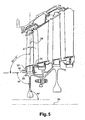
- the rotor 10 comprises turbine discs 11 connected to each other, blades 12 attached to these discs and systems 13 for axially locking the blades on the discs, consisting of rods and flanges arranged between the blades and fixed on the discs, more visible way in figure 2 .
- the rotor 10 is connected to the turbine shaft 14 via a drive cone 15.
- FIG 2 it can be seen that two consecutive turbine discs 20 and 21 are interconnected by a flange 22 which extends perpendicularly between the discs 20 and 21 and along the axis of rotation.
- a snap ring 23 is disposed between a first rotor disc 20 and the flange 22 and another snap ring 25 is disposed between the flange 22 and the other rotor disc 21.
- the axis 24 of the vane blade 12 is perpendicular to the axis of rotation of the rotor, at rest and at normal temperature.
- the figure 3 represents known means of radial retention of a blade 12 on a rotor disk 11, which are of the dovetail type and which comprise a male part 30 formed at one end of the blade 12 attached to the corresponding disk 11 of the rotor, this part being said foot 30 of blade or bulb, and secondly a female portion 31 formed at the periphery of the disc 11 of the rotor by a cavity called cell.
- the blade root 30 has a flat surface 34 parallel to the axis of rotation 10 and facing a substantially flat surface 35 forming the bottom of the cell 31.
- the structure of the rotor is subjected to axial, radial and tangential forces, as well as thermal gradients leading to deformations generating axial parasitic displacements of the free ends of the blades 12.
- the axis 24 of a blade thus takes an orientation 26 not perpendicular to the axis 10 of rotation of the rotor, the inclinations parasitic axis of the blades being directed downstream or upstream.
- the thermal gradients cause an expansion of the constituent material of the blade 12 and a radial parasitic displacement of said blades 12 relative to the axis 10 of rotation of the rotor.
- the surface 35 of the cavity 31 or cell corresponding to the surface 34 of the root 30 of the blade which is perpendicular to the axis of the blade 24, is inclined upstream at an angle ⁇ with respect to the axis 10 of rotation of the rotor.
- the axis 24 is inclined from the angle ⁇ towards the upstream, as represented in FIG. figure 4 .
- the axial, radial and tangential stresses, as well as the thermal gradients leading to deformations generating axial parasitic displacements of the free ends of the blades 12 have the effect that the axis 24 inclines downstream and returns to a position substantially perpendicular to the axis of rotation of the rotor, the angle ⁇ of inclination at rest being determined to compensate as accurately as possible parasitic deviations of the blades 12.
- the surface 34 of the root 30 of the blade corresponding to the surface 35 of the cavity 31 or cavity which is parallel to the axis of rotation of the rotor, is inclined at rest at an angle ⁇ 'upstream by perpendicular to the axis of dawn 24.
- the parasitic displacements of the blades can be directed downstream or upstream in the different stages.
- the fastening device according to the invention makes it possible to incline the axes of the vanes 24 at an angle ⁇ or ⁇ 'upstream or downstream and independently of one another in the various turbine stages to compensate as much as possible the parasitic inclinations of these axes and bring them back into positions perpendicular to the axis of rotation of the rotor in operation.
- turbomachine may comprise both embodiments of the invention, namely on the one hand a several discs in which the cavity surfaces 31, cooperating with the surfaces 34 of the blade roots 30 which are perpendicular to the axes of the blades 24, are inclined at an angle ⁇ with respect to the axis of rotation of the rotor and on the other hand one or more discs in which the surfaces 34 of the blade roots 30, cooperating with the surfaces 35 of the cavities 31 which are parallel to the axis of rotation of the rotor, are inclined at an angle ⁇ 'with respect to the perpendicular to the blade axes 24.
- the connecting device according to the invention is applicable to blade / rotor disc connections whose cavities or cavities 31 are oriented or not parallel to the axis of rotation of the rotor.
- We have shown in figure 6 the case in which the bottom surface 35 of a cavity or cavity 31 is oriented longitudinally in a direction which makes an angle ⁇ with respect to the axis of rotation of the rotor.
- This orientation is also that of the blade root 30 which is housed in the cavity or cell 31.
- the angle ⁇ is the angle between the longitudinal direction of the cavity 31 and the blade root 30. one hand, and one parallel to the axis of rotation on the other hand, in the plane of the figure 6 which is a plane parallel to the axis of rotation of the rotor.
Landscapes
- Engineering & Computer Science (AREA)
- Mechanical Engineering (AREA)
- General Engineering & Computer Science (AREA)
- Physics & Mathematics (AREA)
- Fluid Mechanics (AREA)
- Turbine Rotor Nozzle Sealing (AREA)
- Supercharger (AREA)
Claims (12)
- Turbinenrotor in einer Turbomaschine bzw. einem Turbotriebwerk, enthaltend zumindest eine Scheibe und Schaufeln mit jeweils einem Schaufelfuß (30), der ein Einsteckteil bildet, das in einen Hohlraum (31) mit einer der Rotorscheibe (11) entsprechenden Form eingreift und darin radial festgehalten wird, sowie Sicherungsmittel zum axialen Sichern des Schaufelfußes (30) in dem Hohlraum (31), dadurch gekennzeichnet, dass in Ruhestellung und bei homogenen Temperaturbedingungen die Achse (24) der Schaufel gegenüber einer Senkrechten zur Drehachse (10) des Rotors in Richtung stromaufwärts oder stromabwärts geneigt verläuft, und zwar in einer Richtung und unter einem Winkel, die dazu bestimmt sind, zumindest teilweise die Verlagerung der Achse (24) der Schaufel zu kompensieren, die durch die mechanischen und thermischen Spannungen verursacht wird, denen der Rotor im Betrieb der Turbomaschine bzw. des Turbotriebwerks ausgesetzt ist, wobei die Achse der Schaufel im Wesentlichen senkrecht zur Drehachse des Rotors im Betrieb verläuft.
- Rotor nach Anspruch 1, dadurch gekennzeichnet, dass eine Fläche (35) des Hohlraums (31), die mit einer Fläche (34) des Schaufelfußes (30) zusammenwirkt, welche senkrecht zur Achse (24) der Schaufel verläuft, unter einem Winkel α gegenüber der Drehachse (10) des Rotors geneigt verläuft.
- Rotor nach Anspruch 1, dadurch gekennzeichnet, dass eine Fläche (34) des Schaufelfußes (30), die mit einer Fläche (35) des Hohlraums (31) zusammenwirkt, welche parallel zur Drehachse (10) des Rotors verläuft, unter einem Winkel α' gegenüber der Senkrechten zur Achse (24) der Schaufel geneigt verläuft.
- Rotor nach Anspruch 2 oder 3, dadurch gekennzeichnet, dass der Winkel α oder α' so bestimmt ist, dass die Achsen (24) der Schaufeln im Wesentlichen senkrecht zur Drehachse des Rotors (10) im Betrieb verlaufen.
- Rotor nach einem der Ansprüche 2 bis 4, dadurch gekennzeichnet, dass der Winkel α, α' zwischen -1,5° und +1,5° beträgt.
- Rotor nach einem der Ansprüche 1 bis 5, dadurch gekennzeichnet, dass in Ruhestellung die Achsen (24) der Schaufeln zumindest einer Turbinenstufe in Richtung stromaufwärts gerichtet sind.
- Rotor nach einem der Ansprüche 1 bis 6, dadurch gekennzeichnet, dass in Ruhestellung die Achsen (24) der Schaufeln zumindest einer Turbinenstufe in Richtung stromabwärts gerichtet sind.
- Rotor nach einem der Ansprüche 1 bis 7, dadurch gekennzeichnet, dass die Sicherungsmittel zum axialen Sichern des Schaufelfußes (30) in dem Hohlraum (31) ein Ringrohr (23) aufweisen, das über einen Flansch (22) angedrückt wird, der von der Rotorscheibe (11) getragen wird.
- Rotor nach einem der Ansprüche 1 bis 8, dadurch gekennzeichnet, dass der Hohlraum (31) und der Schaufelfuß (30) eine Längsausrichtung haben, die parallel zur Drehachse (10) des Rotors verläuft oder einen Winkel β mit dieser Achse in einer Ebene parallel zur Drehachse (10) einschließt.
- Rotor nach einem der Ansprüche 1 bis 9, dadurch gekennzeichnet, dass der Schaufelfuß (30) und der Hohlraum (31) schwalbenschwanzartig ausgeführt sind.
- Turbine einer Turbomaschine bzw. eines Turbotriebwerks, dadurch gekennzeichnet, dass sie einen Rotor nach einem der Ansprüche 1 bis 10 enthält.
- Turbomaschine bzw. Turbotriebwerk, dadurch gekennzeichnet, dass sie bzw. es einen Rotor nach einem der Ansprüche 1 bis 10 enthält.
Applications Claiming Priority (2)
| Application Number | Priority Date | Filing Date | Title |
|---|---|---|---|
| FR0312064 | 2003-10-16 | ||
| FR0312064A FR2861128B1 (fr) | 2003-10-16 | 2003-10-16 | Dispositif d'attache d'une aube mobile sur un disque de rotor de turbine dans un turbomachine |
Publications (2)
| Publication Number | Publication Date |
|---|---|
| EP1524406A1 EP1524406A1 (de) | 2005-04-20 |
| EP1524406B1 true EP1524406B1 (de) | 2015-08-19 |
Family
ID=34355485
Family Applications (1)
| Application Number | Title | Priority Date | Filing Date |
|---|---|---|---|
| EP04292380.5A Expired - Lifetime EP1524406B1 (de) | 2003-10-16 | 2004-10-06 | Anordnung einer Turbomaschinenenlaufschaufel |
Country Status (9)
| Country | Link |
|---|---|
| US (1) | US7326035B2 (de) |
| EP (1) | EP1524406B1 (de) |
| JP (1) | JP4173476B2 (de) |
| CN (1) | CN100453772C (de) |
| CA (1) | CA2481883C (de) |
| FR (1) | FR2861128B1 (de) |
| IL (1) | IL164498A0 (de) |
| NO (1) | NO338796B1 (de) |
| RU (1) | RU2343291C2 (de) |
Families Citing this family (16)
| Publication number | Priority date | Publication date | Assignee | Title |
|---|---|---|---|---|
| US20080050238A1 (en) * | 2006-08-24 | 2008-02-28 | Pratt & Whitney Canada Corp. | Disc firtree slot with truncation for blade attachment |
| FR2918106B1 (fr) * | 2007-06-27 | 2011-05-06 | Snecma | Dispositif de retenue axiale d'aubes montees sur un disque de rotor de turbomachine. |
| FR2939129B1 (fr) * | 2008-11-28 | 2014-08-22 | Snecma Propulsion Solide | Aube de turbomachine en materiau composite et procede pour sa fabrication. |
| EP2442088B1 (de) * | 2010-10-12 | 2013-08-28 | Siemens Aktiengesellschaft | Klemmvorrichtung für Turbinenschaufel |
| FR2967202B1 (fr) * | 2010-11-10 | 2013-01-11 | Snecma | Procede d'optimisation du profil d'une aube en materiau composite pour roue mobile de turbomachine |
| EP2472063B1 (de) * | 2010-12-30 | 2015-02-11 | Techspace Aero S.A. | Leitschaufel aus Verbundmaterial |
| EP2971736B1 (de) | 2013-03-13 | 2019-07-10 | Rolls-Royce Corporation | Zwischenschaufelmetallplattform für keramikmatrix- verbundturbinenschaufeln |
| WO2014204542A2 (en) * | 2013-04-01 | 2014-12-24 | United Technologies Corporation | Lightweight blade for gas turbine engine |
| FR3006616B1 (fr) * | 2013-06-05 | 2016-03-04 | Snecma | Preforme d'aube de turbomachine |
| FR3064667B1 (fr) * | 2017-03-31 | 2020-05-15 | Safran Aircraft Engines | Dispositif de refroidissement d'un rotor de turbomachine |
| CN107420135B (zh) * | 2017-08-10 | 2023-09-19 | 杭州汽轮动力集团有限公司 | 一种汽轮机叶片t型叶根及其配合的轮缘槽 |
| US10767498B2 (en) | 2018-04-03 | 2020-09-08 | Rolls-Royce High Temperature Composites Inc. | Turbine disk with pinned platforms |
| US10890081B2 (en) | 2018-04-23 | 2021-01-12 | Rolls-Royce Corporation | Turbine disk with platforms coupled to disk |
| US10577961B2 (en) | 2018-04-23 | 2020-03-03 | Rolls-Royce High Temperature Composites Inc. | Turbine disk with blade supported platforms |
| CN109600003B (zh) * | 2018-12-18 | 2020-11-06 | 中国航发沈阳发动机研究所 | 发动机转子叶片拆装设备 |
| CN114762968B (zh) * | 2021-01-14 | 2024-07-16 | 中国航发商用航空发动机有限责任公司 | 叶片挡环安装工具和叶片挡环安装方法 |
Family Cites Families (17)
| Publication number | Priority date | Publication date | Assignee | Title |
|---|---|---|---|---|
| US1027201A (en) * | 1911-07-08 | 1912-05-21 | Willibald Grun | Turbine-blade. |
| FR480958A (fr) * | 1915-03-01 | 1916-10-19 | Societe Aktiengesellschaft Brown Boveri Et Cie | Aube, pour turbines axiales à vapeur ou à gaz, avec aretes d'entrée et de sortie non parallèles |
| GB260411A (en) * | 1925-10-13 | 1926-11-04 | Gerald Whitehouse Higgs Walker | Improvements relating to turbines |
| US2295012A (en) * | 1941-03-08 | 1942-09-08 | Westinghouse Electric & Mfg Co | Turbine blading |
| DE898150C (de) * | 1943-01-08 | 1953-11-26 | Daimler Benz Ag | Laufrad fuer Turbomaschinen |
| US2669383A (en) * | 1951-02-06 | 1954-02-16 | A V Roe Canada Ltd | Rotor blade |
| DE2217079A1 (de) * | 1972-04-08 | 1973-10-18 | Maschf Augsburg Nuernberg Ag | Laufschaufel fuer axiale turbomaschinen mit daempfungsdraht |
| US3957229A (en) * | 1973-08-09 | 1976-05-18 | Davis Harry C | Convertible auxiliary turbine for aircraft |
| DE2917346C2 (de) * | 1979-04-28 | 1984-11-22 | Dornier Gmbh, 7990 Friedrichshafen | Klappbare Blätter bzw. Schaufeln wahlweise stillsetzbarer Bläser, Turbinen bzw. Propeller |
| US4433955A (en) * | 1981-03-26 | 1984-02-28 | General Electric Company | Turbine arrangement |
| US4460315A (en) * | 1981-06-29 | 1984-07-17 | General Electric Company | Turbomachine rotor assembly |
| CA1206900A (en) * | 1981-12-21 | 1986-07-02 | Raymond L. Downs | Hollow glass shell microcarrier for growth of cell cultures, and method of shell manufacture |
| FR2556409B1 (fr) * | 1983-12-12 | 1991-07-12 | Gen Electric | Aube perfectionnee pour moteur a turbine a gaz et procede de fabrication |
| JPH0571305A (ja) * | 1991-03-04 | 1993-03-23 | General Electric Co <Ge> | ロータブレードをロータデイスクに取付けるプラツトホームアセンブリ |
| FR2723397B1 (fr) * | 1994-08-03 | 1996-09-13 | Snecma | Disque de compresseur de turbomachine muni d'une gorge circulaire asymetrique |
| US6764282B2 (en) * | 2001-11-14 | 2004-07-20 | United Technologies Corporation | Blade for turbine engine |
| FR2857405B1 (fr) * | 2003-07-07 | 2005-09-30 | Snecma Moteurs | Amelioration de la capacite de retention d'une aube a attache marteau dissymetrique |
-
2003
- 2003-10-16 FR FR0312064A patent/FR2861128B1/fr not_active Expired - Lifetime
-
2004
- 2004-10-06 EP EP04292380.5A patent/EP1524406B1/de not_active Expired - Lifetime
- 2004-10-11 IL IL16449804A patent/IL164498A0/xx unknown
- 2004-10-12 US US10/961,064 patent/US7326035B2/en active Active
- 2004-10-13 CA CA2481883A patent/CA2481883C/fr not_active Expired - Lifetime
- 2004-10-14 JP JP2004299644A patent/JP4173476B2/ja not_active Expired - Lifetime
- 2004-10-14 CN CNB2004100881301A patent/CN100453772C/zh not_active Expired - Lifetime
- 2004-10-15 RU RU2004130364/06A patent/RU2343291C2/ru active
- 2004-10-15 NO NO20044403A patent/NO338796B1/no unknown
Also Published As
| Publication number | Publication date |
|---|---|
| NO338796B1 (no) | 2016-10-17 |
| FR2861128A1 (fr) | 2005-04-22 |
| US20050084375A1 (en) | 2005-04-21 |
| IL164498A0 (en) | 2005-12-18 |
| NO20044403L (no) | 2005-04-18 |
| JP4173476B2 (ja) | 2008-10-29 |
| CA2481883A1 (fr) | 2005-04-16 |
| FR2861128B1 (fr) | 2007-06-08 |
| RU2343291C2 (ru) | 2009-01-10 |
| CN1607319A (zh) | 2005-04-20 |
| CA2481883C (fr) | 2011-08-02 |
| EP1524406A1 (de) | 2005-04-20 |
| RU2004130364A (ru) | 2006-04-10 |
| CN100453772C (zh) | 2009-01-21 |
| JP2005121021A (ja) | 2005-05-12 |
| US7326035B2 (en) | 2008-02-05 |
Similar Documents
| Publication | Publication Date | Title |
|---|---|---|
| EP1524406B1 (de) | Anordnung einer Turbomaschinenenlaufschaufel | |
| EP0463955B1 (de) | Befestigung eines Kranzes an einem Turbinenlaufrad | |
| EP1840339B1 (de) | Vorrichtung zur Befestigung von Ringsektoren um ein Turbinenlaufrad einer Strömungsmaschine | |
| EP1873401B1 (de) | Strömungsmaschinenrotor und Strömungsmaschine | |
| CA2518355C (fr) | Retenue des clavettes de centrage des anneaux sous aubes de stator a calage variable d'un moteur a turbine a gaz | |
| EP2060750B1 (de) | Turbinen- oder Kompressorstufe, insbesondere eines Turbotriebwerks | |
| EP1308630B1 (de) | Statorsektor für einen Verdichter eines Turbotriebwerks | |
| EP2366061B1 (de) | Turbinenrad mit einem axialrückhaltesystem für schaufeln | |
| EP2678531B1 (de) | Fanrotor und zugehöriges Turbostrahltriebwerk | |
| CA2647057C (fr) | Distributeur sectorise pour une turbomachine | |
| EP2053203A1 (de) | Verbesserung eines Stellrings für die Anstellung von Leitradschaufeln eines Turbotriebwerks | |
| WO2016092172A1 (fr) | Anneau de commande d'un étage d'aubes à calage variable pour une turbomachine | |
| FR2920469A1 (fr) | Aube a calage variable de turbomachine | |
| FR2974863A1 (fr) | Disque de soufflante de turbomachine | |
| FR2922588A1 (fr) | Disque ou tambour de rotor d'une turbomachine | |
| EP3433469B1 (de) | Plattform, fananordnung und fan | |
| FR3070183B1 (fr) | Turbine pour turbomachine | |
| WO2019224464A1 (fr) | Disque ameliore de soufflante de turbomachine | |
| WO2018002480A1 (fr) | Ensemble de fixation d'un distributeur a un element de structure d'une turbomachine | |
| WO2014037653A1 (fr) | Rotor de soufflante, en particulier pour une turbomachine | |
| FR3073907A1 (fr) | Organe de retention pour plateforme de turbomachine | |
| FR3147836A1 (fr) | Secteur aubage pour roue mobile d’un module de turbomachine d’aeronef, comprenant un dispositif d’amortissement dynamique ameliore | |
| FR3126447A1 (fr) | Roue mobile de turbomachine comprenant une pièce de butée axiale pour amortisseur | |
| FR3102796A1 (fr) | Plateformes inter-aubes | |
| FR3094400A1 (fr) | Rotor de soufflante pour turbomachine |
Legal Events
| Date | Code | Title | Description |
|---|---|---|---|
| PUAI | Public reference made under article 153(3) epc to a published international application that has entered the european phase |
Free format text: ORIGINAL CODE: 0009012 |
|
| AK | Designated contracting states |
Kind code of ref document: A1 Designated state(s): AT BE BG CH CY CZ DE DK EE ES FI FR GB GR HU IE IT LI LU MC NL PL PT RO SE SI SK TR |
|
| AX | Request for extension of the european patent |
Extension state: AL HR LT LV MK |
|
| RAP1 | Party data changed (applicant data changed or rights of an application transferred) |
Owner name: SNECMA |
|
| 17P | Request for examination filed |
Effective date: 20051005 |
|
| AKX | Designation fees paid |
Designated state(s): DE FR GB SE |
|
| GRAP | Despatch of communication of intention to grant a patent |
Free format text: ORIGINAL CODE: EPIDOSNIGR1 |
|
| INTG | Intention to grant announced |
Effective date: 20150304 |
|
| GRAS | Grant fee paid |
Free format text: ORIGINAL CODE: EPIDOSNIGR3 |
|
| GRAA | (expected) grant |
Free format text: ORIGINAL CODE: 0009210 |
|
| AK | Designated contracting states |
Kind code of ref document: B1 Designated state(s): DE FR GB SE |
|
| REG | Reference to a national code |
Ref country code: GB Ref legal event code: FG4D Free format text: NOT ENGLISH |
|
| REG | Reference to a national code |
Ref country code: DE Ref legal event code: R096 Ref document number: 602004047702 Country of ref document: DE |
|
| REG | Reference to a national code |
Ref country code: FR Ref legal event code: PLFP Year of fee payment: 12 |
|
| REG | Reference to a national code |
Ref country code: SE Ref legal event code: TRGR |
|
| REG | Reference to a national code |
Ref country code: DE Ref legal event code: R097 Ref document number: 602004047702 Country of ref document: DE |
|
| PLBE | No opposition filed within time limit |
Free format text: ORIGINAL CODE: 0009261 |
|
| STAA | Information on the status of an ep patent application or granted ep patent |
Free format text: STATUS: NO OPPOSITION FILED WITHIN TIME LIMIT |
|
| 26N | No opposition filed |
Effective date: 20160520 |
|
| REG | Reference to a national code |
Ref country code: FR Ref legal event code: PLFP Year of fee payment: 13 |
|
| REG | Reference to a national code |
Ref country code: FR Ref legal event code: PLFP Year of fee payment: 14 |
|
| REG | Reference to a national code |
Ref country code: FR Ref legal event code: CD Owner name: SAFRAN AIRCRAFT ENGINES, FR Effective date: 20170719 |
|
| REG | Reference to a national code |
Ref country code: FR Ref legal event code: PLFP Year of fee payment: 15 |
|
| PGFP | Annual fee paid to national office [announced via postgrant information from national office to epo] |
Ref country code: GB Payment date: 20230920 Year of fee payment: 20 |
|
| PGFP | Annual fee paid to national office [announced via postgrant information from national office to epo] |
Ref country code: SE Payment date: 20230922 Year of fee payment: 20 Ref country code: FR Payment date: 20230920 Year of fee payment: 20 |
|
| PGFP | Annual fee paid to national office [announced via postgrant information from national office to epo] |
Ref country code: DE Payment date: 20230920 Year of fee payment: 20 |
|
| REG | Reference to a national code |
Ref country code: DE Ref legal event code: R071 Ref document number: 602004047702 Country of ref document: DE |
|
| REG | Reference to a national code |
Ref country code: GB Ref legal event code: PE20 Expiry date: 20241005 |
|
| REG | Reference to a national code |
Ref country code: SE Ref legal event code: EUG |
|
| PG25 | Lapsed in a contracting state [announced via postgrant information from national office to epo] |
Ref country code: GB Free format text: LAPSE BECAUSE OF EXPIRATION OF PROTECTION Effective date: 20241005 |
|
| PG25 | Lapsed in a contracting state [announced via postgrant information from national office to epo] |
Ref country code: GB Free format text: LAPSE BECAUSE OF EXPIRATION OF PROTECTION Effective date: 20241005 |