EP1495773A2 - Centrifugal fluid pump apparatus - Google Patents
Centrifugal fluid pump apparatus Download PDFInfo
- Publication number
- EP1495773A2 EP1495773A2 EP04015954A EP04015954A EP1495773A2 EP 1495773 A2 EP1495773 A2 EP 1495773A2 EP 04015954 A EP04015954 A EP 04015954A EP 04015954 A EP04015954 A EP 04015954A EP 1495773 A2 EP1495773 A2 EP 1495773A2
- Authority
- EP
- European Patent Office
- Prior art keywords
- impeller
- electromagnet
- function
- rotor
- current
- Prior art date
- Legal status (The legal status is an assumption and is not a legal conclusion. Google has not performed a legal analysis and makes no representation as to the accuracy of the status listed.)
- Granted
Links
- 239000012530 fluid Substances 0.000 title claims abstract description 58
- 238000012544 monitoring process Methods 0.000 claims abstract description 59
- 238000001514 detection method Methods 0.000 claims abstract description 50
- 230000008878 coupling Effects 0.000 claims abstract description 28
- 238000010168 coupling process Methods 0.000 claims abstract description 28
- 238000005859 coupling reaction Methods 0.000 claims abstract description 28
- 238000005339 levitation Methods 0.000 claims abstract description 27
- 230000007246 mechanism Effects 0.000 claims abstract description 19
- 239000008280 blood Substances 0.000 claims description 36
- 210000004369 blood Anatomy 0.000 claims description 36
- 239000000696 magnetic material Substances 0.000 claims description 19
- 230000007257 malfunction Effects 0.000 description 4
- 238000010276 construction Methods 0.000 description 3
- 230000000694 effects Effects 0.000 description 3
- 230000004907 flux Effects 0.000 description 2
- 239000007788 liquid Substances 0.000 description 2
- 241000894006 Bacteria Species 0.000 description 1
- 208000007536 Thrombosis Diseases 0.000 description 1
- 230000002159 abnormal effect Effects 0.000 description 1
- 230000009471 action Effects 0.000 description 1
- 238000013459 approach Methods 0.000 description 1
- 230000017531 blood circulation Effects 0.000 description 1
- 238000004891 communication Methods 0.000 description 1
- 238000010586 diagram Methods 0.000 description 1
- 230000005484 gravity Effects 0.000 description 1
- 230000009545 invasion Effects 0.000 description 1
- 210000004072 lung Anatomy 0.000 description 1
- 238000003754 machining Methods 0.000 description 1
- 238000000034 method Methods 0.000 description 1
- 238000012986 modification Methods 0.000 description 1
- 230000004048 modification Effects 0.000 description 1
- 230000005405 multipole Effects 0.000 description 1
- 230000008569 process Effects 0.000 description 1
- 238000005086 pumping Methods 0.000 description 1
- 238000011084 recovery Methods 0.000 description 1
- 229910001220 stainless steel Inorganic materials 0.000 description 1
- 239000010935 stainless steel Substances 0.000 description 1
- 230000001960 triggered effect Effects 0.000 description 1
Images


Classifications
-
- F—MECHANICAL ENGINEERING; LIGHTING; HEATING; WEAPONS; BLASTING
- F16—ENGINEERING ELEMENTS AND UNITS; GENERAL MEASURES FOR PRODUCING AND MAINTAINING EFFECTIVE FUNCTIONING OF MACHINES OR INSTALLATIONS; THERMAL INSULATION IN GENERAL
- F16C—SHAFTS; FLEXIBLE SHAFTS; ELEMENTS OR CRANKSHAFT MECHANISMS; ROTARY BODIES OTHER THAN GEARING ELEMENTS; BEARINGS
- F16C32/00—Bearings not otherwise provided for
- F16C32/04—Bearings not otherwise provided for using magnetic or electric supporting means
- F16C32/0406—Magnetic bearings
- F16C32/044—Active magnetic bearings
- F16C32/0442—Active magnetic bearings with devices affected by abnormal, undesired or non-standard conditions such as shock-load, power outage, start-up or touchdown
-
- A—HUMAN NECESSITIES
- A61—MEDICAL OR VETERINARY SCIENCE; HYGIENE
- A61M—DEVICES FOR INTRODUCING MEDIA INTO, OR ONTO, THE BODY; DEVICES FOR TRANSDUCING BODY MEDIA OR FOR TAKING MEDIA FROM THE BODY; DEVICES FOR PRODUCING OR ENDING SLEEP OR STUPOR
- A61M60/00—Blood pumps; Devices for mechanical circulatory actuation; Balloon pumps for circulatory assistance
- A61M60/10—Location thereof with respect to the patient's body
- A61M60/104—Extracorporeal pumps, i.e. the blood being pumped outside the patient's body
- A61M60/109—Extracorporeal pumps, i.e. the blood being pumped outside the patient's body incorporated within extracorporeal blood circuits or systems
-
- A—HUMAN NECESSITIES
- A61—MEDICAL OR VETERINARY SCIENCE; HYGIENE
- A61M—DEVICES FOR INTRODUCING MEDIA INTO, OR ONTO, THE BODY; DEVICES FOR TRANSDUCING BODY MEDIA OR FOR TAKING MEDIA FROM THE BODY; DEVICES FOR PRODUCING OR ENDING SLEEP OR STUPOR
- A61M60/00—Blood pumps; Devices for mechanical circulatory actuation; Balloon pumps for circulatory assistance
- A61M60/20—Type thereof
- A61M60/205—Non-positive displacement blood pumps
- A61M60/216—Non-positive displacement blood pumps including a rotating member acting on the blood, e.g. impeller
- A61M60/226—Non-positive displacement blood pumps including a rotating member acting on the blood, e.g. impeller the blood flow through the rotating member having mainly radial components
- A61M60/232—Centrifugal pumps
-
- A—HUMAN NECESSITIES
- A61—MEDICAL OR VETERINARY SCIENCE; HYGIENE
- A61M—DEVICES FOR INTRODUCING MEDIA INTO, OR ONTO, THE BODY; DEVICES FOR TRANSDUCING BODY MEDIA OR FOR TAKING MEDIA FROM THE BODY; DEVICES FOR PRODUCING OR ENDING SLEEP OR STUPOR
- A61M60/00—Blood pumps; Devices for mechanical circulatory actuation; Balloon pumps for circulatory assistance
- A61M60/40—Details relating to driving
- A61M60/403—Details relating to driving for non-positive displacement blood pumps
- A61M60/419—Details relating to driving for non-positive displacement blood pumps the force acting on the blood contacting member being permanent magnetic, e.g. from a rotating magnetic coupling between driving and driven magnets
-
- A—HUMAN NECESSITIES
- A61—MEDICAL OR VETERINARY SCIENCE; HYGIENE
- A61M—DEVICES FOR INTRODUCING MEDIA INTO, OR ONTO, THE BODY; DEVICES FOR TRANSDUCING BODY MEDIA OR FOR TAKING MEDIA FROM THE BODY; DEVICES FOR PRODUCING OR ENDING SLEEP OR STUPOR
- A61M60/00—Blood pumps; Devices for mechanical circulatory actuation; Balloon pumps for circulatory assistance
- A61M60/50—Details relating to control
- A61M60/508—Electronic control means, e.g. for feedback regulation
- A61M60/538—Regulation using real-time blood pump operational parameter data, e.g. motor current
-
- A—HUMAN NECESSITIES
- A61—MEDICAL OR VETERINARY SCIENCE; HYGIENE
- A61M—DEVICES FOR INTRODUCING MEDIA INTO, OR ONTO, THE BODY; DEVICES FOR TRANSDUCING BODY MEDIA OR FOR TAKING MEDIA FROM THE BODY; DEVICES FOR PRODUCING OR ENDING SLEEP OR STUPOR
- A61M60/00—Blood pumps; Devices for mechanical circulatory actuation; Balloon pumps for circulatory assistance
- A61M60/80—Constructional details other than related to driving
- A61M60/802—Constructional details other than related to driving of non-positive displacement blood pumps
- A61M60/81—Pump housings
- A61M60/816—Sensors arranged on or in the housing, e.g. ultrasound flow sensors
-
- A—HUMAN NECESSITIES
- A61—MEDICAL OR VETERINARY SCIENCE; HYGIENE
- A61M—DEVICES FOR INTRODUCING MEDIA INTO, OR ONTO, THE BODY; DEVICES FOR TRANSDUCING BODY MEDIA OR FOR TAKING MEDIA FROM THE BODY; DEVICES FOR PRODUCING OR ENDING SLEEP OR STUPOR
- A61M60/00—Blood pumps; Devices for mechanical circulatory actuation; Balloon pumps for circulatory assistance
- A61M60/80—Constructional details other than related to driving
- A61M60/802—Constructional details other than related to driving of non-positive displacement blood pumps
- A61M60/818—Bearings
- A61M60/82—Magnetic bearings
- A61M60/822—Magnetic bearings specially adapted for being actively controlled
-
- A—HUMAN NECESSITIES
- A61—MEDICAL OR VETERINARY SCIENCE; HYGIENE
- A61M—DEVICES FOR INTRODUCING MEDIA INTO, OR ONTO, THE BODY; DEVICES FOR TRANSDUCING BODY MEDIA OR FOR TAKING MEDIA FROM THE BODY; DEVICES FOR PRODUCING OR ENDING SLEEP OR STUPOR
- A61M60/00—Blood pumps; Devices for mechanical circulatory actuation; Balloon pumps for circulatory assistance
- A61M60/80—Constructional details other than related to driving
- A61M60/802—Constructional details other than related to driving of non-positive displacement blood pumps
- A61M60/818—Bearings
- A61M60/824—Hydrodynamic or fluid film bearings
-
- F—MECHANICAL ENGINEERING; LIGHTING; HEATING; WEAPONS; BLASTING
- F04—POSITIVE - DISPLACEMENT MACHINES FOR LIQUIDS; PUMPS FOR LIQUIDS OR ELASTIC FLUIDS
- F04D—NON-POSITIVE-DISPLACEMENT PUMPS
- F04D15/00—Control, e.g. regulation, of pumps, pumping installations or systems
- F04D15/0066—Control, e.g. regulation, of pumps, pumping installations or systems by changing the speed, e.g. of the driving engine
-
- F—MECHANICAL ENGINEERING; LIGHTING; HEATING; WEAPONS; BLASTING
- F04—POSITIVE - DISPLACEMENT MACHINES FOR LIQUIDS; PUMPS FOR LIQUIDS OR ELASTIC FLUIDS
- F04D—NON-POSITIVE-DISPLACEMENT PUMPS
- F04D15/00—Control, e.g. regulation, of pumps, pumping installations or systems
- F04D15/0077—Safety measures
-
- F—MECHANICAL ENGINEERING; LIGHTING; HEATING; WEAPONS; BLASTING
- F04—POSITIVE - DISPLACEMENT MACHINES FOR LIQUIDS; PUMPS FOR LIQUIDS OR ELASTIC FLUIDS
- F04D—NON-POSITIVE-DISPLACEMENT PUMPS
- F04D29/00—Details, component parts, or accessories
- F04D29/04—Shafts or bearings, or assemblies thereof
- F04D29/046—Bearings
- F04D29/047—Bearings hydrostatic; hydrodynamic
-
- F—MECHANICAL ENGINEERING; LIGHTING; HEATING; WEAPONS; BLASTING
- F04—POSITIVE - DISPLACEMENT MACHINES FOR LIQUIDS; PUMPS FOR LIQUIDS OR ELASTIC FLUIDS
- F04D—NON-POSITIVE-DISPLACEMENT PUMPS
- F04D29/00—Details, component parts, or accessories
- F04D29/04—Shafts or bearings, or assemblies thereof
- F04D29/046—Bearings
- F04D29/048—Bearings magnetic; electromagnetic
-
- F—MECHANICAL ENGINEERING; LIGHTING; HEATING; WEAPONS; BLASTING
- F05—INDEXING SCHEMES RELATING TO ENGINES OR PUMPS IN VARIOUS SUBCLASSES OF CLASSES F01-F04
- F05B—INDEXING SCHEME RELATING TO WIND, SPRING, WEIGHT, INERTIA OR LIKE MOTORS, TO MACHINES OR ENGINES FOR LIQUIDS COVERED BY SUBCLASSES F03B, F03D AND F03G
- F05B2240/00—Components
- F05B2240/50—Bearings
- F05B2240/51—Bearings magnetic
-
- F—MECHANICAL ENGINEERING; LIGHTING; HEATING; WEAPONS; BLASTING
- F05—INDEXING SCHEMES RELATING TO ENGINES OR PUMPS IN VARIOUS SUBCLASSES OF CLASSES F01-F04
- F05B—INDEXING SCHEME RELATING TO WIND, SPRING, WEIGHT, INERTIA OR LIKE MOTORS, TO MACHINES OR ENGINES FOR LIQUIDS COVERED BY SUBCLASSES F03B, F03D AND F03G
- F05B2240/00—Components
- F05B2240/50—Bearings
- F05B2240/53—Hydrodynamic or hydrostatic bearings
-
- F—MECHANICAL ENGINEERING; LIGHTING; HEATING; WEAPONS; BLASTING
- F16—ENGINEERING ELEMENTS AND UNITS; GENERAL MEASURES FOR PRODUCING AND MAINTAINING EFFECTIVE FUNCTIONING OF MACHINES OR INSTALLATIONS; THERMAL INSULATION IN GENERAL
- F16C—SHAFTS; FLEXIBLE SHAFTS; ELEMENTS OR CRANKSHAFT MECHANISMS; ROTARY BODIES OTHER THAN GEARING ELEMENTS; BEARINGS
- F16C2360/00—Engines or pumps
- F16C2360/44—Centrifugal pumps
Definitions
- the present invention relates to a centrifugal fluid pump apparatus, and in particular to a centrifugal fluid pump for pumping a medical fluid, such as blood.
- centrifugal blood pumps are increasingly used in artificial heart/lung units for extracorporeal blood circulation.
- Centrifugal pumps of the magnetic coupling type wherein a driving torque from an external motor is transmitted to an impeller through magnetic coupling are commonly used because the physical communication between the blood chamber of the pump and the exterior can be completely excluded and invasion of bacteria is prevented.
- the centrifugal blood pump includes a housing having a blood inlet port and a blood outlet port and an impeller rotatably accommodated in the housing to feed blood by a centrifugal force generated during its rotation.
- the impeller having a permanent magnet disposed therein, is rotated by a rotor having magnets for attracting the magnet of the impeller thereto and by a rotational torque generation mechanism having a motor for rotating the rotor.
- the impeller rotates without contacting the housing, with the impeller being attracted to the side opposite to the rotor-disposed side by a magnetic force. This state is termed a magnetic levitation state.
- the centrifugal pump of a magnetic levitation type has three sensors for detecting the position of the impeller and three impeller attraction electromagnets.
- the position of the impeller is controlled by controlling electric current to be applied to the electromagnets, based on information of the impeller provided by the sensors for detecting the position of the impeller.
- the centrifugal fluid pump apparatus comprises a pump body in which an impeller rotates without contacting a housing; and a control mechanism for said pump body, said pump body including: said housing having a blood inlet port and a blood outlet port; a centrifugal pump section including an impeller having a first magnetic material and a second magnetic material and rotating in said housing to feed a fluid by a centrifugal force generated during its rotation; an impeller rotational torque generation section including a rotor having a magnet for attracting said first magnetic material of said impeller and a motor for rotating said rotor; an impeller position control section having an electromagnet for attracting said second magnetic material of said impeller; a position sensor for detecting a position of said impeller; and hydrodynamic bearing means provided on an inner surface of said housing at a side of said rotor or on a surface of said impeller at a side of said rotor, said control mechanism comprising: a position sensor output monitoring function or an electromagnet current monitoring function; a motor current monitoring function;
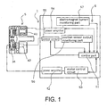
- Centrifugal fluid pump apparatus 1 includes a pump body 5 in which an impeller 21 rotates without contacting a housing 20; and a control mechanism 6 for the body 5.
- the pump body 5 includes the housing 20 having a blood inlet port 22 and a blood outlet port 23; a centrifugal fluid pump section 2 including an impeller 21 having a first magnetic material 25 and a second magnetic material 28 disposed therein and rotating in the housing 20 to feed a fluid by a centrifugal force generated during its rotation; an impeller rotational torque generation section 3 including a rotor 31 having a magnet 33 for attracting thereto the first magnetic material 25 of the impeller 21 and a motor 34 for rotating the rotor 31; an impeller position control section 4 having an electromagnet 41 (electromagnet for attracting the second magnetic material 28 of the impeller 21 thereto) for attracting the impeller 21 thereto, a position sensor 42 (position sensor for detecting the position of the second magnetic material 28 of the impeller 21) for detecting the position of the impeller 21, and a groove 38 for hydrodynamic bearing provided on an inner surface of the housing 20 at the side of the rotor 31 or a surface of the impeller
- the control mechanism 6 has a position sensor output monitoring part (position sensor output monitoring function) 56, a motor current monitoring function or an electromagnet current monitoring function 57, and a failure detection function.
- the failure detection function for determining a failure of the sensor 42 by using said position sensor output monitoring function or a failure of the electromagnet 41 by using said electromagnet current monitoring function.
- control mechanism 6 has the position sensor output monitoring function 56, the electromagnet current monitoring function 57, the motor current monitoring function, and the failure detection function of determining whether the sensor has a failure by using the position sensor output monitoring function 56 and whether the electromagnet has a failure by using the electromagnet current monitoring function 57.
- the centrifugal fluid pump apparatus 1 has an emergency impeller rotation function that operates when the failure detection function has detected that the sensor or the electromagnet has a failure to rotate the impeller 21 by utilizing the groove 38 for hydrodynamic bearing without substantial contact between the impeller 21 and the housing 20.
- the emergency impeller rotation function includes a rotation termination function of terminating current to the motor and the electromagnet 41 when the failure detection function detects a failure to thereby terminate rotation of the rotor 31 and the impeller 21; impeller magnetic counterforce application function to apply a current to the electromagnet 41 sufficient to overcome the magnetic attraction force of the rotor 31 to the impeller 21 caused by the permanent magnet 33; a hydrodynamic levitation control detection function detecting that a hydraulic bearing coupling between the impeller and the rotor has been made and that there is rotation of the impeller, i.e., there is a magnetic rotational coupling achieved under hydraulic bearing conditions, by using a motor current monitored by the motor current monitoring function; a motor speed control function for increasing the motor speed and hence the impeller rotation speed up to a predetermined value (for example, gradually, namely, successively or stepwise) after the hydrodynamic levitation control detection function detects that the hydraulic bearing coupling between the impeller and the rotor has been made; and impeller magnetic counterforce termination function to terminate current to
- the centrifugal fluid pump apparatus 1 of the present invention has the function of shifting from the non-contact (magnetic) rotational coupling of the impeller by means of the magnetic bearing to the non-contact (magnetic) rotational coupling of the impeller by means of the hydrodynamic bearing, i.e., the groove, that generates a pressure.
- the body 5 has the housing 20 having the blood inlet port 22 and the blood outlet port 23, the centrifugal fluid pump section 2 having the impeller 21 rotating inside the housing 20 to feed blood by a centrifugal force generated during its rotation, the impeller rotational torque generation section (non-contact type magnetic bearing constructing section) 3 for the impeller 21, and the impeller position control section (contact type magnetic bearing constructing section) 4 for the impeller 21.
- the impeller 21 rotates without contacting the inner surface of the housing 20, with the impeller 21 held at a predetermined position inside the housing 20 by the operation of the non-contact type magnetic bearing constructing section 3 and that of the contact type magnetic bearing constructing section 4.
- the housing 20 has the blood inlet port 22 and the blood outlet port 23 and is formed of a non-magnetic material.
- the housing 20 accommodates a blood chamber 24 communicating with the blood inlet and outlet ports 22 and 23.
- the housing 20 also accommodates the impeller 21 therein.
- the blood inlet port 22 projects substantially vertically from the vicinity of the center of the upper surface of the housing 20.
- the blood outlet port 23 projects tangentially from a side surface of the approximately cylindrical housing 20.
- the disc-shaped impeller 21 having a through-hole in the center thereof is accommodated inside the blood chamber 24 formed inside the housing 20.
- Fig. 5 the disc-shaped impeller 21 having a through-hole in the center thereof is accommodated inside the blood chamber 24 formed inside the housing 20.
- a preferred embodiment of the impeller 21 includes an annular plate-shaped member (lower shroud) 27 forming the lower surface thereof, an annular plate-shaped member (upper shroud) 28 forming the upper surface thereof and opening at the center thereof, and a plurality of (for example, seven) vanes 18 formed between the lower shroud 27 and the upper shroud 28.
- a plurality of (for example, seven) blood passages 26 partitioned from one another by the adjacent vanes 18 is formed between the lower shroud 27 and the upper shroud 28. As shown in Fig.
- each of the blood passages 26 communicates with the center opening of the impeller 21 and extends from the center opening of the impeller 21 to its periphery, with each of the blood passages 26 becoming gradually larger in the width thereof.
- the vanes 18 are formed between the adjacent blood passages 26.
- the vanes 18 and blood passages 26 are spaced at equiangular intervals and in substantially the same shape.
- a plurality (for example, 24) of the first magnetic materials 25 are embedded in the impeller 21.
- the first magnetic materials 25 are embedded in the lower shroud 27.
- the embedded first magnetic materials 25 are provided so that the impeller 21 is attracted toward the side opposite to the side where the blood inlet port 22 (in other words, a side of the rotor 31) is disposed by a permanent magnet 33 provided in the rotor 31 of the rotational torque generation section 3 to be described later and that the rotational torque is transmitted from the rotational torque generation section 3 to the impeller 21.
- each of the first magnetic materials 25 is circular in a horizontal cross section.
- a ring-shaped magnet having multi-poles for example, 24 poles.
- a plurality of small magnets may be arranged in the shape of a ring in such a way that positive and negative poles alternate with each other.
- the impeller 21 further includes the second magnetic member 28 which itself constitutes the upper shroud or which is provided inside the upper shroud.
- the entire upper shroud is constructed of the second magnetic member 28.
- the second magnetic member 28 is provided so that the electromagnet 41 of the impeller position control section 4, to be described later, attracts the impeller 21 magnetically toward the blood inlet port 22.
- the second magnetic member 28 is made of magnetic stainless steel.
- the impeller position control section 4 and the rotational torque generation section 3 constitute a non-contact type magnetic bearing, which magnetically attracts the impeller 21 from opposite directions. Thereby the impeller 21 is held steadily at a proper position not in contact with the inner surface of the housing 20 and rotates inside the housing 20 without contacting its inner surface.
- the rotor 31 accommodated in the housing 20 and a motor 34 for rotating the rotor 31.
- the rotor 31 has a plurality of permanent magnets 33 disposed on a surface thereof at the side of the centrifugal fluid pump section 2.
- the center of the rotor 31 is fixedly secured to the rotational shaft of the motor 34.
- a plurality of the permanent magnets 33 are equiangularly distributed in accordance with the arrangement mode (number and position) of the permanent magnets 25 of the impeller 21.
- the impeller rotation torque generation section 3 is not limited to the illustrated one having the rotor and motor.
- a plurality of stator coils may be used as the impeller rotation torque generation section 3 as long as they can attract the permanent magnets 25 of the impeller 21 thereto and drive the impeller 21 for rotation.
- a plurality of electromagnets 41 included in the impeller position control section 4 are a plurality of electromagnets 41, accommodated in the housing 20, for attracting the second magnetic member 28 of the impeller 21 thereto and a plurality of position sensors 42 for detecting the positions of the second magnetic members 28 of the impeller 21.
- the electromagnets (three) 41 and the position sensors (three) 42 are spaced at equiangular intervals respectively.
- the electromagnets 41 and the sensors 42 are also spaced at equiangular intervals.
- Each of the electromagnets 41 includes a core and a coil. Three electromagnets 41 are arranged in the preferred embodiment, but other quantities, such as, for example, four electromagnets may also be provided.
- Each of the position sensors 42 detects the distance of the gap between the electromagnet 41 and the second magnetic member 28.
- An output of the position sensor 42 indicating the result of the detection is sent to a control part 51 of the control mechanism 6 for controlling electric current to be applied to the coil of the electromagnet (hereinafter referred to as electromagnet current) or a voltage to be applied thereto.
- electromagnet current electric current to be applied to the coil of the electromagnet
- the housing 20 accommodates the impeller 21 and has the groove 38 for hydrodynamic bearing formed on an inner surface 20a of the housing 20 at the rotor-disposed side, the inner surface 20a of which forms the blood chamber 24.
- the magnetic bearing stops in other words, when the operation of the electromagnet stops and magnetic levitation state is lost
- a hydrodynamic levitation effect is generated between the groove 38 for hydrodynamic bearing and the impeller 21, if the rotation of the impeller 21 is maintained at a speed more than a predetermined value, as discussed below, thereby allowing the impeller 21 to rotate without contacting the inner surface of the housing 20.
- the groove 38 for hydrodynamic bearing has a size corresponding to that of the bottom surface of the impeller 21 (the surface of a rotor side).
- the groove 38 for hydrodynamic bearing extends spirally (in other words, curved) outwardly to the vicinity of the outer edge of the inner surface 20a, with one end of the groove 38 for hydrodynamic bearing disposed on the circumference of a circle spaced outward at a short distance from the center of the inner surface 20a of the housing 20 and with the width thereof becoming outwardly gradually larger.
- a plurality of the grooves 38 for hydrodynamic bearing has substantially the same configuration and is spaced at almost equal intervals.
- Each of the grooves 38 for hydrodynamic bearing is concavely formed.
- the depth thereof is in the range of 0.01 mm to 0.2 mm. It is also preferable that the number of the grooves 38 for hydrodynamic bearing is in the range of six to thirty-six. In the preferred embodiment, twelve grooves 38 for hydrodynamic bearing are provided at equiangular intervals around the center of the axis of the impeller 21.
- the groove 38 for hydrodynamic bearing may be disposed on the surface of the impeller 21 at the side of the rotor 31 instead of disposing it on the housing 20. It is preferable that the groove 38 for hydrodynamic bearing disposed on the surface of the impeller 21 at the side of the rotor 31 has the same construction as that of the groove 38 for hydrodynamic bearing disposed on the inner surface of the housing 20.
- the groove 38 for hydrodynamic bearing having the above-described construction is attracted toward the impeller torque generation section 3, when the impeller position control section 4 does not operate. Owing to the hydrodynamic bearing effect generated between the groove 38 for hydrodynamic bearing and the bottom surface of the impeller 21 (or between the groove 38 for hydrodynamic bearing and the inner surface of the housing), the impeller 21 rotates at a position spaced at a short distance from the inner surface of the housing 20 without contacting the inner surface thereof, thus providing a blood passage between the lower surface of the impeller 21 and the inner surface of the housing 20. Thereby it is possible to prevent blood from staying therebetween and thrombus from occurring owing to the stay of the blood therebetween. In addition, the groove 38 for hydrodynamic bearing displays an agitating action between the lower surface of the impeller 21 and the inner surface of the housing 20 in a normal state, thus preventing the blood from partially staying therebetween.
- the control mechanism 6 includes a power amplifier 52 for the magnetic coupling motor 34, a motor control circuit 53, a power amplifier 54 for the electromagnet 41, the electromagnet current monitoring part 57 for monitoring electric current to be applied to the electromagnet 41, a sensor circuit 55 for the sensor 42, the position sensor output monitoring part 56 for monitoring the output of the sensor 42, and the control part 51.
- the control part 51 has the motor current monitoring function.
- control mechanism 6 has both the electromagnet current monitoring part 57 and the position sensor output monitoring part 56. But alternatively, the control mechanism 6 may have the electromagnet current monitoring part 57 or the position sensor output monitoring part 56.
- the centrifugal fluid pump apparatus 1 has an emergency impeller rotation function that operates when the failure detection function detects that the sensor or the electromagnet has a failure and allows the impeller 21 to rotate without contacting the housing 20 by utilizing the groove 38 for hydrodynamic bearing.
- the control part 51 has the failure detection function of determining whether the sensor has a failure by using an output of the electromagnet current monitoring part or an output of the sensor output monitoring part; a rotation termination function of terminating current to the motor and the electromagnet 41 when the failure detection function detects a failure to thereby terminate rotation of the rotor 31 and the impeller 21; impeller magnetic counterforce application function to apply a current to the electromagnet 41 sufficient to overcome the magnetic attraction force of the rotor 31 to the impeller 21 caused by the permanent magnet 33; a hydrodynamic levitation control detection function of detecting rotation of the impeller and the rotor by using a motor current monitored by the motor current monitoring function; a motor speed control function for increasing the motor speed and hence the impeller rotation speed up to a pre
- the control mechanism 6 of the centrifugal pump of the embodiment has the position sensor output monitoring function and the electromagnet current monitoring function.
- the control mechanism 6 detects that an output of the position sensor (plural systems are provided) or electromagnet current (plural systems are provided) deviates from a normal range, which means that control of the magnetic bearing cannot be performed owing to the magnetic levitation failure, the control mechanism 6 shifts the non-contact rotation of the impeller by means of the magnetic bearing to the non-contact rotation thereof by means of the groove 38 for hydrodynamic bearing.
- the output of the sensor deviates from its normal range. For example, if a reluctance sensor has disconnection, the output thereof deviates from its normal range.
- the centrifugal fluid pump apparatus of the embodiment has a sensor circuit having a function of generating a predetermined output value exceeding the normal level when the sensor system has disconnection. More specifically, in the case where the normal range of the output of the sensor circuit is in the range of -1 to +1 [V] as the output of the sensor, the output of the sensor circuit is +2.5 [V] (predetermined value) when the sensor system has disconnection. Therefore the failure detection function is capable of determining easily and securely that the sensor has a failure (disconnection), when an output value of the sensor monitored by the sensor output monitoring function is equal to the predetermined output value at the time when the sensor system has disconnection.
- the centrifugal fluid pump apparatus of the embodiment has a circuit for the electromagnet.
- the electromagnet circuit used in the preferred embodiment is of a type not energized when the electromagnet has disconnection. More specifically, the normal range of electric current to be applied to the electromagnet circuit is in the range of 1 to 2 [A]. When the electromagnet circuit has disconnection, an electric current of 0 [A] is applied thereto. Accordingly, the failure detection function is capable of determining easily and securely that the electromagnet has a failure (disconnection), when the electromagnet current monitoring function monitors that electric current is not applied to the electromagnet circuit.
- the centrifugal fluid pump apparatus of the embodiment has a plurality of electromagnets.
- the electromagnet monitoring function monitors the output of each of the electromagnets. If any one of the electromagnets has a failure, the failure detection function determines that the electromagnet has a failure.
- the centrifugal fluid pump apparatus of the embodiment has a plurality of position sensors.
- the sensor output monitoring function monitors the output of each of the position sensors. If any one of the position sensors, the failure detection function determines that the position sensor has a failure.
- the dynamic pressure bearing constructed of the groove for hydrodynamic levitation control is a system of maintaining the non-contact between the impeller 21 and the housing 20 by virtue of the pressure generated by the groove for hydrodynamic bearing, which thereby establishes a hydraulic bearing coupling.
- the impeller 21 is required to rotate at more than a certain speed.
- the magnetic coupling between the impeller and the rotor should be normal. If a failure has occurred in the control system of the magnetic bearing, the magnetic coupling between the impeller and the rotor becomes abnormal.
- the impeller is capable of accomplishing a stable non-contact rotation by means of the groove for hydrodynamic bearing, when the impeller speed (the rotor speed) is in the range of 1000 to 3000 rpm, preferably about 1200rpm.
- the failure detection function detects a failure
- the current to the motor and to the electromagnet 41 is stopped and one waits for termination of rotation of the impeller. Consequently, the impeller 21 is attracted toward the rotor 31 and approaches the inner surface of the housing 20 due to the unbalanced magnetic attraction force from permanent magnet 33. More specifically, the impeller 21 becomes strongly magnetically attracted to the rotor 31 and encounters strong frictional forces such that it is unable to freely rotate.
- the impeller magnetic counterforce application function applies a current to the electromagnet 41 sufficient to overcome the magnetic attraction force of the rotor 31 to the impeller 21 caused by the permanent magnet 33, and thereby loosen the impeller 21 from the rotor 31. Once the coupling of the impeller from the magnet is loosened, the impeller will be able to rotate and the hydrodynamic control system will engage.
- the initial current applied to the electromagnet 41 to create the counterforce is applied using pulse width modulation (PWM) control at a 10% duty cycle, i.e., 10% on time.
- PWM pulse width modulation
- a first attempt is made to start rotating the impeller by applying a predetermined start-up voltage to the motor, for example 4.4 volts. If the motor fails to achieve rotation of the impeller after the first attempt, the duration time for the counterforce is increased, preferably by 1% step size to, for example 11% duty cycle, and a second attempt is made to start up rotation of the impeller. This process is repeated until rotation of the impeller is achieved, or an upper limit of duration time percentage, such as 20% on time, is reached.
- the hydrodynamic levitation control between the impeller 21 and the rotor 31 can been detected. More specifically, when hydrodynamic control between the impeller 21 and the rotor 31 is achieved, i.e., there is a hydraulic bearing coupling, the load to the motor increases. Consequently the motor current rises, which allows the detection of a normal magnetic rotational coupling therebetween under hydraulic bearing conditions..
- the centrifugal fluid pump apparatus of the present invention has a motor speed control function for increasing the motor speed and hence the impeller rotation speed up to a predetermined value (for example, gradually, namely, successively or stepwise).
- This function operates after the hydrodynamic levitation control detection function detects that the hydraulic bearing coupling between the impeller and the rotor has been made.
- This function increases the motor speed up to a predetermined one (at least the motor speed at which substantial non-contact rotation of the impeller by means of the groove for hydrodynamic bearing is allowed).
- the centrifugal fluid pump apparatus (in other words, the control mechanism) has a motor speed storing function at the time when the failure detection function detects a failure or at a time in the neighborhood of the time when the failure detection function detects the failure. It is also preferable that the motor speed control function increases the motor speed to the one stored by the motor speed storing function or to a predetermined set speed.
- the impeller magnetic counterforce termination function terminates current to the electromagnet 41 once the predetermined impeller rotation speed is reached.
- the emergency impeller rotation function of the centrifugal fluid pump apparatus allows the rotor 31 to rotate, with the impeller 21 in contact with the surface of the housing 20 opposite to the rotor-disposed side by attracting the impeller 21 to the electromagnet 41 with a counterforce.
- This function releases the state in which the impeller 21 is in contact with the inner surface of the housing at the rotor side and allows the shift preferably to the rotation of the impeller 21 that is made by utilizing the hydrodynamic bearing. After establishing hydrodynamic control of the impeller, there is no longer a need for the continued magnetic counterforce, and current to the electromagnet 41 is terminated.
- the failure detection function of the control part 51 detects that the sensor 42 or the electromagnet 41 has a failure (step 11)
- the emergency rotation control mode is triggered, as shown in Fig. 8, and the operation of the electromagnet and the motor is stopped (step 12).
- the electromagnet duration time is initiated at a predetermined level to bring the impeller 21 out of contact with the rotor 31. If any one or two, or more depending upon the specific construction, of the electromagnets fails, such a state can be generated by using the remaining electromagnet(s).
- the motor is rotated at a predetermined motor voltage.
- the motor is rotated in order to bring the impeller out of contact with the rotor. If the motor power is too low or if the motor is not rotating the impeller, due to the increased friction for instance, the electromagnetic duration time is incrementally increased, e.g., in 1% increments, in order to increase the magnetic counterforce and thereby reduce the frictional forces on the impeller.
- the impeller magnetic counterforce termination function terminates current to the electromagnet 41 once the predetermined impeller rotation speed is reached, i.e., 1200 rpm. Thereafter, the desired rotation of the impeller is maintained in single fault recovery (SFR) mode, as shown at step 16, which continues to monitor for a failed levitational coupling.
- SFR single fault recovery
- the centrifugal fluid pump apparatus of this invention includes the position sensor output monitoring function or the electromagnet current monitoring function; the motor current monitoring function; the failure detection function for determining a failure of the sensor by using said position sensor output monitoring function or a failure of the electromagnet by using said electromagnet current monitoring function; and the emergency impeller rotation function operating when the failure detection function detects that the sensor has a failure to rotate the impeller by utilizing the groove for hydrodynamic bearing without substantial contact between the impeller and the housing.
- the emergency impeller rotation function has the rotation termination function of terminating power to the motor and the electromagnet 41 when the failure detection function detects a failure to thereby terminate rotation of the rotor 31 and the impeller 21; impeller magnetic counterforce application function to apply a current to the electromagnet 41 sufficient to overcome the magnetic attraction force of the rotor 31 to the impeller 21 caused by the permanent magnet 33; hydrodynamic levitation control detection function of detecting rotation of the impeller and the rotor by using a motor current monitored by the motor current monitoring function; motor speed control function for increasing the motor speed and hence the impeller rotation speed up to a predetermined value (for example, gradually, namely, successively or stepwise) after the hydrodynamic levitation control detection function detects that the hydraulic bearing coupling between the impeller and the rotor has been made; and impeller magnetic counterforce termination function to terminate current to the electromagnet 41 once the predetermined impeller rotation speed is reached.
- impeller magnetic counterforce application function to apply a current to the electromagnet 41 sufficient to overcome the magnetic attraction force of
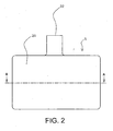
- Impeller 21' which similarly rotates without contacting the housing 20.
- Impeller 21' is substantially the same as impeller 21, except that there is no groove 38 for hydrodynamic bearing provided on a surface of the impeller 21' at the side of the rotor 31.
- impeller 21' includes a plurality of steps 200 for hydrodynamic bearing at the side of the rotor 31, and the inner surface of the housing 20 at the side of the rotor 31 is substantially smooth.
- the impeller 21' rotates at a position spaced at a short distance from the inner surface of the housing 20 without contacting the inner surface thereof, thus providing a blood passage between the lower surface of the impeller 21' and the inner surface of the housing 20.
- the functioning and operation of a centrifugal fluid pump apparatus having the impeller 21' is identical to that described above, except that the steps 200 define the hydrodynamic bearing rather than the grooves 38.
Landscapes
- Engineering & Computer Science (AREA)
- Health & Medical Sciences (AREA)
- Heart & Thoracic Surgery (AREA)
- Mechanical Engineering (AREA)
- Veterinary Medicine (AREA)
- Biomedical Technology (AREA)
- Hematology (AREA)
- Life Sciences & Earth Sciences (AREA)
- Animal Behavior & Ethology (AREA)
- General Health & Medical Sciences (AREA)
- Public Health (AREA)
- Cardiology (AREA)
- Anesthesiology (AREA)
- General Engineering & Computer Science (AREA)
- Physics & Mathematics (AREA)
- Fluid Mechanics (AREA)
- Electromagnetism (AREA)
- Structures Of Non-Positive Displacement Pumps (AREA)
- External Artificial Organs (AREA)
- Control Of Non-Positive-Displacement Pumps (AREA)
- Sliding-Contact Bearings (AREA)
- Magnetic Bearings And Hydrostatic Bearings (AREA)
- Lubrication Of Internal Combustion Engines (AREA)
- Reciprocating Pumps (AREA)
Abstract
Description
Claims (15)
- A centrifugal fluid pump apparatus comprising a pump body in which an impeller rotates without contacting a housing; and a control mechanism for said pump body,
said pump body including:wherein said emergency impeller rotation function has:said housing having a blood inlet port and a blood outlet port;a centrifugal pump section including an impeller having a first magnetic material and a second magnetic material and rotating in said housing to feed a fluid by a centrifugal force generated during its rotation;an impeller rotational torque generation section including a rotor having a magnet for attracting said first magnetic material of said impeller and a motor for rotating said rotor;an impeller position control section having an electromagnet for attracting said second magnetic material of said impeller;a position sensor for detecting a position of said impeller; andhydrodynamic bearing means provided on an inner surface of said housing at a side of said rotor or on a surface of said impeller at a side of said rotor, said control mechanism comprising:a position sensor output monitoring function or an electromagnet current monitoring function;a motor current monitoring function;a failure detection function for determining a failure of the sensor by using said position sensor output monitoring function or a failure of the electromagnet by using said electromagnet current monitoring function; andan emergency impeller rotation function operating when said failure detection function detects the failure of the sensor or the failure of the electromagnet to rotate said impeller by utilizing said hydrodynamic bearing means without substantial contact between said impeller and said housing,rotation termination function of terminating power to the motor and the electromagnet when the failure detection function detects a failure to thereby terminate rotation of the rotor and the impeller;impeller magnetic counterforce application function to apply a current to the electromagnet sufficient to overcome the magnetic coupling force of the rotor to the impeller caused by the magnet;hydrodynamic levitation control detection function of detecting hydraulic bearing coupling and thereby magnetic rotational coupling of the impeller and the rotor under hydraulic bearing conditions by using a motor current monitored by the motor current monitoring function;motor speed control function for increasing the motor speed and hence the impeller rotation speed up to a predetermined value after the hydrodynamic levitation control detection function detects that the hydraulic bearing coupling between the impeller and the rotor has been made; andimpeller magnetic counterforce termination function to terminate current to the electromagnet once the predetermined impeller rotation speed is reached. - A centrifugal fluid pump apparatus according to claim 1, wherein said control mechanism has said position sensor output monitoring function and said electromagnet current monitoring function and said failure detection function can determine the failure of the sensor and the failure of the electromagnet.
- A centrifugal fluid pump apparatus according to claim 1, further comprising a sensor circuit for said sensor, wherein said sensor circuit has a function of generating an output having a predetermined value exceeding a normal level when said sensor has disconnection, and said failure detection function determines whether said sensor has a failure, based on an output of said sensor monitored by said sensor output monitoring function.
- A centrifugal fluid pump apparatus according to claim 1, further comprising an electromagnet circuit for said electromagnet, wherein said electromagnet circuit is not energized when said electromagnet has disconnection, and said failure detection function determines that said electromagnet has a failure when said electromagnet current monitoring function monitors that electric current is not applied to said electromagnet circuit.
- A centrifugal fluid pump apparatus according to claim 1, wherein when said failure detection function detects a failure, said emergency impeller rotation function allows said impeller to rotate by balancing the magnetic coupling force between the magnet of said rotor and said impeller and the counterforce generated by said electromagnet..
- A centrifugal fluid pump apparatus according to claim 1, wherein said hydrodynamic bearing means includes at least one groove provided on the inner surface of said housing at a side of said rotor.
- A centrifugal fluid pump apparatus according to claim 1, wherein said hydrodynamic bearing means includes at least one groove provided on the surface of said impeller at a side of said rotor.
- A centrifugal fluid pump apparatus according to claim 1, wherein said hydrodynamic bearing means includes a plurality of steps provided on the surface of said impeller at a side of said rotor.
- A centrifugal fluid pump apparatus according to claim 1, wherein said impeller magnetic counterforce application function comprises applying a first duration current to the electromagnet to create a counterforce and attempting to rotate the impeller by applying a predetermined voltage to the motor.
- A centrifugal fluid pump apparatus according to claim 9, wherein when the motor fails to achieve rotation of the impeller after the first attempt, said impeller magnetic counterforce application function further comprises applying a second duration current to the electromagnet to create the counterforce and attempting to rotate the impeller by applying the predetermined voltage to the motor, wherein said second duration current is greater than said first duration current such that the counterforce created with said second duration current is greater than the counterforce created with said first duration current.
- A centrifugal fluid pump apparatus according to claim 10, wherein said second duration current is greater than said first duration current by a predetermined step value.
- A centrifugal fluid pump apparatus according to claim 11, wherein when the motor fails to achieve rotation of the impeller after the first and second attempts, said impeller magnetic counterforce application function further comprises repeatedly applying an increased duration current to the electromagnet to create the counterforce and attempting to rotate the impeller by applying the predetermined voltage to the motor, said increased duration current being repeatedly increased by the predetermined step value until one of rotation of the impeller is achieved or said increased duration current reaches a predetermined maximum value.
- A centrifugal fluid pump apparatus according to claim 12, wherein said first duration current is a 10% on time duty cycle.
- A centrifugal fluid pump apparatus according to claim 12, wherein the predetermined step value is 1%.
- A centrifugal fluid pump apparatus according to claim 12, wherein the predetermined maximum value of said increased duration current is approximately 20% on time.
Applications Claiming Priority (2)
| Application Number | Priority Date | Filing Date | Title |
|---|---|---|---|
| US613068 | 2003-07-07 | ||
| US10/613,068 US7128538B2 (en) | 2003-07-07 | 2003-07-07 | Centrifugal fluid pump apparatus |
Publications (3)
| Publication Number | Publication Date |
|---|---|
| EP1495773A2 true EP1495773A2 (en) | 2005-01-12 |
| EP1495773A3 EP1495773A3 (en) | 2006-11-29 |
| EP1495773B1 EP1495773B1 (en) | 2009-02-18 |
Family
ID=33452641
Family Applications (1)
| Application Number | Title | Priority Date | Filing Date |
|---|---|---|---|
| EP04015954A Expired - Lifetime EP1495773B1 (en) | 2003-07-07 | 2004-07-07 | Centrifugal fluid pump apparatus |
Country Status (5)
| Country | Link |
|---|---|
| US (1) | US7128538B2 (en) |
| EP (1) | EP1495773B1 (en) |
| JP (1) | JP4308723B2 (en) |
| AT (1) | ATE422914T1 (en) |
| DE (1) | DE602004019474D1 (en) |
Cited By (30)
| Publication number | Priority date | Publication date | Assignee | Title |
|---|---|---|---|---|
| EP1598087A3 (en) * | 2004-03-24 | 2007-04-25 | Terumo Kabushiki Kaisha | Blood pump apparatus |
| WO2008101687A3 (en) * | 2007-02-21 | 2008-10-23 | Grundfos Management As | Pump unit |
| EP2372160A4 (en) * | 2008-12-08 | 2013-01-30 | Ntn Toyo Bearing Co Ltd | CENTRIFUGAL PUMPING DEVICE |
| EP2719403A1 (en) * | 2012-10-12 | 2014-04-16 | Abiomed Europe GmbH | Centrifugal blood pump |
| US8821365B2 (en) | 2009-07-29 | 2014-09-02 | Thoratec Corporation | Rotation drive device and centrifugal pump apparatus using the same |
| US8827661B2 (en) | 2008-06-23 | 2014-09-09 | Thoratec Corporation | Blood pump apparatus |
| US9068572B2 (en) | 2010-07-12 | 2015-06-30 | Thoratec Corporation | Centrifugal pump apparatus |
| US9133854B2 (en) | 2010-03-26 | 2015-09-15 | Thoratec Corporation | Centrifugal blood pump device |
| US9132215B2 (en) | 2010-02-16 | 2015-09-15 | Thoratee Corporation | Centrifugal pump apparatus |
| US9366261B2 (en) | 2012-01-18 | 2016-06-14 | Thoratec Corporation | Centrifugal pump device |
| US9371826B2 (en) | 2013-01-24 | 2016-06-21 | Thoratec Corporation | Impeller position compensation using field oriented control |
| US9381285B2 (en) | 2009-03-05 | 2016-07-05 | Thoratec Corporation | Centrifugal pump apparatus |
| US9382908B2 (en) | 2010-09-14 | 2016-07-05 | Thoratec Corporation | Centrifugal pump apparatus |
| US9410549B2 (en) | 2009-03-06 | 2016-08-09 | Thoratec Corporation | Centrifugal pump apparatus |
| US9556873B2 (en) | 2013-02-27 | 2017-01-31 | Tc1 Llc | Startup sequence for centrifugal pump with levitated impeller |
| US9587641B2 (en) | 2012-04-11 | 2017-03-07 | Waterous Company | Integrated reciprocating primer drive arrangement |
| US9623161B2 (en) | 2014-08-26 | 2017-04-18 | Tc1 Llc | Blood pump and method of suction detection |
| US9713663B2 (en) | 2013-04-30 | 2017-07-25 | Tc1 Llc | Cardiac pump with speed adapted for ventricle unloading |
| US9827357B2 (en) | 2011-12-03 | 2017-11-28 | Indiana University Research And Technology Corporation | Cavopulmonary viscous impeller assist device and method |
| US9850906B2 (en) | 2011-03-28 | 2017-12-26 | Tc1 Llc | Rotation drive device and centrifugal pump apparatus employing same |
| US10052420B2 (en) | 2013-04-30 | 2018-08-21 | Tc1 Llc | Heart beat identification and pump speed synchronization |
| US10117983B2 (en) | 2015-11-16 | 2018-11-06 | Tc1 Llc | Pressure/flow characteristic modification of a centrifugal pump in a ventricular assist device |
| US10166318B2 (en) | 2015-02-12 | 2019-01-01 | Tc1 Llc | System and method for controlling the position of a levitated rotor |
| WO2018187576A3 (en) * | 2017-04-05 | 2019-01-10 | Bivacor Inc. | Heart pump drive and bearing |
| US10245361B2 (en) | 2015-02-13 | 2019-04-02 | Tc1 Llc | Impeller suspension mechanism for heart pump |
| US10371152B2 (en) | 2015-02-12 | 2019-08-06 | Tc1 Llc | Alternating pump gaps |
| US10506935B2 (en) | 2015-02-11 | 2019-12-17 | Tc1 Llc | Heart beat identification and pump speed synchronization |
| CN110671341A (en) * | 2019-11-04 | 2020-01-10 | 江苏科技大学 | Diagnosis method and device for centrifugal pump impeller damage based on sensorless monitoring technology |
| US10543301B2 (en) | 2016-01-06 | 2020-01-28 | Bivacor Inc. | Heart pump |
| CN110848165A (en) * | 2019-11-04 | 2020-02-28 | 江苏科技大学 | Fault diagnosis method and device for centrifugal pump mechanical seal based on sensorless monitoring technology |
Families Citing this family (56)
| Publication number | Priority date | Publication date | Assignee | Title |
|---|---|---|---|---|
| JP4866704B2 (en) * | 2006-10-26 | 2012-02-01 | 独立行政法人産業技術総合研究所 | Artificial heart pump with hydrodynamic bearing |
| JP4787726B2 (en) * | 2006-11-28 | 2011-10-05 | テルモ株式会社 | Sensorless magnetic bearing blood pump device |
| US9044535B2 (en) * | 2007-08-07 | 2015-06-02 | Terumo Cardiovascular Systems Corp. | Extracorporeal blood pump with disposable pump head portion having magnetically levitated impeller |
| DE102011075097A1 (en) * | 2011-05-02 | 2012-11-08 | Krones Aktiengesellschaft | Device for moving a fluid |
| US9511178B2 (en) | 2012-07-09 | 2016-12-06 | Medtronic, Inc. | Reducing centrifugal pump bearing wear through dynamic magnetic coupling |
| US9127680B2 (en) * | 2013-04-05 | 2015-09-08 | Thoratec Corporation | Verification of magnetic balance for magnetically levitated impeller |
| WO2014187466A1 (en) * | 2013-05-23 | 2014-11-27 | Rheinisch-Westfälische Technische Hochschule Aachen | Impeller of a centrifugal pump apparatus |
| US9623162B2 (en) * | 2014-11-05 | 2017-04-18 | Reliantheart Inc. | Implantable blood pump |
| KR101766959B1 (en) * | 2015-07-09 | 2017-08-09 | 정유철 | Pump apparatus having driving state displaying function |
| EP3135933B1 (en) * | 2015-08-25 | 2019-05-01 | ReinHeart GmbH | Active magnetic bearing |
| CN110944689B (en) | 2017-06-07 | 2022-12-09 | 施菲姆德控股有限责任公司 | Intravascular fluid movement devices, systems, and methods of use |
| US11511103B2 (en) | 2017-11-13 | 2022-11-29 | Shifamed Holdings, Llc | Intravascular fluid movement devices, systems, and methods of use |
| DE102018201030B4 (en) | 2018-01-24 | 2025-10-16 | Kardion Gmbh | Magnetic dome element with magnetic bearing function |
| EP4085965A1 (en) | 2018-02-01 | 2022-11-09 | Shifamed Holdings, LLC | Intravascular blood pumps and methods of use and manufacture |
| JP7050534B2 (en) * | 2018-03-08 | 2022-04-08 | テルモ株式会社 | Pump device |
| DE102018207611A1 (en) | 2018-05-16 | 2019-11-21 | Kardion Gmbh | Rotor bearing system |
| DE102018207575A1 (en) | 2018-05-16 | 2019-11-21 | Kardion Gmbh | Magnetic face turning coupling for the transmission of torques |
| DE102018208539A1 (en) | 2018-05-30 | 2019-12-05 | Kardion Gmbh | A motor housing module for sealing an engine compartment of a motor of a cardiac assist system and cardiac assistance system and method for mounting a cardiac assist system |
| DE102018208541A1 (en) | 2018-05-30 | 2019-12-05 | Kardion Gmbh | Axial pump for a cardiac assist system and method of making an axial pump for a cardiac assist system |
| DE102018208550A1 (en) | 2018-05-30 | 2019-12-05 | Kardion Gmbh | A lead device for directing blood flow to a cardiac assist system, cardiac assist system, and method of making a lead device |
| DE102018208538A1 (en) | 2018-05-30 | 2019-12-05 | Kardion Gmbh | Intravascular blood pump and process for the production of electrical conductors |
| DE102018208549A1 (en) | 2018-05-30 | 2019-12-05 | Kardion Gmbh | Electronic module for a cardiac assist system and method for manufacturing an electronic module for a cardiac assist system |
| DE102018208936A1 (en) | 2018-06-06 | 2019-12-12 | Kardion Gmbh | Determining device and method for determining a viscosity of a fluid |
| DE102018208870A1 (en) | 2018-06-06 | 2019-12-12 | Kardion Gmbh | A method of determining a fluid volume flow through an implanted vascular support system |
| DE102018208913A1 (en) | 2018-06-06 | 2019-12-12 | Kardion Gmbh | A method of operating an implanted ventricular assist device |
| DE102018208892A1 (en) | 2018-06-06 | 2019-12-12 | Kardion Gmbh | A sensor head device for a minimally invasive cardiac assist system and method of manufacturing a sensor head device for a cardiac assist system |
| DE102018208933A1 (en) | 2018-06-06 | 2019-12-12 | Kardion Gmbh | A method of determining a flow rate of fluid flowing through an implanted vascular support system |
| DE102018208945A1 (en) | 2018-06-06 | 2019-12-12 | Kardion Gmbh | An analysis device and method for analyzing a viscosity of a fluid |
| DE102018208899A1 (en) | 2018-06-06 | 2019-12-12 | Kardion Gmbh | A method for determining the speed of sound in a fluid in the region of an implanted vascular support system |
| DE102018208879A1 (en) | 2018-06-06 | 2020-01-30 | Kardion Gmbh | Method for determining a total fluid volume flow in the area of an implanted, vascular support system |
| DE102018208862A1 (en) | 2018-06-06 | 2019-12-12 | Kardion Gmbh | Implantable vascular support system |
| DE102018208929A1 (en) | 2018-06-06 | 2019-12-12 | Kardion Gmbh | A method of determining a flow rate of fluid flowing through an implanted vascular support system |
| DE102018210076A1 (en) * | 2018-06-21 | 2019-12-24 | Kardion Gmbh | Method and device for detecting a state of wear of a cardiac support system, method and device for operating a cardiac support system and cardiac support system |
| DE102018210058A1 (en) | 2018-06-21 | 2019-12-24 | Kardion Gmbh | Stator blade device for guiding the flow of a fluid flowing out of an outlet opening of a heart support system, heart support system with stator blade device, method for operating a stator blade device and manufacturing method |
| DE102018211297A1 (en) | 2018-07-09 | 2020-01-09 | Kardion Gmbh | Cardiac support system and method for monitoring the integrity of a support structure of a cardiac support system |
| DE102018211327A1 (en) | 2018-07-10 | 2020-01-16 | Kardion Gmbh | Impeller for an implantable vascular support system |
| DE102018211328A1 (en) | 2018-07-10 | 2020-01-16 | Kardion Gmbh | Impeller housing for an implantable vascular support system |
| DE102018212153A1 (en) | 2018-07-20 | 2020-01-23 | Kardion Gmbh | Inlet line for a pump unit of a cardiac support system, cardiac support system and method for producing an inlet line for a pump unit of a cardiac support system |
| WO2020028537A1 (en) | 2018-07-31 | 2020-02-06 | Shifamed Holdings, Llc | Intravascaular blood pumps and methods of use |
| WO2020030700A1 (en) | 2018-08-07 | 2020-02-13 | Kardion Gmbh | Bearing device for a heart support system, and method for rinsing a space in a bearing device for a heart support system |
| DE102018213350A1 (en) | 2018-08-08 | 2020-02-13 | Kardion Gmbh | Device and method for monitoring a patient's health |
| AU2019342744B2 (en) * | 2018-09-21 | 2024-07-11 | Abiomed, Inc. | Use of optical fiber sensor as a diagnostic tool in catheter-based medical devices |
| JP7470108B2 (en) | 2018-10-05 | 2024-04-17 | シファメド・ホールディングス・エルエルシー | Intravascular blood pump and method of use |
| WO2021011473A1 (en) | 2019-07-12 | 2021-01-21 | Shifamed Holdings, Llc | Intravascular blood pumps and methods of manufacture and use |
| WO2021016372A1 (en) | 2019-07-22 | 2021-01-28 | Shifamed Holdings, Llc | Intravascular blood pumps with struts and methods of use and manufacture |
| CN110292670B (en) * | 2019-08-20 | 2019-12-03 | 上海微创心力医疗科技有限公司 | Magnetic coupling centrifugal blood pump and its blood pump pedestal, blood pump controller and control method |
| EP4034192B1 (en) | 2019-09-25 | 2025-12-24 | Supira Medical, Inc. | Intravascular blood pump systems and methods of use and control thereof |
| WO2021062260A1 (en) | 2019-09-25 | 2021-04-01 | Shifamed Holdings, Llc | Catheter blood pumps and collapsible blood conduits |
| US12409310B2 (en) | 2019-12-11 | 2025-09-09 | Shifamed Holdings, Llc | Descending aorta and vena cava blood pumps |
| DE102020102474A1 (en) | 2020-01-31 | 2021-08-05 | Kardion Gmbh | Pump for conveying a fluid and method for manufacturing a pump |
| EP4210809A1 (en) | 2020-09-14 | 2023-07-19 | Kardion GmbH | Cardiovascular support pump having an impeller with a variable flow area |
| CN112145553B (en) * | 2020-09-22 | 2021-08-10 | 珠海格力电器股份有限公司 | Magnetic suspension bearing system, control method and device thereof and storage medium |
| US12502524B2 (en) | 2021-12-03 | 2025-12-23 | Kardion Gmbh | Cardiac pump with optical fiber for laser doppler |
| CN114368845A (en) * | 2021-12-09 | 2022-04-19 | 徐州市正联机电设备有限公司 | Fixing device for preventing impeller from slipping for ecological restoration aerator |
| CN114810623B (en) * | 2022-04-16 | 2023-09-22 | 江苏大学流体机械温岭研究院 | A method and device for health monitoring and evaluation of vane pumps based on Mahalanobis distance |
| CN117065202B (en) * | 2023-08-21 | 2026-01-06 | 上海东心生物医疗科技有限公司 | Suspended blood pump with control electromagnetic bearing |
Family Cites Families (14)
| Publication number | Priority date | Publication date | Assignee | Title |
|---|---|---|---|---|
| US5211546A (en) * | 1990-05-29 | 1993-05-18 | Nu-Tech Industries, Inc. | Axial flow blood pump with hydrodynamically suspended rotor |
| US5575630A (en) * | 1995-08-08 | 1996-11-19 | Kyocera Corporation | Blood pump having magnetic attraction |
| US5947703A (en) | 1996-01-31 | 1999-09-07 | Ntn Corporation | Centrifugal blood pump assembly |
| JPH09313600A (en) * | 1996-05-28 | 1997-12-09 | Terumo Corp | Centrifugal liquid pump |
| US6071093A (en) | 1996-10-18 | 2000-06-06 | Abiomed, Inc. | Bearingless blood pump and electronic drive system |
| EP0900572B1 (en) * | 1997-09-04 | 2005-01-12 | Levitronix LLC | Centrifugal pump |
| ATE289008T1 (en) * | 1998-08-21 | 2005-02-15 | Cp Pumpen Ag | MAGNETIC COUPLED CENTRIFUGAL PUMP |
| DE29821565U1 (en) * | 1998-12-02 | 2000-06-15 | Impella Cardiotechnik AG, 52074 Aachen | Bearingless blood pump |
| CA2260171A1 (en) | 1999-01-22 | 2000-07-22 | Kriton Medical, Inc. | Sealless blood pump with means for avoiding thrombus formation |
| EP1070510B1 (en) | 1999-07-23 | 2007-01-03 | Terumo Kabushiki Kaisha | Centrifugal fluid pump assembly |
| US6227817B1 (en) * | 1999-09-03 | 2001-05-08 | Magnetic Moments, Llc | Magnetically-suspended centrifugal blood pump |
| DE60006926T2 (en) * | 1999-12-27 | 2004-06-17 | Terumo K.K. | Liquid pump with magnetically suspended impeller |
| US6547530B2 (en) * | 2000-05-19 | 2003-04-15 | Ntn Corporation | Fluid pump apparatus |
| US6589030B2 (en) * | 2000-06-20 | 2003-07-08 | Ntn Corporation | Magnetically levitated pump apparatus |
-
2003
- 2003-07-07 US US10/613,068 patent/US7128538B2/en not_active Expired - Fee Related
-
2004
- 2004-07-06 JP JP2004199714A patent/JP4308723B2/en not_active Expired - Fee Related
- 2004-07-07 DE DE602004019474T patent/DE602004019474D1/en not_active Expired - Lifetime
- 2004-07-07 AT AT04015954T patent/ATE422914T1/en not_active IP Right Cessation
- 2004-07-07 EP EP04015954A patent/EP1495773B1/en not_active Expired - Lifetime
Cited By (62)
| Publication number | Priority date | Publication date | Assignee | Title |
|---|---|---|---|---|
| US7748964B2 (en) | 2004-03-24 | 2010-07-06 | Terumo Kabushiki Kaisha | Blood pump apparatus |
| US8430652B2 (en) | 2004-03-24 | 2013-04-30 | Terumo Kabushiki Kaisha | Blood pump apparatus |
| EP1598087A3 (en) * | 2004-03-24 | 2007-04-25 | Terumo Kabushiki Kaisha | Blood pump apparatus |
| WO2008101687A3 (en) * | 2007-02-21 | 2008-10-23 | Grundfos Management As | Pump unit |
| US10443601B2 (en) | 2007-02-21 | 2019-10-15 | Grundfos Management A/S | Pump unit having an elctric drive motor and electronic control device |
| US9109601B2 (en) | 2008-06-23 | 2015-08-18 | Thoratec Corporation | Blood pump apparatus |
| US8827661B2 (en) | 2008-06-23 | 2014-09-09 | Thoratec Corporation | Blood pump apparatus |
| EP2372160A4 (en) * | 2008-12-08 | 2013-01-30 | Ntn Toyo Bearing Co Ltd | CENTRIFUGAL PUMPING DEVICE |
| US9067005B2 (en) | 2008-12-08 | 2015-06-30 | Thoratec Corporation | Centrifugal pump apparatus |
| US9381285B2 (en) | 2009-03-05 | 2016-07-05 | Thoratec Corporation | Centrifugal pump apparatus |
| US9410549B2 (en) | 2009-03-06 | 2016-08-09 | Thoratec Corporation | Centrifugal pump apparatus |
| US8821365B2 (en) | 2009-07-29 | 2014-09-02 | Thoratec Corporation | Rotation drive device and centrifugal pump apparatus using the same |
| US9132215B2 (en) | 2010-02-16 | 2015-09-15 | Thoratee Corporation | Centrifugal pump apparatus |
| US9133854B2 (en) | 2010-03-26 | 2015-09-15 | Thoratec Corporation | Centrifugal blood pump device |
| US9068572B2 (en) | 2010-07-12 | 2015-06-30 | Thoratec Corporation | Centrifugal pump apparatus |
| US9638202B2 (en) | 2010-09-14 | 2017-05-02 | Tc1 Llc | Centrifugal pump apparatus |
| US9382908B2 (en) | 2010-09-14 | 2016-07-05 | Thoratec Corporation | Centrifugal pump apparatus |
| US9850906B2 (en) | 2011-03-28 | 2017-12-26 | Tc1 Llc | Rotation drive device and centrifugal pump apparatus employing same |
| US9827357B2 (en) | 2011-12-03 | 2017-11-28 | Indiana University Research And Technology Corporation | Cavopulmonary viscous impeller assist device and method |
| US10744245B2 (en) | 2011-12-03 | 2020-08-18 | Indiana University Research And Technology Corporation | Cavopulmonary viscous impeller assist device and method |
| US9366261B2 (en) | 2012-01-18 | 2016-06-14 | Thoratec Corporation | Centrifugal pump device |
| US9587641B2 (en) | 2012-04-11 | 2017-03-07 | Waterous Company | Integrated reciprocating primer drive arrangement |
| US12196210B2 (en) | 2012-10-12 | 2025-01-14 | Abiomed Europe Gmbh | Centrifugal blood pump with hydrodynamic bearing |
| EP2719403A1 (en) * | 2012-10-12 | 2014-04-16 | Abiomed Europe GmbH | Centrifugal blood pump |
| WO2014057087A1 (en) * | 2012-10-12 | 2014-04-17 | Abiomed Europe Gmbh | Centrifugal blood pump |
| US11092158B2 (en) | 2012-10-12 | 2021-08-17 | Abiomed Europe Gmbh | Centrifugal blood pump with hydrodynamic bearing |
| US9709061B2 (en) | 2013-01-24 | 2017-07-18 | Tc1 Llc | Impeller position compensation using field oriented control |
| US9371826B2 (en) | 2013-01-24 | 2016-06-21 | Thoratec Corporation | Impeller position compensation using field oriented control |
| US9556873B2 (en) | 2013-02-27 | 2017-01-31 | Tc1 Llc | Startup sequence for centrifugal pump with levitated impeller |
| US9713663B2 (en) | 2013-04-30 | 2017-07-25 | Tc1 Llc | Cardiac pump with speed adapted for ventricle unloading |
| US11724094B2 (en) | 2013-04-30 | 2023-08-15 | Tc1 Llc | Cardiac pump with speed adapted for ventricle unloading |
| US12343517B2 (en) | 2013-04-30 | 2025-07-01 | Tc1 Llc | Cardiac pump with speed adapted for ventricle unloading |
| US10052420B2 (en) | 2013-04-30 | 2018-08-21 | Tc1 Llc | Heart beat identification and pump speed synchronization |
| US10456513B2 (en) | 2013-04-30 | 2019-10-29 | Tc1 Llc | Cardiac pump with speed adapted for ventricle unloading |
| US10980928B2 (en) | 2013-04-30 | 2021-04-20 | Tc1 Llc | Cardiac pump with speed adapted for ventricle unloading |
| US9623161B2 (en) | 2014-08-26 | 2017-04-18 | Tc1 Llc | Blood pump and method of suction detection |
| US11712167B2 (en) | 2015-02-11 | 2023-08-01 | Tc1 Llc | Heart beat identification and pump speed synchronization |
| US10506935B2 (en) | 2015-02-11 | 2019-12-17 | Tc1 Llc | Heart beat identification and pump speed synchronization |
| US10856748B2 (en) | 2015-02-11 | 2020-12-08 | Tc1 Llc | Heart beat identification and pump speed synchronization |
| US11015605B2 (en) | 2015-02-12 | 2021-05-25 | Tc1 Llc | Alternating pump gaps |
| US11781551B2 (en) | 2015-02-12 | 2023-10-10 | Tc1 Llc | Alternating pump gaps |
| US10874782B2 (en) | 2015-02-12 | 2020-12-29 | Tc1 Llc | System and method for controlling the position of a levitated rotor |
| US12297836B2 (en) | 2015-02-12 | 2025-05-13 | Tc1 Llc | Alternating pump gaps |
| US12285598B2 (en) | 2015-02-12 | 2025-04-29 | Tc1 Llc | System and method for controlling the position of a levitated rotor |
| US10166318B2 (en) | 2015-02-12 | 2019-01-01 | Tc1 Llc | System and method for controlling the position of a levitated rotor |
| US10371152B2 (en) | 2015-02-12 | 2019-08-06 | Tc1 Llc | Alternating pump gaps |
| US11724097B2 (en) | 2015-02-12 | 2023-08-15 | Tc1 Llc | System and method for controlling the position of a levitated rotor |
| US10245361B2 (en) | 2015-02-13 | 2019-04-02 | Tc1 Llc | Impeller suspension mechanism for heart pump |
| US10117983B2 (en) | 2015-11-16 | 2018-11-06 | Tc1 Llc | Pressure/flow characteristic modification of a centrifugal pump in a ventricular assist device |
| US11639722B2 (en) | 2015-11-16 | 2023-05-02 | Tc1 Llc | Pressure/flow characteristic modification of a centrifugal pump in a ventricular assist device |
| US11826558B2 (en) | 2016-01-06 | 2023-11-28 | Bivacor Inc. | Heart pump with impeller rotational speed control |
| US11278712B2 (en) | 2016-01-06 | 2022-03-22 | Bivacor Inc. | Heart pump with impeller rotational speed control |
| US10960200B2 (en) | 2016-01-06 | 2021-03-30 | Bivacor Inc. | Heart pump with impeller axial position control |
| US10543301B2 (en) | 2016-01-06 | 2020-01-28 | Bivacor Inc. | Heart pump |
| US11154703B2 (en) | 2016-01-06 | 2021-10-26 | Bivacor Inc. | Heart pump |
| US11833341B2 (en) | 2016-01-06 | 2023-12-05 | Bivacor Inc. | Heart pump |
| US11654274B2 (en) | 2017-04-05 | 2023-05-23 | Bivacor Inc. | Heart pump drive and bearing |
| WO2018187576A3 (en) * | 2017-04-05 | 2019-01-10 | Bivacor Inc. | Heart pump drive and bearing |
| AU2018250273B2 (en) * | 2017-04-05 | 2023-06-08 | Bivacor Inc. | Heart pump drive and bearing |
| AU2018250273A8 (en) * | 2017-04-05 | 2023-03-23 | Bivacor Inc. | Heart pump drive and bearing |
| CN110848165A (en) * | 2019-11-04 | 2020-02-28 | 江苏科技大学 | Fault diagnosis method and device for centrifugal pump mechanical seal based on sensorless monitoring technology |
| CN110671341A (en) * | 2019-11-04 | 2020-01-10 | 江苏科技大学 | Diagnosis method and device for centrifugal pump impeller damage based on sensorless monitoring technology |
Also Published As
| Publication number | Publication date |
|---|---|
| DE602004019474D1 (en) | 2009-04-02 |
| EP1495773A3 (en) | 2006-11-29 |
| ATE422914T1 (en) | 2009-03-15 |
| US7128538B2 (en) | 2006-10-31 |
| JP4308723B2 (en) | 2009-08-05 |
| EP1495773B1 (en) | 2009-02-18 |
| JP2005028137A (en) | 2005-02-03 |
| US20050008496A1 (en) | 2005-01-13 |
Similar Documents
| Publication | Publication Date | Title |
|---|---|---|
| US7128538B2 (en) | Centrifugal fluid pump apparatus | |
| EP1327455B1 (en) | Centrifugal fluid pump with failure correction | |
| US7470246B2 (en) | Centrifugal blood pump apparatus | |
| JP4456857B2 (en) | Centrifugal blood pump device | |
| EP1598087B1 (en) | blood pump with hydrodynamic bearing | |
| JP4472610B2 (en) | Centrifugal blood pump device | |
| US6398506B1 (en) | Centrifugal fluid pump and control device for operating the same | |
| JP4787726B2 (en) | Sensorless magnetic bearing blood pump device | |
| EP2693609B1 (en) | Rotation and drive device and centrifugal pump device using same | |
| EP2461465B1 (en) | Rotation drive device and centrifugal pump device | |
| JP4472612B2 (en) | Centrifugal blood pump device | |
| US8596999B2 (en) | Disposable centrifugal blood pump with magnetic coupling | |
| JP4340178B2 (en) | Centrifugal blood pump device | |
| JP2006525460A (en) | Fluid pump | |
| JP3729889B2 (en) | Magnetic bearing pump | |
| JP2006167142A (en) | Blood pump system | |
| JP2001041166A (en) | Centrifugal liquid pump device | |
| JP4685227B2 (en) | Magnetic levitation pump | |
| JP2002021773A (en) | Centrifugal liquid pump device | |
| JP2005287598A (en) | Blood pump system | |
| JP5015985B2 (en) | Centrifugal blood pump device |
Legal Events
| Date | Code | Title | Description |
|---|---|---|---|
| PUAI | Public reference made under article 153(3) epc to a published international application that has entered the european phase |
Free format text: ORIGINAL CODE: 0009012 |
|
| AK | Designated contracting states |
Kind code of ref document: A2 Designated state(s): AT BE BG CH CY CZ DE DK EE ES FI FR GB GR HU IE IT LI LU MC NL PL PT RO SE SI SK TR |
|
| AX | Request for extension of the european patent |
Extension state: AL HR LT LV MK |
|
| 17P | Request for examination filed |
Effective date: 20050621 |
|
| PUAL | Search report despatched |
Free format text: ORIGINAL CODE: 0009013 |
|
| AK | Designated contracting states |
Kind code of ref document: A3 Designated state(s): AT BE BG CH CY CZ DE DK EE ES FI FR GB GR HU IE IT LI LU MC NL PL PT RO SE SI SK TR |
|
| AX | Request for extension of the european patent |
Extension state: AL HR LT LV MK |
|
| RIC1 | Information provided on ipc code assigned before grant |
Ipc: A61M 1/10 20060101AFI20041111BHEP Ipc: F04D 1/00 20060101ALI20061025BHEP Ipc: F04D 15/02 20060101ALI20061025BHEP Ipc: F04D 15/00 20060101ALI20061025BHEP Ipc: F04D 29/04 20060101ALI20061025BHEP Ipc: F04D 29/22 20060101ALI20061025BHEP |
|
| AKX | Designation fees paid |
Designated state(s): AT BE BG CH CY CZ DE DK EE ES FI FR GB GR HU IE IT LI LU MC NL PL PT RO SE SI SK TR |
|
| 17Q | First examination report despatched |
Effective date: 20070807 |
|
| GRAP | Despatch of communication of intention to grant a patent |
Free format text: ORIGINAL CODE: EPIDOSNIGR1 |
|
| GRAS | Grant fee paid |
Free format text: ORIGINAL CODE: EPIDOSNIGR3 |
|
| GRAA | (expected) grant |
Free format text: ORIGINAL CODE: 0009210 |
|
| AK | Designated contracting states |
Kind code of ref document: B1 Designated state(s): AT BE BG CH CY CZ DE DK EE ES FI FR GB GR HU IE IT LI LU MC NL PL PT RO SE SI SK TR |
|
| REG | Reference to a national code |
Ref country code: GB Ref legal event code: FG4D |
|
| REG | Reference to a national code |
Ref country code: CH Ref legal event code: EP |
|
| REG | Reference to a national code |
Ref country code: IE Ref legal event code: FG4D |
|
| REF | Corresponds to: |
Ref document number: 602004019474 Country of ref document: DE Date of ref document: 20090402 Kind code of ref document: P |
|
| PG25 | Lapsed in a contracting state [announced via postgrant information from national office to epo] |
Ref country code: FI Free format text: LAPSE BECAUSE OF FAILURE TO SUBMIT A TRANSLATION OF THE DESCRIPTION OR TO PAY THE FEE WITHIN THE PRESCRIBED TIME-LIMIT Effective date: 20090218 Ref country code: SI Free format text: LAPSE BECAUSE OF FAILURE TO SUBMIT A TRANSLATION OF THE DESCRIPTION OR TO PAY THE FEE WITHIN THE PRESCRIBED TIME-LIMIT Effective date: 20090218 Ref country code: ES Free format text: LAPSE BECAUSE OF FAILURE TO SUBMIT A TRANSLATION OF THE DESCRIPTION OR TO PAY THE FEE WITHIN THE PRESCRIBED TIME-LIMIT Effective date: 20090529 Ref country code: NL Free format text: LAPSE BECAUSE OF FAILURE TO SUBMIT A TRANSLATION OF THE DESCRIPTION OR TO PAY THE FEE WITHIN THE PRESCRIBED TIME-LIMIT Effective date: 20090218 |
|
| NLV1 | Nl: lapsed or annulled due to failure to fulfill the requirements of art. 29p and 29m of the patents act | ||
| PG25 | Lapsed in a contracting state [announced via postgrant information from national office to epo] |
Ref country code: AT Free format text: LAPSE BECAUSE OF FAILURE TO SUBMIT A TRANSLATION OF THE DESCRIPTION OR TO PAY THE FEE WITHIN THE PRESCRIBED TIME-LIMIT Effective date: 20090218 Ref country code: SE Free format text: LAPSE BECAUSE OF FAILURE TO SUBMIT A TRANSLATION OF THE DESCRIPTION OR TO PAY THE FEE WITHIN THE PRESCRIBED TIME-LIMIT Effective date: 20090518 Ref country code: PL Free format text: LAPSE BECAUSE OF FAILURE TO SUBMIT A TRANSLATION OF THE DESCRIPTION OR TO PAY THE FEE WITHIN THE PRESCRIBED TIME-LIMIT Effective date: 20090218 |
|
| PG25 | Lapsed in a contracting state [announced via postgrant information from national office to epo] |
Ref country code: BE Free format text: LAPSE BECAUSE OF FAILURE TO SUBMIT A TRANSLATION OF THE DESCRIPTION OR TO PAY THE FEE WITHIN THE PRESCRIBED TIME-LIMIT Effective date: 20090218 |
|
| PG25 | Lapsed in a contracting state [announced via postgrant information from national office to epo] |
Ref country code: PT Free format text: LAPSE BECAUSE OF FAILURE TO SUBMIT A TRANSLATION OF THE DESCRIPTION OR TO PAY THE FEE WITHIN THE PRESCRIBED TIME-LIMIT Effective date: 20090727 Ref country code: EE Free format text: LAPSE BECAUSE OF FAILURE TO SUBMIT A TRANSLATION OF THE DESCRIPTION OR TO PAY THE FEE WITHIN THE PRESCRIBED TIME-LIMIT Effective date: 20090218 Ref country code: CZ Free format text: LAPSE BECAUSE OF FAILURE TO SUBMIT A TRANSLATION OF THE DESCRIPTION OR TO PAY THE FEE WITHIN THE PRESCRIBED TIME-LIMIT Effective date: 20090218 Ref country code: DK Free format text: LAPSE BECAUSE OF FAILURE TO SUBMIT A TRANSLATION OF THE DESCRIPTION OR TO PAY THE FEE WITHIN THE PRESCRIBED TIME-LIMIT Effective date: 20090218 |
|
| PG25 | Lapsed in a contracting state [announced via postgrant information from national office to epo] |
Ref country code: SK Free format text: LAPSE BECAUSE OF FAILURE TO SUBMIT A TRANSLATION OF THE DESCRIPTION OR TO PAY THE FEE WITHIN THE PRESCRIBED TIME-LIMIT Effective date: 20090218 Ref country code: RO Free format text: LAPSE BECAUSE OF FAILURE TO SUBMIT A TRANSLATION OF THE DESCRIPTION OR TO PAY THE FEE WITHIN THE PRESCRIBED TIME-LIMIT Effective date: 20090218 |
|
| PLBE | No opposition filed within time limit |
Free format text: ORIGINAL CODE: 0009261 |
|
| STAA | Information on the status of an ep patent application or granted ep patent |
Free format text: STATUS: NO OPPOSITION FILED WITHIN TIME LIMIT |
|
| 26N | No opposition filed |
Effective date: 20091119 |
|
| PG25 | Lapsed in a contracting state [announced via postgrant information from national office to epo] |
Ref country code: BG Free format text: LAPSE BECAUSE OF FAILURE TO SUBMIT A TRANSLATION OF THE DESCRIPTION OR TO PAY THE FEE WITHIN THE PRESCRIBED TIME-LIMIT Effective date: 20090518 |
|
| PG25 | Lapsed in a contracting state [announced via postgrant information from national office to epo] |
Ref country code: MC Free format text: LAPSE BECAUSE OF NON-PAYMENT OF DUE FEES Effective date: 20090731 |
|
| REG | Reference to a national code |
Ref country code: CH Ref legal event code: PL |
|
| REG | Reference to a national code |
Ref country code: IE Ref legal event code: MM4A |
|
| PG25 | Lapsed in a contracting state [announced via postgrant information from national office to epo] |
Ref country code: CH Free format text: LAPSE BECAUSE OF NON-PAYMENT OF DUE FEES Effective date: 20090731 Ref country code: LI Free format text: LAPSE BECAUSE OF NON-PAYMENT OF DUE FEES Effective date: 20090731 |
|
| PG25 | Lapsed in a contracting state [announced via postgrant information from national office to epo] |
Ref country code: IE Free format text: LAPSE BECAUSE OF NON-PAYMENT OF DUE FEES Effective date: 20090707 |
|
| PG25 | Lapsed in a contracting state [announced via postgrant information from national office to epo] |
Ref country code: GR Free format text: LAPSE BECAUSE OF FAILURE TO SUBMIT A TRANSLATION OF THE DESCRIPTION OR TO PAY THE FEE WITHIN THE PRESCRIBED TIME-LIMIT Effective date: 20090519 |
|
| PG25 | Lapsed in a contracting state [announced via postgrant information from national office to epo] |
Ref country code: LU Free format text: LAPSE BECAUSE OF NON-PAYMENT OF DUE FEES Effective date: 20090707 |
|
| PG25 | Lapsed in a contracting state [announced via postgrant information from national office to epo] |
Ref country code: HU Free format text: LAPSE BECAUSE OF FAILURE TO SUBMIT A TRANSLATION OF THE DESCRIPTION OR TO PAY THE FEE WITHIN THE PRESCRIBED TIME-LIMIT Effective date: 20090819 |
|
| PG25 | Lapsed in a contracting state [announced via postgrant information from national office to epo] |
Ref country code: TR Free format text: LAPSE BECAUSE OF FAILURE TO SUBMIT A TRANSLATION OF THE DESCRIPTION OR TO PAY THE FEE WITHIN THE PRESCRIBED TIME-LIMIT Effective date: 20090218 |
|
| PG25 | Lapsed in a contracting state [announced via postgrant information from national office to epo] |
Ref country code: CY Free format text: LAPSE BECAUSE OF FAILURE TO SUBMIT A TRANSLATION OF THE DESCRIPTION OR TO PAY THE FEE WITHIN THE PRESCRIBED TIME-LIMIT Effective date: 20090218 |
|
| PGFP | Annual fee paid to national office [announced via postgrant information from national office to epo] |
Ref country code: FR Payment date: 20130701 Year of fee payment: 10 |
|
| PGFP | Annual fee paid to national office [announced via postgrant information from national office to epo] |
Ref country code: DE Payment date: 20130703 Year of fee payment: 10 |
|
| PGFP | Annual fee paid to national office [announced via postgrant information from national office to epo] |
Ref country code: GB Payment date: 20130703 Year of fee payment: 10 |
|
| PGFP | Annual fee paid to national office [announced via postgrant information from national office to epo] |
Ref country code: IT Payment date: 20130711 Year of fee payment: 10 |
|
| REG | Reference to a national code |
Ref country code: DE Ref legal event code: R119 Ref document number: 602004019474 Country of ref document: DE |
|
| GBPC | Gb: european patent ceased through non-payment of renewal fee |
Effective date: 20140707 |
|
| REG | Reference to a national code |
Ref country code: FR Ref legal event code: ST Effective date: 20150331 |
|
| PG25 | Lapsed in a contracting state [announced via postgrant information from national office to epo] |
Ref country code: DE Free format text: LAPSE BECAUSE OF NON-PAYMENT OF DUE FEES Effective date: 20150203 Ref country code: IT Free format text: LAPSE BECAUSE OF NON-PAYMENT OF DUE FEES Effective date: 20140707 |
|
| REG | Reference to a national code |
Ref country code: DE Ref legal event code: R119 Ref document number: 602004019474 Country of ref document: DE Effective date: 20150203 |
|
| PG25 | Lapsed in a contracting state [announced via postgrant information from national office to epo] |
Ref country code: FR Free format text: LAPSE BECAUSE OF NON-PAYMENT OF DUE FEES Effective date: 20140731 Ref country code: GB Free format text: LAPSE BECAUSE OF NON-PAYMENT OF DUE FEES Effective date: 20140707 |