DE102018208870A1 - A method of determining a fluid volume flow through an implanted vascular support system - Google Patents
A method of determining a fluid volume flow through an implanted vascular support system Download PDFInfo
- Publication number
- DE102018208870A1 DE102018208870A1 DE102018208870.5A DE102018208870A DE102018208870A1 DE 102018208870 A1 DE102018208870 A1 DE 102018208870A1 DE 102018208870 A DE102018208870 A DE 102018208870A DE 102018208870 A1 DE102018208870 A1 DE 102018208870A1
- Authority
- DE
- Germany
- Prior art keywords
- heating element
- support system
- temperature
- temperature sensor
- cannula
- Prior art date
- Legal status (The legal status is an assumption and is not a legal conclusion. Google has not performed a legal analysis and makes no representation as to the accuracy of the status listed.)
- Pending
Links
Images


Classifications
-
- A—HUMAN NECESSITIES
- A61—MEDICAL OR VETERINARY SCIENCE; HYGIENE
- A61M—DEVICES FOR INTRODUCING MEDIA INTO, OR ONTO, THE BODY; DEVICES FOR TRANSDUCING BODY MEDIA OR FOR TAKING MEDIA FROM THE BODY; DEVICES FOR PRODUCING OR ENDING SLEEP OR STUPOR
- A61M60/00—Blood pumps; Devices for mechanical circulatory actuation; Balloon pumps for circulatory assistance
- A61M60/50—Details relating to control
- A61M60/508—Electronic control means, e.g. for feedback regulation
- A61M60/515—Regulation using real-time patient data
- A61M60/523—Regulation using real-time patient data using blood flow data, e.g. from blood flow transducers
-
- A—HUMAN NECESSITIES
- A61—MEDICAL OR VETERINARY SCIENCE; HYGIENE
- A61M—DEVICES FOR INTRODUCING MEDIA INTO, OR ONTO, THE BODY; DEVICES FOR TRANSDUCING BODY MEDIA OR FOR TAKING MEDIA FROM THE BODY; DEVICES FOR PRODUCING OR ENDING SLEEP OR STUPOR
- A61M60/00—Blood pumps; Devices for mechanical circulatory actuation; Balloon pumps for circulatory assistance
- A61M60/10—Location thereof with respect to the patient's body
- A61M60/122—Implantable pumps or pumping devices, i.e. the blood being pumped inside the patient's body
- A61M60/126—Implantable pumps or pumping devices, i.e. the blood being pumped inside the patient's body implantable via, into, inside, in line, branching on, or around a blood vessel
- A61M60/13—Implantable pumps or pumping devices, i.e. the blood being pumped inside the patient's body implantable via, into, inside, in line, branching on, or around a blood vessel by means of a catheter allowing explantation, e.g. catheter pumps temporarily introduced via the vascular system
-
- A—HUMAN NECESSITIES
- A61—MEDICAL OR VETERINARY SCIENCE; HYGIENE
- A61M—DEVICES FOR INTRODUCING MEDIA INTO, OR ONTO, THE BODY; DEVICES FOR TRANSDUCING BODY MEDIA OR FOR TAKING MEDIA FROM THE BODY; DEVICES FOR PRODUCING OR ENDING SLEEP OR STUPOR
- A61M60/00—Blood pumps; Devices for mechanical circulatory actuation; Balloon pumps for circulatory assistance
- A61M60/10—Location thereof with respect to the patient's body
- A61M60/122—Implantable pumps or pumping devices, i.e. the blood being pumped inside the patient's body
- A61M60/165—Implantable pumps or pumping devices, i.e. the blood being pumped inside the patient's body implantable in, on, or around the heart
- A61M60/178—Implantable pumps or pumping devices, i.e. the blood being pumped inside the patient's body implantable in, on, or around the heart drawing blood from a ventricle and returning the blood to the arterial system via a cannula external to the ventricle, e.g. left or right ventricular assist devices
-
- A—HUMAN NECESSITIES
- A61—MEDICAL OR VETERINARY SCIENCE; HYGIENE
- A61M—DEVICES FOR INTRODUCING MEDIA INTO, OR ONTO, THE BODY; DEVICES FOR TRANSDUCING BODY MEDIA OR FOR TAKING MEDIA FROM THE BODY; DEVICES FOR PRODUCING OR ENDING SLEEP OR STUPOR
- A61M60/00—Blood pumps; Devices for mechanical circulatory actuation; Balloon pumps for circulatory assistance
- A61M60/20—Type thereof
- A61M60/205—Non-positive displacement blood pumps
- A61M60/216—Non-positive displacement blood pumps including a rotating member acting on the blood, e.g. impeller
-
- A—HUMAN NECESSITIES
- A61—MEDICAL OR VETERINARY SCIENCE; HYGIENE
- A61M—DEVICES FOR INTRODUCING MEDIA INTO, OR ONTO, THE BODY; DEVICES FOR TRANSDUCING BODY MEDIA OR FOR TAKING MEDIA FROM THE BODY; DEVICES FOR PRODUCING OR ENDING SLEEP OR STUPOR
- A61M60/00—Blood pumps; Devices for mechanical circulatory actuation; Balloon pumps for circulatory assistance
- A61M60/50—Details relating to control
- A61M60/508—Electronic control means, e.g. for feedback regulation
- A61M60/515—Regulation using real-time patient data
-
- A—HUMAN NECESSITIES
- A61—MEDICAL OR VETERINARY SCIENCE; HYGIENE
- A61M—DEVICES FOR INTRODUCING MEDIA INTO, OR ONTO, THE BODY; DEVICES FOR TRANSDUCING BODY MEDIA OR FOR TAKING MEDIA FROM THE BODY; DEVICES FOR PRODUCING OR ENDING SLEEP OR STUPOR
- A61M60/00—Blood pumps; Devices for mechanical circulatory actuation; Balloon pumps for circulatory assistance
- A61M60/50—Details relating to control
- A61M60/508—Electronic control means, e.g. for feedback regulation
- A61M60/538—Regulation using real-time blood pump operational parameter data, e.g. motor current
- A61M60/546—Regulation using real-time blood pump operational parameter data, e.g. motor current of blood flow, e.g. by adapting rotor speed
-
- A—HUMAN NECESSITIES
- A61—MEDICAL OR VETERINARY SCIENCE; HYGIENE
- A61M—DEVICES FOR INTRODUCING MEDIA INTO, OR ONTO, THE BODY; DEVICES FOR TRANSDUCING BODY MEDIA OR FOR TAKING MEDIA FROM THE BODY; DEVICES FOR PRODUCING OR ENDING SLEEP OR STUPOR
- A61M60/00—Blood pumps; Devices for mechanical circulatory actuation; Balloon pumps for circulatory assistance
- A61M60/80—Constructional details other than related to driving
- A61M60/802—Constructional details other than related to driving of non-positive displacement blood pumps
- A61M60/81—Pump housings
- A61M60/816—Sensors arranged on or in the housing, e.g. ultrasound flow sensors
-
- A—HUMAN NECESSITIES
- A61—MEDICAL OR VETERINARY SCIENCE; HYGIENE
- A61M—DEVICES FOR INTRODUCING MEDIA INTO, OR ONTO, THE BODY; DEVICES FOR TRANSDUCING BODY MEDIA OR FOR TAKING MEDIA FROM THE BODY; DEVICES FOR PRODUCING OR ENDING SLEEP OR STUPOR
- A61M60/00—Blood pumps; Devices for mechanical circulatory actuation; Balloon pumps for circulatory assistance
- A61M60/80—Constructional details other than related to driving
- A61M60/855—Constructional details other than related to driving of implantable pumps or pumping devices
- A61M60/857—Implantable blood tubes
-
- A—HUMAN NECESSITIES
- A61—MEDICAL OR VETERINARY SCIENCE; HYGIENE
- A61M—DEVICES FOR INTRODUCING MEDIA INTO, OR ONTO, THE BODY; DEVICES FOR TRANSDUCING BODY MEDIA OR FOR TAKING MEDIA FROM THE BODY; DEVICES FOR PRODUCING OR ENDING SLEEP OR STUPOR
- A61M2205/00—General characteristics of the apparatus
- A61M2205/33—Controlling, regulating or measuring
- A61M2205/3368—Temperature
-
- A—HUMAN NECESSITIES
- A61—MEDICAL OR VETERINARY SCIENCE; HYGIENE
- A61M—DEVICES FOR INTRODUCING MEDIA INTO, OR ONTO, THE BODY; DEVICES FOR TRANSDUCING BODY MEDIA OR FOR TAKING MEDIA FROM THE BODY; DEVICES FOR PRODUCING OR ENDING SLEEP OR STUPOR
- A61M2205/00—General characteristics of the apparatus
- A61M2205/36—General characteristics of the apparatus related to heating or cooling
- A61M2205/3653—General characteristics of the apparatus related to heating or cooling by Joule effect, i.e. electric resistance
-
- A—HUMAN NECESSITIES
- A61—MEDICAL OR VETERINARY SCIENCE; HYGIENE
- A61M—DEVICES FOR INTRODUCING MEDIA INTO, OR ONTO, THE BODY; DEVICES FOR TRANSDUCING BODY MEDIA OR FOR TAKING MEDIA FROM THE BODY; DEVICES FOR PRODUCING OR ENDING SLEEP OR STUPOR
- A61M2205/00—General characteristics of the apparatus
- A61M2205/50—General characteristics of the apparatus with microprocessors or computers
- A61M2205/52—General characteristics of the apparatus with microprocessors or computers with memories providing a history of measured variating parameters of apparatus or patient
Landscapes
- Health & Medical Sciences (AREA)
- Engineering & Computer Science (AREA)
- Heart & Thoracic Surgery (AREA)
- Cardiology (AREA)
- Hematology (AREA)
- Mechanical Engineering (AREA)
- Anesthesiology (AREA)
- Biomedical Technology (AREA)
- Life Sciences & Earth Sciences (AREA)
- Animal Behavior & Ethology (AREA)
- General Health & Medical Sciences (AREA)
- Public Health (AREA)
- Veterinary Medicine (AREA)
- Medical Informatics (AREA)
- Vascular Medicine (AREA)
- External Artificial Organs (AREA)
- Measuring Pulse, Heart Rate, Blood Pressure Or Blood Flow (AREA)
Abstract
Die Erfindung betrifft ein Verfahren zur Bestimmung eines Fluid-Volumenstroms (1) durch ein implantiertes, vaskuläres Unterstützungssystem (2), umfassend folgende Schritte:
a) Ermitteln eines Fluidtemperatur-Parameters im Bereich einer Kanüle (4) des Unterstützungssystems (2),
b) Betreiben eines Heizelements (5), das eine Änderung einer Fluidtemperatur in der Kanüle (4) bewirken kann,
c) Ermitteln des Fluid-Volumenstroms (1) unter Verwendung zumindest des Fluidtemperatur-Parameters oder dessen Änderung und zumindest eines Heizelement-Betriebsparameters oder dessen Änderung.
a) determining a fluid temperature parameter in the region of a cannula (4) of the support system (2),
b) operating a heating element (5) which can cause a change in a fluid temperature in the cannula (4),
c) determining the fluid volume flow (1) using at least the fluid temperature parameter or its change and at least one heating element operating parameter or its change.
Description
Die Erfindung betrifft ein Verfahren zur Bestimmung eines Fluid-Volumenstroms durch ein implantiertes, vaskuläres Unterstützungssystem, eine Verarbeitungseinheit sowie ein implantierbares, vaskuläres Unterstützungssystem. Die Erfindung findet insbesondere Anwendung bei (voll-) implantierten Linksherz-Unterstützungssystemen (LVAD).The invention relates to a method for determining a fluid volume flow through an implanted vascular support system, a processing unit, and an implantable vascular support system. The invention finds particular application in (fully) implanted left heart assist systems (LVAD).
Stand der TechnikState of the art
Implantierte Linksherz-Unterstützungssysteme (LVAD) existieren hauptsächlich in zwei Ausführungsvarianten. Eine erste verbreitete Ausführungsvariante sind (perkutane) minimalinvasive Linksherz-Unterstützungssysteme. Die zweite verbreitete Ausführungsvariante sind unter der BrustkorböDnung invasiv implantierte apikale Linksherz-Unterstützungssysteme. Bei der genannten ersten Variante wird Blut direkt aus dem linken Ventrikel in die Aorta gefördert, da das (perkutane) minimalinvasive Linksherz-Unterstützungssystem mittig in der Aortenklappe positioniert ist. Bei der genannten zweiten Variante wird das Blut apikal aus dem linken Ventrikel über einen Bypass-Schlauch in die Aorta gefördert.Implanted left heart assist systems (LVAD) exist mainly in two variants. A first common embodiment variant is (percutaneous) minimally invasive left heart assist systems. The second common embodiment is invasive implanted left ventricular assistive devices under the thoracic cavity. In the first variant, blood is delivered directly from the left ventricle into the aorta because the (percutaneous) minimally invasive left ventricular assist system is positioned centrally in the aortic valve. In the second variant mentioned, the blood is delivered apically from the left ventricle via a bypass tube into the aorta.
Die Aufgabe eines kardialen Unterstützungssystems ist die Förderung von Blut. Hierbei hat das sog. Herz-Zeit-Volumen (HZV, üblicherweise angegeben in Liter pro Minute) eine hohe klinische Relevanz. Das Herz-Zeit-Volumen betrifft hierbei mit anderen Worten den Gesamtvolumenstrom an Blut (aus einem Ventrikel), insbesondere vom linken Ventrikel hin zur Aorta. Entsprechend eingängig ist das Bestreben, diesen Parameter als Messwert während des Betriebs eines kardialen Unterstützungssystems zu erheben.The task of a cardiac support system is the promotion of blood. Here, the so-called heart-time volume (CO, usually expressed in liters per minute) has a high clinical relevance. In other words, the heart-time volume in this case relates to the total volume flow of blood (from a ventricle), in particular from the left ventricle to the aorta. Accordingly, it is desirable to use this parameter as a measured value during the operation of a cardiac support system.
Je nach Unterstützungsgrad, der den Anteil des durch ein Fördermittel wie etwa eine Pumpe des Unterstützungssystems geförderten Volumenstroms zum Gesamtvolumenstrom an Blut vom Ventrikel hin zur Aorta beschreibt, gelangt ein gewisser Volumenstrom über den physiologischen Weg durch die Aortenklappe in die Aorta. Das Herz-zeit-Volumen bzw. der Gesamtvolumenstrom (QHZV) vom Ventrikel hin zur Aorta ist demnach üblicherweise die Summe aus Pumpenvolumenstrom (Qp) und Aortenklappen-Volumenstrom (Qa). Dies lässt sich mit folgenden Zusammenhang ausdrücken:
![]()
![]()
Ein etabliertes Verfahren zur Bestimmung des Herz-Zeit-Volumens (QHZV) im klinischen Umfeld ist die Verwendung von Dilutionsverfahren, die jedoch alle auf einen transkutan eingeführten Katheter setzen und daher nur während einer Herzoperation Herz-Zeit-Volumen-Messdaten liefern können. Da die Erfassung des Herz-Zeit-Volumens (QHZV) durch ein LVAD schwer umzusetzen ist, kann Qp durch geeignete Komponenten des LVAD erfasst werden. Für hohe Unterstützungsgrade (d.h. Qp/QHZV) geht Qa gegen Null, sodass annähernd Qp als Herz-Zeit-Volumen (QHZV) verwendet werden kann.An established method for determining cardiac time volume ( QHVV ) in the clinical setting is the use of dilution techniques, all of which rely on a transcutaneously inserted catheter and therefore can only provide heart-time-volume data during cardiac surgery. Since the detection is difficult to realize the heart-time volume (Q cardiac output) by an LVAD, Q p may be detected by suitable components of the LVAD. For high assist levels (ie Q p / Q HZV ), Q a approaches zero, so that approximately Q p can be used as heart-time volume (Q HZV ).
Ein etabliertes Verfahren zur Messung des Pumpenvolumenstroms (Qp) ist die Korrelation aus den Betriebsparametern des Unterstützungssystems, vor allem der elektrischen Leistungsaufnahme, eventuell ergänzt um weitere physiologische Parameter wie den Blutdruck. Da diese Verfahren auf statistischen Annahmen und dem zugrunde liegenden Pumpen-Kennfeld des verwendeten LVAD basieren, sind die korrelierten Qp fehlerbehaftet. Zur Steigerung der Messqualität des Parameters Qp ist daher die Aufnahme eines Flusssensors wünschenswert.An established method for measuring the pump volume flow (Q p ) is the correlation of the operating parameters of the support system, especially the electrical power consumption, possibly supplemented by other physiological parameters such as blood pressure. Since these methods are based on statistical assumptions and the underlying pump map of the LVAD used, the correlated Q p are error-prone. To increase the measurement quality of the parameter Q p , therefore, the inclusion of a flow sensor is desirable.
Offenbarung der ErfindungDisclosure of the invention
Hier vorgeschlagen wird gemäß Anspruch 1 ein Verfahren zur Bestimmung eines Fluid-Volumenstroms durch ein implantiertes, vaskuläres Unterstützungssystem, umfassend folgende Schritte:
- a) Ermitteln eines Fluidtemperatur-Parameters im Bereich einer Kanüle des U nterstützu ngssystems,
- b) Betreiben eines Heizelements, das eine Änderung einer Fluidtemperatur in der Kanüle bewirken kann,
- c) Ermitteln des Fluid-Volumenstroms unter Verwendung zumindest des Fluidtemperatur-Parameters oder dessen Änderung und zumindest eines Heizelement-Betriebsparameters oder dessen Änderung.
- a) determining a fluid temperature parameter in the region of a cannula of the assisting system,
- b) operating a heating element that can cause a change in fluid temperature in the cannula,
- c) determining the fluid volume flow using at least the fluid temperature parameter or its change and at least one heating element operating parameter or its change.
Das vaskuläre Unterstützungssystem ist bevorzugt ein kardiales Unterstützungssystem, besonders bevorzugt ein ventrikuläres Unterstützungssystem. Vorzugsweise dient das Verfahren zur Bestimmung eines Fluid-Volumenstroms durch ein Blutgefäß bzw. durch einen Querschnitt des Blutgefäßes. Bei dem Blutgefäß handelt es sich beispielsweise um die Aorta, insbesondere bei einem Linksherz-Unterstützungssystem, oder um den gemeinsamen Stamm (Truncus pulmonalis) in die beiden Lungenarterien, insbesondere bei einem Rechtsherz-Unterstützungssystem, bevorzugt um die Aorta. Bevorzugt dient das Verfahren zur Bestimmung eines Fluid-Volumenstroms aus einem Ventrikel eines Herzens, insbesondere von einem (linken) Ventrikel eines Herzens hin zur Aorta durch ein (voll-)implantiertes, (links-)ventrikuläres (Herz-)Unterstützungssystem. Bei dem Fluid handelt es sich regelmäßig um Blut. Das Unterstützungssystem ist bevorzugt am Ausgang des linken Ventrikels des Herzens bzw. der linken Herzkammer angeordnet. Besonders bevorzugt ist das Unterstützungssystem in Aortenklappenposition angeordnet.The vascular support system is preferably a cardiac support system, more preferably a ventricular assist system. Preferably, the method is used to determine a fluid volume flow through a blood vessel or through a cross section of the blood vessel. The blood vessel is, for example, the aorta, in particular in the case of a left heart support system, or the common trunk (trunk pulmonalis) in the two pulmonary arteries, in particular in a right heart support system, preferably around the aorta. Preferably, the method is for determining a fluid volume flow from a ventricle of a heart, in particular from a (left) ventricle of a heart to the aorta through a (fully) implanted, (left) ventricular (cardiac) support system. The fluid is usually blood. The support system is preferably at the exit of the left ventricle of the heart or left ventricle arranged. Particularly preferably, the support system is arranged in aortic valve position.
Das Unterstützungssystem ist bevorzugt so implantiert, dass es sich zumindest teilweise, bevorzugt vollständig oder mit mindestens 50 %, besonders bevorzugt mindestens 85 % oder sogar mindestens 95 % seiner (Außen-)Oberfläche in der Fluidströmung befindet. Weiterhin bevorzugt befindet sich das Unterstützungssystem entlang mindestens 50 %, besonders bevorzugt mindestens 85 % oder sogar mindestens 95 % seiner Länge in der Fluidströmung. Bevorzugt befindet sich ein Ende des Unterstützungssystems, im Bereich dessen bzw. an dem sich der Elektromotor befindet, zumindest teilweise in der Aorta. Weiterhin bevorzugt befindet sich das gegenüberliegende Ende des Unterstützungssystems, im Bereich dessen bzw. an dem sich eine (Einlauf-) Kanüle des Unterstützungssystems befindet, zumindest teilweise in einem (dem linken) Ventrikel des Herzens. Weiterhin bevorzugt ist das Unterstützungssystem mittig in der Aortenklappe platziert, sodass distal Blut aus dem Ventrikel angesaugt und proximal in die Aorta ascendens abgegeben wird. Vorzugsweise ist das Unterstützungssystem zumindest teilweise, bevorzugt vollständig oder mit mindestens 20 %, bevorzugt mindestens 40 %, besonders bevorzugt mindestens 50 % oder sogar mindestens 95 % seiner (Außen-)Oberfläche in einem Blutgefäß, wie etwa einer Arterie, insbesondere der Aorta angeordnet. Besonders bevorzugt ist das Unterstützungssystem so implantiert, dass es sich (vollständig) in der (aszendenten oder deszendenten) Aorta befindet. Der zu bestimmende Fluid-Volumenstrom ist derjenige, der durch das Unterstützungssystem (selbst) strömt. Dies betrifft mit anderen Worten insbesondere einen Fluid-Volumenstrom der nur durch das Unterstützungssystem selbst hindurch fließt. Bei dem zu bestimmenden Fluid-Volumenstrom handelt es sich in der Regel um den sog. Pumpenvolumenstrom (Formelzeichen Qp), der (nur) den Fluss durch das Unterstützungssystem selbst quantiDziert. Das Verfahren ist insbesondere zur Bestimmung des Pumpenvolumenstroms (Qp) eines (voll-)implantierten (links-)ventrikulären Herzunterstützungssystems (LVAD), insbesondere in Aortenklappenposition und/oder durch das Unterstützungssystem selbst geeignet.The support system is preferably implanted so that it is at least partially, preferably completely or at least 50%, more preferably at least 85% or even at least 95% of its (outer) surface in the fluid flow. Further preferably, the support system is along at least 50%, more preferably at least 85% or even at least 95% of its length in the fluid flow. Preferably, one end of the support system, in the region where or at which the electric motor is located, is located at least partially in the aorta. Further preferably, the opposite end of the support system, in the area of which there is an (inlet) cannula of the support system, is located at least partially in a (left) ventricle of the heart. Furthermore, the support system is preferably placed centrally in the aortic valve so that blood is drawn in distally from the ventricle and released proximally into the ascending aorta. Preferably, the support system is at least partially, preferably completely or at least 20%, preferably at least 40%, more preferably at least 50% or even at least 95% of its (outer) surface in a blood vessel, such as an artery, especially the aorta. Most preferably, the support system is implanted so that it is (completely) in the (ascending or descending) aorta. The fluid volume flow to be determined is that flowing through the support system (itself). In other words, this relates in particular to a fluid volume flow which only flows through the support system itself. The fluid volume flow to be determined is usually the so-called pump volume flow (formula symbol Q p ), which quantifies (only) the flow through the support system itself. The method is particularly suitable for determining the pump volume flow (Q p ) of a (fully) implanted (left) ventricular cardiac assistive system (LVAD), in particular in aortic valve position and / or by the support system itself.
Das Verfahren basiert insbesondere auf (thermisch) anemometrischen (Mess-)Prinzipien zur Flussmessung. Grundprinzip ist dabei, dass ein strömendes Medium einen heißen Körper in Abhängigkeit der Strömungsgeschwindigkeit kühlt. Das Verfahren ermöglich in vorteilhafter Weise, eine kontinuierliche, genaue Messung von Qp durch in ein LVAD integriertes, auf thermischer Anemometrie basierendes Sensorelement. Mit der hier vorgestellten Lösung kann in vorteilhafter Weise das Herz-Zeit-Volumen (jedenfalls näherungsweise durch Qp) auch außerhalb des OP-Szenarios mit vergleichbarer Qualität wie bei Verwendung eines Dilutionskatheters zur Verfügung gestellt werden.The method is based in particular on (thermal) anemometric (measurement) principles for flow measurement. The basic principle is that a flowing medium cools a hot body as a function of the flow velocity. The method advantageously allows for continuous, accurate measurement of Q p by thermal energy anemometry-based sensing element integrated into an LVAD. With the solution presented here in an advantageous manner, the heart-time volume of a Dilutionskatheters can (at least approximately by Q p) and outside the operating scenario of comparable quality as when using are provided.
Die hier vorgeschlagene Lösung zeichnet sich insbesondere durch eine Integration ein oder mehrerer Heizelemente oder ein oder mehrerer Heizelemente und ein oder mehrerer Temperatursensoren in eine Einlaufkanüle eines Unterstützungssystems (VAD) aus. Bei dem Verfahren erfolgt in vorteilhafter Weise eine Berechnung von Qp aus den gemessenen Spannungsdaten mindestens eines Heizelements und/oder mindestens eines Temperatursensors. Hierbei können insbesondere drei mögliche Wirkprinzipien zur Anwendung kommen, eine Konstantstrom-Anemometrie, eine Konstanttemperatur-Anemometrie oder ein Pulsantwortverfahren.The solution proposed here is particularly characterized by an integration of one or more heating elements or one or more heating elements and one or more temperature sensors in an inlet cannula of a support system (VAD). In the method advantageously takes place a calculation of Q p from the measured voltage data of at least one heating element and / or at least one temperature sensor. In particular, three possible principles of action may be used, a constant current anemometry, a constant temperature anemometry or a pulse response method.
In Schritt a) erfolgt ein Ermitteln eines Fluidtemperatur-Parameters im Bereich einer Kanüle des Unterstützungssystems. Zum Ermitteln kann beispielhaft ein (separater) Temperatursensor verwendet werden. Alternativ oder kumulativ kann das Ermitteln durch das Heizelement selbst erfolgen. Hierzu kann beispielsweise ein elektrischer Serienwiderstand des Heizelements genutzt werden. Bei dem Fluidtemperatur-Parameter kann es sich um eine (Fluid-)Temperatur, einen Temperatursensor-Strom, ein Temperatursensor-Ausgangs-(Strom-)Signal oder einen (temperaturabhängigen) elektrischen Widerstandswert, insbesondere des Heizelements handeln.In step a), a determination of a fluid temperature parameter takes place in the region of a cannula of the support system. To determine, for example, a (separate) temperature sensor can be used. Alternatively or cumulatively, the determination can be made by the heating element itself. For this purpose, for example, an electrical series resistance of the heating element can be used. The fluid temperature parameter may be a (fluid) temperature, a temperature sensor current, a temperature sensor output (current) signal or a (temperature-dependent) electrical resistance value, in particular of the heating element.
In Schritt a) erfolgt bevorzugt ein Betreiben eines Temperatursensors im Bereich einer Kanüle des Unterstützungssystems. Das Betreiben umfasst insbesondere ein Messen einer Fluidtemperatur und/oder einer Änderung der Fluidtemperatur. Vorzugsweise ist der Temperatursensor auf einer Innenoberfläche oder einer Außenoberfläche der Kanüle angeordnet. Weiterhin bevorzugt können mindestens zwei Temperatursensoren vorgesehen sein. Hierbei kann ein Temperatursensor stromauf und ein weiterer Temperatursensor stromab des Heizelements angeordnet sein.In step a), a temperature sensor is preferably operated in the region of a cannula of the support system. The operation comprises, in particular, measuring a fluid temperature and / or a change in the fluid temperature. Preferably, the temperature sensor is disposed on an inner surface or an outer surface of the cannula. Further preferably, at least two temperature sensors can be provided. In this case, a temperature sensor upstream and a further temperature sensor can be arranged downstream of the heating element.
Die Kanüle ist insbesondere eine Einlaufkanüle, die auch als Ansaugrohr bezeichnet werden kann. Die (Einlauf-)Kanüle ist vorzugsweise so eingerichtet, dass sie im implantierten Zustand Fluid aus einem (linken) Ventrikel eines Herzens hin zu einer Strömungsmaschine des Unterstützungssystems und/oder hin zu der Aorta führen kann.The cannula is in particular an inlet cannula, which can also be referred to as suction tube. The (inlet) cannula is preferably adapted to deliver fluid from a (left) ventricle of a heart to a turbomachine of the support system and / or to the aorta when implanted.
Besonders bevorzugt ist der Temperatursensor bzw. sind die Temperatursensoren beabstandet zu dem Heizelement angeordnet. Dies ermöglich den Vorteil, dass der Temperatursensor thermisch nicht von dem Heizelement beeinflusst wird, was insbesondere dann vorteilhaft ist, wenn der Temperatursensor einen Referenztemperatursensor darstellt. Als Temperatursensor können Heißleiter, Kaltleiter, Widerstandselemente wie Platin, Halbleiterübergänge oder Thermoelemente zum Einsatz kommen.Particularly preferably, the temperature sensor or the temperature sensors are arranged at a distance from the heating element. This allows the advantage that the temperature sensor is not thermally influenced by the heating element, which is particularly advantageous when the temperature sensor is a reference temperature sensor. As a temperature sensor thermistor, PTC, resistive elements such as platinum, semiconductor junctions or thermocouples can be used.
Der Temperatursensor oder ein weiterer Temperatursensor kann in das Heizelement eingebracht oder an dem Heizelement angeordnet sein. Wenn mindestens zwei Temperatursensoren vorgesehen sind, ist es hierbei bevorzugt, dass ein Referenztemperatursensor beabstandet von dem Heizelement angeordnet und ein weiterer Temperatursensor in das Heizelement eingebracht oder an dem Heizelement angeordnet ist. Wenn nur ein Temperatursensor vorgesehen ist, ist es hierbei ggf. erforderlich, dass während einer Messung einer Referenztemperatur durch den Temperatursensor das Heizelement ausgeschaltet bzw. nicht in einem Heiz-Zustand betrieben wird. Bevorzugt ist eine Platzierung eines flachen Temperatursensors zwischen Kanülen-Innenwand und Heizelement oder ein Aufsetzen eines Temperatursensors auf das Heizelement. Eine besonders bevorzugte Realisierung ist dabei eine mittige Platzierung des Temperatursensors im Heizbereich des Heizelements. Eine mögliche Realisierungsform wäre auch ein Dreischichtaufbau, wobei zwischen einer unteren und einer mittleren Polyimidfolie ein Heizmäander und zwischen der mittleren und einer oberen Polyimidfolie ein Platindrahtmäander als Temperatursensor platziert ist.The temperature sensor or another temperature sensor can be introduced into the heating element or arranged on the heating element. If at least two temperature sensors are provided, it is preferred here that a reference temperature sensor is arranged at a distance from the heating element and another temperature sensor is introduced into the heating element or arranged on the heating element. If only one temperature sensor is provided, it may be necessary in this case for the heating element to be switched off or not operated in a heating state during a measurement of a reference temperature by the temperature sensor. Placement of a flat temperature sensor between cannula inner wall and heating element or placement of a temperature sensor on the heating element is preferred. A particularly preferred realization is a central placement of the temperature sensor in the heating region of the heating element. A possible realization form would also be a three-layer structure, wherein a heating meander is placed between a lower and a middle polyimide film and a platinum wire meander as a temperature sensor between the middle and an upper polyimide film.
Vorzugsweise wird in Schritt a) eine Referenztemperatur des Fluids bestimmt, insbesondere gemessen. Bevorzugt wird die Referenztemperatur durch einen Referenztemperatursensor bestimmt, der besonders bevorzugt Bestandteil des Unterstützungssystems ist. Der Referenztemperatursensor kann beispielsweise in und/oder an einer (Einlauf-)Kanüle des Unterstützungssystems angeordnet sein. Die Referenztemperatur stellt üblicherweise eine Hintergrundtemperatur des Fluids dar, mit anderen Worten eine Fluidtemperatur, die insbesondere nicht durch das Heizelement und/oder eine Strömungsmaschine des Unterstützungssystems thermisch beeinflusst ist.Preferably, in step a), a reference temperature of the fluid is determined, in particular measured. Preferably, the reference temperature is determined by a reference temperature sensor, which is particularly preferably part of the support system. The reference temperature sensor can be arranged, for example, in and / or on an (inlet) cannula of the support system. The reference temperature usually represents a background temperature of the fluid, in other words a fluid temperature that is not thermally influenced by the heating element and / or a turbomachine of the support system in particular.
In Schritt b) wird ein Heizelement betrieben, das eine Änderung einer Fluidtemperatur in der Kanüle bewirken kann. Dies bedeutet mit anderen Worten insbesondere, dass das Heizelement so eingerichtet und angeordnet ist, das es eine Änderung einer Fluidtemperatur in der Kanüle hervorrufen kann. Hierzu kann das Heizelement direkt innerhalb der Kanüle bzw. auf einer Innenoberfläche der Kanüle angeordnet sein. Es ist jedoch (alternativ) möglich, dass das Heizelement in einer Wandung der Kanüle, auf einer Außenoberfläche der Kanüle oder sogar beabstandet von der Kanüle angeordnet ist, solange das Heizelement beispielsweise durch Wärmeleitung dazu in der Lage ist, eine Fluidtemperatur zumindest eines Teils des innerhalb der Kanüle befindlichen Fluids zu erhöhen. Zum Betreiben wird das Heizelement in der Regel mit einem Strom angesteuert.In step b), a heating element is operated, which can cause a change in a fluid temperature in the cannula. In other words, this means in particular that the heating element is set up and arranged so that it can cause a change in a fluid temperature in the cannula. For this purpose, the heating element can be arranged directly inside the cannula or on an inner surface of the cannula. However, it is (alternatively) possible for the heating element to be disposed in a wall of the cannula, on an outer surface of the cannula or even spaced from the cannula as long as the heating element is capable, for example by conduction, of a fluid temperature of at least a portion of the cannula to increase the cannula located fluid. To operate the heating element is usually driven with a current.
Vorzugsweise wird das Heizelement mit mindestens einem Heizfilament bzw. Thermofilament gebildet. Bevorzugt ist ein insbesondere rundes bzw. rohrförmiges Heizelement, das die Innenoberfläche der Kanüle zumindest in einem Segmentbereich bzw. Umfangsabschnitt und/oder Längenabschnitt auskleidet. Weiterhin bevorzugt ist das Heizelement in der Art einer (flexiblen) Heizfolie gebildet, die die Innenoberfläche des Kanüle zumindest teilweise auskleidet. Besonders bevorzugt ist in oder an der Folie mindestens ein Heizfilament angeordnet. Vorzugsweise erstreckt sich das Heizfilament (beispielsweise mäanderförmig und/oder in Schleifen) insbesondere durchgängig über mindestens 50 % der oder sogar die (gesamte) von der Folie ausgekleidete(n) Innenoberfläche der Kanüle. Es können mindestens zwei Heizfilamente vorgesehen sein. Bevorzugt ist es, wenn das Heiz- bzw. Thermofilament inwandig in der Kanüle (auf der Innenseite der Kanülenwand) realisiert ist, wodurch in vorteilhafter Weise ein definiertes Blutvolumen untersucht und eine Erhitzung z. B. der Aortenklappe bei Verrutschen des Unterstützungssystems ausgeschlossen werden kann. Wenn mehr als ein Heizelement bzw. Heizfilament vorgesehen ist, können diese auf einander gegenüberliegenden Positionen der Innenoberfläche der Kanüle angeordnet sein. Weiterhin bevorzugt werden die Heizelemente bzw. Heizfilamente gemeinsam angesteuert bzw. bestromt.Preferably, the heating element is formed with at least one heating filament or thermofilament. Preference is given to a particular round or tubular heating element which lines the inner surface of the cannula at least in a segment region or circumferential section and / or longitudinal section. Further preferably, the heating element is formed in the manner of a (flexible) heating foil, which at least partially lines the inner surface of the cannula. At least one heating filament is particularly preferably arranged in or on the film. Preferably, the heating filament (for example meandering and / or in loops) extends in particular continuously over at least 50% of or even the (entire) inner surface of the cannula lined by the foil. At least two heating filaments can be provided. It is preferred if the heating or thermofilament inwandig in the cannula (on the inside of the cannula wall) is realized, which advantageously examined a defined blood volume and a heating z. B. the aortic valve can be excluded in slippage of the support system. If more than one heating element or heating filament is provided, these may be arranged on opposite positions of the inner surface of the cannula. Further preferably, the heating elements or Heizfilamente are jointly controlled or energized.
Es ist auch vorteilhaft, wenn das Heizelement selbst als Temperatursensor eingesetzt wird. Vorzugsweise ist das Heizelement dazu eingerichtet, dass es sowohl eine Änderung einer Fluidtemperatur in der Kanüle bewirken als auch eine Änderung einer Fluidtemperatur in der Kanüle erfassen, insbesondere messen kann. Insbesondere durch eine geeignete Wahl des Heizelements, insbesondere des Heizfilament-Materials (Widerstandsänderung bei Temperaturänderung) kann das Heizelement selbst als Temperatursensor verwendet werden. Eine vorteilhafte Ausführung des Heizelements ist daher beispielsweise ein (Platin-)Draht-Mäander (mäanderförmig angeordnetes Heizfilament aus einer Platinlegierung) zwischen beispielsweise Polyimid-Folien oder an einer Folie. Vorzugsweise weist das Heizelement im Dünnschichtverfahren hergestellte Heizmäander aus leitfähigen, widerstandsbehafteten Materialien (z. B. Platinlegierung) auf. Hierbei kann das Heizelement beispielhaft dadurch als Temperatursensor eingesetzt werden, dass ein Heizelement-(Serien-)Widerstand gemessen wird. Zur Messung der Referenztemperatur bzw. Fluidhintergrundtemperatur kann der Heizelement-(Serien-)Widerstand beispielsweise bei ausgeschaltetem Heizer bzw. in einer Phase, in der das Heizelement nicht in einem Heiz-Zustand (z. B. bestimmt durch eine Heiz-Spannung und/oder einen Heiz-Strom) betrieben wird, gemessen werden. Wenn das Heizelement selbst als Temperatursensor eingesetzt werden kann, muss kein (weiterer bzw. separater) Temperatursensor vorgesehen sein und in Schritt a) kann in diesem Fall das Heizelement statt dem (separaten) Temperatursensor betrieben werden. In diesem Zusammenhang ist es besonders bevorzugt, dass als Heizelement bzw. in dem Heizelement (nur) ein (Platin-)Heizmäander zum Einsatz kommt, der auch als Temperatursensor genutzt werden kann. Im ausgeschalteten Zustand, d.h. wenn das Heizelement nicht in einem Heiz-Zustand betrieben wird, könnte das (Platin-)Heizelement bzw. der Heizmäander als Referenztemperatursensor genutzt werden, im Betrieb, d.h. wenn das Heizelement in einem Heiz-Zustand betrieben wird, als Heizelement und gleichzeitig als Betriebstemperatursensor. Hierzu kann beispielsweise eine (bekannte) Temperaturabhängigkeit eines Heizelement-(Serien-)Widerstand genutzt werden.It is also advantageous if the heating element itself is used as a temperature sensor. Preferably, the heating element is adapted to both effect a change in a fluid temperature in the cannula and to detect, in particular measure, a change in a fluid temperature in the cannula. In particular, by a suitable choice of the heating element, in particular the Heizfilament material (resistance change with temperature change), the heating element itself can be used as a temperature sensor. An advantageous embodiment of the heating element is therefore, for example, a (platinum) wire meander (meandering filament of a platinum alloy) between, for example, polyimide films or on a film. Preferably, the heating element has thin-film heating meanders made of conductive, resistive materials (eg, platinum alloy). In this case, the heating element can be used by way of example as a temperature sensor, that a heating element (series) resistance is measured. For measuring the reference temperature or fluid background temperature, the heating element (series) resistance can be, for example, when the heater is switched off or in a phase in which the heating element is not in a heating state (eg determined by a heating voltage and / or a heating current) are measured. If the heating element itself can be used as a temperature sensor, no (further or separate) temperature sensor must be provided and in step a), the heating element instead of the (separate) temperature sensor can be operated in this case. In this context, it is particularly preferred that (only) a (platinum) Heizmäander is used as the heating element or in the heating element, which can also be used as a temperature sensor. In the off state, ie when the heating element is not operated in a heating state, the (platinum) heating element or the heating meander could be used as a reference temperature sensor, in operation, ie when the heating element is operated in a heating state, as a heating element and at the same time as an operating temperature sensor. For this purpose, for example, a (known) temperature dependence of a heating element (series) resistor can be used.
Das Heizelement ist hier eine regelmäßig zusätzlich zu einem Elektromotor des Unterstützungssystems vorgesehene Komponente, die insbesondere getrennt von dem Elektromotor angeordnet ist. Unter einem Heizelement wird hier insbesondere eine elektrisch betreibbare Komponente verstanden, die vorzugsweise mindestens 70%, besonders bevorzugt mindestens 80% oder sogar mindestens 90% der ihr zugeführten elektrischen Energie in Wärme umsetzt. Folglich wird unter einem Heizelement hier insbesondere kein Elektromotor verstanden, der eine Strömungsmaschine des Unterstützungssystems antreibt.The heating element here is a component which is regularly provided in addition to an electric motor of the support system and which is arranged in particular separately from the electric motor. A heating element is understood to mean in particular an electrically operable component which preferably converts at least 70%, particularly preferably at least 80% or even at least 90%, of the electrical energy supplied to it into heat. Consequently, a heating element is understood here to mean in particular no electric motor which drives a turbomachine of the support system.
In Schritt c) erfolgt ein Ermitteln des Fluid-Volumenstroms unter Verwendung zumindest des Fluidtemperatur-Parameters oder dessen Änderung und zumindest eines Heizelement-Betriebsparameters oder dessen Änderung. In Schritt c) erfolgt bevorzugt ein Ermitteln des Fluid-Volumenstroms unter Verwendung zumindest eines Temperatursensor-Betriebsparameters oder dessen Änderung und zumindest eines Heizelement-Betriebsparameters oder dessen Änderung. Dies bedeutet mit anderen Worten insbesondere, dass das Ermitteln des Fluid-Volumenstroms unter Verwendung sowohl eines Temperatursensor-Betriebsparameters oder dessen Änderung als auch eines Heizelement-Betriebsparameters oder dessen Änderung erfolgt. Unter einem Heizelement-Betriebsparameter kann beispielsweise eine HeizelementTemperatur, ein Heizelement-Strom oder ein Heizelement-Ausgangs-(Strom-)Signal verstanden werden. Unter einem Temperatursensor-Betriebsparameter kann eine damit gemessene Temperatur, ein Temperatursensor-Strom oder ein Temperatursensor-Ausgangs-(Strom-)Signal verstanden werden. Unter einer Änderung kann hier insbesondere ein Puls verstanden werden, der vorteilhafterweise von dem Heizelement ausgesendet und von dem Temperatursensor erfasst werden kann.In step c), the fluid volume flow is determined using at least the fluid temperature parameter or its change and at least one heating element operating parameter or its change. In step c), the fluid volume flow is preferably determined using at least one temperature sensor operating parameter or its change and at least one heating element operating parameter or its change. In other words, this means, in particular, that the determination of the fluid volume flow takes place using either a temperature sensor operating parameter or its change, as well as a heating element operating parameter or its change. By a heater operating parameter may be understood, for example, a heater temperature, a heater current, or a heater output (current) signal. A temperature sensor operating parameter may be taken to mean a temperature measured therewith, a temperature sensor current, or a temperature sensor output (current) signal. A change here can be understood in particular to mean a pulse which can advantageously be emitted by the heating element and detected by the temperature sensor.
Nach einer (ersten) vorteilhaften Ausgestaltung wird vorgeschlagen, dass das Heizelement mit einer definierten elektrischen Leistung betrieben wird. Hierbei kann eine Temperatur des Heizelements gemessen werden. Diese (erste) Ausgestaltung betrifft insbesondere eine sog. Konstantstrom-Anemometrie. Bei der Konstantstrom-Anemometrie wird das Heizelement mit definierter elektrischer Leistung betrieben und die resultierende Temperatur wird gemessen.According to a (first) advantageous embodiment, it is proposed that the heating element is operated with a defined electrical power. In this case, a temperature of the heating element can be measured. This (first) embodiment relates in particular to a so-called constant current anemometry. In constant current anemometry, the heating element is operated with a defined electrical power and the resulting temperature is measured.
Nach einer (zweiten) vorteilhaften Ausgestaltung wird vorgeschlagen, dass das Heizelement auf einer konstanten Temperatur gehalten wird. Hierbei kann eine elektrische Leistung des Heizelements gemessen werden. Diese (zweite) Ausgestaltung betrifft insbesondere eine sog. Konstanttemperatur-Anemometrie. Bei der Konstanttemperatur-Anemometrie wird das Heizelement auf konstanter Temperatur gehalten und die dafür notwendige elektrische Leistung wird gemessen.According to a (second) advantageous embodiment, it is proposed that the heating element is kept at a constant temperature. In this case, an electrical power of the heating element can be measured. This (second) embodiment relates in particular to a so-called constant temperature anemometry. In constant temperature anemometry, the heating element is kept at a constant temperature and the necessary electrical power is measured.
Nach einer (dritten) vorteilhaften Ausgestaltung wird vorgeschlagen, dass das Heizelement gepulst betrieben wird. Hierbei kann in Schritt c) eine Änderung einer Fluidtemperatur mittels eines insbesondere stromabwärts des Heizelements platzierten Temperatursensors detektiert werden. Diese (dritte) Ausgestaltung betrifft insbesondere ein sog. Pulsantwortverfahren. Beim Pulsantwortverfahren wird das Heizelement gepulst betrieben und es wird die Zeit gemessen, bis der thermische Impuls an einem stromabwärts platzierten Temperatursensor gemessen wird. Zur Verbesserung der Messauflösung kann der gepulste Betrieb durch z. B. eine binäre Zufallszahlenfolge erfolgen und die Zeitverzögerung durch einen Autokorrelator ermittelt werden. Weiterhin bevorzugt ist eine zusätzliche Berücksichtigung der maximalen Amplitude des Antwortpulses in der Berechnung.According to a (third) advantageous embodiment, it is proposed that the heating element is operated pulsed. In this case, in step c), a change in a fluid temperature can be detected by means of a temperature sensor, in particular placed downstream of the heating element. This (third) embodiment relates in particular to a so-called pulse response method. In the pulse response method, the heating element is operated pulsed and the time is measured until the thermal pulse is measured at a downstream placed temperature sensor. To improve the measurement resolution of the pulsed operation by z. B. a binary random number sequence and the time delay are determined by an autocorrelator. Furthermore, an additional consideration of the maximum amplitude of the response pulse in the calculation is preferred.
Bevorzugt wird der in Schritt c) ermittelte Fluid-Volumenstrom beispielsweise in einem Schritt d) als Regelparameter für das Unterstützungssystem bereitgestellt. Preferably, the fluid volume flow determined in step c) is provided, for example, in a step d) as a control parameter for the support system.
Eine Verarbeitungseinheit des Unterstützungssystems kann diesen Regelparameter als Ausgangsgröße, insbesondere einer Steuereinheit des Unterstützungssystems, das vorzugsweise die Leistung eines Elektromotors und damit insbesondere auch die (Blut-)Förderleistung des Unterstützungssystems regelt, bereitstellen.A processing unit of the support system can provide this control parameter as an output variable, in particular a control unit of the support system, which preferably controls the power of an electric motor and thus in particular also the (blood) delivery rate of the support system.
Nach einem weiteren Aspekt wird eine Verarbeitungseinheit vorgeschlagen, eingerichtet zur Durchführung eines hier vorgeschlagenen Verfahrens. Die Verarbeitungseinheit kann einen Speicher aufweisen, in dem Kalibrierdaten hinterlegt sein können. Alternativ oder zusätzlich zu den Kalibierdaten kann in dem Speicher auch mindestens ein (geschwindigkeitsabhängiger) Kalibierfaktor und/oder ein thermisches Modell des Heizelements hinterlegt sein. Darüber hinaus kann die Verarbeitungseinheit einen Mikroprozessor umfassen, der auf den Speicher zugreifen kann. Die Verarbeitungseinheit empfängt vorzugsweise Daten von mindestens einem Heizelement und/oder mindestens einem Temperatursensor. Die Verarbeitungseinheit kann weiterhin eine Elektronik-Baugruppe zur Ansteuerung und zum Auslesen des Heizelements und des Temperatursensors umfassen.According to a further aspect, a processing unit is proposed, designed to carry out a method proposed here Process. The processing unit can have a memory in which calibration data can be stored. As an alternative or in addition to the calibration data, at least one (speed-dependent) calibration factor and / or a thermal model of the heating element can also be stored in the memory. In addition, the processing unit may include a microprocessor that can access the memory. The processing unit preferably receives data from at least one heating element and / or at least one temperature sensor. The processing unit may further comprise an electronic assembly for driving and reading the heating element and the temperature sensor.
Nach einem weiteren Aspekt wird ein implantierbares, vaskuläres Unterstützungssystem vorgeschlagen, umfassend:
- - eine Temperaturmesseinrichtung im Bereich einer Kanüle des Unterstützungssystems,
- - ein Heizelement, das eine Änderung einer Fluidtemperatur in der Kanüle bewirken kann.
- a temperature measuring device in the region of a cannula of the support system,
- a heating element that can cause a change in fluid temperature in the cannula.
Bei dem Unterstützungssystem handelt es sich vorzugsweise um ein linksventrikuläres Herzunterstützungssystem (LVAD) bzw. ein perkutanes, minimalinvasives Linksherz-Unterstützungssystem. Weiterhin bevorzugt ist dieses voll-implantierbar. Das bedeutet mit anderen Worten insbesondere, dass die zur Erfassung erforderlichen Mittel, insbesondere der Referenztemperatursensor, der Motortemperatursensor und der Stromsensor sich vollständig im Körper des Patienten befinden und dort verbleiben. Besonders bevorzugt ist das Unterstützungssystem so eingerichtet bzw. dazu geeignet, dass es zumindest teilweise in einem Ventrikel, bevorzugt dem linken Ventrikel eines Herzens und/oder einer Aorta, insbesondere in Aortenklappenposition angeordnet werden kann.The support system is preferably a left ventricular cardiac assist device (LVAD) or a percutaneous, minimally invasive left heart assist system. Furthermore, this is preferably fully implantable. In other words, this means in particular that the means required for detection, in particular the reference temperature sensor, the motor temperature sensor and the current sensor are located completely in the body of the patient and remain there. Particularly preferably, the support system is set up or suitable for being able to be arranged at least partially in a ventricle, preferably the left ventricle of a heart and / or an aorta, in particular in the aortic valve position.
Die Temperaturmesseinrichtung ist bevorzugt mit einem Temperatursensor gebildet. Weiterhin bevorzugt kann die Temperaturmesseinrichtung auch einen weiteren Temperatursensor umfassen. Es ist jedoch nicht zwingend, dass die Temperaturmesseinrichtung separat zu dem Heizelement vorgesehen ist. Vielmehr kann die Temperaturmesseinrichtung auch in dem Heizelement und/oder durch das Heizelement selbst gebildet sein. Besonders bevorzugt ist hierzu eine (implizite) Temperaturmessung über einen Heizelement-Serienwiderstand.The temperature measuring device is preferably formed with a temperature sensor. Furthermore, the temperature measuring device may also include a further temperature sensor. However, it is not mandatory that the temperature measuring device is provided separately from the heating element. Rather, the temperature measuring device can also be formed in the heating element and / or by the heating element itself. Particularly preferred for this purpose is an (implicit) temperature measurement via a heating element series resistor.
Weiterhin bevorzugt umfasst das Unterstützungssystem eine Strömungsmaschine, wie etwa eine Pumpe. Bevorzugt hat das Unterstützungssystem einen Elektromotor. Der Elektromotor ist dabei regelmäßig ein Bestandteil der Strömungsmaschine. Das Unterstützungssystem ist vorzugsweise länglich und/oder schlauchartig gebildet. Bevorzugt sind eine (Einlauf-)Kanüle und eine Strömungsmaschine im Bereich einander gegenüberliegender Enden des Unterstützungssystems angeordnet.Further preferably, the support system comprises a turbomachine, such as a pump. Preferably, the support system has an electric motor. The electric motor is a regular part of the turbomachine. The support system is preferably elongate and / or tubular. Preferably, an (inlet) cannula and a turbomachine are arranged in the region of opposite ends of the support system.
Nach einer vorteilhaften Ausgestaltung umfasst das Unterstützungssystem weiterhin eine Verarbeitungseinheit, eingerichtet zur Durchführung eines hier vorgeschlagenen Verfahrens.According to an advantageous embodiment, the support system further comprises a processing unit, configured for carrying out a method proposed here.
Die im Zusammenhang mit dem Verfahren erörterten Details, Merkmale und vorteilhaften Ausgestaltungen können entsprechend auch bei der hier vorgestellten Verarbeitungseinheit und/oder dem Unterstützungssystem auftreten und umgekehrt. Insoweit wird auf die dortigen Ausführungen zur näheren Charakterisierung der Merkmale vollumfänglich Bezug genommen.The details, features and advantageous embodiments discussed in connection with the method can accordingly also occur with the processing unit presented here and / or the support system and vice versa. In that regard, reference is made in full to the statements there for a more detailed characterization of the features.
Die hier vorgestellte Lösung sowie deren technisches Umfeld werden nachfolgend anhand der Figuren näher erläutert. Es ist darauf hinzuweisen, dass die Erfindung durch die gezeigten Ausführungsbeispiele nicht beschränkt werden soll. Insbesondere ist es, soweit nicht explizit anders dargestellt, auch möglich, Teilaspekte der in den Figuren erläuterten Sachverhalte zu extrahieren und mit anderen Bestandteilen und/oder Erkenntnissen aus anderen Figuren und/oder der vorliegenden Beschreibung zu kombinieren. Es zeigen schematisch:
-
1a : ein perkutanes, minimalinvasives Linksherz-Unterstützungssystem, -
1b : ein unter der BrustkorböDnung invasiv implantiertes Linksherz-Unterstützungssystem, -
2 : ein implantiertes, vaskuläres Unterstützungssystem, das ein Konstantstrom- und Konstanttemperatur-Verfahren ausüben kann, -
3 : eine Komponentenarchitektur eines Unterstützungssystems gemäß2 , -
4 : eine Veranschaulichung eines Regelkreises eines Unterstützungssystems gemäß2 , -
5 : ein weiteres implantiertes, vaskuläres Unterstützungssystem, das ein Konstantstrom- und Konstanttemperatur-Verfahren ausüben kann, -
6 : ein weiteres implantiertes, vaskuläres Unterstützungssystem, das ein Pulsantwortverfahren ausüben kann, -
7 : ein weiteres implantiertes, vaskuläres Unterstützungssystem, das ein Pulsantwortverfahren ausüben kann, und -
8 : zeitliche Messwertverläufe zu dem Unterstützungssystem gemäß6 oder 7 .
-
1a : a percutaneous, minimally invasive left heart support system, -
1b a left ventricular assist system implanted invasively under the thoracic cavity, -
2 : an implanted vascular support system that can apply a constant current and constant temperature method, -
3 a component architecture of a support system according to2 . -
4 : An illustration of a control loop of a support system according to2 . -
5 another implanted vascular support system that can perform a constant current and constant temperature procedure, -
6 another implanted vascular support system that can perform a pulse response procedure -
7 another implanted vascular support system that can perform a pulse response procedure, and -
8th : temporal measurement curves to the support system according to6 or7 ,
Implantierte Linksherz-Unterstützungssysteme (LVAD) existieren hauptsächlich in zwei Ausführungsvarianten, wie sie in den
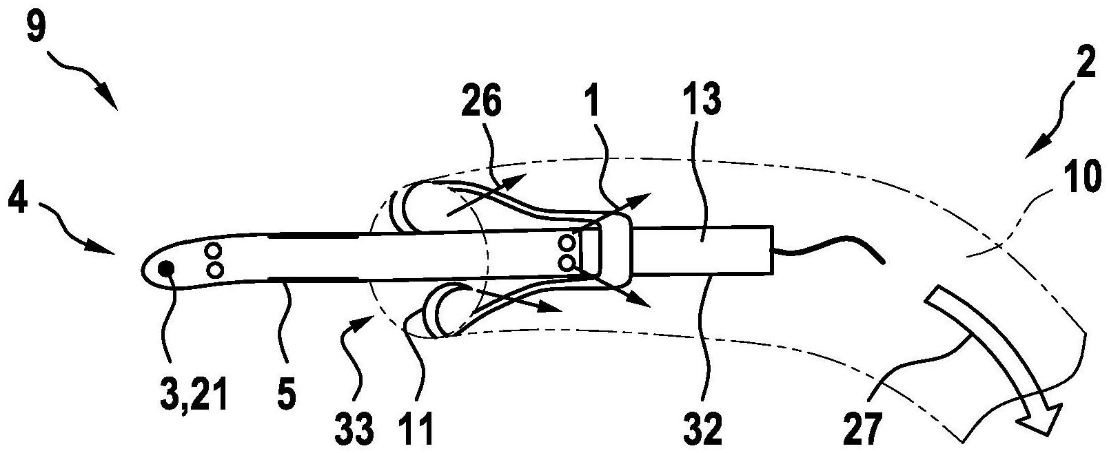
Das Unterstützungssystem
Zudem ist in
Im Bereich der Kanüle
Bei dem Temperatursensor
Wird ein separater Referenz-Temperatursensor genutzt, wie dies nach der Darstellung gemäß
Das Wirkprinzip beruht hier darauf, bei hinreichend bekannter thermischer Kapazität (Formelzeichen C; vgl. Bezugszeichen ![]()
![]()
Bei hinreichend bekannter Wärmekapazität C (wird im Algorithmus vorgehalten), gemessenem Energiezufluss dQ und aus zwei gemessenen (Fluid-)Temperaturen ermitteltem Temperaturhub dT kann somit das im Beobachtungszeitrum umgesetzte Flüssigkeitsvolumen V bzw. der Fluid-Volumenstrom
Das Heizelement
Zur Betriebsweise der Ausführung nach
Der in
Bei der Ausführung als Konstantstrom-Anemometrie wird das Heizelement
Bei der Ausführung als Konstanttemperatur-Anemometrie wird die Heizelementtemperatur
Das Heizelement
Die beobachtbaren Effekte sind sowohl eine Laufzeit, wobei ein hoher Fluid-Volumenstrom
Die hier vorgeschlagene Lösung ermöglicht insbesondere einen oder mehrere der nachstehenden Vorteile:
- • Durch Integration des Sensors in die Einlaufkanüle des VAD wird ein Gewebekontakt zum Heizelement verhindert, wodurch eine Gewebeschädigung verhindert wird.
- • Die Integration in die Einlaufkanüle hat den Vorteil, dass die (durchströmte) Geometrie und damit das untersuchte Blutvolumen bekannt ist, was die Kalibrierung des Sensors je nach Realisierungsvariante vereinfacht bzw. ersetzt. Marktübliche Katheter erfordern die Gabe eines Eiswasser-Bolus, um auf das Blutgefäßvolumen zu kalibrieren.
- • Eine kontinuierliche Qp-Messung ermöglicht die schnelle Diagnose von suction, d.h. einem Ansaugen des Einlaufschlauches an die Ventrikelwand, wodurch die Pumpenfunktion beeinträchtigt wird.
- • Integration of the sensor into the inlet cannula of the VAD prevents tissue contact with the heating element, preventing tissue damage.
- • The integration into the inlet cannula has the advantage that the (flowed) geometry and thus the examined blood volume is known, which simplifies or replaces the calibration of the sensor depending on the implementation variant. Standard catheters require the administration of an ice water bolus to calibrate for blood vessel volume.
- • Continuous Q p measurement allows rapid diagnosis of suction, ie aspiration of the inlet tubing to the ventricular wall, thereby compromising pump function.
Claims (10)
Priority Applications (6)
| Application Number | Priority Date | Filing Date | Title |
|---|---|---|---|
| DE102018208870.5A DE102018208870A1 (en) | 2018-06-06 | 2018-06-06 | A method of determining a fluid volume flow through an implanted vascular support system |
| PCT/EP2019/064800 WO2019234161A1 (en) | 2018-06-06 | 2019-06-06 | Method for determining a fluid volume flow through an implanted vascular support system and vascular support system |
| EP19729726.0A EP3801666A1 (en) | 2018-06-06 | 2019-06-06 | Method for determining a fluid volume flow through an implanted vascular support system and vascular support system |
| US15/734,004 US12491357B2 (en) | 2018-06-06 | 2019-06-06 | Systems and methods for determining a blood volume flow through a cardiac support system and vascular support system |
| JP2020567788A JP7515176B2 (en) | 2018-06-06 | 2019-06-06 | Method for determining volumetric fluid flow through an implanted vascular assist system and vascular assist system - Patents.com |
| CN201980048719.3A CN112533660B (en) | 2018-06-06 | 2019-06-06 | Method for determining a fluid volume flow through an implantable vascular support system and vascular support system |
Applications Claiming Priority (1)
| Application Number | Priority Date | Filing Date | Title |
|---|---|---|---|
| DE102018208870.5A DE102018208870A1 (en) | 2018-06-06 | 2018-06-06 | A method of determining a fluid volume flow through an implanted vascular support system |
Publications (1)
| Publication Number | Publication Date |
|---|---|
| DE102018208870A1 true DE102018208870A1 (en) | 2019-12-12 |
Family
ID=66821249
Family Applications (1)
| Application Number | Title | Priority Date | Filing Date |
|---|---|---|---|
| DE102018208870.5A Pending DE102018208870A1 (en) | 2018-06-06 | 2018-06-06 | A method of determining a fluid volume flow through an implanted vascular support system |
Country Status (6)
| Country | Link |
|---|---|
| US (1) | US12491357B2 (en) |
| EP (1) | EP3801666A1 (en) |
| JP (1) | JP7515176B2 (en) |
| CN (1) | CN112533660B (en) |
| DE (1) | DE102018208870A1 (en) |
| WO (1) | WO2019234161A1 (en) |
Families Citing this family (16)
| Publication number | Priority date | Publication date | Assignee | Title |
|---|---|---|---|---|
| DE102018208538A1 (en) | 2018-05-30 | 2019-12-05 | Kardion Gmbh | Intravascular blood pump and process for the production of electrical conductors |
| DE102018208929A1 (en) | 2018-06-06 | 2019-12-12 | Kardion Gmbh | A method of determining a flow rate of fluid flowing through an implanted vascular support system |
| DE102018208945A1 (en) | 2018-06-06 | 2019-12-12 | Kardion Gmbh | An analysis device and method for analyzing a viscosity of a fluid |
| DE102018208892A1 (en) | 2018-06-06 | 2019-12-12 | Kardion Gmbh | A sensor head device for a minimally invasive cardiac assist system and method of manufacturing a sensor head device for a cardiac assist system |
| DE102018208879A1 (en) | 2018-06-06 | 2020-01-30 | Kardion Gmbh | Method for determining a total fluid volume flow in the area of an implanted, vascular support system |
| DE102018208899A1 (en) | 2018-06-06 | 2019-12-12 | Kardion Gmbh | A method for determining the speed of sound in a fluid in the region of an implanted vascular support system |
| DE102018208936A1 (en) | 2018-06-06 | 2019-12-12 | Kardion Gmbh | Determining device and method for determining a viscosity of a fluid |
| DE102018208933A1 (en) | 2018-06-06 | 2019-12-12 | Kardion Gmbh | A method of determining a flow rate of fluid flowing through an implanted vascular support system |
| DE102018208870A1 (en) | 2018-06-06 | 2019-12-12 | Kardion Gmbh | A method of determining a fluid volume flow through an implanted vascular support system |
| DE102018208862A1 (en) | 2018-06-06 | 2019-12-12 | Kardion Gmbh | Implantable vascular support system |
| DE102018208913A1 (en) | 2018-06-06 | 2019-12-12 | Kardion Gmbh | A method of operating an implanted ventricular assist device |
| DE102018210076A1 (en) | 2018-06-21 | 2019-12-24 | Kardion Gmbh | Method and device for detecting a state of wear of a cardiac support system, method and device for operating a cardiac support system and cardiac support system |
| DE102018213350A1 (en) | 2018-08-08 | 2020-02-13 | Kardion Gmbh | Device and method for monitoring a patient's health |
| US12502524B2 (en) | 2021-12-03 | 2025-12-23 | Kardion Gmbh | Cardiac pump with optical fiber for laser doppler |
| CN116672595B (en) * | 2022-02-23 | 2025-09-16 | 上海微创心力医疗科技有限公司 | Method and device for judging placement position of catheter pump, control equipment and storage medium |
| WO2025085887A1 (en) * | 2023-10-20 | 2025-04-24 | Carilion Clinic | Device for measuring rate of body fluid flow through a tube |
Family Cites Families (622)
| Publication number | Priority date | Publication date | Assignee | Title |
|---|---|---|---|---|
| US3088323A (en) | 1960-02-10 | 1963-05-07 | Gulton Ind Inc | Piezoresistive transducer |
| US4023562A (en) | 1975-09-02 | 1977-05-17 | Case Western Reserve University | Miniature pressure transducer for medical use and assembly method |
| NO150015C (en) | 1981-11-13 | 1984-08-08 | Vingmed As | METHOD OF BLOOD FLOW SPEED MEASUREMENT WITH ULTRO SOUND, COMBINED WITH ECO-AMPLITUDE IMAGE, FOR THE INVESTIGATION OF LIVING BIOLOGICAL STRUCTURES |
| JPS5980229A (en) | 1982-10-29 | 1984-05-09 | 株式会社島津製作所 | Pulse doppler ultrasonic blood flow meter |
| JPS6015771A (en) | 1983-07-08 | 1985-01-26 | Hitachi Ltd | Memory controller |
| JPS61125329A (en) * | 1984-11-21 | 1986-06-13 | テルモ株式会社 | Heart pulse output measuring apparatus |
| JPS62113555A (en) | 1985-11-13 | 1987-05-25 | Canon Inc | Ink jet recorder |
| JPS62204733A (en) | 1986-03-04 | 1987-09-09 | アロカ株式会社 | Ultrasonic doppler diagnostic apparatus |
| JPS62282284A (en) | 1986-05-30 | 1987-12-08 | Tokyo Keiki Co Ltd | Method and apparatus for measuring distance by ultrasonic wave |
| US4902272A (en) | 1987-06-17 | 1990-02-20 | Abiomed Cardiovascular, Inc. | Intra-arterial cardiac support system |
| US4781525A (en) | 1987-07-17 | 1988-11-01 | Minnesota Mining And Manufacturing Company | Flow measurement system |
| JPS6468236A (en) | 1987-09-07 | 1989-03-14 | Aisin Seiki | Cannula equipped with detection electrode |
| US4889131A (en) | 1987-12-03 | 1989-12-26 | American Health Products, Inc. | Portable belt monitor of physiological functions and sensors therefor |
| WO1989006513A1 (en) | 1988-01-25 | 1989-07-27 | Baylor College Of Medicine | Implantable and extractable biological sensor probe |
| US4888011A (en) | 1988-07-07 | 1989-12-19 | Abiomed, Inc. | Artificial heart |
| US4965713A (en) | 1988-08-15 | 1990-10-23 | Viking Pump Inc. | Terminal element |
| US4989609A (en) | 1989-01-26 | 1991-02-05 | Minnesota Mining And Manufacturing Company | Doppler blood flow system and method using special zero flow rate analysis |
| US5045051A (en) | 1989-03-14 | 1991-09-03 | Abiomed, Inc. | Leak detector |
| CA2004295C (en) * | 1989-11-30 | 1998-02-10 | William F. Hayes | Primary fluid actuated, secondary fluid propelling system |
| WO1992015239A1 (en) | 1991-02-04 | 1992-09-17 | Kensey Nash Corporation | Apparatus and method for determining viscosity of the blood of a living being |
| JP2952438B2 (en) * | 1991-09-20 | 1999-09-27 | トキコ株式会社 | Thermal flow meter |
| US5676651A (en) | 1992-08-06 | 1997-10-14 | Electric Boat Corporation | Surgically implantable pump arrangement and method for pumping body fluids |
| US5376114A (en) | 1992-10-30 | 1994-12-27 | Jarvik; Robert | Cannula pumps for temporary cardiac support and methods of their application and use |
| JP3312759B2 (en) | 1993-01-22 | 2002-08-12 | テルモ株式会社 | Medical pump drive |
| US5456715A (en) | 1993-05-21 | 1995-10-10 | Liotta; Domingo S. | Implantable mechanical system for assisting blood circulation |
| US5289821A (en) | 1993-06-30 | 1994-03-01 | Swartz William M | Method of ultrasonic Doppler monitoring of blood flow in a blood vessel |
| JPH0747025A (en) | 1993-08-06 | 1995-02-21 | Itoki Co Ltd | Flexible partition |
| US5527159A (en) | 1993-11-10 | 1996-06-18 | The United States Of America As Represented By The Administrator Of The National Aeronautics And Space Administration | Rotary blood pump |
| GB9404321D0 (en) | 1994-03-04 | 1994-04-20 | Thoratec Lab Corp | Driver and method for driving pneumatic ventricular assist devices |
| US5581038A (en) | 1994-04-04 | 1996-12-03 | Sentir, Inc. | Pressure measurement apparatus having a reverse mounted transducer and overpressure guard |
| NO942222D0 (en) | 1994-06-14 | 1994-06-14 | Vingmed Sound As | Method for determining blood flow velocity / time spectrum |
| JPH0857042A (en) | 1994-08-24 | 1996-03-05 | Terumo Corp | Medical pump |
| US5685989A (en) | 1994-09-16 | 1997-11-11 | Transonic Systems, Inc. | Method and apparatus to measure blood flow and recirculation in hemodialysis shunts |
| US5453576A (en) | 1994-10-24 | 1995-09-26 | Transonic Systems Inc. | Cardiovascular measurements by sound velocity dilution |
| US5613935A (en) | 1994-12-16 | 1997-03-25 | Jarvik; Robert | High reliability cardiac assist system |
| JPH08327527A (en) | 1995-05-31 | 1996-12-13 | Toyobo Co Ltd | Capillary type viscometer |
| WO1999015212A1 (en) | 1997-09-24 | 1999-04-01 | The Cleveland Clinic Foundation | Flow controlled blood pump system |
| US5752976A (en) | 1995-06-23 | 1998-05-19 | Medtronic, Inc. | World wide patient location and data telemetry system for implantable medical devices |
| US5720771A (en) | 1995-08-02 | 1998-02-24 | Pacesetter, Inc. | Method and apparatus for monitoring physiological data from an implantable medical device |
| GB9604665D0 (en) | 1996-03-05 | 1996-05-01 | Montec Int Ltd | Flow measurement |
| US5980465A (en) | 1996-03-18 | 1999-11-09 | Medtronic, Inc. | Method for detecting changes in a patient s blood volume |
| US5911685A (en) | 1996-04-03 | 1999-06-15 | Guidant Corporation | Method and apparatus for cardiac blood flow assistance |
| JPH1052489A (en) | 1996-08-12 | 1998-02-24 | Buaayu:Kk | Cannula and supplemental circulation device |
| US5888242A (en) | 1996-11-01 | 1999-03-30 | Nimbus, Inc. | Speed control system for implanted blood pumps |
| ES2208963T3 (en) | 1997-01-03 | 2004-06-16 | Biosense, Inc. | PRESSURE SENSITIVE VASCULAR ENDOPROTESIS. |
| US5957861A (en) | 1997-01-31 | 1999-09-28 | Medtronic, Inc. | Impedance monitor for discerning edema through evaluation of respiratory rate |
| US5964694A (en) | 1997-04-02 | 1999-10-12 | Guidant Corporation | Method and apparatus for cardiac blood flow assistance |
| CN1222862A (en) | 1997-04-02 | 1999-07-14 | 激励心脏技术有限公司 | intracardiac pump device |
| US5865759A (en) | 1997-04-11 | 1999-02-02 | Texon Technologies Ltd. | Method and apparatus for non-invasive assessment of cardiac function by monitoring acceleration of the heart |
| US5827203A (en) | 1997-04-21 | 1998-10-27 | Nita; Henry | Ultrasound system and method for myocardial revascularization |
| US6731976B2 (en) | 1997-09-03 | 2004-05-04 | Medtronic, Inc. | Device and method to measure and communicate body parameters |
| DE69836495T3 (en) | 1997-10-02 | 2015-08-06 | Micromed Technology, Inc. | Control module for implantable pumping system |
| US6610004B2 (en) | 1997-10-09 | 2003-08-26 | Orqis Medical Corporation | Implantable heart assist system and method of applying same |
| US6398734B1 (en) | 1997-10-14 | 2002-06-04 | Vascusense, Inc. | Ultrasonic sensors for monitoring the condition of flow through a cardiac valve |
| US6007478A (en) | 1997-11-13 | 1999-12-28 | Impella Cardiotechnik Aktiengesellschaft | Cannula having constant wall thickness with increasing distal flexibility and method of making |
| US6314322B1 (en) | 1998-03-02 | 2001-11-06 | Abiomed, Inc. | System and method for treating dilated cardiomyopathy using end diastolic volume (EDV) sensing |
| US5904708A (en) | 1998-03-19 | 1999-05-18 | Medtronic, Inc. | System and method for deriving relative physiologic signals |
| CN1192351A (en) | 1998-03-26 | 1998-09-09 | 王明时 | Instrument for quick measuring blood viscosity |
| US6176822B1 (en) | 1998-03-31 | 2001-01-23 | Impella Cardiotechnik Gmbh | Intracardiac blood pump |
| US6023641A (en) | 1998-04-29 | 2000-02-08 | Medtronic, Inc. | Power consumption reduction in medical devices employing multiple digital signal processors |
| US6024704A (en) | 1998-04-30 | 2000-02-15 | Medtronic, Inc | Implantable medical device for sensing absolute blood pressure and barometric pressure |
| DE19821307C1 (en) | 1998-05-13 | 1999-10-21 | Impella Cardiotech Gmbh | Intra-cardiac blood pump |
| WO1999060941A1 (en) | 1998-05-26 | 1999-12-02 | Circulation, Inc. | Apparatus for providing coronary retroperfusion and methods of use |
| US6167765B1 (en) | 1998-09-25 | 2001-01-02 | The Regents Of The University Of Michigan | System and method for determining the flow rate of blood in a vessel using doppler frequency signals |
| US6575927B1 (en) | 1998-09-25 | 2003-06-10 | The Regents Of The University Of Michigan | System and method for determining blood flow rate in a vessel |
| DE29821563U1 (en) | 1998-12-02 | 2000-07-13 | Impella Cardiotechnik AG, 52074 Aachen | Pressure sensor |
| US6245007B1 (en) | 1999-01-28 | 2001-06-12 | Terumo Cardiovascular Systems Corporation | Blood pump |
| US6210318B1 (en) | 1999-03-09 | 2001-04-03 | Abiomed, Inc. | Stented balloon pump system and method for using same |
| US6438409B1 (en) | 1999-03-25 | 2002-08-20 | Medtronic, Inc. | Methods of characterizing ventricular operations and applications thereof |
| IT1315206B1 (en) | 1999-04-27 | 2003-02-03 | Salvatore Romano | METHOD AND APPARATUS FOR MEASURING HEART RATE. |
| US6190324B1 (en) | 1999-04-28 | 2001-02-20 | Medtronic, Inc. | Implantable medical device for tracking patient cardiac status |
| AUPQ090499A0 (en) | 1999-06-10 | 1999-07-01 | Peters, William S | Heart assist device and system |
| US6890329B2 (en) | 1999-06-15 | 2005-05-10 | Cryocath Technologies Inc. | Defined deflection structure |
| EP1063753B1 (en) | 1999-06-22 | 2009-07-22 | Levitronix LLC | Electric rotary drive comprising a magnetically suspended rotor |
| US6231498B1 (en) | 1999-06-23 | 2001-05-15 | Pulsion Medical Systems Ag | Combined catheter system for IABP and determination of thermodilution cardiac output |
| US7138776B1 (en) | 1999-07-08 | 2006-11-21 | Heartware, Inc. | Method and apparatus for controlling brushless DC motors in implantable medical devices |
| US6512949B1 (en) | 1999-07-12 | 2003-01-28 | Medtronic, Inc. | Implantable medical device for measuring time varying physiologic conditions especially edema and for responding thereto |
| WO2001017581A2 (en) | 1999-09-03 | 2001-03-15 | A-Med Systems, Inc. | Guidable intravascular blood pump and related methods |
| US7022100B1 (en) | 1999-09-03 | 2006-04-04 | A-Med Systems, Inc. | Guidable intravascular blood pump and related methods |
| US6579257B1 (en) | 1999-09-21 | 2003-06-17 | Medtronic, Inc. | Automated occlusion clamp for centrifugal blood pumps |
| US20010039828A1 (en) | 1999-11-12 | 2001-11-15 | Visco Technologies, Inc. | Mass detection capillary viscometer |
| US6593840B2 (en) | 2000-01-31 | 2003-07-15 | Pulse Engineering, Inc. | Electronic packaging device with insertable leads and method of manufacturing |
| EP1123687A3 (en) | 2000-02-10 | 2004-02-04 | Aloka Co., Ltd. | Ultrasonic diagnostic apparatus |
| US6406422B1 (en) | 2000-03-02 | 2002-06-18 | Levram Medical Devices, Ltd. | Ventricular-assist method and apparatus |
| US6561975B1 (en) | 2000-04-19 | 2003-05-13 | Medtronic, Inc. | Method and apparatus for communicating with medical device systems |
| US6432136B1 (en) | 2000-04-25 | 2002-08-13 | The Penn State Research Foundation | Apparatus and method for removing a pocket of air from a blood pump |
| US6530876B1 (en) | 2000-04-25 | 2003-03-11 | Paul A. Spence | Supplemental heart pump methods and systems for supplementing blood through the heart |
| US6540658B1 (en) | 2000-05-30 | 2003-04-01 | Abiomed, Inc. | Left-right flow control algorithm in a two chamber cardiac prosthesis |
| DE10040403A1 (en) | 2000-08-18 | 2002-02-28 | Impella Cardiotech Ag | Intracardiac blood pump |
| IL138073A0 (en) | 2000-08-24 | 2001-10-31 | Glucon Inc | Photoacoustic assay and imaging system |
| US6808508B1 (en) | 2000-09-13 | 2004-10-26 | Cardiacassist, Inc. | Method and system for closed chest blood flow support |
| GB0023412D0 (en) | 2000-09-23 | 2000-11-08 | Khaghani Asghar | Aortic counterpulsator |
| US6602182B1 (en) | 2000-11-28 | 2003-08-05 | Abiomed, Inc. | Cardiac assistance systems having multiple fluid plenums |
| US6540659B1 (en) | 2000-11-28 | 2003-04-01 | Abiomed, Inc. | Cardiac assistance systems having bi-directional pumping elements |
| DE10059714C1 (en) | 2000-12-01 | 2002-05-08 | Impella Cardiotech Ag | Intravasal pump has pump stage fitted with flexible expandible sleeve contricted during insertion through blood vessel |
| DE10060275A1 (en) | 2000-12-05 | 2002-06-13 | Impella Cardiotech Ag | Method for calibrating a pressure sensor or a flow sensor on a rotary pump |
| US6912423B2 (en) | 2000-12-15 | 2005-06-28 | Cardiac Pacemakers, Inc. | Terminal connector assembly for a medical device and method therefor |
| US20020147495A1 (en) | 2001-04-09 | 2002-10-10 | Christopher Petroff | Reduced-size replacement heart |
| DE10164898B4 (en) | 2001-04-30 | 2010-09-23 | Berlin Heart Gmbh | Method for controlling a support pump for pulsatile pressure fluid delivery systems |
| US6511413B2 (en) | 2001-05-16 | 2003-01-28 | Levram Medical Devices, Ltd. | Single cannula ventricular-assist method and apparatus |
| US6879126B2 (en) | 2001-06-29 | 2005-04-12 | Medquest Products, Inc | Method and system for positioning a movable body in a magnetic bearing system |
| JP3882069B2 (en) | 2001-07-06 | 2007-02-14 | 独立行政法人産業技術総合研究所 | Abnormality determination method and abnormality determination device for artificial heart pump |
| US7191000B2 (en) | 2001-07-31 | 2007-03-13 | Cardiac Pacemakers, Inc. | Cardiac rhythm management system for edema |
| JP4440499B2 (en) | 2001-08-29 | 2010-03-24 | 泉工医科工業株式会社 | Centrifugal pump drive |
| DE10144269A1 (en) | 2001-09-08 | 2003-03-27 | Bosch Gmbh Robert | Sensor element for measuring a physical variable between two bodies which move relative to each other and are subjected to high tribological strain, whereby the element has very high wear resistance to increase its service life |
| US6666826B2 (en) | 2002-01-04 | 2003-12-23 | Cardiac Pacemakers, Inc. | Method and apparatus for measuring left ventricular pressure |
| US7396327B2 (en) | 2002-01-07 | 2008-07-08 | Micromed Technology, Inc. | Blood pump system and method of operation |
| US8323173B2 (en) | 2002-01-07 | 2012-12-04 | Micromed Technology, Inc. | Method and system for physiologic control of an implantable blood pump |
| AU2003202250A1 (en) | 2002-01-08 | 2003-07-24 | Micromed Technology, Inc. | Method and system for detecting ventricular collapse |
| DK2298370T3 (en) | 2002-02-21 | 2014-01-27 | Design Mentor Inc | fluid pump |
| US7238151B2 (en) | 2002-02-26 | 2007-07-03 | Frazier O Howard | Permanent heart assist system |
| US6669624B2 (en) | 2002-03-26 | 2003-12-30 | O. Howard Frazier | Temporary heart-assist system |
| US10155082B2 (en) | 2002-04-10 | 2018-12-18 | Baxter International Inc. | Enhanced signal detection for access disconnection systems |
| US6991595B2 (en) | 2002-04-19 | 2006-01-31 | Thoratec Corporation | Adaptive speed control for blood pump |
| US7024244B2 (en) | 2002-04-22 | 2006-04-04 | Medtronic, Inc. | Estimation of stroke volume cardiac output using an intracardiac pressure sensor |
| US6969369B2 (en) | 2002-04-22 | 2005-11-29 | Medtronic, Inc. | Implantable drug delivery system responsive to intra-cardiac pressure |
| DE10226305C1 (en) | 2002-06-13 | 2003-10-30 | Infratec Gmbh Infrarotsensorik | Tunable narrowband filter for IR spectral measurements based on electrostatically-driven micromechanical Fabry-Perot interferometer |
| DE10227918A1 (en) | 2002-06-21 | 2004-01-15 | Bühler AG | Method for determining rheological parameters of a fluid |
| AU2003238656A1 (en) | 2002-06-25 | 2004-01-06 | Glucon Inc. | Method and apparatus for performing myocardial revascularization |
| US6949066B2 (en) | 2002-08-21 | 2005-09-27 | World Heart Corporation | Rotary blood pump diagnostics and cardiac output controller |
| AU2002951685A0 (en) | 2002-09-30 | 2002-10-17 | Ventrassist Pty Ltd | Physiological demand responsive control system |
| US6943434B2 (en) | 2002-10-03 | 2005-09-13 | Fairchild Semiconductor Corporation | Method for maintaining solder thickness in flipchip attach packaging processes |
| US7207939B2 (en) | 2002-10-03 | 2007-04-24 | Coulter International Corp. | Apparatus and method for analyzing a liquid in a capillary tube of a hematology instrument |
| US7289029B2 (en) | 2002-12-31 | 2007-10-30 | Medtronic Physio-Control Corp. | Communication between emergency medical device and safety agency |
| US7204798B2 (en) | 2003-01-24 | 2007-04-17 | Proteus Biomedical, Inc. | Methods and systems for measuring cardiac parameters |
| EP1592344A4 (en) | 2003-01-31 | 2006-08-16 | Univ Leland Stanford Junior | APEX MOTION DETECTION FOR MONITORING CARDIAC DYSFUNCTIONS |
| US6887207B2 (en) | 2003-02-26 | 2005-05-03 | Medtronic, Inc. | Methods and apparatus for estimation of ventricular afterload based on ventricular pressure measurements |
| US20040199052A1 (en) | 2003-04-01 | 2004-10-07 | Scimed Life Systems, Inc. | Endoscopic imaging system |
| CN1202871C (en) | 2003-04-18 | 2005-05-25 | 清华大学 | Optimal non-constant speed control method for miniature axial flow type blood pumps |
| US7118525B2 (en) | 2003-04-23 | 2006-10-10 | Coleman Edward J | Implantable cardiac assist device |
| US20080262289A1 (en) | 2003-05-28 | 2008-10-23 | Goldowsky Michael P | Blood Pump Having A Passive Non-Contacting Bearing Suspension |
| US20040241019A1 (en) | 2003-05-28 | 2004-12-02 | Michael Goldowsky | Passive non-contacting smart bearing suspension for turbo blood-pumps |
| US7078796B2 (en) | 2003-07-01 | 2006-07-18 | Freescale Semiconductor, Inc. | Corrosion-resistant copper bond pad and integrated device |
| US7128538B2 (en) | 2003-07-07 | 2006-10-31 | Terumo Corporation | Centrifugal fluid pump apparatus |
| AU2003903726A0 (en) | 2003-07-18 | 2003-07-31 | Ventracor Limited | A device for detecting heart pumping state |
| US7951129B2 (en) | 2003-08-07 | 2011-05-31 | Medtronic, Inc. | Diastolic coronary perfusion detection for timed delivery of therapeutic and/or diagnostic agents |
| DE10336902C5 (en) | 2003-08-08 | 2019-04-25 | Abiomed Europe Gmbh | Intracardiac pumping device |
| US7245117B1 (en) | 2004-11-01 | 2007-07-17 | Cardiomems, Inc. | Communicating with implanted wireless sensor |
| US20140296677A1 (en) | 2003-09-18 | 2014-10-02 | New Paradigm Concepts, LLC | Method of measuring total vascular hemoglobin mass |
| US7559894B2 (en) | 2003-09-18 | 2009-07-14 | New Paradigm Concepts, LLC | Multiparameter whole blood monitor and method |
| US20050137614A1 (en) | 2003-10-08 | 2005-06-23 | Porter Christopher H. | System and method for connecting implanted conduits |
| US8428717B2 (en) | 2003-10-14 | 2013-04-23 | Medtronic, Inc. | Method and apparatus for monitoring tissue fluid content for use in an implantable cardiac device |
| EP3028739A1 (en) | 2003-10-31 | 2016-06-08 | Sunshine Heart Company Pty Ltd | Synchronisation control system |
| WO2005051838A2 (en) | 2003-11-19 | 2005-06-09 | Transoma Medical, Inc. | Feedback control of ventricular assist devices |
| CA2589197C (en) | 2003-11-26 | 2012-03-20 | Separation Technology, Inc. | Method and apparatus for ultrasonic determination of hematocrit and hemoglobin concentrations |
| TWI231749B (en) | 2003-12-24 | 2005-05-01 | Mau-Chin Shen | Restoring/positioning device for slide rail of drawer |
| JP2005192687A (en) | 2003-12-29 | 2005-07-21 | Sunao Kitamura | Indirect measuring method for pressure, flow rate and natural cardiac output in partial assist using rotating artificial heart pump |
| JP2005241546A (en) | 2004-02-27 | 2005-09-08 | Fuji Electric Systems Co Ltd | Doppler type ultrasonic flowmeter, its processing unit, program |
| US11819192B2 (en) | 2004-03-23 | 2023-11-21 | Boston Scientific Scimed, Inc. | In-vivo visualization system |
| US7160243B2 (en) | 2004-03-25 | 2007-01-09 | Terumo Corporation | Method and system for controlling blood pump flow |
| US7591777B2 (en) | 2004-05-25 | 2009-09-22 | Heartware Inc. | Sensorless flow estimation for implanted ventricle assist device |
| US7513864B2 (en) | 2004-07-09 | 2009-04-07 | Kantrowitz Allen B | Synchronization system between aortic valve and cardiac assist device |
| WO2006006163A2 (en) | 2004-07-12 | 2006-01-19 | Coreolis Inc. | Apparatus and method for multiple organ assist |
| US20070299325A1 (en) | 2004-08-20 | 2007-12-27 | Brian Farrell | Physiological status monitoring system |
| CN101048186A (en) | 2004-09-07 | 2007-10-03 | 心血管微创医疗公司 | Method and system for physiologic control of a blood pump |
| EP1830917B1 (en) | 2004-11-02 | 2013-06-05 | St. Jude Medical AB | Device for evaluating positions of an implantable medical device |
| ATE520429T1 (en) | 2004-11-16 | 2011-09-15 | Micromed Technology Inc | DISTANCE DATA MONITOR FOR A HEART PUMP SYSTEM |
| US7339275B2 (en) | 2004-11-22 | 2008-03-04 | Freescale Semiconductor, Inc. | Multi-chips semiconductor device assemblies and methods for fabricating the same |
| DE102005003632A1 (en) | 2005-01-20 | 2006-08-17 | Fraunhofer-Gesellschaft zur Förderung der angewandten Forschung e.V. | Catheter for the transvascular implantation of heart valve prostheses |
| WO2006080011A2 (en) | 2005-01-25 | 2006-08-03 | Ramot At Tel Aviv University Ltd. | Using pulsed-wave ultrasonography for determining an aliasing-free radial velocity spectrum of matter moving in a region |
| US8594790B2 (en) | 2005-01-27 | 2013-11-26 | Medtronic, Inc. | System and method for monitoring a ventricular pressure index to predict worsening heart failure |
| US20060217771A1 (en) | 2005-02-07 | 2006-09-28 | Medtronic, Inc. | Potassium monitoring |
| US7563248B2 (en) | 2005-03-17 | 2009-07-21 | Smisson-Cartledge Biomedical Llc | Infusion fluid heat exchanger and cartridge |
| DE102005017546A1 (en) | 2005-04-16 | 2006-10-19 | Impella Cardiosystems Gmbh | Method for controlling a blood pump |
| ES2425388T3 (en) | 2005-05-06 | 2013-10-15 | Vasonova, Inc. | Apparatus for guiding and positioning an endovascular device |
| US7526338B1 (en) | 2005-05-23 | 2009-04-28 | Pacesetter, Inc. | Implantable cardiac device for monitoring diastolic heart failure and method of operation and use thereof |
| CA2611313A1 (en) | 2005-06-06 | 2006-12-14 | The Cleveland Clinic Foundation | Blood pump |
| EP1893075A4 (en) | 2005-06-08 | 2013-06-19 | Micromed Technology Inc | Artificial heart system |
| WO2006138728A2 (en) | 2005-06-17 | 2006-12-28 | The Research Foundation Of State University Of New York | Method of determining cardiac indicators |
| WO2007002185A2 (en) | 2005-06-21 | 2007-01-04 | Cardiomems, Inc. | Method of manufacturing implantable wireless sensor for in vivo pressure measurement |
| DE102005039446B4 (en) | 2005-08-18 | 2009-06-25 | Ilias-Medical Gmbh | Device for accumulating and depleting substances in a liquid |
| DE102005046008B4 (en) | 2005-09-26 | 2007-05-24 | Infineon Technologies Ag | Semiconductor sensor component with sensor chip and method for producing the same |
| US8657875B2 (en) | 2005-09-26 | 2014-02-25 | Abiomed, Inc. | Method and apparatus for pumping blood |
| US20070073352A1 (en) | 2005-09-28 | 2007-03-29 | Euler David E | Method and apparatus for regulating a cardiac stimulation therapy |
| US20070088214A1 (en) | 2005-10-14 | 2007-04-19 | Cardiac Pacemakers Inc. | Implantable physiologic monitoring system |
| US20070142923A1 (en) | 2005-11-04 | 2007-06-21 | Ayre Peter J | Control systems for rotary blood pumps |
| DE102005053765B4 (en) | 2005-11-10 | 2016-04-14 | Epcos Ag | MEMS package and method of manufacture |
| EP1813302A1 (en) * | 2006-01-25 | 2007-08-01 | Debiotech S.A. | Fluid volume measurement device for medical use |
| DE102006001180B4 (en) | 2006-01-06 | 2010-12-23 | Technische Universität Chemnitz | Rheometer and evaluation method for the determination of flow curve and viscosity function of optically transparent Newtonian and non-Newtonian fluids |
| US20110022057A1 (en) | 2006-02-03 | 2011-01-27 | Pacesetter, Inc. | Apparatus and methods for transferring an implanted elongate body to a remote site |
| EP1990066B1 (en) | 2006-02-23 | 2017-03-08 | Thoratec Delaware LLC | A pump-outflow-cannula and a blood managing system |
| AU2007201127B2 (en) | 2006-03-23 | 2012-02-09 | Thoratec Corporation | System For Preventing Diastolic Heart Failure |
| WO2007112033A2 (en) | 2006-03-23 | 2007-10-04 | The Penn State Research Foundation | Heart assist device with expandable impeller pump |
| AT503628B1 (en) | 2006-04-25 | 2008-06-15 | Vc Trust Holding Gmbh | METHOD FOR MONITORING THE MAXIMUM DISTANCE OF TWO OBJECTS |
| US20070255352A1 (en) | 2006-04-27 | 2007-11-01 | Roline Glen M | Implantable sensors having current-based switches for improved fault tolerance |
| US7549964B2 (en) | 2006-05-04 | 2009-06-23 | Viasys Healthcare, Inc. | Multiple frequency doppler ultrasound probe |
| US7850594B2 (en) | 2006-05-09 | 2010-12-14 | Thoratec Corporation | Pulsatile control system for a rotary blood pump |
| US7468039B2 (en) | 2006-06-02 | 2008-12-23 | Cook Vascular Incorporated | Adjustable tension cuff assembly |
| US7909770B2 (en) | 2006-07-05 | 2011-03-22 | Cardiomems, Inc. | Method for using a wireless pressure sensor to monitor pressure inside the human heart |
| DE102006032583A1 (en) | 2006-07-13 | 2008-01-17 | Biotronik Crm Patent Ag | introducer |
| DE102006035547A1 (en) | 2006-07-27 | 2008-02-21 | Deutsches Zentrum für Luft- und Raumfahrt e.V. | Transfer arrangement |
| DE102006035548B4 (en) | 2006-07-27 | 2009-02-12 | Deutsches Zentrum für Luft- und Raumfahrt e.V. | artificial heart |
| US20080097595A1 (en) | 2006-08-22 | 2008-04-24 | Shlomo Gabbay | Intraventricular cardiac prosthesis |
| CA2663586C (en) | 2006-09-14 | 2014-10-28 | Circulite, Inc | Intravascular blood pump and catheter |
| EP1903000B1 (en) | 2006-09-25 | 2019-09-18 | Sorin CRM SAS | Implantable biocompatible component including an integrated active element such as a sensor for measuring a physiological parameter, electromechanical microsystem or electronic circuit |
| US7963905B2 (en) | 2006-10-11 | 2011-06-21 | Thoratec Corporation | Control system for a blood pump |
| US20080091239A1 (en) | 2006-10-16 | 2008-04-17 | St. Jude Medical Ab | Cardiac assist device and method using epicardially placed microphone |
| US20080133006A1 (en) | 2006-10-27 | 2008-06-05 | Ventrassist Pty Ltd | Blood Pump With An Ultrasonic Transducer |
| JP5283888B2 (en) | 2006-11-02 | 2013-09-04 | 株式会社東芝 | Ultrasonic diagnostic equipment |
| WO2008057478A2 (en) | 2006-11-03 | 2008-05-15 | The Regents Of The University Of Michigan | Method and system for determining volume flow in a blood conduit |
| US8202224B2 (en) | 2006-11-13 | 2012-06-19 | Pacesetter, Inc. | System and method for calibrating cardiac pressure measurements derived from signals detected by an implantable medical device |
| US20080142946A1 (en) | 2006-12-13 | 2008-06-19 | Advanced Chip Engineering Technology Inc. | Wafer level package with good cte performance |
| AT504990B1 (en) | 2007-02-27 | 2008-12-15 | Miracor Medizintechnik Handels | CATHETER FOR SUPPORTING THE PERFORMANCE OF A HEART |
| WO2008124696A1 (en) | 2007-04-05 | 2008-10-16 | Micromed Technology, Inc. | Blood pump system |
| US8075472B2 (en) | 2007-05-03 | 2011-12-13 | Leviticus-Cardio Ltd. | Permanent ventricular assist device for treating heart failure |
| EP1987774A1 (en) | 2007-05-03 | 2008-11-05 | BrainLAB AG | Measurement of sonographic acoustic velocity using a marker device |
| JP5266464B2 (en) | 2007-05-10 | 2013-08-21 | ライニッシュ−ヴェストフェリッシェ・テクニッシェ・ホッホシューレ・アーヘン | Cardiac function change evaluation device |
| EP2000159A1 (en) | 2007-06-07 | 2008-12-10 | NewCorTec S.p.A. | A duct for a ventricular assistance device |
| JP5201887B2 (en) | 2007-06-20 | 2013-06-05 | テルモ株式会社 | Blood pump system for artificial heart and device monitoring system |
| US20090024042A1 (en) | 2007-07-03 | 2009-01-22 | Endotronix, Inc. | Method and system for monitoring ventricular function of a heart |
| EP2016961B1 (en) | 2007-07-18 | 2010-02-17 | Surgery in Motion Ltd. | Cardiac assist device |
| US20090025459A1 (en) | 2007-07-23 | 2009-01-29 | Cardiac Pacemakers, Inc. | Implantable viscosity monitoring device and method therefor |
| EP2020246A1 (en) | 2007-08-03 | 2009-02-04 | Berlin Heart GmbH | Control of rotary blood pump with selectable therapeutic options |
| EP2037236A3 (en) | 2007-09-11 | 2011-01-19 | Levitronix LLC | Calibration method of a flow measurement in a flow system and a flow system for carrying out the method |
| US20160166747A1 (en) | 2007-10-01 | 2016-06-16 | Oscar H. Frazier | Intraatrial ventricular assist device |
| US8439859B2 (en) | 2007-10-08 | 2013-05-14 | Ais Gmbh Aachen Innovative Solutions | Catheter device |
| US20090105799A1 (en) | 2007-10-23 | 2009-04-23 | Flowmedica, Inc. | Renal assessment systems and methods |
| US8323202B2 (en) | 2007-11-16 | 2012-12-04 | Pneumrx, Inc. | Method and system for measuring pulmonary artery circulation information |
| US7794384B2 (en) | 2007-12-07 | 2010-09-14 | Terumo Heart, Inc. | Dual communication interface for artificial heart system |
| EP2072150B1 (en) | 2007-12-19 | 2023-09-27 | Ueda Japan Radio Co., Ltd. | Ultrasonic transducer |
| CN101214158A (en) | 2007-12-29 | 2008-07-09 | 同济大学附属东方医院 | Implantable real-time flow detector |
| US7856335B2 (en) | 2008-01-25 | 2010-12-21 | Micromed Technology, Inc. | Device, method, and system for calibration of a flow meter used in conjunction with a ventricular assist device |
| WO2009102613A2 (en) | 2008-02-11 | 2009-08-20 | Cardiac Pacemakers, Inc. | Methods of monitoring hemodynamic status for ryhthm discrimination within the heart |
| JP5170751B2 (en) | 2008-03-28 | 2013-03-27 | テルモ株式会社 | Blood pump device |
| US8211028B2 (en) | 2008-04-30 | 2012-07-03 | Medtronic, Inc. | System and method of determining arterial blood pressure and ventricular fill parameters from ventricular blood pressure waveform data |
| CN101579233A (en) | 2008-05-14 | 2009-11-18 | 深圳市盛力康实业发展有限公司 | Method, system and device for detecting cardiovascular function |
| US20090312650A1 (en) | 2008-06-12 | 2009-12-17 | Cardiac Pacemakers, Inc. | Implantable pressure sensor with automatic measurement and storage capabilities |
| DE102008040266A1 (en) | 2008-07-09 | 2010-01-14 | Biotronik Crm Patent Ag | Implantable measuring arrangement |
| EP2187807B1 (en) | 2008-07-31 | 2012-06-27 | Medtronic, Inc. | System using multiple diagnostic parameters for predicting heart failure events |
| US9713701B2 (en) | 2008-07-31 | 2017-07-25 | Medtronic, Inc. | Using multiple diagnostic parameters for predicting heart failure events |
| CA2734775C (en) | 2008-09-10 | 2015-02-03 | Heartware, Inc. | Tet system for implanted medical device |
| WO2010039063A1 (en) | 2008-09-30 | 2010-04-08 | St. Jude Medical Ab | Heart failure detector |
| US20100087742A1 (en) | 2008-09-30 | 2010-04-08 | Ihc Intellectual Asset Management, Llc | Physiological characteristic determination for a medical device user |
| CN102170821B (en) | 2008-10-01 | 2013-08-07 | 株式会社Irumedi | Cardiovascular Analysis Device |
| US8435182B1 (en) | 2008-10-02 | 2013-05-07 | Hitachi Aloka Medical, Ltd. | Methods and apparatus for ultrasound imaging |
| WO2010080717A1 (en) | 2009-01-12 | 2010-07-15 | The Board Of Trustees Of The Leland Stanford Junior University | Drainage device and method |
| DE102009007216A1 (en) | 2009-02-03 | 2010-08-12 | Siemens Aktiengesellschaft | Blood pump e.g. right ventricular impella blood pump, for insertion into heart of patient, has position sensor for determining position and/or location of pump in patient's body, where pump is connected to catheter at proximal end |
| US20100222633A1 (en) | 2009-02-27 | 2010-09-02 | Victor Poirier | Blood pump system with controlled weaning |
| US8449444B2 (en) | 2009-02-27 | 2013-05-28 | Thoratec Corporation | Blood flow meter |
| US8562507B2 (en) | 2009-02-27 | 2013-10-22 | Thoratec Corporation | Prevention of aortic valve fusion |
| US20100222878A1 (en) | 2009-02-27 | 2010-09-02 | Thoratec Corporation | Blood pump system with arterial pressure monitoring |
| US20100222635A1 (en) | 2009-02-27 | 2010-09-02 | Thoratec Corporation | Maximizing blood pump flow while avoiding left ventricle collapse |
| DE102009011726A1 (en) | 2009-03-04 | 2010-09-09 | Siemens Aktiengesellschaft | Medical device for controlling location of e.g. left-ventricular, minimally invasive catheter-based cardiac assist device-blood pump in heart of patient, has reference position sensor arranged at surface of heart of patient |
| EP2405807A2 (en) | 2009-03-13 | 2012-01-18 | Proteus Biomedical, Inc. | Volume sensing |
| CN102803923B (en) | 2009-03-24 | 2016-03-09 | 圣克莱尔系统股份有限公司 | Inline viscometer with no moving parts and method for maintaining desired viscosity |
| CN201437016U (en) | 2009-03-26 | 2010-04-14 | 同济大学附属东方医院 | implantable ventricular assist device |
| WO2010111778A1 (en) * | 2009-03-30 | 2010-10-07 | Steve Andre Beaudin | Apparatus. system and methods for extracorporeal blood processing for selectively cooling the brain relative to the body during hyperthermic treatment or to induce hypothermia of the brain |
| RU2536418C2 (en) | 2009-05-13 | 2014-12-20 | Конинклейке Филипс Электроникс Н.В. | Ultrasonic doppler audio device for monitoring blood flow with pitch shifting |
| US8231519B2 (en) | 2009-05-20 | 2012-07-31 | Thoratec Corporation | Multi-lumen cannula |
| US9782527B2 (en) | 2009-05-27 | 2017-10-10 | Tc1 Llc | Monitoring of redundant conductors |
| US8657748B2 (en) | 2009-06-09 | 2014-02-25 | National Institute Of Advanced Industrial Science And Technology | Blood vessel function inspecting apparatus |
| DE102009025464A1 (en) | 2009-06-12 | 2011-01-27 | Technische Universität Dresden | Arrangement and method for the combined determination of sound velocities and distances in liquid and solid media by means of ultrasound |
| WO2010142286A1 (en) | 2009-06-12 | 2010-12-16 | Technische Universität Dresden | Assembly and method for the combined determination of sonic speeds and distances in media using ultrasound |
| US20100324378A1 (en) | 2009-06-17 | 2010-12-23 | Tran Binh C | Physiologic signal monitoring using ultrasound signals from implanted devices |
| DE102009027195A1 (en) | 2009-06-25 | 2010-12-30 | Sorin Group Deutschland Gmbh | Device for pumping blood in an extracorporeal circuit |
| US8784310B2 (en) | 2009-07-02 | 2014-07-22 | Cardiac Pacemakers, Inc. | Vascular pressure sensor with electrocardiogram electrodes |
| US20160008531A1 (en) | 2009-08-11 | 2016-01-14 | W-Z Biotech, Llc | Dual lumen cannula for artificial lung and right ventricular assist device |
| US8628460B2 (en) | 2009-09-21 | 2014-01-14 | Heartware, Inc. | Hard-wired implanted controller system |
| US9943236B2 (en) | 2009-09-30 | 2018-04-17 | Medtronic, Inc. | Methods for guiding heart failure decompensation therapy |
| DE102009047845A1 (en) | 2009-09-30 | 2011-03-31 | Abiomed Europe Gmbh | Ventricular Assist Device |
| CN101711683A (en) | 2009-10-30 | 2010-05-26 | 中国人民解放军第三军医大学第一附属医院 | Method for measuring flow velocity of arterial blood |
| CN201658687U (en) | 2009-11-17 | 2010-12-01 | 陈洵 | Micro screw rod-type blood pump |
| EP2333514A1 (en) | 2009-11-30 | 2011-06-15 | Berlin Heart GmbH | Device and method for measuring material parameters of a fluid which affect flow mechanics |
| EP2506888B1 (en) | 2009-12-03 | 2020-02-05 | Oregon Health & Science University | Total artificial heart |
| EP2338539A1 (en) | 2009-12-23 | 2011-06-29 | ECP Entwicklungsgesellschaft mbH | Pump device with a detection device |
| DE102009060668A1 (en) | 2009-12-28 | 2011-06-30 | Fresenius Medical Care Deutschland GmbH, 61352 | Apparatus and method for monitoring extracorporeal blood treatment |
| US8562508B2 (en) | 2009-12-30 | 2013-10-22 | Thoratec Corporation | Mobility-enhancing blood pump system |
| EP2525870B1 (en) | 2010-01-19 | 2019-03-13 | Heartware, Inc. | Physiologically responsive vad |
| US9028413B2 (en) | 2010-03-08 | 2015-05-12 | Siemens Medical Solutions Usa, Inc. | Prediction-based flow estimation for ultrasound diagnostic imaging |
| DE102010011798B4 (en) | 2010-03-17 | 2017-07-13 | Fresenius Medical Care Deutschland Gmbh | Method and device for determining the pressure or volume flow of medical fluids |
| DE102010012042B4 (en) | 2010-03-19 | 2025-02-06 | Tdk Corporation | Component with a chip in a cavity and a stress-reduced attachment |
| AU2012261630B2 (en) | 2010-05-26 | 2015-03-05 | Abiomed, Inc. | Anatomic fit of a percutaneous VAD for right heart support |
| TW201212959A (en) | 2010-06-22 | 2012-04-01 | Thoratec Corp | Fluid delivery system and method for monitoring fluid delivery system |
| WO2012012552A1 (en) | 2010-07-22 | 2012-01-26 | Thoratec Corporation | Controlling implanted blood pumps |
| WO2012018917A1 (en) | 2010-08-03 | 2012-02-09 | World Heart Corporation | Conformal cannula device and related methods |
| EP2605809B1 (en) | 2010-08-20 | 2017-10-11 | Tc1 Llc | Implantable blood pump |
| EP3020426B1 (en) | 2010-09-24 | 2017-12-27 | Tc1 Llc | Generating artificial pulse |
| US8551163B2 (en) | 2010-10-07 | 2013-10-08 | Everheart Systems Inc. | Cardiac support systems and methods for chronic use |
| US8608636B2 (en) | 2010-11-12 | 2013-12-17 | Libraheart, Inc.V | Ventricular assist device cannula and ventricular assist device including the same |
| US10517667B2 (en) | 2014-05-16 | 2019-12-31 | Biosense Webster (Israel) Ltd. | Catheter tip with microelectrodes |
| AT510914B1 (en) | 2011-01-03 | 2012-10-15 | Lang Leonh | MEDICAL ELECTRODE WITH PRINTED INTRODUCTION AND METHOD FOR THE PRODUCTION THEREOF |
| US8591393B2 (en) | 2011-01-06 | 2013-11-26 | Thoratec Corporation | Catheter pump |
| US9492601B2 (en) | 2011-01-21 | 2016-11-15 | Heartware, Inc. | Suction detection on an axial blood pump using BEMF data |
| CA2825354A1 (en) | 2011-01-21 | 2012-07-26 | Heartware, Inc. | Flow estimation in a blood pump |
| US20120197141A1 (en) | 2011-01-28 | 2012-08-02 | Pacesetter, Inc. | Implantable echo doppler flow sensor for monitoring of hemodynamics |
| US9283315B2 (en) | 2011-02-08 | 2016-03-15 | Fresenius Medical Care Holdings, Inc. | Apparatus and method for real time measurement of a constituent of blood to monitor blood volume |
| WO2012112378A2 (en) | 2011-02-18 | 2012-08-23 | Vascor Inc. | Blood flow assist systems |
| JP5969979B2 (en) | 2011-03-28 | 2016-08-17 | ソーラテック コーポレイション | Rotation drive device and centrifugal pump device using the same |
| EP2505847B1 (en) | 2011-03-29 | 2019-09-18 | ABB Schweiz AG | Method of detecting wear in a pump driven with a frequency converter |
| US8818478B2 (en) | 2011-03-31 | 2014-08-26 | Adidas Ag | Sensor garment |
| WO2012170837A2 (en) | 2011-06-08 | 2012-12-13 | Nader Najafi | Implantable wireless sensor systems |
| DE102011106142A1 (en) | 2011-06-10 | 2012-12-27 | Rheinisch-Westfälische Technische Hochschule Aachen | Blood collection cannula of a heart function replacing or supporting pump |
| US8897873B2 (en) | 2011-06-27 | 2014-11-25 | Heartware, Inc. | Flow estimation in a blood pump |
| WO2013009881A2 (en) | 2011-07-11 | 2013-01-17 | Vascor, Inc. | Transcutaneous power transmission and communication for implanted heart assist and other devices |
| CA2841394A1 (en) | 2011-08-05 | 2013-02-14 | Circulite, Inc. | Cannula lined with tissue in-growth material and method of using the same |
| US8613696B2 (en) | 2011-08-15 | 2013-12-24 | Thoratec Corporation | Non-invasive diagnostics for ventricle assist device |
| RU2619995C2 (en) | 2011-08-17 | 2017-05-22 | Флоу Форвард Медикал, Инк. | Blood pump systems and methods |
| US20180126053A1 (en) | 2011-08-19 | 2018-05-10 | Leviticus Cardio Ltd. | Wristwatch for monitoring operation of an implanted ventricular assist device |
| US8849398B2 (en) | 2011-08-29 | 2014-09-30 | Minnetronix, Inc. | Expandable blood pump for cardiac support |
| EP2564771A1 (en) | 2011-09-05 | 2013-03-06 | ECP Entwicklungsgesellschaft mbH | Medicinal product with a functional element for invasive use in the body of a patient |
| DE202011110389U1 (en) | 2011-09-05 | 2013-09-26 | Ecp Entwicklungsgesellschaft Mbh | Medical device having a functional element for invasive use in the body of a patient |
| EP2570143B1 (en) | 2011-09-14 | 2014-01-15 | BIOTRONIK SE & Co. KG | Implantable cardiac therapy device |
| US9517348B2 (en) | 2011-09-14 | 2016-12-13 | Biotronik Se & Co. Kg | Implantable cardiac therapy device |
| WO2013056131A1 (en) | 2011-10-13 | 2013-04-18 | Reichenbach Steven H | Pump and method for mixed flow blood pumping |
| WO2013061280A1 (en) | 2011-10-28 | 2013-05-02 | Hemodynamix Medical Systems Inc. | Fluid temperature and flow sensor apparatus and system for cardiovascular and other medical applications |
| US20130116575A1 (en) | 2011-11-04 | 2013-05-09 | Marlin Mickle | Implantable doppler blood flow monitor and doppler probe |
| US8714017B2 (en) | 2011-11-15 | 2014-05-06 | Hema-Q, Inc. | Apparatus for non-invasive determination of sound velocity in a liquid and determining a parameter of the liquid from the sound velocity |
| ES2720071T3 (en) | 2011-11-23 | 2019-07-17 | Abiomed Inc | Drive device for a counterpulsation device |
| JP6407719B2 (en) | 2011-12-01 | 2018-10-17 | マウイ イマギング,インコーポレーテッド | Motion detection using ping base and multi-aperture Doppler ultrasound |
| JP2015515429A (en) | 2011-12-22 | 2015-05-28 | ユーオーピー エルエルシー | Layered conversion synthesis of zeolite. |
| EP2617443B1 (en) | 2012-01-17 | 2015-10-21 | PulseCath B.V. | Pressure actuated single-lumen blood pumping device |
| US20150201900A1 (en) | 2012-01-25 | 2015-07-23 | Mubin I. Syed | Multi-pane imaging transducer associated with a guidewire |
| NL2008276C2 (en) | 2012-02-13 | 2013-09-02 | Egbert Jan Constant Ottevanger | Method and system for detecting cardiac tamponade in a patient. |
| EP2830675B1 (en) | 2012-03-26 | 2025-06-25 | Procyrion, Inc. | Systems and methods for fluid flows and/or pressures for circulation and perfusion enhancement |
| DE102012207042B4 (en) | 2012-04-27 | 2017-09-07 | Abiomed Europe Gmbh | PULSATIONSBLUTPUMPE |
| DE102012207053A1 (en) | 2012-04-27 | 2013-10-31 | Abiomed Europe Gmbh | INTRAVASAL ROTATION BLOOD PUMP |
| DE102012207049A1 (en) | 2012-04-27 | 2015-08-13 | Abiomed Europe Gmbh | INTRAVASAL ROTATION BLOOD PUMP |
| DE102012207056B4 (en) | 2012-04-27 | 2021-11-11 | Abiomed Europe Gmbh | CATHETHER SYSTEM AND INTRAVASAL BLOOD PUMP WITH THIS CATHETER SYSTEM |
| WO2013188014A1 (en) | 2012-06-13 | 2013-12-19 | Boston Scientific Scimed, Inc. | Medical device visualization system |
| TR201207222A2 (en) | 2012-06-21 | 2012-11-21 | Oran B�Lent | Intravenous heart support device. |
| EP4186557A1 (en) | 2012-07-03 | 2023-05-31 | Tc1 Llc | Motor assembly for catheter pump |
| US9212962B2 (en) | 2012-07-11 | 2015-12-15 | Robert Bosch Gmbh | Self-powered pressure sensor assembly |
| WO2014015300A1 (en) | 2012-07-19 | 2014-01-23 | Regents Of The University Of Minnesota | Cardiac assist device with pulse wave analysis |
| JP5660737B2 (en) | 2012-07-20 | 2015-01-28 | 日本ライフライン株式会社 | Electrode catheter and method for producing the same |
| EP2892583B1 (en) | 2012-09-05 | 2023-01-25 | Heartware, Inc. | Vad integrated flow sensor |
| EP2895215A4 (en) | 2012-09-13 | 2016-08-31 | Circulite Inc | BLOOD CIRCULATION SYSTEM HAVING VARIABLE SPEED CONTROL |
| CA2885548C (en) | 2012-09-21 | 2019-02-12 | Reinheart Gmbh | Method of controlling the speed of an ventricular assist device (vad) and ventricular assist device |
| DE102013012391A1 (en) | 2012-09-26 | 2014-03-27 | CircuLite GmbH | Pump, system with a blood pump and method of making a blood pump |
| EP2908880B1 (en) | 2012-10-16 | 2018-12-05 | Paul A. Spence | Devices for facilitating flow from the heart to a blood pump |
| US9925354B2 (en) | 2012-10-24 | 2018-03-27 | Evergreen Medical Technologies, Inc. | Flex circuit ribbon based elongated members and attachments |
| US9792412B2 (en) | 2012-11-01 | 2017-10-17 | Boston Scientific Neuromodulation Corporation | Systems and methods for VOA model generation and use |
| US9713662B2 (en) | 2012-11-30 | 2017-07-25 | The Penn State Research Foundation | Smart tip LVAD inlet cannula |
| US8834345B2 (en) | 2013-01-16 | 2014-09-16 | Thoratec Corporation | Backflow detection for centrifugal blood pump |
| US8968174B2 (en) | 2013-01-16 | 2015-03-03 | Thoratec Corporation | Motor fault monitor for implantable blood pump |
| US9371826B2 (en) | 2013-01-24 | 2016-06-21 | Thoratec Corporation | Impeller position compensation using field oriented control |
| US9556873B2 (en) | 2013-02-27 | 2017-01-31 | Tc1 Llc | Startup sequence for centrifugal pump with levitated impeller |
| EP4122520A1 (en) | 2013-03-13 | 2023-01-25 | Tc1 Llc | Fluid handling system |
| US10583231B2 (en) | 2013-03-13 | 2020-03-10 | Magenta Medical Ltd. | Blood pump |
| EP3656293B1 (en) * | 2013-03-13 | 2021-08-25 | Magenta Medical Ltd. | Blood pump and blood-impermeable sleeve |
| US11033728B2 (en) | 2013-03-13 | 2021-06-15 | Tc1 Llc | Fluid handling system |
| US8882477B2 (en) | 2013-03-14 | 2014-11-11 | Circulite, Inc. | Magnetically levitated and driven blood pump and method for using the same |
| US9919088B2 (en) | 2013-03-14 | 2018-03-20 | Yale University | Implantable heart pump controller |
| US9789236B2 (en) | 2013-03-14 | 2017-10-17 | Yale University | Implantable heart pump controller |
| US20160030649A1 (en) | 2013-03-15 | 2016-02-04 | Thoratec Corporation | Catheter pump assembly including a stator |
| EP2968716B1 (en) | 2013-03-15 | 2023-09-13 | VASCOR, Inc. | Thoracic aorta ventricular assist system |
| US9848899B2 (en) | 2013-03-15 | 2017-12-26 | St. Jude Medical, Atrial Fibrillation Division, Inc. | Pressure sensing of irrigant backpressure for aligning directional medical devices with target tissue |
| JP5608848B2 (en) | 2013-03-27 | 2014-10-15 | 株式会社サンメディカル技術研究所 | Artificial heart control device and artificial heart system |
| DE102013013700A1 (en) * | 2013-04-05 | 2014-10-09 | CircuLite GmbH | Implantable blood pump, blood pump system and method for data transmission in a blood pump system |
| EP2796156A1 (en) | 2013-04-24 | 2014-10-29 | ETH Zurich | Biomedical apparatus for pumping blood of a human or an animal patient through a secondary intra- or extracorporeal blood circuit |
| US10052420B2 (en) | 2013-04-30 | 2018-08-21 | Tc1 Llc | Heart beat identification and pump speed synchronization |
| US9713663B2 (en) | 2013-04-30 | 2017-07-25 | Tc1 Llc | Cardiac pump with speed adapted for ventricle unloading |
| US9631997B2 (en) | 2013-05-14 | 2017-04-25 | Infineon Technologies Ag | Apparatus for measuring a pressure, a method for manufacturing an apparatus for measuring a pressure and a battery |
| AU2014268473A1 (en) | 2013-05-22 | 2015-12-24 | Boston Scientific Scimed, Inc. | Pressure sensing guidewire systems including an optical connector cable |
| EP3003421B1 (en) | 2013-06-04 | 2021-10-13 | Heartware, Inc. | Suction detection in a blood pump |
| US9427508B2 (en) | 2013-06-04 | 2016-08-30 | Heartware, Inc. | Axial flow pump pressure algorithm |
| DE102013106352A1 (en) | 2013-06-18 | 2014-12-18 | Universität Zu Lübeck | Cardiac support system and cardiac assistive procedure |
| GB201311494D0 (en) | 2013-06-27 | 2013-08-14 | Univ Oslo Hf | Monitoring of a cardiac assist device |
| US9968719B2 (en) | 2013-07-30 | 2018-05-15 | Heartware, Inc. | Wire scaffold device for ventricular assist device |
| EP2851100A1 (en) | 2013-09-20 | 2015-03-25 | Berlin Heart GmbH | Blood pump control system and method for controlling a blood pump |
| EP2851099A1 (en) | 2013-09-20 | 2015-03-25 | Berlin Heart GmbH | Blood pump control system for controlling a blood pump |
| EP2859911A1 (en) | 2013-10-11 | 2015-04-15 | qSTAR Medical SAS | Vascular access port devices with incorporated sensors |
| EP2860399A1 (en) | 2013-10-14 | 2015-04-15 | ECP Entwicklungsgesellschaft mbH | Method for operating a supply device that supplies a channel with a liquid, and supply device |
| CN103519847A (en) | 2013-10-25 | 2014-01-22 | 中国科学院深圳先进技术研究院 | Doppler blood flow velocity estimation method and system based on ultrasonic echo radio frequency signals |
| WO2015074511A1 (en) | 2013-11-19 | 2015-05-28 | Versitech Limited | Apparatus for ultrasound flow vector imaging and methods thereof |
| EP3076864B1 (en) | 2013-12-06 | 2021-03-10 | Philips Image Guided Therapy Corporation | Device for assessing intravascular pressure |
| US20150157216A1 (en) | 2013-12-06 | 2015-06-11 | Volcano Corporation | Device, system, and method for assessing intravascular pressure |
| JP2015122448A (en) | 2013-12-24 | 2015-07-02 | 住友電工プリントサーキット株式会社 | Fluororesin substrate, printed wiring board, biological information measuring device and artificial organ |
| US20150365738A1 (en) | 2014-01-09 | 2015-12-17 | Rick Purvis | Telemetry arrangements for implantable devices |
| US20150196076A1 (en) | 2014-01-15 | 2015-07-16 | Janice Althea Gregg Billingslea | Medical Equipment Garment T-Shirt |
| US9707402B2 (en) | 2014-02-14 | 2017-07-18 | Boston Scientific Neuromodulation Corporation | Plug-in accessory for configuring a mobile device into an external controller for an implantable medical device |
| US9616159B2 (en) | 2014-03-05 | 2017-04-11 | Medtronic Vascular Galway | Modular implantable ventricular assist device |
| JP6301696B2 (en) | 2014-03-25 | 2018-03-28 | テルモ株式会社 | Flow sensor, extracorporeal circulation apparatus provided with flow sensor, and control method thereof |
| DE102015004177A1 (en) * | 2014-04-02 | 2015-10-08 | Em-Tec Gmbh | Implantable sensor technology for integration in cardiac assist systems, heart assist systems and methods for controlling and controlling a sensor system |
| WO2015160993A1 (en) | 2014-04-15 | 2015-10-22 | Thoratec Corporation | Methods and systems for providing battery feedback to patient |
| CN110101927B (en) | 2014-04-15 | 2021-10-08 | Tc1有限责任公司 | Method and system for controlling a blood pump |
| EP3131602B1 (en) | 2014-04-15 | 2020-05-06 | Tc1 Llc | Ventricular assist devices |
| US10583232B2 (en) | 2014-04-15 | 2020-03-10 | Tc1 Llc | Catheter pump with off-set motor position |
| WO2015160943A1 (en) | 2014-04-15 | 2015-10-22 | Thoratec Corporation | Sensors for catheter pumps |
| US9827356B2 (en) | 2014-04-15 | 2017-11-28 | Tc1 Llc | Catheter pump with access ports |
| DE102014105861B4 (en) | 2014-04-25 | 2015-11-05 | Infineon Technologies Ag | Sensor device and method for producing a sensor device |
| US10293090B2 (en) | 2014-04-25 | 2019-05-21 | Yale University | Percutaneous device and method for promoting movement of a bodily fluid |
| CN106456857B (en) | 2014-05-19 | 2018-11-02 | 马真塔医药有限公司 | blood pump |
| WO2015179921A1 (en) | 2014-05-29 | 2015-12-03 | St Vincent's Hospital Sydney Limited | Ventricular assist device method and apparatus |
| DE102014108530A1 (en) | 2014-06-17 | 2015-12-17 | B. Braun Avitum Ag | Method for sterilizing a hollow fiber filter module, hollow fiber filter module with closure and oxygen absorbing closure |
| US9308305B2 (en) | 2014-06-18 | 2016-04-12 | Ch Biomedical (Usa) Inc. | Implantable blood pump with integrated controller |
| JP2017518862A (en) | 2014-06-18 | 2017-07-13 | ハートウェア, インコーポレイテッドHeartware, Inc. | Method and device for identifying suction events |
| US20160183808A1 (en) | 2014-06-26 | 2016-06-30 | Cardiovascular Systems, Inc. | Methods, devices and systems for sensing, measuring and/or characterizing vessel and/or lesion compliance and/or elastance changes during vascular procedures |
| EP2962710A1 (en) | 2014-07-03 | 2016-01-06 | Berlin Heart GmbH | Method and heart support system for determining an outlet pressure |
| US9345824B2 (en) | 2014-07-07 | 2016-05-24 | Assistocor Gmbh & Co Kg | Ventricular assist device |
| DE102014213233A1 (en) | 2014-07-08 | 2016-01-14 | Continental Automotive Gmbh | Device for determining a speed of sound of a sound signal in a fluid |
| US10149933B2 (en) | 2014-07-25 | 2018-12-11 | Minnetronix, Inc. | Coil parameters and control |
| CN106572866B (en) | 2014-08-01 | 2019-07-30 | 韦德威申思有限公司 | Coring dilators for defining holes in tissue walls |
| US20160302672A1 (en) | 2014-08-04 | 2016-10-20 | Yamil Kuri | System and Method for Determining Arterial Compliance and Stiffness |
| EP3182930B1 (en) | 2014-08-18 | 2020-09-23 | St. Jude Medical, Cardiology Division, Inc. | Sensors for prosthetic heart devices |
| CN107223062B (en) | 2014-10-01 | 2019-12-17 | 心脏器械股份有限公司 | Has an updated backup controller system |
| WO2016066180A1 (en) | 2014-10-30 | 2016-05-06 | Osypka Stiftung Peter | Transmyocardial insertion unit and its use |
| US11007345B2 (en) | 2016-10-05 | 2021-05-18 | Orbusneich Medical Pte. Ltd. | Modular vascular catheter |
| CA2967824A1 (en) | 2014-11-19 | 2016-05-26 | Advanced Cardiac Therapeutics, Inc. | Ablation devices, systems and methods of using a high-resolution electrode assembly |
| US20160144166A1 (en) | 2014-11-25 | 2016-05-26 | Medtronic Bakken Research Center B.V. | Medical lead with thin film |
| EP3231461B1 (en) | 2014-12-12 | 2019-08-14 | Terumo Kabushiki Kaisha | Extracorporeal circulation device |
| EP3256183B1 (en) | 2015-02-11 | 2025-08-13 | Tc1 Llc | Heart beat identification and pump speed synchronization |
| US10371152B2 (en) | 2015-02-12 | 2019-08-06 | Tc1 Llc | Alternating pump gaps |
| CN107405489B (en) | 2015-02-24 | 2021-03-12 | 心脏器械股份有限公司 | Blood Pumps for Bradycardia Treatment |
| EP3069741A1 (en) | 2015-03-17 | 2016-09-21 | Berlin Heart GmbH | Heart pump device and method of operating the same |
| US9907890B2 (en) | 2015-04-16 | 2018-03-06 | Tc1 Llc | Catheter pump with positioning brace |
| EP3088016A1 (en) | 2015-04-29 | 2016-11-02 | Berlin Heart GmbH | Pump and method for operating a pump for liquids |
| US20160317043A1 (en) | 2015-04-30 | 2016-11-03 | Withings | Weighing scale with extended functions |
| IL312588B1 (en) | 2015-05-11 | 2025-12-01 | White Swell Medical Ltd | Systems and methods for reducing pressure at an outflow of a duct |
| EP3103391B1 (en) | 2015-05-21 | 2018-10-10 | BIOTRONIK SE & Co. KG | Implantable device with an oxygen sensor |
| US10391683B2 (en) | 2015-05-31 | 2019-08-27 | Purdue Research Foundation | Method to genberate an ultra-stretchable electrical and heat conductive arrangement |
| DE202015009422U1 (en) * | 2015-06-16 | 2017-07-12 | Berlin Heart Gmbh | Implantable heart pump |
| EP3115755B1 (en) | 2015-07-06 | 2022-02-16 | ABB Schweiz AG | System and method for measuring a speed of sound in a liquid or gaseous medium |
| CN106333707B (en) | 2015-07-09 | 2020-12-01 | 深圳迈瑞生物医疗电子股份有限公司 | Ultrasound Doppler spectrum correction method, device and ultrasound diagnosis system |
| WO2017015268A1 (en) | 2015-07-20 | 2017-01-26 | Thoratec Corporation | Flow estimation using hall-effect sensors |
| US10722630B2 (en) | 2015-07-20 | 2020-07-28 | Tc1 Llc | Strain gauge for flow estimation |
| CA2994362C (en) | 2015-07-20 | 2023-12-12 | L.I.F.E. Corporation S.A. | Flexible fabric ribbon connectors for garments with sensors and electronics |
| EP3135325A1 (en) | 2015-08-24 | 2017-03-01 | Berlin Heart GmbH | Controlling device and method for a heart pump |
| EP3135326A1 (en) | 2015-08-24 | 2017-03-01 | Berlin Heart GmbH | Heart pump and method for operating a heart pump |
| WO2017040817A1 (en) | 2015-09-04 | 2017-03-09 | Boston Scientific Scimed, Inc. | Pressure sensing guidewires |
| EP3352808B1 (en) | 2015-09-25 | 2023-09-20 | Procyrion, Inc. | Non-occluding intravascular blood pump providing reduced hemolysis |
| US10206651B2 (en) | 2015-09-30 | 2019-02-19 | General Electric Company | Methods and systems for measuring cardiac output |
| DE102015219263A1 (en) | 2015-10-06 | 2017-04-06 | Robert Bosch Gmbh | Pump for a tribological load sensor ventricular assist device and use |
| US20180271445A1 (en) | 2015-10-14 | 2018-09-27 | St. Jude Medical, Cardiology Division, Inc. | Vascular sensor implantation devices and methods |
| CN108348667B (en) | 2015-10-23 | 2020-10-02 | 心脏器械股份有限公司 | Physiologically responsive blood pumps for ischemia detection and treatment |
| EP3370797B1 (en) | 2015-11-02 | 2023-01-04 | Heartware, Inc. | Methods and systems for adverse event prediction using pump operating data |
| DE102015222199A1 (en) | 2015-11-11 | 2017-05-11 | Robert Bosch Gmbh | Cardiac assist pump, method of operating a cardiac assist pump and controller |
| US10117983B2 (en) | 2015-11-16 | 2018-11-06 | Tc1 Llc | Pressure/flow characteristic modification of a centrifugal pump in a ventricular assist device |
| US10130743B2 (en) | 2015-11-17 | 2018-11-20 | Dale J. Yeatts | Wireless diagnostic system for indirect flow measurement in artificial heart pumps |
| EP3377136B1 (en) | 2015-11-20 | 2020-05-06 | Tc1 Llc | Energy management of blood pump controllers |
| EP3377133B1 (en) | 2015-11-20 | 2021-07-14 | Tc1 Llc | System architecture that allows patient replacement of vad controller/interface module without disconnection of old module |
| EP3711788B1 (en) | 2015-11-20 | 2022-08-03 | Tc1 Llc | Blood pump controllers having daisy-chained batteries |
| US11324442B1 (en) | 2015-11-25 | 2022-05-10 | Maquet Cardiovascular Llc | Broadband impedance spectroscopy and its use for tissue welding |
| EP3181163A1 (en) | 2015-12-14 | 2017-06-21 | Berlin Heart GmbH | Blood pump used for cardiac support and method of operating the same |
| WO2017106190A1 (en) | 2015-12-14 | 2017-06-22 | Heartware, Inc. | Blood pump with restart lockout |
| EP3397147B1 (en) | 2015-12-28 | 2024-03-27 | Boston Scientific Scimed, Inc. | Medical devices with antithrombogenic coatings |
| CN108430532B (en) | 2015-12-28 | 2020-12-11 | 心脏器械股份有限公司 | Pump Motor Control with Adaptive Start |
| CN108430531B (en) | 2015-12-28 | 2020-09-22 | 心脏器械股份有限公司 | VAD Controller Tester |
| US9883836B2 (en) | 2016-02-08 | 2018-02-06 | International Business Machines Corporation | Embedded device for flow monitoring |
| EP3205360B1 (en) | 2016-02-11 | 2018-08-29 | Abiomed Europe GmbH | Blood pump |
| EP3205359B1 (en) | 2016-02-11 | 2018-08-29 | Abiomed Europe GmbH | Blood pump system |
| ES2873358T3 (en) | 2016-02-22 | 2021-11-03 | Abiomed Inc | Introductory sleeve that has a multi-layer connector |
| EP3419688A4 (en) | 2016-02-24 | 2019-08-14 | Oscar H. Frazier | Intraatrial ventricular assist device |
| WO2017154270A1 (en) | 2016-03-08 | 2017-09-14 | テルモ株式会社 | Component measurement device, component measurement method, and component measurement program |
| JP2017176719A (en) | 2016-03-31 | 2017-10-05 | 日本ゼオン株式会社 | catheter |
| EP3448487A4 (en) | 2016-04-29 | 2020-04-29 | Flow Forward Medical, Inc. | PIPING TIPS AND SYSTEMS AND METHODS FOR USE |
| CN206007680U (en) | 2016-05-16 | 2017-03-15 | 北京精密机电控制设备研究所 | A kind of Implanted ventricular assist device |
| CN210698361U (en) | 2016-06-06 | 2020-06-09 | 阿比奥梅德公司 | Blood pump assembly with sensor and sensor shield |
| EP3263148B1 (en) | 2016-06-29 | 2019-05-08 | Berlin Heart GmbH | Method for determining the operating parameters of a blood pump |
| WO2018005228A1 (en) | 2016-07-01 | 2018-01-04 | Heartware, Inc. | Systems and methods for maintaining fluid balance |
| EP3487548B1 (en) | 2016-07-19 | 2021-03-17 | Heartware, Inc. | Ventricular assist devices and integrated sensors thereof |
| WO2018026716A1 (en) | 2016-08-01 | 2018-02-08 | Heartware, Inc. | Vad with aortic valve opening detection |
| CN113499538B (en) | 2016-08-01 | 2024-07-05 | 心脏器械股份有限公司 | Heart rate determination based on VAD current waveforms |
| US10660998B2 (en) | 2016-08-12 | 2020-05-26 | Tci Llc | Devices and methods for monitoring bearing and seal performance |
| DK3287154T3 (en) | 2016-08-23 | 2019-11-18 | Abiomed Europe Gmbh | VENTRICULAR ASSISTANCE |
| EP3509662B1 (en) | 2016-09-06 | 2020-12-30 | Heartware, Inc. | Integrated sensors for intraventricular vad |
| US20190217002A1 (en) | 2016-09-08 | 2019-07-18 | Kabushiki Kaisya Advance | Individual difference information management system in dialysis treatment |
| DK3515523T3 (en) | 2016-09-19 | 2021-05-17 | Abiomed Inc | CARDIOVASCULAR AID SYSTEM THAT QUANTIFIES HEART FUNCTION AND PROMOTES HEART RESTORATION |
| JP6791976B2 (en) | 2016-09-29 | 2020-11-25 | テルモ株式会社 | Control device, diagnostic imaging device, control device processing method and program |
| ES2767553T3 (en) | 2016-10-19 | 2020-06-17 | Abiomed Europe Gmbh | Ventricular Assist Device Control |
| KR102630656B1 (en) | 2016-11-01 | 2024-01-30 | 삼성전자주식회사 | Device for Performing Wireless Charging and Method thereof |
| DE102016013334B3 (en) | 2016-11-10 | 2018-04-05 | Fresenius Medical Care Deutschland Gmbh | Medical device with a connection piece for establishing a fluid connection between fluid-carrying lines |
| EP3335741A1 (en) | 2016-12-14 | 2018-06-20 | Berlin Heart GmbH | Control apparatus for an implantable heart pump with two implantable controllers and with an implantable switch connected to these |
| JP6309606B1 (en) | 2016-12-21 | 2018-04-11 | 三井電気精機株式会社 | Centrifuge system |
| ES2856975T3 (en) | 2017-02-07 | 2021-09-28 | Abiomed Europe Gmbh | Blood pump |
| SG11201908668YA (en) | 2017-03-21 | 2019-10-30 | Abiomed Inc | System and method for determining native cardiac output while continuing support to the heart with a catheter-mounted intracardiac blood pump having an imbedded thermistor |
| EP3378421A1 (en) | 2017-03-24 | 2018-09-26 | Koninklijke Philips N.V. | Endovascular device navigation |
| US10780209B2 (en) | 2017-03-29 | 2020-09-22 | Tc1 Llc | Adjusting pump protocol based on irregular heart rhythm |
| EP3600478B1 (en) | 2017-03-29 | 2024-06-26 | Tc1 Llc | Pressure sensing ventricular assist devices |
| WO2018183567A1 (en) | 2017-03-29 | 2018-10-04 | Tc1 Llc | Communication methods and architecture for heart treatment systems |
| AU2018242620B2 (en) | 2017-03-31 | 2023-11-16 | CorWave SA | Implantable pump system having a rectangular membrane |
| CN110769744B (en) | 2017-04-18 | 2024-02-13 | 波士顿科学医学有限公司 | Annotated histograms for electrophysiology signals |
| EP3615103B1 (en) | 2017-04-25 | 2021-03-24 | Heartware, Inc. | Anti-thrombus surface potential ceramic element |
| US10404093B2 (en) | 2017-04-26 | 2019-09-03 | Biosense Webster (Israel) Ltd. | Using location transmission signals for charging a wireless medical tool of an electromagnetic navigation system |
| DK3398626T3 (en) | 2017-05-04 | 2021-03-22 | Abiomed Europe Gmbh | INTRAVASCULAR BLOOD PUMP WITH BALLOON |
| US10856745B2 (en) | 2017-05-16 | 2020-12-08 | Heartware, Inc. | Intra ventricular ambulatory implantable PV loop system |
| US11944495B2 (en) | 2017-05-31 | 2024-04-02 | Foundry Innovation & Research 1, Ltd. | Implantable ultrasonic vascular sensor |
| AU2018279862B2 (en) | 2017-06-09 | 2023-07-06 | Abiomed, Inc. | Determination of cardiac parameters for modulation of blood pump support |
| EP4218552A1 (en) | 2017-06-20 | 2023-08-02 | Boston Scientific Scimed, Inc. | Devices and methods for determining blood flow around a body lumen |
| US11217344B2 (en) | 2017-06-23 | 2022-01-04 | Abiomed, Inc. | Systems and methods for capturing data from a medical device |
| JP7208896B2 (en) | 2017-07-10 | 2023-01-19 | テルモ株式会社 | Pressure sensing device and extracorporeal circulation device |
| WO2019013794A1 (en) | 2017-07-13 | 2019-01-17 | Heartware, Inc. | Hvad circadian tracker (phi+) |
| EP3443993A1 (en) | 2017-08-17 | 2019-02-20 | Berlin Heart GmbH | Pump with a rotor sensor for recording physiologic parameters, flow and motion parameters |
| EP3668560B1 (en) | 2017-08-18 | 2024-01-10 | Heartware, Inc. | Thrombus detection and removal using a flexible electronic sensor and emitter |
| EP3668561B1 (en) | 2017-08-18 | 2021-10-20 | HeartWare, Inc. | Therapeutic uv blood treatment in a blood pump |
| CN107632167B (en) | 2017-08-21 | 2019-12-06 | 天津大学 | Two-phase Flow Velocity Measurement Method Based on Ultrasonic Pulse Doppler and Electrical Multi-sensor |
| US11316679B2 (en) | 2017-09-19 | 2022-04-26 | Abiomed, Inc. | Systems and methods for time-based one-time password management for a medical device |
| EP3687596B1 (en) | 2017-09-26 | 2023-12-06 | Heartware, Inc. | Instrumented driveline using a flexible artificial skin sensory array |
| EP3694573B1 (en) | 2017-10-13 | 2022-09-14 | Heartware, Inc. | Dynamic hq for closed loop control |
| ES2822984T3 (en) | 2017-10-20 | 2021-05-05 | Pulsecath B V | Catheter Pump System |
| JP2019080749A (en) | 2017-10-30 | 2019-05-30 | テルモ株式会社 | Treatment method |
| CN111491677B (en) | 2017-12-05 | 2023-12-01 | 心脏器械股份有限公司 | Blood pump with impeller washing operation |
| CN111698958A (en) | 2017-12-12 | 2020-09-22 | 波士顿科学国际有限公司 | Rotary medical device |
| CN111526899B (en) | 2017-12-19 | 2023-11-07 | 心脏器械股份有限公司 | Heart rate measurement using blood pump impeller position |
| EP4400154A3 (en) | 2017-12-21 | 2024-09-25 | Abiomed, Inc. | Systems and methods for predicting patient health status |
| EP3508230A1 (en) | 2018-01-09 | 2019-07-10 | Abiomed Europe GmbH | Method and apparatus for calibration and use in estimating blood flow in an intravascular blood pump |
| EP3638336B1 (en) | 2018-01-10 | 2022-04-06 | Magenta Medical Ltd. | Ventricular assist device |
| US10905808B2 (en) | 2018-01-10 | 2021-02-02 | Magenta Medical Ltd. | Drive cable for use with a blood pump |
| EP3737437A4 (en) | 2018-01-10 | 2021-09-22 | Tufts Medical Center, Inc. | LEFT VENTRICULAR DISCHARGE SYSTEMS AND METHODS IN THE TREATMENT OF MYOCARDAL INFARCT |
| WO2019140121A1 (en) | 2018-01-10 | 2019-07-18 | Boston Scientific Scimed, Inc. | Rotational medical device |
| US11154702B2 (en) | 2018-01-26 | 2021-10-26 | Heartware, Inc. | Early warning of LVAD thrombus formation |
| WO2019152363A1 (en) | 2018-01-31 | 2019-08-08 | Heartware, Inc. | Axial blood pump with impeller rinse operation |
| US11540732B2 (en) | 2018-02-22 | 2023-01-03 | Welling Medical B.V. | Dual pressure sensor aortic-valve catheter |
| CN112004468B (en) | 2018-02-23 | 2023-11-14 | 波士顿科学国际有限公司 | Methods for assessing vasculature using serial physiological measurements |
| EP4461341A3 (en) | 2018-03-15 | 2025-01-15 | Tc1 Llc | Systems for preventing right heart failure |
| AU2019236250B2 (en) | 2018-03-16 | 2024-11-28 | Abiomed, Inc. | Systems and methods for estimating a position of a heart pump |
| US10940251B2 (en) | 2018-03-20 | 2021-03-09 | Tc1 Llc | Mechanical gauge for estimating inductance changes in resonant power transfer systems with flexible coils for use with implanted medical devices |
| US11389641B2 (en) | 2018-03-21 | 2022-07-19 | Tc1 Llc | Modular flying lead cable and methods for use with heart pump controllers |
| WO2019182691A1 (en) | 2018-03-21 | 2019-09-26 | Tc1 Llc | Improved driveline connectors and methods for use with heart pump controllers |
| US11850073B2 (en) | 2018-03-23 | 2023-12-26 | Boston Scientific Scimed, Inc. | Medical device with pressure sensor |
| WO2019188658A1 (en) | 2018-03-29 | 2019-10-03 | テルモ株式会社 | Imaging device |
| WO2019193604A1 (en) | 2018-04-06 | 2019-10-10 | Singru Kanha Vijay | Ventricular decompression and assisting apparatus |
| CN111989127B (en) | 2018-04-06 | 2024-09-24 | 心脏器械股份有限公司 | Multiple-input velocity response algorithm for blood pumps |
| EP4643763A3 (en) | 2018-04-18 | 2025-12-10 | Boston Scientific Scimed, Inc. | System for assessing a vessel with sequential physiological measurements |
| US11298519B2 (en) | 2018-05-08 | 2022-04-12 | Abiomed, Inc. | Use of cardiac assist device to improve kidney function |
| US11446481B2 (en) | 2018-05-10 | 2022-09-20 | Heartware, Inc. | Axial pump pressure algorithm with field oriented control |
| US11141580B2 (en) | 2018-05-15 | 2021-10-12 | Cardiovascular Systems, Inc. | Intravascular blood pump system with integrated conductor(s) in housing and methods thereof |
| US11167121B2 (en) | 2018-05-15 | 2021-11-09 | Cardiovascular Systems, Inc. | Intravascular pump with integrated isolated conductor(s) and methods thereof |
| DE102018207611A1 (en) | 2018-05-16 | 2019-11-21 | Kardion Gmbh | Rotor bearing system |
| WO2019221983A1 (en) | 2018-05-17 | 2019-11-21 | Heartware, Inc. | Current-speed relationship for instantaneous suction detection algorithm in lvads |
| EP3574932A1 (en) | 2018-05-28 | 2019-12-04 | Berlin Heart GmbH | Blood pump |
| DE102018208538A1 (en) | 2018-05-30 | 2019-12-05 | Kardion Gmbh | Intravascular blood pump and process for the production of electrical conductors |
| DE102018208536A1 (en) | 2018-05-30 | 2019-12-05 | Kardion Gmbh | A lead apparatus for directing blood flow to a cardiac assist system, method of making a lead apparatus, and method of assembling a cardiac assist system |
| US11224736B2 (en) | 2018-05-31 | 2022-01-18 | Tc1 Llc | Blood pump controllers |
| US10668195B2 (en) | 2018-06-01 | 2020-06-02 | Fbr Medical, Inc. | Catheter pump with fixed-diameter impeller |
| DE102018208899A1 (en) | 2018-06-06 | 2019-12-12 | Kardion Gmbh | A method for determining the speed of sound in a fluid in the region of an implanted vascular support system |
| DE102018208945A1 (en) | 2018-06-06 | 2019-12-12 | Kardion Gmbh | An analysis device and method for analyzing a viscosity of a fluid |
| DE102018208916A1 (en) | 2018-06-06 | 2019-12-12 | Kardion Gmbh | Sensor unit for an implantation system for medical support of a patient and method for producing a sensor unit |
| DE102018208927A1 (en) | 2018-06-06 | 2019-12-12 | Kardion Gmbh | An implantable device for determining a fluid volume flow through a blood vessel |
| DE102018208879A1 (en) | 2018-06-06 | 2020-01-30 | Kardion Gmbh | Method for determining a total fluid volume flow in the area of an implanted, vascular support system |
| DE102018208913A1 (en) | 2018-06-06 | 2019-12-12 | Kardion Gmbh | A method of operating an implanted ventricular assist device |
| DE102018208870A1 (en) | 2018-06-06 | 2019-12-12 | Kardion Gmbh | A method of determining a fluid volume flow through an implanted vascular support system |
| DE102018208892A1 (en) | 2018-06-06 | 2019-12-12 | Kardion Gmbh | A sensor head device for a minimally invasive cardiac assist system and method of manufacturing a sensor head device for a cardiac assist system |
| DE102018208929A1 (en) | 2018-06-06 | 2019-12-12 | Kardion Gmbh | A method of determining a flow rate of fluid flowing through an implanted vascular support system |
| DE102018208862A1 (en) | 2018-06-06 | 2019-12-12 | Kardion Gmbh | Implantable vascular support system |
| DE102018208936A1 (en) | 2018-06-06 | 2019-12-12 | Kardion Gmbh | Determining device and method for determining a viscosity of a fluid |
| DE102018208933A1 (en) | 2018-06-06 | 2019-12-12 | Kardion Gmbh | A method of determining a flow rate of fluid flowing through an implanted vascular support system |
| DE102018208911A1 (en) | 2018-06-06 | 2019-12-12 | Kardion Gmbh | A lead device for a cardiac assist system and method of manufacturing a lead device |
| DE102018208931A1 (en) | 2018-06-06 | 2019-12-12 | Kardion Gmbh | Apparatus for determining cardiac output for a cardiac assist system, cardiac assistive system and method for determining cardiac output |
| WO2019246301A1 (en) | 2018-06-19 | 2019-12-26 | Abiomed, Inc. | Systems and methods for determining cardiac performance |
| DE102018210076A1 (en) | 2018-06-21 | 2019-12-24 | Kardion Gmbh | Method and device for detecting a state of wear of a cardiac support system, method and device for operating a cardiac support system and cardiac support system |
| US11241570B2 (en) | 2018-07-17 | 2022-02-08 | Tc1 Llc | Systems and methods for inertial sensing for VAD diagnostics and closed loop control |
| DE102018212153A1 (en) | 2018-07-20 | 2020-01-23 | Kardion Gmbh | Inlet line for a pump unit of a cardiac support system, cardiac support system and method for producing an inlet line for a pump unit of a cardiac support system |
| US10960118B2 (en) | 2018-07-31 | 2021-03-30 | Abiomed, Inc. | Systems and methods for controlling a heart pump to minimize myocardial oxygen consumption |
| DE102018213151A1 (en) | 2018-08-07 | 2020-02-13 | Kardion Gmbh | Implantable vascular support system |
| DE102018213350A1 (en) | 2018-08-08 | 2020-02-13 | Kardion Gmbh | Device and method for monitoring a patient's health |
| US11120908B2 (en) | 2018-09-20 | 2021-09-14 | Abiomed, Inc. | Data storage and retrieval system for non-contiguous medical device operational data |
| AU2019342744B2 (en) | 2018-09-21 | 2024-07-11 | Abiomed, Inc. | Use of optical fiber sensor as a diagnostic tool in catheter-based medical devices |
| EP3856274B1 (en) | 2018-09-25 | 2024-04-17 | Tc1 Llc | Adaptive speed control algorithms and controllers for optimizing flow in ventricular assist devices |
| DE102018216305A1 (en) | 2018-09-25 | 2020-03-26 | Kardion Gmbh | Method for determining a flow rate of a fluid flowing through an implanted vascular support system |
| US11653841B2 (en) | 2018-09-27 | 2023-05-23 | Heartware, Inc. | MAP estimation on VAD patients |
| DE102018218770A1 (en) | 2018-11-02 | 2020-05-07 | Kardion Gmbh | System and method for controlling a cardiac assist system |
| CN209790495U (en) | 2018-11-15 | 2019-12-17 | 安徽通灵仿生科技有限公司 | Pulsating catheter device for assisting left ventricle function |
| EP3656411A1 (en) | 2018-11-26 | 2020-05-27 | Berlin Heart GmbH | Blood pump for supporting a cardiac function and method for producing a pump housing of a blood pump |
| DE102018220658A1 (en) | 2018-11-30 | 2020-06-04 | Kardion Gmbh | Cardiac support system and method for optical spectroscopy using a cardiac support system |
| US12263292B2 (en) | 2018-12-19 | 2025-04-01 | Boston Scientific Scimed, Inc. | Dampening element for fluid management system |
| DE102018222505A1 (en) | 2018-12-20 | 2020-06-25 | Kardion Gmbh | Stretchy textile and carrying system for use on a patient's body and cardiac support system |
| KR20210104864A (en) | 2018-12-21 | 2021-08-25 | 아비오메드, 인크. | How to find adverse events using natural language processing |
| WO2020132254A2 (en) | 2018-12-21 | 2020-06-25 | Tc1 Llc | Implantable blood pump assembly including pressure sensor and methods of assembling same |
| WO2020150346A1 (en) | 2019-01-16 | 2020-07-23 | Abiomed, Inc. | Left ventricular volume and cardiac output estimation using machine learning model |
| EP3782665B1 (en) | 2019-01-24 | 2021-08-25 | Magenta Medical Ltd. | Ventricular assist device |
| JP7527300B2 (en) | 2019-02-28 | 2024-08-02 | ティーシーワン エルエルシー | Inflow cannula including an expandable sleeve and method for implanting same - Patents.com |
| US11413445B2 (en) | 2019-03-12 | 2022-08-16 | Heartware, Inc. | Method of monitoring health conditions of a patient having an implantable blood pump |
| US12097016B2 (en) | 2019-03-14 | 2024-09-24 | Abiomed, Inc. | Blood flow rate measurement system |
| US11337724B2 (en) | 2019-03-15 | 2022-05-24 | Terumo Kabushiki Kaisha | Method and system for controlling rotational speed of an agitator or catheter |
| US10824898B2 (en) | 2019-03-21 | 2020-11-03 | Abiomed, Inc. | Intelligent image segmentation prior to optical character recognition (OCR) |
| US12257021B2 (en) | 2019-03-26 | 2025-03-25 | Abiomed, Inc. | Dynamically adjustable frame rate from medical device controller |
| US20200312450A1 (en) | 2019-03-30 | 2020-10-01 | Abiomed, Inc. | Medical Device Location and Tracking System |
| CN109939282A (en) | 2019-04-23 | 2019-06-28 | 四川大学 | A percutaneous left ventricular assisted circulatory system |
| CN210020563U (en) | 2019-04-23 | 2020-02-07 | 四川大学 | A percutaneous left ventricular assisted circulatory system |
| EP3962346A4 (en) | 2019-04-30 | 2023-04-19 | Gentuity LLC | IMAGING PROBE WITH FLUID PRESSURE ELEMENT |
| JP7147079B2 (en) | 2019-05-17 | 2022-10-04 | ボストン サイエンティフィック サイムド,インコーポレイテッド | Medical imaging device and system |
| WO2020236494A1 (en) | 2019-05-17 | 2020-11-26 | Opsens, Inc. | Pressure based structural heart assessment systems and methods |
| US12128228B2 (en) | 2019-05-23 | 2024-10-29 | Magenta Medical Ltd | Blood pumps |
| WO2020243756A1 (en) | 2019-05-31 | 2020-12-03 | Abiomed, Inc. | Intra-aortic pressure forecasting |
| US11931528B2 (en) | 2019-06-07 | 2024-03-19 | Boston Scientific Scimed, Inc. | Zero force catheter |
| EP3753594A1 (en) | 2019-06-18 | 2020-12-23 | Abiomed Europe GmbH | System and method for preparing a catheter before use |
| AU2020301227B2 (en) | 2019-06-28 | 2026-01-29 | Abiomed, Inc. | Blood pump with capability of electrocardiogram (EKG) monitoring, defibrillation and pacing |
| US11527322B2 (en) | 2019-06-30 | 2022-12-13 | Abiomed, Inc. | Context-based user interface to medical database |
| US12102815B2 (en) | 2019-09-25 | 2024-10-01 | Shifamed Holdings, Llc | Catheter blood pumps and collapsible pump housings |
| JP7608453B2 (en) | 2019-10-31 | 2025-01-06 | テルモ カーディオバスキュラー システムズ コーポレイション | Cardiopulmonary bypass machine with augmented reality display |
| WO2021087228A1 (en) | 2019-11-01 | 2021-05-06 | Terumo Cardiovascular Systems Corporation | Semi-autonomous medical systems and methods |
| US11707617B2 (en) | 2019-11-22 | 2023-07-25 | Heartware, Inc. | Method to extract and quantify the cardiac end diastolic point/mitral valve closing point from the HVAD estimated flow waveform |
| US11837364B2 (en) | 2019-12-20 | 2023-12-05 | Tc1 Llc | Systems and methods for personalized cardiovascular analyses |
| US11806518B2 (en) | 2020-01-10 | 2023-11-07 | Heartware, Inc. | Passive thrust bearing angle |
| US11832868B2 (en) | 2020-01-28 | 2023-12-05 | Boston Scientific Scimed, Inc. | Measuring the presence time of a catheter in a patient during a medical procedure |
| DE102020102473A1 (en) | 2020-01-31 | 2021-08-05 | Kardion Gmbh | Pump for conveying a fluid and method for manufacturing a pump |
| EP3884970A1 (en) | 2020-03-27 | 2021-09-29 | Abiomed Europe GmbH | Device and method for determination of a co2 partial pressure value on a blood side of an oxygenator |
| JP7696363B2 (en) | 2020-04-06 | 2025-06-20 | ボストン サイエンティフィック サイムド,インコーポレイテッド | Image processing system and method of using same |
| AU2021253815A1 (en) | 2020-04-07 | 2022-10-27 | Magenta Medical Ltd | Ventricular assist device |
| WO2021217055A1 (en) | 2020-04-23 | 2021-10-28 | Shifamed Holdings, Llc | Intracardiac sensors with switchable configurations and associated systems and methods |
| US11694539B2 (en) | 2020-06-16 | 2023-07-04 | Heartware, Inc. | Notification system for low-level preventative LVAD alerts |
| US12296159B2 (en) | 2020-09-01 | 2025-05-13 | Boston Scientific Scimed, Inc. | Method for pump start in a fully implanted LVAD system when multiple power sources may be present |
| US11896199B2 (en) | 2020-09-25 | 2024-02-13 | Boston Scientific Scimed, Inc. | Medical imaging device |
| USD1017699S1 (en) | 2020-09-25 | 2024-03-12 | Boston Scientific Scimed, Inc. | Indicator sticker with combined inner and outer portions |
| CA3197467A1 (en) | 2020-09-30 | 2022-04-07 | Boston Scientific Neuromodulation Corporation | Adjustment of advertising interval in communications between an implantable medical device and an external device |
| IL301678A (en) | 2020-10-07 | 2023-05-01 | Abiomed Europe Gmbh | Electrode assembly patch for conductance and admittance measurements |
| JP2023550939A (en) | 2020-11-20 | 2023-12-06 | カルディオン ゲーエムベーハー | Mechanical circulation support system with insertion tool |
| AU2021394762A1 (en) | 2020-12-10 | 2023-06-29 | Abiomed, Inc. | Systems and methods for determining positioning of intracardiac devices |
| EP4291286A4 (en) | 2021-02-10 | 2025-01-22 | Shifamed Holdings, LLC | CATHETER BLOOD PUMPS WITH FOLDABLE PUMP HOUSING AND SENSOR SYSTEM |
| US12296158B2 (en) | 2021-06-08 | 2025-05-13 | Cardiovascular Systems, Inc. | Intravascular blood pump and hemodynamic support system with blood flow pulsatility validity monitoring and invalidity detection with alarm |
| CN113769260B (en) | 2021-09-16 | 2024-09-27 | 苏州心岭迈德医疗科技有限公司 | Auxiliary blood pumping system |
| CN215841206U (en) | 2021-09-16 | 2022-02-18 | 苏州心岭迈德医疗科技有限公司 | Catheter pump and auxiliary blood pumping system |
| WO2023049813A1 (en) | 2021-09-23 | 2023-03-30 | Kardion Gmbh | Method and apparatus for manufacturing a cardiac support system |
| US20230191141A1 (en) | 2021-10-07 | 2023-06-22 | Kardion Gmbh | Transcutaneous energy transfer |
| EP4271461B1 (en) | 2021-10-11 | 2024-03-13 | Magenta Medical Ltd. | Ventricular assist device |
| USD1014552S1 (en) | 2021-11-02 | 2024-02-13 | Abiomed, Inc. | Display panel or portion thereof with graphical user interface |
| USD1017634S1 (en) | 2021-11-02 | 2024-03-12 | Abiomed, Inc. | Display panel or portion thereof with graphical user interface |
| US12502524B2 (en) | 2021-12-03 | 2025-12-23 | Kardion Gmbh | Cardiac pump with optical fiber for laser doppler |
| USD1001145S1 (en) | 2021-12-10 | 2023-10-10 | Abiomed, Inc. | Display panel or portion thereof with graphical user interface |
| USD1001146S1 (en) | 2021-12-10 | 2023-10-10 | Abiomed, Inc. | Display panel or portion thereof with graphical user interface |
| USD1012284S1 (en) | 2022-02-09 | 2024-01-23 | Boston Scientific Scimed, Inc. | Medical device system and removable connectors set |
| CN217828630U (en) | 2022-05-24 | 2022-11-18 | 苏州心岭迈德医疗科技有限公司 | Catheter intervention heart pump |
| CN114984444A (en) | 2022-05-24 | 2022-09-02 | 苏州心岭迈德医疗科技有限公司 | Catheter intervention heart pump |
| DE102023118223A1 (en) | 2022-07-11 | 2024-01-11 | Kardion Gmbh | LASER DOPPLER VELOCIMETERY FLOW MEASUREMENT |
| US20240074828A1 (en) | 2022-09-06 | 2024-03-07 | Kardion Gmbh | Medical device holding and mounting system |
| CA3262657A1 (en) | 2022-09-14 | 2024-03-21 | Magenta Medical Ltd | Pump-head portion of ventricular assist device |
| USD1060379S1 (en) | 2022-09-16 | 2025-02-04 | Abiomed, Inc. | Display panel or portion thereof with graphical user interface |
| CN115738029A (en) | 2022-11-15 | 2023-03-07 | 苏州心岭迈德医疗科技有限公司 | Bendable pipe, blood pump and manufacturing method of bendable pipe |
| CN219250364U (en) | 2022-12-15 | 2023-06-27 | 苏州心岭迈德医疗科技有限公司 | Split-seal instrument guide device and blood pump system |
| US20250121177A1 (en) | 2023-10-17 | 2025-04-17 | Abiomed, Inc. | Intracardiac blood pump with capacitive sensing location detection |
| CN118320294A (en) | 2024-04-29 | 2024-07-12 | 苏州心岭迈德医疗科技有限公司 | A perfusion device |
| CN118920928B (en) | 2024-07-22 | 2025-05-09 | 苏州心岭迈德医疗科技有限公司 | Blood pump control system and control method |
-
2018
- 2018-06-06 DE DE102018208870.5A patent/DE102018208870A1/en active Pending
-
2019
- 2019-06-06 WO PCT/EP2019/064800 patent/WO2019234161A1/en not_active Ceased
- 2019-06-06 CN CN201980048719.3A patent/CN112533660B/en active Active
- 2019-06-06 US US15/734,004 patent/US12491357B2/en active Active
- 2019-06-06 JP JP2020567788A patent/JP7515176B2/en active Active
- 2019-06-06 EP EP19729726.0A patent/EP3801666A1/en active Pending
Also Published As
| Publication number | Publication date |
|---|---|
| EP3801666A1 (en) | 2021-04-14 |
| US12491357B2 (en) | 2025-12-09 |
| US20210346674A1 (en) | 2021-11-11 |
| CN112533660A (en) | 2021-03-19 |
| JP2021526877A (en) | 2021-10-11 |
| JP7515176B2 (en) | 2024-07-12 |
| WO2019234161A1 (en) | 2019-12-12 |
| CN112533660B (en) | 2025-07-29 |
Similar Documents
| Publication | Publication Date | Title |
|---|---|---|
| DE102018208870A1 (en) | A method of determining a fluid volume flow through an implanted vascular support system | |
| EP3801667B1 (en) | Method for determining a fluid total volume flow in the region of an implanted vascular support system and implantable vascular support system | |
| EP3801674B1 (en) | Implantable ventricular assist system | |
| DE69230534T2 (en) | HEATABLE CATHETER FOR DETERMINING THE HEART MINUTE VOLUME | |
| DE69933587T2 (en) | Central venous catheter with temperature control system | |
| US5509424A (en) | Continuous cardiac output monitoring system | |
| DE60025535T2 (en) | DEVICE FOR DETERMINING THE FLOW THROUGH ADJUSTING VOLUME CHANGE | |
| DE69230832T2 (en) | DEVICE FOR CONTINUOUSLY MONITORING THE HEART MINUTE VOLUME | |
| DE60110281T2 (en) | Triggering a flow measurement | |
| DE3787387T2 (en) | Catheter for measuring cardiac output and the speed of blood flow. | |
| US6394961B1 (en) | Method to increase transpulmonary thermodilution cardiac output accuracy by use of extravascular thermovolume to control the amount of thermal indicator | |
| AT412060B (en) | METHOD FOR MEASURING CONCENTRATIONS IN LIVING ORGANISMS BY MEANS OF MICRODIALYSIS AND AND DEVICE FOR IMPLEMENTING THIS METHOD | |
| DE102018208862A1 (en) | Implantable vascular support system | |
| DE60031529T2 (en) | SYSTEM WITH CLOSED CONTROL LOOP AND METHOD FOR HEATING A PROBE | |
| WO2001021064A1 (en) | Device for conducting in vivo measurements of quantities in living organisms | |
| WO2019234151A1 (en) | Implantable device for determining a fluid volume flow through a blood vessel | |
| EP1813188A1 (en) | Device for providing a dilution measuring point | |
| DE19738942A1 (en) | Method and device for determining the injection time and duration of injection in thermodilution measurements | |
| DE112012003687T5 (en) | Medical device with a functional element for invasive use in the body of a patient | |
| DE60320150T2 (en) | System for measuring blood flow by means of thermodilution | |
| DE10006044A1 (en) | Arrangement and method for dosing a hormone that regulates a patient's blood glucose | |
| WO2010033971A1 (en) | Devices, systems, and methods for determining fractional flow reserve | |
| DE69121924T2 (en) | Flow velocity probe | |
| DE68920672T2 (en) | Device for deriving the cardiac output by means of thermodilution without injection. | |
| WO2017037025A1 (en) | Pump for conveying fluids, and method for determining a flow rate |
Legal Events
| Date | Code | Title | Description |
|---|---|---|---|
| R082 | Change of representative |
Representative=s name: PFIZ/GAUSS PATENTANWAELTE PARTMBB, DE |
|
| R012 | Request for examination validly filed |