EP1467232A1 - Optical connector having memory function - Google Patents
Optical connector having memory function Download PDFInfo
- Publication number
- EP1467232A1 EP1467232A1 EP03700495A EP03700495A EP1467232A1 EP 1467232 A1 EP1467232 A1 EP 1467232A1 EP 03700495 A EP03700495 A EP 03700495A EP 03700495 A EP03700495 A EP 03700495A EP 1467232 A1 EP1467232 A1 EP 1467232A1
- Authority
- EP
- European Patent Office
- Prior art keywords
- memory function
- optical connector
- optical
- control information
- present
- Prior art date
- Legal status (The legal status is an assumption and is not a legal conclusion. Google has not performed a legal analysis and makes no representation as to the accuracy of the status listed.)
- Withdrawn
Links
Images


Classifications
-
- G—PHYSICS
- G02—OPTICS
- G02B—OPTICAL ELEMENTS, SYSTEMS OR APPARATUS
- G02B6/00—Light guides; Structural details of arrangements comprising light guides and other optical elements, e.g. couplings
- G02B6/24—Coupling light guides
- G02B6/36—Mechanical coupling means
- G02B6/38—Mechanical coupling means having fibre to fibre mating means
- G02B6/3807—Dismountable connectors, i.e. comprising plugs
- G02B6/3895—Dismountable connectors, i.e. comprising plugs identification of connection, e.g. right plug to the right socket or full engagement of the mating parts
-
- G—PHYSICS
- G02—OPTICS
- G02B—OPTICAL ELEMENTS, SYSTEMS OR APPARATUS
- G02B6/00—Light guides; Structural details of arrangements comprising light guides and other optical elements, e.g. couplings
- G02B6/24—Coupling light guides
- G02B6/36—Mechanical coupling means
- G02B6/38—Mechanical coupling means having fibre to fibre mating means
- G02B6/3807—Dismountable connectors, i.e. comprising plugs
- G02B6/3897—Connectors fixed to housings, casing, frames or circuit boards
-
- G—PHYSICS
- G06—COMPUTING OR CALCULATING; COUNTING
- G06K—GRAPHICAL DATA READING; PRESENTATION OF DATA; RECORD CARRIERS; HANDLING RECORD CARRIERS
- G06K19/00—Record carriers for use with machines and with at least a part designed to carry digital markings
- G06K19/06—Record carriers for use with machines and with at least a part designed to carry digital markings characterised by the kind of the digital marking, e.g. shape, nature, code
- G06K19/067—Record carriers with conductive marks, printed circuits or semiconductor circuit elements, e.g. credit or identity cards also with resonating or responding marks without active components
- G06K19/07—Record carriers with conductive marks, printed circuits or semiconductor circuit elements, e.g. credit or identity cards also with resonating or responding marks without active components with integrated circuit chips
- G06K19/077—Constructional details, e.g. mounting of circuits in the carrier
- G06K19/07749—Constructional details, e.g. mounting of circuits in the carrier the record carrier being capable of non-contact communication, e.g. constructional details of the antenna of a non-contact smart card
- G06K19/07758—Constructional details, e.g. mounting of circuits in the carrier the record carrier being capable of non-contact communication, e.g. constructional details of the antenna of a non-contact smart card arrangements for adhering the record carrier to further objects or living beings, functioning as an identification tag
Definitions
- the present invention relates to an optical connector, and, especially, to an optical connector with memory function for control information.
- a label or a tape on which optional letters or bar codes are recorded, is pasted for individual control information.
- grouped control information such as lot numbers or manufactured dates, is recorded.
- each of the label and the tape has to have an appropriate size for recognizing the control information.
- the label itself becomes considerable obstacle for freely manipulation so that the convenience of operation using the control information of this type is disturbed.
- the label and the tape may be damaged, so that the control information cannot be recognized and then controlled.
- An object of the present invention is to provide an optical connector with memory function, which comprises the memory function for storing respective identification information in order to readily and exactly perform separate control of respective control steps and further to obtain convenient handling of connectors.
- the optical connector with memory function of the present invention comprises an optical connector plug and an adapter provided to be coupled to said optical connector plug.
- the optical connector with memory function further comprises memory function capable of untouchably performing writing-in and reading-out of necessary information from outside thereof.
- the memory function has an integrated circuit formed into an electromagnetic induction system.
- the memory function has a structure mounted on or mountable on the outer construction of a housing accommodating therein the optical connection portion of the optical connector plug.
- An antenna is mounted on the adapter to electromagnetic -inductively couple to the integrated circuit.
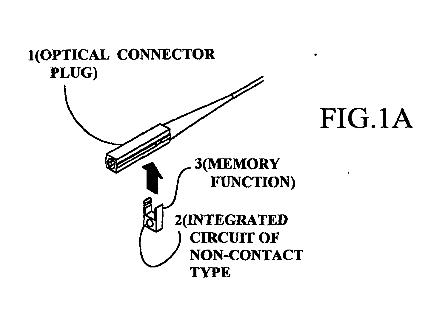
- An optical connector 10 with memory function of the present invention comprises, as illustrated in Fig.1A and Fig.1B, an optical connector plug 1 including an optical connection portion, and a memory function 3 having an integrated circuit of non-contact type, which is formed into an electromagnetic induction system applied to IC cards and IC fixed-term tickets developed as RFID (Radio Frequency Information Distributor) systems.
- a read-write device comprises, as shown in Fig.2, an antenna 4 having electromagnetic induction coupling to the integrated circuit 2 of non-contact type, and a controller 5 provided for controlling the antenna 4.
- the controller 5 communicates to the memory function 3 of the side of the optical connector 10 by way of the antenna 4 positioned near the adapter 6 to perform the reading-out and writing-in of necessary information, so that the device operates as the optical connector 10 with memory function.
- peculiar ID peculiar identification information
- the object of the present invention is attainable by providing the optical connector 10 with memory function as mentioned above.
- the followings are concrete application examples in correspondence to the objects of the present invention.
- the peculiar ID is read in the memory function 3 of the optical connector plug 1, while contents of the working steps and the working date and time are additionally applied to a computer 16, such as a personal computer (referred to "PC"), so that unitary control of respective working steps can be performed. Therefore, each item of the working date and time, the worker and the working step name, etc. can be readily pursued from the peculiar ID to enhance the transmission quality of the optical connector plug 1.
- a computer 16 such as a personal computer (referred to "PC")
- the peculiar ID is automatically read out from the memory function 3 of the optical connector plug 1 in each working step and then automatically read out by the antenna 4 to the controller 5 to supply the same to the computer 16.
- the above-mentioned erroneous inputting of the control information and overlook of read-in operation of the control information can be effectively eliminated.
- the present invention can be effectively applicable to a measurement operation of insertion loss.
- a light source 11, a master cable 12, a master adapter 13, a tested cable 14 to be measured and a light power meter 15 are employed as illustrated in Fig.3 and Fig.4.
- the light power meter 15 has outer connection means in order to be readable the indicated information thereof by the computer 16.
- the optical connector 10 with memory function according to the present invention to the memory function 3 of which the peculiar ID is read in.
- a standard value is at first measured.
- the light source 11, the master cable 12 and the light power meter 15 are mutually connected as illustrated in Fig.3.
- the indication value of the light power meter 15 of this condition is stored, as the standard value, in the computer 16 through the outer connection means.
- a series connection of the master adapter 13 and the tested cable 14 are inserted between the light power meter 15 and the master cable 12.
- the antenna 4 of the controller 5 is mounted on the master adapter 13 for reading-out and writing-in control information in relation to the memory function 3, and the optical connector 10 with memory function is connected to one end of the tested cable 14.
- the peculiar ID is read out from the memory function 3 of the optical connector 10 by the controller 5 through the antenna 4 and then stored to the computer 16.
- the indication value of the light power meter 15 is read out to the computer 16 through the outer connection means.
- An insertion loss characteristic of the optical connector 1 can be obtained by subtracting the standard value from the indication value.
- the peculiar ID and the insertion loss of the tested cable 14 are stored in relation to each other, so that a characteristic of the tested cable 14, to which the optical connector 10 is connected, can be effectively controlled.
- the optical connector provided in accordance with the present invention has a miniaturized formation which is readily operable without any troublesome.
- readout means is directly connected to the computer to apply automatically the control information thereto, the control information can be reliably controlled without any human operation, which accompanies with miss inputting of the control information.
Landscapes
- Physics & Mathematics (AREA)
- General Physics & Mathematics (AREA)
- Optics & Photonics (AREA)
- Engineering & Computer Science (AREA)
- Computer Hardware Design (AREA)
- Microelectronics & Electronic Packaging (AREA)
- Theoretical Computer Science (AREA)
- Mechanical Coupling Of Light Guides (AREA)
- Coupling Device And Connection With Printed Circuit (AREA)
Abstract
Description
- The present invention relates to an optical connector, and, especially, to an optical connector with memory function for control information.
- On many conventional optical connectors, a label or a tape, on which optional letters or bar codes are recorded, is pasted for individual control information. In other examples, grouped control information, such as lot numbers or manufactured dates, is recorded.
- In case of controlling production steps or mounting and wiring steps of optical connectors in these conditions, such control operations are usually performed by the use of computers. In this case, mistake such as erroneous understanding or erroneous inputting of control information shall be occasionally occurred, if letters are employed as the control information, since an operator performs the inputting operations in reading of the letters of control information.
- On the other hand, in a case where the control information of bar code is recorded, read-in operations are essential before and after a working operation step, while erroneous understanding or erroneous inputting of control information is especially reduced. Accordingly, if the read-in operation is overlooked at a working operation step, reliable control of this working operation step cannot be performed.
- Moreover, when the control information is recorded on a label or a tape, each of the label and the tape has to have an appropriate size for recognizing the control information. In this case where optical connectors carrying control information of these label and tape are accumulated on a distributing board in a real application circumstance, the label itself becomes considerable obstacle for freely manipulation so that the convenience of operation using the control information of this type is disturbed.
- Furthermore, if material of the label and the tape is of paper, the label and the tape may be damaged, so that the control information cannot be recognized and then controlled.
- An object of the present invention is to provide an optical connector with memory function, which comprises the memory function for storing respective identification information in order to readily and exactly perform separate control of respective control steps and further to obtain convenient handling of connectors.
- To attain the above object and other objects of the present invention, the optical connector with memory function of the present invention comprises an optical connector plug and an adapter provided to be coupled to said optical connector plug. The optical connector with memory function further comprises memory function capable of untouchably performing writing-in and reading-out of necessary information from outside thereof.
- The memory function has an integrated circuit formed into an electromagnetic induction system.
- The memory function has a structure mounted on or mountable on the outer construction of a housing accommodating therein the optical connection portion of the optical connector plug.
- An antenna is mounted on the adapter to electromagnetic -inductively couple to the integrated circuit.
- The present invention will be described in details below with reference to accompanying drawings, in which :
- Fig.1A is a perspective view illustrating construction examples of respective parts of basic examples of the optical connector plug employed in the present invention;
- Fig.1B is a perspective view illustrating a combined example of the respective parts of the optical connector with memory function of the present invention;
- Fig.2 is a connection diagram of respective devices explanatory of an application state of the optical connector with memory function of the present invention;
- Fig.3 is a connection diagram of respective devices explanatory of measurement of a standard value in case of measuring an insertion loss characteristic of the optical connector with memory function of the present invention; and
- Fiig.4 is a connection diagram of respective devices explanatory of input and output operations of identification information in the optical connector with memory function of the present invention.
-
- The present invention will be more precisely described with reference to accompanying drawings.
- An
optical connector 10 with memory function of the present invention comprises, as illustrated in Fig.1A and Fig.1B, anoptical connector plug 1 including an optical connection portion, and amemory function 3 having an integrated circuit of non-contact type, which is formed into an electromagnetic induction system applied to IC cards and IC fixed-term tickets developed as RFID (Radio Frequency Information Distributor) systems. Moreover, a read-write device comprises, as shown in Fig.2, anantenna 4 having electromagnetic induction coupling to the integratedcircuit 2 of non-contact type, and acontroller 5 provided for controlling theantenna 4. - When the
optical connector plug 1 is inserted into anadapter 6 as shown in Fig.2, thecontroller 5 communicates to thememory function 3 of the side of theoptical connector 10 by way of theantenna 4 positioned near theadapter 6 to perform the reading-out and writing-in of necessary information, so that the device operates as theoptical connector 10 with memory function. - Into the
memory function 3 of theoptical connector 10 with memory function, peculiar identification information (hereinafter referred to "peculiar ID") is previously stored. This identification information is a unique one so that there do not two of the same identification information. - The object of the present invention is attainable by providing the
optical connector 10 with memory function as mentioned above. The followings are concrete application examples in correspondence to the objects of the present invention. - In an optional one of working steps for mounting an
optical fiber 7 on theoptical connector plug 1, the peculiar ID is read in thememory function 3 of theoptical connector plug 1, while contents of the working steps and the working date and time are additionally applied to acomputer 16, such as a personal computer (referred to "PC"), so that unitary control of respective working steps can be performed. Therefore, each item of the working date and time, the worker and the working step name, etc. can be readily pursued from the peculiar ID to enhance the transmission quality of theoptical connector plug 1. - The peculiar ID is automatically read out from the
memory function 3 of theoptical connector plug 1 in each working step and then automatically read out by theantenna 4 to thecontroller 5 to supply the same to thecomputer 16. In this application II, the above-mentioned erroneous inputting of the control information and overlook of read-in operation of the control information can be effectively eliminated. - The present invention can be effectively applicable to a measurement operation of insertion loss. In this application, a
light source 11, amaster cable 12, amaster adapter 13, a testedcable 14 to be measured and alight power meter 15 are employed as illustrated in Fig.3 and Fig.4. Thelight power meter 15 has outer connection means in order to be readable the indicated information thereof by thecomputer 16. Moreover, to the testedcable 14 is mounted theoptical connector 10 with memory function according to the present invention, to thememory function 3 of which the peculiar ID is read in. - In this application III, a standard value is at first measured. To this end, the
light source 11, themaster cable 12 and thelight power meter 15 are mutually connected as illustrated in Fig.3. The indication value of thelight power meter 15 of this condition is stored, as the standard value, in thecomputer 16 through the outer connection means. - To measure the insertion loss, a series connection of the
master adapter 13 and the testedcable 14 are inserted between thelight power meter 15 and themaster cable 12. In this case, theantenna 4 of thecontroller 5 is mounted on themaster adapter 13 for reading-out and writing-in control information in relation to thememory function 3, and theoptical connector 10 with memory function is connected to one end of the testedcable 14. When the testedcable 14 is connected as illustrated in Fig.4, the peculiar ID is read out from thememory function 3 of theoptical connector 10 by thecontroller 5 through theantenna 4 and then stored to thecomputer 16. - When the tested
cable 14 is connected as illustrated in Fig.4, the indication value of thelight power meter 15 is read out to thecomputer 16 through the outer connection means. An insertion loss characteristic of theoptical connector 1 can be obtained by subtracting the standard value from the indication value. - As mentioned above, the peculiar ID and the insertion loss of the tested
cable 14 are stored in relation to each other, so that a characteristic of the testedcable 14, to which theoptical connector 10 is connected, can be effectively controlled. - As described in details above, since the memory function and the connector is formed into unitary structure in accordance with the present invention, the optical connector provided in accordance with the present invention has a miniaturized formation which is readily operable without any troublesome. Moreover, readout means is directly connected to the computer to apply automatically the control information thereto, the control information can be reliably controlled without any human operation, which accompanies with miss inputting of the control information.
Claims (3)
- An optical connector with memory function, comprising an optical connector plug and an adapter provided to be coupled to said optical connector plug,
said optical connector with memory function further comprising memory function capable of untouchably performing, from outside thereof, writing-in and reading-out of necessary control information. - An optical connector with memory function according to claim 1, in which said memory function is mounted on a housing accommodating therein an optical connection portion of the optical connector plug.
- An optical connector with memory function according to claim 1, in which said memory function has a structure mountable on the outer construction of a housing accommodating therein an optical connection portion of the optical connector plug.
Applications Claiming Priority (3)
| Application Number | Priority Date | Filing Date | Title |
|---|---|---|---|
| JP2002005642 | 2002-01-15 | ||
| JP2002005642A JP3776356B2 (en) | 2002-01-15 | 2002-01-15 | Optical connector with memory function |
| PCT/JP2003/000082 WO2003060582A1 (en) | 2002-01-15 | 2003-01-08 | Optical connector having memory function |
Publications (2)
| Publication Number | Publication Date |
|---|---|
| EP1467232A1 true EP1467232A1 (en) | 2004-10-13 |
| EP1467232A4 EP1467232A4 (en) | 2005-04-13 |
Family
ID=19191130
Family Applications (1)
| Application Number | Title | Priority Date | Filing Date |
|---|---|---|---|
| EP03700495A Withdrawn EP1467232A4 (en) | 2002-01-15 | 2003-01-08 | OPTICAL CONNECTOR WITH MEMORY FUNCTION |
Country Status (5)
| Country | Link |
|---|---|
| US (1) | US7210858B2 (en) |
| EP (1) | EP1467232A4 (en) |
| JP (1) | JP3776356B2 (en) |
| CA (1) | CA2439567A1 (en) |
| WO (1) | WO2003060582A1 (en) |
Cited By (16)
| Publication number | Priority date | Publication date | Assignee | Title |
|---|---|---|---|---|
| WO2011047288A1 (en) * | 2009-10-16 | 2011-04-21 | Adc Telecommunications, Inc. | Managed connectivity in fiber optic systems and methods thereof |
| WO2011100634A3 (en) * | 2010-02-12 | 2011-11-17 | Adc Telecommunications, Inc. | Managed fiber connectivity systems |
| EP2087567A4 (en) * | 2006-10-31 | 2012-10-10 | Corning Cable Sys Llc | Radio frequency identification of component connections |
| US8731405B2 (en) | 2008-08-28 | 2014-05-20 | Corning Cable Systems Llc | RFID-based systems and methods for collecting telecommunications network information |
| US8757895B2 (en) | 2011-04-15 | 2014-06-24 | Adc Telecommunications, Inc. | Managed fiber connectivity systems |
| US8897637B2 (en) | 2009-04-22 | 2014-11-25 | Adc Gmbh | Method and arrangement for identifying at least one object |
| US9064022B2 (en) | 2011-05-17 | 2015-06-23 | Adc Telecommunications, Inc. | Component identification and tracking system for telecommunication networks |
| US9219543B2 (en) | 2012-07-11 | 2015-12-22 | Commscope Technologies Llc | Monitoring optical decay in fiber connectivity systems |
| US9285552B2 (en) | 2013-02-05 | 2016-03-15 | Commscope Technologies Llc | Optical assemblies with managed connectivity |
| US9379501B2 (en) | 2013-02-05 | 2016-06-28 | Commscope Technologies Llc | Optical assemblies with managed connectivity |
| US9423570B2 (en) | 2013-02-05 | 2016-08-23 | Commscope Technologies Llc | Optical assemblies with managed connectivity |
| US9453971B2 (en) | 2012-07-11 | 2016-09-27 | Commscope Technologies Llc | Managed fiber connectivity systems |
| US9470742B2 (en) | 2012-08-03 | 2016-10-18 | Commscope Technologies Llc | Managed fiber connectivity systems |
| US9500814B2 (en) | 2014-03-26 | 2016-11-22 | Commscope Technologies Llc | Optical adapter module with managed connectivity |
| US9563832B2 (en) | 2012-10-08 | 2017-02-07 | Corning Incorporated | Excess radio-frequency (RF) power storage and power sharing RF identification (RFID) tags, and related connection systems and methods |
| US9798096B2 (en) | 2014-02-07 | 2017-10-24 | Commscope Technologies Llc | Managed fiber connectivity systems |
Families Citing this family (50)
| Publication number | Priority date | Publication date | Assignee | Title |
|---|---|---|---|---|
| JP3745728B2 (en) * | 2002-11-15 | 2006-02-15 | 東京通信機工業株式会社 | Adapter for memory function connector |
| US7243837B2 (en) * | 2004-04-02 | 2007-07-17 | Stratos International, Inc. | Media converter RFID security tag |
| US7165728B2 (en) * | 2004-04-02 | 2007-01-23 | Stratos International, Inc. | Radio frequency identification for transfer of component information in fiber optic testing |
| WO2007138694A1 (en) * | 2006-05-31 | 2007-12-06 | Hitachi, Ltd. | Collation method |
| US20070285239A1 (en) * | 2006-06-12 | 2007-12-13 | Easton Martyn N | Centralized optical-fiber-based RFID systems and methods |
| US8421626B2 (en) * | 2006-10-31 | 2013-04-16 | Corning Cable Systems, Llc | Radio frequency identification transponder for communicating condition of a component |
| US7772975B2 (en) * | 2006-10-31 | 2010-08-10 | Corning Cable Systems, Llc | System for mapping connections using RFID function |
| US9652707B2 (en) | 2006-10-31 | 2017-05-16 | Fiber Mountain, Inc. | Radio frequency identification (RFID) connected tag communications protocol and related systems and methods |
| US9652709B2 (en) | 2006-10-31 | 2017-05-16 | Fiber Mountain, Inc. | Communications between multiple radio frequency identification (RFID) connected tags and one or more devices, and related systems and methods |
| US10032102B2 (en) | 2006-10-31 | 2018-07-24 | Fiber Mountain, Inc. | Excess radio-frequency (RF) power storage in RF identification (RFID) tags, and related systems and methods |
| US9652708B2 (en) | 2006-10-31 | 2017-05-16 | Fiber Mountain, Inc. | Protocol for communications between a radio frequency identification (RFID) tag and a connected device, and related systems and methods |
| US8264366B2 (en) * | 2009-03-31 | 2012-09-11 | Corning Incorporated | Components, systems, and methods for associating sensor data with component location |
| US8264355B2 (en) | 2006-12-14 | 2012-09-11 | Corning Cable Systems Llc | RFID systems and methods for optical fiber network deployment and maintenance |
| US7760094B1 (en) | 2006-12-14 | 2010-07-20 | Corning Cable Systems Llc | RFID systems and methods for optical fiber network deployment and maintenance |
| US7667574B2 (en) * | 2006-12-14 | 2010-02-23 | Corning Cable Systems, Llc | Signal-processing systems and methods for RFID-tag signals |
| US7547150B2 (en) * | 2007-03-09 | 2009-06-16 | Corning Cable Systems, Llc | Optically addressed RFID elements |
| US7965186B2 (en) | 2007-03-09 | 2011-06-21 | Corning Cable Systems, Llc | Passive RFID elements having visual indicators |
| US7715679B2 (en) | 2007-05-07 | 2010-05-11 | Adc Telecommunications, Inc. | Fiber optic enclosure with external cable spool |
| US7756379B2 (en) | 2007-08-06 | 2010-07-13 | Adc Telecommunications, Inc. | Fiber optic enclosure with internal cable spool |
| US7855697B2 (en) * | 2007-08-13 | 2010-12-21 | Corning Cable Systems, Llc | Antenna systems for passive RFID tags |
| US8248208B2 (en) | 2008-07-15 | 2012-08-21 | Corning Cable Systems, Llc. | RFID-based active labeling system for telecommunication systems |
| US20100079248A1 (en) * | 2008-09-29 | 2010-04-01 | Johannes Ian Greveling | Optical fiber connector assembly with wire-based RFID antenna |
| JP2009105958A (en) * | 2009-02-02 | 2009-05-14 | Kddi Corp | Optical connector |
| US8992260B2 (en) | 2009-10-16 | 2015-03-31 | Adc Telecommunications, Inc. | Managed connectivity in electrical systems and methods thereof |
| BR112012009258A2 (en) | 2009-10-19 | 2017-06-06 | Adc Telecommunications Inc | organized electrical connectivity systems |
| CN102045125B (en) * | 2009-10-26 | 2013-12-04 | 华为技术有限公司 | Optical splitter as well as optical splitter port identification method and device |
| EP2507746B1 (en) | 2009-11-30 | 2015-10-14 | Corning Incorporated | Rfid condition latching |
| US8172468B2 (en) | 2010-05-06 | 2012-05-08 | Corning Incorporated | Radio frequency identification (RFID) in communication connections, including fiber optic components |
| US8565572B2 (en) | 2010-06-23 | 2013-10-22 | Adc Telecommunications, Inc. | Telecommunications assembly |
| US8410909B2 (en) | 2010-07-09 | 2013-04-02 | Corning Incorporated | Cables and connector assemblies employing a furcation tube(s) for radio-frequency identification (RFID)-equipped connectors, and related systems and methods |
| US8696369B2 (en) | 2010-09-09 | 2014-04-15 | Adc Telecommunications, Inc. | Electrical plug with main contacts and retractable secondary contacts |
| US8992261B2 (en) | 2010-10-22 | 2015-03-31 | Adc Telecommunications, Inc. | Single-piece plug nose with multiple contact sets |
| US8715012B2 (en) | 2011-04-15 | 2014-05-06 | Adc Telecommunications, Inc. | Managed electrical connectivity systems |
| US20120274452A1 (en) * | 2011-04-26 | 2012-11-01 | Aravind Chamarti | Radio frequency (rf)-enabled latches and related components, assemblies, systems, and methods |
| US9223106B2 (en) | 2011-06-24 | 2015-12-29 | Commscope Technologies Llc | Fiber termination enclosure with modular plate assemblies |
| WO2013055591A2 (en) | 2011-10-07 | 2013-04-18 | Adc Telecommunications, Inc. | Fiber optic cassette, system, and method |
| US8622774B2 (en) | 2011-11-07 | 2014-01-07 | Delphi Technologies, Inc. | Electrical contact having channel with angled sidewalls and romboid knurl pattern |
| US9038141B2 (en) | 2011-12-07 | 2015-05-19 | Adc Telecommunications, Inc. | Systems and methods for using active optical cable segments |
| US9165232B2 (en) | 2012-05-14 | 2015-10-20 | Corning Incorporated | Radio-frequency identification (RFID) tag-to-tag autoconnect discovery, and related methods, circuits, and systems |
| WO2013176314A1 (en) * | 2012-05-24 | 2013-11-28 | (주)파이버피아 | Simplified optical fiber identifier |
| US9207417B2 (en) * | 2012-06-25 | 2015-12-08 | Adc Telecommunications, Inc. | Physical layer management for an active optical module |
| US9093796B2 (en) | 2012-07-06 | 2015-07-28 | Adc Telecommunications, Inc. | Managed electrical connectivity systems |
| US9203198B2 (en) | 2012-09-28 | 2015-12-01 | Commscope Technologies Llc | Low profile faceplate having managed connectivity |
| CN105324696B (en) | 2012-12-19 | 2019-05-17 | 泰科电子瑞侃有限公司 | Distribution device with progressively increasing splitters |
| CA2925446A1 (en) | 2013-09-24 | 2015-04-02 | Commscope Technologies Llc | Pluggable active optical module with managed connectivity support and simulated memory table |
| WO2016073494A1 (en) * | 2014-11-05 | 2016-05-12 | Commscope Technologies Llc | Connection trays with managed connectivity |
| WO2019018677A1 (en) * | 2017-07-19 | 2019-01-24 | Fiber Mountain, Inc. | Fiber connector assembly |
| JP6904147B2 (en) * | 2017-08-01 | 2021-07-14 | 株式会社オートネットワーク技術研究所 | Wire with terminal |
| US11150417B2 (en) * | 2019-09-06 | 2021-10-19 | Coming Research & Development Corporation | Systems and methods for estimating insertion loss in optical fiber connections and fiber links using data reading apparatus |
| US11624680B2 (en) * | 2020-09-10 | 2023-04-11 | Exfo Inc. | Optical fiber endface inspection microscope having adapter tip detection and autoconfiguration |
Family Cites Families (7)
| Publication number | Priority date | Publication date | Assignee | Title |
|---|---|---|---|---|
| JP2675366B2 (en) * | 1988-11-21 | 1997-11-12 | 日本電信電話株式会社 | Optical fiber connection status monitoring system |
| JPH05150143A (en) * | 1991-11-27 | 1993-06-18 | Sumitomo Electric Ind Ltd | Optical connector with built-in circuit |
| JPH0843527A (en) * | 1994-07-29 | 1996-02-16 | Nippon Avionics Co Ltd | Non-contact individual identification system |
| CA2162515C (en) * | 1994-12-22 | 2000-03-21 | Leonard George Cohen | Jumper tracing system |
| US5636020A (en) * | 1995-04-27 | 1997-06-03 | Lucent Technologies Inc. | Zone analysis system and method for optimizing the performance of an inspection system for determining disparity between two surfaces |
| JP2000277212A (en) * | 1999-03-23 | 2000-10-06 | Sumitomo Electric Ind Ltd | Code with connector and method of reading its identification symbol |
| DE10126351A1 (en) * | 2001-05-30 | 2002-12-12 | Ccs Technology Inc | Optical distribution device and fiber optic connection cable |
-
2002
- 2002-01-15 JP JP2002005642A patent/JP3776356B2/en not_active Expired - Fee Related
-
2003
- 2003-01-08 CA CA002439567A patent/CA2439567A1/en not_active Abandoned
- 2003-01-08 WO PCT/JP2003/000082 patent/WO2003060582A1/en not_active Ceased
- 2003-01-08 EP EP03700495A patent/EP1467232A4/en not_active Withdrawn
- 2003-09-15 US US10/662,669 patent/US7210858B2/en not_active Expired - Fee Related
Non-Patent Citations (2)
| Title |
|---|
| No further relevant documents disclosed * |
| See also references of WO03060582A1 * |
Cited By (55)
| Publication number | Priority date | Publication date | Assignee | Title |
|---|---|---|---|---|
| EP2087567A4 (en) * | 2006-10-31 | 2012-10-10 | Corning Cable Sys Llc | Radio frequency identification of component connections |
| US8731405B2 (en) | 2008-08-28 | 2014-05-20 | Corning Cable Systems Llc | RFID-based systems and methods for collecting telecommunications network information |
| US9058529B2 (en) | 2008-08-28 | 2015-06-16 | Corning Optical Communications LLC | RFID-based systems and methods for collecting telecommunications network information |
| US8897637B2 (en) | 2009-04-22 | 2014-11-25 | Adc Gmbh | Method and arrangement for identifying at least one object |
| WO2011047288A1 (en) * | 2009-10-16 | 2011-04-21 | Adc Telecommunications, Inc. | Managed connectivity in fiber optic systems and methods thereof |
| US9810860B2 (en) | 2009-10-16 | 2017-11-07 | Commscope Technologies Llc | Managed connectivity in fiber optic systems and methods thereof |
| US10678001B2 (en) | 2009-10-16 | 2020-06-09 | Commscope Technologies Llc | Managed connectivity in fiber optic systems and methods thereof |
| US8596882B2 (en) | 2009-10-16 | 2013-12-03 | Adc Telecommunications, Inc. | Managed connectivity in fiber optic systems and methods thereof |
| US11231555B2 (en) | 2009-10-16 | 2022-01-25 | Commscope Technologies Llc | Managed connectivity in fiber optic systems and methods thereof |
| US11630269B2 (en) | 2009-10-16 | 2023-04-18 | Commscope Technologies Llc | Managed connectivity in fiber optic systems and methods thereof |
| US9176294B2 (en) | 2009-10-16 | 2015-11-03 | Tyco Electronics Services Gmbh | Managed connectivity in fiber optic systems and methods thereof |
| US12235494B2 (en) | 2009-10-16 | 2025-02-25 | Commscope Technologies Llc | Managed connectivity in fiber optic systems and methods thereof |
| US9140859B2 (en) | 2010-02-12 | 2015-09-22 | Tyco Electronics Services Gmbh | Managed fiber connectivity systems |
| US10983285B2 (en) | 2010-02-12 | 2021-04-20 | Commscope Technologies Llc | Managed fiber connectivity systems |
| US11899246B2 (en) | 2010-02-12 | 2024-02-13 | Commscope Technologies Llc | Managed fiber connectivity systems |
| US12306444B2 (en) | 2010-02-12 | 2025-05-20 | Commscope Technologies Llc | Managed fiber connectivity systems |
| US11378755B2 (en) | 2010-02-12 | 2022-07-05 | Commscope Technologies Llc | Managed fiber connectivity systems |
| US8690593B2 (en) | 2010-02-12 | 2014-04-08 | Adc Telecommunications, Inc. | Managed fiber connectivity systems |
| US9417399B2 (en) | 2010-02-12 | 2016-08-16 | Commscope Technologies Llc | Managed fiber connectivity systems |
| CN102939553B (en) * | 2010-02-12 | 2015-05-20 | Adc电信公司 | Managed Fiber Connectivity System |
| CN102939553A (en) * | 2010-02-12 | 2013-02-20 | Adc电信公司 | Managed Fiber Connectivity System |
| US10473864B2 (en) | 2010-02-12 | 2019-11-12 | Commscope Technologies Llc | Managed fiber connectivity systems |
| US10088636B2 (en) | 2010-02-12 | 2018-10-02 | Commscope Technologies Llc | Managed fiber connectivity systems |
| WO2011100634A3 (en) * | 2010-02-12 | 2011-11-17 | Adc Telecommunications, Inc. | Managed fiber connectivity systems |
| US9632255B2 (en) | 2010-02-12 | 2017-04-25 | Commscope Technologies Llc | Managed fiber connectivity systems |
| US9684134B2 (en) | 2010-02-12 | 2017-06-20 | Commscope Technologies Llc | Managed fiber connectivity systems |
| US9804337B2 (en) | 2010-02-12 | 2017-10-31 | Commscope Technologies Llc | Managed fiber connectivity systems |
| US9759874B2 (en) | 2011-04-15 | 2017-09-12 | CommScope Technologies, LLC | Managed fiber connectivity systems |
| US9244229B2 (en) | 2011-04-15 | 2016-01-26 | Commscope Technologies Llc | Managed fiber connectivity systems |
| US8757895B2 (en) | 2011-04-15 | 2014-06-24 | Adc Telecommunications, Inc. | Managed fiber connectivity systems |
| US9064022B2 (en) | 2011-05-17 | 2015-06-23 | Adc Telecommunications, Inc. | Component identification and tracking system for telecommunication networks |
| US9453971B2 (en) | 2012-07-11 | 2016-09-27 | Commscope Technologies Llc | Managed fiber connectivity systems |
| US9219543B2 (en) | 2012-07-11 | 2015-12-22 | Commscope Technologies Llc | Monitoring optical decay in fiber connectivity systems |
| US10050703B2 (en) | 2012-07-11 | 2018-08-14 | Commscope Technologies Llc | Monitoring optical decay in fiber connectivity systems |
| US9470742B2 (en) | 2012-08-03 | 2016-10-18 | Commscope Technologies Llc | Managed fiber connectivity systems |
| US9563832B2 (en) | 2012-10-08 | 2017-02-07 | Corning Incorporated | Excess radio-frequency (RF) power storage and power sharing RF identification (RFID) tags, and related connection systems and methods |
| US9379501B2 (en) | 2013-02-05 | 2016-06-28 | Commscope Technologies Llc | Optical assemblies with managed connectivity |
| US9285552B2 (en) | 2013-02-05 | 2016-03-15 | Commscope Technologies Llc | Optical assemblies with managed connectivity |
| US12517310B2 (en) | 2013-02-05 | 2026-01-06 | Commscope Technologies Llc | Optical assemblies with managed connectivity |
| US11327248B2 (en) | 2013-02-05 | 2022-05-10 | Commscope Technologies Llc | Optical assemblies with managed connectivity |
| US9778424B2 (en) | 2013-02-05 | 2017-10-03 | Commscope Technologies Llc | Optical assemblies with managed connectivity |
| US10746943B2 (en) | 2013-02-05 | 2020-08-18 | Commscope Technologies Llc | Optical assemblies with managed connectivity |
| US9423570B2 (en) | 2013-02-05 | 2016-08-23 | Commscope Technologies Llc | Optical assemblies with managed connectivity |
| US11143833B2 (en) | 2013-02-05 | 2021-10-12 | Commscope Technologies Llc | Optical assemblies with managed connectivity |
| US9735523B2 (en) | 2013-02-05 | 2017-08-15 | Commscope Connectivity Uk Limited | Optical assemblies with managed connectivity |
| US10268000B2 (en) | 2013-02-05 | 2019-04-23 | Commscope Technologies Llc | Optical assemblies with managed connectivity |
| US10571641B2 (en) | 2013-02-05 | 2020-02-25 | Commscope Technologies Llc | Optical assemblies with managed connectivity |
| US12235505B2 (en) | 2013-02-05 | 2025-02-25 | Commscope Technologies Llc | Fiber optic cassette arrangement |
| US11714246B2 (en) | 2013-02-05 | 2023-08-01 | Commscope Technologies Llc | Optical assemblies with contoured base |
| US11867952B2 (en) | 2013-02-05 | 2024-01-09 | Commscope Technologies Llc | Optical assemblies with managed connectivity |
| US10012813B2 (en) | 2013-02-05 | 2018-07-03 | Commscope Technologies Llc | Optical assemblies with managed connectivity |
| US9798096B2 (en) | 2014-02-07 | 2017-10-24 | Commscope Technologies Llc | Managed fiber connectivity systems |
| US9995883B2 (en) | 2014-03-26 | 2018-06-12 | Commscope Technologies Llc | Optical adapter module with managed connectivity |
| US9500814B2 (en) | 2014-03-26 | 2016-11-22 | Commscope Technologies Llc | Optical adapter module with managed connectivity |
| US10509177B2 (en) | 2014-03-26 | 2019-12-17 | Commscope Technologies Llc | Optical adapter module with managed connectivity |
Also Published As
| Publication number | Publication date |
|---|---|
| US20040120657A1 (en) | 2004-06-24 |
| US7210858B2 (en) | 2007-05-01 |
| EP1467232A4 (en) | 2005-04-13 |
| JP2003207686A (en) | 2003-07-25 |
| JP3776356B2 (en) | 2006-05-17 |
| CA2439567A1 (en) | 2003-07-24 |
| WO2003060582A1 (en) | 2003-07-24 |
Similar Documents
| Publication | Publication Date | Title |
|---|---|---|
| EP1467232A1 (en) | Optical connector having memory function | |
| US7336883B2 (en) | Indexing optical fiber adapter | |
| US7226217B1 (en) | Transceiver/fiber optic connector adaptor with patch cord ID reading capability | |
| US5910776A (en) | Method and apparatus for identifying locating or monitoring equipment or other objects | |
| CN100492983C (en) | Self-registration system and method for dynamically updating network-related information | |
| US6989749B2 (en) | Electronic check out system | |
| US7468669B1 (en) | RFID patch panels and cables | |
| US6808116B1 (en) | Fiber jumpers with data storage method and apparatus | |
| EP0597373A1 (en) | Data input device for IC-key lock system | |
| JP3814613B2 (en) | Wiring connection management system | |
| US20140197930A1 (en) | Field Device for Automation Technology | |
| WO2003063315A1 (en) | Identification tag for linear body, device and method for fixing the tag, connector arrangement control method, connector arrangement tool, linear body with connector, and connector receiving plug terminal panel | |
| GB2406951A (en) | Flexible loyalty points management for gaming machines | |
| JP2005092107A (en) | Management system of transmission component using connector plug with memory | |
| US7623980B2 (en) | Measuring device with evaluation unit and external memory | |
| JP3986277B2 (en) | Signal transmission line identification device | |
| EP0858046A3 (en) | Method and apparatus for integrated circuit card | |
| GB2185134A (en) | Memory package | |
| US11415550B2 (en) | Sensor and processing part for a sensor | |
| JPH03248287A (en) | Bar code reader | |
| US20050166689A1 (en) | Mark provided in an environment to be measured and measuring system comprising same | |
| JP4520759B2 (en) | Meter device and meter management system using the same | |
| JP2024117966A (en) | Cable connection check device, cable connection check method, and program | |
| JP2003110300A (en) | Printed circuit board | |
| AU664338B2 (en) | Wool bale labelling and inventory system |
Legal Events
| Date | Code | Title | Description |
|---|---|---|---|
| PUAI | Public reference made under article 153(3) epc to a published international application that has entered the european phase |
Free format text: ORIGINAL CODE: 0009012 |
|
| 17P | Request for examination filed |
Effective date: 20030806 |
|
| AK | Designated contracting states |
Kind code of ref document: A1 Designated state(s): AT BE BG CH CY CZ DE DK EE ES FI FR GB GR HU IE IT LI LU MC NL PT SE SI SK TR |
|
| AX | Request for extension of the european patent |
Extension state: AL LT LV MK RO |
|
| A4 | Supplementary search report drawn up and despatched |
Effective date: 20050302 |
|
| RIC1 | Information provided on ipc code assigned before grant |
Ipc: 7G 02B 6/38 A |
|
| 17Q | First examination report despatched |
Effective date: 20060803 |
|
| STAA | Information on the status of an ep patent application or granted ep patent |
Free format text: STATUS: THE APPLICATION IS DEEMED TO BE WITHDRAWN |
|
| 18D | Application deemed to be withdrawn |
Effective date: 20080801 |