EP1463342A1 - Test system for camera modules - Google Patents
Test system for camera modules Download PDFInfo
- Publication number
- EP1463342A1 EP1463342A1 EP03392003A EP03392003A EP1463342A1 EP 1463342 A1 EP1463342 A1 EP 1463342A1 EP 03392003 A EP03392003 A EP 03392003A EP 03392003 A EP03392003 A EP 03392003A EP 1463342 A1 EP1463342 A1 EP 1463342A1
- Authority
- EP
- European Patent Office
- Prior art keywords
- test
- focus
- level
- sub
- window
- Prior art date
- Legal status (The legal status is an assumption and is not a legal conclusion. Google has not performed a legal analysis and makes no representation as to the accuracy of the status listed.)
- Withdrawn
Links
- 238000012360 testing method Methods 0.000 title claims abstract description 84
- 238000000034 method Methods 0.000 claims abstract description 47
- 230000003287 optical effect Effects 0.000 claims abstract description 30
- 239000003292 glue Substances 0.000 claims abstract description 13
- 239000000428 dust Substances 0.000 claims abstract description 12
- 239000002245 particle Substances 0.000 claims abstract 3
- 239000000523 sample Substances 0.000 claims description 19
- 238000005259 measurement Methods 0.000 claims description 10
- 238000007789 sealing Methods 0.000 claims description 9
- 238000003708 edge detection Methods 0.000 claims description 7
- 229920006395 saturated elastomer Polymers 0.000 claims description 5
- 238000004458 analytical method Methods 0.000 claims description 4
- 238000003491 array Methods 0.000 claims description 4
- 238000012935 Averaging Methods 0.000 claims description 3
- 239000003086 colorant Substances 0.000 claims description 3
- 239000011521 glass Substances 0.000 claims description 3
- 239000002184 metal Substances 0.000 claims description 2
- GCKMFJBGXUYNAG-HLXURNFRSA-N Methyltestosterone Chemical compound C1CC2=CC(=O)CC[C@]2(C)[C@@H]2[C@@H]1[C@@H]1CC[C@](C)(O)[C@@]1(C)CC2 GCKMFJBGXUYNAG-HLXURNFRSA-N 0.000 claims 1
- 229940085503 testred Drugs 0.000 claims 1
- 229920001690 polydopamine Polymers 0.000 abstract description 3
- 238000005286 illumination Methods 0.000 description 3
- 238000003384 imaging method Methods 0.000 description 3
- 239000012780 transparent material Substances 0.000 description 3
- 238000005305 interferometry Methods 0.000 description 2
- 230000003595 spectral effect Effects 0.000 description 2
- 238000013459 approach Methods 0.000 description 1
- 230000005540 biological transmission Effects 0.000 description 1
- 230000001427 coherent effect Effects 0.000 description 1
- 238000013461 design Methods 0.000 description 1
- 238000001514 detection method Methods 0.000 description 1
- 239000000463 material Substances 0.000 description 1
- 238000010606 normalization Methods 0.000 description 1
- 238000010183 spectrum analysis Methods 0.000 description 1
Images


Classifications
-
- H—ELECTRICITY
- H04—ELECTRIC COMMUNICATION TECHNIQUE
- H04N—PICTORIAL COMMUNICATION, e.g. TELEVISION
- H04N17/00—Diagnosis, testing or measuring for television systems or their details
- H04N17/002—Diagnosis, testing or measuring for television systems or their details for television cameras
-
- H—ELECTRICITY
- H04—ELECTRIC COMMUNICATION TECHNIQUE
- H04N—PICTORIAL COMMUNICATION, e.g. TELEVISION
- H04N23/00—Cameras or camera modules comprising electronic image sensors; Control thereof
- H04N23/57—Mechanical or electrical details of cameras or camera modules specially adapted for being embedded in other devices
Definitions
- the invention relates to a test system for digital miniature camera modules, and more particularly, to a system to test camera modules, to be used as built-in modules in consumer electronics as e.g. mobile phones or PDAs, performing electrical tests, adjustment of the focus, and sealing the lens barrel with glue.
- a typical requirement for a mobile phone camera is good focus between 0.4 m and infinity.
- the term depth-of-field refers to a range over which the object can be moved and still be imaged with a blur not exceeding the acceptable one. For a fixed-focus camera having the requirement of a focus up to infinity the needed focus distance is called hyper-focal distance.
- U. S. Patent 6,512,587 (to Marcus et al.) describes a method for determining whether an imager assembly outside of a camera body meets predetermined focus specifications, wherein the imager assembly includes an image sensor and a camera mounting plate having reference features adapted to cooperate with alignment features in the camera body to locate the image sensor at a predetermined focal plane, including the steps of: mounting the imager assembly onto an imager mounting apparatus having equivalent alignment features; and utilizing low-coherence light interferometry to determine whether the image sensor will meet predetermined focus specifications when mounted in a camera body.
- U. S. Patent 6,075,601 discloses an apparatus and method for calibrating an optical probe assembly, wherein the optical probe assembly includes a probe mounting surface and an optically transparent material spaced from the probe-mounting surface.
- the method includes providing a calibration apparatus, wherein the calibration apparatus includes a calibration mount having an axis and a reference surface on an exterior surface of the calibration mount.
- a calibration target is mounted substantially perpendicular to the calibration mount axis at a predetermined distance from the calibration mount reference surface, and a distance LR from the calibration target to the calibration mount reference surface is determined.
- the optical probe assembly is then removably mounted and lockably secured to the calibration apparatus such that the calibration mount reference surface is in a predetermined orientation relative to the probe-mounting surface on the optical probe assembly.
- Non-coherent light interferometry is used to determine a distance PR from the optically transparent material to the calibration target, and a distance LP from the probe-mounting surface to the optically transparent material using the values of LR and PR is determined.
- a principal object of the present invention is to achieve a test system and a related method to test cost-efficiently digital fixed-focus cameras.
- a further object of the present invention is to combine the sealing of the lens with the focusing and electrical and optical test of said cameras.
- a system to perform optical and electrical tests, to adjust the focus and to seal the lens of digital fixed-focus cameras comprises a control system having interfaces to a robot system and to means for executing optical and electrical tests, focusing and sealing of a lens, a means of executing optical and electrical tests and focusing and sealing a lens, being controlled by said control system, comprising a fixed and a rotatable part, wherein said fixed part is comprising a light source, optical lenses, two diffusers, a test pattern, electrical connections, a glue dispenser, height gauges, and wherein the rotatable part, holding the camera module to be tested, is comprising electrical probes and a means to move and to adjust the focus of said camera modules by moving the lens barrel; and a means to move the camera modules to be tested.
- a method to perform optical and electrical tests, to adjust the focus and to seal the lens of digital fixed-focus cameras comprises, first, providing a control system, a means of executing optical and electrical tests and focusing and sealing a lens, comprising a fixed and a rotatable part, wherein said fixed part is comprising a light source, optical lenses, a fixed and a removable diffuser, a test pattern, electrical connections, a glue dispenser, height gauges, and wherein the rotatable part, holding the camera module to be tested, is comprising electrical probes and a means of performing the movements of the camera modules to be tested.
- the steps of the method invented comprise, first, to adjust the focus of the camera module, to analyze said focus, to set the lens grip free, to inset a diffuser and to identify hot pixels and black level.
- the following steps comprise to test the saturation level, to identify hot pixels, to test dust, to test white, infrared, blue and red level, and finally to apply glue.
- test system may either connect to a single module or modules mounted on panels
- Fig. 1 shows the test system invented comprising three basic elements, namely an auto-focus head 1, a XYZ robot 2 and a PC-based control system 3.
- Said test system is able to perform a variety of optical tests and additionally it performs electrical tests, the adjustment of the focus and the sealing of the lens barrel with glue.
- Said PC-based control system 3 is comprising in a preferred embodiment an RS232 interface 4 to the XYZ robot 2, a digital I/O interface 5 and an l2C bus 6 to the auto focus head 1, and a frame grabber card 7 receiving input from said auto focus head.
- a frame grabber 7 is a device that can seize and record a single frame of image information out of a sequence of many frames.
- An l2C 6 bus is a two-wire serial bus used extensively in a variety of microcontroller-based professional, consumer and telecommunications applications as a control, diagnostic and power management bus. Said l2C bus is used here to communicate with the camera module and to bring it in different test modes and settings.
- Said XYZ-robot 2 used moves in three different directions controlled by said PC-based control system 3.
- the XY-directions make it possible to move between the different camera modules on a panel or between different panels.
- the Z-direction is used to approach the lens system.
- An additional rotating movement adjusts the focus setting by turning the lens.
- the XYZ-robot and the additional devices as stepper motors, hoods etc. are standard off-the shelf devices, and they have all required security functionality included.
- the interface between the XYZ robot 2 and the PC-based control system 3 is of RS232 type 4 and a local motor control device 8 executes the commands sent to it. This device also provides a number of general purpose digital I/Os. Mechanical interfaces 9 are provided between the XYZ robot 2 and the auto focus head 1 . The operating area of the machine will be covered by a hood to ensure staff security, to control the light flow, and to keep dust out of the working area (filtered compressed air if needed).
- the optical part of the test system is used to focus and to test the imaging performance of camera modules either singulated or mounted on panels.
- Fig. 2 shows a schematic of the basic parts of the auto focus head used.
- Said auto focus head consists of two sections, one fixed 29 and one rotatable part 28 .
- the rotatable 28 part is connected via a transmission to a stepper motor being a part of the XYZ-robot system described above.
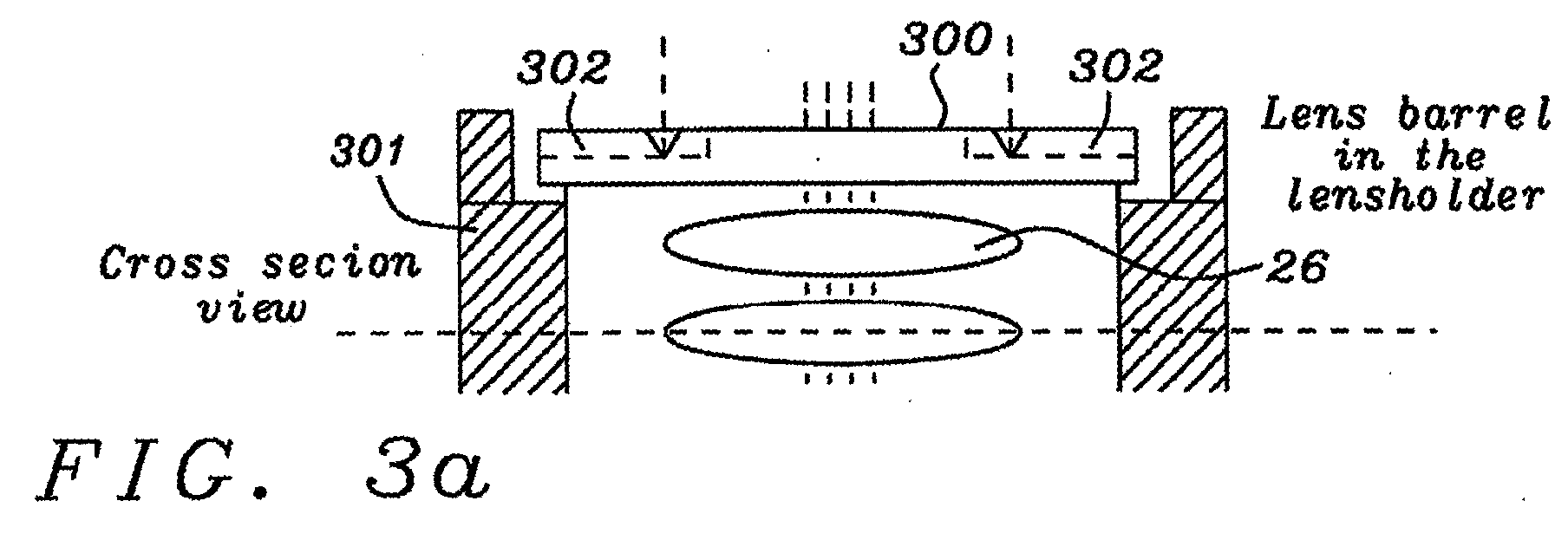
- FIG. 3a a cross section view of a part of a camera module to be tested is illustrated.
- Fig. 3a shows a lens barrel 300 being surrounded of a lens holder 301 .
- Several dents 302 are provided at the top of said lens barrel 300 .
- Said dents 302 serve as counterpart of adaptors 303 protruding the bottom side of a focusing grip 304 as shown in the cross section view of Fig. 3b .
- Said adaptors 303 and the dents 302 on the surface of the lens barrel 300 match in a way that the adaptors 303 can "key" into the matching dents 302 and can move said lens barrel 300 to set the lens barrel into focus.
- Fig. 3C shows the bottom side of said lens grip 304 , showing four adaptors 303 , matching the dents 302 shown in Fig. 3a .
- Fig. 3C shows the bottom side of said lens grip 304 , showing four adaptors 303 , matching the dents 302 shown in Fig. 3a .
- the focusing grip being a replaceable part of the focus head will hook into the lens barrel when the auto focus head descends over the camera module 25 .
- Said rotatable section 28 adapts to the lens-focusing grip of the module.
- An algorithm of the PC-based control system uses a live picture from the camera module 25 to decide how to turn the lens 26 .
- Said stepper motor carries out the rotation.
- the fixed part 29 includes a light source 20 , optical lenses 23 , diffusers 21 and 24 , electrical connections, glue dispensers 30 , height gauges 31 and 32 , etc.
- the lens adjustment and means for the electrical connections and distance measurements are fitted together with the glue dispenser 30 in the auto focus head.
- the head is mounted on a XYZ conveyor, which is part of the XYZ-robot system described above.
- the optics of the test system consists of a light source 20 , comprising four color LEDs, a first diffuser 21 for said light source, a transparent target 22 , an imaging lens system 23 and a second removable diffuser 24 .
- Said LED light source 20 comprises arrays of LEDs with different wavelengths as e.g. blue (B), white (W), red (R), and infrared (IR) arranged in such a pattern that the diffuser 21 can be well and uniformly illuminated by either color.
- the light intensity and emitted colors are parameters controlled by the PC-based control system 3, shown in Fig. 1.
- the diffuser D1 21 uniforms the light intensity over the transparent target test pattern 22.
- said transparent target 22 consists of black and white squares or similar in a checkerboard pattern etched in a glass lid.
- Said pattern is achieved by a very thin metallic plate with square or round holes.
- the plate is attached to a glass lid.
- This arrangement provides the system with an optimal contrast.
- the area of the holes is approximately equal the area of the metal. It is desirable to have as many transactions between white and black as possible.
- Each square has in a preferred embodiment a side of about 20 pixels when imaged by the camera module 25 to be tested.
- the target is large enough to fill the whole field-of-view.
- the system is calibrated using a "golden” sample camera module that is pre-focused at a defined distance close to the hyper-focal distance.
- the distance between the target 22 and the imaging lens 12 should be adjusted so that the pre-focused "golden” camera will give images of the target in perfect focus.
- the purpose of the secondary removable diffuser D2 24 is to illuminate the sensor 27 with nearly homogenous light to measure if the lens system and sensor is clean, if cold pixels are present, and the spectral response. using LEDs of the light source 20 .
- the detection of dust and of cold pixels is performed using white light while the spectral response is measured using all four different colors, white, blue red, and infrared, of the light source 20 .
- the electrical connection is achieved via probing needles 33 . Every signal from the flexi-strip is connected. For panel-mounted camera modules it is possible to probe "internal signals" of the camera module 25 .
- a level sensor 31 measures the current distance between the auto focus head 1 and the lens 26 of the camera module.
- Another level sensor 32 measures the current distance between the auto focus head and the image plane 34 . Said measurement prevents damage of the lens and of the module itself. The difference of the measurement of both gauges 31 and 32 indicates the current distance from the image plane to the top of the lens.
- the glue dispenser 30 dispenses the glue when the focus setting is finished and approved.
- the tests of the camera units are performed generally using an image processor as part of the camera module.
- Said processor is set up to provide a Quarter Video Graphics Array (QVGA) output of maximum color depth for red (R), green (G), and blue (B) having each (6, 6, 5) bits.
- QVGA Quarter Video Graphics Array
- an image processor is used capable to handle up to 30 frames per second (fps).
- fps frames per second
- Fig. 4 shows the well-known Bayer pattern comprising the locations and the distribution of R, G1, G2 and B. If another image is taken with a shift of 1 pixel left/right and a shift of 1 pixel up/down also G2 can be measured. Said shift is used to identify bad pixels.
- Fig. 5 shows the steps of the method invented to test a fixed focus camera including to set and to fix the focus of said camera.
- the first step 51 of the flowchart of Fig. 5 action is to adjust the focus of the camera module to be tested.
- Said step is performed using diffuser D1 21 shown in Fig. 2 and a white light source.
- a test window of 100 x 100 pixels in the green channel of said QVGA image of said image processor is used.
- a standard Sobel edge detection operator is used to generate an estimate of the edge content of the test window.
- Said Sobel edge detection produces an image where higher grey-level values indicate the presence of an edge between two objects.
- the Sobel Edge Detection operator computes the root mean square of two 3X3 templates.
- other edge detection methods could be used as well, as e.g. Canny-, Prewitt compass-, or Roberts edge detection method.
- the sum of the pixel values are taken and measured at a multitude of the current focus positions.
- the lens position giving the highest possible focus value is the correct focus position.
- the following step 52 covers the analysis of the focus. Said step is performed using diffuser D1 21 shown in Fig. 2 and a white light source.
- For the image obtained at best possible focus (as described above) five sub-windows are being analyzed. They are e.g. 100 x 100 pixel windows located at the corners and in the middle of the image. Each sub-image is normalized by its average brightness by dividing each pixel value by the measured average value. After normalization each window is measured the same way as during the above-described adjustment of focusing. The focus measurements are compared with the same measurements for the golden sample. Units showing a difference larger than the tolerances are rejected.
- step 53 the head has to be put in a certain position before the diffuser 24 can be inserted as described by step 54 . Accordingly the whole focusing head has to be lifted until the focusing grip loose the contact with the lens. Otherwise the turning of the focusing head would destroy the focus already achieved.
- the next step 55 of the test flow is the identification of hot pixels and black-level of the image sensor of the camera module to be tested. Said step is performed using diffuser D1 21 and the removable diffuser D2 24 shown in Fig. 2 .
- the light source is off in this step.
- the black level can be defined as the level corresponding to the specified maximum excursion of the luminance signal in the black direction.
- Hot pixels are pixels with a brightness exceeding a defined threshold.
- An image processor prior to the measurement automatically subtracts the black-level. The number found is logged and compared to a defined number. The black-level is read from registers of the image processor and stored for future reference. In case the number of hot pixels exceeds a maximum allowed number the test is stopped and the camera module is rejected.
- the saturation level of the pixels is measured. Said step is performed using white light and diffuser D1 21 and the removable diffuser D2 24 shown in Fig. 2.
- the saturation level defines a threshold level of illumination, above which the pixel output will add no information about the image received by that pixel (the pixel has reached it's saturation level). That means that two different illumination levels, which are above the sensor saturation level, will have the same electronic output.
- the image recorded during the saturation test is exposed in a way that most or all pixels are at saturation level.
- the average output of a 100x100 pixel window that is centered on the device is thus a measure of the saturation level. This level is likely to be lower than maximum for the bit depth. This value is stored for future reference.
- the difference between the saturation level and the black level (see above) is stored as well. If said difference does not exceed a defined threshold the unit should be rejected.
- cold pixels can be identified. Said step is performed using white light and diffuser D1 21 and the removable diffuser D2 24 shown in Fig. 2 .
- Cold pixels are isolated pixels with brightness below a defined percentage of the local image level. The local image level is used rather than the average image level due to vignetting and non-uniformities in the illumination. The number found is logged and compared to a set acceptable number, which is configured in the IMAGE processor. The local image level is found by an averaging filter.
- dust can be identified. Said step is performed using white light and diffuser D1 21 and the removable diffuser D2 24 shown in Fig. 2. Dust is identified using the same image as was analyzed for cold pixels above. Dust is visible as small dark structures on the bright illuminated surface. Dust is defined as a coherent area with a size of more than a predefined number of pixels wherein all of those pixels are darker than the local image level by a defined percentage. The local image level is found by an averaging filter. This filter must have a lower frequency cutoff than the expected largest dust grains.
- the following steps 59, 60, 61, and 62 comprise a subsequent analysis of the white (W), blue (B), Red (R), and infrared (IR) level.
- Said steps are performed using diffuser D1 21 and the removable diffuser D2 24 shown in Fig. 2 and white, blue, red, or infrared light according to the spectral analysis performed.
- Said levels are all being measured as the average in a 100x100 window centered in the image.
- Said four values are being checked for saturation by comparing with the saturation level found in step above. If any of them is saturated an error message will be generated.
Landscapes
- Engineering & Computer Science (AREA)
- Health & Medical Sciences (AREA)
- Biomedical Technology (AREA)
- General Health & Medical Sciences (AREA)
- Multimedia (AREA)
- Signal Processing (AREA)
- Studio Devices (AREA)
Abstract

Description
- The invention relates to a test system for digital miniature camera modules, and more particularly, to a system to test camera modules, to be used as built-in modules in consumer electronics as e.g. mobile phones or PDAs, performing electrical tests, adjustment of the focus, and sealing the lens barrel with glue.
- Camera modules intended to be used as built-in modules in hand-held consumer electronic devices as, e.g. mobile phones or PDAs, have to be fast and simple to be produced. Therefore said camera modules have usually a fixed-focus lens producing sharp images of objects located within a specified distance range. A typical requirement for a mobile phone camera is good focus between 0.4 m and infinity.
- When such a camera is focused, perfect focus is only achieved for objects at a certain distance from the camera. Objects located at all other distances will be out of perfect focus, but may be still in acceptable focus. The term depth-of-field refers to a range over which the object can be moved and still be imaged with a blur not exceeding the acceptable one. For a fixed-focus camera having the requirement of a focus up to infinity the needed focus distance is called hyper-focal distance.
- There are solutions published dealing with the testing of cameras:
- U. S. Patent 6,512,587 (to Marcus et al.) describes a method for determining whether an imager assembly outside of a camera body meets predetermined focus specifications, wherein the imager assembly includes an image sensor and a camera mounting plate having reference features adapted to cooperate with alignment features in the camera body to locate the image sensor at a predetermined focal plane, including the steps of: mounting the imager assembly onto an imager mounting apparatus having equivalent alignment features; and utilizing low-coherence light interferometry to determine whether the image sensor will meet predetermined focus specifications when mounted in a camera body.
- U. S. Patent 6,075,601 (to Marcus et al.) discloses an apparatus and method for calibrating an optical probe assembly, wherein the optical probe assembly includes a probe mounting surface and an optically transparent material spaced from the probe-mounting surface. The method includes providing a calibration apparatus, wherein the calibration apparatus includes a calibration mount having an axis and a reference surface on an exterior surface of the calibration mount. A calibration target is mounted substantially perpendicular to the calibration mount axis at a predetermined distance from the calibration mount reference surface, and a distance LR from the calibration target to the calibration mount reference surface is determined. The optical probe assembly is then removably mounted and lockably secured to the calibration apparatus such that the calibration mount reference surface is in a predetermined orientation relative to the probe-mounting surface on the optical probe assembly. Non-coherent light interferometry is used to determine a distance PR from the optically transparent material to the calibration target, and a distance LP from the probe-mounting surface to the optically transparent material using the values of LR and PR is determined.
- A principal object of the present invention is to achieve a test system and a related method to test cost-efficiently digital fixed-focus cameras.
A further object of the present invention is to combine the sealing of the lens with the focusing and electrical and optical test of said cameras. - In accordance with the objectives of this invention a system to perform optical and electrical tests, to adjust the focus and to seal the lens of digital fixed-focus cameras has been achieved. Said system comprises a control system having interfaces to a robot system and to means for executing optical and electrical tests, focusing and sealing of a lens, a means of executing optical and electrical tests and focusing and sealing a lens, being controlled by said control system, comprising a fixed and a rotatable part, wherein said fixed part is comprising a light source, optical lenses, two diffusers, a test pattern, electrical connections, a glue dispenser, height gauges, and wherein the rotatable part, holding the camera module to be tested, is comprising electrical probes and a means to move and to adjust the focus of said camera modules by moving the lens barrel; and a means to move the camera modules to be tested.
- In accordance with the objectives of this invention, a method to perform optical and electrical tests, to adjust the focus and to seal the lens of digital fixed-focus cameras has been achieved. Said method comprises, first, providing a control system, a means of executing optical and electrical tests and focusing and sealing a lens, comprising a fixed and a rotatable part, wherein said fixed part is comprising a light source, optical lenses, a fixed and a removable diffuser, a test pattern, electrical connections, a glue dispenser, height gauges, and wherein the rotatable part, holding the camera module to be tested, is comprising electrical probes and a means of performing the movements of the camera modules to be tested. The steps of the method invented comprise, first, to adjust the focus of the camera module, to analyze said focus, to set the lens grip free, to inset a diffuser and to identify hot pixels and black level. The following steps comprise to test the saturation level, to identify hot pixels, to test dust, to test white, infrared, blue and red level, and finally to apply glue.
- In the accompanying drawings, forming a material part of this description, there is shown:
- Fig. 1 shows an overview of the system invented.
- Fig. 2 discloses a schematic of an auto-focus head invented.
- Fig. 3a, b, c show different views of a focusing grip and the mechanical match with a lens barrel.
- Fig. 4 illustrates a Bayer color pattern.
- Fig. 5 shows a flowchart of the method invented.
-
- Disclosed is a semi-automatic test system handling camera modules. Said test system may either connect to a single module or modules mounted on panels
- Fig. 1 shows the test system invented comprising three basic elements, namely an auto-
focus head 1, a XYZrobot 2 and a PC-basedcontrol system 3. Said test system is able to perform a variety of optical tests and additionally it performs electrical tests, the adjustment of the focus and the sealing of the lens barrel with glue. Said PC-basedcontrol system 3 is comprising in a preferred embodiment anRS232 interface 4 to the XYZrobot 2, a digital I/O interface 5 and anl2C bus 6 to theauto focus head 1, and a frame grabber card 7 receiving input from said auto focus head. A frame grabber 7 is a device that can seize and record a single frame of image information out of a sequence of many frames. Anl2C 6 bus is a two-wire serial bus used extensively in a variety of microcontroller-based professional, consumer and telecommunications applications as a control, diagnostic and power management bus. Said l2C bus is used here to communicate with the camera module and to bring it in different test modes and settings. - Said XYZ-
robot 2 used moves in three different directions controlled by said PC-basedcontrol system 3. The XY-directions make it possible to move between the different camera modules on a panel or between different panels. The Z-direction is used to approach the lens system. An additional rotating movement adjusts the focus setting by turning the lens. - The XYZ-robot and the additional devices as stepper motors, hoods etc. are standard off-the shelf devices, and they have all required security functionality included.
- The interface between the XYZ
robot 2 and the PC-basedcontrol system 3 is ofRS232 type 4 and a localmotor control device 8 executes the commands sent to it. This device also provides a number of general purpose digital I/Os. Mechanical interfaces 9 are provided between the XYZrobot 2 and theauto focus head 1 .The operating area of the machine will be covered by a hood to ensure staff security, to control the light flow, and to keep dust out of the working area (filtered compressed air if needed). - In a preferred embodiment of the invention the optical part of the test system is used to focus and to test the imaging performance of camera modules either singulated or mounted on panels. Fig. 2 shows a schematic of the basic parts of the auto focus head used.
- Said auto focus head consists of two sections, one fixed 29 and one
rotatable part 28. The rotatable 28 part is connected via a transmission to a stepper motor being a part of the XYZ-robot system described above. - Referring now to Fig. 3a a cross section view of a part of a camera module to be tested is illustrated. Fig. 3a shows a
lens barrel 300 being surrounded of alens holder 301.Several dents 302 are provided at the top of saidlens barrel 300. Saiddents 302 serve as counterpart ofadaptors 303 protruding the bottom side of a focusinggrip 304 as shown in the cross section view of Fig. 3b. Saidadaptors 303 and thedents 302 on the surface of thelens barrel 300 match in a way that theadaptors 303 can "key" into the matchingdents 302 and can move saidlens barrel 300 to set the lens barrel into focus. Said movement could by a rotating movement or a straight movement along an optical axis. Fig. 3C shows the bottom side of saidlens grip 304, showing fouradaptors 303, matching thedents 302 shown in Fig. 3a. As size and shape of the lenses and the correspondent lens barrels are changing the design of said focusing grip will differ too. The principal operation of the keying of the focusing grip into dents of the lens barrel, or vice versa, will remain. - Referring to Fig. 2 again the focusing grip, being a replaceable part of the focus head will hook into the lens barrel when the auto focus head descends over the
camera module 25. Saidrotatable section 28 adapts to the lens-focusing grip of the module. An algorithm of the PC-based control system uses a live picture from thecamera module 25 to decide how to turn thelens 26. Said stepper motor carries out the rotation. - The
fixed part 29 includes alight source 20,optical lenses 23,diffusers glue dispensers 30, height gauges 31 and 32, etc. The lens adjustment and means for the electrical connections and distance measurements are fitted together with theglue dispenser 30 in the auto focus head. The head is mounted on a XYZ conveyor, which is part of the XYZ-robot system described above. - The optics of the test system consists of a
light source 20, comprising four color LEDs, afirst diffuser 21 for said light source, atransparent target 22, animaging lens system 23 and a secondremovable diffuser 24. - Said
LED light source 20 comprises arrays of LEDs with different wavelengths as e.g. blue (B), white (W), red (R), and infrared (IR) arranged in such a pattern that thediffuser 21 can be well and uniformly illuminated by either color. The light intensity and emitted colors are parameters controlled by the PC-basedcontrol system 3, shown in Fig. 1. Thediffuser D1 21 uniforms the light intensity over the transparenttarget test pattern 22. In a preferred embodiment saidtransparent target 22 consists of black and white squares or similar in a checkerboard pattern etched in a glass lid. - Said pattern is achieved by a very thin metallic plate with square or round holes. The plate is attached to a glass lid. This arrangement provides the system with an optimal contrast. The area of the holes is approximately equal the area of the metal. It is desirable to have as many transactions between white and black as possible.
- Each square has in a preferred embodiment a side of about 20 pixels when imaged by the
camera module 25 to be tested. The target is large enough to fill the whole field-of-view. - The system is calibrated using a "golden" sample camera module that is pre-focused at a defined distance close to the hyper-focal distance. The distance between the
target 22 and the imaging lens 12 should be adjusted so that the pre-focused "golden" camera will give images of the target in perfect focus. - The purpose of the secondary
removable diffuser D2 24 is to illuminate thesensor 27 with nearly homogenous light to measure if the lens system and sensor is clean, if cold pixels are present, and the spectral response. using LEDs of thelight source 20. The detection of dust and of cold pixels is performed using white light while the spectral response is measured using all four different colors, white, blue red, and infrared, of thelight source 20. - The electrical connection is achieved via probing needles 33. Every signal from the flexi-strip is connected. For panel-mounted camera modules it is possible to probe "internal signals" of the
camera module 25. - A
level sensor 31 measures the current distance between theauto focus head 1 and thelens 26 of the camera module. Anotherlevel sensor 32 measures the current distance between the auto focus head and theimage plane 34. Said measurement prevents damage of the lens and of the module itself. The difference of the measurement of bothgauges - The
glue dispenser 30 dispenses the glue when the focus setting is finished and approved. - The tests of the camera units are performed generally using an image processor as part of the camera module. Said processor is set up to provide a Quarter Video Graphics Array (QVGA) output of maximum color depth for red (R), green (G), and blue (B) having each (6, 6, 5) bits. In a preferred embodiment an image processor is used capable to handle up to 30 frames per second (fps). Thus R, G1 and B of the Bayer Pattern are directly available for measurements.
- Alternatively it is possible to test camera modules having no image processor included. In this case the tests are applied on the raw images delivered from the image sensor. The only differences to the process using an image processor is that instead of using an l2C bus a SPI-bus is used and that the Bayer pattern image is available directly.
- Fig. 4 shows the well-known Bayer pattern comprising the locations and the distribution of R, G1, G2 and B. If another image is taken with a shift of 1 pixel left/right and a shift of 1 pixel up/down also G2 can be measured. Said shift is used to identify bad pixels.
- Fig. 5 shows the steps of the method invented to test a fixed focus camera including to set and to fix the focus of said camera.
- The
first step 51 of the flowchart of Fig. 5 action is to adjust the focus of the camera module to be tested. Said step is performed usingdiffuser D1 21 shown in Fig. 2 and a white light source. In a preferred embodiment a test window of 100 x 100 pixels in the green channel of said QVGA image of said image processor is used. In this window a standard Sobel edge detection operator is used to generate an estimate of the edge content of the test window. Said Sobel edge detection produces an image where higher grey-level values indicate the presence of an edge between two objects. The Sobel Edge Detection operator computes the root mean square of two 3X3 templates. Besides the Sobel edge detection operator other edge detection methods could be used as well, as e.g. Canny-, Prewitt compass-, or Roberts edge detection method. - The sum of the pixel values are taken and measured at a multitude of the current focus positions. The lens position giving the highest possible focus value is the correct focus position.
The followingstep 52 covers the analysis of the focus. Said step is performed usingdiffuser D1 21 shown in Fig. 2 and a white light source. For the image obtained at best possible focus (as described above) five sub-windows are being analyzed. They are e.g. 100 x 100 pixel windows located at the corners and in the middle of the image. Each sub-image is normalized by its average brightness by dividing each pixel value by the measured average value. After normalization each window is measured the same way as during the above-described adjustment of focusing. The focus measurements are compared with the same measurements for the golden sample. Units showing a difference larger than the tolerances are rejected. - The following process steps require a second
removable diffuser 24 as shown in Fig. 2. Saiddiffuser 24 can only be inserted in a slot of the focusing head. Thus, instep 53, the head has to be put in a certain position before thediffuser 24 can be inserted as described bystep 54. Accordingly the whole focusing head has to be lifted until the focusing grip loose the contact with the lens. Otherwise the turning of the focusing head would destroy the focus already achieved. - The
next step 55 of the test flow is the identification of hot pixels and black-level of the image sensor of the camera module to be tested. Said step is performed usingdiffuser D1 21 and theremovable diffuser D2 24 shown in Fig. 2. The light source is off in this step. The black level can be defined as the level corresponding to the specified maximum excursion of the luminance signal in the black direction. Hot pixels are pixels with a brightness exceeding a defined threshold. An image processor prior to the measurement automatically subtracts the black-level. The number found is logged and compared to a defined number. The black-level is read from registers of the image processor and stored for future reference. In case the number of hot pixels exceeds a maximum allowed number the test is stopped and the camera module is rejected. - In the following
step 56 the saturation level of the pixels is measured. Said step is performed using white light anddiffuser D1 21 and theremovable diffuser D2 24 shown in Fig. 2. The saturation level defines a threshold level of illumination, above which the pixel output will add no information about the image received by that pixel (the pixel has reached it's saturation level). That means that two different illumination levels, which are above the sensor saturation level, will have the same electronic output. The image recorded during the saturation test is exposed in a way that most or all pixels are at saturation level. The average output of a 100x100 pixel window that is centered on the device is thus a measure of the saturation level. This level is likely to be lower than maximum for the bit depth. This value is stored for future reference. The difference between the saturation level and the black level (see above) is stored as well. If said difference does not exceed a defined threshold the unit should be rejected. - In a following
step 57 of the test flow cold pixels can be identified. Said step is performed using white light anddiffuser D1 21 and theremovable diffuser D2 24 shown in Fig. 2. Cold pixels are isolated pixels with brightness below a defined percentage of the local image level. The local image level is used rather than the average image level due to vignetting and non-uniformities in the illumination. The number found is logged and compared to a set acceptable number, which is configured in the IMAGE processor. The local image level is found by an averaging filter. - In the
next step 58 dust can be identified. Said step is performed using white light anddiffuser D1 21 and theremovable diffuser D2 24 shown in Fig. 2. Dust is identified using the same image as was analyzed for cold pixels above. Dust is visible as small dark structures on the bright illuminated surface. Dust is defined as a coherent area with a size of more than a predefined number of pixels wherein all of those pixels are darker than the local image level by a defined percentage. The local image level is found by an averaging filter. This filter must have a lower frequency cutoff than the expected largest dust grains. - The following
steps diffuser D1 21 and theremovable diffuser D2 24 shown in Fig. 2 and white, blue, red, or infrared light according to the spectral analysis performed. Said levels are all being measured as the average in a 100x100 window centered in the image. Said four values are being checked for saturation by comparing with the saturation level found in step above. If any of them is saturated an error message will be generated. Otherwise the four different measurements (white (W), blue (B), red(R), and infrared (IR)) are being normalized by white and this should be repeated per color channel of the Bayer pattern (R, G, B). The result should be compared to the results obtained by the golden sample. If they differ more than a set of thresholds (12 thresholds totally, W, B, R, IR for R, G, B), the unit will be rejected.
Claims (56)
- A system to perform optical and electrical tests, to adjust the focus and to seal the lens of digital fixed-focus cameras comprising:a control system having interfaces to a robot system and to means for executing optical and electrical tests, focusing and sealing of a lens;a means of executing optical and electrical tests and focusing and sealing a lens, being controlled by said control system, comprising a fixed and a rotatable part, wherein said fixed part is comprising a light source, optical lenses, two diffusers, a test pattern, electrical connections, a glue dispenser, height gauges, and wherein the rotatable part, holding the camera module to be tested, is comprising electrical probes and a means to move and to adjust the focus of said camera modules by moving the lens barrel; anda means to move the camera modules to be tested.
- The system of claim 1 wherein said control system is a PC-based control system.
- The system of claim 2 wherein said PC-based control system comprises a RS232 interface to a means of performing the movements of the camera module to be tested.
- The system of claim 2 wherein said PC-based control system is comprising a digital I/O interface to said means of executing optical and electrical tests.
- The system of claim 2 wherein said PC-based control system comprises a two-wire serial bus interface to a means of executing optical and electrical tests.
- The system of claim 2 wherein said PC-based control system is comprising a frame grabber to seize and record the image information provided by said means of executing optical and electrical tests.
- The system of claim 1 wherein said light source comprises arrays of LEDs.
- The system of claim 7 wherein said arrays of LEDs comprise LEDs of different colors.
- The system of claim 8 wherein said arrays of LEDs comprise LEDs having red, blue, infrared, and white color.
- The system of claim 1 wherein one of two said diffusers is removable.
- The system of claim 1 wherein said test pattern is achieved by a very thin metallic plate with holes attached to a transparent glass lid.
- The system of claim 11 wherein the area of holes is approximately equal to the area of metal.
- The system of claim 11 wherein said test pattern is a chessboard pattern or a pattern of round circles
- The system of claim 1 wherein one of said two height gauges measures the distance between the lens of the camera module and said means of executing optical and electrical tests.
- The system of claim 1 wherein one of said two height gauges measures the distance between the image plane of the camera module and said means of executing optical and electrical tests.
- The system of claim 1 wherein said camera module is mounted together with other camera modules on a panel.
- The system of claim 1 wherein said means to move the camera modules is a XYZ robot.
- The system of claim 17 wherein said robot moves the different camera modules in XY direction.
- The system of claim 17 wherein said robot moves said means of executing optical and electrical tests to and from the lens system in Z direction.
- The system of claim 17 wherein said robot is providing a rotating movement to said means to move and adjust the focus of the camera modules.
- The system of claim 1 wherein said means to move and to adjust the focus is a lens grip having protruding adaptors on the bottom side matching dents on the top side of the lens barrel to be tested.
- The system of claim 1 wherein said means to move and to adjust the focus is a lens grip having dents on the bottom side matching protruding adaptors on the top side of the lens barrel to be tested.
- The system of claim 1 wherein said camera module is a single module.
- A method to perform optical and electrical tests, to adjust the focus and to seal the lens of digital fixed-focus cameras comprising:providing a control system, a means of executing optical and electrical tests and focusing and sealing a lens, comprising a fixed and a rotatable part, wherein said fixed part is comprising a light source, optical lenses, a fixed and a removable diffuser, a test pattern, electrical connections, a glue dispenser, height gauges, and wherein the rotatable part, holding the camera module to be tested, is comprising electrical probes and a means of performing the movements of the camera modules to be tested;adjust focus of the camera module;analyze said focus;set lens grip free;inset diffuser;identify hot pixels and black level;test saturation level;identify hot pixels;test dust;test white level;test infrared level;test blue level;test red level; andapply glue.
- The method of claim 24 wherein said focus adjustment is performed using white light and said fixed diffuser.
- The method of claim 24 wherein said focus adjustment is performed comprising:use a test window in a channel of the QVGA image;use an edge detector operator to generate an estimate of the edge content of the test window;use the sum of the pixel values of the edge detector operator image as a relative measure of the current image;take more images and measure said sum of pixel values at a multitude of lens positions; andselect the lens position yielding the highest focus value as the correct focus position.
- The method of claim 26 wherein said test window is a 100x100 pixel window.
- The method of claim 26 wherein said channel of a QVGA image is the green channel.
- The method of claim 26 wherein said edge detector is either a Sobel edge detector or a Canny edge detector or a Prewitt compass edge detector or a Roberts edge detector
- The method of claim 24 wherein said focus analysis is performed using white light and said fixed diffuser.
- The method of claim 24 wherein said focus analysis is performed comprising:take sub-images at best focus position;normalize each sub-window by its average brightness;identify the sum of the pixel values using an edge detection operator;compare results with same measurement of a "golden" sample; andreject camera module if the difference between golden sample and actual camera module is greater than a defined tolerance.
- The method of claim 31 wherein five sub-images are taken.
- The method of claim 32 wherein said five sub-images are taken at all corners at the middle of the image.
- The method of claim 31 wherein the size of said sub-images is 100x100 pixels.
- The method of claim 31 wherein said edge detector is either a Sobel edge detector, a Canny edge detector, a Prewitt compass edge detector or a Roberts edge detector
- The method of claim 24 wherein said identification of hot pixels and black level is performed using both said fixed and removable diffusers and having the light source off.
- The method of claim 24 wherein said identification of hot pixels and black level comprises:If tolerances are exceeded unit is rejected.subtract black level prior to measurement of brightness;log brightness found and compare it with a predefined number; and
- The method of claim 37 wherein said subtraction of the black level is performed by a processor.
- The method of claim 24 wherein said test of the saturation level is performed using both said fixed and removable diffusers and white light.
- The method of claim 24 wherein said test of the saturation level comprises:if said difference does not exceed a defined threshold the camera module is rejected.expose a sub-image in a way so that most of the pixels are at saturation level;store average measured output as measure of the saturation level;store difference between said saturation level and the black level measured at previous step; and
- The method of claim 40 wherein said sub-image is a 100x100 windows taken in the center of the image.
- The method of claim 24 wherein said identification of cold pixels is performed using both said fixed and removable diffusers and white light.
- The method of claim 24 wherein said identification of cold pixels is performed using a local image level.
- The method of claim 24 wherein said test of dust particles is performed using both said fixed and removable diffusers and white light.
- The method of claim 24 wherein said test of dust particles is performed using a local image level.
- The method of claim 43 or 45 wherein said local image is obtained using an averaging filter.
- The method of claim 24 wherein said test of the white level is performed using both said fixed and removable diffusers and white light.
- The method of claim 24 wherein said test of white level comprises:take a sub-window;check saturation level of said sub-window by comparing with the saturation level of previous test of the saturation;generate error message if said sub-window is saturated;otherwise normalize result with white red, green and blue color channel;compare normalized values with results of golden sample; andreject unit if one of the comparison results differs from a set of related thresholds.
- The method of claim 24 wherein said test of the blue level is performed using both said fixed and removable diffusers and blue light.
- The method of claim 24 wherein said test of blue level comprises:take a sub-window;check saturation level of said sub-window by comparing with the saturation level of previous test of the saturation;generate error message if said sub-window is saturated;otherwise normalize result with white red, green and blue color channel;compare normalized values with results of golden sample; andreject unit if one of the comparison results differs from a set of related thresholds.
- The method of claim 24 wherein said test of the red level is performed using both said fixed and removable diffusers and red light.
- The method of claim 24 wherein said test of red level comprises:take a sub-window;check saturation level of said sub-window by comparing with the saturation level of previous test of the saturation;generate error message if said sub-window is saturated;otherwise normalize result with white red, green and blue color channel;compare normalized values with results of golden sample; andreject unit if one of the comparison results differs from a set of thresholds.
- The method of claim 24 wherein said test of the infrared level is performed using both said fixed and removable diffusers and infrared light.
- The method of claim 24 wherein said test of infrared level blue level comprises:take a sub-window;check saturation level of said sub-window by comparing with the saturation level of previous test of the saturation;generate error message if said sub-window is saturated;otherwise normalize result with white red, green and blue color channel;compare normalized values with results of golden sample;reject unit if one of the comparison results differs from a set of thresholds.
- The method of anyone of claims 48, 50, 52 or 54 wherein said sub-window has the size of 100x100 pixels.
- The method of anyone of claims 48, 50, 52 or 54 wherein said sub-window is centered in the image.
Priority Applications (2)
| Application Number | Priority Date | Filing Date | Title |
|---|---|---|---|
| EP03392003A EP1463342A1 (en) | 2003-03-27 | 2003-03-27 | Test system for camera modules |
| US10/434,743 US7158170B2 (en) | 2003-03-27 | 2003-05-08 | Test system for camera modules |
Applications Claiming Priority (1)
| Application Number | Priority Date | Filing Date | Title |
|---|---|---|---|
| EP03392003A EP1463342A1 (en) | 2003-03-27 | 2003-03-27 | Test system for camera modules |
Publications (1)
| Publication Number | Publication Date |
|---|---|
| EP1463342A1 true EP1463342A1 (en) | 2004-09-29 |
Family
ID=32799175
Family Applications (1)
| Application Number | Title | Priority Date | Filing Date |
|---|---|---|---|
| EP03392003A Withdrawn EP1463342A1 (en) | 2003-03-27 | 2003-03-27 | Test system for camera modules |
Country Status (2)
| Country | Link |
|---|---|
| US (1) | US7158170B2 (en) |
| EP (1) | EP1463342A1 (en) |
Cited By (10)
| Publication number | Priority date | Publication date | Assignee | Title |
|---|---|---|---|---|
| EP1648181A1 (en) * | 2004-10-12 | 2006-04-19 | Dialog Semiconductor GmbH | A multiple frame grabber |
| GB2426813A (en) * | 2005-06-02 | 2006-12-06 | Hi Key Ltd | A method and apparatus for testing the focus, alignment and field of view angle of a lens of a camera |
| KR100787802B1 (en) * | 2005-06-08 | 2007-12-21 | 아더스 주식회사 | Image test apparatus of camera module and image test method using the same |
| CN105074569A (en) * | 2013-02-25 | 2015-11-18 | 泰拉丁公司 | Rotatable camera module testing system |
| WO2016195962A1 (en) * | 2015-06-04 | 2016-12-08 | Qualcomm Incorporated | Methods and devices for thin camera focusing alignment |
| CN107302698A (en) * | 2017-07-21 | 2017-10-27 | 珠海市广浩捷精密机械有限公司 | A kind of full-automatic focusing machine of wide-angle camera one drag two double |
| CN107493468A (en) * | 2017-07-21 | 2017-12-19 | 珠海市广浩捷精密机械有限公司 | A kind of full-automatic focusing machine of station of camera one drag two four |
| CN108718381A (en) * | 2014-12-22 | 2018-10-30 | 奥林巴斯株式会社 | The control method of camera and camera |
| EP4191333A3 (en) * | 2021-12-02 | 2023-08-16 | Samsung Electronics Co., Ltd. | Apparatus for evaluating camera module and operating method thereof |
| CN117528066A (en) * | 2024-01-05 | 2024-02-06 | 浙江双元科技股份有限公司 | Linear array camera testing system and method |
Families Citing this family (57)
| Publication number | Priority date | Publication date | Assignee | Title |
|---|---|---|---|---|
| EP1471730A1 (en) * | 2003-03-31 | 2004-10-27 | Dialog Semiconductor GmbH | Miniature camera module |
| US7626610B2 (en) * | 2003-11-12 | 2009-12-01 | Transchip Israel Ltd. | Electronic imager tester |
| US7453581B2 (en) * | 2003-11-14 | 2008-11-18 | Koninklijke Philips Electronics N.V. | Method of and apparatus for determining focus of an imaging system |
| JP2005274925A (en) * | 2004-03-24 | 2005-10-06 | Pioneer Electronic Corp | Focusing method and focusing device |
| TWI235589B (en) * | 2004-04-01 | 2005-07-01 | Quanta Comp Inc | Test system for portable electronic apparatus and test method thereof |
| US8587849B2 (en) * | 2004-04-05 | 2013-11-19 | Hewlett-Packard Development Company, L.P. | Imaging systems, imaging device analysis systems, imaging device analysis methods, and light beam emission methods |
| US8705151B2 (en) * | 2004-04-05 | 2014-04-22 | Hewlett-Packard Development Company, L.P. | Imaging device calibration methods, imaging device calibration instruments, imaging devices, and articles of manufacture |
| US8634014B2 (en) * | 2004-04-05 | 2014-01-21 | Hewlett-Packard Development Company, L.P. | Imaging device analysis systems and imaging device analysis methods |
| EP1628492A1 (en) * | 2004-08-17 | 2006-02-22 | Dialog Semiconductor GmbH | A camera test system |
| EP1628494A1 (en) * | 2004-08-17 | 2006-02-22 | Dialog Semiconductor GmbH | Intelligent light source with synchronization with a digital camera |
| EP1628493A1 (en) * | 2004-08-17 | 2006-02-22 | Dialog Semiconductor GmbH | Camera handling system |
| US7535501B1 (en) * | 2004-10-12 | 2009-05-19 | Lifetouch, Inc. | Testing of digital cameras |
| US7598996B2 (en) * | 2004-11-16 | 2009-10-06 | Aptina Imaging Corporation | System and method for focusing a digital camera |
| CN100458564C (en) * | 2006-08-23 | 2009-02-04 | 无锡凯尔科技有限公司 | Universal testing lamp box for mobile camera module and testing method thereof |
| US8013289B2 (en) * | 2006-11-15 | 2011-09-06 | Ether Precision, Inc. | Lens array block for image capturing unit and methods of fabrication |
| TWI333076B (en) * | 2007-07-30 | 2010-11-11 | Visera Technologies Co Ltd | Detector and detecting method |
| US7813043B2 (en) | 2008-08-15 | 2010-10-12 | Ether Precision, Inc. | Lens assembly and method of manufacture |
| US11010841B2 (en) | 2008-10-02 | 2021-05-18 | Ecoatm, Llc | Kiosk for recycling electronic devices |
| CA2739633C (en) | 2008-10-02 | 2016-06-21 | Mark Bowles | Secondary market and vending system for devices |
| US20130046699A1 (en) * | 2008-10-02 | 2013-02-21 | ecoATM, Inc. | Method And Apparatus For Recycling Electronic Devices |
| US7881965B2 (en) | 2008-10-02 | 2011-02-01 | ecoATM, Inc. | Secondary market and vending system for devices |
| US10853873B2 (en) | 2008-10-02 | 2020-12-01 | Ecoatm, Llc | Kiosks for evaluating and purchasing used electronic devices and related technology |
| US9881284B2 (en) | 2008-10-02 | 2018-01-30 | ecoATM, Inc. | Mini-kiosk for recycling electronic devices |
| JP4988786B2 (en) * | 2009-04-09 | 2012-08-01 | 株式会社日本自動車部品総合研究所 | Boundary line recognition device |
| US8090250B2 (en) * | 2009-06-23 | 2012-01-03 | Ether Precision, Inc. | Imaging device with focus offset compensation |
| WO2011059122A1 (en) * | 2009-11-10 | 2011-05-19 | (주)이즈미디어 | Camera module test and focus controlling apparatus |
| DE202012013245U1 (en) | 2011-04-06 | 2015-09-14 | ecoATM, Inc. | Automat for recycling electronic devices |
| US8711275B2 (en) | 2011-05-31 | 2014-04-29 | Apple Inc. | Estimating optical characteristics of a camera component using sharpness sweep data |
| WO2013082512A1 (en) * | 2011-11-30 | 2013-06-06 | Labsphere, Inc. | Apparatus and method for mobile device camera testing |
| US8547439B2 (en) | 2012-02-23 | 2013-10-01 | Apple Inc. | Testing an optical characteristic of a camera component |
| FI126481B (en) * | 2012-04-11 | 2016-12-30 | Sofica Oy | Method and system for testing digital imaging devices |
| US9225977B2 (en) | 2013-02-25 | 2015-12-29 | Teradyne, Inc. | Matrix testing targets |
| ES2870629T3 (en) | 2014-10-02 | 2021-10-27 | Ecoatm Llc | App for device evaluation and other processes associated with device recycling |
| WO2016053378A1 (en) | 2014-10-02 | 2016-04-07 | ecoATM, Inc. | Wireless-enabled kiosk for recycling consumer devices |
| US10445708B2 (en) | 2014-10-03 | 2019-10-15 | Ecoatm, Llc | System for electrically testing mobile devices at a consumer-operated kiosk, and associated devices and methods |
| US20170169401A1 (en) | 2015-12-11 | 2017-06-15 | ecoATM, Inc. | Systems and methods for recycling consumer electronic devices |
| US10417615B2 (en) | 2014-10-31 | 2019-09-17 | Ecoatm, Llc | Systems and methods for recycling consumer electronic devices |
| WO2016094789A1 (en) | 2014-12-12 | 2016-06-16 | ecoATM, Inc. | Systems and methods for recycling consumer electronic devices |
| US10269110B2 (en) | 2016-06-28 | 2019-04-23 | Ecoatm, Llc | Methods and systems for detecting cracks in illuminated electronic device screens |
| US11089292B2 (en) * | 2018-01-26 | 2021-08-10 | Optikos Corporation | Configurable camera stimulation and metrology apparatus and method therefor |
| US11989710B2 (en) | 2018-12-19 | 2024-05-21 | Ecoatm, Llc | Systems and methods for vending and/or purchasing mobile phones and other electronic devices |
| US12322259B2 (en) | 2018-12-19 | 2025-06-03 | Ecoatm, Llc | Systems and methods for vending and/or purchasing mobile phones and other electronic devices |
| CN111380668B (en) * | 2018-12-27 | 2022-10-11 | 浙江舜宇智能光学技术有限公司 | Precision detection system and precision detection method of depth camera |
| JP7291161B2 (en) | 2019-02-12 | 2023-06-14 | エコエーティーエム, エルエルシー | Connector carrier for electronic device kiosks |
| US11482067B2 (en) | 2019-02-12 | 2022-10-25 | Ecoatm, Llc | Kiosk for evaluating and purchasing used electronic devices |
| EP3928254A1 (en) | 2019-02-18 | 2021-12-29 | ecoATM, LLC | Neural network based physical condition evaluation of electronic devices, and associated systems and methods |
| CN112193812B (en) * | 2019-07-08 | 2022-04-26 | 宁波舜宇光电信息有限公司 | Loading and unloading equipment for jointed boards of carriers |
| KR20220129557A (en) | 2019-12-18 | 2022-09-23 | 에코에이티엠, 엘엘씨 | Systems and methods for the sale and/or purchase of mobile phones and other electronic devices |
| EP3848900A1 (en) * | 2020-01-10 | 2021-07-14 | Aptiv Technologies Limited | Methods and systems for calibrating a camera |
| WO2022040667A1 (en) | 2020-08-17 | 2022-02-24 | Ecoatm, Llc | Evaluating an electronic device using a wireless charger |
| US11922467B2 (en) | 2020-08-17 | 2024-03-05 | ecoATM, Inc. | Evaluating an electronic device using optical character recognition |
| US12475756B2 (en) | 2020-08-17 | 2025-11-18 | Ecoatm, Llc | Connector carrier for electronic device kiosk |
| US12271929B2 (en) | 2020-08-17 | 2025-04-08 | Ecoatm Llc | Evaluating an electronic device using a wireless charger |
| WO2022047473A1 (en) | 2020-08-25 | 2022-03-03 | Ecoatm, Llc | Evaluating and recycling electronic devices |
| CN113068023A (en) * | 2021-04-30 | 2021-07-02 | 珠海广浩捷科技股份有限公司 | Six-station double-jig final inspection equipment |
| EP4367617A1 (en) | 2021-07-09 | 2024-05-15 | ecoATM, LLC | Identifying electronic devices using temporally changing information |
| CN114449259B (en) * | 2022-02-14 | 2024-10-29 | 上海豪承信息技术有限公司 | Camera focusing test method, device, system and control terminal |
Citations (3)
| Publication number | Priority date | Publication date | Assignee | Title |
|---|---|---|---|---|
| EP0656731A2 (en) * | 1993-12-02 | 1995-06-07 | Genop Ltd. | Method and system for testing the performance of at least one electro-optical test device |
| JP2002345001A (en) * | 2001-05-21 | 2002-11-29 | Sharp Corp | Focus determination apparatus and focus determination method for video camera with autofocus function |
| JP2003051973A (en) * | 2001-08-07 | 2003-02-21 | Hitachi Maxell Ltd | The camera module |
Family Cites Families (13)
| Publication number | Priority date | Publication date | Assignee | Title |
|---|---|---|---|---|
| US4760447A (en) * | 1986-07-31 | 1988-07-26 | Picker International, Inc. | Calibration pattern and method for matching characteristics of video monitors and cameras |
| US5033015A (en) * | 1988-08-12 | 1991-07-16 | Hughes Aircraft Company | Automated system for testing an imaging sensor |
| US5400072A (en) * | 1988-12-23 | 1995-03-21 | Hitachi, Ltd. | Video camera unit having an airtight mounting arrangement for an image sensor chip |
| US4991007A (en) * | 1989-05-05 | 1991-02-05 | Corley Ferrand D E | Image evaluation of at least one characteristic of an object, and method of evaluation |
| JPH0638221A (en) * | 1992-07-17 | 1994-02-10 | Hitachi Denshi Ltd | Television camera automatic adjustment method |
| EP1256387B1 (en) * | 1995-10-13 | 2009-02-18 | Nordson Corporation | Flip chip underfill system and method |
| US6075601A (en) | 1999-03-03 | 2000-06-13 | Eastman Kodak Company | Optical probe calibration apparatus and method |
| JP2001119006A (en) * | 1999-10-19 | 2001-04-27 | Sony Corp | Imaging device and method of manufacturing the same |
| US6389687B1 (en) * | 1999-12-08 | 2002-05-21 | Amkor Technology, Inc. | Method of fabricating image sensor packages in an array |
| JP3607160B2 (en) * | 2000-04-07 | 2005-01-05 | 三菱電機株式会社 | Imaging device |
| US6512587B1 (en) | 2000-10-27 | 2003-01-28 | Eastman Kodak Company | Measurement method and apparatus of an external digital camera imager assembly |
| US7256833B2 (en) * | 2002-05-22 | 2007-08-14 | Avago Technologies Ecbu Ip (Singapore) Pte. Ltd. | Method and apparatus for automatically optimizing optical contrast in automated equipment |
| US7071966B2 (en) * | 2003-06-13 | 2006-07-04 | Benq Corporation | Method of aligning lens and sensor of camera |
-
2003
- 2003-03-27 EP EP03392003A patent/EP1463342A1/en not_active Withdrawn
- 2003-05-08 US US10/434,743 patent/US7158170B2/en not_active Expired - Fee Related
Patent Citations (3)
| Publication number | Priority date | Publication date | Assignee | Title |
|---|---|---|---|---|
| EP0656731A2 (en) * | 1993-12-02 | 1995-06-07 | Genop Ltd. | Method and system for testing the performance of at least one electro-optical test device |
| JP2002345001A (en) * | 2001-05-21 | 2002-11-29 | Sharp Corp | Focus determination apparatus and focus determination method for video camera with autofocus function |
| JP2003051973A (en) * | 2001-08-07 | 2003-02-21 | Hitachi Maxell Ltd | The camera module |
Non-Patent Citations (3)
| Title |
|---|
| PATENT ABSTRACTS OF JAPAN vol. 2003, no. 03 5 May 2003 (2003-05-05) * |
| PATENT ABSTRACTS OF JAPAN vol. 2003, no. 06 3 June 2003 (2003-06-03) * |
| TURKO B T ET AL: "LOW SMEAR CCD CAMERA FOR HIGH FRAME RATES", IEEE TRANSACTIONS ON NUCLEAR SCIENCE, IEEE INC. NEW YORK, US, vol. 36, no. 1, February 1989 (1989-02-01), pages 165 - 169, XP000252515, ISSN: 0018-9499 * |
Cited By (16)
| Publication number | Priority date | Publication date | Assignee | Title |
|---|---|---|---|---|
| US8068182B2 (en) | 2004-10-12 | 2011-11-29 | Youliza, Gehts B.V. Limited Liability Company | Multiple frame grabber |
| EP1648181A1 (en) * | 2004-10-12 | 2006-04-19 | Dialog Semiconductor GmbH | A multiple frame grabber |
| GB2426813A (en) * | 2005-06-02 | 2006-12-06 | Hi Key Ltd | A method and apparatus for testing the focus, alignment and field of view angle of a lens of a camera |
| KR100787802B1 (en) * | 2005-06-08 | 2007-12-21 | 아더스 주식회사 | Image test apparatus of camera module and image test method using the same |
| CN105074569A (en) * | 2013-02-25 | 2015-11-18 | 泰拉丁公司 | Rotatable camera module testing system |
| CN108718381A (en) * | 2014-12-22 | 2018-10-30 | 奥林巴斯株式会社 | The control method of camera and camera |
| CN108718381B (en) * | 2014-12-22 | 2020-07-28 | 奥林巴斯株式会社 | Image capturing apparatus and method for controlling image capturing apparatus |
| WO2016195962A1 (en) * | 2015-06-04 | 2016-12-08 | Qualcomm Incorporated | Methods and devices for thin camera focusing alignment |
| US9772465B2 (en) | 2015-06-04 | 2017-09-26 | Qualcomm Incorporated | Methods and devices for thin camera focusing alignment |
| CN107667309A (en) * | 2015-06-04 | 2018-02-06 | 高通股份有限公司 | The method and apparatus that alignment is focused on for thin camera |
| CN107493468A (en) * | 2017-07-21 | 2017-12-19 | 珠海市广浩捷精密机械有限公司 | A kind of full-automatic focusing machine of station of camera one drag two four |
| CN107302698A (en) * | 2017-07-21 | 2017-10-27 | 珠海市广浩捷精密机械有限公司 | A kind of full-automatic focusing machine of wide-angle camera one drag two double |
| EP4191333A3 (en) * | 2021-12-02 | 2023-08-16 | Samsung Electronics Co., Ltd. | Apparatus for evaluating camera module and operating method thereof |
| US12041221B2 (en) | 2021-12-02 | 2024-07-16 | Samsung Electronics Co., Ltd. | Apparatus for evaluating camera module and operating method thereof |
| CN117528066A (en) * | 2024-01-05 | 2024-02-06 | 浙江双元科技股份有限公司 | Linear array camera testing system and method |
| CN117528066B (en) * | 2024-01-05 | 2024-03-22 | 浙江双元科技股份有限公司 | Linear array camera testing system and method |
Also Published As
| Publication number | Publication date |
|---|---|
| US7158170B2 (en) | 2007-01-02 |
| US20040189812A1 (en) | 2004-09-30 |
Similar Documents
| Publication | Publication Date | Title |
|---|---|---|
| US7158170B2 (en) | Test system for camera modules | |
| CN109752394B (en) | High-precision detection method and system for defects of display screen | |
| CN107796825B (en) | Device detection method | |
| US9338379B2 (en) | System, device, and method for obtaining an image of a person's skin | |
| US8320663B2 (en) | Method for collecting data for color measurements from a digital electronic image capturing device or system | |
| CN114486902B (en) | Quality detection system and method | |
| CN110570412B (en) | Part error vision judgment system | |
| US20240273707A1 (en) | High-speed automatic film-foreign substance detection apparatus | |
| KR100902636B1 (en) | Infrared camera module test device | |
| KR101015807B1 (en) | Surface inspection device and surface inspection method | |
| KR101640555B1 (en) | Camera Test Apparatus | |
| US20060023229A1 (en) | Camera module for an optical inspection system and related method of use | |
| CN217932369U (en) | Spectrum illumination environment and image acquisition device | |
| JP6600699B2 (en) | Spot welding gun welding tip inspection system | |
| KR100605226B1 (en) | Foreign Object Detection Device and Method of Digital Camera Module | |
| KR102429699B1 (en) | Future car headlamp cover lens vision inspection device | |
| KR100759512B1 (en) | Camera module focusing device and focusing method | |
| KR100878955B1 (en) | Camera module foreign material inspection device and inspection method | |
| JPH08304284A (en) | Antinuclear antibody reaction determination device | |
| JPH08114503A (en) | Colorimetry device | |
| TWM379758U (en) | Lens imaging quality detecting apparatus | |
| CN222420171U (en) | A multifunctional intelligent detection device | |
| KR100619056B1 (en) | 3D image analysis device | |
| CN212342245U (en) | Backlight unit detection device and new line display check out test set | |
| KR102902913B1 (en) | Chromaticity inspection module and chromaticity measuring device including the same |
Legal Events
| Date | Code | Title | Description |
|---|---|---|---|
| PUAI | Public reference made under article 153(3) epc to a published international application that has entered the european phase |
Free format text: ORIGINAL CODE: 0009012 |
|
| AK | Designated contracting states |
Kind code of ref document: A1 Designated state(s): AT BE BG CH CY CZ DE DK EE ES FI FR GB GR HU IE IT LI LU MC NL PT RO SE SI SK TR |
|
| AX | Request for extension of the european patent |
Extension state: AL LT LV MK RO |
|
| AKX | Designation fees paid | ||
| REG | Reference to a national code |
Ref country code: DE Ref legal event code: 8566 |
|
| 17P | Request for examination filed |
Effective date: 20050616 |
|
| RBV | Designated contracting states (corrected) |
Designated state(s): AT BE BG CH CY CZ DE DK EE ES FI FR GB GR HU IE IT LI LU MC NL PT RO SE SI SK TR |
|
| GRAP | Despatch of communication of intention to grant a patent |
Free format text: ORIGINAL CODE: EPIDOSNIGR1 |
|
| STAA | Information on the status of an ep patent application or granted ep patent |
Free format text: STATUS: THE APPLICATION IS DEEMED TO BE WITHDRAWN |
|
| 18D | Application deemed to be withdrawn |
Effective date: 20061129 |