EP1418233A1 - Polymerase chain reaction container and process for producing the same - Google Patents
Polymerase chain reaction container and process for producing the same Download PDFInfo
- Publication number
- EP1418233A1 EP1418233A1 EP03741179A EP03741179A EP1418233A1 EP 1418233 A1 EP1418233 A1 EP 1418233A1 EP 03741179 A EP03741179 A EP 03741179A EP 03741179 A EP03741179 A EP 03741179A EP 1418233 A1 EP1418233 A1 EP 1418233A1
- Authority
- EP
- European Patent Office
- Prior art keywords
- cavity
- chain reaction
- polymerase chain
- substrate
- reaction kit
- Prior art date
- Legal status (The legal status is an assumption and is not a legal conclusion. Google has not performed a legal analysis and makes no representation as to the accuracy of the status listed.)
- Granted
Links
Images


Classifications
-
- C—CHEMISTRY; METALLURGY
- C07—ORGANIC CHEMISTRY
- C07H—SUGARS; DERIVATIVES THEREOF; NUCLEOSIDES; NUCLEOTIDES; NUCLEIC ACIDS
- C07H21/00—Compounds containing two or more mononucleotide units having separate phosphate or polyphosphate groups linked by saccharide radicals of nucleoside groups, e.g. nucleic acids
-
- B—PERFORMING OPERATIONS; TRANSPORTING
- B01—PHYSICAL OR CHEMICAL PROCESSES OR APPARATUS IN GENERAL
- B01L—CHEMICAL OR PHYSICAL LABORATORY APPARATUS FOR GENERAL USE
- B01L3/00—Containers or dishes for laboratory use, e.g. laboratory glassware; Droppers
- B01L3/50—Containers for the purpose of retaining a material to be analysed, e.g. test tubes
- B01L3/502—Containers for the purpose of retaining a material to be analysed, e.g. test tubes with fluid transport, e.g. in multi-compartment structures
- B01L3/5027—Containers for the purpose of retaining a material to be analysed, e.g. test tubes with fluid transport, e.g. in multi-compartment structures by integrated microfluidic structures, i.e. dimensions of channels and chambers are such that surface tension forces are important, e.g. lab-on-a-chip
- B01L3/502707—Containers for the purpose of retaining a material to be analysed, e.g. test tubes with fluid transport, e.g. in multi-compartment structures by integrated microfluidic structures, i.e. dimensions of channels and chambers are such that surface tension forces are important, e.g. lab-on-a-chip characterised by the manufacture of the container or its components
-
- B—PERFORMING OPERATIONS; TRANSPORTING
- B01—PHYSICAL OR CHEMICAL PROCESSES OR APPARATUS IN GENERAL
- B01L—CHEMICAL OR PHYSICAL LABORATORY APPARATUS FOR GENERAL USE
- B01L2300/00—Additional constructional details
- B01L2300/08—Geometry, shape and general structure
- B01L2300/0809—Geometry, shape and general structure rectangular shaped
- B01L2300/0816—Cards, e.g. flat sample carriers usually with flow in two horizontal directions
-
- B—PERFORMING OPERATIONS; TRANSPORTING
- B01—PHYSICAL OR CHEMICAL PROCESSES OR APPARATUS IN GENERAL
- B01L—CHEMICAL OR PHYSICAL LABORATORY APPARATUS FOR GENERAL USE
- B01L2300/00—Additional constructional details
- B01L2300/08—Geometry, shape and general structure
- B01L2300/0861—Configuration of multiple channels and/or chambers in a single devices
- B01L2300/0877—Flow chambers
-
- B—PERFORMING OPERATIONS; TRANSPORTING
- B01—PHYSICAL OR CHEMICAL PROCESSES OR APPARATUS IN GENERAL
- B01L—CHEMICAL OR PHYSICAL LABORATORY APPARATUS FOR GENERAL USE
- B01L2300/00—Additional constructional details
- B01L2300/08—Geometry, shape and general structure
- B01L2300/0887—Laminated structure
-
- B—PERFORMING OPERATIONS; TRANSPORTING
- B01—PHYSICAL OR CHEMICAL PROCESSES OR APPARATUS IN GENERAL
- B01L—CHEMICAL OR PHYSICAL LABORATORY APPARATUS FOR GENERAL USE
- B01L2300/00—Additional constructional details
- B01L2300/18—Means for temperature control
- B01L2300/1838—Means for temperature control using fluid heat transfer medium
- B01L2300/185—Means for temperature control using fluid heat transfer medium using a liquid as fluid
-
- B—PERFORMING OPERATIONS; TRANSPORTING
- B01—PHYSICAL OR CHEMICAL PROCESSES OR APPARATUS IN GENERAL
- B01L—CHEMICAL OR PHYSICAL LABORATORY APPARATUS FOR GENERAL USE
- B01L7/00—Heating or cooling apparatus; Heat insulating devices
- B01L7/52—Heating or cooling apparatus; Heat insulating devices with provision for submitting samples to a predetermined sequence of different temperatures, e.g. for treating nucleic acid samples
Definitions
- the rectangular shape of cavity 2 allows the structure to have a high-density arrangement in which a plurality of cavities 2 are located adjacent to each flow channel 3.
- the kit of the present embodiment can handle more than one sample solution for the polymerase chain reaction at a time.
- each cavity 2 may be filled with a sample solution containing different target DNA for amplifying more than one different target DNA.
- Providing each sample solution with temperature control by circulation of a heating medium allows the kit to separately carry out the polymerase chain reaction with respect to each sample solution.
- oval-shaped cavity 2 is also able to offer the same effect.
- fluoric acid bonding can be employed.
- the bonding the application of fluoric acid to the attached surfaces of substrate 1 and cover plate 12 melts the boundary area, providing a secure bond.
- the material combination commonly made of glass, or silica glass is employed.
- the material may be made of plastics. As described above, there are various material combinations; an optimal combination should be determined according to the following points: a bonding method, a processing method of cavity 2 and channel 3, required cavity-density, thermal conductivity of material, and costs.
- resist mask 60 is formed on the side of upper silicon layer 52 of substrate 51 by photolithography. Cavity 55 and flow channel 57 are formed, as shown in Fig. 12, through dry etching. The dry etching is carried out in the same manner as that described in the first embodiment. The etching rate perceptibly slows down when the etching depth reaches the surface of glass plate 53. That is, the thickness of upper silicon layer 52 defines the depth of a cavity, allowing each cavity to have a uniform depth.
- Injection inlet 59 the flow-in and flow-out holes are exactly alike to those introduced in the first embodiment in term of the manufacturing method, the positioning, and the shape.
- forming the openings into a conical shape enhances an easy injection of a sample solution and a heating medium.
- disposing the holes to cover plate 58 is effective in that the sample solution can be easily set in cavity 55 and the heating medium can be easily put into, and collected from channel 57.
- cavity 2 and flow channel 3 are divided by attaching cover plate 12 with barrier 4.
- a gaseous fluid such as He, N 2
- the kit of the third embodiment provides a complete separation between the sample solution and the heating medium, accordingly, such inconveniencies will never occur.
- Cavity 62 is formed, as shown in Fig. 20, on the first surface of silicon substrate 61.
- the forming process is the same as that described in the first embodiment; forming resist mask 69 by photolithography, and then forming cavity 62 through dry etching using a suppressing gas and a promotive gas for etching.
- inlet 66 is formed in first glass cover plate 64
- the flow-in hole and flow-out hole 67 are formed in second glass cover plate 65.
- the holes are formed by sand blasting. Attaching the two cover plates to silicon substrate 61 completes polymerase chain reaction kit 68.
- Inlet 66, the flow-in hole, and flow-out hole 67 are exactly alike to those of the first embodiment in terms of the forming process, the shape, and the effect to be expected.
- kit 78 shown in Fig. 16 with reference to Figs. 23 and 24.
- kit 88 the manufacturing process of kit 88 will be described.
- resist mask 89 is formed on the first surface of substrate 81, as shown in Fig. 25, and then cavity 82 is formed through dry etching. And flow channel 83 is formed along the side and bottom sections of cavity 82.
- flow channel 73 is formed along the bottom, as is the case shown in Fig. 23.
- resist mask 90 is formed, as shown in Fig. 25, on the bottom of cavity 82, and then the etching is performed along the side sections of cavity 82. In this way, intended flow channel 83 completes.
- Fig. 26 shows the following process, that is, as is the case shown in Fig. 22, first cover plate 84 having inlet 86 and second cover plate 85 having a flow-in hole and flow-out hole 87 are attached so as to sandwich substrate 81 therebetween. This completes polymerase chain reaction kit 88.
- substrates 61, 71, and 81 should preferably be formed of a multi-layered structure made of silicon layers, and silicon dioxide or a glass plate including silicon dioxide.
- the multi-layered substrate is especially effective in the structure of the embodiment in which flow channels 63, 73, and 83 run beneath the cavity.
- Figs. 27 and 28 are perspective views illustrating multi-layered substrate 91 employed for the kit shown in Fig. 16.
- Fig. 27 shows perspective view of the substrate as seen from the side of cavity 95
- Fig. 28 shows perspective view of the substrate as seen from the side of flow channel 97.
- flow channel 97 is separated from cavity 95 by barrier 96 alone that includes silicon dioxide.
- barrier 96 alone that includes silicon dioxide.
- Such a structure allows cavity 95 and flow channel 97 to have an exact etching depth.
- glass plate 93 sandwiched between outer layers separates cavity 95 from flow channel 97, barrier 96 has a consistent thickness.
- Fig. 31 is a sectional view illustrating a polymerase chain reaction kit of a fourth embodiment.
- the inner wall of cavity 108 is, as shown in Fig. 31, formed of silicon dioxide layer 109 alone, and barrier 102 separating the interior of cavity 108 from flow channel 110 is also formed of silicon dioxide layer 109 alone.
- barrier 102 By virtue of such extremely thin barrier 102, a heating medium running through flow channel 110 can rapidly and uniformly control the temperature of the sample solution contained in cavity 108.
- Figs. 32 through 35 are sectional views of the kit in the manufacturing process. Firstly, as shown in Fig. 32, cavity 108 is formed in silicon substrate 105 through dry etching. The etching operation is the same as that described in other embodiments.
- silicon dioxide-layer 109 is formed, through thermal oxidization, on all over the surfaces of substrate 105.
- the applied thickness of silicon dioxide-layer 109 finally becomes the thickness of barrier 102; substrate 105 undergoes the thermal oxidization until barrier 102 obtains a desired thickness.
- the applied layer 109 is required to be pinhole-free. Forming the layer at least 2 ⁇ m can avoid such fatal defects.
- resist mask 111 is formed on a second of substrate 105, and then silicon dioxide-layer 109 on substrate 105 is etched.
- resist mask 111 should be applied on substrate 105 so as to have an exposed area greater than the bottom of cavity 108. With the structure, flow channel 110 can be effectively formed along the side sections of cavity 108.
- the inner wall of cavity 108 and barrier 102 are made of silicon dioxide layer 109. Furthermore, the thermal oxidization method allows silicon dioxide layer 109 to have a uniform thickness, and also to be extremely thin. With such a structure, a heating medium running through flow channel 110 can control the temperature, with high efficiency, of the sample solution contained in cavity 108.
- barrier 102 of cavity 108 may be formed of silicon nitride, nickel, chrome, gold, and platinum, etc. When these materials are employed, barrier 102 is formed by commonly used thin-film deposition methods. That is, after cavity 108 is formed, the inner wall of barrier 102 undergoes sputtering, vacuum evaporation, chemical vapor deposition (CVD), and plating, instead of the thermal oxidization for the silicon dioxide. In particular, gold and platinum have a thermal conductivity higher than silicon dioxide. Therefore, employing such metals allows the polymerase chain reaction kit to provide more rapid temperature control.
- the kit of the embodiment has the structure in which flow channel 110 and cavity 108 are separated by the barrier formed of a material whose etching rate is lower than that of substrate 105.
- barrier 102 is free from being etched in the etching operation for forming cavity 108 and flow channel 110. Therefore, the cavity, the flow channel, and the barrier can be formed with high precision.
- Fig. 36 is an exploded perspective view of the polymerase chain reaction kit of a fifth embodiment.
- substrate 115 has cavity 116 and flow channel 117 on its first surface.
- the structure differs from the one described in the first embodiment in that sample-injection inlets 121 (hereinafter, inlets 121), flow-in holes 120 and flow-out holes 119 for a heating medium are disposed on both sides of substrate 115. That is, a portion of cavity 116 reaches to the side of substrate 115 and meets inlet 121 there. Similarly, flow channel 117 reaches to the side of substrate 115 and meets flow-in hole 120 and flow-out hole 119.
- Cavity 116 and flow channel 117 are sealed from the outside by covering the first surface of substrate 115 with cover plate 122. Fluid communication with the outside is provided through inlets 121, flow-in holes 120, and flow-out holes 119. Disposing inlets 121 on both sides of substrate 115 - one for injecting a sample solution, and the other for escaping the air from the cavity when the sample solution is injected-facilitates an easy injection. For a kit with a single injection inlet, the injection may be carried out with the help of a centrifugal.
- a sample solution is injected, and a heating medium is set/collected through the holes disposed in the side surfaces of the substrate. That is, there is no need to form these holes in cover plate 122.
- a heating medium is set/collected through the holes disposed in the side surfaces of the substrate. That is, there is no need to form these holes in cover plate 122.
- Substrate 115 and cover plate 122 can be formed of materials the same as those of the first embodiment. Silicon substrate 115 paired with glass cover plate 122 is one of the excellent combinations.
- Figs. 37 and 39 show sectional views and Figs. 38A and 38B show side views.
- the structure of the embodiment differs from the one described in the first embodiment in that substrate 115 is covered with non-processed, i.e., no-hole cover plate 122.
- resist mask 123 is applied on the first surface of substrate 115, and then cavity 116 and flow channel 117 are formed.
- resist mask 123 is applied so that inlet 121, flow-in hole 120, and flow-out hole 119 are formed on the side edge other of substrate 115, and then the etching is performed.
- cover plate 122 is set on the substrate, as shown in Fig. 39.
- inlet 121, flow-in hole 120 and flow-out hole 119 are formed on the side of substrate 115.
- the direct attachment, the anodic attachment, and adhesives are employed.
- inlet 121, flow-in hole 120 and flow-out hole 119 are formed by etching, it is not limited thereto.
- Inlet 121, flow-in hole 120 and flow-out hole 119 may be formed, for example, by machining, after the formation of cavity 116 and flow channel 117 completes.
- substrate 115 is bonded to cover plate 122 in the form of a wafer, and then cut off at a predetermined position by dice cutting.
- the cutting allows individual kits to have flow-in hole 120 and flow-out hole 119 for a heating medium on the sides.
- inlet 121, flow-in hole 120 and flow-out hole 119 are formed on the side of the bonded structure of substrate 115 and cover plate 122. Forming these holes on the side not only allows cover plate 122 to be free from additional processes, but also allows substrate 115 to have the construction of the cavity and the flow channel with higher density arrangement. Forming any one of inlet 121, flow-in hole 120 and flow-out hole 119 on the side can contribute to a high-density construction of the cavity and the flow channel.
- the present invention provides a kit employed for polymerase chain reaction.
- the kit has a substrate in which a cavity and a flow channel are formed.
- the flow channel is separated from the cavity by at least a barrier formed along the cavity.
- Such a structure allows the cavity to be filled with a sample solution even in minute quantities.
- the structure can provide a sample solution with a rapid temperature-control. The structure can therefore contribute to accelerated polymerase chain reaction.
Landscapes
- Chemical & Material Sciences (AREA)
- Health & Medical Sciences (AREA)
- General Health & Medical Sciences (AREA)
- Life Sciences & Earth Sciences (AREA)
- Biochemistry (AREA)
- Molecular Biology (AREA)
- Organic Chemistry (AREA)
- Genetics & Genomics (AREA)
- Biotechnology (AREA)
- Engineering & Computer Science (AREA)
- Dispersion Chemistry (AREA)
- Analytical Chemistry (AREA)
- Hematology (AREA)
- Clinical Laboratory Science (AREA)
- Chemical Kinetics & Catalysis (AREA)
- Apparatus Associated With Microorganisms And Enzymes (AREA)
- Measuring Or Testing Involving Enzymes Or Micro-Organisms (AREA)
Abstract
Description
- The present invention relates to a kit or a reactor for amplifying nucleic acid through polymerase chain reaction and a manufacturing method thereof.
- Recent years have seen technical advances on elucidating genetic information. In the medical field, analyzing disease-relating gene can provide a cure for a disease at a molecule level. Gene diagnosis enables patients to have medical treatment suitable for an individual case. Similarly, using genetic information, pharmacists identify a protein molecule of antibodies and hormones to produce medicines. Even in the agricultural field or food industries, many products benefit from the gene information.
- In the techniques handling gene information, scientists put emphasis on the polymerase chain reaction method. With the polymerase chain reaction method, a certain portion of a gene can be amplified in large quantity. Not only for research and development in the molecular biology, the method is widely used in various fields, such as medical microbiology, a clinical diagnosis of hereditary diseases or forensic medicine. Particularly, in the field of the clinical gene diagnosis, it is desirable to be able to analyze the specimens as many as, and as quick as possible. That is, the process of the polymerase chain reaction should be accelerated with a smaller quantity of specimens.
- A polymerase chain reaction method is disclosed in Japanese Patent Non-examined Publication No. S62-281. The polymerase chain reaction method is formed of the following three steps of: i) thermal denaturation, ii) annealing, and iii) extension reaction. The cycle of the three steps is repeatedly carried out 30 to 35 times. Firstly, in the thermal denaturation step, the double helix of DNA is separated into individual strands. Next, in the annealing step, a primer is bonded with the strand. Then, in the extension reaction step, polymerase catalyses the replication of DNA. These steps have each necessary condition. Especially, in the annealing step, the temperature depends on the Tm value of a primer to be used. They are usually carried out under 94°C for 1 min. for the thermal denaturation step; 50 to 60°C for 1 min. for the annealing step; and 72°C for 1-5 min. for the extension reaction step.
- To complete the polymerase chain reaction, as described above, a temperature-shift with a variation of approx. 40°C has to be repeated over 30 times. According to a conventional equipment for the polymerase chain reaction, feeding a sample solution into a polypropylene tube (hereinafter referred to as a tube) and then controlling the temperature of the solution in the tube by using an aluminum block (hereinafter, a block). This requires over hours to complete the polymerase chain reaction, mainly because of taking time to shift the temperature of the sample solution to a proper temperature. It takes much time to shift the temperature of the block, and then to transmit the temperature of the block to the sample solution through the tube.
- The sample-consuming tube is another problem - due to difficulty of making the tube small, a sample solution with an amount of 10 to 100 micro liters is needed per tube. Clinical treatment requires a gene diagnosis, awaiting an improved structure with which the polymerase chain reaction can be completed in a shorter time with less amount of the sample solution.
- The polymerase chain reaction kit contains i) a substrate having a cavity and a flow channel for a heating medium, both separated by a barrier, and ii) a cover plate. The cover plate seals at least one of the cavity and the flow channel. The method of manufacturing the kit for the polymerase chain reaction includes the steps of a) forming a cavity and a flow channel, both separated by a barrier, on the surface of a substrate, b) attaching the substrate with a cover plate, c) connecting the cavity to a sample-solution inlet exposed to the outside, and d) connecting the flow channel to an inlet and an outlet exposed to the outside.
-
- Fig. 1 is an exploded perspective view of a polymerase chain reaction kit of a first embodiment of the present invention.
- Fig. 2 is an exploded perspective view of another kit for polymerase chain reaction of the first embodiment.
- Fig. 3 is a perspective view of the polymerase chain reaction kit of the first embodiment and an attachment plate that accept the kit.
- Fig. 4 is a perspective view of still another kit for the polymerase chain reaction of the first embodiment.
- Figs. 5 through 9 show sectional views illustrating the manufacturing steps of the polymerase chain reaction kit of the first embodiment.
- Fig. 10 is an exploded perspective view of the substrate of the polymerase chain reaction kit of a second embodiment.
- Fig. 11 is a sectional view of the substrate of the polymerase chain reaction kit shown in Fig. 10.
- Figs. 12 and 13 show sectional views illustrating manufacturing steps of the polymerase chain reaction kit of the second embodiment.
- Fig. 14 shows an exploded perspective view, which is cut at a section, of the polymerase chain reaction kit of a third embodiment.
- Fig. 15 is a sectional view of the polymerase chain reaction kit shown in Fig. 14.
- Fig. 16 shows an exploded perspective view, which is cut at a section, of another kit for the polymerase chain reaction of the third embodiment.
- Fig. 17 is a sectional view of the polymerase chain reaction kit shown in Fig. 16.
- Fig. 18 shows an exploded perspective view, which is cut at a section, of still another kit for the polymerase chain reaction of the third embodiment.
- Fig. 19 is a section view of the polymerase chain reaction kit shown in Fig. 18.
- Figs. 20 through 22 are sectional views illustrating the manufacturing steps of the polymerase chain reaction kit shown in Fig. 14.
- Figs. 23 and 24 are sectional views illustrating the manufacturing steps of the polymerase chain reaction kit shown in Fig. 16.
- Figs. 25 and 26 are sectional views illustrating the manufacturing steps of the polymerase chain reaction kit shown in Fig. 18.
- Fig. 27 is a perspective view of the substrate of still another kit for the polymerase chain reaction of the third embodiment.
- Fig. 28 is a perspective view seen from other side of the substrate shown in Fig. 27.
- Figs. 29 and 30 are sectional views illustrating the manufacturing steps of a polymerase chain reaction kit employing the substrate shown in Fig. 27.
- Fig. 31 is a sectional view of a polymerase chain reaction kit of a fourth embodiment.
- Figs. 32 through 35 are sectional views illustrating the manufacturing steps of the polymerase chain reaction kit shown in Fig. 31.
- Fig. 36 is an exploded perspective view of a polymerase chain reaction kit of a fifth embodiment.
- Figs. 37 through 39 are sectional views illustrating the manufacturing steps of the polymerase chain reaction kit shown in Fig. 36.
-
- Fig. 1 is an exploded perspective view of a polymerase chain reaction kit of a first embodiment.
Substrate 1 made of silicon hascavity 2 on its first side.Flow channel 3 is formed along the both sides ofcavity 2.Cavity 2 andflow channel 3 are separated bybarrier 4 made of silicon. -
Cavity 2 has a rectangular shape.Flow channel 3 is formed adjacent to longer sides of the rectangular.Flow channel 3 surrounds shorter sides of the rectangular to meet with flow-ingroove 5 and flow-outgroove 6. - In addition,
cover plate 12 made of glass is attached with the first surface ofsubstrate 1.Cover plate 12 has i) sample-injection inlets 7 to be connected withcavity 2 and ii) flow-inhole 8 and flow-outhole 9 for a heating medium to be connected with flow-ingroove 5 and flow-outgroove 6, respectively.Cover plate 12seals cavity 2 and flowchannel 3 from the outside, with only sample-injection inlets 7 (hereinafter, inlets 7), flow-inhole 8, and flow-outhole 9 exposed. -
Substrate 1 made of silicon and coverplate 12 made of glass are directly attached or bonded with an adhesive. When an adhesive is used for bonding them, the adhesive may dissolve into a sample solution for the polymerase chain reaction incavity 2. From the reason, the direct attachment should preferably be used. When it has no choice but to use an adhesive because of material constraints ofsubstrate 1 and coverplate 12, a precaution against the adhesive mixing into the solution should be taken. Preferable attachment methods including the aforementioned direct attachment will be described later. - With the structure described above,
cavity 2 can be filled with a sample solution with a minute quantity. That is, the polymerase chain reaction can be performed with minimum wastage of the sample solution. Besides, flowchannel 3 is adjacent to at least a portion ofcavity 2 viabarrier 4. With such a structure, a heating medium circulating through the side surface ofcavity 2 can provide the sample solution with a quick temperature control, thereby accelerating the polymerase chain reaction. In addition,barrier 4 as a separator betweenflow channel 3 andcavity 2 is made of silicon only - the same material as that ofsubstrate 1. Formingcavity 2 and flowchannel 3 from an identical base material can achieve a high-density arrangement in the structure. As another advantage, silicon material bears micromachining by the manufacturing method that will be described later. With the method, for example,barrier 4 can be thin to 100 µm or less.Barrier 4 is made of silicon, which has a thermal conductivity higher than the conductivity of glass and resin that have been employed for a prior-art structure. Moreover,barrier 4 is so thin. Therefore, when circulating throughflow channel 3, the heating medium can rapidly increase or decrease the temperature of the sample solution incavity 2. - Here will be described procedures of the polymerase chain reaction employing the polymerase chain reaction kit of the present invention.
- Firstly, prepare a sample solution to be set in
cavity 2. The sample solution is made of, for example, the mixture of materials below. - As a template of target DNA to be amplified, λDNA is used. As a primer, 5' - GATGAGTTCGTGTCCGTACAACT - 3' and 5'-GGTTATCGAAATCAGCCACAGCGCC - 3' are used. Their concentrations are controlled appropriately. It will be understood that A stands for the adenine base, G for the guanine base, C for the cytosine base, and T for the thymine base. Furthermore, an appropriate amount of other necessary components, such as polymerase, deoxynucleoside triphosphate mix, MgCl2, are added to the material above to prepare the sample solution.
- Next, inject the sample solution into
cavity 2 throughinlets 7 of the polymerase chain reaction kit shown in Fig. 1, and coverinlets 7 with a lid (not shown). Pressing silicon rubber and the like againstinlets 7 can keep the sample solution from leakage. On the other hand, connecting flow-inhole 8 and flow-outhole 9 to an external heat circulator allows a heating medium to circulate throughflow channel 3. In the heating process, heating media having three different temperatures of approx. 94°C, 55°C, and 72°C are circulated in the order named for a predetermined period. Circulating the heating media provides the sample solution with a temperature suitable for each process of the polymerase chain reaction - encouraging i) thermal denaturation by the heating medium of 94°C, ii) annealing by the heating medium of 55°C, and iii) extension reaction by the heating medium of 72°C. The temperature-control cycle of i) through iii) is repeated 30 to 50 times. In this way, the target DNA is amplified by the polymerase chain reaction. - According to the polymerase chain reaction kit of the present embodiment as described above, the 3-step temperature control of the sample solution is done by circulating heating media heated appropriate for each process. Besides,
barrier 4 made of silicon with a thickness of 100 µm or less is all that dividescavity 2 fromflow channel 3. The structure therefore encourages a vigorous heat exchange. Compared to the structure in which a heating block is used for controlling the temperature of a sample solution, the structure of the present embodiment can extremely shorten the time required for the reaction processes. - Furthermore,
cavity 2, which is minutely disposed in the first surface ofsubstrate 1, ensures that the polymerase chain reaction takes place, even with a small quantity of a sample solution. -
Inlet 7, flow-inhole 8 and flow-outhole 9 should preferably be formed into a conic shape, in which the diameter on the upper side ofglass cover plate 12 is larger than the one on the side to be attached withsubstrate 1. Forming the holes conic facilitates injection of a sample solution with a micropipette and the like. As another advantage of the conical shape, a tube for circulating heating media can be easily inserted in flow-inhole 8 and flow-outhole 9. Although a sample solution can be injected/removed through a single inlet, it is preferable to have two ormore injection inlets 7. When a sample solution is injected in one of the inlets, the rest can escape air fromcavity 2, encouraging an easy injection. It will be understood that forming either one ofinlet 7, flow-inhole 8 and flow-outhole 9 into a conic shape can have a preferable effect. - In addition, the rectangular shape of
cavity 2 allows the structure to have a high-density arrangement in which a plurality ofcavities 2 are located adjacent to eachflow channel 3. By virtue of the structure, the kit of the present embodiment can handle more than one sample solution for the polymerase chain reaction at a time. Furthermore, eachcavity 2 may be filled with a sample solution containing different target DNA for amplifying more than one different target DNA. Providing each sample solution with temperature control by circulation of a heating medium allows the kit to separately carry out the polymerase chain reaction with respect to each sample solution. Instead of the rectangular shape, oval-shapedcavity 2 is also able to offer the same effect. - Besides, the structure, in which
inlet 7, flow-inhole 8 and flow-outhole 9 are all disposed on the top surface ofcover plate 12, can simplify the process of circulating a heating medium. Here will be an explanation in some detail, using attachment plate (hereinafter, plate) 31 shown in Fig. 3.Plate 31 has a recess in which polymerase chain reaction kit 10 (hereinafter, kit 10) of the embodiment is to be accommodated. Coversheet 32 made of silicone rubber is disposed at a section corresponding toinlet 7 ofkit 10. In addition, feed-inhole 33 and feed-outhole 34 are disposed so as to correspond to flow-inhole 8 and flow-outhole 9, respectively. Furthermore,external inlet 37 andexternal outlet 38 ofplate 31 are connected in fluid communication to feed-inhole 33 and feed-outhole 34, respectively. - In such
structured kit 10 in whichinlet 7, flow-inhole 8 and flow-outhole 9 are all disposed on the same surface ofcover plate 12, a sample solution is injected intocavity 2 and then kit 10 is set inplate 31 so as to facecover plate 12 toplate 31. Through the set-in, the sealing ofinlet 7, the connection between flow-inhole 8 and feed-inhole 33, and the connection between flow-outhole 9 and feed-outhole 34 can be simultaneously done, whereby the operations required for the reaction process can be simplified. Forming either one ofinlet 7, flow-inhole 8, and flow-outhole 9 disposed oncover plate 12 enables one of the sealing and the connections described above. - Although the cavity described in the embodiment has a rectangular shape, it is not limited thereto, as long as high thermal conduction between the cavity and the flow channel can be maintained. The cavity may be formed into, for example, the structure shown in Fig. 4.
Cavity 45 formed onsubstrate 44 has a meander shape with a narrow width and a plurality of bends.Flow channel 46 runs along both sides ofcavity 45. The structure, in which flow-channel 46 has a large area with respect to the volume ofcavity 45, allows a heating medium to provide a sample solution with an effective temperature control. - Forming the cavity so as to have a narrow width enhances thermal efficiency. Furthermore, forming the cavity so as to have many bends realizes a high-density mounting on the substrate. Therefore, a spiral cavity can provide the same effect.
- Here will be described the process of manufacturing the polymerase chain reaction kit of the embodiment with reference to the drawings. Figs. 5 through 9 are sectional views illustrating the process of manufacturing the polymerase chain reaction kit of the embodiment.
- Resist
mask 21 is formed onsubstrate 1 made of silicon, as shown in Fig. 5, by photolithography. Whensubstrate 1 and a glass plate are to be fixed by the direct attachment, at least the upper surface ofsubstrate 1 has to be polished in advance into a mirror surface; the polishing is no need for other attachment method. - Next,
cavity 2 and flowchannel 3 are formed by etching, as shown in Fig. 6. The etching process should preferably be performed through dry etching with at least two kinds of gases: a promotive gas and a suppressive gas for etching. In the etching process employing promotive gas, such as SF6, and CF4, the etching intrudes under resist mask 21 - known as the side-etch phenomenon. It is therefore impossible to have etched grooves with high density. On the other hand, in the etching process in which suppressive gases such as C4F8 and CHF3 are mixed into the aforementioned promotive gases, the etching proceeds downward only. It is because of a protective film formed on an etched edge by the suppressive gas. This allows the substrate to have a precise configuration ofcavity 2 and flowchannel 3. - In the etching process, it is preferable that the operation of 1-3 µm etching by the promotive gas and the operation of forming 0.3-1 µm protective film by the suppressive gas should be alternatively repeated every few seconds. Compared to the use with the two gases mixed, the alternate use of the two gases can form
barrier 4 with higher verticality, allowing the substrate to havecavity 2 and flowchannel 3 thereon with maximum density. Although the description above suggests 1-3 µm etched-away amount of the substrate and 0.3-1 µm thickness of the protective film, it is not limited thereto; they can be properly determined according to the configuration ofcavity 2 andchannel 3. - Next, resist
mask 22 is formed, as shown in Fig. 7, oncover plate 12 made of glass. Whencover plate 12 andsubstrate 1 are to be fixed by the direct attachment, at least the lower surface ofcover plate 12 has to be mirror-finished; the mirror plane is no need for other attachment method. - Following the process above,
inlet 7, flow-inhole 8 and flow-out hole 9 (both holes are not shown) are formed incover plate 12 by sand blasting. Employing the sand blasting can form these holes into conical, as shown in Fig. 8. Such a conical hole facilitates an easy injection of a heating medium or a sample solution by a micropipette as described above. - Attaching surfaces of
substrate 1 and coverplate 12 is thoroughly cleansed, with a careful handling, to be free from dirt. As shown in Fig. 9, pressing the surfaces against with each other so as to remove air therebetween generates an attractive force, i.e., van der Waals force betweensubstrate 1 and coverplate 12. Through the application of heat ranging from 250 °C to 500 °C,substrate 1 and coverplate 12 are given a secure bond. In this way, the direct attachment completes the polymerase chain reaction kit of the embodiment. - It is also possible of forming a plurality of the kits on a large substrate at a time. In this case,
substrate 1 and coverplate 12 are attached together through the direct attachment, and then separated into individual kits by dice cutting. As another effective bonding,substrate 1 and coverplate 12 can be bonded by an anodic attachment. In the anodic attachment, the application of high voltage providessubstrate 1 and coverplate 12 with an electrical adsorption after pressingsubstrate 1 and coverplate 12 against with each other. Furthermore, through the application of heat of 250-500 °C,substrate 1 and coverplate 12 have a secure bond. Other than the aforementioned attachment methods, the two plates can be bonded with an adhesive. In this case, a precaution against the material of the adhesive having any negative effect on the sample solution should be taken. -
Substrate 1 can be made of other material than silicon, as long as the material has no chemical reaction with the sample solution: semiconductor such as gallium arsenide, glass, plastics, ceramics, metal, etc. The glass substrate may include silica glass, lead glass, boro-silicated glass, soda glass. The plastics substrate may include polymethyl methacrylate and its copolymer, polystylene, polyethylene terephthalate.Substrate 1 made of gallium arsenide is etched, for example, through dry etching such as reactive ion etching (RIE).Glass substrate 1 may be etched by wet etching containing fluoric acid, as well as the dry etching.Plastics substrate 1 may be processed by nano-printing; but still, silicon is the most superior material forsubstrate 1 in providing a minute cavity with high precision with the etching method described above. - On the other hand,
cover plate 12, which prevents a sample solution from leakage out ofcavity 2, can be formed of material the same as that ofsubstrate 1. In the bonding process, coverplate 12 andsubstrate 1 need to have an intimate contact to seal the sample solution incavity 2. Therefore, it is important to select the material combination suitable for the bonding betweensubstrate 1 and coverplate 12. For example, for non-adhesive bonding including the anodic attachment and the direct attachment, the preferable combination is: i)substrate 1 made of silicon and coverplate 12 made of silicon dioxide or a glass containing silicon dioxide, ii)substrate 1 made of silicon and coverplate 12 made of silicon, or iii)glass substrate 1 andglass cover plate 12. Other than the aforementioned material selection, there are many applicable combinations, for example, the combination commonly made of crystal, the combination commonly made of lithium tantalate. - As still another bonding, fluoric acid bonding can be employed. In the bonding, the application of fluoric acid to the attached surfaces of
substrate 1 and coverplate 12 melts the boundary area, providing a secure bond. In this case, the material combination commonly made of glass, or silica glass is employed. For a bonding with adhesives, the material may be made of plastics. As described above, there are various material combinations; an optimal combination should be determined according to the following points: a bonding method, a processing method ofcavity 2 andchannel 3, required cavity-density, thermal conductivity of material, and costs. -
Silicon substrate 1 andglass cover plate 12 described in the embodiment is one of the excellent combination in terms of i) havingcavity 2 in high-density array, ii) high thermal conductivity of silicon, and iii) a reliable bonding. - Fig. 10 is an exploded perspective view of the substrate of the polymerase chain reaction kit of a second embodiment. Fig. 11 is a side view of the kit shown in Fig. 10. The structure of the embodiment differs from the structure of the first embodiment in that
substrate 51 has a multi-layered structure formed of silicon layers 52, 54, andglass plate 53 made of silicon dioxide or glass containing silicon dioxide. - In the first embodiment, the substrate is formed of silicon only. To provide a consistent depth of
cavity 2 shown in Fig. 1, it is necessary to stop the etching operation at a predetermined etching depth. An etching rate, however, depends on the operating condition of an etching device, accordingly, it is often difficult to stop the operation at a desired depth. Generally, in manufacturing polymerasechain reaction kit 10, because of its tiny body with approx. 5×10 mm, a plurality ofcavities 2 are etched in a silicon substrate with a diameter more than 100 mm by etching. In this case, the cavities variously located in the substrate may not have a uniform etching depth due to variations in etching devices or etching conditions. - To address the problem above,
substrate 51 of the embodiment has a multi-layered structure formed of silicon layers 52, 54, andglass plate 53 made of silicon dioxide or glass containing silicon dioxide. In the etching process, onlyupper silicon layer 52 is etched. That is, as shown in Fig. 11,cavity 55 has a depth corresponding to the thickness ofsilicon layer 52, keeping a uniform etching depth. As described above, employingmulti-layered substrate 51 can provide a highly accurate configuration of a cavity, a flow channel, and a barrier, thereby allowing the polymerase chain reaction kit to have quite a consistent amount of a sample solution. - Here will be given more in-detail explanation of manufacturing the kit, with reference to Figs. 12 and 13.
- First, resist
mask 60 is formed on the side ofupper silicon layer 52 ofsubstrate 51 by photolithography.Cavity 55 andflow channel 57 are formed, as shown in Fig. 12, through dry etching. The dry etching is carried out in the same manner as that described in the first embodiment. The etching rate perceptibly slows down when the etching depth reaches the surface ofglass plate 53. That is, the thickness ofupper silicon layer 52 defines the depth of a cavity, allowing each cavity to have a uniform depth. - Next, as shown in Fig. 13,
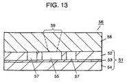
glass cover plate 58 havingsample injection inlet 59, a flow-in hole and a flow-out hole (both the holes are not shown), is attached on a first surface ofsubstrate 51. This completes polymerasechain reaction kit 56 of the embodiment. -
Injection inlet 59, the flow-in and flow-out holes are exactly alike to those introduced in the first embodiment in term of the manufacturing method, the positioning, and the shape. Like the structure in the first embodiment, forming the openings into a conical shape enhances an easy injection of a sample solution and a heating medium. In addition, disposing the holes to coverplate 58 is effective in that the sample solution can be easily set incavity 55 and the heating medium can be easily put into, and collected fromchannel 57. - Fig. 14 shows an exploded perspective view, which is cut at a section, of polymerase
chain reaction kit 68 of a third embodiment. Fig. 15 is a sectional view of the kit shown in Fig. 14. For sake of clarity, both the figures show the sections taken at sample injection inlet 66 (hereinafter, inlet 66).Cavity 62 is formed, as shown in Fig. 14, on a first surface ofsubstrate 61.Flow channel 63 is disposed on a second surface ofsubstrate 61 so as to run alongside section 169 ofcavity 62.Substrate 61 is sandwiched betweenfirst cover plate 64 havinginlet 66 andsecond cover plate 65 having a flow-in hole (not shown) and flow-outhole 67 for a heating medium. Serving as a barrier,side section 169 separatescavity 62 containing a sample solution fromchannel 63 through which a heating medium circulates. Therefore, the structure is free from the worry that the sample solution could mix with the heating medium. - In the structure of the first embodiment shown in Fig. 1,
cavity 2 and flowchannel 3 are divided by attachingcover plate 12 withbarrier 4. When a gaseous fluid, such as He, N2, is employed for a heating medium, such structured kit can cause a problem - ifflow channel 3 has a minor defect due to poor attachment, the gaseous fluid could escape through the clearance intocavity 2. On the other hand, the kit of the third embodiment provides a complete separation between the sample solution and the heating medium, accordingly, such inconveniencies will never occur. - Here will be described a still further structure of the embodiment. Fig. 16 shows an exploded perspective view, which is cut at a section, of polymerase
chain reaction kit 78 of the embodiment. Fig. 17 is a sectional view of the kit shown in Fig. 16. For sake of clarity, both the figures show the sections taken at sample injection inlet 76 (hereinafter, inlet 76). -
Cavity 72 is formed, as shown in Fig. 16, on a first surface ofsubstrate 71.Flow channel 73 is disposed on a second surface ofsubstrate 71 so as to run alongbottom section 179 ofcavity 72. Like the structure earlier described in the embodiment,substrate 71 is sandwiched betweenfirst cover plate 74 havinginlet 76 andsecond cover plate 75 having a flow-in hole (not shown) and flow-outhole 77 for a heating medium. Serving as a barrier,bottom section 179 completely separatescavity 72 containing a sample solution fromchannel 73 through which a heating medium circulates. The structure in which the flow channel runs beneath the cavity allowsflow channel 73 to have larger area to cover largely formedcavity 72. With such a structure, the heating medium circulating throughflow channel 73 can control, with reliability, the temperature of the sample solution incavity 2. The width offlow channel 73 should preferably be greater, as shown in Fig. 17, thanbottom section 179 ofcavity 72. Such a structure contributes to an effective heat exchange through the entire area ofbottom section 179, as well as helping an easy formation offlow channel 73. - Here will be described a yet further structure of the embodiment. Fig. 18 shows an exploded perspective view, which is cut at a section, of polymerase
chain reaction kit 88 of the embodiment. Fig. 19 is a sectional view of the kit shown in Fig. 18. For sake of clarity, both the figures show the sections taken at sample injection inlet 86 (hereinafter, inlet 86). -
Cavity 82 is formed, as shown in Fig. 18, on a first surface ofsubstrate 81.Flow channel 83 is disposed on a second surface ofsubstrate 81 so as to run alongbottom section 189A andside section 189B ofcavity 82. Like the structure earlier described in the embodiment,substrate 81 is sandwiched betweenfirst cover plate 84 havinginlet 86 andsecond cover plate 85 having a flow-in hole (not shown) and flow-outhole 87 for a heating medium. Like the aforementioned two structures,cavity 82 containing a sample solution and flowchannel 83 are completely separated by a barrier formed ofbottom section 189A andside section 189B. The structure, in which flowchannel 83 runs along the side and the bottom ofcavity 82, allowsflow channel 83 to surroundcavity 82 with larger area in the case ofcavity 82 with larger area. Such a structure further enhances heat exchange between a sample solution and a heating medium. - According to the structures in the embodiment, a sample solution undergoes the chain reaction in
cavities channels cavities barriers cavities - Next will be described the procedures of manufacturing polymerase
chain reaction kits - To begin with, the procedure of
manufacturing kit 68 of Fig. 14 will be described with reference to Figs. 20 through 22. -
Cavity 62 is formed, as shown in Fig. 20, on the first surface ofsilicon substrate 61. The forming process is the same as that described in the first embodiment; forming resistmask 69 by photolithography, and then formingcavity 62 through dry etching using a suppressing gas and a promotive gas for etching. - As the next step, resist
mask 70 is formed on the second surface ofsubstrate 61 by photolithography so as to run along both side sections ofcavity 62, and then flowchannel 63 is formed through dry etching. In the process, finishing the etching operation at an appropriate depth is needed so as not to etch throughsubstrate 61. - The following process is similarly done to that of the first embodiment. That is,
inlet 66 is formed in firstglass cover plate 64, on the other hand, the flow-in hole and flow-outhole 67 are formed in secondglass cover plate 65. The holes are formed by sand blasting. Attaching the two cover plates tosilicon substrate 61 completes polymerasechain reaction kit 68.Inlet 66, the flow-in hole, and flow-outhole 67 are exactly alike to those of the first embodiment in terms of the forming process, the shape, and the effect to be expected. - Now will be described the manufacturing process of
kit 78 shown in Fig. 16 with reference to Figs. 23 and 24. - Firstly, using photolithography, resist
mask 79 is formed on the first surface ofsubstrate 71, as shown in Fig. 23, and thencavity 72 is formed through dry etching. And flowchannel 73 is formed along the bottom ofcavity 72. After resistmask 80 is formed also by photolithography,flow channel 73 is formed through dry etching. In this process, great care should be taken not to etch through the bottom ofcavity 72. - Next, as is the case shown in Fig. 22,
first cover plate 74 havinginlet 76 andsecond cover plate 75 having a flow-in hole and flow-outhole 77 are attached so as tosandwich substrate 71 therebetween. This completes polymerasechain reaction kit 78. - Turning now to Figs. 25 and 26, the manufacturing process of
kit 88 will be described. - Firstly, using photolithography, resist
mask 89 is formed on the first surface ofsubstrate 81, as shown in Fig. 25, and thencavity 82 is formed through dry etching. And flowchannel 83 is formed along the side and bottom sections ofcavity 82. As the first step of forming the flow channel,flow channel 73 is formed along the bottom, as is the case shown in Fig. 23. Next, resistmask 90 is formed, as shown in Fig. 25, on the bottom ofcavity 82, and then the etching is performed along the side sections ofcavity 82. In this way, intendedflow channel 83 completes. - Fig. 26 shows the following process, that is, as is the case shown in Fig. 22,
first cover plate 84 havinginlet 86 andsecond cover plate 85 having a flow-in hole and flow-outhole 87 are attached so as tosandwich substrate 81 therebetween. This completes polymerasechain reaction kit 88. - As is described in the second embodiment,
substrates channels multi-layered substrate 91 employed for the kit shown in Fig. 16. Fig. 27 shows perspective view of the substrate as seen from the side ofcavity 95, while Fig. 28 shows perspective view of the substrate as seen from the side offlow channel 97. - As is apparent from Figs. 27 and 28,
flow channel 97 is separated fromcavity 95 bybarrier 96 alone that includes silicon dioxide. Such a structure allowscavity 95 andflow channel 97 to have an exact etching depth. Furthermore, asglass plate 93 sandwiched between outer layers separatescavity 95 fromflow channel 97,barrier 96 has a consistent thickness. - Compared to silicon, silicon dioxide has lower thermal conductivity. However, the silicon dioxide-containing
glass plate 93 can bear the thickness as small as 1 µm. Decreasing the thickness ofbarrier 96 to at most 10 µm thinner than the silicon barrier can overcome the lower thermal conductivity, which results in achieving high thermal efficiency. - Figs. 29 and 30 are sectional views illustrating the manufacturing process of the polymerase chain reaction
kit having substrate 91.Substrate 91 has, as shown in Fig. 29, a multi-layered structure formed of silicon layers 92 and 94, andglass plate 93 sandwiched therebetween. After the application of resistmasks substrate 91 by photolithography, the etching for the cavity and the flow channel is performed as is the case described in the first embodiment. The etching rate perceptibly slows down when the etching depth reaches the surface of silicon dioxide-containingglass plate 93. This contributes to the formation ofcavity 95 andflow channel 97 with each uniform depth. -
Barrier 96, namelyglass plate 93 of extremely thin, at most 10 µm, separatescavity 95 andflow channel 97. - Furthermore, attaching
first cover plate 100 andsecond cover plate 101 so as tosandwich substrate 91 completes the polymerase chain reaction kit as shown in Fig. 30. - Fig. 31 is a sectional view illustrating a polymerase chain reaction kit of a fourth embodiment. The inner wall of
cavity 108 is, as shown in Fig. 31, formed ofsilicon dioxide layer 109 alone, andbarrier 102 separating the interior ofcavity 108 fromflow channel 110 is also formed ofsilicon dioxide layer 109 alone. By virtue of such extremelythin barrier 102, a heating medium running throughflow channel 110 can rapidly and uniformly control the temperature of the sample solution contained incavity 108. - Here will be described the manufacturing process of the polymerase chain reaction kit of the embodiment with reference to the drawings.
- Figs. 32 through 35 are sectional views of the kit in the manufacturing process. Firstly, as shown in Fig. 32,
cavity 108 is formed insilicon substrate 105 through dry etching. The etching operation is the same as that described in other embodiments. - Next, as shown in Fig. 33, silicon dioxide-
layer 109 is formed, through thermal oxidization, on all over the surfaces ofsubstrate 105. The applied thickness of silicon dioxide-layer 109 finally becomes the thickness ofbarrier 102;substrate 105 undergoes the thermal oxidization untilbarrier 102 obtains a desired thickness. To serve asbarrier 102, the appliedlayer 109 is required to be pinhole-free. Forming the layer at least 2 µm can avoid such fatal defects. - Next, as shown in Fig. 34, resist
mask 111 is formed on a second ofsubstrate 105, and then silicon dioxide-layer 109 onsubstrate 105 is etched. Preferably, resistmask 111 should be applied onsubstrate 105 so as to have an exposed area greater than the bottom ofcavity 108. With the structure,flow channel 110 can be effectively formed along the side sections ofcavity 108. - Next, as shown in Fig. 35,
substrate 105 is etched at the second surface. The etching increases the depth towardcavity 108 and reaches the bottom ofcavity 108 first. The bottom, i.e.,barrier 102 is made of silicon dioxide-layer 109. Therefore,barrier 102 is resistant to the etching. Besides, patterning resistmask 111 in which an exposed area is formed greater than the bottom ofcavity 108 allowssubstrate 105 to be etched in the side sections ofcavity 108, with the result thatcavity 108 formed withsilicon dioxide barrier 102 remains. - Leaving a thickness of
silicon substrate 105 at the upper section ofcavity 108, as shown in Fig. 35, may be effective in reinforcing the structure. - As described earlier, the inner wall of
cavity 108 andbarrier 102 are made ofsilicon dioxide layer 109. Furthermore, the thermal oxidization method allowssilicon dioxide layer 109 to have a uniform thickness, and also to be extremely thin. With such a structure, a heating medium running throughflow channel 110 can control the temperature, with high efficiency, of the sample solution contained incavity 108. - Other than silicon oxide,
barrier 102 ofcavity 108 may be formed of silicon nitride, nickel, chrome, gold, and platinum, etc. When these materials are employed,barrier 102 is formed by commonly used thin-film deposition methods. That is, aftercavity 108 is formed, the inner wall ofbarrier 102 undergoes sputtering, vacuum evaporation, chemical vapor deposition (CVD), and plating, instead of the thermal oxidization for the silicon dioxide. In particular, gold and platinum have a thermal conductivity higher than silicon dioxide. Therefore, employing such metals allows the polymerase chain reaction kit to provide more rapid temperature control. - The kit of the embodiment has the structure in which flow
channel 110 andcavity 108 are separated by the barrier formed of a material whose etching rate is lower than that ofsubstrate 105. With such a structure,barrier 102 is free from being etched in the etching operation for formingcavity 108 andflow channel 110. Therefore, the cavity, the flow channel, and the barrier can be formed with high precision. - Fig. 36 is an exploded perspective view of the polymerase chain reaction kit of a fifth embodiment. Like the structure in the first embodiment,
substrate 115 hascavity 116 andflow channel 117 on its first surface. The structure differs from the one described in the first embodiment in that sample-injection inlets 121 (hereinafter, inlets 121), flow-inholes 120 and flow-outholes 119 for a heating medium are disposed on both sides ofsubstrate 115. That is, a portion ofcavity 116 reaches to the side ofsubstrate 115 and meetsinlet 121 there. Similarly,flow channel 117 reaches to the side ofsubstrate 115 and meets flow-inhole 120 and flow-outhole 119.Cavity 116 andflow channel 117 are sealed from the outside by covering the first surface ofsubstrate 115 withcover plate 122. Fluid communication with the outside is provided throughinlets 121, flow-inholes 120, and flow-outholes 119. Disposinginlets 121 on both sides of substrate 115 - one for injecting a sample solution, and the other for escaping the air from the cavity when the sample solution is injected-facilitates an easy injection. For a kit with a single injection inlet, the injection may be carried out with the help of a centrifugal. - In the aforementioned kit, a sample solution is injected, and a heating medium is set/collected through the holes disposed in the side surfaces of the substrate. That is, there is no need to form these holes in
cover plate 122. Such a structure not only allowssubstrate 115 to have the construction ofcavity 116 andflow channel 117 with higher density arrangement, but also allowscover plate 122 to be free from additional processes. -
Substrate 115 andcover plate 122 can be formed of materials the same as those of the first embodiment.Silicon substrate 115 paired withglass cover plate 122 is one of the excellent combinations. - Now will be described the procedure of manufacturing the polymerase chain reaction kit of the embodiment. Figs. 37 and 39 show sectional views and Figs. 38A and 38B show side views. The structure of the embodiment differs from the one described in the first embodiment in that
substrate 115 is covered with non-processed, i.e., no-hole cover plate 122. As shown in Fig. 37, resistmask 123 is applied on the first surface ofsubstrate 115, and thencavity 116 andflow channel 117 are formed. In the masking process, as shown in Figs. 38A and 38B, resistmask 123 is applied so thatinlet 121, flow-inhole 120, and flow-outhole 119 are formed on the side edge other ofsubstrate 115, and then the etching is performed. After that,cover plate 122 is set on the substrate, as shown in Fig. 39. - Through the processes above,
inlet 121, flow-inhole 120 and flow-outhole 119 are formed on the side ofsubstrate 115. To attachglass cover plate 122 withsilicon substrate 115, as is the case in the first embodiment, the direct attachment, the anodic attachment, and adhesives are employed. - Although the aforementioned description introduces the process in which
inlet 121, flow-inhole 120 and flow-outhole 119 are formed by etching, it is not limited thereto.Inlet 121, flow-inhole 120 and flow-outhole 119 may be formed, for example, by machining, after the formation ofcavity 116 andflow channel 117 completes. - Besides, when a plurality of the polymerase chain reaction kits is formed at a time,
substrate 115 is bonded to coverplate 122 in the form of a wafer, and then cut off at a predetermined position by dice cutting. The cutting allows individual kits to have flow-inhole 120 and flow-outhole 119 for a heating medium on the sides. - According to the embodiment described above,
inlet 121, flow-inhole 120 and flow-outhole 119 are formed on the side of the bonded structure ofsubstrate 115 andcover plate 122. Forming these holes on the side not only allowscover plate 122 to be free from additional processes, but also allowssubstrate 115 to have the construction of the cavity and the flow channel with higher density arrangement. Forming any one ofinlet 121, flow-inhole 120 and flow-outhole 119 on the side can contribute to a high-density construction of the cavity and the flow channel. - It will be understood that the manufacturing method described in the embodiment is applicable with the same advantages to the second, third, and fourth embodiments.
- The present invention provides a kit employed for polymerase chain reaction. The kit has a substrate in which a cavity and a flow channel are formed. The flow channel is separated from the cavity by at least a barrier formed along the cavity. Such a structure allows the cavity to be filled with a sample solution even in minute quantities. At the same time, the structure can provide a sample solution with a rapid temperature-control. The structure can therefore contribute to accelerated polymerase chain reaction.
Claims (31)
- A polymerase chain reaction kit comprising:a substrate on which a cavity, a flow channel for circulating a heating medium, and a barrier for separating the cavity and the flow channel are formed; andat least one cover plate of a plurality of cover plates for sealing at least one of the cavity and the flow channel.
- The polymerase chain reaction kit of Claim 1, wherein the substrate has the flow channel and the cavity on a same surface.
- The polymerase chain reaction kit of Claim 1, wherein the cavity is formed in a first surface of the substrate, whereas the flow channel is formed in a second surface opposite to the first surface of the substrate, the plurality of cover plates include a first cover plate for sealing the cavity, and a second cover plate for sealing the flow channel.
- The polymerase chain reaction kit of Claim 1, wherein the flow channel is formed on the substrate so as to run along at least a section of a side of the cavity.
- The polymerase chain reaction kit of Claim 3, wherein the flow channel is formed on the substrate so as to run along at least a section of a bottom of the cavity.
- The polymerase chain reaction kit of Claim 1, wherein at least a portion, which separates the cavity from the flow channel, of the barrier is formed of same material as that forming the substrate.
- The polymerase chain reaction kit of Claim 3, wherein at least a portion, which separates the cavity from the flow channel, of the barrier is formed of material having an etching rate smaller than that forming the substrate in an identical etching method.
- The polymerase chain reaction kit of Claim 1, wherein the substrate is made of silicon.
- The polymerase chain reaction kit of Claim 1, wherein the substrate is formed of any one of i) silicon, ii) silicon oxide, and iii) glass including silicon oxide, similarly, the cover plate is formed of any one of i) silicon, ii) silicon oxide, and iii) glass including silicon oxide.
- The polymerase chain reaction kit of Claim 1, wherein the substrate has a multi-layered structure formed of silicon layer and any one layer of i) silicon dioxide and ii) a glass substrate including silicon dioxide.
- The polymerase chain reaction kit of Claim 3, wherein material of at least a portion, which separates the cavity from the flow channel, of the barrier includes any one of i) silicon dioxide, ii) silicon nitride, iii) gold, iv) platinum, v) chrome, and vi) nickel.
- The polymerase chain reaction kit of Claim 1, wherein the cover plate contains any one of i) a sample-injection inlet connected to the cavity, ii) a flow-in hole connected to the flow channel, and iii) a flow-out hole connected to the flow channel.
- The polymerase chain reaction kit of Claim 3, wherein the first cover plate contains a sample-injection inlet connected to the cavity, while the second cover plate contains a flow-in hole and a flow-out hole connected to the flow channel.
- The polymerase chain reaction kit of Claim 12, wherein at least any one of i) the sample-injection inlet, ii) the flow-in hole, and iii) the flow-out hole, all of which are disposed in the cover plate, is formed into conic so as to become narrower on a side attached to the substrate.
- The polymerase chain reaction kit of Claim 1, wherein at least any one of i) a sample-injection inlet connected to the cavity, ii) a flow-in hole connected to the flow channel, and iii) a flow-out hole connected to the flow channel is disposed on a side section formed by bonding the substrate and the cover plate.
- The polymerase chain reaction kit of Claim 1, wherein the substrate and the cover plate are directly attached.
- The polymerase chain reaction kit of Claim 1, wherein the barrier has a thickness at most 100 µm.
- The polymerase chain reaction kit of Claim 1, wherein the cavity formed on the substrate is shaped into any one of oval and rectangular in a horizontal plane.
- The polymerase chain reaction kit of Claim 4, wherein the cavity formed on the substrate is shaped into any one of i) a meander structure with at least two bends, and ii) a spiral structure.
- The polymerase chain reaction kit of Claim 5, wherein the substrate contains the flow channel having a bottom area wider than that of the cavity
- A method of manufacturing a polymerase chain reaction kit comprising the steps of:a) forming a cavity and a flow channel for circulating a heating medium separated from the cavity on a surface of a substrate;b) attaching the substrate to at least one cover plate of a plurality of cover plates;c) connecting the cavity to a sample-injection inlet exposed to outside; andd) connecting the flow channel to a flow-in hole and a flow-out hole exposed to outside.
- The method of manufacturing a polymerase chain reaction kit of Claim 21, wherein the a) step employs at least a promotive gas and a suppressive gas for etching.
- The method of manufacturing a polymerase chain reaction kit of Claim 21, wherein the cavity and the flow channel are formed in a same surface of the substrate in the a) step.
- The method of manufacturing a polymerase chain reaction kit of Claim 21, wherein at least any one of the sample-injection inlet, the flow-in hole and the flow-out hole is formed in the cover plate.
- The method of manufacturing a polymerase chain reaction kit of Claim 21, wherein the a) step further includes the sub steps of:and the plurality of cover plates include a first cover plate for sealing the cavity and a second cover plate for sealing the flow channel.a-1) forming the cavity on a first surface of the substrate; anda-2) forming the flow channel on a second surface opposite to the first surface of the substrate,
- The method of manufacturing a polymerase chain reaction kit of Claim 25, wherein the sample-injection inlet is formed in the first cover plate, while the flow-in hole and the flow-out hole are formed in the second plate.
- The method of manufacturing a polymerase chain reaction kit of Claim 25 further includes a step of e) forming a layer, which is formed of a material having an etching rate smaller than that of a material forming the substrate, on a inner wall of the cavity.
- The method of manufacturing a polymerase chain reaction kit of Claim 27, wherein the substrate is made of silicon, the layer is made of silicon dioxide, and the layer is formed by any one of i) thermal oxidization, ii) chemical vapor deposition (CVD), and iii) sputtering.
- The method of manufacturing a polymerase chain reaction kit of Claim 27, wherein the substrate is made of silicon, the layer is made of any one of i) gold, ii) platinum, iii) chrome, iv) nickel, and the layer is formed by any one of i) CVD, ii) sputtering, iii) vacuum evaporation, and iv) plating.
- The method of manufacturing a polymerase chain reaction kit of Claim 21, wherein the b) step employs any one of direct attachment and anodic attachment.
- The method of manufacturing a polymerase chain reaction kit of Claim 24, wherein any one of the sample-injection inlet, the flow-in hole and the flow-out hole is formed, by sand blasting, in at least one of the c) step and d) step.
Applications Claiming Priority (3)
| Application Number | Priority Date | Filing Date | Title |
|---|---|---|---|
| JP2002197038A JP4013671B2 (en) | 2002-07-05 | 2002-07-05 | Polymerase chain reaction vessel and method for producing the same |
| JP2002197038 | 2002-07-05 | ||
| PCT/JP2003/008467 WO2004005507A1 (en) | 2002-07-05 | 2003-07-03 | Polymerase chain reaction container and process for producing the same |
Publications (3)
| Publication Number | Publication Date |
|---|---|
| EP1418233A1 true EP1418233A1 (en) | 2004-05-12 |
| EP1418233A4 EP1418233A4 (en) | 2005-09-14 |
| EP1418233B1 EP1418233B1 (en) | 2007-02-21 |
Family
ID=30112387
Family Applications (1)
| Application Number | Title | Priority Date | Filing Date |
|---|---|---|---|
| EP03741179A Expired - Lifetime EP1418233B1 (en) | 2002-07-05 | 2003-07-03 | Polymerase chain reaction container and process for producing the same |
Country Status (6)
| Country | Link |
|---|---|
| US (2) | US7384782B2 (en) |
| EP (1) | EP1418233B1 (en) |
| JP (1) | JP4013671B2 (en) |
| CN (1) | CN1309828C (en) |
| DE (1) | DE60311941T2 (en) |
| WO (1) | WO2004005507A1 (en) |
Cited By (7)
| Publication number | Priority date | Publication date | Assignee | Title |
|---|---|---|---|---|
| US8058054B2 (en) | 2006-06-30 | 2011-11-15 | Canon U.S. Life Sciences, Inc. | Systems and methods for real-time PCR |
| EP2821138A1 (en) * | 2013-07-05 | 2015-01-07 | Thinxxs Microtechnology Ag | Flow cell with integrated dry substance |
| US10466159B2 (en) | 2014-11-28 | 2019-11-05 | Chipcare Corporation | Multiplex bead array assay |
| US10724069B2 (en) | 2014-09-29 | 2020-07-28 | Chipcare Corporation | Methods and devices for cell detection |
| EP3653693A4 (en) * | 2017-07-10 | 2020-12-23 | Boe Technology Group Co. Ltd. | Substrate for use in medical testing, gene sequencing method thereof, and gene sequencing chip |
| US10946376B2 (en) | 2013-07-05 | 2021-03-16 | Thinxxs Microtechnology Ag | Carrier element for introducing a dry substance into a flow cell |
| EP3754340A4 (en) * | 2018-02-16 | 2021-11-17 | Kyocera Corporation | Flow path device and measurement apparatus |
Families Citing this family (21)
| Publication number | Priority date | Publication date | Assignee | Title |
|---|---|---|---|---|
| WO2006035497A1 (en) * | 2004-09-29 | 2006-04-06 | Mukunoki, Akio | Nucleic acid amplification reaction vessel and nucleic acid amplification reaction apparatus |
| JP4878200B2 (en) * | 2005-06-29 | 2012-02-15 | キヤノン株式会社 | Biochemical reaction cassette |
| CN100562702C (en) * | 2006-03-02 | 2009-11-25 | 奇鋐科技股份有限公司 | Method for manufacturing flat heat pipe |
| CN101952411B (en) * | 2007-12-24 | 2014-10-29 | 霍尼韦尔国际公司 | A reactor for the quantitative analysis of nucleic acids |
| JP2010081806A (en) * | 2008-09-29 | 2010-04-15 | Tecnisco Ltd | Slide structure with temperature adjustment passage |
| WO2010082279A1 (en) * | 2009-01-15 | 2010-07-22 | パナソニック株式会社 | Flow channel structure and method for manufacturing same |
| CN102791882A (en) | 2010-01-20 | 2012-11-21 | 霍尼韦尔国际公司 | Reactor for quantitative analysis of nucleic acids |
| JP2013027844A (en) * | 2011-07-29 | 2013-02-07 | Kyocera Crystal Device Corp | Microreactor |
| JP5735563B2 (en) * | 2013-03-04 | 2015-06-17 | 株式会社テクニスコ | Slide structure with temperature control flow path |
| WO2015138343A1 (en) | 2014-03-10 | 2015-09-17 | Click Diagnostics, Inc. | Cartridge-based thermocycler |
| CN114958990A (en) | 2014-12-31 | 2022-08-30 | 维斯比医学公司 | Method for detecting target nucleic acid using molecular diagnostic test device |
| WO2017185067A1 (en) | 2016-04-22 | 2017-10-26 | Click Diagnostics, Inc. | Printed circuit board heater for an amplification module |
| WO2017197040A1 (en) | 2016-05-11 | 2017-11-16 | Click Diagnostics, Inc. | Devices and methods for nucleic acid extraction |
| WO2018005710A1 (en) | 2016-06-29 | 2018-01-04 | Click Diagnostics, Inc. | Devices and methods for the detection of molecules using a flow cell |
| USD800331S1 (en) | 2016-06-29 | 2017-10-17 | Click Diagnostics, Inc. | Molecular diagnostic device |
| USD800913S1 (en) | 2016-06-30 | 2017-10-24 | Click Diagnostics, Inc. | Detection window for molecular diagnostic device |
| USD800914S1 (en) | 2016-06-30 | 2017-10-24 | Click Diagnostics, Inc. | Status indicator for molecular diagnostic device |
| KR20200079264A (en) | 2017-11-09 | 2020-07-02 | 비스비 메디컬, 인코포레이티드 | Portable molecular diagnostic device and method for target virus detection |
| US11352675B2 (en) | 2020-01-03 | 2022-06-07 | Visby Medical, Inc. | Devices and methods for antibiotic susceptability testing |
| USD1055307S1 (en) | 2021-08-13 | 2024-12-24 | Visby Medical, Inc. | Molecular diagnostic device |
| CN115364918B (en) * | 2022-09-05 | 2023-04-14 | 鲲鹏基因(北京)科技有限责任公司 | Polymerase chain reaction analyzer temperature control device based on metal solid-liquid conversion |
Citations (3)
| Publication number | Priority date | Publication date | Assignee | Title |
|---|---|---|---|---|
| US5455175A (en) * | 1990-06-04 | 1995-10-03 | University Of Utah Research Foundation | Rapid thermal cycling device |
| US5939312A (en) * | 1995-05-24 | 1999-08-17 | Biometra Biomedizinische Analytik Gmbh | Miniaturized multi-chamber thermocycler |
| DE10106008A1 (en) * | 2000-02-11 | 2001-09-06 | Agilent Technologies Inc | Microreactor for performing polymerase chain reactions, requires only very small sample and is made of material stable during temperature cycling |
Family Cites Families (12)
| Publication number | Priority date | Publication date | Assignee | Title |
|---|---|---|---|---|
| ZA862334B (en) | 1985-03-28 | 1987-11-25 | Cetus Corp | Process for amplifying,detecting and/or cloning nucleic acid sequences |
| US4683202A (en) * | 1985-03-28 | 1987-07-28 | Cetus Corporation | Process for amplifying nucleic acid sequences |
| EP0636413B1 (en) * | 1993-07-28 | 2001-11-14 | PE Corporation (NY) | Nucleic acid amplification reaction apparatus and method |
| US5725831A (en) * | 1994-03-14 | 1998-03-10 | Becton Dickinson And Company | Nucleic acid amplification apparatus |
| US6168948B1 (en) * | 1995-06-29 | 2001-01-02 | Affymetrix, Inc. | Miniaturized genetic analysis systems and methods |
| US6136212A (en) * | 1996-08-12 | 2000-10-24 | The Regents Of The University Of Michigan | Polymer-based micromachining for microfluidic devices |
| US6143496A (en) * | 1997-04-17 | 2000-11-07 | Cytonix Corporation | Method of sampling, amplifying and quantifying segment of nucleic acid, polymerase chain reaction assembly having nanoliter-sized sample chambers, and method of filling assembly |
| US6977145B2 (en) * | 1999-07-28 | 2005-12-20 | Serono Genetics Institute S.A. | Method for carrying out a biochemical protocol in continuous flow in a microreactor |
| JP3790919B2 (en) | 1999-11-26 | 2006-06-28 | オリンパス株式会社 | Trace liquid reactor |
| JP4442035B2 (en) * | 2001-01-11 | 2010-03-31 | 株式会社島津製作所 | Microchannel chip |
| JP2003083965A (en) | 2001-09-10 | 2003-03-19 | Adgene Co Ltd | Protein/nucleic acid analyzing chip |
| WO2003031972A1 (en) * | 2001-10-05 | 2003-04-17 | Bml, Inc. | Sensing board |
-
2002
- 2002-07-05 JP JP2002197038A patent/JP4013671B2/en not_active Expired - Lifetime
-
2003
- 2003-07-03 CN CNB03800738XA patent/CN1309828C/en not_active Expired - Lifetime
- 2003-07-03 US US10/485,342 patent/US7384782B2/en not_active Expired - Fee Related
- 2003-07-03 DE DE60311941T patent/DE60311941T2/en not_active Expired - Lifetime
- 2003-07-03 EP EP03741179A patent/EP1418233B1/en not_active Expired - Lifetime
- 2003-07-03 WO PCT/JP2003/008467 patent/WO2004005507A1/en active IP Right Grant
-
2008
- 2008-04-28 US US12/149,147 patent/US7790441B2/en not_active Expired - Fee Related
Patent Citations (3)
| Publication number | Priority date | Publication date | Assignee | Title |
|---|---|---|---|---|
| US5455175A (en) * | 1990-06-04 | 1995-10-03 | University Of Utah Research Foundation | Rapid thermal cycling device |
| US5939312A (en) * | 1995-05-24 | 1999-08-17 | Biometra Biomedizinische Analytik Gmbh | Miniaturized multi-chamber thermocycler |
| DE10106008A1 (en) * | 2000-02-11 | 2001-09-06 | Agilent Technologies Inc | Microreactor for performing polymerase chain reactions, requires only very small sample and is made of material stable during temperature cycling |
Non-Patent Citations (1)
| Title |
|---|
| See also references of WO2004005507A1 * |
Cited By (11)
| Publication number | Priority date | Publication date | Assignee | Title |
|---|---|---|---|---|
| US8058054B2 (en) | 2006-06-30 | 2011-11-15 | Canon U.S. Life Sciences, Inc. | Systems and methods for real-time PCR |
| US9283563B2 (en) | 2006-06-30 | 2016-03-15 | Canon U.S. Life Sciences, Inc. | Systems and methods for real-time PCR |
| EP2821138A1 (en) * | 2013-07-05 | 2015-01-07 | Thinxxs Microtechnology Ag | Flow cell with integrated dry substance |
| WO2015001070A1 (en) * | 2013-07-05 | 2015-01-08 | Thinxxs Microtechnology Ag | Flow cell with an integrated dry substance |
| US10232367B2 (en) | 2013-07-05 | 2019-03-19 | Thinxxs Microtechnology Ag | Flow cell with an integrated dry substance |
| US10946376B2 (en) | 2013-07-05 | 2021-03-16 | Thinxxs Microtechnology Ag | Carrier element for introducing a dry substance into a flow cell |
| US10724069B2 (en) | 2014-09-29 | 2020-07-28 | Chipcare Corporation | Methods and devices for cell detection |
| US10466159B2 (en) | 2014-11-28 | 2019-11-05 | Chipcare Corporation | Multiplex bead array assay |
| EP3653693A4 (en) * | 2017-07-10 | 2020-12-23 | Boe Technology Group Co. Ltd. | Substrate for use in medical testing, gene sequencing method thereof, and gene sequencing chip |
| US11198904B2 (en) | 2017-07-10 | 2021-12-14 | Beijing Boe Optoelectronics Technology Co., Ltd. | Substrate for medical test, gene sequencing method and gene sequencing chip |
| EP3754340A4 (en) * | 2018-02-16 | 2021-11-17 | Kyocera Corporation | Flow path device and measurement apparatus |
Also Published As
| Publication number | Publication date |
|---|---|
| EP1418233A4 (en) | 2005-09-14 |
| JP4013671B2 (en) | 2007-11-28 |
| DE60311941T2 (en) | 2007-09-06 |
| EP1418233B1 (en) | 2007-02-21 |
| DE60311941D1 (en) | 2007-04-05 |
| WO2004005507A1 (en) | 2004-01-15 |
| CN1537165A (en) | 2004-10-13 |
| CN1309828C (en) | 2007-04-11 |
| JP2004033141A (en) | 2004-02-05 |
| US20040175713A1 (en) | 2004-09-09 |
| US20080308529A1 (en) | 2008-12-18 |
| US7384782B2 (en) | 2008-06-10 |
| US7790441B2 (en) | 2010-09-07 |
Similar Documents
| Publication | Publication Date | Title |
|---|---|---|
| US7790441B2 (en) | Polymerase chain reaction kit and method of manufacturing the same | |
| JP6698786B2 (en) | Single-Structure Biochip and Manufacturing Method Providing Process from Sample Introduction to Results Output | |
| US6132580A (en) | Miniature reaction chamber and devices incorporating same | |
| US20210276009A1 (en) | Micro chamber plate | |
| US9316331B2 (en) | Multilevel microfluidic systems and methods | |
| AU2001269929B2 (en) | Methods and devices for enhancing bonded substrate yields and regulating temperature | |
| KR100758273B1 (en) | A plastic based microfabricated thermal device and a method for manufacturing the same, and a dna amplification chip and a method for manufacturing the same using the same | |
| US20020060156A1 (en) | Integrated microvolume device | |
| JPH11509094A (en) | Integrated nucleic acid diagnostic device | |
| Yu et al. | 3-D microarrays biochip for DNA amplification in polydimethylsiloxane (PDMS) elastomer | |
| JP4878200B2 (en) | Biochemical reaction cassette | |
| US8900852B2 (en) | Amplification reaction vessel, and method of manufacturing the same | |
| JP4351171B2 (en) | SAMPLE PROCESSING APPARATUS HAVING PROCESS CHAMBER WITH BYPASS SLOT AND METHOD FOR PROCESSING SAMPLE MATERIAL IN PROCESS CHAMBER | |
| JP2013208127A (en) | Microreaction vessel, and polymerase chain reaction method using the same | |
| JP2006029485A (en) | Microvalve and micro fluid device having the same | |
| US20060216725A1 (en) | Polymer chain reaction apparatus using marangoni convection and polymer chain reaction method using the same | |
| US7230315B2 (en) | Integrated chemical microreactor with large area channels and manufacturing process thereof | |
| US20070252224A1 (en) | Integrated Chemical Microreactor With Large Area Channels and Manufacturing Process Thereof | |
| Sabella et al. | Direct PCR analysis of biological samples in disposable plastic microreactors for biochip applications | |
| US20090074637A1 (en) | Optimized Modular Microfluidic Devices | |
| KR20060065456A (en) | Micro heater using plastic substrate and manufacturing method thereof | |
| JP2008032414A (en) | Microchip |
Legal Events
| Date | Code | Title | Description |
|---|---|---|---|
| PUAI | Public reference made under article 153(3) epc to a published international application that has entered the european phase |
Free format text: ORIGINAL CODE: 0009012 |
|
| 17P | Request for examination filed |
Effective date: 20040123 |
|
| AK | Designated contracting states |
Kind code of ref document: A1 Designated state(s): AT BE BG CH CY CZ DE DK EE ES FI FR GB GR HU IE IT LI LU MC NL PT RO SE SI SK TR |
|
| AX | Request for extension of the european patent |
Extension state: AL LT LV MK |
|
| A4 | Supplementary search report drawn up and despatched |
Effective date: 20050729 |
|
| DAX | Request for extension of the european patent (deleted) | ||
| RBV | Designated contracting states (corrected) |
Designated state(s): AT BE BG DE FR GB |
|
| GRAP | Despatch of communication of intention to grant a patent |
Free format text: ORIGINAL CODE: EPIDOSNIGR1 |
|
| RBV | Designated contracting states (corrected) |
Designated state(s): DE FR GB |
|
| GRAS | Grant fee paid |
Free format text: ORIGINAL CODE: EPIDOSNIGR3 |
|
| GRAA | (expected) grant |
Free format text: ORIGINAL CODE: 0009210 |
|
| AK | Designated contracting states |
Kind code of ref document: B1 Designated state(s): DE FR GB |
|
| REG | Reference to a national code |
Ref country code: GB Ref legal event code: FG4D |
|
| REF | Corresponds to: |
Ref document number: 60311941 Country of ref document: DE Date of ref document: 20070405 Kind code of ref document: P |
|
| ET | Fr: translation filed | ||
| PLBE | No opposition filed within time limit |
Free format text: ORIGINAL CODE: 0009261 |
|
| STAA | Information on the status of an ep patent application or granted ep patent |
Free format text: STATUS: NO OPPOSITION FILED WITHIN TIME LIMIT |
|
| 26N | No opposition filed |
Effective date: 20071122 |
|
| REG | Reference to a national code |
Ref country code: GB Ref legal event code: 746 Effective date: 20091221 |
|
| REG | Reference to a national code |
Ref country code: FR Ref legal event code: PLFP Year of fee payment: 14 |
|
| REG | Reference to a national code |
Ref country code: FR Ref legal event code: PLFP Year of fee payment: 15 |
|
| REG | Reference to a national code |
Ref country code: FR Ref legal event code: PLFP Year of fee payment: 16 |
|
| PGFP | Annual fee paid to national office [announced via postgrant information from national office to epo] |
Ref country code: FR Payment date: 20210513 Year of fee payment: 19 |
|
| PGFP | Annual fee paid to national office [announced via postgrant information from national office to epo] |
Ref country code: GB Payment date: 20210609 Year of fee payment: 19 |
|
| PGFP | Annual fee paid to national office [announced via postgrant information from national office to epo] |
Ref country code: DE Payment date: 20210608 Year of fee payment: 19 |
|
| REG | Reference to a national code |
Ref country code: DE Ref legal event code: R119 Ref document number: 60311941 Country of ref document: DE |
|
| GBPC | Gb: european patent ceased through non-payment of renewal fee |
Effective date: 20220703 |
|
| PG25 | Lapsed in a contracting state [announced via postgrant information from national office to epo] |
Ref country code: FR Free format text: LAPSE BECAUSE OF NON-PAYMENT OF DUE FEES Effective date: 20220731 |
|
| PG25 | Lapsed in a contracting state [announced via postgrant information from national office to epo] |
Ref country code: GB Free format text: LAPSE BECAUSE OF NON-PAYMENT OF DUE FEES Effective date: 20220703 Ref country code: DE Free format text: LAPSE BECAUSE OF NON-PAYMENT OF DUE FEES Effective date: 20230201 |