EP1418233A1 - Behälter für die polymerasekettenreaktion und verfahren zu dessen herstellung - Google Patents
Behälter für die polymerasekettenreaktion und verfahren zu dessen herstellung Download PDFInfo
- Publication number
- EP1418233A1 EP1418233A1 EP03741179A EP03741179A EP1418233A1 EP 1418233 A1 EP1418233 A1 EP 1418233A1 EP 03741179 A EP03741179 A EP 03741179A EP 03741179 A EP03741179 A EP 03741179A EP 1418233 A1 EP1418233 A1 EP 1418233A1
- Authority
- EP
- European Patent Office
- Prior art keywords
- cavity
- chain reaction
- polymerase chain
- substrate
- reaction kit
- Prior art date
- Legal status (The legal status is an assumption and is not a legal conclusion. Google has not performed a legal analysis and makes no representation as to the accuracy of the status listed.)
- Granted
Links
Images


Classifications
-
- C—CHEMISTRY; METALLURGY
- C07—ORGANIC CHEMISTRY
- C07H—SUGARS; DERIVATIVES THEREOF; NUCLEOSIDES; NUCLEOTIDES; NUCLEIC ACIDS
- C07H21/00—Compounds containing two or more mononucleotide units having separate phosphate or polyphosphate groups linked by saccharide radicals of nucleoside groups, e.g. nucleic acids
-
- B—PERFORMING OPERATIONS; TRANSPORTING
- B01—PHYSICAL OR CHEMICAL PROCESSES OR APPARATUS IN GENERAL
- B01L—CHEMICAL OR PHYSICAL LABORATORY APPARATUS FOR GENERAL USE
- B01L3/00—Containers or dishes for laboratory use, e.g. laboratory glassware; Droppers
- B01L3/50—Containers for the purpose of retaining a material to be analysed, e.g. test tubes
- B01L3/502—Containers for the purpose of retaining a material to be analysed, e.g. test tubes with fluid transport, e.g. in multi-compartment structures
- B01L3/5027—Containers for the purpose of retaining a material to be analysed, e.g. test tubes with fluid transport, e.g. in multi-compartment structures by integrated microfluidic structures, i.e. dimensions of channels and chambers are such that surface tension forces are important, e.g. lab-on-a-chip
- B01L3/502707—Containers for the purpose of retaining a material to be analysed, e.g. test tubes with fluid transport, e.g. in multi-compartment structures by integrated microfluidic structures, i.e. dimensions of channels and chambers are such that surface tension forces are important, e.g. lab-on-a-chip characterised by the manufacture of the container or its components
-
- B—PERFORMING OPERATIONS; TRANSPORTING
- B01—PHYSICAL OR CHEMICAL PROCESSES OR APPARATUS IN GENERAL
- B01L—CHEMICAL OR PHYSICAL LABORATORY APPARATUS FOR GENERAL USE
- B01L2300/00—Additional constructional details
- B01L2300/08—Geometry, shape and general structure
- B01L2300/0809—Geometry, shape and general structure rectangular shaped
- B01L2300/0816—Cards, e.g. flat sample carriers usually with flow in two horizontal directions
-
- B—PERFORMING OPERATIONS; TRANSPORTING
- B01—PHYSICAL OR CHEMICAL PROCESSES OR APPARATUS IN GENERAL
- B01L—CHEMICAL OR PHYSICAL LABORATORY APPARATUS FOR GENERAL USE
- B01L2300/00—Additional constructional details
- B01L2300/08—Geometry, shape and general structure
- B01L2300/0861—Configuration of multiple channels and/or chambers in a single devices
- B01L2300/0877—Flow chambers
-
- B—PERFORMING OPERATIONS; TRANSPORTING
- B01—PHYSICAL OR CHEMICAL PROCESSES OR APPARATUS IN GENERAL
- B01L—CHEMICAL OR PHYSICAL LABORATORY APPARATUS FOR GENERAL USE
- B01L2300/00—Additional constructional details
- B01L2300/08—Geometry, shape and general structure
- B01L2300/0887—Laminated structure
-
- B—PERFORMING OPERATIONS; TRANSPORTING
- B01—PHYSICAL OR CHEMICAL PROCESSES OR APPARATUS IN GENERAL
- B01L—CHEMICAL OR PHYSICAL LABORATORY APPARATUS FOR GENERAL USE
- B01L2300/00—Additional constructional details
- B01L2300/18—Means for temperature control
- B01L2300/1838—Means for temperature control using fluid heat transfer medium
- B01L2300/185—Means for temperature control using fluid heat transfer medium using a liquid as fluid
-
- B—PERFORMING OPERATIONS; TRANSPORTING
- B01—PHYSICAL OR CHEMICAL PROCESSES OR APPARATUS IN GENERAL
- B01L—CHEMICAL OR PHYSICAL LABORATORY APPARATUS FOR GENERAL USE
- B01L7/00—Heating or cooling apparatus; Heat insulating devices
- B01L7/52—Heating or cooling apparatus; Heat insulating devices with provision for submitting samples to a predetermined sequence of different temperatures, e.g. for treating nucleic acid samples
Definitions
- the rectangular shape of cavity 2 allows the structure to have a high-density arrangement in which a plurality of cavities 2 are located adjacent to each flow channel 3.
- the kit of the present embodiment can handle more than one sample solution for the polymerase chain reaction at a time.
- each cavity 2 may be filled with a sample solution containing different target DNA for amplifying more than one different target DNA.
- Providing each sample solution with temperature control by circulation of a heating medium allows the kit to separately carry out the polymerase chain reaction with respect to each sample solution.
- oval-shaped cavity 2 is also able to offer the same effect.
- fluoric acid bonding can be employed.
- the bonding the application of fluoric acid to the attached surfaces of substrate 1 and cover plate 12 melts the boundary area, providing a secure bond.
- the material combination commonly made of glass, or silica glass is employed.
- the material may be made of plastics. As described above, there are various material combinations; an optimal combination should be determined according to the following points: a bonding method, a processing method of cavity 2 and channel 3, required cavity-density, thermal conductivity of material, and costs.
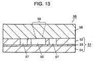
- resist mask 60 is formed on the side of upper silicon layer 52 of substrate 51 by photolithography. Cavity 55 and flow channel 57 are formed, as shown in Fig. 12, through dry etching. The dry etching is carried out in the same manner as that described in the first embodiment. The etching rate perceptibly slows down when the etching depth reaches the surface of glass plate 53. That is, the thickness of upper silicon layer 52 defines the depth of a cavity, allowing each cavity to have a uniform depth.
- Injection inlet 59 the flow-in and flow-out holes are exactly alike to those introduced in the first embodiment in term of the manufacturing method, the positioning, and the shape.
- forming the openings into a conical shape enhances an easy injection of a sample solution and a heating medium.
- disposing the holes to cover plate 58 is effective in that the sample solution can be easily set in cavity 55 and the heating medium can be easily put into, and collected from channel 57.
- cavity 2 and flow channel 3 are divided by attaching cover plate 12 with barrier 4.
- a gaseous fluid such as He, N 2
- the kit of the third embodiment provides a complete separation between the sample solution and the heating medium, accordingly, such inconveniencies will never occur.
- Cavity 62 is formed, as shown in Fig. 20, on the first surface of silicon substrate 61.
- the forming process is the same as that described in the first embodiment; forming resist mask 69 by photolithography, and then forming cavity 62 through dry etching using a suppressing gas and a promotive gas for etching.
- inlet 66 is formed in first glass cover plate 64
- the flow-in hole and flow-out hole 67 are formed in second glass cover plate 65.
- the holes are formed by sand blasting. Attaching the two cover plates to silicon substrate 61 completes polymerase chain reaction kit 68.
- Inlet 66, the flow-in hole, and flow-out hole 67 are exactly alike to those of the first embodiment in terms of the forming process, the shape, and the effect to be expected.
- kit 78 shown in Fig. 16 with reference to Figs. 23 and 24.
- kit 88 the manufacturing process of kit 88 will be described.
- resist mask 89 is formed on the first surface of substrate 81, as shown in Fig. 25, and then cavity 82 is formed through dry etching. And flow channel 83 is formed along the side and bottom sections of cavity 82.
- flow channel 73 is formed along the bottom, as is the case shown in Fig. 23.
- resist mask 90 is formed, as shown in Fig. 25, on the bottom of cavity 82, and then the etching is performed along the side sections of cavity 82. In this way, intended flow channel 83 completes.
- Fig. 26 shows the following process, that is, as is the case shown in Fig. 22, first cover plate 84 having inlet 86 and second cover plate 85 having a flow-in hole and flow-out hole 87 are attached so as to sandwich substrate 81 therebetween. This completes polymerase chain reaction kit 88.
- substrates 61, 71, and 81 should preferably be formed of a multi-layered structure made of silicon layers, and silicon dioxide or a glass plate including silicon dioxide.
- the multi-layered substrate is especially effective in the structure of the embodiment in which flow channels 63, 73, and 83 run beneath the cavity.
- Figs. 27 and 28 are perspective views illustrating multi-layered substrate 91 employed for the kit shown in Fig. 16.
- Fig. 27 shows perspective view of the substrate as seen from the side of cavity 95
- Fig. 28 shows perspective view of the substrate as seen from the side of flow channel 97.
- flow channel 97 is separated from cavity 95 by barrier 96 alone that includes silicon dioxide.
- barrier 96 alone that includes silicon dioxide.
- Such a structure allows cavity 95 and flow channel 97 to have an exact etching depth.
- glass plate 93 sandwiched between outer layers separates cavity 95 from flow channel 97, barrier 96 has a consistent thickness.
- Fig. 31 is a sectional view illustrating a polymerase chain reaction kit of a fourth embodiment.
- the inner wall of cavity 108 is, as shown in Fig. 31, formed of silicon dioxide layer 109 alone, and barrier 102 separating the interior of cavity 108 from flow channel 110 is also formed of silicon dioxide layer 109 alone.
- barrier 102 By virtue of such extremely thin barrier 102, a heating medium running through flow channel 110 can rapidly and uniformly control the temperature of the sample solution contained in cavity 108.
- Figs. 32 through 35 are sectional views of the kit in the manufacturing process. Firstly, as shown in Fig. 32, cavity 108 is formed in silicon substrate 105 through dry etching. The etching operation is the same as that described in other embodiments.
- silicon dioxide-layer 109 is formed, through thermal oxidization, on all over the surfaces of substrate 105.
- the applied thickness of silicon dioxide-layer 109 finally becomes the thickness of barrier 102; substrate 105 undergoes the thermal oxidization until barrier 102 obtains a desired thickness.
- the applied layer 109 is required to be pinhole-free. Forming the layer at least 2 ⁇ m can avoid such fatal defects.
- resist mask 111 is formed on a second of substrate 105, and then silicon dioxide-layer 109 on substrate 105 is etched.
- resist mask 111 should be applied on substrate 105 so as to have an exposed area greater than the bottom of cavity 108. With the structure, flow channel 110 can be effectively formed along the side sections of cavity 108.
- the inner wall of cavity 108 and barrier 102 are made of silicon dioxide layer 109. Furthermore, the thermal oxidization method allows silicon dioxide layer 109 to have a uniform thickness, and also to be extremely thin. With such a structure, a heating medium running through flow channel 110 can control the temperature, with high efficiency, of the sample solution contained in cavity 108.
- barrier 102 of cavity 108 may be formed of silicon nitride, nickel, chrome, gold, and platinum, etc. When these materials are employed, barrier 102 is formed by commonly used thin-film deposition methods. That is, after cavity 108 is formed, the inner wall of barrier 102 undergoes sputtering, vacuum evaporation, chemical vapor deposition (CVD), and plating, instead of the thermal oxidization for the silicon dioxide. In particular, gold and platinum have a thermal conductivity higher than silicon dioxide. Therefore, employing such metals allows the polymerase chain reaction kit to provide more rapid temperature control.
- the kit of the embodiment has the structure in which flow channel 110 and cavity 108 are separated by the barrier formed of a material whose etching rate is lower than that of substrate 105.
- barrier 102 is free from being etched in the etching operation for forming cavity 108 and flow channel 110. Therefore, the cavity, the flow channel, and the barrier can be formed with high precision.
- Fig. 36 is an exploded perspective view of the polymerase chain reaction kit of a fifth embodiment.
- substrate 115 has cavity 116 and flow channel 117 on its first surface.
- the structure differs from the one described in the first embodiment in that sample-injection inlets 121 (hereinafter, inlets 121), flow-in holes 120 and flow-out holes 119 for a heating medium are disposed on both sides of substrate 115. That is, a portion of cavity 116 reaches to the side of substrate 115 and meets inlet 121 there. Similarly, flow channel 117 reaches to the side of substrate 115 and meets flow-in hole 120 and flow-out hole 119.
- Cavity 116 and flow channel 117 are sealed from the outside by covering the first surface of substrate 115 with cover plate 122. Fluid communication with the outside is provided through inlets 121, flow-in holes 120, and flow-out holes 119. Disposing inlets 121 on both sides of substrate 115 - one for injecting a sample solution, and the other for escaping the air from the cavity when the sample solution is injected-facilitates an easy injection. For a kit with a single injection inlet, the injection may be carried out with the help of a centrifugal.
- a sample solution is injected, and a heating medium is set/collected through the holes disposed in the side surfaces of the substrate. That is, there is no need to form these holes in cover plate 122.
- a heating medium is set/collected through the holes disposed in the side surfaces of the substrate. That is, there is no need to form these holes in cover plate 122.
- Substrate 115 and cover plate 122 can be formed of materials the same as those of the first embodiment. Silicon substrate 115 paired with glass cover plate 122 is one of the excellent combinations.
- Figs. 37 and 39 show sectional views and Figs. 38A and 38B show side views.
- the structure of the embodiment differs from the one described in the first embodiment in that substrate 115 is covered with non-processed, i.e., no-hole cover plate 122.
- resist mask 123 is applied on the first surface of substrate 115, and then cavity 116 and flow channel 117 are formed.
- resist mask 123 is applied so that inlet 121, flow-in hole 120, and flow-out hole 119 are formed on the side edge other of substrate 115, and then the etching is performed.
- cover plate 122 is set on the substrate, as shown in Fig. 39.
- inlet 121, flow-in hole 120 and flow-out hole 119 are formed on the side of substrate 115.
- the direct attachment, the anodic attachment, and adhesives are employed.
- inlet 121, flow-in hole 120 and flow-out hole 119 are formed by etching, it is not limited thereto.
- Inlet 121, flow-in hole 120 and flow-out hole 119 may be formed, for example, by machining, after the formation of cavity 116 and flow channel 117 completes.
- substrate 115 is bonded to cover plate 122 in the form of a wafer, and then cut off at a predetermined position by dice cutting.
- the cutting allows individual kits to have flow-in hole 120 and flow-out hole 119 for a heating medium on the sides.
- inlet 121, flow-in hole 120 and flow-out hole 119 are formed on the side of the bonded structure of substrate 115 and cover plate 122. Forming these holes on the side not only allows cover plate 122 to be free from additional processes, but also allows substrate 115 to have the construction of the cavity and the flow channel with higher density arrangement. Forming any one of inlet 121, flow-in hole 120 and flow-out hole 119 on the side can contribute to a high-density construction of the cavity and the flow channel.
- the present invention provides a kit employed for polymerase chain reaction.
- the kit has a substrate in which a cavity and a flow channel are formed.
- the flow channel is separated from the cavity by at least a barrier formed along the cavity.
- Such a structure allows the cavity to be filled with a sample solution even in minute quantities.
- the structure can provide a sample solution with a rapid temperature-control. The structure can therefore contribute to accelerated polymerase chain reaction.
Landscapes
- Chemical & Material Sciences (AREA)
- Health & Medical Sciences (AREA)
- General Health & Medical Sciences (AREA)
- Life Sciences & Earth Sciences (AREA)
- Biochemistry (AREA)
- Molecular Biology (AREA)
- Organic Chemistry (AREA)
- Genetics & Genomics (AREA)
- Biotechnology (AREA)
- Engineering & Computer Science (AREA)
- Dispersion Chemistry (AREA)
- Analytical Chemistry (AREA)
- Hematology (AREA)
- Clinical Laboratory Science (AREA)
- Chemical Kinetics & Catalysis (AREA)
- Apparatus Associated With Microorganisms And Enzymes (AREA)
- Measuring Or Testing Involving Enzymes Or Micro-Organisms (AREA)
Applications Claiming Priority (3)
| Application Number | Priority Date | Filing Date | Title |
|---|---|---|---|
| JP2002197038A JP4013671B2 (ja) | 2002-07-05 | 2002-07-05 | ポリメラーゼ連鎖反応容器及びその製造方法 |
| JP2002197038 | 2002-07-05 | ||
| PCT/JP2003/008467 WO2004005507A1 (ja) | 2002-07-05 | 2003-07-03 | ポリメラーゼ連鎖反応容器及びその製造方法 |
Publications (3)
| Publication Number | Publication Date |
|---|---|
| EP1418233A1 true EP1418233A1 (de) | 2004-05-12 |
| EP1418233A4 EP1418233A4 (de) | 2005-09-14 |
| EP1418233B1 EP1418233B1 (de) | 2007-02-21 |
Family
ID=30112387
Family Applications (1)
| Application Number | Title | Priority Date | Filing Date |
|---|---|---|---|
| EP03741179A Expired - Lifetime EP1418233B1 (de) | 2002-07-05 | 2003-07-03 | Behälter für die polymerasekettenreaktion und verfahren zu dessen herstellung |
Country Status (6)
| Country | Link |
|---|---|
| US (2) | US7384782B2 (de) |
| EP (1) | EP1418233B1 (de) |
| JP (1) | JP4013671B2 (de) |
| CN (1) | CN1309828C (de) |
| DE (1) | DE60311941T2 (de) |
| WO (1) | WO2004005507A1 (de) |
Cited By (7)
| Publication number | Priority date | Publication date | Assignee | Title |
|---|---|---|---|---|
| US8058054B2 (en) | 2006-06-30 | 2011-11-15 | Canon U.S. Life Sciences, Inc. | Systems and methods for real-time PCR |
| EP2821138A1 (de) * | 2013-07-05 | 2015-01-07 | Thinxxs Microtechnology Ag | Flusszelle mit integrierter Trockensubstanz |
| US10466159B2 (en) | 2014-11-28 | 2019-11-05 | Chipcare Corporation | Multiplex bead array assay |
| US10724069B2 (en) | 2014-09-29 | 2020-07-28 | Chipcare Corporation | Methods and devices for cell detection |
| EP3653693A4 (de) * | 2017-07-10 | 2020-12-23 | Boe Technology Group Co. Ltd. | Substrat zur verwendung in medizinischen tests, gensequenzierungsverfahren dafür und gensequenzierungschip |
| US10946376B2 (en) | 2013-07-05 | 2021-03-16 | Thinxxs Microtechnology Ag | Carrier element for introducing a dry substance into a flow cell |
| EP3754340A4 (de) * | 2018-02-16 | 2021-11-17 | Kyocera Corporation | Strömungswegvorrichtung und messvorrichtung |
Families Citing this family (21)
| Publication number | Priority date | Publication date | Assignee | Title |
|---|---|---|---|---|
| WO2006035497A1 (ja) * | 2004-09-29 | 2006-04-06 | Mukunoki, Akio | 核酸増幅反応容器及び核酸増幅反応装置 |
| JP4878200B2 (ja) * | 2005-06-29 | 2012-02-15 | キヤノン株式会社 | 生化学反応カセット |
| CN100562702C (zh) * | 2006-03-02 | 2009-11-25 | 奇鋐科技股份有限公司 | 平板式热管的制造方法 |
| CN101952411B (zh) * | 2007-12-24 | 2014-10-29 | 霍尼韦尔国际公司 | 用于核酸定量分析的反应器 |
| JP2010081806A (ja) * | 2008-09-29 | 2010-04-15 | Tecnisco Ltd | 温度調節流路付きスライド構造 |
| WO2010082279A1 (ja) * | 2009-01-15 | 2010-07-22 | パナソニック株式会社 | 流路構造体およびその製造方法 |
| CN102791882A (zh) | 2010-01-20 | 2012-11-21 | 霍尼韦尔国际公司 | 用于核酸定量分析的反应器 |
| JP2013027844A (ja) * | 2011-07-29 | 2013-02-07 | Kyocera Crystal Device Corp | マイクロリアクター |
| JP5735563B2 (ja) * | 2013-03-04 | 2015-06-17 | 株式会社テクニスコ | 温度調節流路付きスライド構造 |
| WO2015138343A1 (en) | 2014-03-10 | 2015-09-17 | Click Diagnostics, Inc. | Cartridge-based thermocycler |
| CN114958990A (zh) | 2014-12-31 | 2022-08-30 | 维斯比医学公司 | 使用分子诊断测试装置检测靶核酸的方法 |
| WO2017185067A1 (en) | 2016-04-22 | 2017-10-26 | Click Diagnostics, Inc. | Printed circuit board heater for an amplification module |
| WO2017197040A1 (en) | 2016-05-11 | 2017-11-16 | Click Diagnostics, Inc. | Devices and methods for nucleic acid extraction |
| WO2018005710A1 (en) | 2016-06-29 | 2018-01-04 | Click Diagnostics, Inc. | Devices and methods for the detection of molecules using a flow cell |
| USD800331S1 (en) | 2016-06-29 | 2017-10-17 | Click Diagnostics, Inc. | Molecular diagnostic device |
| USD800913S1 (en) | 2016-06-30 | 2017-10-24 | Click Diagnostics, Inc. | Detection window for molecular diagnostic device |
| USD800914S1 (en) | 2016-06-30 | 2017-10-24 | Click Diagnostics, Inc. | Status indicator for molecular diagnostic device |
| KR20200079264A (ko) | 2017-11-09 | 2020-07-02 | 비스비 메디컬, 인코포레이티드 | 표적 바이러스 검출을 위한 휴대용 분자 진단 디바이스 및 방법 |
| US11352675B2 (en) | 2020-01-03 | 2022-06-07 | Visby Medical, Inc. | Devices and methods for antibiotic susceptability testing |
| USD1055307S1 (en) | 2021-08-13 | 2024-12-24 | Visby Medical, Inc. | Molecular diagnostic device |
| CN115364918B (zh) * | 2022-09-05 | 2023-04-14 | 鲲鹏基因(北京)科技有限责任公司 | 基于金属固液转化的聚合酶链式反应分析仪温控装置 |
Citations (3)
| Publication number | Priority date | Publication date | Assignee | Title |
|---|---|---|---|---|
| US5455175A (en) * | 1990-06-04 | 1995-10-03 | University Of Utah Research Foundation | Rapid thermal cycling device |
| US5939312A (en) * | 1995-05-24 | 1999-08-17 | Biometra Biomedizinische Analytik Gmbh | Miniaturized multi-chamber thermocycler |
| DE10106008A1 (de) * | 2000-02-11 | 2001-09-06 | Agilent Technologies Inc | PCR-Mikroreaktor zum Vermehren von DNA unter Verwendung von Mikromengen eines Probenfluids |
Family Cites Families (12)
| Publication number | Priority date | Publication date | Assignee | Title |
|---|---|---|---|---|
| ZA862334B (en) | 1985-03-28 | 1987-11-25 | Cetus Corp | Process for amplifying,detecting and/or cloning nucleic acid sequences |
| US4683202A (en) * | 1985-03-28 | 1987-07-28 | Cetus Corporation | Process for amplifying nucleic acid sequences |
| EP0636413B1 (de) * | 1993-07-28 | 2001-11-14 | PE Corporation (NY) | Vorrichtung und Verfahren zur Nukleinsäurevervielfältigung |
| US5725831A (en) * | 1994-03-14 | 1998-03-10 | Becton Dickinson And Company | Nucleic acid amplification apparatus |
| US6168948B1 (en) * | 1995-06-29 | 2001-01-02 | Affymetrix, Inc. | Miniaturized genetic analysis systems and methods |
| US6136212A (en) * | 1996-08-12 | 2000-10-24 | The Regents Of The University Of Michigan | Polymer-based micromachining for microfluidic devices |
| US6143496A (en) * | 1997-04-17 | 2000-11-07 | Cytonix Corporation | Method of sampling, amplifying and quantifying segment of nucleic acid, polymerase chain reaction assembly having nanoliter-sized sample chambers, and method of filling assembly |
| US6977145B2 (en) * | 1999-07-28 | 2005-12-20 | Serono Genetics Institute S.A. | Method for carrying out a biochemical protocol in continuous flow in a microreactor |
| JP3790919B2 (ja) | 1999-11-26 | 2006-06-28 | オリンパス株式会社 | 微量液体の反応装置 |
| JP4442035B2 (ja) * | 2001-01-11 | 2010-03-31 | 株式会社島津製作所 | マイクロチャンネル型チップ |
| JP2003083965A (ja) | 2001-09-10 | 2003-03-19 | Adgene Co Ltd | 蛋白・核酸解析用チップ |
| WO2003031972A1 (fr) * | 2001-10-05 | 2003-04-17 | Bml, Inc. | Plaque de detection |
-
2002
- 2002-07-05 JP JP2002197038A patent/JP4013671B2/ja not_active Expired - Lifetime
-
2003
- 2003-07-03 CN CNB03800738XA patent/CN1309828C/zh not_active Expired - Lifetime
- 2003-07-03 US US10/485,342 patent/US7384782B2/en not_active Expired - Fee Related
- 2003-07-03 DE DE60311941T patent/DE60311941T2/de not_active Expired - Lifetime
- 2003-07-03 EP EP03741179A patent/EP1418233B1/de not_active Expired - Lifetime
- 2003-07-03 WO PCT/JP2003/008467 patent/WO2004005507A1/ja active IP Right Grant
-
2008
- 2008-04-28 US US12/149,147 patent/US7790441B2/en not_active Expired - Fee Related
Patent Citations (3)
| Publication number | Priority date | Publication date | Assignee | Title |
|---|---|---|---|---|
| US5455175A (en) * | 1990-06-04 | 1995-10-03 | University Of Utah Research Foundation | Rapid thermal cycling device |
| US5939312A (en) * | 1995-05-24 | 1999-08-17 | Biometra Biomedizinische Analytik Gmbh | Miniaturized multi-chamber thermocycler |
| DE10106008A1 (de) * | 2000-02-11 | 2001-09-06 | Agilent Technologies Inc | PCR-Mikroreaktor zum Vermehren von DNA unter Verwendung von Mikromengen eines Probenfluids |
Non-Patent Citations (1)
| Title |
|---|
| See also references of WO2004005507A1 * |
Cited By (11)
| Publication number | Priority date | Publication date | Assignee | Title |
|---|---|---|---|---|
| US8058054B2 (en) | 2006-06-30 | 2011-11-15 | Canon U.S. Life Sciences, Inc. | Systems and methods for real-time PCR |
| US9283563B2 (en) | 2006-06-30 | 2016-03-15 | Canon U.S. Life Sciences, Inc. | Systems and methods for real-time PCR |
| EP2821138A1 (de) * | 2013-07-05 | 2015-01-07 | Thinxxs Microtechnology Ag | Flusszelle mit integrierter Trockensubstanz |
| WO2015001070A1 (de) * | 2013-07-05 | 2015-01-08 | Thinxxs Microtechnology Ag | Flusszelle mit integrierter trockensubstanz |
| US10232367B2 (en) | 2013-07-05 | 2019-03-19 | Thinxxs Microtechnology Ag | Flow cell with an integrated dry substance |
| US10946376B2 (en) | 2013-07-05 | 2021-03-16 | Thinxxs Microtechnology Ag | Carrier element for introducing a dry substance into a flow cell |
| US10724069B2 (en) | 2014-09-29 | 2020-07-28 | Chipcare Corporation | Methods and devices for cell detection |
| US10466159B2 (en) | 2014-11-28 | 2019-11-05 | Chipcare Corporation | Multiplex bead array assay |
| EP3653693A4 (de) * | 2017-07-10 | 2020-12-23 | Boe Technology Group Co. Ltd. | Substrat zur verwendung in medizinischen tests, gensequenzierungsverfahren dafür und gensequenzierungschip |
| US11198904B2 (en) | 2017-07-10 | 2021-12-14 | Beijing Boe Optoelectronics Technology Co., Ltd. | Substrate for medical test, gene sequencing method and gene sequencing chip |
| EP3754340A4 (de) * | 2018-02-16 | 2021-11-17 | Kyocera Corporation | Strömungswegvorrichtung und messvorrichtung |
Also Published As
| Publication number | Publication date |
|---|---|
| EP1418233A4 (de) | 2005-09-14 |
| JP4013671B2 (ja) | 2007-11-28 |
| DE60311941T2 (de) | 2007-09-06 |
| EP1418233B1 (de) | 2007-02-21 |
| DE60311941D1 (de) | 2007-04-05 |
| WO2004005507A1 (ja) | 2004-01-15 |
| CN1537165A (zh) | 2004-10-13 |
| CN1309828C (zh) | 2007-04-11 |
| JP2004033141A (ja) | 2004-02-05 |
| US20040175713A1 (en) | 2004-09-09 |
| US20080308529A1 (en) | 2008-12-18 |
| US7384782B2 (en) | 2008-06-10 |
| US7790441B2 (en) | 2010-09-07 |
Similar Documents
| Publication | Publication Date | Title |
|---|---|---|
| US7790441B2 (en) | Polymerase chain reaction kit and method of manufacturing the same | |
| JP6698786B2 (ja) | 試料導入から結果出力までのプロセス化を提供する単一構造バイオチップおよび製造方法 | |
| US6132580A (en) | Miniature reaction chamber and devices incorporating same | |
| US20210276009A1 (en) | Micro chamber plate | |
| US9316331B2 (en) | Multilevel microfluidic systems and methods | |
| AU2001269929B2 (en) | Methods and devices for enhancing bonded substrate yields and regulating temperature | |
| KR100758273B1 (ko) | 플라스틱 기반 미소 가열기 및 그 제조방법, 이를 이용한dna 증폭칩 및 그 제조방법 | |
| US20020060156A1 (en) | Integrated microvolume device | |
| JPH11509094A (ja) | 統合された核酸診断装置 | |
| Yu et al. | 3-D microarrays biochip for DNA amplification in polydimethylsiloxane (PDMS) elastomer | |
| JP4878200B2 (ja) | 生化学反応カセット | |
| US8900852B2 (en) | Amplification reaction vessel, and method of manufacturing the same | |
| JP4351171B2 (ja) | バイパススロットを備えたプロセスチャンバーを有する試料処理装置及びプロセスチャンバー内の試料物質の処理方法 | |
| JP2013208127A (ja) | マイクロ反応容器及びマイクロ反応容器を用いたポリメラーゼ連鎖反応方法 | |
| JP2006029485A (ja) | マイクロバルブ及び該バルブを有するマイクロ流体デバイス | |
| US20060216725A1 (en) | Polymer chain reaction apparatus using marangoni convection and polymer chain reaction method using the same | |
| US7230315B2 (en) | Integrated chemical microreactor with large area channels and manufacturing process thereof | |
| US20070252224A1 (en) | Integrated Chemical Microreactor With Large Area Channels and Manufacturing Process Thereof | |
| Sabella et al. | Direct PCR analysis of biological samples in disposable plastic microreactors for biochip applications | |
| US20090074637A1 (en) | Optimized Modular Microfluidic Devices | |
| KR20060065456A (ko) | 플라스틱 기판을 이용한 미소 가열기 및 그의 제조 방법 | |
| JP2008032414A (ja) | マイクロチップ |
Legal Events
| Date | Code | Title | Description |
|---|---|---|---|
| PUAI | Public reference made under article 153(3) epc to a published international application that has entered the european phase |
Free format text: ORIGINAL CODE: 0009012 |
|
| 17P | Request for examination filed |
Effective date: 20040123 |
|
| AK | Designated contracting states |
Kind code of ref document: A1 Designated state(s): AT BE BG CH CY CZ DE DK EE ES FI FR GB GR HU IE IT LI LU MC NL PT RO SE SI SK TR |
|
| AX | Request for extension of the european patent |
Extension state: AL LT LV MK |
|
| A4 | Supplementary search report drawn up and despatched |
Effective date: 20050729 |
|
| DAX | Request for extension of the european patent (deleted) | ||
| RBV | Designated contracting states (corrected) |
Designated state(s): AT BE BG DE FR GB |
|
| GRAP | Despatch of communication of intention to grant a patent |
Free format text: ORIGINAL CODE: EPIDOSNIGR1 |
|
| RBV | Designated contracting states (corrected) |
Designated state(s): DE FR GB |
|
| GRAS | Grant fee paid |
Free format text: ORIGINAL CODE: EPIDOSNIGR3 |
|
| GRAA | (expected) grant |
Free format text: ORIGINAL CODE: 0009210 |
|
| AK | Designated contracting states |
Kind code of ref document: B1 Designated state(s): DE FR GB |
|
| REG | Reference to a national code |
Ref country code: GB Ref legal event code: FG4D |
|
| REF | Corresponds to: |
Ref document number: 60311941 Country of ref document: DE Date of ref document: 20070405 Kind code of ref document: P |
|
| ET | Fr: translation filed | ||
| PLBE | No opposition filed within time limit |
Free format text: ORIGINAL CODE: 0009261 |
|
| STAA | Information on the status of an ep patent application or granted ep patent |
Free format text: STATUS: NO OPPOSITION FILED WITHIN TIME LIMIT |
|
| 26N | No opposition filed |
Effective date: 20071122 |
|
| REG | Reference to a national code |
Ref country code: GB Ref legal event code: 746 Effective date: 20091221 |
|
| REG | Reference to a national code |
Ref country code: FR Ref legal event code: PLFP Year of fee payment: 14 |
|
| REG | Reference to a national code |
Ref country code: FR Ref legal event code: PLFP Year of fee payment: 15 |
|
| REG | Reference to a national code |
Ref country code: FR Ref legal event code: PLFP Year of fee payment: 16 |
|
| PGFP | Annual fee paid to national office [announced via postgrant information from national office to epo] |
Ref country code: FR Payment date: 20210513 Year of fee payment: 19 |
|
| PGFP | Annual fee paid to national office [announced via postgrant information from national office to epo] |
Ref country code: GB Payment date: 20210609 Year of fee payment: 19 |
|
| PGFP | Annual fee paid to national office [announced via postgrant information from national office to epo] |
Ref country code: DE Payment date: 20210608 Year of fee payment: 19 |
|
| REG | Reference to a national code |
Ref country code: DE Ref legal event code: R119 Ref document number: 60311941 Country of ref document: DE |
|
| GBPC | Gb: european patent ceased through non-payment of renewal fee |
Effective date: 20220703 |
|
| PG25 | Lapsed in a contracting state [announced via postgrant information from national office to epo] |
Ref country code: FR Free format text: LAPSE BECAUSE OF NON-PAYMENT OF DUE FEES Effective date: 20220731 |
|
| PG25 | Lapsed in a contracting state [announced via postgrant information from national office to epo] |
Ref country code: GB Free format text: LAPSE BECAUSE OF NON-PAYMENT OF DUE FEES Effective date: 20220703 Ref country code: DE Free format text: LAPSE BECAUSE OF NON-PAYMENT OF DUE FEES Effective date: 20230201 |